JP3552154B2 - Sealed body made of aluminum or aluminum alloy member, substrate holder of semiconductor manufacturing apparatus or thin display manufacturing apparatus, and method of manufacturing the same - Google Patents
Sealed body made of aluminum or aluminum alloy member, substrate holder of semiconductor manufacturing apparatus or thin display manufacturing apparatus, and method of manufacturing the same Download PDFInfo
- Publication number
- JP3552154B2 JP3552154B2 JP268999A JP268999A JP3552154B2 JP 3552154 B2 JP3552154 B2 JP 3552154B2 JP 268999 A JP268999 A JP 268999A JP 268999 A JP268999 A JP 268999A JP 3552154 B2 JP3552154 B2 JP 3552154B2
- Authority
- JP
- Japan
- Prior art keywords
- aluminum
- annular
- aluminum alloy
- manufacturing apparatus
- annular groove
- Prior art date
- Legal status (The legal status is an assumption and is not a legal conclusion. Google has not performed a legal analysis and makes no representation as to the accuracy of the status listed.)
- Expired - Lifetime
Links
Images


Landscapes
- Container, Conveyance, Adherence, Positioning, Of Wafer (AREA)
- Surface Heating Bodies (AREA)
- Forging (AREA)
Description
【0001】
【発明の属する技術分野】
本発明は、アルミニウム又はアルミニウム合金部材からなる真空チャンバー等の密封体、並びに半導体製造装置又は薄型ディスプレー製造装置の基板ホルダー及びそれを製造する方法に係り、特にアルミニウム又はアルミニウム合金部材からなる圧漏れのない真空チャンバー等の密封体、加熱ヒーター、熱電対、電極のような内部装着部品、また適宜に異種金属、異種材料をアルミニウム又はアルミニウム合金で包み込んでいるで半導体製造装置又は薄型ディスプレーの基板ホルダー及びその製造方法に関するものである。
【0002】
【従来の技術】
半導体製造装置の基板ホルダーは、加熱ヒーター、熱電対、電極、異種金属、異種材料のような内部装着部品をアルミニウム又はアルミニウム合金で包み込んだもので、図13〜図15に示すようなものが知られている。
図13は、加熱ヒーター及び熱電対(7)、異種金属若しくは異種材料(8)のような内部装着部品をアルミニウム部材(11)、(12)で覆い、その外周を溶接した基板ホルダーである。また加熱ヒーター及び熱電対の端子(9)が設けられている。
【0003】
図14は、加熱ヒーター及び熱電対(7)、異種金属若しくは異種材料(8)のような内部装着部品を鋳包み、アルミニウム部材(14)で包み込んだ基板ホルダーである。
図15は、加熱ヒーター及び熱電対(7)、異種金属若しくは異種材料(8)のような内部装着部品をアルミニウム部材(11)、(12)で覆い、接触面(17)にOリング(15)を設け、ボルト(16)で締めた基板ホルダーである。
【0004】
【発明が解決しようとする課題】
上記従来技術の図13に示す溶接による基板ホルダーは、全周を溶接するのでコストが高いという問題があり、また溶接時に生じるピンホールや巻き込まれたガスより、高真空下のチャンバー内で使用する場合、そのピンホールからの漏れやガスによる影響で真空度が低下し、製造した半導体の信頼性が低下し、歩留まりが悪くなる問題があった。
図14に示す内部装着部品を鋳包んだものは、アルミニウム若しくはアルミニウム合金を溶融状態で使用するので内部に組み込む装着部品の損傷の問題があり、またアルミニウム部材(14)を鋳包む際に生じるピンホール及び巻き込まれたガスの影響で高真空下のチャンバー内で使用する場合、真空度が低下し製造した半導体の信頼性が低下し、歩留まりが悪くなる問題があった。
【0005】
また、図15に示すOリングを用いたシールパッキンとボルト締めによるものでは、シールパッキンの耐熱性能に影響され、使用温度が300℃を越える温度域では使用できないという問題があり、またシールパッキン用溝及びボルトホールを設けるスペースが必要であり、コンパクトにできないという問題があった。本発明は、高真空・高温下で使用しても高い信頼性、即ち高い気密性を有し、高温使用にも耐え得る半導体製造装置の基板ホルダー及びその製造方法を提供するものである。
【0006】
【課題を解決するための手段】
本発明は、上記の目的を達成するためのもので、アルミニウム又はアルミニウム合金部材からなる真空チャンバー等の密封体において、アルミニウム又はアルミニウム合金部材からなる密封体において、密封体はアルミニウム又はアルミニウム合金部材からなる複数部材を接合したもので、一方の部材の接合面の全周に設けた環状溝に、もう一方の部材の接合面の全周に設けた環状突出部を組み合わせ、熱間変形抵抗以上の応力を負荷して鍛圧圧縮し環状突出部を環状溝に充満させ金属接合させた締結部を有することを特徴とするアルミニウム又はアルミニウム合金部材からなる圧漏れのない密封体である。
また本発明は、アルミニウム又はアルミニウム合金部材からなる真空チャンバー等の密封体において、密封体はアルミニウム又はアルミニウム合金部材からなる複数部材を接合したもので、一方の部材の接合面の全周に設けた環状溝に、もう一方の部材の接合面の全周に設けた環状突出部を組み合わせるとともに、前記一方の部材の環状溝の外側及び/又は前記もう一方の部材の環状突出部の外側の全周に設けた環状凸部を合わせて、熱間変形抵抗以上の応力を負荷して鍛圧圧縮し環状突出部を環状溝に充満させ金属接合させた締結部を有するとともに、外周の環状凸部が圧縮されて金属接合させていることを特徴とするアルミニウム又はアルミニウム合金部材からなる圧漏れのない密封体である。
【0007】
また本発明は、アルミニウム又はアルミニウム合金部材からなる真空チャンバー等の密封体において、密封体はアルミニウム又はアルミニウム合金部材からなる複数部材を接合したもので、一方の部材は接合面の全周に環状凸部を設けたものであり、もう一方の部材は接合面の全周に環状凸部を設けたものであり、一方の部材の接合面の全周に設けた環状凸部を、もう一方の部材の接合面の全周に設けた環状凸部と合わせ、熱間変形抵抗以上の応力を負荷して鍛圧圧縮し金属接合させた締結部を有することを特徴とするアルミニウム又はアルミニウム合金部材からなる圧漏れのない密封体である。
また本発明は、密封体を構成するアルミニウム又はアルミニウム合金の複数部材が、同一材料又は異種材料であることを特徴とするものである。
【0008】
また本発明は、内部装着部品をアルミニウム又はアルミニウム合金部材で包み込んでいる半導体製造装置又は薄型ディスプレー製造装置の基板ホルダーにおいて、内部装着部品を包むアルミニウム又はアルミニウム合金部材は複数部材を接合したもので、一方の部材の接合面の全周に設けた環状溝に、もう一方の部材の接合面の全周に設けた環状突出部を組み合わせ、熱間変形抵抗以上の応力を負荷して鍛圧圧縮し環状突出部を環状溝に充満させ金属接合させた締結部を有することを特徴とするアルミニウム又はアルミニウム合金部材で包み込んでいる半導体製造装置又は薄型ディスプレー製造装置の基板ホルダーである。
また本発明は、内部装着部品をアルミニウム又はアルミニウム合金部材で包み込んでいる半導体製造装置又は薄型ディスプレー製造装置の基板ホルダーにおいて、内部装着部品を包むアルミニウム又はアルミニウム合金部材は複数部材を接合したもので、一方の部材の接合面の全周に設けた環状溝に、もう一方の部材の接合面の全周に設けた環状突出部を組み合わせるとともに、前記一方の部材の環状溝の外側及び/又は前記もう一方の部材の環状突出部の外側の全周に設けた環状凸部を合わせて、熱間変形抵抗以上の応力を負荷して鍛圧圧縮し環状突出部を環状溝に充満させ金属接合させた締結部を有するとともに、外周の環状凸部が圧縮されて金属接合させていることを特徴とするアルミニウム又はアルミニウム合金部材で包み込んでいる半導体製造装置又は薄型ディスプレー製造装置の基板ホルダーである。
【0009】
また本発明は、内部装着部品をアルミニウム又はアルミニウム合金部材で包み込んでいる半導体製造装置又は薄型ディスプレー製造装置の基板ホルダーにおいて、内部装着部品を包むアルミニウム又はアルミニウム合金部材は複数部材を接合したもので、一方の部材は接合面の全周に環状凸部を設けたものであり、もう一方の部材は接合面の全周に環状凸部を設けたものであり、一方の部材の接合面の全周に設けた環状凸部を、もう一方の部材の接合面の全周に設けた環状凸部と合わせ、熱間変形抵抗以上の応力を負荷して鍛圧圧縮し金属接合させた締結部を有することを特徴とするアルミニウム又はアルミニウム合金部材で包み込んでいる半導体製造装置又は薄型ディスプレー製造装置の基板ホルダーである。
また本発明の半導体製造装置又は薄型ディスプレー製造装置の基板ホルダーは、内部装着部品を包むアルミニウム又はアルミニウム合金の複数部材が、同一材料又は異種材料であることを特徴とするものである。
【0010】
また本発明は、内部装着部品をアルミニウム又はアルミニウム合金部材で包み込んでいる半導体製造装置又は薄型ディスプレー製造装置の基板ホルダーの製造方法において、前記アルミニウム又はアルミニウム合金部材は複数部材の一方の部材の接合面の全周に環状溝を設け、もう一方の部材の接合面に前記環状溝に対向する環状突出部を全周に設け、前記環状溝に前記環状突出部を組み合わせ、環状溝に環状突出部を挿入し、300〜500℃で熱間変形抵抗以上の応力を負荷して鍛圧圧縮により環状突出部を環状溝に充満させ金属接合させることを特徴とするアルミニウム又はアルミニウム合金部材で包み込んでいる半導体製造装置又は薄型ディスプレー製造装置の基板ホルダーを製造する方法である。
また本発明は、内部装着部品をアルミニウム又はアルミニウム合金部材で包み込んでいる半導体製造装置又は薄型ディスプレー製造装置の基板ホルダーの製造方法において、前記アルミニウム又はアルミニウム合金部材は複数部材の一方の部材の接合面の全周に環状溝を設け、もう一方の部材の接合面に前記環状溝に対向する環状突出部を全周に設けるとともに、前記一方の部材の環状溝の外側及び/又は前記もう一方の部材の環状突出部の外側の全周に環状凸部を設け、前記環状溝に前記環状突出部を組み合わて環状溝に環状突出部を挿入し、かつ環状凸部を合わせて、300〜500℃で熱間変形抵抗以上の応力を負荷して鍛圧圧縮により環状突出部を環状溝に充満させ金属接合させた締結部を有するとともに、外周の環状凸部が圧縮されて金属接合させていることを特徴とするアルミニウム又はアルミニウム合金部材で包み込んでいる半導体製造装置又は薄型ディスプレー製造装置の基板ホルダーを製造する方法である。
【0011】
また本発明は、内部装着部品をアルミニウム又はアルミニウム合金部材で包み込んでいる半導体製造装置の基板ホルダーの製造方法において、前記アルミニウム又はアルミニウム合金部材は複数部材の一方の部材の接合面の全周に環状凸部を設け、もう一方の部材の接合面の前記環状凸部に対向する全周に環状凸部を設け、一方の部材の環状凸部と、もう一方の部材の環状凸部を合わせ、300〜500℃で熱間変形抵抗以上の応力を負荷して鍛圧圧縮により複数部材を締結、金属接合することを特徴とするアルミニウム又はアルミニウム合金部材で包み込んでいる半導体製造装置又は薄型ディスプレー製造装置の基板ホルダーを製造する方法である。
また本発明の半導体製造装置又は薄型ディスプレー製造装置の基板ホルダーを製造する方法は、内部装着部品を包むアルミニウム又はアルミニウム合金の複数部材が、同一材料又は異種材料であることを特徴とするものである。
【0012】
【作用】
本発明において、密封体を構成するアルミニウム又はアルミニウム合金の複数部材は、その一方の部材の接合面の環状溝に、もう一方の部材の接合面の環状突出部に部分的な高荷重を与えて挿入、鍛圧圧縮して環状突出部を環状溝に充満させ締結、金属接合させたものであるので、溝部と突出部の体積差により環状溝に環状突出部が圧入して高度な密閉度を確保するものである。
また、密封体を構成するアルミニウム又はアルミニウム合金部材は、一方の部材の接合面の全周に設けた環状溝に、もう一方の部材の接合面の全周に設けた環状突出部を組み合わせるとともに、前記一方の部材の環状溝の外側及び/又は前記もう一方の部材の環状突出部の外側の全周に設けた環状凸部を合わせて、鍛圧圧縮し金属接合させたものであるので、環状溝に環状突出部が圧入して高度な密閉度を確保するとともに、その外周の環状凸部が圧縮されて金属接合させるため、外周部のより密な接合を確保することができるものであり、外周端部の接合部から処理液が浸透することを防止することができる。
また、密封体を構成するアルミニウム又はアルミニウム合金部材は、一方の部材は接合面の全周に環状凸部を設け、もう一方の部材の接合面にも全周に環状凸部を設け、この環状凸部を鍛圧圧縮し金属接合されているもので、より高い密閉度を確保することができるものである。
【0013】
また、本発明は、半導体製造装置又は薄型ディスプレー製造装置の基板ホルダーとして、内部装着部品を包む複数のアルミニウム又はアルミニウム合金部材は、その一方の部材の接合面の環状溝に、もう一方の部材の接合面の環状突出部に集中して高荷重を与えて挿入、鍛圧圧縮して環状突出部を環状溝に充満させ締結、金属接合させたものであるので、溝部と突出部の体積差により環状溝に環状突出部が圧入して高度な密閉度を確保するものである。
【0014】
また、本発明は、半導体製造装置又は薄型ディスプレー製造装置の基板ホルダーとして、内部装着部品を包む複数のアルミニウム又はアルミニウム合金部材は、一方の部材の接合面の全周に設けた環状溝に、もう一方の部材の接合面の全周に設けた環状突出部を組み合わせるとともに、前記一方の部材の環状溝の外側及び/又は前記もう一方の部材の環状突出部の外側の全周に設けた環状凸部を合わせて、鍛圧圧縮し金属接合させたものであるので、環状溝に環状突出部が圧入して高度な密閉度を確保するとともに、その外周の環状凸部が圧縮されて金属接合されるため、外周部のより密な接合を確保することができるものであり、外周端部の接合部から処理液が浸透することを防止することができる。
【0015】
また本発明は、半導体製造装置又は薄型ディスプレー製造装置の基板ホルダーとして、内部装着部品を包む複数のアルミニウム又はアルミニウム合金部材は、一方の部材は接合面の全周に環状凸部を設け、もう一方の部材の接合面にも全周に環状凸部を設け、この環状凸部を鍛圧圧縮し金属接合されているもので、より高い密閉度を確保することができるものである。
【0016】
このように、本発明においては、環状突出部の圧入のみならず、接合されるアルミニウム又はアルミニウム合金部材の接合部のみを選択的に圧縮して金属接合されているため、より高い密閉度を確保することができるものである。また締結部は金属接合されているため高温でも高度な密閉度が保たれるものである。特に、締結部を300〜500℃の温度範囲で金属接合することが好ましく、使用温度が500℃前後の高温では圧着性に優れ高度な密閉度が保たれるものである。
【0017】
また本発明の半導体製造装置又は薄型ディスプレー製造装置の基板ホルダーは、アルミニウム又はアルミニウム合金部材で全面が覆われているので腐食ガスに対する耐食性を有する。例えば半導体の製造においてシランガスが用いられる場合、シランガスの成分に含まれるSiでホルダー、チャンバー等が汚染される。それを洗浄するためにフッ素を含有する洗浄ガスを通気させるが、アルミニウム又はアルミニウム合金部材で全面が覆われているのでこのような洗浄ガス(フッ素含有ガス)に対する耐食性を有しているものである。
【0018】
【発明の実施の形態】
本発明の実施の形態について詳細に説明する。
本発明において、アルミニウム又はアルミニウム合金部材からなる圧漏れのない密封体としては、真空チャンバー、密封容器である。真空チャンバーは複数のアルミニウム又はアルミニウム合金部材で構成されるもので、それらの部材の接合面からの漏れのなく高密閉度を有する。即ち耐リーク性に優れ、半導体製造装置で求められる高真空に対応できるものである。また密封容器は、内部装着部品を包み込んで半導体製造装置又は薄型ディスプレー製造装置の基板ホルダーとして用いるものである。
フラットパネルディスプレイ製造装置の基板ホルダーの他、密封体の用途としては、半導体デバイス等があり、この半導体デバイス等の真空処理装置は、処理チャンバー、移送チャンバー、出入側チャンバー等を備えている。各チャンバー間を材料が移動するため、必要に応じて各チャンバーには材料を出し入れする窓が備えられており、さらに、メンテナンス等の為に、開放できる上蓋を有している。上記の処理チャンバー、移送チャンバー、出入側チャンバー等はいずれも半導体製造装置のチャンバーであり、この例の場合は、各チャンバーの底板と側板とが、本発明の方法によって、鍛圧圧接された構造を有しているものを用いるものである。
また、気密性の高い産業廃棄物処理容器等も、上述した半導体製造装置又はフラットパネルディスプレイ製造装置の基板ホルダーと同一の方法で製造して用いるものである。つまり、少なくとも容器の底板と側板とが、本発明の方法によって、鍛圧圧接により金属接合され、必要に応じて上蓋は鍛圧圧接、溶接、機械的なシール等の方法が選択できる。
【0019】
本発明において、半導体製造装置又は薄型ディスプレー製造装置の基板ホルダーの内部装着部品は、例えば加熱ヒーター、熱電対、電極、異種金属、異種材料が挙げられる。半導体製造の工程に応じて適宜の内部部品が装着される。加熱ヒーター、熱電対、電極等は基板ホルダーに機能を持たせるものである。さらに必要であれば異種金属、異種材料により基板ホルダーに特性を付与するものである。例えばセラミック繊維、セラミックウィスカー、あるいは炭素繊維等を分散させたアルミマトリックス複合材は基板ホルダーの熱膨張率を少くし、高温での強度、剛性を高して熱変形しにくくすることができる。
【0020】
本発明の薄型ディスプレー(Flat Panel Display)製造装置の基板ホルダーについて具体的に例示すると、液晶ディスプレ(LCD)、プラズマディスプレ(PDP)、電界放出型ディスプレ(FED)、有機EL(電界発光)ディスプレ(EL)、発光ダイオード(LED)を製造する装置の基板ホルダーである。
【0021】
内部装着部品を包み込むアルミニウム又はアルミニウム合金は、材質、製法、については特定しないが、耐リーク性を考慮すると、内部欠陥の少ない圧延板、鍛造品を素材とすることが望ましい。
また、洗浄ガスに対する耐食性の観点からはアルミ材質は純度99.5%以上のJIS1050が最も望ましいが、JIS1100(SiとFe:1.0%、Cu:0.05〜0.20%、Mn:0.05%以下、Zn:0.10%以下、残部Al)、JIS3003(Si:0.6%以下、Fe:0.7%以下、Cu:0.05〜0.20%、Mn:1.0〜1.5%、Zn:0.10%以下、残部Al)、JIS6063(Si:0.20〜0.6%、Fe:0.35%以下、Cu:0.10%以下、Mn:1.0%以下、Mg:0.45〜0.9%、Cr:0.10%以下、Zn:0.10%以下、Ti:0.10%以下、残部Al)、JIS6061(Si:0.40〜0.8%、Fe:0.7%以下、Cu:0.15〜0.40%、Mn:0.15%以下、Mg:0.8〜1.2%、Cr:0.04〜0.35%、Zn:0.25%以下、Ti:0.15%以下、残部Al)、JIS3004(Si:0.03%以下、Fe:0.7%以下、Cu:0.25%以下、Mn:1.0〜1.5%、Mg:0.8〜1.3%、Zn:0.10%以下、残部Al)等を用いることができる。その他、低Mg含有量のAl−Mg合金等も圧接性を満足し金属接合が確保できる範囲においては用いることができる。
【0022】
本発明において、アルミニウム又はアルミニウム合金部材は複数部材、例えば2個の部材を接合し、内部装着部品を包むものである。
アルミニウム又はアルミニウム合金部材は、一方の部材の接合面に環状溝を設ける。この環状の溝は内部装着部品を包む外周で全周に設ける。もう一方の部材の接合面には環状溝に対向するように環状突出部を設ける。
環状の溝、突出部は1組又は2組以上設ける。また外周全周に設けられる環状の溝及び突出部は、部材の接合面に四角形または多角形の環状に設けても、また円形環状に設けてもよい。
環状溝、環状突出部は、例えば機械加工により成形する。
環状溝と環状突出部は鍛圧の前処理として、表面を洗浄することが望ましい。例えば、▲1▼硝酸で表面の油とり、▲2▼水洗、▲3▼化性処理(アルカリ溶液によるエッチング)、▲4▼水洗、▲5▼硝酸での洗浄、▲6▼水洗、▲7▼湯洗等の適宜の工程を組みて表面を洗清浄する。
【0023】
2個の部材は、環状溝に環状突出部を組み合わせ、挿入後鍛圧し、環状溝に環状突出部を充満密封させ、さらに鍛圧することにより両者を金属接合させるものである。この密閉度、即ち耐リーク性は、半導体製造装置で求められる高真空に対応できるものであり、10−8〜10−10Torrの高真空にも対応できるものである。
また環状溝に環状突出部を挿入する場合、挿入が可能な範囲であれば、環状溝の幅より突出部の幅が少し大きく、いわゆる圧入状態となっても良い。
嵌合部の接合は、嵌合部の材質が、純度99.5%以上の純アルミニウムが最も圧着しやすいが、純度99.0%以上のJIS1100、Al−Mn系のJIS3003やJIS3004、またはJIS6063やJIS6061等の合金の場合でも圧着させることができる。
また、環状溝に環状突出部を挿入後、鍛圧圧縮し締結部を密封充満させ締結し、さらに金属接合するアルミニウム又はアルミニウム合金の複数部材が同一材料であると、鍛圧圧縮時の変形により複数部材同志が圧着し物理的に金属接合し易い。
また金属接合するアルミニウム又はアルミニウム合金の複数部材が異種の材料であっても、鍛圧圧縮時の変形により複数部材同志が圧着し物理的に金属接合するものであり、例えば、異種の材料としてJIS1000系のアルミニウム材とJIS3000系のアルミニウム材は鍛圧圧縮時の変形により部材同志が圧着し物理的に金属接合する。
このような同一または異種の複数部材の金属接合は、300〜500℃の温度範囲で金属接合されるが、鍛圧圧接温度としては350〜500℃の範囲が好ましい。
上記の鍛圧圧接温度範囲で、接合面に部材の熱間変形抵抗以上の応力を負荷して圧接を行うと、締結部に微小な変形が生じ、接合面が金属接合し、高い気密性が得られる。締結部に付加する応力は、高い方が望ましく、特に熱間変形抵抗の2〜3倍以上が特に望ましい。鍛圧圧接温度が300℃未満では、金属接合状態が得られず、500℃を越えると、鍛圧圧接時の変形が多過ぎて、接合部材の製品としての所定の寸法、形状が得られ難い等の問題が生ずる。従って、鍛圧圧接温度としては300〜500℃の範囲が用いられる。
表1に具体例として、接合強度を評価するために、アルミニウム部材の一方の面に環状凸部を設け、他方の部材の接合面に別の凸部を設けて、これらの部材を組み合わせて鍛圧圧接により金属接合を行った場合の接合強度を求めるため、棒状の鍛圧圧接部材(接合面が15mm×15mmの正方形)を作成し、この試験片を用いて鍛圧圧接時の接合部材、接合温度、接合強度の関係を求めた。
鍛圧圧接は、棒状部材の接合面と別の棒状部材の接合面が接触し、一方の部材の接合面と他方の部材の接合面が圧接するように所定の変形を与え、加圧する方法で行った。接合強度は、鍛圧圧接された部材を圧接面に対し法線方向(直角)に外側に引張った場合の部材破断荷重を接合面の断面積で割ることにより求めた見かけ上のものである。
なお、接合部材は、後述するJISで示されるアルミニウム、アルミニウム合金を示す。具体的には、1050+1050は、JIS1050合金部材とJIS1050合金部材とを用いて鍛圧圧接したことを示し、1050+3003は、JIS1050合金部材とJIS3003合金部材とを用いて鍛圧圧接したことを示す。
【表1】

また、一例として、試験片No.7を用い、3003と1050の接合部界面における添加元素の挙動を、3003には添加されるが、1050には添加されないMnを用い調査した。その結果、3003のMnが十μm弱程度ではあるが1050の側に拡散していることが確認された。
さらに、1050等の同一材料のFe、Siの拡散は、Fe、Siの拡散係数がMnより1オーダー程度大きいため、接合界面におけるこれらの元素の移動距離は、少なく見積もってもMnの場合の2〜3倍のオーダー(数十μm)になると考えられる。このため、これらのMn、Fe、Si等の不純物元素の拡散により両者の金属接合が強固なものになっていると考えられる。
【0024】
アルミニウム又はアルミニウム合金部材の接合面に形成する環状溝としては、その断面がコの字状(長形)、台形、逆台形等が用いられるが、環状溝部への鍛圧時の空気の巻き込み等を考慮すると、断面コの字状(長形)、台形が好ましい。環状溝に組み合わせられる環状突出部は断面コの字状(長形)、台形等が用いられる。また環状溝に突出部を組み合わせを容易にするために、断面コの字状突出部の先端を面取りした形状にしてもよい。
例えば、環状溝は断面コの字状で、これに組み合わせられる環状突出部も断面コの字状とする場合、断面コの字状環状溝の巾をa、深さをbとし、断面コの字状環状突出部の巾をc、高さをdとしたときに、a×b≦c×d、b/d≦1.0として、鍛圧圧縮し、環状溝に環状突出部が充満させて密閉させるのに好ましい。特に、溝部断面積より突出部断面積大きいと突出部の余剰断面積に相当する材料を溝部に押込む時に、溝部断面積を拡大するためにより高圧が得られ、密着性が増すからである。
断面コの字状の環状溝に環状突出部を組み合わせるには、環状溝の巾は断面コの字状環状突出部の巾より極く僅かに大きくても挿入できるが、締結部の空気巻き込み等の点では、小さいことが好ましく、また環状溝に環状突出部を挿入させ密閉させるには、環状溝の深さは断面コの字状環状突出部の高さより大きいものが好ましい。
【0025】
また、アルミニウム又はアルミニウム合金部材の接合面に形成する環状凸部は、一方の部材の環状溝の外側及び/又は前記もう一方の部材の環状突出部の外側の全周に設けるものである。この環状凸部は、環状突出部より高さが低いもので、圧縮されて接合面で平坦になり金属接合されるものである。
また、アルミニウム又はアルミニウム合金部材の接合面に、環状溝と環状突出部を設けることなく、接合面の全周に環状凸部のみを設け、この環状凸部を接合面で平坦になるように鍛圧圧縮により部材同志が変形して圧着し物理的に金属接合する。
【0026】
【実施例1】
本発明の実施例1について、図1〜図3を参照して説明する。
図1は本発明実施例1のチャンバーに配置した半導体製造装置又は薄型ディスプレー製造装置の基板ホルダーを示す図で、図1(a)は断面図、図1(b)平面図である。加熱ヒーター及び熱電対(7)、異種金属若しくは異種材料(8)のような内部装着部品をアルミニウム部材(1)、(2)を接合して包み込んでいる基板ホルダーで、加熱ヒーター及び熱電対の端子(9)が設けられ、チャンバー(10)に配置する。アルミニウム部材(1)、(2)の接合面には、その全周に四角形に環状溝と環状突出部を形成し、挿入後これを鍛圧圧縮により充満させ、これをさらに圧縮し、メタルフローを生じさせた締結部(3)を密閉し、物理的に金属接合するものである。チャンバーに配置した。
【0027】
図2(a)(b)、図3(a)(b)(c)は、本発明実施例1の基板ホルダーの製造工程を示す図である。
図2(a)に示すように、アルミニウム部材(1)、(2)には加熱ヒーター及び熱電対等の内部装着部品(7)を装着する窪みを形成している。
アルミニウム部材(1)の接合面には断面コの字状の環状溝(4)を設け、またアルミニウム部材(2)の接合面には対向する断面コの字状の環状突出部(5)を設ける。図2(b)は環状溝(4)、環状突出部(5)を拡大して示した図で、環状溝(4)の巾をa、深さをbであり、環状突出部(5)の巾をc、高さをdとした。
【0028】
次いで、図3(a)に示すように、アルミニウム部材(1)、(2)に内部装着部品(7)を装着し、環状溝(4)に環状突出部(5)を組み合わせた。
図3(b)は環状溝(4)と環状突出部(5)の組み合わせを拡大して示した図で、巾aの環状溝(4)内に巾cの環状突出部(5)が入り、また環状溝(4)の深さbより、環状突出部(5)の高さdが長くなっている。
このように環状溝(4)に環状突出部(5)を組み合わせ、図3(a)の矢印のように鍛圧した。鍛圧により図3(c)に示すように、変形後にa´=c´、b´=d´になり、環状溝(4)内で環状突出部(5)は圧縮され充満される。それにより締結部は密閉される。
また鍛圧では、板厚全体を圧縮することでより効果的に締結部は物理的に圧着(金属接合)した密閉状態が得られる。
【0029】
環状溝(4)と環状突出部(5)の関係について、その一例を図2(b)に示した図で説明する。
環状溝(4)の巾をa、深さをbとし、環状突出部(5)の巾をc、高さをdとしたとき、つぎのような関係が好ましい。
a×b≦c×d
b/d≦1.0
d/c≦6(より好ましくは、d/c≦4)
【0030】
a×b≦c×d、b/d≦1.0の関係は、鍛圧圧縮により環状溝(4)内に環状突出部(5)を圧入し締結部を密閉されるものである。
環状溝(4)と環状突出部(5)の周長は同じであるから、環状溝(4)のa×bの面積が、環状突出部(5)のc×dの面積より広いことは環状溝(4)内体積に対し、環状突出部(5)の体積が少なく結果として、環状溝(4)に環状突出部(5)が充満されないことになる。シールを十分なものにするには、a×b≦c×dの関係にすることが好ましい。
なお、環状突出部(5)の巾cが環状溝(4)の巾aに比べて小さすぎると、鍛圧したときに、環状溝(4)に環状突出部(5)を密閉させることができず、シールが不十分となることがある。
【0031】
具体的に、部材(1)、(2)として純度99.5%以上の純アルミニウムを用い、環状溝(4)の巾a7.0mm、深さb7.0mm、環状突出部(5)の巾c6.9mm、、高さd9.0mm、のものを鍛圧し環状突出部(5)を圧縮し環状溝(4)に充満された。得られた基板ホルダーは、10−8〜10−10Torrの高真空でもリークが生じなかった。
【0032】
なお、環状突出部(5)の巾cが環状溝(4)の巾aに比べて小さすぎると、鍛圧したときに環状突出部(5)の座屈が生じ、環状溝(4)に環状突出部(5)を圧入させることがでず、シールが不十分となることがある。
【0033】
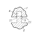
図4〜図6に、環状溝(4)と環状突出部(5)の別の例を示す。図4は環状溝(4)に空気溜まり(20)を設けて鍛圧時の空気の巻き込みが起こらないようにしたものである。図5は環状溝(4)に面取り部(21)を設けて環状溝(4)に環状突出部(5)を組み合わせ易くしたものである。また図6は環状突出部(5)に面取り部(22)を設けて環状溝(4)に環状突出部(5)を組み合わせ易くしたものである。
【0034】
図7〜図9は、環状溝と環状突出部の変形例を示す。
図7(a)(b)は、アルミニウム部材(1)の接合面に断面が台形の環状溝(23)を設け、またアルミニウム部材(2)には対向する断面が台形の環状突出部(24)を設けたものである。この場合も台形の環状溝(23)と台形の環状突出部(24)の大きさは環状溝に環状突出部が充満されるようする。環状溝、環状突出部の機械加工が容易であり、また鍛圧時の空気の巻き込みは起り難いものである。
【0035】
図8は、環状溝(25)の断面が逆台形で、環状突出部(26)が断面コの字状のものである。これは環状溝に環状突出部を嵌合させることにより、高い密閉度が保たれるとともに、機械的にも強い締結がなされるものである。
図9は、断面コの字状環状溝(27)の角取りしたものであり、また環状突出部(28)が山型のものである。これは環状溝(27)に環状突出部(28)を組み合わせ易くしたものである。
【0036】
【実施例2】
本発明の実施例2について、図10、図11を参照して説明する。
図10、図11は半導体製造装置又は薄型ディスプレー製造装置の基板ホルダーの鍛圧する前のアルミニウム部材の一部を示すものである。
図10に示すように、アルミニウム部材(1)、(2)には加熱ヒーター及び熱電対等の内部装着部品(7)を装着する窪みを形成している。
アルミニウム部材(1)の接合面には断面コの字状の環状溝(4)と環状凸部(30)を設けている。またアルミニウム部材(2)の接合面には対向する断面コの字状の環状突出部(5)と環状凸部(31)を設けている。
【0037】
環状溝(4)と環状突出部(5)は、実施例1で説明したと同様にする。
環状凸部(30)(31)の高さは、環状突出部(5)より低いもので圧縮されて接合面で平坦になるものである。
環状溝(4)に環状突出部(5)を組み合わせて挿入する。また環状凸部(30)と環状凸部(31)を合わせて鍛圧する。鍛圧により環状溝(4)に環状突出部(5)は圧縮され充満する。それにより締結部は密閉される。
また鍛圧では、板厚全体を圧縮することより環状凸部(30)と環状凸部(31)は圧着(金属接合)され、外周部も密な接合が得られる。
【0038】
具体的に、部材(1)、(2)として純度99.5%以上の純アルミニウムを用い、環状溝(4)の幅a7.0mm、深さb7.0mm、環状突出部(5)の幅c6.9mm、高さd9.0mm、のものであり、環状凸部(30)と環状凸部(31)は、高さ4mm、幅10mmで、これを鍛圧し環状突出部(5)を圧縮し環状溝(4)に充満され、また、環状凸部(31)は圧着(金属接合)され、接合面で平坦であった。
得られた基板ホルダーは、10−8〜10−10Torrの高真空でもリークが生じることなく、また、外周端部の接合部からの処理液の浸透を防止できた。
【0039】
図11は、アルミニウム部材(1)、(2)には加熱ヒーター及び熱電対等の内部装着部品(7)を装着する窪みを形成し、アルミニウム部材(1)の接合面には断面コの字状の環状溝(4)と環状凸部(32)を設け、またアルミニウム部材(2)の接合面には対向する断面コの字状の環状突出部(5)を設けている。アルミニウム部材(2)には環状凸部を設けていないものである。
環状溝(4)に環状突出部(5)を挿入する。また環状凸部(32)は凸部のない平面に対向させて鍛圧する。鍛圧により環状溝(4)に環状突出部(5)は圧縮され充満する。それにより締結部は密閉される。また鍛圧では、板厚全体を圧縮することより環状凸部(32)は圧着(金属接合)され、外周部も密な接合が得られるものである。
【0040】
【実施例3】
本発明の実施例3について、図12を参照して説明する。
図12は半導体製造装置又は薄型ディスプレー製造装置の基板ホルダーの鍛圧する前のアルミニウム部材の一部を示すものである。
図12に示すように、アルミニウム部材(1)、(2)には加熱ヒーター及び熱電対等の内部装着部品(7)を装着する窪みを形成し、アルミニウム部材(1)の接合面には環状凸部(33)を、またアルミニウム部材(2)の接合面には環状凸部(34)を設けている。
接合面の環状凸部(33)と環状凸部(34)を合わせ、鍛圧により、板厚全体を圧縮する。それにより環状凸部(33)と環状凸部(34)は圧着(金属接合)され、密閉に接合される。
【0041】
【発明の効果】
以上説明したように、本発明によれば、環状溝に環状突出部を鍛圧圧縮して締結させることで高度な密閉度が得られるという効果を有する。即ち、締結部のシールは鍛接され、接合部が物理的に圧着することで、ピンホール等の欠陥を防止でき、高真空度で使用しても高い気密性を保つことができる。また両者が金属接合しているため使用温度を500℃前後の高温でも高度な密閉度が保たれる。また機械加工により溝、突出部を形成し鍛圧することで、締結部が金属接合した圧漏れのない密封体、半導体製造装置又は薄型ディスプレー製造装置の基板ホルダーが得られるので、低コストでの製造が可能となる。さらに、従来技術のように溶湯を使用しないため、基板ホルダー内に入れる部品、部材を高温の溶湯にさらすことがなく装着できる。またボルトナット締結によるスペースを必要とせず、また高精度加工のOリング溝を必要としないので安価に製造できるという効果を奏するものである。
また、一方の部材の環状溝の外側及び/又はもう一方の部材の環状突出部の外側の全周に設けた環状凸部を合わせて、鍛圧圧縮し金属接合させたものであるので、環状溝に環状突出部が圧入して高度な密閉度を確保するとともに外周部のより密な接合を確保することができ、外周端部の接合部から処理液が浸透することを防止することができるという効果を奏するものである。
【図面の簡単な説明】
【図1】本発明実施例の半導体製造装置又は薄型ディスプレー製造装置の基板ホルダーを示す図
【図2】本発明実施例1の基板ホルダーの製造工程を示す図
【図3】本発明実施例1の基板ホルダーの製造工程を示す図
【図4】本発明の実施例1を示す図
【図5】本発明の実施例1を示す図
【図6】本発明の実施例1を示す図
【図7】本発明の実施例1を示す図
【図8】本発明の実施例1を示す図
【図9】本発明の実施例1を示す図
【図10】本発明の実施例2を示す図
【図11】本発明の実施例2を示す図
【図12】本発明の実施例3を示す図
【図13】従来例を示す図
【図14】従来例を示す図
【図15】従来例を示す図
【符号の説明】
1,2 アルミニウム部材
3 締結部
4 環状溝
5 環状突出部
7 加熱ヒーター及び熱電対
8 異種金属若しくは異種材料[0001]
TECHNICAL FIELD OF THE INVENTION
The present invention relates to a sealed body such as a vacuum chamber made of an aluminum or aluminum alloy member, and a substrate holder of a semiconductor manufacturing device or a thin display manufacturing device and a method of manufacturing the same. Internal mounting parts such as a sealed body such as a vacuum chamber, a heater, a thermocouple, and an electrode, and a substrate holder for a semiconductor manufacturing apparatus or a thin display in which a dissimilar metal or a dissimilar material is wrapped with aluminum or an aluminum alloy as appropriate. It relates to the manufacturing method.
[0002]
[Prior art]
A substrate holder of a semiconductor manufacturing apparatus is one in which internally mounted components such as a heater, a thermocouple, an electrode, a dissimilar metal, and a dissimilar material are wrapped in aluminum or an aluminum alloy, as shown in FIGS. Has been.
FIG. 13 shows a substrate holder in which an internally mounted component such as a heater and a thermocouple (7), a dissimilar metal or dissimilar material (8) is covered with aluminum members (11) and (12), and the outer periphery thereof is welded. Further, a terminal (9) for a heater and a thermocouple is provided.
[0003]
FIG. 14 shows a substrate holder in which an internally mounted component such as a heater and a thermocouple (7), a dissimilar metal or dissimilar material (8) is cast and wrapped with an aluminum member (14).
FIG. 15 shows a heater and thermocouple (7), internally mounted components such as dissimilar metals or dissimilar materials (8) covered with aluminum members (11), (12) and an O-ring (15) on the contact surface (17). ) And a substrate holder fastened with bolts (16).
[0004]
[Problems to be solved by the invention]
The conventional substrate holder by welding shown in FIG. 13 has a problem of high cost because it is welded all around, and is used in a chamber under a high vacuum due to pinholes and entrapped gas generated during welding. In this case, there is a problem that the degree of vacuum is reduced due to the leakage from the pinhole or the influence of gas, the reliability of the manufactured semiconductor is reduced, and the yield is deteriorated.
In the case where the internal mounting parts shown in FIG. 14 are cast, the aluminum or aluminum alloy is used in a molten state, so that there is a problem of damage to the mounting parts incorporated therein, and a pin generated when the aluminum member (14) is cast. When used in a chamber under a high vacuum due to the influence of holes and entrained gas, there is a problem that the degree of vacuum is reduced, the reliability of the manufactured semiconductor is reduced, and the yield is reduced.
[0005]
Further, the seal packing using the O-ring and the bolting shown in FIG. 15 have a problem that the seal packing cannot be used in a temperature range exceeding 300 ° C. due to the heat resistance of the seal packing. There is a problem that a space for providing the groove and the bolt hole is required, and the device cannot be made compact. The present invention provides a substrate holder for a semiconductor manufacturing apparatus which has high reliability even when used under high vacuum and high temperature, that is, high airtightness, and can withstand high temperature use, and a method for manufacturing the same.
[0006]
[Means for Solving the Problems]
The present invention has been achieved to achieve the above object, and in a sealed body such as a vacuum chamber made of an aluminum or aluminum alloy member, a sealed body made of an aluminum or aluminum alloy member, wherein the sealed body is made of an aluminum or aluminum alloy member. Consists of An annular protrusion provided on the entire periphery of the joining surface of the other member, and an annular protrusion provided on the entire periphery of the joining surface of the other member. combination , Apply stress more than hot deformation resistance Forging compression Fill the annular groove into the annular groove A pressure-free leak-tight seal made of aluminum or an aluminum alloy member having a metal-joined fastening portion.
The present invention also relates to a sealed body such as a vacuum chamber made of an aluminum or aluminum alloy member, wherein the sealed body is made of an aluminum or aluminum alloy member. Consists of An annular groove provided on the entire periphery of the joining surface of one member is combined with an annular projection provided on the entire periphery of the joining surface of the other member. By combining the annular protrusions provided on the entire outer periphery of the groove and / or the outer periphery of the annular protrusion of the other member, Apply stress more than hot deformation resistance Forging compression It has a fastening part that is filled with an annular protruding part in an annular groove and metal-joined, and the annular convex part on the outer periphery is compressed and metal-joined A sealed body made of aluminum or an aluminum alloy member without pressure leakage.
[0007]
The present invention also relates to a sealed body such as a vacuum chamber made of an aluminum or aluminum alloy member, wherein the sealed body is made of an aluminum or aluminum alloy member. Consists of A plurality of members are joined, one member is provided with an annular convex portion on the entire periphery of the joining surface, and the other member is provided with an annular convex portion on the entire periphery of the joining surface. An annular convex portion provided on the entire periphery of the joining surface of the other member is an annular convex portion provided on the entire periphery of the joining surface of the other member. With a stress greater than the hot deformation resistance A sealed body made of aluminum or an aluminum alloy member, which has a fastening portion forged and compressed and metal-joined, without pressure leakage.
Further, the present invention is characterized in that the plurality of members of aluminum or aluminum alloy constituting the sealing body are made of the same material or different materials.
[0008]
The present invention also provides a substrate holder of a semiconductor manufacturing device or a thin display manufacturing device that wraps an internally mounted component with aluminum or an aluminum alloy member, wherein the aluminum or aluminum alloy member wrapping the internally mounted component is obtained by joining a plurality of members, The annular protrusion provided on the entire circumference of the joining surface of the other member is inserted into the annular groove provided on the entire circumference of the joining surface of one member. combination , Apply stress more than hot deformation resistance Forging compression Fill the annular groove into the annular groove A substrate holder for a semiconductor manufacturing apparatus or a thin display manufacturing apparatus, which is wrapped with aluminum or an aluminum alloy member, having a fastening portion joined by metal bonding.
The present invention also provides a substrate holder of a semiconductor manufacturing device or a thin display manufacturing device that wraps an internally mounted component with aluminum or an aluminum alloy member, wherein the aluminum or aluminum alloy member wrapping the internally mounted component is obtained by joining a plurality of members, The annular groove provided on the entire periphery of the joining surface of the one member is combined with the annular protrusion provided on the entire periphery of the joining surface of the other member, and the outside of the annular groove of the one member and / or By combining the annular projections provided on the entire outer periphery of the annular projection of one member, Apply stress more than hot deformation resistance Forging compression It has a fastening part that is filled with an annular protruding part in an annular groove and metal-joined, and the annular convex part on the outer periphery is compressed and metal-joined A substrate holder of a semiconductor manufacturing apparatus or a thin display manufacturing apparatus which is wrapped with aluminum or an aluminum alloy member.
[0009]
The present invention also provides a substrate holder of a semiconductor manufacturing device or a thin display manufacturing device that wraps an internally mounted component with aluminum or an aluminum alloy member, wherein the aluminum or aluminum alloy member wrapping the internally mounted component is obtained by joining a plurality of members, One member is provided with an annular protrusion on the entire periphery of the joining surface, and the other member is provided with an annular protrusion on the entire periphery of the joint surface, and is provided on the entire periphery of the joining surface of one member. The annular convex portion provided on the entire surface of the joining surface of the other member With a stress greater than the hot deformation resistance A substrate holder for a semiconductor manufacturing device or a thin display manufacturing device, which is surrounded by aluminum or an aluminum alloy member and has a fastening portion which is forged, compressed and metal-joined.
Further, the substrate holder of the semiconductor manufacturing apparatus or the thin display manufacturing apparatus of the present invention is characterized in that a plurality of aluminum or aluminum alloy members enclosing the internally mounted components are made of the same material or different materials.
[0010]
The present invention also relates to a method for manufacturing a substrate holder of a semiconductor manufacturing apparatus or a thin display manufacturing apparatus in which an internally mounted component is wrapped with an aluminum or aluminum alloy member, wherein the aluminum or aluminum alloy member is a bonding surface of one of a plurality of members. An annular groove is provided on the entire periphery of the member, an annular protrusion opposed to the annular groove is provided on the joint surface of the other member on the entire periphery, the annular protrusion is combined with the annular groove, and an annular protrusion is provided on the annular groove. Insert Apply a stress higher than hot deformation resistance at 300 ~ 500 ℃ By forging compression Fill the annular groove into the annular groove This is a method for manufacturing a substrate holder of a semiconductor manufacturing apparatus or a thin display manufacturing apparatus which is wrapped with an aluminum or aluminum alloy member, which is characterized by being metal-joined.
The present invention also relates to a method for manufacturing a substrate holder of a semiconductor manufacturing apparatus or a thin display manufacturing apparatus in which an internally mounted component is wrapped with an aluminum or aluminum alloy member, wherein the aluminum or aluminum alloy member is a bonding surface of one of a plurality of members. Is provided around the entire periphery of the member, an annular protrusion facing the annular groove is provided on the joint surface of the other member on the entire periphery, and the outside of the annular groove of the one member and / or the other member is provided. An annular projection is provided on the entire outer periphery of the annular projection, and the annular projection is inserted into the annular groove by combining the annular projection with the annular groove, and the annular projection is aligned, Apply a stress higher than hot deformation resistance at 300 ~ 500 ℃ By forging compression It has a fastening part that is filled with an annular protruding part in an annular groove and metal-joined, and the annular convex part on the outer periphery is compressed and metal-joined A method for manufacturing a substrate holder of a semiconductor manufacturing apparatus or a thin display manufacturing apparatus, which is wrapped with an aluminum or aluminum alloy member.
[0011]
The present invention also provides a method for manufacturing a substrate holder of a semiconductor manufacturing apparatus, wherein an internally mounted component is wrapped with an aluminum or aluminum alloy member, wherein the aluminum or aluminum alloy member is formed in a ring around the entire joint surface of one of the plurality of members. A convex portion is provided, an annular convex portion is provided on the entire periphery of the joining surface of the other member facing the annular convex portion, and the annular convex portion of one member and the annular convex portion of the other member are combined, Apply a stress higher than hot deformation resistance at 300 ~ 500 ℃ A method for manufacturing a substrate holder for a semiconductor manufacturing apparatus or a thin display manufacturing apparatus which is wrapped with an aluminum or aluminum alloy member, wherein a plurality of members are fastened and metal-joined by forging compression.
Further, the method of manufacturing a substrate holder of a semiconductor manufacturing apparatus or a thin display manufacturing apparatus of the present invention is characterized in that a plurality of members made of aluminum or an aluminum alloy wrapping an internally mounted component are made of the same material or different materials. .
[0012]
[Action]
In the present invention, a plurality of members of aluminum or an aluminum alloy constituting the sealing body apply a partial high load to the annular groove of the joining surface of one member and the annular protrusion of the joining surface of the other member. Inserted, forged and compressed to fill the annular protrusion into the annular groove, fastened, and metal-bonded, so the annular protrusion presses into the annular groove due to the volume difference between the groove and the protrusion, ensuring a high degree of sealing To do.
In addition, the aluminum or aluminum alloy member constituting the sealing body is combined with an annular groove provided on the entire periphery of the joining surface of one member and an annular protrusion provided on the entire periphery of the joining surface of the other member, Since the annular projections provided on the outer periphery of the annular groove of the one member and / or the entire outer periphery of the annular protrusion of the other member are joined together and forged and compressed and metal-joined, the annular groove is formed. The annular protruding part is press-fitted to ensure a high degree of sealing, and the annular convex part on the outer periphery is compressed and metal-joined, so that a tighter joint of the outer periphery can be ensured. It is possible to prevent the treatment liquid from penetrating from the joint at the end.
Further, in the aluminum or aluminum alloy member constituting the sealing body, one member is provided with an annular convex portion all around the joining surface, and the other member is also provided with an annular convex portion around the entire joining surface. The protruding portion is forged and compressed to be metal-joined, so that a higher degree of sealing can be ensured.
[0013]
Further, the present invention provides, as a substrate holder of a semiconductor manufacturing apparatus or a thin display manufacturing apparatus, a plurality of aluminum or aluminum alloy members wrapping an internally mounted component, in an annular groove of a joining surface of one of the members, and of the other member. The annular protruding part of the joining surface is concentrated and applied with a high load, inserted, forged and compressed, filling the annular protruding part into the annular groove, fastening and metal-joining, so the annular part due to the volume difference between the groove part and the protruding part The annular projection is press-fitted into the groove to ensure a high degree of sealing.
[0014]
The present invention also provides a semiconductor manufacturing apparatus or a thin display manufacturing apparatus, in which a plurality of aluminum or aluminum alloy members wrapping internally mounted components are provided in an annular groove provided on the entire circumference of a joining surface of one of the members. The annular projections provided on the entire circumference of the joining surface of one member are combined, and the annular projections provided on the entire circumference outside the annular groove of the one member and / or outside the annular projection of the other member. Since the parts are joined together and forged and compressed to form a metal joint, the annular protrusion is press-fitted into the annular groove to ensure a high degree of sealing, and the annular convex part on the outer periphery is compressed and metal-joined. For this reason, it is possible to secure a tighter joint at the outer peripheral portion, and it is possible to prevent the treatment liquid from permeating from the joined portion at the outer peripheral end.
[0015]
In addition, the present invention provides a plurality of aluminum or aluminum alloy members wrapping internally mounted components as a substrate holder of a semiconductor manufacturing apparatus or a thin display manufacturing apparatus, wherein one member is provided with an annular convex portion on the entire circumference of a bonding surface, and the other is provided. An annular convex portion is provided on the entire joint surface of the member, and the annular convex portion is subjected to forging compression and metal-joined, so that a higher degree of sealing can be ensured.
[0016]
As described above, in the present invention, not only press-fitting of the annular protruding portion but also selective compression of only the joint portion of the aluminum or aluminum alloy member to be joined and metal joining are performed, so that a higher degree of sealing is ensured. Is what you can do. Further, since the fastening portion is metal-joined, a high degree of sealing is maintained even at a high temperature. In particular, it is preferable that the fastening portion is metal-joined in a temperature range of 300 to 500 ° C. At a high operating temperature of about 500 ° C, it is excellent in pressure-bonding property and a high degree of sealing can be maintained.
[0017]
Further, since the substrate holder of the semiconductor manufacturing apparatus or the thin display manufacturing apparatus of the present invention is entirely covered with aluminum or an aluminum alloy member, it has corrosion resistance against corrosive gas. For example, when a silane gas is used in the manufacture of a semiconductor, a holder, a chamber, and the like are contaminated by Si contained in a component of the silane gas. In order to clean it, a fluorine-containing cleaning gas is ventilated. However, since the entire surface is covered with aluminum or an aluminum alloy member, it has corrosion resistance to such a cleaning gas (fluorine-containing gas). .
[0018]
BEST MODE FOR CARRYING OUT THE INVENTION
An embodiment of the present invention will be described in detail.
In the present invention, as a sealed body made of aluminum or an aluminum alloy member without pressure leakage, a vacuum chamber and a sealed container are used. The vacuum chamber is composed of a plurality of aluminum or aluminum alloy members, and has a high degree of sealing without leakage from the joining surfaces of those members. That is, it is excellent in leak resistance and can cope with a high vacuum required in a semiconductor manufacturing apparatus. The hermetically sealed container wraps the internally mounted components and is used as a substrate holder of a semiconductor manufacturing apparatus or a thin display manufacturing apparatus.
In addition to the substrate holder of the flat panel display manufacturing apparatus, the sealing body is used for a semiconductor device or the like, and a vacuum processing apparatus for the semiconductor device or the like includes a processing chamber, a transfer chamber, an inlet / outlet chamber, and the like. In order to transfer the material between the chambers, each chamber is provided with a window for taking in and out the material as needed, and further has an upper lid that can be opened for maintenance or the like. The above-described processing chamber, transfer chamber, inlet / outlet chamber, etc. are all chambers of a semiconductor manufacturing apparatus. In this case, the bottom plate and the side plate of each chamber are forged and pressed by the method of the present invention. Use what you have.
Further, a highly airtight industrial waste treatment container or the like is also manufactured and used by the same method as the substrate holder of the semiconductor manufacturing apparatus or the flat panel display manufacturing apparatus described above. That is, at least the bottom plate and the side plate of the container are metal-joined by forging pressure welding according to the method of the present invention, and a method such as forging pressure welding, welding, or mechanical sealing can be selected for the upper lid as necessary.
[0019]
In the present invention, for example, a heater, a thermocouple, an electrode, a dissimilar metal, and a dissimilar material can be used as the internal components of the substrate holder of the semiconductor manufacturing apparatus or the thin display manufacturing apparatus. Appropriate internal components are mounted according to the semiconductor manufacturing process. A heater, a thermocouple, an electrode, and the like serve to provide a function to the substrate holder. Further, if necessary, different types of metals and different materials are used to impart characteristics to the substrate holder. For example, an aluminum matrix composite material in which ceramic fibers, ceramic whiskers, carbon fibers, or the like are dispersed can reduce the coefficient of thermal expansion of the substrate holder, increase strength and rigidity at high temperatures, and make it less likely to be thermally deformed.
[0020]
Specific examples of the substrate holder of the thin panel display manufacturing apparatus of the present invention include a liquid crystal display (LCD), a plasma display (PDP), a field emission display (FED), and an organic EL (electroluminescence) display. EL), a substrate holder of a device for manufacturing a light emitting diode (LED).
[0021]
Although the material and manufacturing method of aluminum or aluminum alloy surrounding the internally mounted component are not specified, it is preferable to use a rolled plate or a forged product having few internal defects in consideration of leak resistance.
Further, from the viewpoint of corrosion resistance to the cleaning gas, JIS1050 having a purity of 99.5% or more is most desirable for the aluminum material, but JIS1100 (Si and Fe: 1.0%, Cu: 0.05 to 0.20%, Mn: 0.05% or less, Zn: 0.10% or less, balance Al), JIS3003 (Si: 0.6% or less, Fe: 0.7% or less, Cu: 0.05 to 0.20%, Mn: 1) 0.0 to 1.5%, Zn: 0.10% or less, balance Al), JIS6063 (Si: 0.20 to 0.6%, Fe: 0.35% or less, Cu: 0.10% or less, Mn : 1.0% or less, Mg: 0.45 to 0.9%, Cr: 0.10% or less, Zn: 0.10% or less, Ti: 0.10% or less, balance Al), JIS6061 (Si: 0.40 to 0.8%, Fe: 0.7% or less, Cu: 0.15 to 0.40% Mn: 0.15% or less, Mg: 0.8 to 1.2%, Cr: 0.04 to 0.35%, Zn: 0.25% or less, Ti: 0.15% or less, balance Al) JIS3004 (Si: 0.03% or less, Fe: 0.7% or less, Cu: 0.25% or less, Mn: 1.0 to 1.5%, Mg: 0.8 to 1.3%, Zn: 0.10% or less, with the balance being Al). In addition, a low Mg content Al-Mg alloy or the like can be used as long as the pressure contact property is satisfied and metal bonding can be secured.
[0022]
In the present invention, the aluminum or aluminum alloy member joins a plurality of members, for example, two members, and wraps the internally mounted component.
The aluminum or aluminum alloy member is provided with an annular groove on the joining surface of one member. This annular groove is provided on the entire periphery at the outer periphery surrounding the internally mounted component. An annular protrusion is provided on the joining surface of the other member so as to face the annular groove.
One or more sets of annular grooves and protrusions are provided. Further, the annular groove and the protruding portion provided on the entire outer periphery may be provided on the joining surface of the member in a rectangular or polygonal annular shape, or may be provided in a circular annular shape.
The annular groove and the annular protrusion are formed by, for example, machining.
It is desirable to clean the surface of the annular groove and the annular protrusion as a pretreatment for forging. For example, (1) removing oil on the surface with nitric acid, (2) washing with water, (3) chemical treatment (etching with an alkaline solution), (4) washing with water, (5) washing with nitric acid, (6) washing with water, (7) ▼ Rinse and clean the surface with appropriate steps such as hot water washing.
[0023]
The two members are formed by combining an annular groove with an annular protrusion, forging after insertion, filling the annular groove with the annular protrusion, and further forging the metal to join them together. This degree of sealing, that is, leak resistance, can cope with a high vacuum required in a semiconductor manufacturing apparatus. -8 -10 -10 It can respond to the high vacuum of Torr.
When the annular projection is inserted into the annular groove, the width of the projection may be slightly larger than the width of the annular groove as long as insertion is possible, so that a so-called press-fit state may be obtained.
For the joining of the fitting portions, pure aluminum having a purity of 99.5% or more is most easily press-fitted, but JIS1100 with a purity of 99.0% or more, JIS3003 or JIS3004 of Al-Mn series, or JIS6063. It can be pressed even in the case of an alloy such as JIS6061 or JIS6061.
Also, after inserting the annular projecting portion into the annular groove, forging compression is performed, the fastening portion is sealed and filled and fastened, and furthermore, if the plurality of members of aluminum or aluminum alloy to be metal-joined are the same material, the plurality of members are deformed by forging compression. Comrades are press-fitted and are easily physically bonded to metal.
Further, even if a plurality of aluminum or aluminum alloy members to be metal-joined are made of different materials, the plurality of members are pressure-bonded and physically bonded to each other by deformation at the time of forging compression. For example, JIS1000-based materials of different types are used. The aluminum material and the JIS 3000 type aluminum material are pressed against each other by deformation at the time of forging compression, and are physically metal-joined.
Such metal joining of a plurality of members of the same or different types is performed in a temperature range of 300 to 500 ° C., and a forging pressure welding temperature of 350 to 500 ° C. is preferable.
In the above forging pressure welding temperature range, when welding is performed by applying a stress equal to or greater than the hot deformation resistance of the member to the joining surface, a minute deformation occurs in the fastening portion, the joining surface is metal-joined, and high airtightness is obtained. Can be The stress applied to the fastening portion is desirably high, and is particularly preferably 2-3 times or more the hot deformation resistance. If the forging pressure welding temperature is lower than 300 ° C., a metal bonding state cannot be obtained, and if it exceeds 500 ° C., deformation during forging pressure welding is too much, and it is difficult to obtain predetermined dimensions and shapes as a product of the joining member. Problems arise. Therefore, a range of 300 to 500 ° C. is used as the forging pressure contact temperature.
As a specific example in Table 1, in order to evaluate the joining strength, an annular convex portion is provided on one surface of the aluminum member, another convex portion is provided on the joint surface of the other member, and these members are combined to form a forging pressure. In order to determine the bonding strength when metal bonding is performed by pressure welding, a rod-shaped forging pressure welding member (square having a bonding surface of 15 mm × 15 mm) is prepared, and the joining member, forging temperature, The relationship of the bonding strength was determined.
Forging pressure welding is performed by a method of applying a predetermined deformation so that the joining surface of the rod-shaped member comes into contact with the joining surface of another rod-shaped member, and the joining surface of one member and the joining surface of the other member are brought into pressure contact with each other. Was. The bonding strength is an apparent value obtained by dividing the breaking load of the member when the member pressed by forging pressure is pulled outward in the normal direction (perpendicular to the pressing surface) by the cross-sectional area of the bonding surface.
In addition, a joining member shows aluminum and aluminum alloy shown by JIS mentioned later. Specifically, 1050 + 1050 indicates that forging pressure welding was performed using a JIS1050 alloy member and a JIS1050 alloy member, and 1050 + 3003 indicates that forging pressure welding was performed using a JIS1050 alloy member and JIS3003 alloy member.
[Table 1]
As an example, the test piece No. 7, the behavior of the additional element at the interface between the joints 3003 and 1050 was investigated using Mn added to 3003 but not added to 1050. As a result, it was confirmed that Mn of 3003 was diffused to the 1050 side although it was about 10 μm or less.
Further, in the diffusion of Fe and Si of the same material such as 1050, since the diffusion coefficients of Fe and Si are about one order larger than that of Mn, the movement distance of these elements at the bonding interface is at least 2% in the case of Mn. It is considered to be on the order of three times (several tens of μm). Therefore, it is considered that the diffusion of the impurity elements such as Mn, Fe, and Si strengthens the metal junction between the two.
[0024]
As the annular groove formed on the joining surface of the aluminum or aluminum alloy member, a U-shaped (long), trapezoidal, inverted trapezoidal or the like is used in cross section. Considering this, a U-shaped (long) cross section and a trapezoid are preferable. As the annular protrusion combined with the annular groove, a U-shaped cross section (a long shape), a trapezoid, or the like is used. Further, in order to facilitate the combination of the projecting portion with the annular groove, the tip of the projecting portion having a U-shaped cross section may be chamfered.
For example, when the annular groove has a U-shaped cross-section and the annular protrusion combined therewith also has a U-shaped cross-section, the width of the U-shaped annular groove is a, the depth is b, and the depth of the cross-section is U. Assuming that the width of the U-shaped annular protrusion is c and the height is d, a × b ≦ c × d, b / d ≦ 1.0, forging compression is performed, and the annular groove is filled with the annular protrusion. Preferred for sealing. In particular, when the cross-sectional area of the protrusion is larger than the cross-sectional area of the groove, when a material corresponding to the surplus cross-sectional area of the protrusion is pushed into the groove, a higher pressure is obtained to enlarge the cross-sectional area of the groove, and the adhesion is increased.
In order to combine the annular projection with the U-shaped annular groove, the width of the annular groove can be inserted even if it is extremely slightly larger than the width of the U-shaped annular projection. In view of this, it is preferable that the annular groove is small, and in order to insert the annular protrusion into the annular groove for hermetic sealing, the depth of the annular groove is preferably larger than the height of the U-shaped annular protrusion.
[0025]
The annular projection formed on the joining surface of the aluminum or aluminum alloy member is provided on the entire outer periphery of the annular groove of one member and / or the outer periphery of the annular protrusion of the other member. The annular projection has a height lower than that of the annular projection, and is compressed to be flat on the joining surface and metal-joined.
Also, on the joining surface of the aluminum or aluminum alloy member, only the annular convex portion is provided on the entire periphery of the joining surface without providing the annular groove and the annular projecting portion, and the forging is performed so that the annular convex portion becomes flat on the joining surface. The members are deformed due to the compression, and are pressed and physically joined to the metal.
[0026]
Embodiment 1
First Embodiment A first embodiment of the present invention will be described with reference to FIGS.
FIG. 1 is a view showing a substrate holder of a semiconductor manufacturing apparatus or a thin display manufacturing apparatus arranged in a chamber according to Embodiment 1 of the present invention. FIG. 1 (a) is a sectional view and FIG. 1 (b) is a plan view. A heater and a thermocouple (7), a substrate holder in which internally mounted components such as dissimilar metals or dissimilar materials (8) are joined and wrapped with aluminum members (1) and (2). A terminal (9) is provided and located in the chamber (10). On the joint surface of the aluminum members (1) and (2), an annular groove and an annular protrusion are formed on the entire periphery in a square shape. After insertion, the annular groove and the annular protrusion are filled with forging and compression, and further compressed to reduce the metal flow. The formed fastening part (3) is sealed and physically joined to the metal. Placed in the chamber.
[0027]
FIGS. 2A, 2B, 3A, 3B, and 3C are diagrams showing a manufacturing process of the substrate holder according to the first embodiment of the present invention.
As shown in FIG. 2 (a), the aluminum members (1) and (2) are formed with depressions for mounting internal mounting parts (7) such as a heater and a thermocouple.
An annular groove (4) having a U-shaped cross section is provided on the joining surface of the aluminum member (1), and an annular projecting portion (5) having a U-shaped cross section facing the joining surface of the aluminum member (2). Provide. FIG. 2B is an enlarged view of the annular groove (4) and the annular protrusion (5). The width of the annular groove (4) is a, the depth is b, and the annular protrusion (5). The width was c and the height was d.
[0028]
Next, as shown in FIG. 3 (a), the internal mounting parts (7) were mounted on the aluminum members (1) and (2), and the annular protrusion (5) was combined with the annular groove (4).
FIG. 3B is an enlarged view of a combination of the annular groove (4) and the annular protrusion (5). The annular protrusion (5) having the width c is inserted into the annular groove (4) having the width a. The height d of the annular projection (5) is longer than the depth b of the annular groove (4).
Thus, the annular groove (4) was combined with the annular protrusion (5), and forging was performed as indicated by the arrow in FIG. Due to the forging pressure, as shown in FIG. 3 (c), a ′ = c ′ and b ′ = d ′ after deformation, and the annular protrusion (5) is compressed and filled in the annular groove (4). Thereby, the fastening portion is sealed.
In the case of forging, by compressing the entire thickness of the plate, a tightly closed state in which the fastening portion is physically pressed (metal-bonded) can be obtained more effectively.
[0029]
An example of the relationship between the annular groove (4) and the annular protrusion (5) will be described with reference to the diagram shown in FIG.
When the width of the annular groove (4) is a, the depth is b, and the width of the annular protrusion (5) is c and the height is d, the following relationship is preferable.
a × b ≦ c × d
b / d ≦ 1.0
d / c ≦ 6 (more preferably, d / c ≦ 4)
[0030]
The relationship of a × b ≦ c × d and b / d ≦ 1.0 is that the annular projection (5) is press-fitted into the annular groove (4) by forging compression to seal the fastening portion.
Since the circumference of the annular groove (4) and the annular protrusion (5) are the same, the area of a × b of the annular groove (4) may be larger than the area of c × d of the annular protrusion (5). The volume of the annular protrusion (5) is smaller than the internal volume of the annular groove (4). As a result, the annular groove (4) is not filled with the annular protrusion (5). In order to make the seal sufficient, it is preferable to satisfy the relationship a × b ≦ c × d.
If the width c of the annular projection (5) is too small compared to the width a of the annular groove (4), the annular groove (4) can seal the annular projection (5) when forged. And the sealing may be insufficient.
[0031]
Specifically, pure aluminum having a purity of 99.5% or more is used as the members (1) and (2). The width a of the annular groove (4) is 7.0 mm, the depth b is 7.0 mm, and the width of the annular protrusion (5). For example, a sample having a c of 6.9 mm and a height of 9.0 mm was forged to compress the annular protrusion (5) and fill the annular groove (4). The obtained substrate holder is 10 -8 -10 -10 No leak occurred even at a high vacuum of Torr.
[0032]
If the width c of the annular protrusion (5) is too small compared to the width a of the annular groove (4), the annular protrusion (5) will buckle when forged, and the annular groove (4) will have an annular shape. The protrusion (5) cannot be press-fitted, resulting in insufficient sealing.
[0033]
4 to 6 show another example of the annular groove (4) and the annular protrusion (5). FIG. 4 shows an arrangement in which an air pool (20) is provided in the annular groove (4) to prevent air from being trapped during forging. FIG. 5 shows that the annular groove (4) is provided with a chamfered portion (21) so that the annular groove (4) can be easily combined with the annular projecting portion (5). FIG. 6 shows that the annular projection (5) is provided with a chamfered portion (22) so that the annular groove (4) can be easily combined with the annular projection (5).
[0034]
7 to 9 show modified examples of the annular groove and the annular projection.
FIGS. 7 (a) and 7 (b) show an annular groove (23) having a trapezoidal cross section on the joint surface of the aluminum member (1), and an annular protrusion (24) having a trapezoidal cross section facing the aluminum member (2). ). Also in this case, the size of the trapezoidal annular groove (23) and the trapezoidal annular protrusion (24) is such that the annular groove is filled with the annular protrusion. The machining of the annular groove and the annular projection is easy, and air is hardly entrained at the time of forging.
[0035]
In FIG. 8, the cross section of the annular groove (25) is an inverted trapezoid, and the annular projection (26) has a U-shaped cross section. By fitting the annular protrusion into the annular groove, a high degree of sealing is maintained and mechanically strong fastening is performed.
FIG. 9 is a view in which the annular groove (27) having a U-shaped cross section is chamfered, and the annular protrusion (28) is mountain-shaped. This facilitates the combination of the annular groove (27) with the annular protrusion (28).
[0036]
Second Embodiment A second embodiment of the present invention will be described with reference to FIGS.
FIGS. 10 and 11 show a part of an aluminum member before forging of a substrate holder of a semiconductor manufacturing apparatus or a thin display manufacturing apparatus.
As shown in FIG. 10, the aluminum members (1) and (2) are formed with depressions for mounting internal mounting parts (7) such as a heater and a thermocouple.
An annular groove (4) having a U-shaped cross section and an annular projection (30) are provided on the joint surface of the aluminum member (1). Further, an annular protrusion (5) and an annular protrusion (31) having a U-shaped cross section are provided on the joint surface of the aluminum member (2).
[0037]
The annular groove (4) and the annular protrusion (5) are the same as described in the first embodiment.
The height of the annular projections (30) and (31) is lower than that of the annular projection (5), and is compressed to be flat at the joint surface.
The annular groove (4) is inserted in combination with the annular protrusion (5). In addition, the annular convex portion (30) and the annular convex portion (31) are forged together. The annular protrusion (5) is compressed and filled in the annular groove (4) by the forging pressure. Thereby, the fastening portion is sealed.
In the forging pressure, by compressing the entire plate thickness, the annular convex portion (30) and the annular convex portion (31) are pressure-bonded (metal-bonded), and the outer peripheral portion is also tightly bonded.
[0038]
Specifically, pure aluminum having a purity of 99.5% or more is used for the members (1) and (2), the width a of the annular groove (4) is 7.0 mm, the depth b is 7.0 mm, and the width of the annular protrusion (5). c is 6.9 mm and height is 9.0 mm. The annular projection (30) and the annular projection (31) have a height of 4 mm and a width of 10 mm, and are forged to compress the annular projection (5). The annular groove (4) was filled, and the annular convex portion (31) was press-bonded (metal-joined) and flat at the joint surface.
The obtained substrate holder is 10 -8 -10 -10 Leakage did not occur even at a high vacuum of Torr, and permeation of the processing liquid from the joint at the outer peripheral end could be prevented.
[0039]
FIG. 11 shows that the aluminum members (1) and (2) are formed with depressions for mounting internal mounting parts (7) such as a heater and a thermocouple, and the joining surface of the aluminum member (1) has a U-shaped cross section. Are provided with an annular groove (4) and an annular convex portion (32), and an annular projecting portion (5) having a U-shaped cross section facing the joint surface of the aluminum member (2). The aluminum member (2) does not have an annular convex portion.
The annular protrusion (5) is inserted into the annular groove (4). Further, the annular convex portion (32) is subjected to forging while facing a flat surface having no convex portion. The annular protrusion (5) is compressed and filled in the annular groove (4) by the forging pressure. Thereby, the fastening portion is sealed. In the forging pressure, by compressing the entire plate thickness, the annular convex portion (32) is press-bonded (metal-bonded) and the outer peripheral portion can be tightly bonded.
[0040]
Third Embodiment A third embodiment of the present invention will be described with reference to FIG.
FIG. 12 shows a part of an aluminum member before forging of a substrate holder of a semiconductor manufacturing apparatus or a thin display manufacturing apparatus.
As shown in FIG. 12, the aluminum members (1) and (2) are formed with depressions for mounting internal mounting parts (7) such as a heater and a thermocouple, and an annular projection is formed on the joining surface of the aluminum member (1). A portion (33) and an annular convex portion (34) are provided on the joining surface of the aluminum member (2).
The annular convex portion (33) and the annular convex portion (34) of the joining surface are combined, and the entire thickness is compressed by forging pressure. As a result, the annular convex portion (33) and the annular convex portion (34) are pressure-bonded (metal-joined) and are hermetically joined.
[0041]
【The invention's effect】
As described above, according to the present invention, there is an effect that a high degree of sealing can be obtained by forging and compressing the annular projection into the annular groove and fastening the annular projection. That is, the seal of the fastening portion is forged and the bonding portion is physically pressed, whereby defects such as pinholes can be prevented, and high airtightness can be maintained even when used at a high degree of vacuum. Also, since both are metal-bonded, a high degree of sealing is maintained even at a use temperature of about 500 ° C. In addition, by forming grooves and protrusions by machining and forging, it is possible to obtain a sealed body in which the fastening part is metal-joined without pressure leakage, and a substrate holder for a semiconductor manufacturing apparatus or a thin display manufacturing apparatus. Becomes possible. Further, since no molten metal is used unlike the prior art, components and members to be put in the substrate holder can be mounted without being exposed to high-temperature molten metal. Further, since there is no need for a space for bolt and nut fastening and no need for an O-ring groove for high-precision processing, it is possible to produce an effect that it can be manufactured at low cost.
Further, the annular protrusions provided on the outer periphery of the annular groove of one member and / or the entire outer periphery of the annular protrusion of the other member are combined, forged and compressed, and metal-joined. The annular projections are press-fitted to ensure a high degree of sealing while ensuring a tighter joint at the outer periphery, preventing the treatment liquid from permeating from the joint at the outer peripheral end. It is effective.
[Brief description of the drawings]
FIG. 1 is a view showing a substrate holder of a semiconductor manufacturing apparatus or a thin display manufacturing apparatus according to an embodiment of the present invention.
FIG. 2 is a diagram showing a manufacturing process of the substrate holder according to the first embodiment of the present invention.
FIG. 3 is a view showing a manufacturing process of the substrate holder according to the first embodiment of the present invention.
FIG. 4 is a diagram showing a first embodiment of the present invention.
FIG. 5 is a diagram showing a first embodiment of the present invention.
FIG. 6 is a diagram showing a first embodiment of the present invention.
FIG. 7 is a diagram showing a first embodiment of the present invention.
FIG. 8 is a diagram showing a first embodiment of the present invention.
FIG. 9 is a diagram showing a first embodiment of the present invention.
FIG. 10 is a diagram showing a second embodiment of the present invention.
FIG. 11 is a diagram showing a second embodiment of the present invention.
FIG. 12 is a diagram showing a third embodiment of the present invention.
FIG. 13 shows a conventional example.
FIG. 14 shows a conventional example.
FIG. 15 shows a conventional example.
[Explanation of symbols]
1,2 aluminum member
3 Fastening part
4 annular groove
5 Annular protrusion
7 Heater and thermocouple
8 Dissimilar metals or dissimilar materials
Claims (12)
Priority Applications (1)
| Application Number | Priority Date | Filing Date | Title |
|---|---|---|---|
| JP268999A JP3552154B2 (en) | 1998-01-12 | 1999-01-08 | Sealed body made of aluminum or aluminum alloy member, substrate holder of semiconductor manufacturing apparatus or thin display manufacturing apparatus, and method of manufacturing the same |
Applications Claiming Priority (3)
| Application Number | Priority Date | Filing Date | Title |
|---|---|---|---|
| JP10-16336 | 1998-01-12 | ||
| JP1633698 | 1998-01-12 | ||
| JP268999A JP3552154B2 (en) | 1998-01-12 | 1999-01-08 | Sealed body made of aluminum or aluminum alloy member, substrate holder of semiconductor manufacturing apparatus or thin display manufacturing apparatus, and method of manufacturing the same |
Publications (2)
| Publication Number | Publication Date |
|---|---|
| JPH11285775A JPH11285775A (en) | 1999-10-19 |
| JP3552154B2 true JP3552154B2 (en) | 2004-08-11 |
Family
ID=26336134
Family Applications (1)
| Application Number | Title | Priority Date | Filing Date |
|---|---|---|---|
| JP268999A Expired - Lifetime JP3552154B2 (en) | 1998-01-12 | 1999-01-08 | Sealed body made of aluminum or aluminum alloy member, substrate holder of semiconductor manufacturing apparatus or thin display manufacturing apparatus, and method of manufacturing the same |
Country Status (1)
| Country | Link |
|---|---|
| JP (1) | JP3552154B2 (en) |
Cited By (1)
| Publication number | Priority date | Publication date | Assignee | Title |
|---|---|---|---|---|
| US8263908B2 (en) | 2004-10-08 | 2012-09-11 | Furukawa-Sky Aluminum Corp. | Heater plate and a method for manufacturing the heater plate |
Families Citing this family (16)
| Publication number | Priority date | Publication date | Assignee | Title |
|---|---|---|---|---|
| JP3578398B2 (en) * | 2000-06-22 | 2004-10-20 | 古河スカイ株式会社 | Gas dispersion plate for film formation and method of manufacturing the same |
| JP4750257B2 (en) * | 2000-10-24 | 2011-08-17 | 古河スカイ株式会社 | Manufacturing method of heat plate in which metal members are joined |
| JP4750258B2 (en) * | 2000-10-24 | 2011-08-17 | 古河スカイ株式会社 | Method for manufacturing fluid circuit member |
| JP4805466B2 (en) * | 2001-03-14 | 2011-11-02 | 古河スカイ株式会社 | Method for manufacturing a heater plate provided with a sheath heater |
| JP2002324655A (en) * | 2001-04-25 | 2002-11-08 | Furukawa Electric Co Ltd:The | Method of manufacturing a heater plate provided with a sheath heater |
| KR101209971B1 (en) * | 2007-12-27 | 2012-12-07 | 카와사키 주코교 카부시키 카이샤 | Dissimilar metal joint structure, tank skirt having the dissimilar metal joint structure, transport ship having the tank skirt, and dissimilar metal member jointing method |
| KR100975637B1 (en) * | 2010-03-10 | 2010-08-17 | 주식회사 포톤 | High efficiency susceptor and the process of manufacture that use cnt |
| KR101147998B1 (en) | 2011-11-14 | 2012-05-24 | 주식회사 포톤 | High efficiency susceptor and method for manufacturing the same |
| TW201318760A (en) * | 2011-11-14 | 2013-05-16 | Ichia Tech Inc | Method for combining compound metal and method for partly combining compound metal |
| CN103137361B (en) * | 2011-11-29 | 2015-07-22 | 毅嘉科技股份有限公司 | Forming method of metal key |
| JP6383385B2 (en) * | 2016-06-30 | 2018-08-29 | 日東精工株式会社 | Method for joining metal members and method for producing metal composite members |
| JP6430442B2 (en) * | 2016-06-28 | 2018-11-28 | 日東精工株式会社 | Non-through bonding method for metal parts |
| WO2018003175A1 (en) * | 2016-06-28 | 2018-01-04 | 日東精工株式会社 | Method for non-penetration joining of members, and non-penetration joining structure |
| CN111955803A (en) * | 2020-08-07 | 2020-11-20 | 深圳麦克韦尔科技有限公司 | Heating element and electronic atomization device adopting same |
| JP7649165B2 (en) * | 2021-02-26 | 2025-03-19 | 日東精工株式会社 | Insulating composite part and method for manufacturing insulating composite part |
| CN115635262A (en) * | 2022-11-29 | 2023-01-24 | 合肥升滕半导体技术有限公司 | Photovoltaic heating plate and processing method thereof |
Family Cites Families (6)
| Publication number | Priority date | Publication date | Assignee | Title |
|---|---|---|---|---|
| JPS55153630A (en) * | 1979-05-21 | 1980-11-29 | Toshiba Corp | Manufacture of cooling path |
| JPS59459U (en) * | 1982-06-22 | 1984-01-05 | セイコーエプソン株式会社 | Substrate holder structure |
| JPS60180629A (en) * | 1984-02-29 | 1985-09-14 | Hitachi Ltd | Joining method of two members |
| JPH0670365B2 (en) * | 1985-09-05 | 1994-09-07 | ヤマハ発動機株式会社 | Valve lifter for internal combustion engine |
| EP0448339B1 (en) * | 1990-03-22 | 1994-03-02 | United Technologies Corporation | Method of forming a hollow blade |
| JPH0919728A (en) * | 1995-07-05 | 1997-01-21 | Atsushi Terada | Mutual extrusion material joining method and liquid cooling heat sink |
-
1999
- 1999-01-08 JP JP268999A patent/JP3552154B2/en not_active Expired - Lifetime
Cited By (1)
| Publication number | Priority date | Publication date | Assignee | Title |
|---|---|---|---|---|
| US8263908B2 (en) | 2004-10-08 | 2012-09-11 | Furukawa-Sky Aluminum Corp. | Heater plate and a method for manufacturing the heater plate |
Also Published As
| Publication number | Publication date |
|---|---|
| JPH11285775A (en) | 1999-10-19 |
Similar Documents
| Publication | Publication Date | Title |
|---|---|---|
| JP3552154B2 (en) | Sealed body made of aluminum or aluminum alloy member, substrate holder of semiconductor manufacturing apparatus or thin display manufacturing apparatus, and method of manufacturing the same | |
| US6376815B1 (en) | Highly gas tight substrate holder and method of manufacturing the same | |
| US7150418B2 (en) | Nozzle plate member for supplying fluids in dispersed manner and manufacturing method of the same | |
| US7143568B2 (en) | Hermetically sealing a container with crushable material and reactive multilayer material | |
| US8263908B2 (en) | Heater plate and a method for manufacturing the heater plate | |
| JP4838992B2 (en) | Heater plate and heater plate manufacturing method | |
| JP3836602B2 (en) | Manufacturing method of vacuum chamber | |
| JP4806179B2 (en) | Heater plate manufacturing method | |
| JP3345852B2 (en) | Base holder for semiconductor manufacturing apparatus and method of manufacturing the same | |
| US7154070B2 (en) | Heater plate and a method for manufacturing the heater plate | |
| JP4805466B2 (en) | Method for manufacturing a heater plate provided with a sheath heater | |
| TWI429314B (en) | Heating plate and heating plate manufacturing method | |
| RU2109606C1 (en) | Method of making soldered telescopic structures | |
| JP4750257B2 (en) | Manufacturing method of heat plate in which metal members are joined | |
| CA2246827C (en) | Sodium secondary battery | |
| JP2013102032A (en) | Glass sealing type thermistor and method for manufacturing the same | |
| JPH01297022A (en) | Metallic vacuum double structure body and manufacture | |
| JPH01268521A (en) | Metallic vacuum double structure and manufacture thereof | |
| CN1799133A (en) | Hermetically sealed product and related methods of manufacture | |
| FR2490627A1 (en) | Assembling ceramic and steel parts, e.g. of pump - using steel sintering shrinkage to form gas- and liq.-tight seal | |
| JPH0520981A (en) | Vacuum valve | |
| JPS6273555A (en) | Sealing of electrolyte cell | |
| JP2001183023A (en) | Manufacturing method for refrigerator | |
| JPH0736456B2 (en) | Gas discharge tube | |
| HK1089513B (en) | Heating plate and manufacturing method thereof |
Legal Events
| Date | Code | Title | Description |
|---|---|---|---|
| A711 | Notification of change in applicant |
Free format text: JAPANESE INTERMEDIATE CODE: A712 Effective date: 20040202 |
|
| TRDD | Decision of grant or rejection written | ||
| A01 | Written decision to grant a patent or to grant a registration (utility model) |
Free format text: JAPANESE INTERMEDIATE CODE: A01 Effective date: 20040406 |
|
| RD02 | Notification of acceptance of power of attorney |
Free format text: JAPANESE INTERMEDIATE CODE: A7422 Effective date: 20040422 |
|
| A61 | First payment of annual fees (during grant procedure) |
Free format text: JAPANESE INTERMEDIATE CODE: A61 Effective date: 20040422 |
|
| R150 | Certificate of patent or registration of utility model |
Free format text: JAPANESE INTERMEDIATE CODE: R150 |
|
| S531 | Written request for registration of change of domicile |
Free format text: JAPANESE INTERMEDIATE CODE: R313531 |
|
| R350 | Written notification of registration of transfer |
Free format text: JAPANESE INTERMEDIATE CODE: R350 |
|
| R250 | Receipt of annual fees |
Free format text: JAPANESE INTERMEDIATE CODE: R250 |
|
| FPAY | Renewal fee payment (event date is renewal date of database) |
Free format text: PAYMENT UNTIL: 20090514 Year of fee payment: 5 |
|
| FPAY | Renewal fee payment (event date is renewal date of database) |
Free format text: PAYMENT UNTIL: 20090514 Year of fee payment: 5 |
|
| FPAY | Renewal fee payment (event date is renewal date of database) |
Free format text: PAYMENT UNTIL: 20100514 Year of fee payment: 6 |
|
| FPAY | Renewal fee payment (event date is renewal date of database) |
Free format text: PAYMENT UNTIL: 20130514 Year of fee payment: 9 |
|
| FPAY | Renewal fee payment (event date is renewal date of database) |
Free format text: PAYMENT UNTIL: 20160514 Year of fee payment: 12 |
|
| S531 | Written request for registration of change of domicile |
Free format text: JAPANESE INTERMEDIATE CODE: R313531 |
|
| S533 | Written request for registration of change of name |
Free format text: JAPANESE INTERMEDIATE CODE: R313533 |
|
| R350 | Written notification of registration of transfer |
Free format text: JAPANESE INTERMEDIATE CODE: R350 |
|
| S111 | Request for change of ownership or part of ownership |
Free format text: JAPANESE INTERMEDIATE CODE: R313111 |
|
| R360 | Written notification for declining of transfer of rights |
Free format text: JAPANESE INTERMEDIATE CODE: R360 |
|
| R360 | Written notification for declining of transfer of rights |
Free format text: JAPANESE INTERMEDIATE CODE: R360 |
|
| R371 | Transfer withdrawn |
Free format text: JAPANESE INTERMEDIATE CODE: R371 |
|
| S111 | Request for change of ownership or part of ownership |
Free format text: JAPANESE INTERMEDIATE CODE: R313111 |
|
| S631 | Written request for registration of reclamation of domicile |
Free format text: JAPANESE INTERMEDIATE CODE: R313631 |
|
| S633 | Written request for registration of reclamation of name |
Free format text: JAPANESE INTERMEDIATE CODE: R313633 |
|
| R350 | Written notification of registration of transfer |
Free format text: JAPANESE INTERMEDIATE CODE: R350 |
|
| R250 | Receipt of annual fees |
Free format text: JAPANESE INTERMEDIATE CODE: R250 |
|
| EXPY | Cancellation because of completion of term |