JP3550468B2 - Mold product paper making equipment - Google Patents
Mold product paper making equipment Download PDFInfo
- Publication number
- JP3550468B2 JP3550468B2 JP24272696A JP24272696A JP3550468B2 JP 3550468 B2 JP3550468 B2 JP 3550468B2 JP 24272696 A JP24272696 A JP 24272696A JP 24272696 A JP24272696 A JP 24272696A JP 3550468 B2 JP3550468 B2 JP 3550468B2
- Authority
- JP
- Japan
- Prior art keywords
- mold
- hollow
- raw material
- male mold
- horizontal
- Prior art date
- Legal status (The legal status is an assumption and is not a legal conclusion. Google has not performed a legal analysis and makes no representation as to the accuracy of the status listed.)
- Expired - Fee Related
Links
Images


Description
【0001】
【発明の属する技術分野】
本発明はパルプモールドによる深さの大きい大形モールド製品を抄造する装置に関するものである。
【0002】
【従来の技術】
従来、大形モールド製品抄造装置(特公平8−19640号)が開発され、深さ100〜150mm程度、肉厚5〜6mmの便器包装用クッション材等のように大形のモールド製品の抄造を行うことができた。
【0003】
ところが中空雄型の垂直昇降距離は水平レール上の摺動枠に設けた中空雄型と、その下方の一定水準位置に停止した中空雌型との高さ距離に限定され、自らその高さ即ちモールド製品の深さは制限される。
【0004】
モールド製品の上記深さを増加するためには水平レールの高さ及び中空雄型を支持する垂直シリンダーのサイズ、昇降案内ガイド等一切を機枠から取外して設計からやり直す必要があり、又は設備そのものを別途設立する必要がある。
【0005】
【発明が解決しようとする課題】
本発明は大形モールド製品抄造装置によってモールド製品の深さを大きく調整し、深いモールド製品を量産することを目的とする。
【0006】
【課題を解決するための手段】
上記の目的を達成するため本発明は
原料槽内のパルプモールド抄造原料に出入する昇降中空雌型にエヤ吸引排出切換装置を接続し、原料槽に近接して基部を垂直中心線の回りに水平方向に正逆回動自在に設けた垂直多関節形ロボットが上記基部の上端に平行リンクを備えた本体を水平中心線の回りに擺動可能に支持され、本体の上端に水平中心線の回りに回動可能な主横腕の基部嵌合支持筒を設け、該主横腕の先端に中空雄型を備え、上記ロボットに沿って上記ロボットの先端に至るエヤ吸引排出切換装置を設けたエヤホースを中空雄型に接続し、上向中空雌型と下降下向中空雄型とが符合して中空雌型による抄造パルプモールドを中空雄型に受渡し、原料槽の近傍に設けた間歇水平移動キャリヤ上に上記中空雄型から抄造パルプモールドを受渡すよう形成し、上記動作のプログラム制御装置を設けてなるモールド製品抄造装置
昇降中空雌型が180度回転昇降によるものである上記第1発明記載のモールド製品抄造装置
昇降中空雌型が垂直昇降によるものである上記第1発明記載のモールド製品抄造装置
によって構成される。
【0007】
【発明の実施の形態】
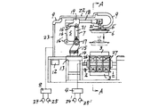
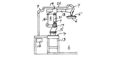
パルプモールド抄造原料2(3%濃度パルプ液)を収容する原料槽1の側部に機台13を設け、その上面に垂直多関節形ロボット5(マニプレーター)の台板14を支持する。該ロボット5の基部15は垂直サーボモータによって垂直中心線cの回りに水平方向に正逆回動自在であって、基部15の上端には平行リンク16を備えた本体7を水平サーボモータ17によって水平共通中心線c’の回りに擺動可能に支持される。
【0008】
平行リンク16の下部横腕16’は上記水平サーボモータ17と共通中心線c’上にある腕用水平サーボモータ17’によって昇降し、上部横腕16”の先端部に接続し、本体7の上端に水平中心線の回りに回動可能な主横腕18の基部嵌合支持筒19を設ける。
【0009】
主横腕18の先端部には終端サーボモータ20を主横腕18の方向と直交する水平回転軸の回りに回動調整可能に設け、終端サーボモータ20の出力軸に接続した支持管21に吸排気函6’を設け、該吸排気函6’の下面開口部に中空雄型6を気密に設け、該雄形6には複数の吸排気小孔6”が穿設してある。
【0010】
吸排気函6’の上部に連通する支持管21にはエヤホース9を接続し、これを主横腕18に沿って設けた横向配管22に接続し、さらに本体7の外側に立設した直立配管23と横向配管22とをエヤホース9で接続し、該横向配管22を切換弁8を介してコンプレッサ24及びバキュームポンプ25に接続する。
【0011】
原料槽1内のパルプモールド抄造原料2の液面上に水平間歇回転軸26を架設し、該回転軸26の上下にスポーク板27、27を介して上向及び下向中空雌型3、3を回転軸26の上下に設け、一方の中空雌型3が原料2に浸漬した状態で中空雌型3内面にパルプモールドを抄造し、回転軸26を中心に180度上下に回動して上向となった中空雌型3内に上記ロボット5の先端に設けた上記中空雄型6を挿入嵌合し、雌型3による吸引を停止すると同時に雄型6を吸引状態とすることによって雌型3の抄造パルプモールド10を雄型6側に吸着して受渡される。
【0012】
中空雌型3には図5に示すように吸引管28及び吹出管29を設け、水平間歇回転軸26の外周部に吸引、吹出のタイミング切換弁30を設け、上記回転軸(中空部)26から吸引、吸引停止、吹出を行い吸引、吹出は機外に設けたコンプレッサ24’及びバキュームポンプ25’(図示していない)によって行う。
【0013】
又中空雌型3はモールド原料2の内部で上向のままパルプを抄造吸着し、その状態で垂直案内ガイドに沿ってモールド原料2の上方の一定水準に回転カム又はシリンダー等の昇降駆動装置によって直線状に昇降させることができる(図示していない)。
【0014】
下向中空雄型6に受渡された抄造パルプモールド10は上記ロボット5の動作によって図3実線位置に上昇し、さらに図4に示すように該中空雄型6は垂直中心線の回りに水平方向に90度回動して停止し、図2に示すように原料槽1の近傍に設けた間歇水平移動キャリヤ11(間歇水平金網コンベヤ、同ベルトコンベヤ、同パレットコンベヤ等)上に本体7を中心に主横腕18が回動し、その状態で中空雄型6をさらに90度回動し上記中空雄型6は上記キャリヤ11上約300mm水準で一旦停止し、監視員が抄造パルプモールド10の状態を点検した後キャリヤ11の約2.5mm上に停止、その水準で切換弁8が吹出し側に切換えられて抄造パルプモールド10は中空雄型6から離れ上記キャリヤ11上に取卸され、搬出される動作を繰返す(図6)。中空雄型6が上述のように(図7、図8、図9)90度回動するのはロボット5、5を原料槽1の両側に2台用いた場合、中空雄型6、6の干渉を避けるためである。
【0015】
上述の動作はシーケンスによるプログラム制御装置12に設定されたプログラムに基づいて順次行われるものである。
【0016】
尚図2中11’で示すものは上記キャリヤの間歇回動チエン、図1中31はバランサーである。
【0017】
【発明の効果】
本発明は上述のようにパルプ槽の一側又は両側機台上に垂直多関節形ロボットを配設し、先端に中空雄型を設け、該雌雄にパルプを抄造した中空雌型を嵌合し、同時吹出吸引によって雌型から雄型に受渡し得るばかりでなく、上記ロボットの作用によって中空雄型を中空雌型との共通中心線に沿って昇降させかつ昇降距離を高く調整し得てモールド成形品の深さを深く抄造し得るため便器などの大形商品全体をカバーする高さの高いクッションカバーや深い包装容器を製造し得る効果がある。
【図面の簡単な説明】
【図1】本発明の大形モールド製品抄造装置を示す正面図である。
【図2】図1の平面図である。
【図3】中空雄型の昇降状態の正面図である。
【図4】中空雄型を90度回動させた状態の正面図である。
【図5】パルプ槽内の中空雌型であって図3A−A線による縦断正面図である。
【図6】停止キャリヤ上に抄造モールドを吹出した状態の正面図である。
【図7】中空雄型の90度回動状態の平面図である。
【図8】主横腕をキャリヤ上に回動し中空雄型を90度回動状態の平面図である。
【図9】主横腕の先端及び中空雄型をキャリヤ上に下降した状態の平面図である。
【符号の説明】
1 原料槽
2 パルプモールド抄造原料
3 中空雌型
4 エヤ吸引排出切換装置
5 垂直多関節形ロボット
6 中空雄型
7 本体
8 エヤ吸引排出切換装置
9 エヤホース
10 抄造パルプモールド
11 間歇水平移動キャリヤ
12 プログラム制御装置[0001]
TECHNICAL FIELD OF THE INVENTION
BACKGROUND OF THE
[0002]
[Prior art]
Conventionally, a large-sized molded product making apparatus (Japanese Patent Publication No. Hei 8-19640) has been developed to produce large-sized molded products such as cushioning materials for toilet bowls having a depth of about 100 to 150 mm and a wall thickness of 5 to 6 mm. Could be done.
[0003]
However, the vertical ascent / descent distance of the hollow male mold is limited to the height distance between the hollow male mold provided on the sliding frame on the horizontal rail and the hollow female mold stopped at a certain level below the same. The depth of the molded product is limited.
[0004]
In order to increase the above depth of the molded product, it is necessary to remove all the height of the horizontal rail, the size of the vertical cylinder supporting the hollow male mold, the elevating guide, etc. from the machine frame, and start again from the design, or the equipment itself Need to be established separately.
[0005]
[Problems to be solved by the invention]
An object of the present invention is to mass-produce a deep molded product by largely adjusting the depth of the molded product by a large-sized molded product making apparatus.
[0006]
[Means for Solving the Problems]
In order to achieve the above object, the present invention connects an air suction / discharge switching device to an elevating hollow female mold that enters and exits the pulp mold papermaking raw material in the raw material tank, and horizontally moves the base near the raw material tank around a vertical center line. A vertical articulated robot provided to be able to rotate forward and backward in the direction is supported so that the main body provided with a parallel link at the upper end of the base can be slid around a horizontal center line, and at the upper end of the main body around the horizontal center line. An air hose having a rotatable main horizontal arm base fitting support cylinder , a hollow male mold provided at the tip of the main horizontal arm, and an air suction / discharge switching device extending along the robot to the robot tip. Connected to the hollow male mold, the hollow female mold facing upward and the hollow male mold facing downward match the papermaking pulp mold by the hollow female mold to the hollow male mold, and on the intermittent horizontal moving carrier provided near the raw material tank The papermaking pulp mold from the hollow male mold The mold product sheeting device lifting hollow female mold according to the first aspect of the present invention is formed so as to be passed and provided with a program control device for the above-mentioned operation, and the hollow female mold lifting and lowering by 180 degrees is driven by vertical lifting. And a molded product papermaking apparatus according to the first aspect of the present invention.
[0007]
BEST MODE FOR CARRYING OUT THE INVENTION
A
[0008]
The lower horizontal arm 16 'of the
[0009]
A
[0010]
An
[0011]
A horizontal intermittent
[0012]
As shown in FIG. 5, the hollow
[0013]
Further, the hollow
[0014]
The
[0015]
The above operations are sequentially performed based on a program set in the
[0016]
The reference numeral 11 'in FIG. 2 denotes an intermittent rotation chain of the carrier, and the
[0017]
【The invention's effect】
The present invention arranges a vertical articulated robot on one side or both sides of the pulp tank as described above, provides a hollow male mold at the tip, and fits a hollow female mold made of pulp into the male and female. In addition to being able to transfer from a female mold to a male mold by simultaneous blowing suction, the mold can be formed by raising and lowering the hollow male mold along the common center line with the hollow female mold by the action of the above robot, and adjusting the vertical distance to be high. Since the depth of the product can be deeply machined, there is an effect that a high cushion cover or a deep packaging container covering the entire large product such as a toilet bowl can be manufactured.
[Brief description of the drawings]
FIG. 1 is a front view showing a large-sized molded product forming apparatus of the present invention.
FIG. 2 is a plan view of FIG.
FIG. 3 is a front view of the hollow male mold in an elevating state.
FIG. 4 is a front view of a state in which the hollow male mold is rotated by 90 degrees.
FIG. 5 is a longitudinal sectional front view of the hollow female mold in the pulp tank taken along the line AA of FIG. 3;
FIG. 6 is a front view of a state in which a papermaking mold is blown onto a stop carrier.
FIG. 7 is a plan view of a hollow male mold in a 90-degree rotation state.
FIG. 8 is a plan view showing a state in which the main horizontal arm is turned on the carrier and the hollow male mold is turned by 90 degrees.
FIG. 9 is a plan view showing a state where the tip of the main horizontal arm and the hollow male mold are lowered onto the carrier.
[Explanation of symbols]
REFERENCE SIGNS
Claims (3)
Priority Applications (1)
| Application Number | Priority Date | Filing Date | Title |
|---|---|---|---|
| JP24272696A JP3550468B2 (en) | 1996-09-13 | 1996-09-13 | Mold product paper making equipment |
Applications Claiming Priority (1)
| Application Number | Priority Date | Filing Date | Title |
|---|---|---|---|
| JP24272696A JP3550468B2 (en) | 1996-09-13 | 1996-09-13 | Mold product paper making equipment |
Publications (2)
| Publication Number | Publication Date |
|---|---|
| JPH1088500A JPH1088500A (en) | 1998-04-07 |
| JP3550468B2 true JP3550468B2 (en) | 2004-08-04 |
Family
ID=17093340
Family Applications (1)
| Application Number | Title | Priority Date | Filing Date |
|---|---|---|---|
| JP24272696A Expired - Fee Related JP3550468B2 (en) | 1996-09-13 | 1996-09-13 | Mold product paper making equipment |
Country Status (1)
| Country | Link |
|---|---|
| JP (1) | JP3550468B2 (en) |
Families Citing this family (11)
| Publication number | Priority date | Publication date | Assignee | Title |
|---|---|---|---|---|
| KR100295090B1 (en) * | 1999-01-12 | 2001-07-03 | 허일권 | An adult form pulp mold system |
| GB2443981B (en) * | 2004-04-01 | 2008-09-03 | Honda Motor Co Ltd | Simulation apparatus |
| US20100261014A1 (en) * | 2004-04-14 | 2010-10-14 | Geiger Jr Ervin | Utilization of recycled carbon fiber |
| SE529164C2 (en) | 2004-11-26 | 2007-05-22 | Pakit Int Trading Co Inc | Pulp form and use of pulp form |
| SE528685C2 (en) * | 2004-11-26 | 2007-01-23 | Pakit Int Trading Co Inc | Method and machine for making fiber products of stock |
| SE529627C2 (en) | 2006-01-18 | 2007-10-09 | Pakit Int Trading Co Inc | Molding tools for the production of fiber articles |
| IS2688B (en) * | 2007-10-31 | 2010-10-15 | Graenar Lausnir Ehf | Process for producing large parts of cardboard pulp |
| CN109537369A (en) * | 2019-01-16 | 2019-03-29 | 东莞三润田智能科技股份有限公司 | Ecological vegetable fibre pulp Dining tool and work packet automatic assembly line |
| CN109677862A (en) * | 2019-01-16 | 2019-04-26 | 东莞三润田智能科技股份有限公司 | Ecological vegetable fibre pulp Dining tool and work packet automatic manufacturing method |
| CN112813736B (en) * | 2019-11-18 | 2022-12-06 | 浙江舒康科技有限公司 | Robot forming flexible production line and forming method for paper pulp molded product |
| WO2023102828A1 (en) * | 2021-12-09 | 2023-06-15 | 巢邕 | Paper pulp fiber composite molding device |
-
1996
- 1996-09-13 JP JP24272696A patent/JP3550468B2/en not_active Expired - Fee Related
Also Published As
| Publication number | Publication date |
|---|---|
| JPH1088500A (en) | 1998-04-07 |
Similar Documents
| Publication | Publication Date | Title |
|---|---|---|
| JP3550468B2 (en) | Mold product paper making equipment | |
| KR100838875B1 (en) | Die molding machine and pattern carrier | |
| EP2604362A2 (en) | Mold molding device and mold molding method | |
| WO2001032333A1 (en) | Molding device and molding method or sand mold | |
| CN107235165B (en) | Full-automatic boxing device of injection molding machine | |
| EP0412533B1 (en) | Slip casting device | |
| CN107322782B (en) | Automatic overturning and conveying device for high-pressure formed green body of toilet | |
| CN206840808U (en) | Disjunctor renovates medicine box automatic moulding machine | |
| KR100949621B1 (en) | Apparatus for molding molding flask-free upper casting mold and lower casting mold | |
| JPH0999457A (en) | Injection molding taking-out machine | |
| CN113859660A (en) | Full-automatic rhinestone film-covering plastic-absorbing machine | |
| CN113146830A (en) | Intelligent conjoined robot workstation for high-pressure grouting of toilet bowl | |
| JPS588629A (en) | Tire removing apparatus | |
| CN212982768U (en) | Rotary processing type glass bottle mold | |
| CN113427619B (en) | Shield tunnel segment intelligent production line and using method thereof | |
| JP4631146B2 (en) | Cleaning device for filling nozzle | |
| CN110269802B (en) | Capsule production line | |
| CN113844714A (en) | Full-automatic ton bag packaging machine | |
| KR100498009B1 (en) | Pulp mold system for exclusive using food receptacle | |
| CN110654063A (en) | Internal mold defoaming machine and internal mold defoaming process | |
| CN218699983U (en) | Auxiliary mold opening device of ceramic grouting mold | |
| CN216186447U (en) | Intelligent detection carton adjusting system | |
| KR101598527B1 (en) | Transfer apparatus of food | |
| CN216378936U (en) | Transfer type paper mold production line with joint robot and net | |
| JP2003165147A (en) | Demolding device for injection molding machine |
Legal Events
| Date | Code | Title | Description |
|---|---|---|---|
| A131 | Notification of reasons for refusal |
Free format text: JAPANESE INTERMEDIATE CODE: A131 Effective date: 20040106 |
|
| A521 | Written amendment |
Free format text: JAPANESE INTERMEDIATE CODE: A523 Effective date: 20040210 |
|
| TRDD | Decision of grant or rejection written | ||
| A01 | Written decision to grant a patent or to grant a registration (utility model) |
Free format text: JAPANESE INTERMEDIATE CODE: A01 Effective date: 20040330 |
|
| A61 | First payment of annual fees (during grant procedure) |
Free format text: JAPANESE INTERMEDIATE CODE: A61 Effective date: 20040426 |
|
| R150 | Certificate of patent or registration of utility model |
Free format text: JAPANESE INTERMEDIATE CODE: R150 |
|
| R250 | Receipt of annual fees |
Free format text: JAPANESE INTERMEDIATE CODE: R250 |
|
| FPAY | Renewal fee payment (event date is renewal date of database) |
Free format text: PAYMENT UNTIL: 20090430 Year of fee payment: 5 |
|
| FPAY | Renewal fee payment (event date is renewal date of database) |
Free format text: PAYMENT UNTIL: 20100430 Year of fee payment: 6 |
|
| FPAY | Renewal fee payment (event date is renewal date of database) |
Free format text: PAYMENT UNTIL: 20110430 Year of fee payment: 7 |
|
| FPAY | Renewal fee payment (event date is renewal date of database) |
Free format text: PAYMENT UNTIL: 20130430 Year of fee payment: 9 |
|
| FPAY | Renewal fee payment (event date is renewal date of database) |
Free format text: PAYMENT UNTIL: 20140430 Year of fee payment: 10 |
|
| R250 | Receipt of annual fees |
Free format text: JAPANESE INTERMEDIATE CODE: R250 |
|
| LAPS | Cancellation because of no payment of annual fees |