【0001】
【発明の属する技術分野】
この発明は、鋼管矢板を製造する際に、鋼管に継手を取り付ける鋼管矢板の継手取付装置に関する。
【0002】
【従来の技術】
港湾の護岸等に使用される鋼管矢板41は、図12(a)に示すように、スパイラル鋼管42の外周面の180度離れた2箇所に、軸芯がスパイラル鋼管42の軸芯と平行となるように切り欠き部のある2個のパイプ状の継手、または一方にT字状継手他方にL字状の継手43を溶接している。そして、これらの継手43に他の鋼管矢板41の継手43を嵌め合わせ、鋼管矢板41を複数接続した状態で使用される。
【0003】
したがって、同一鋼管矢板41に設けられる2個の継手は、雄と雌の関係にあり、一般に図12(b)に示すように、スパイラル鋼管42に切り欠き部を有するパイプ状の継手43aをその切り欠き部が反対方向を向くように取り付けるか、図12(c)に示すように、スパイラル鋼管42に一方はT字形の継手43bを、他方は2本のL字形継手43cを隙間を空けて取り付けるようにしている。
【0004】
このような鋼管矢板41を製造する場合に、スパイラル鋼管42への継手43の取り付け方法は、パイプ状継手の場合で説明すると、従来次のような手順で行っている。
(1)スパイラル鋼管の周方向180度離れた位置の外周面に、スパイラル鋼管の軸線と平行に、継手取り付け予定位置を示す2本の罫書き線を罫書く。
(2)罫書き線を罫書いたスパイラル鋼管を、タ−ニングロ−ラ上に置き、タ−ニングロ−ラを回転させて、罫書き線の一つがスパイラル鋼管の真上に位置するようにする。
(3)継手をクレ−ンで吊って、スパイラル鋼管の真上に載せる。
(4)ハンマ−等で継手をたたきながら、継手の軸線と罫書き線とが一致するようにする。
(5)継手とスパイラル鋼管を複数箇所溶接して仮止めする。
(6)本溶接を行う。
【0005】
【発明が解決しようとする課題】
しかしながら、上述した従来の鋼管矢板製造におけるスパイラル鋼管への継手の取り付け方法には、次のような問題点がある。
(1)仮止めを必要とするので、製造能率が悪い。
(2)鋼管矢板の本体部分にスパイラル鋼管を使用するのが一般的であるので、スパイラル鋼管特有のうねりがスパイラル鋼管の表面に存在し、スパイラル鋼管と継手との間に隙間が生じ、この隙間を溶接で埋めるために高い入熱量を必要とするので、溶接能率が低下するとともに、溶接欠陥が発生しやすい。
【0006】
この発明は、従来技術の上述のような問題点を解消するためになされたものであり、高能率で溶接することが可能であり、かつ溶接欠陥も発生しない鋼管矢板の継手取付装置を提供することを目的としている。
【0007】
【課題を解決するための手段】
本発明の課題は以下の手段により解決される。
1 継手取り付け中にスパイラル鋼管を支持し且つ継手取り付け予定位置がスパイラル鋼管の真上にくるように位置調整するターニングローラと、ターニングローラ上の前記スパイラル鋼管の継手取り付け予定位置に前記継手を搬送し、軸線がスパイラル鋼管の軸線と平行になるように位置調整した後、継手をスパイラル鋼管表面上に固定する2台の搬送クレーンと、スパイラル鋼管の軸線方向に走行し、継手とスパイラル鋼管の接触部分を両側から溶接する溶接装置および継手を押し付けてスパイラル鋼管との間の隙間をなくす押さえ装置を搭載した溶接台車とからなり、前記溶接台車の溶接装置はスパイラル鋼管表面の凹凸にしたがって位置が変化する倣いガイド円板に接続されているガイドに取り付けられていることを特徴とするスパイラル鋼管矢板の継手取付装置。
【0008】
この発明に係る鋼管矢板の継手取付装置を使用して、継手を取り付ける場合には、2台の搬送クレ−ンにより、継手を正確に鋼管上の取り付け予定位置に位置させることができる。
【0009】
そして、溶接中には鋼管表面のうねりに倣って継手を押し付け、鋼管と継手との隙間がなくなるようにして溶接することができる。
【0010】
したがって、継手の位置決めに時間がかからないとともに、鋼管と継手との隙間がないので、溶接時の入熱量が少なくてすみ、高速溶接が可能である上に、溶接欠陥が発生しにくい。
【0011】
【発明の実施の形態】
以下、添付図面を参照して本発明の実施の形態について説明する。
【0012】
図1はこの発明の実施の形態の鋼管矢板の継手取付装置の構成を示す平面図である。
【0013】
この鋼管矢板の継手取付装置は、継手43を取り付け中に鋼管42を支持し、かつ継手取り付け予定位置が鋼管42の真上にくるように位置調整するタ−ニングロ−ラ1と、タ−ニングロ−ラ1上の前記鋼管42の継手取り付け予定位置に前記継手43を搬送し、軸線が鋼管42の軸線と平行になるように位置調整した後継手43を鋼管表面上に固定する2台の搬送クレ−ン2および3と、鋼管42の軸線方向に走行し、継手43と鋼管42の接触部分を両側から溶接する溶接装置および継手を押し付けて鋼管との間の隙間をなくす押さえ装置を搭載した溶接台車4とから構成されている。
【0014】
図1において、符号5は鋼管置場であり、鋼管42は鋼管置場5から跳ね出し装置(図示せず)により、タ−ニングロ−ラ1上に跳ね出される。
【0015】
また、符号6は継手置場であり、ここに運び込まれた継手43は、チェ−ンコンベア7により、2台の搬送クレ−ン2および3で搬送可能な位置まで横送りされる。そして、継手43は2台の搬送クレ−ン2および3により、タ−ニングロ−ラ1上の鋼管42のところまで搬送される。
【0016】
上述した鋼管矢板の継手取付装置を詳述すると、次のとおりである。
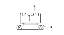
図2の側面図に示すように、前記チェ−ンコンベア7のリンクチェ−ン8には、継手43を搬送クレ−ン2および3で吊り上げるときに、容易に吊り上げできるように、継手43を受ける受け金具9が組み込まれている。
【0017】
そして、パイプ状継手43aは図3(a)に示すように、T字状継手43bは図3(b)に示すように受け金具9上に置かれており、またL字状継手43cは図3(c)に示すように、2本のL字状継手43cが連結バ−10で連結された状態で置かれている。
【0018】
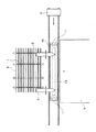
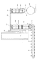
搬送クレ−ン2および3は、図4の正面図に示すように、継手置場6のチェ−ンコンベア7の搬送方向と直交する方向、すなわち鋼管42の軸線と平行な方向にクレ−ンガ−ダ−11上を走行するクレ−ン本体12と、クレ−ン本体12の走行方向と直交し鋼管42に向かうように、クレ−ン本体12に取り付けられた横行レ−ル13と、横行レ−ル13上を走行するやぐら状をした横行装置14と、横行装置14に設けられ、チェ−ンコンベア7の受け金具9上に置かれた継手43を掴み上げる継手掴み装置15と、継手掴み装置15をチェ−ン16を介して巻き上げるホイスト17と、図示していないが搬送クレ−ン2および3の走行位置、横行位置および巻き上げ位置を検出するためのエンコ−ダ−とから構成されている。
【0019】
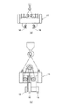
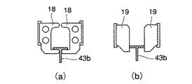
上述した継手掴み装置15は、図5(a)の正面図および図5(b)の側面図に示すように、継手43を掴み上げるためのクランプ爪18と、掴み上げた継手43(図6(a)(b)では43bで示す)のセンタ−リングを行うためのセンタ−リング用爪19が設けられている。
【0020】
そして、前述した受け金具9上の継手43を、図6(a)に示すように、クランプ爪18で下から抱え込むように掴むとともに、クランプ爪18で掴んだ後の継手43のセンタ−リングを、図6(b)に示すように、センタ−リング用爪19で行う。
【0021】
センタ−リングを行った後の継手43は、ホイスト17で巻き上げられ、鋼管42の上まで搬送され、鋼管42の外周面に罫書かれた継手取り付け予定位置を示す罫書き線に基づいて位置合わせを行った後、搬送クレ−ン2および3の2台の継手掴み装置15で掴まれた状態で、鋼管42上に押し付けられる。
【0022】
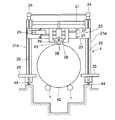
次に、溶接台車4を説明する。この溶接台車4は、図7に示すように、タ−ニングロ−ラ1上に置かれた鋼管42の両側かつ長手方向に沿って配置されているレ−ル44上を走行するものであり、基板20の上面には門型フレ−ム21が設けられている。この門型フレ−ム21の2本の垂直部21aのそれぞれと平行して2本のスクリュウシャフト22が設けられており、この2本のスクリュウシャフト22に昇降基板23が螺合されている。そして、駆動装置24により2本のスクリュウシャフト22を回転させて、昇降基板23を昇降させることができる。
【0023】
また、昇降基板23上には横行基板25が設けられており、駆動装置26によりレ−ル27に沿って水平方向に移動できるようになっている。
【0024】
この横行基板25には、継手43を上方から押さえ付ける押さえロ−ラ−28や、継手43を両側面からガイドするガイドロ−ラ−29が設けられている。そして、これらの押さえロ−ラ−28やガイドロ−ラ−29はの位置は、鋼管42や継手43の大きさにより、前記昇降基板23や横行基板25を移動させて調整される。
【0025】
また、図7には図示されていないが、横行基板25上には鋼管42と継手43の接触部分を両側から溶接する2台の溶接装置が設けられている。
【0026】
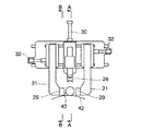
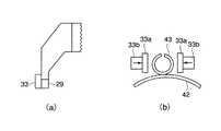
図8は横行基板25上に設けられた押さえロ−ラ−28やガイドロ−ラ−29を示す正面図である。押さえロ−ラ−28は油圧シリンダ−30により鋼管42上の継手43上面に押し付けられる。また、左右のガイドロ−ラ−29は、それぞれを取り付けたブラケット31を、油圧シリンダ−32で移動させることにより、継手43の側面に押し付けられる。
【0027】
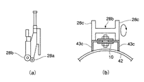
図9(a)は図8のA−A矢視図であり、この図から分かるように押さえロ−ラ−28は2個ある。第1の押さえロ−ラ−28aは円筒状をしており、パイプ状継手43aやT字状継手43bの場合に使用される。第2の押さえロ−ラ−28bは図9(b)に示すように両端につば部28cのある円筒ロ−ラ−であり、L字状継手43cの場合のように、2本のL字状継手43c間の連結バ−10がじゃまになるときに使用される。
【0028】
図10(a)は図8のB−B矢視図であり、この図から分かるようにブラケット31にはガイドロ−ラ−29に加えて、センタリング治具33が取り付けられている。センタリング治具33は図10(b)に示すように、センタリング板33aとエア−シリンダ−33bとから構成されており、エア−シリンダ−33bによりセンタリング板33aを継手43の両側面から当てて、継手43のセンタ−リングを行ない、その後ガイドロ−ラ−29でガイドするようになっている。
【0029】
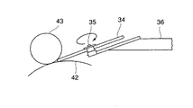
本発明の鋼管矢板の継手取付装置においては、上述したように押さえロ−ラ−28やガイドロ−ラ−29で継手43をガイドしながら溶接するのであるが、これらの押さえロ−ラ−28やガイドロ−ラ−29よりも進行方向後方の位置に、図11に示すような倣いガイド円板34が、鋼管42と継手43の接触部分の両側(図11では片側しか示していない)に押し付けられた状態で配置してある。
【0030】
この倣いガイド円板34は、回転軸35の回りに回転しながら溶接台車4とともに前進するが、倣いガイド円板34に接続されたガイド36上には、溶接ト−チを含む溶接装置が搭載されている。ガイド36には、倣いガイド円板34が鋼管42と継手43の接触部分から離れないように、エア−シリンダ−により水平方向および垂直方向に空気圧が常に作用しているように構成されている。したがって、倣いガイド円板34の位置は、鋼管42の表面の凹凸にしたがって変化する。このためガイド36に搭載された溶接ト−チの位置もまた鋼管42の表面の凹凸にしたがって変化する上に、継手43と鋼管42との隙間も押さえロ−ラ−28により一定に保たれているので、溶接開始時点で溶接ト−チの位置を適正に調整しておけば、溶接ト−チと溶接部位との間の距離および溶接ト−チの方向が常に適正に保たれることになる。なお、溶接ト−チの位置調整は位置調整駆動機構により行うことができるようになっている。
【0031】
前述したように、継手43は、搬送クレ−ン2および3に搭載した継手掴み装置15により、鋼管42に押し付けられているが、溶接台車4が前進して押さえロ−ラ−28やガイドロ−ラ−29が当たりそうになる直前に、継手掴み装置15は退避するようになっている。
【0032】
本発明の鋼管矢板の継手取付装置を使用すると、鋼管矢板の継手を上述のようにして取り付けることができるので、継手の位置決めに時間がかからないとともに、鋼管と継手との隙間がないので、溶接時の入熱量が少なくてすみ、高速溶接が可能である。さらには、溶接欠陥の発生も少なくなる。
【0033】
【発明の効果】
この発明により、鋼管矢板の継手の取り付けを、高能率で行えるとともに、溶接欠陥の発生も低減させることができる。
【図面の簡単な説明】
【図1】この発明の実施の形態の鋼管矢板の継手取付装置の構成を示す平面図である。
【図2】リンクチェ−ンに組み込んだ受け金具の側面図である。
【図3】受け金具に継手を搭載した状態を示す側面図であり、(a)はパイプ状継手を、(b)はT字状継手を、(c)はL字状継手を搭載した状態を示す。
【図4】搬送クレ−ンの正面図である。
【図5】搬送クレ−ンの継手掴み装置の説明図であり、(a)は正面図、(b)は側面図である。
【図6】搬送クレ−ンの継手掴み装置で継手を掴んだ状態を示す側面図であり、(a)はクランプ爪で継手を抱え込んだ状態を、(b)はセンタ−リング用爪で継手のセンタ−リングを行っている状態を示す。
【図7】溶接台車の正面図である。
【図8】横行基板上に設けられた押さえロ−ラ−やガイドロ−ラ−を示す正面図である。
【図9】(a)は図8のA−A矢視図であり、(b)は第二の押さえロ−ラ−の正面図である。
【図10】(a)は図8のB−B矢視図であり、(b)はセンタリング治具の構成を示す正面図である。
【図11】倣いガイド円板の正面図である。
【図12】鋼管矢板の説明図であり、(a)は鋼管矢板を示す正面図、(b)は継手がパイプ状継手同士の場合の鋼管矢板の側面図、(c)は継手がT字状継手とL字状継手との組み合わせの場合の鋼管矢板の側面図である。
【符号の説明】
1 タ−ニングロ−ラ
2 搬送クレ−ン
3 搬送クレ−ン
4 溶接台車
5 鋼管置場
6 継手置場
7 チェ−ンコンベア
8 リンクチェ−ン
9 受け金具
10 連結バ−
11 クレ−ンガ−ダ−
12 クレ−ン
13 横行レ−ル
14 横行装置
15 継手掴み装置
16 チェ−ン
17 ホイスト17
18 クランプ爪
19 センタ−リング用爪
20 基板
21 門型フレ−ム
22 スクリュウシャフト
23 昇降基板
24 駆動装置
25 横行基板
26 駆動装置
27 レ−ル
28 押さえロ−ラ−
28a 第一の押さえロ−ラ−
28b 第二の押さえロ−ラ−
29 ガイドロ−ラ−
30 油圧シリンダ−
31 ブラケット
32 油圧シリンダ−
33 センタリング治具
33a センタリング板
33b エア−シリンダ−
34 倣いガイド円板
35 回転軸
36 ガイド[0001]
TECHNICAL FIELD OF THE INVENTION
TECHNICAL FIELD The present invention relates to a steel pipe sheet pile joint mounting device for mounting a steel pipe pile when manufacturing a steel pipe sheet pile.
[0002]
[Prior art]
As shown in FIG. 12A, the steel pipe sheet pile 41 used for seawall protection of a harbor has a shaft center parallel to the spiral steel pipe 42 at two places 180 degrees apart on the outer peripheral surface of the spiral steel pipe 42. Two pipe-shaped joints having notches or a T-shaped joint on one side and an L-shaped joint 43 on the other side are welded. Then, the joint 43 of another steel pipe sheet pile 41 is fitted to these joints 43, and the steel pipe sheet pile 41 is used in a state where a plurality of steel pipe sheet piles 41 are connected.
[0003]
Therefore, the two joints provided on the same steel pipe sheet pile 41 are in a male-female relationship, and generally, as shown in FIG. 12B, a spiral-shaped steel pipe 42 has a pipe-shaped joint 43a having a notch. 12 (c), one of the spiral steel pipes 42 is provided with a T-shaped joint 43b, and the other is provided with two L-shaped joints 43c with a gap therebetween, as shown in FIG. 12 (c). I try to attach it.
[0004]
When manufacturing such a steel pipe sheet pile 41, the method of attaching the joint 43 to the spiral steel pipe 42 will be described in the following in the case of a pipe-shaped joint.
(1) On the outer circumferential surface of the spiral steel pipe at a position 180 degrees apart in the circumferential direction, two score lines are drawn in parallel with the axis of the spiral steel pipe, indicating the planned joint installation position.
(2) The spiral steel pipe having the scored line is placed on a turning roller, and the turning roller is rotated so that one of the scored lines is located directly above the spiral steel pipe. .
(3) Hang the joint with a crane and place it directly above the spiral steel pipe.
(4) While hitting the joint with a hammer or the like, make sure that the axis of the joint coincides with the scribe line.
(5) The joint and the spiral steel pipe are welded at a plurality of locations and temporarily fixed.
(6) Perform main welding.
[0005]
[Problems to be solved by the invention]
However, the above-mentioned conventional method of attaching a joint to a spiral steel pipe in the manufacture of sheet piles has the following problems.
(1) Production efficiency is poor because temporary fixing is required.
(2) Since a spiral steel pipe is generally used for the main part of a steel sheet pile, a undulation peculiar to the spiral steel pipe is present on the surface of the spiral steel pipe, and a gap is generated between the spiral steel pipe and a joint. Therefore, a high heat input is required to fill the gap with welding, so that welding efficiency is reduced and welding defects are easily generated.
[0006]
SUMMARY OF THE INVENTION The present invention has been made to solve the above-mentioned problems of the prior art, and provides a joint installation device for a steel pipe sheet pile that can be welded with high efficiency and that does not generate welding defects. It is aimed at.
[0007]
[Means for Solving the Problems]
The object of the present invention is solved by the following means.
(1) A turning roller for supporting the spiral steel pipe during installation of the joint and adjusting the position so that the joint installation position is right above the spiral steel pipe, and transferring the joint to the joint installation position of the spiral steel pipe on the turning roller. After adjusting the position so that the axis is parallel to the axis of the spiral steel pipe, two transport cranes that fix the joint on the surface of the spiral steel pipe, and traveling in the axial direction of the spiral steel pipe, and the contact part between the joint and the spiral steel pipe A welding bogie equipped with a welding device for welding from both sides and a holding device for pressing a joint to eliminate a gap between the spiral steel tube, and the welding bogie's welding device changes its position according to the unevenness of the surface of the spiral steel tube. A spy mounted on a guide connected to the copying guide disk Ral steel pipe sheet pile joint mounting device.
[0008]
When the joint is mounted by using the steel pipe sheet pile joint mounting apparatus according to the present invention, the joint can be accurately positioned at the planned mounting position on the steel pipe by using two transfer crane.
[0009]
Then, during welding, the joint is pressed in accordance with the undulation of the steel pipe surface, and the welding can be performed such that the gap between the steel pipe and the joint is eliminated.
[0010]
Therefore, the positioning of the joint does not take much time, and there is no gap between the steel pipe and the joint, so that the heat input during welding can be reduced, high-speed welding can be performed, and welding defects are hardly generated.
[0011]
BEST MODE FOR CARRYING OUT THE INVENTION
Hereinafter, embodiments of the present invention will be described with reference to the accompanying drawings.
[0012]
FIG. 1 is a plan view showing a configuration of a steel pipe sheet pile joint mounting device according to an embodiment of the present invention.
[0013]
The joint mounting device for a steel pipe sheet pile includes a turning roller 1 for supporting the steel pipe 42 during the installation of the joint 43 and adjusting the position so that the joint mounting expected position is right above the steel pipe 42, and a turning roller. The two joints for transferring the joint 43 to the joint mounting position of the steel pipe 42 on the roller 1 and adjusting the position of the joint so that the axis is parallel to the axis of the steel pipe 42 and then fixing the joint 43 on the steel pipe surface; The crane 2 and 3 and the welding device which runs in the axial direction of the steel pipe 42 and welds the contact part of the joint 43 and the steel pipe 42 from both sides, and the holding device which presses the joint and eliminates the gap between the steel pipe 42 are installed. And a welding trolley 4.
[0014]
In FIG. 1, reference numeral 5 denotes a steel pipe yard, and a steel pipe 42 is spouted out of the steel pipe yard 5 onto the turning roller 1 by a bouncing device (not shown).
[0015]
Reference numeral 6 denotes a joint storage space. The joint 43 carried here is laterally fed by the chain conveyor 7 to a position where it can be conveyed by the two conveyor crane 2 and 3. Then, the joint 43 is transported to the steel pipe 42 on the turning roller 1 by the two transport crane 2 and 3.
[0016]
The above-described joint mounting device for a steel pipe sheet pile will be described below in detail.
As shown in the side view of FIG. 2, the link chain 8 of the chain conveyor 7 receives the joint 43 so that it can be easily lifted when the joint 43 is lifted by the transfer crane 2 and 3. The receiving fitting 9 is incorporated.
[0017]
3 (a), the T-shaped joint 43b is placed on the receiving fitting 9 as shown in FIG. 3 (b), and the L-shaped joint 43c is As shown in FIG. 3 (c), two L-shaped joints 43c are placed in a state of being connected by a connecting bar 10.
[0018]
As shown in the front view of FIG. 4, the conveying crane 2 and 3 are crane girder in a direction perpendicular to the conveying direction of the chain conveyor 7 of the joint storage 6, that is, in a direction parallel to the axis of the steel pipe 42. -11, a traverse rail 13 attached to the crane body 12 so as to be perpendicular to the traveling direction of the crane body 12 and toward the steel pipe 42, and a traverse rail. A traversing device 14 running in the shape of a ladder, a joint gripping device 15 provided on the traversing device 14 and gripping a joint 43 placed on the receiving fitting 9 of the chain conveyor 7, and a joint gripping device 15. The hoist 17 is wound up through a chain 16 and an encoder (not shown) for detecting the traveling position, traversing position and winding position of the transport crane 2 and 3 is provided.
[0019]
As shown in the front view of FIG. 5 (a) and the side view of FIG. 5 (b), the above-described joint gripping device 15 includes a clamp claw 18 for gripping the joint 43 and a joint 43 (FIG. A centering claw 19 for performing centering of (a) and (b) is indicated by 43b) is provided.
[0020]
Then, as shown in FIG. 6A, the joint 43 on the receiving fitting 9 is gripped by the clamp claw 18 so as to be held from below, and the centering of the joint 43 after being clamped by the clamp claw 18 is performed. 6 (b), the centering claw 19 is used.
[0021]
After the centering is performed, the joint 43 is wound up by the hoist 17, conveyed to a position above the steel pipe 42, and aligned on the basis of a scored line indicating a joint installation scheduled position marked on the outer peripheral surface of the steel pipe 42. After the operation, the transfer crane 2 and 3 are pressed onto the steel pipe 42 while being held by the two joint holding devices 15.
[0022]
Next, the welding cart 4 will be described. As shown in FIG. 7, the welding cart 4 travels on rails 44 arranged on both sides of the steel pipe 42 placed on the turning roller 1 and along the longitudinal direction. A gate-shaped frame 21 is provided on the upper surface of the substrate 20. Two screw shafts 22 are provided in parallel with each of the two vertical portions 21a of the portal frame 21, and an elevating substrate 23 is screwed to the two screw shafts 22. Then, the two screw shafts 22 are rotated by the driving device 24, so that the lifting substrate 23 can be raised and lowered.
[0023]
A traversing substrate 25 is provided on the elevating substrate 23, and can be moved in a horizontal direction along a rail 27 by a driving device 26.
[0024]
The traversing board 25 is provided with a pressing roller 28 for pressing the joint 43 from above, and a guide roller 29 for guiding the joint 43 from both sides. The positions of the holding rollers 28 and the guide rollers 29 are adjusted by moving the lifting board 23 and the traversing board 25 according to the size of the steel pipe 42 and the joint 43.
[0025]
Although not shown in FIG. 7, two welding devices are provided on the traversing substrate 25 to weld the contact portion between the steel pipe 42 and the joint 43 from both sides.
[0026]
FIG. 8 is a front view showing a holding roller 28 and a guide roller 29 provided on the traversing substrate 25. The pressing roller 28 is pressed against the upper surface of the joint 43 on the steel pipe 42 by the hydraulic cylinder 30. The left and right guide rollers 29 are pressed against the side surface of the joint 43 by moving the bracket 31 to which each is attached with the hydraulic cylinder 32.
[0027]
FIG. 9A is a view taken along the line AA of FIG. 8, and as can be seen from this figure, there are two holding rollers 28. The first holding roller 28a has a cylindrical shape and is used in the case of a pipe-shaped joint 43a or a T-shaped joint 43b. The second pressing roller 28b is a cylindrical roller having flanges 28c at both ends as shown in FIG. 9 (b), and has two L-shaped joints as in the case of the L-shaped joint 43c. It is used when the connecting bar 10 between the joints 43c is in the way.
[0028]
FIG. 10A is a view taken in the direction of arrows B-B in FIG. 8. As can be seen from FIG. 10A, a centering jig 33 is attached to the bracket 31 in addition to the guide roller 29. The centering jig 33 is composed of a centering plate 33a and an air-cylinder 33b as shown in FIG. 10B, and the centering jig 33 is brought into contact with both sides of the joint 43 by the air-cylinder 33b. The centering of the joint 43 is performed, and then the guide is guided by a guide roller 29.
[0029]
In the joint mounting apparatus for steel sheet piles according to the present invention, welding is performed while guiding the joint 43 with the holding roller 28 and the guide roller 29 as described above. A copying guide disk 34 as shown in FIG. 11 is pressed against both sides (only one side is shown in FIG. 11) of the contact portion between the steel pipe 42 and the joint 43 at a position behind the guide roller 29 in the traveling direction. It is arranged in the state where it was set.
[0030]
The copying guide disk 34 advances with the welding trolley 4 while rotating around the rotating shaft 35, and a welding device including a welding torch is mounted on a guide 36 connected to the copying guide disk 34. Have been. The guide 36 is configured such that air pressure is constantly applied in the horizontal and vertical directions by an air cylinder so that the copying guide disk 34 does not separate from the contact portion between the steel pipe 42 and the joint 43. Therefore, the position of the copying guide disk 34 changes according to the unevenness of the surface of the steel pipe 42. Therefore, the position of the welding torch mounted on the guide 36 also changes according to the unevenness of the surface of the steel pipe 42, and the gap between the joint 43 and the steel pipe 42 is kept constant by the pressing roller 28. Therefore, if the position of the welding torch is properly adjusted at the start of welding, the distance between the welding torch and the welding site and the direction of the welding torch will always be properly maintained. Become. The position of the welding torch can be adjusted by a position adjusting drive mechanism.
[0031]
As described above, the joint 43 is pressed against the steel pipe 42 by the joint gripping device 15 mounted on the transfer crane 2 and 3, but the welding carriage 4 moves forward to hold down the holding roller 28 and the guide roller. Just before the line 29 is about to hit, the joint gripping device 15 is retracted.
[0032]
When the joint mounting device for a steel pipe sheet pile of the present invention is used, the joint of the steel pipe sheet pile can be mounted as described above. The amount of heat input is small, and high-speed welding is possible. Furthermore, the occurrence of welding defects is reduced.
[0033]
【The invention's effect】
According to the present invention, the joint of the steel pipe sheet pile can be attached with high efficiency, and the occurrence of welding defects can be reduced.
[Brief description of the drawings]
FIG. 1 is a plan view showing a configuration of a steel pipe sheet pile joint mounting device according to an embodiment of the present invention.
FIG. 2 is a side view of a receiving fitting incorporated in a link chain.
FIGS. 3A and 3B are side views showing a state in which a fitting is mounted on a receiving fitting, in which FIG. 3A is a pipe-shaped joint, FIG. 3B is a T-shaped joint, and FIG. Is shown.
FIG. 4 is a front view of the transport crane.
FIGS. 5A and 5B are explanatory diagrams of a joint gripping device for a transfer crane, wherein FIG. 5A is a front view and FIG. 5B is a side view.
FIGS. 6A and 6B are side views showing a state in which the joint is gripped by the joint gripping device of the transfer crane, wherein FIG. 6A shows a state in which the joint is held by clamp claws, and FIG. 3 shows a state in which centering is being performed.
FIG. 7 is a front view of the welding cart.
FIG. 8 is a front view showing a pressing roller and a guide roller provided on the traversing substrate.
9A is a view taken in the direction of arrows AA in FIG. 8, and FIG. 9B is a front view of a second pressing roller.
10 (a) is a view taken in the direction of arrows BB in FIG. 8, and FIG. 10 (b) is a front view showing a configuration of a centering jig.
FIG. 11 is a front view of the copying guide disk.
12A and 12B are explanatory views of a steel sheet pile, (a) is a front view showing the steel pipe sheet pile, (b) is a side view of the steel pipe sheet pile when the joints are pipe-like joints, and (c) is a T-shaped joint. It is a side view of the steel pipe sheet pile in the case of the combination of a shape joint and an L-shaped joint.
[Explanation of symbols]
DESCRIPTION OF SYMBOLS 1 Turning roller 2 Conveyor crane 3 Conveyor crane 4 Welding trolley 5 Steel pipe yard 6 Joint yard 7 Chain conveyor 8 Link chain 9 Receiving bracket 10 Connection bar
11 Crane guarder
12 Crane 13 Traversing rail 14 Traversing device 15 Joint gripping device 16 Chain 17 Hoist 17
18 Clamping Claw 19 Centering Claw 20 Substrate 21 Gate Frame 22 Screw Shaft 23 Elevating Substrate 24 Driving Device 25 Traversing Substrate 26 Driving Device 27 Rail 28 Holding Roller
28a First holding roller
28b Second holding roller
29 Guide Roller
30 Hydraulic cylinder
31 Bracket 32 Hydraulic cylinder
33 Centering jig 33a Centering plate 33b Air-cylinder
34 Copying guide disk 35 Rotation axis 36 Guide