JP3139367U - Reclining seat and reclining seat type wheelchair - Google Patents
Reclining seat and reclining seat type wheelchair Download PDFInfo
- Publication number
- JP3139367U JP3139367U JP2007009171U JP2007009171U JP3139367U JP 3139367 U JP3139367 U JP 3139367U JP 2007009171 U JP2007009171 U JP 2007009171U JP 2007009171 U JP2007009171 U JP 2007009171U JP 3139367 U JP3139367 U JP 3139367U
- Authority
- JP
- Japan
- Prior art keywords
- fulcrum
- link arm
- frame
- seat
- link
- Prior art date
- Legal status (The legal status is an assumption and is not a legal conclusion. Google has not performed a legal analysis and makes no representation as to the accuracy of the status listed.)
- Expired - Lifetime
Links
Images


Abstract
【課題】背フレームの回動軸心を着座者の腰部に位置する仮想支点を中心として回動させることにより、背フレームの回動による着座者とのずれを防止するリクライニングシートを得る。
【解決手段】座フレーム7を支持する取り付けフレーム6に第1支点P1とこれよりも後方かつ上方に位置する第2支点P2を設け、背フレーム8の下部に第6支点P6とこれよりも後方かつ上方に位置する第7支点P7を設け、第1支点P1及び第2支点P2に第1リンクアームL1及び第2リンクアームL2を後方に向けて回動可能に連結し、第6支点P6及び第7支点P7に第3リンクアームL3及び第4リンクアームL4を下方に向けて回動可能に連結し、第1リンクアームL1の後部と第2リンクアームL2の前後方向中間部とに、第1支点P1、第2支点P2を共有した略平行リンク支点をなす第3支点P3と第4支点P4とを設ける。
【選択図】図5A reclining seat that prevents the seat frame from being displaced due to the rotation of the back frame is obtained by rotating the pivot axis of the back frame about a virtual fulcrum located at the waist of the seated person.
A mounting frame 6 that supports a seat frame 7 is provided with a first fulcrum P1 and a second fulcrum P2 positioned behind and above the first fulcrum P8, and a sixth fulcrum P6 and a rear rearward of the back frame 8. And a seventh fulcrum P7 located above, and the first linking point P1 and the second fulcrum P2 are connected to the first linking point L1 and the second linking point L2 so as to be rotatable rearward, and the sixth supporting point P6 and The third link arm L3 and the fourth link arm L4 are rotatably connected to the seventh fulcrum P7, and the first link arm L1 and the second link arm L2 are connected to the rear portion in the front-rear direction and the second link arm L2. A third fulcrum P3 and a fourth fulcrum P4, which form a substantially parallel link fulcrum sharing the first fulcrum P1 and the second fulcrum P2, are provided.
[Selection] Figure 5
Description
本考案は、背受けが座に対して回動するリクライニングシート及び該リクライニングシートを具備したリクライニングシート式車椅子に関するものである。 The present invention relates to a reclining seat whose backrest rotates relative to a seat, and a reclining seat type wheelchair equipped with the reclining seat.
従来のリクライニングシートは、座が取り付けられる座フレームの後端に連結ピンを設け、該連結ピンを介して背受けが取り付けられる背フレームを前後方向に回動可能に連結してなるものであった。このものは、前記連結ピンが着座者の腰部に対して下方に大きく離れることとなり、背フレームを前後方向に回動させると、背受けが着座者の背中に対して大きくずれることになる。このため、着座者は背フレームを回動させる度に背中を背受けから離して背受けに対する背中の位置を調節する必要がある。特に、自力で前記背中の調節が困難な患者においては、この調節を介護者が行なわねばならず、負担が大きくなるものであった。 Conventional reclining seats have a connecting pin provided at the rear end of a seat frame to which a seat is attached, and a back frame to which a backrest is attached is connected via the connecting pin so as to be rotatable in the front-rear direction. . In this case, the connecting pin is greatly separated downward with respect to the waist of the seated person, and when the back frame is rotated in the front-rear direction, the back support is greatly displaced with respect to the back of the seated person. For this reason, the seated person needs to adjust the position of the back relative to the backrest by moving the back frame away from the backrest. In particular, in patients who are difficult to adjust the back by themselves, the caregiver has to perform this adjustment, which increases the burden.
また、前記従来のものは、座フレームの水平状態の角度が一定に保持された状態で背フレームが後方に回動されるようになっていたので、背フレームを後方に傾斜させると、着座者の自重による前方への分力によって着座者が座上で前方に滑り易くなり、後方傾斜した状態での着座が不安定になるものであった。 In addition, since the conventional frame is configured such that the back frame is rotated rearward while the horizontal angle of the seat frame is kept constant, if the back frame is tilted backward, Due to the forward force due to its own weight, the occupant easily slips forward on the seat, and the seating in the inclined state becomes unstable.
また、前記背フレームの回動時に、着座者の背中に対する背受けのずれを防止するために、座フレームの両側に上方に向突出するブラケットを設け、該ブラケットの上端部に着座者の腰部と対応する連結ピンを設け、該連結ピンに背フレームを前後方向に回動可能に連結手段がある。しかしながら、このものは、患者がリクライニングシートに乗り降りする際に前記ブラケットが障害となるため、患者用には適用できないものである。
本考案は、座フレームと背フレームとを回動可能に連結する連結ピンを座フレームから上方に突出させることなく、背フレームの回動軸心を着座者の腰部に位置させることにより、背フレームの回動による着座者とのずれを防止するようにしたリクライニングシート及びリクライニングシート式車椅子を得ることを目的とする。 The present invention provides a back frame by positioning the pivot axis of the back frame at the waist of the seated person without protruding the connecting pin that pivotably connects the seat frame and the back frame from the seat frame. An object of the present invention is to obtain a reclining seat and a reclining seat type wheelchair in which a shift from a seated person due to the rotation of the seat is prevented.
本考案は、上記目的を達成するために以下の如く構成したものである。即ち、請求項1に係る考案は、座フレームを支持する取り付けフレームに第1支点及び該第1支点に対して後方かつ上方に位置する第2支点を設け、背フレームの下部に第6支点及び該第6支点に対して後方かつ上方に位置する第7支点を設け、前記第1支点及び第2支点に第1リンクアーム及び第2リンクアームを後方に向けて回動可能に連結し、前記第6支点及び該第7支点に第3リンクアーム及び第4リンクアームを下方に向けて回動可能に連結し、前記第1リンクアームの後部と第2リンクアームの前後方向中間部とに、前記第1支点、第2支点を共有した略平行リンク支点をなす 第3支点と第4支点とを設け、該第3支点と第4支点とを前記第3リンクアームの下部に回動可能に連結し、前記第2リンクアームの後端部に、前記第4支点、第6支点、第7支点を共有した略平行リンク支点をなす第5支点を設け、該第5支点に前記第4リンクアームの下部を回動可能に連結してなるリクライニングシートとしたものである。
The present invention is configured as follows to achieve the above object. That is, the device according to
請求項2に係る考案は、前記座フレームの後部を第2支点に回動可能に連結し、取り付けフレームであってかつ第1支点よりも前方側に第8支点を設け、該第8支点に第5リンクアームを回動可能に連結し、前記座フレームであってかつ第2支点よりも前方側に第9支点を設け、該第9支点に第6リンクアームを下方に向けて回動可能に連結し、座フレームの水平状態において、前記第5リンクアーム及び第6リンクアームを後方に回動させて両者を第10支点により互いに回動可能に連結し、第2リンクアームの下部に、前記第2支点、第9支点、第10支点を共有した四辺形リンクの支点をなす第11支点を設け、該第11支点と前記第10支点とに第7リンクアームを回動可能に連結してなるリクライニングシートとしたものである。 According to a second aspect of the present invention, the rear portion of the seat frame is rotatably connected to the second fulcrum, and an eighth fulcrum is provided on the front side of the first fulcrum, which is an attachment frame. A fifth link arm is pivotally connected, a ninth fulcrum is provided on the front side of the seat frame and the second fulcrum, and the sixth link arm can be pivoted downward on the ninth fulcrum. In the horizontal state of the seat frame, the fifth link arm and the sixth link arm are pivoted rearward so as to be pivotably coupled to each other by the tenth fulcrum, and at the lower part of the second link arm, An eleventh fulcrum serving as a fulcrum of a quadrilateral link sharing the second fulcrum, ninth fulcrum, and tenth fulcrum is provided, and a seventh link arm is rotatably connected to the eleventh fulcrum and the tenth fulcrum. This is a reclining seat.
請求項3に係る考案は、前記背フレームの上下方向中間部に第12支点を設け、該第12支点にアームレストを前方に延出させて上下回動可能に連結し、前記アームレストの第12支点よりも後部側に第13支点を設け、第3リンクアームであってかつ第4支点と第6支点との間に第14支点を設け、該第14支点と第13支点とに第8リンクアームを回動可能に連結してなるリクライニングシートとしたものである。 According to a third aspect of the present invention, a twelfth fulcrum is provided at an intermediate portion in the vertical direction of the back frame, and an armrest is extended forwardly to the twelfth fulcrum so as to be pivotable up and down. A thirteenth fulcrum on the rear side, a third link arm and a fourteenth fulcrum between the fourth fulcrum and the sixth fulcrum, and an eighth link arm between the fourteenth fulcrum and the thirteenth fulcrum Is a reclining seat that is connected so as to be rotatable.
請求項4に係る考案は、請求項1及び請求項2記載のリクライニングシートを設け、取り付けフレームの下方に前後方向に長い下段フレームを配置し、下段フレームの前部と後部とに前輪と後輪とを設けるとともに、後輪はスライドフレームを介して前記下段フレームに前後動可能に設け、前記下段フレームに共に等しい高さ位置の第15支点と第16支点Pとを前後方向に間隔をおいて設け、前記第15支点と第16支点とに、共に同一形状となるL型の第9リンクアームと第10リンクアームとを下向きにかつ前後方向に向けてその屈曲部を回動可能に連結し、前記第9リンクアームの前端部を取り付けフレームの前部側に設けた第8支点に回動可能に連結し、前記第10リンクアームの前端部を取り付けフレームの後部側に設けた第17支点に回動可能に連結し、前記第9リンクアーム及び第10リンクアームの後端部同士を第11リンクアームにより第18支点及び第19支点を介して回動可能に連結し、下段フレームに取り付けフレームを上下動させる昇降機を設けてなるリクライニングシート式車椅子としたものである。 According to a fourth aspect of the present invention, the reclining seat according to the first and second aspects of the present invention is provided, a lower frame that is long in the front-rear direction is disposed below the mounting frame, and the front and rear wheels are disposed at the front and rear portions of the lower frame. The rear wheel is provided on the lower frame through the slide frame so as to be movable back and forth, and the fifteenth fulcrum and the sixteenth fulcrum P at the same height as the lower frame are spaced apart in the front-rear direction. The L-shaped ninth link arm and the tenth link arm having the same shape are connected to the fifteenth fulcrum and the sixteenth fulcrum in a downward and forward-backward direction so that their bent portions are rotatable. The front end of the ninth link arm is pivotally connected to an eighth fulcrum provided on the front side of the mounting frame, and the front end of the tenth link arm is provided on the rear side of the mounting frame. The rear ends of the ninth link arm and the tenth link arm are rotatably connected to the fulcrum via the eighteenth fulcrum and the nineteenth fulcrum by the eleventh link arm, and are connected to the lower frame. This is a reclining seat type wheelchair provided with an elevator for moving the mounting frame up and down.
請求項5に係る考案は、前記第5リンクアームを第8支点から下方に突出させるとともに、該突出端部に第20支点を介して第9リンクアームの前部辺と等しい長さの第12リンクアームを回動可能に連結し、該第12リンクアームを後方に回動させて前記第9リンクアームの前部辺と平行に延出させ、該第12リンクアームの後端部を第21支点を介してスライドフレームに回動可能に連結してなるリクライニングシート式車椅子としたものである。 According to a fifth aspect of the present invention, the fifth link arm protrudes downward from the eighth fulcrum, and the twelfth of the length equal to the front side of the ninth link arm through the twentieth fulcrum at the protruding end. A link arm is rotatably connected, the twelfth link arm is rotated rearward to extend parallel to the front side of the ninth link arm, and the rear end of the twelfth link arm is connected to the twenty-first link. A reclining seat type wheelchair is rotatably connected to a slide frame via a fulcrum.
請求項6に係る考案は、前記座フレームの後部を第2支点に回動可能に連結し、取り付けフレームであってかつ第1支点よりも前方側に第8支点を設け、該第8支点に第5リンクアームを回動可能に連結し、前記座フレームであってかつ第2支点よりも前方側に第9支点を設け、該第9支点に第6リンクアームを上方に向けて回動可能に連結し、座フレームの水平状態において、前記第5リンクアーム及び第6リンクアームを後方に回動させて両者を第10支点により互いに回動可能に連結し、第2リンクアームの下部に、前記第2支点、第9支点、第10支点を共有した四辺形リンクの支点をなす第11支点を設け、該第11支点と前記第10支点とに第7リンクアームを回動可能に連結してなるリクライニングシート式車椅子としたものである。 According to a sixth aspect of the present invention, the rear portion of the seat frame is rotatably connected to the second fulcrum, and an eighth fulcrum is provided on the front side of the first fulcrum, which is an attachment frame. A fifth link arm is pivotally connected, a ninth fulcrum is provided on the front side of the seat frame and the second fulcrum, and the sixth link arm can be pivoted upward at the ninth fulcrum. In the horizontal state of the seat frame, the fifth link arm and the sixth link arm are pivoted rearward so as to be pivotably coupled to each other by the tenth fulcrum, and at the lower part of the second link arm, An eleventh fulcrum serving as a fulcrum of a quadrilateral link sharing the second fulcrum, ninth fulcrum, and tenth fulcrum is provided, and a seventh link arm is rotatably connected to the eleventh fulcrum and the tenth fulcrum. Recliner seat type wheelchair A.
請求項7に係る考案は、前記背フレームの上下方向中間部に第12支点を設け、該第12支点にアームレストを前方に延出させて上下回動可能に連結し、前記アームレストの第12支点よりも後部側に第13支点を設け、第3リンクアームであってかつ第4支点と第6支点との間に第14支点を設け、該第14支点と第13支点とに第8リンクアームを回動可能に連結してなるリクライニングシート式車椅子としたものである。 According to a seventh aspect of the present invention, a twelfth fulcrum is provided at an intermediate portion in the vertical direction of the back frame, and an armrest is extended forwardly to the twelfth fulcrum so as to be pivotable up and down. A thirteenth fulcrum on the rear side, a third link arm and a fourteenth fulcrum between the fourth fulcrum and the sixth fulcrum, and an eighth link arm between the fourteenth fulcrum and the thirteenth fulcrum Is a reclining seat type wheelchair that is connected to each other in a rotatable manner.
請求項8に係る考案は、前記座フレームの前端部にレッグフレームを第22支点を介して回動可能に連結するとともに、該レッグフレームを下方に向けて回動させ、第7リンクアームを第10支点から前方に突出させるとともに、該突出端部に第23支点を設け、該第23支点に第13リンクアームを回動可能に連結し、該第13リンクアームを前方に回動させるとともに、その前端部を前記レッグフレームの上下方向中間部に設けた第24支点に回動可能に連結し、前記レッグフレーム下端部にフットレストを第25支点を介して回動可能に連結するとともに、該フットレストを前方に向けて回動させ、レッグフレームの後方に、第22支点と第25支点とを結ぶ線と平行する第14リンクアームを設け、該第14リンクアームの上端を第26支点を介して座フレームの前部に回動可能に連結し、該第14リンクアームの下端を第27支点を介してフットレストの後部に回動可能に連結するとともに、前記第26支点と第27支点との間隔は第22支点と第25支点との間隔と等しくしてなるリクライニングシート式車椅子としたものである。 According to an eighth aspect of the present invention, the leg frame is pivotally connected to the front end portion of the seat frame via the 22nd fulcrum, and the leg frame is pivoted downward so that the seventh link arm is 10th fulcrum projecting forward, 23rd fulcrum is provided at the projecting end, the 13th link arm is pivotally connected to the 23rd fulcrum, and the 13th link arm is rotated forward, The front end of the leg frame is pivotally connected to a 24th fulcrum provided at an intermediate portion in the vertical direction, and a footrest is pivotally connected to the lower end of the leg frame via a 25th fulcrum. And a 14th link arm parallel to a line connecting the 22nd fulcrum and the 25th fulcrum is provided behind the leg frame, and the upper end of the 14th link arm is The lower end of the fourteenth link arm is pivotally connected to the rear portion of the footrest via the twenty-seventh fulcrum, and is pivotally connected to the front portion of the seat frame via six fulcrums. The reclining seat type wheelchair is formed so that the distance from the 27th fulcrum is equal to the distance between the 22nd fulcrum and the 25th fulcrum.
請求項1に係る考案は、第2リンクアームが第2支点を中心として下方に回動されると、第3リンクアームが第3支点及び第4支点を介して下方に回動される。これにより、座フレーム7は、第3リンクアームに連結される第6支点と、第2リンクアームを介して第4リンクアームに連結される第7支点とによって下方に回動されつつ、後方に回動される。
In the device according to
即ち、第2リンクアームが第2支点を中心として下方に回動されると、第1支点〜第4支点が略平行リンク支点となっているため、第6支点は、取り付けフレームに対して小さな半径の円弧運動で後下方に移動される。一方、第7支点は、第2リンクアーム、第4リンクアームを介して取り付けフレームに対して大きな半径の円弧運動で後下方に移動される。さらに、前記第4支点〜第7支点は略平行リンク支点となっているため、前記背フレームは、第2支点、第4支点、第6支点を共有する座フレームの後部上方の仮想支点を中心として後傾斜しつつ下方に回動されることになる。 That is, when the second link arm is rotated downward about the second fulcrum, the first fulcrum to the fourth fulcrum are substantially parallel link fulcrums, so the sixth fulcrum is smaller than the mounting frame. It is moved downward and downward by a circular arc motion of the radius. On the other hand, the seventh fulcrum is moved rearward and downward by an arc motion having a large radius with respect to the mounting frame via the second link arm and the fourth link arm. Further, since the fourth fulcrum to the seventh fulcrum are substantially parallel link fulcrums, the back frame is centered on a virtual fulcrum above the rear part of the seat frame sharing the second fulcrum, the fourth fulcrum, and the sixth fulcrum. As shown in FIG.
従って請求項1に係る考案は、第1、第2、第3リンクアームの長さ及び各支点を選択することにより、これらを座フレーム及び背フレームの外側(後方)に配置しながら、背フレームを着座者の腰部を中心として起倒させることができ、該背フレームの回動による着座者とのずれを防止することができる。また、座フレームに上方への突起物がなくなり、患者(着座者)の移し替が容易となる。 Therefore, the device according to the first aspect of the present invention is to select the length of each of the first, second, and third link arms and the respective fulcrums, and arrange them on the outside (rear) of the seat frame and the back frame. Can be raised and lowered around the waist of the seated person, and deviation from the seated person due to rotation of the back frame can be prevented. In addition, there is no upward projection on the seat frame, and the patient (sitting person) can be easily transferred.
請求項2に係る考案は、第2リンクアームが下方に回動されると、第11支点、第7リンクアームを介して第10支点が前方に移動され、第5リンクアームは第8支点を中心として、また、第6リンクアームは第9支点を中心として回動することになる。前記第8支点は取り付けフレームに位置決め(固定)されているので、前記第5リンクアームと第6リンクアームが後ろ向き屈曲から一直線に至る間は、座フレームを第2支点を中心として水平状態から上向きに回動させ、前記第5リンクアームと第6リンクアームが一直線から前向き屈曲に至る間は、座フレームを第2支点を中心として下向き、つまり水平方向に復帰回動させることになる。
In the device according to
従って請求項2に係る考案は、背フレームを後方に傾斜させた際に、座フレームが上向き傾斜し、着座者が座上で前方に滑らなくなり、また、背フレームを起立、又は水平に回動させた際には、座フレームが水平状態となり、着座者はリクライニングシート上で安定した寝起きが行なえることになる。
Therefore, in the invention according to
請求項3に係る考案は、背フレームが後方に回動されると、第8リンクアームが第12支点に対する第13支点の降下量を所定の比率で減少させ、アームレストを常時略水平状態に保持することになる。これにより、背フレームを水平状に回動させた際に、座フレーム、背フレーム及びアームレストが水平な面状となり、患者(着座者)の移し替が容易となる。 According to a third aspect of the present invention, when the back frame is rotated backward, the eighth link arm reduces the lowering amount of the thirteenth fulcrum with respect to the twelfth fulcrum by a predetermined ratio, and the armrest is always kept substantially horizontal. Will do. Accordingly, when the back frame is rotated horizontally, the seat frame, the back frame, and the armrest are in a horizontal plane shape, and the patient (sitting person) can be easily transferred.
請求項4に係る考案は、取り付けフレームを昇降機によって下段フレームから上昇させると、第9リンクアーム及び第5リンクアームの前部片が、第8支点及び第17支点を介して第15支点、第16支点を中心として上方に回動されるとともに、第9リンクアーム及び第5リンクアームの各後部片が前方に回動されることになる。この場合、前記第15支点、第16支点、第18支点、第19支点が略平行リンク支点を構成しているので、第8支点、第17支点は下段フレームに対して等量で垂直方向に上昇、従って取り付けフレームは水平を保持して上昇することになる。このため、リクライニングシートは、調節された姿勢、即ち、椅子型、後方傾斜、あるいは水平の姿勢が保持された状態で上下動され、患者をリクライニングシート式車椅子とベッド、ストレッチャー、あるいは自動車との間の移し替えが安全に行なえるとともに、患者の院内、院外での移動、散歩等が安全に行なえることになる。 In the device according to claim 4, when the mounting frame is lifted from the lower frame by the elevator, the front piece of the ninth link arm and the fifth link arm is connected to the fifteenth fulcrum and the fifteenth fulcrum via the eighth fulcrum and the seventeenth fulcrum. While rotating around the 16 fulcrums, the rear pieces of the ninth link arm and the fifth link arm are rotated forward. In this case, since the 15th fulcrum, the 16th fulcrum, the 18th fulcrum, and the 19th fulcrum constitute a substantially parallel link fulcrum, the 8th fulcrum and the 17th fulcrum are equal to the lower frame in the vertical direction. The ascent, and therefore the mounting frame, will rise while maintaining level. For this reason, the reclining seat is moved up and down while maintaining the adjusted posture, i.e., the chair shape, the backward tilt, or the horizontal posture, and the patient is moved between the reclining seat type wheelchair and the bed, stretcher, or automobile. In addition to the safe transfer between patients, the patient can move safely in and out of the hospital, walk, and the like.
請求項5に係る考案は、背フレームが後方に傾斜され、第7リンクアームを介して第10支点が前方に移動されると、第5リンクアームが第8支点を中心として回動し、下端部の第20支点が後方に移動され、第12リンクアーム、第21支点、スライドフレームを介して後輪が前輪に対して後方に移動されることになる。これにより、着座者が後方傾斜あるいは寝た際における重心の後方移動を前記後輪が安定して支えることになる。 According to a fifth aspect of the present invention, when the back frame is inclined rearward and the tenth fulcrum is moved forward via the seventh link arm, the fifth link arm rotates about the eighth fulcrum, and the lower end. The 20th fulcrum of the part is moved rearward, and the rear wheel is moved rearward with respect to the front wheel via the twelfth link arm, the 21st fulcrum, and the slide frame. As a result, the rear wheel stably supports the rearward movement of the center of gravity when the seated person leans backward or lies down.
また、取り付けフレームを昇降機によって下段フレームから上昇させると、第20支点、第21支点、第8支点、第15支点が略平行リンク支点を構成しているので、第20支点、第10支点も前記第8支点、第17支点と等量で下段フレームに対して垂直方向に上昇し、後輪は前記着座者の重心移動による移動位置が保持され、前後輪による安定した支持が保持されることになる。 Further, when the mounting frame is lifted from the lower frame by the elevator, the 20th fulcrum, the 21st fulcrum, the 8th fulcrum, and the 15th fulcrum constitute a substantially parallel link fulcrum. Elevating in the vertical direction with respect to the lower frame by the same amount as the eighth fulcrum and the 17th fulcrum, the rear wheel is maintained in the movement position due to the movement of the center of gravity of the seated person, and stable support by the front and rear wheels is maintained. Become.
請求項6に係る考案は、背フレームを後方に傾斜させると、座フレームが上向き傾斜し、また、背フレームを起立、又は水平に回動させた際に、座フレームが水平状態となり、着座者はリクライニングシート式車椅子上で安定した寝起きが行なえることになる。 According to the sixth aspect of the present invention, when the back frame is tilted backward, the seat frame is tilted upward, and when the back frame is erected or rotated horizontally, the seat frame becomes horizontal, Will be able to wake up stably on a reclining seat type wheelchair.
請求項7に係る考案は、背フレームが水平状態になった際に、アームレストも水平状態となり、座フレーム、背フレーム、及びアームレストが水平な面状となって患者をリクライニングシート式車椅子とベッド、ストレッチャー、あるいは自動車との間の移し替えが安全に行なえることになる。
The invention according to
請求項8に係る考案は、背フレームを後方に回動させると、第2リンクアーム、第7リンクアーム、第13リンクアームを介してレッグフレームが第22支点を中心として上方に回動される。また、該レッグフレームが上方に回動されると、第25支点を介してフットレストが上昇される。 According to the eighth aspect of the present invention, when the back frame is rotated backward, the leg frame is rotated upward about the 22nd fulcrum via the second link arm, the seventh link arm, and the 13th link arm. . Further, when the leg frame is rotated upward, the footrest is raised through the 25th fulcrum.
この場合、第7リンクアームに設けた前後の支点、即ち、第2リンクアームの下部に連結される第11支点第6リンクアームの下部に連結される第10支点が、座フレームの前後に設けた前後の支点、即ち、第2リンクアームの上部に連結される第2支点、第6リンクアームの上部に連結される第9支点と略平行リンク支点を構成しており、また、レッグフレームの後方に配置した第14リンクアームの上下の支点、即ち、第26支点、第27支点が、レッグフレームの上下の支点、即ち、座フレームに連結される第22支点、及びフットレストが連結される第25支点と略平行リンク支点を構成しているので、前記レッグフレームは背フレームと連動して略同方向に回動し、また、前記フットレストは略水平状態を保持して昇降することになる。 In this case, the front and rear fulcrum provided on the seventh link arm, that is, the eleventh fulcrum connected to the lower part of the second link arm and the tenth fulcrum connected to the lower part of the sixth link arm are provided on the front and rear of the seat frame. The front and rear fulcrums, that is, the second fulcrum connected to the upper part of the second link arm and the ninth fulcrum connected to the upper part of the sixth link arm constitute a substantially parallel link fulcrum. The upper and lower fulcrum points of the 14th link arm arranged at the rear, that is, the 26th and 27th fulcrum points, the upper and lower fulcrum points of the leg frame, that is, the 22nd fulcrum point connected to the seat frame, and the footrest to which the footrest is connected. Since the 25 fulcrum and the substantially parallel link fulcrum are constituted, the leg frame is rotated in substantially the same direction in conjunction with the back frame, and the footrest is moved up and down while maintaining a substantially horizontal state. That.
従って請求項8に係る考案は、背フレームの起立時、及び後方への傾斜時に、フットレストが患者(着座者)の足部を受け、該患者の疲労を軽減することになる。また、背フレームが水平状態になった際には、座フレーム、背フレーム、レッグフレーム、及びフットレストが水平な面状となり、患者をリクライニングシート式車椅子とベッド、ストレッチャー、あるいは自動車との間の移し替えが安全に行なえることになる。
Therefore, in the device according to
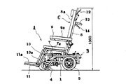
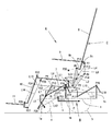
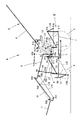
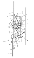
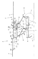
以下本考案の実施例を図面に基づいて説明する。図において、図1は本考案によるリクライニングシート式車椅子の基本姿勢を示す側面図、図2は本考案によるリクライニングシート式車椅子の後傾斜作動状態を示す側面図、図3は本考案によるリクライニングシート式車椅子の水平作動状態を示す側面図、図4は本考案によるリクライニングシート式車椅子の水平・上昇作動状態を示す側面図、図5は図1に対応する説明用フレーム構成図、図6は図2に対応する説明用フレーム構成図、図7は図3に対応する説明用フレーム構成図、図8は図4に対応する説明用フレーム構成図である。 Embodiments of the present invention will be described below with reference to the drawings. 1 is a side view showing a basic posture of a reclining seat type wheelchair according to the present invention, FIG. 2 is a side view showing a rear tilt operation state of the reclining seat type wheelchair according to the present invention, and FIG. 3 is a reclining seat type according to the present invention. 4 is a side view showing the horizontal / lifting operation state of the reclining seat type wheelchair according to the present invention, FIG. 5 is an explanatory frame configuration diagram corresponding to FIG. 1, and FIG. FIG. 7 is an explanatory frame configuration diagram corresponding to FIG. 3, and FIG. 8 is an explanatory frame configuration diagram corresponding to FIG.
図1において、Aはリクライニングシート式車椅子であり、下段フレーム1の前部(図1において左部)に前輪4を、後部(図1において右部)に後輪5を有する台車部Bと、該台車部Bに昇降可能に取り付けたリクライニングシートCとを有してなる。
In FIG. 1, A is a reclining seat type wheelchair, a front wheel 4 on the front part (left part in FIG. 1) of the
リクライニングシートCは、座フレーム7、背フレーム8、アームレスト9、レッグフレーム10、及びフットレスト11を有し、これらには、緩衝用のクッション、即ち、座7a、背受け8a、アーム受け9a、脚受け10a、及び足受け11aが取り付けられている。
The reclining seat C has a
前記座フレーム7、背フレーム8、アームレスト9、レッグフレーム10、及びフットレスト11は、リンク機構により互いに連係して作動されるようになっている。即ち、図2に示すように、背フレーム8を後方に約45度の角度で傾斜させると、座フレーム7が5度〜10度の角度で上向き傾斜して着座者の前方(図2において左方)への滑りを防止し、アームレスト9は略水平に保持されて着座者が腕部を延ばせた状態で載置できるようになっている。また、レッグフレーム10及びフットレスト11は所定量上昇されるとともに、フットレスト11は略水平に保持されて着座者の脚部を持ち上げるようになっている。
The
また、図3に示すように、前記背フレーム8を後方(図3において右方)に向けて水平に回動させると、座フレーム7、背フレーム8、アームレスト9、レッグフレーム10、及びフットレスト11が水平な面状となり、着座者(患者)をリクライニングシートC上で寝かせるようになっている。また、図4に示すように、リクライニングシートCを水平な面状にした状態で昇降機15により上昇させ、患者のベッド、ストレッチャー等への移し替えが容易に行なえるようになっている。図1において、12は背フレーム8の後面側に取り付けたリクライニングレバーであり、該リクライニングレバー12を操作することによってリクライニングシートCが起倒できるようになっている。13は背フレーム8の後面側に取り付けた介護者用のブレーキレバー14付きの走行ハンドルであり、介護者はこの走行ハンドル13、ブレーキレバー14を操作することによってリクライニングシート式車椅子Aの操縦及び停止ができるようになっている。
As shown in FIG. 3, when the
次に、前記リクライニングシート式車椅子Aのフレーム構成を図5〜図6により説明する。図5において、Bは台車部、Cはリクライニングシートである。台車部Bは、ステンレス、アルミ等の金属製のパイプ、あるいは角パイプにより長方形状の下段フレーム1を形成し、該下段フレーム1の前部にステイ1aを下方に向けて突出固定し、該ステイ1aの下部に前輪4を取り付ける。また、前記下段フレーム1にスライダー3を介してスライドフレーム2を前後摺動可能に取り付け、該スライドフレーム2に後輪5を取付ける。
Next, the frame configuration of the reclining seat type wheelchair A will be described with reference to FIGS. In FIG. 5, B is a trolley part and C is a reclining seat. The carriage portion B is formed of a rectangular
前記下段フレーム1の前後方向中間部と後端部とに前部支柱1bと後部支柱1cとを起立固定し、該前部支柱1b及び後部支柱1cの上端部にそれぞれ第15支点ピンP15(以下「支点ピン」を「支点」という)、第16支点P16を介して第9リンクアームL9、第10リンクアームL10を回動可能に連結する。前記第9、第10リンクアームL9、L10は共に同一形状のL型に屈曲させ、これらを下向きにかつ長片を前部方向に向け、それぞれの屈曲部を前記前部支柱1bの第15支点P15と後部支柱1cの第16支点P16とに回動可能に連結し、各第9、第10リンクアームL9、L10の短片の下端部同士を、第11リンクアームL11により第18支点P18、第19支点P19を介して回動可能に連結する。これにより、前記第15支点P15、第16支点P16、第18支点P18、第19支点P19で略平行リンク支点を構成する。
Front struts 1b and
前記下段フレーム1の上方に取付けフレーム6を配置してその前端部と後端部とを第8支点P8、第17支点P17を介して前記第9、第10リンクアームL9、L10の長片側の前端部に回動可能に連結する。また、下段フレーム1の前部に油圧シリンダからなる昇降機15を取り付け、該昇降機15の作動ロッドを前記第9リンクアームL9の長片側(前部側)に連結する。これにより、昇降機15を伸縮作動させて第9、第10リンクアームL9、L10を上下方向に揺動させた際に、前記取付けフレーム6が第8支点P8、第17支点P17を介して水平を保持した状態で下段フレーム1に対し、垂直方向に上下動するようにする。
The mounting
前記取り付けフレーム6にリクライニングシートCを取り付ける。該リクライニングシートCは以下の如くなっている。即ち、取り付けフレーム6の前後方向中間部に第1支柱とこれよりも長い第2支柱とを前後に間隔をおいて起立固定し、各第1、第2支柱の上端部に第1支点P1及び第2支点P2を設ける。また、前記背フレーム8の下端部を前方に屈曲させて背受け8aの下がり止め片8bを形成し、該下がり止め片8bに第6支点P6を、背フレーム8の背面下部にブラケット8cを後方に向けて突出固定し、該ブラケット8cに第7支点P7を設ける。
A reclining seat C is attached to the
前記第1支点P1に第1リンクアームL1を、前記第2支点P2に三角形状の第2リンクアームL2をそれぞれ後方に向けて回動可能に連結し、前記第6支点P6に三角形状の第3リンクアームL3を、前記第7支点P7に第4リンクアームL4をそれぞれ下方に向けて回動可能に連結する。また、前記第1リンクアームL1の後部と第2リンクアームL2の前後方向中間部とに第3支点P3と第4支点P4とを設ける。該第3支点P3及び第4支点P4は、前記第1支点P1と第2支点P2とを結ぶ線と平行する線上であってかつ第1支点P1と第2支点P2と等間隔をなす位置とする。これにより、前記第1支点P1、第2支点P2、第3支点P3、第4支点P4で第1の略平行リンク支点を形成する。 A first link arm L1 is connected to the first fulcrum P1, a triangular second link arm L2 is connected to the second fulcrum P2 so as to be pivotable rearward, and a triangular first link arm L2 is connected to the sixth fulcrum P6. The three link arms L3 are connected to the seventh fulcrum P7 so that the fourth link arms L4 can turn downward. Further, a third fulcrum P3 and a fourth fulcrum P4 are provided at the rear part of the first link arm L1 and the intermediate part in the front-rear direction of the second link arm L2. The third fulcrum P3 and the fourth fulcrum P4 are on a line parallel to a line connecting the first fulcrum P1 and the second fulcrum P2, and at equal intervals between the first fulcrum P1 and the second fulcrum P2. To do. Thus, a first substantially parallel link fulcrum is formed by the first fulcrum P1, the second fulcrum P2, the third fulcrum P3, and the fourth fulcrum P4.
また、前記第3支点P3と第4支点P4とを前記第3リンクアームL3の下部2カ所に回動可能に連結し、前記第2リンクアームL2の後端部に第5支点P5を設ける。該第5支点P5は、第6支点P6と第7支点P7とを結ぶ線と平行する第4支点P4を通る線上であってかつ第6支点P6と第7支点P7と等間隔をなす位置とする。これにより、前記第4支点P4、第5支点P5、第6支点P6、第7支点P7で第2の略平行リンク支点を形成する。 Further, the third fulcrum P3 and the fourth fulcrum P4 are rotatably connected to two lower portions of the third link arm L3, and a fifth fulcrum P5 is provided at the rear end of the second link arm L2. The fifth fulcrum P5 is located on a line passing through the fourth fulcrum P4 parallel to the line connecting the sixth fulcrum P6 and the seventh fulcrum P7 and at equal intervals between the sixth fulcrum P6 and the seventh fulcrum P7. To do. As a result, a second substantially parallel link fulcrum is formed by the fourth fulcrum P4, the fifth fulcrum P5, the sixth fulcrum P6, and the seventh fulcrum P7.
これにより、第2リンクアームL2が第2支点P2を中心として下方に回動されると、第3リンクアームL3が第3支点P3及び第4支点P4を介して後下方に回動され、座フレーム7が、第3リンクアームL3に連結される第6支点P6と、第2リンクアームL2を介して第4リンクアームL4に連結される第7支点P7とによって下方に回動されつつ、後方に回動される。
As a result, when the second link arm L2 is pivoted downward about the second fulcrum P2, the third link arm L3 is pivoted rearward and downward via the third fulcrum P3 and the fourth fulcrum P4. While the
この場合、前記第2リンクアームL2が第2支点P2を中心として下方に回動されると、第1支点〜第4支点P1,P2,P3,P4が第1の略平行リンク支点となっており、また、前記第4支点〜第7支点P4,P5,P6,P7は前記第1の略平行リンク支点の一部を共有する第2の略平行リンク支点となっているため、前記背フレーム8は、第2支点P2、第4支点P4、第6支点P6を共有する座フレーム7の後部上方の仮想支点P30を中心として後傾斜しつつ下方に回動されることになる。
In this case, when the second link arm L2 is rotated downward about the second fulcrum P2, the first to fourth fulcrums P1, P2, P3, P4 become the first substantially parallel link fulcrum. In addition, since the fourth fulcrum to the seventh fulcrum P4, P5, P6, and P7 are the second substantially parallel link fulcrum sharing a part of the first substantially parallel link fulcrum, the
これにより、第1、第2、第3リンクアームL1,L2,L3の長さ及び各支点を選択することにより、これらを座フレーム7及び背フレーム8の外側(後方)に配置しながら、背フレーム8を着座者の腰部を中心として起倒させることができ、該背フレームの回動による着座者とのずれを防止することができる。また、座フレーム7に上方への突起物がなくなり、患者(着座者)の移し替が容易となる。
Accordingly, by selecting the lengths of the first, second, and third link arms L1, L2, and L3 and the respective fulcrums, these are arranged on the outside (rear) of the
前記取り付けフレーム6の前端部に第8支点P8を設け、該第8支点P8に第5リンクアームL5を上方に向けて回動可能に連結し、前記座フレーム7であってかつ第2支点P2よりも前方側に第9支点P9を設け、該第9支点P9に第6リンクアームL6を上方に向けて回動可能に連結する。そして、座フレーム7の水平状態において前記第5リンクアームL5及び第6リンクアームL6を後方に回動させて両者を第10支点P10により互いに回動可能に連結する。
An eighth fulcrum P8 is provided at the front end of the mounting
また、座フレーム7の下方に第7リンクアームL7を座フレーム7と略平行に配置し、該第7リンクアームL7の前部を前記第10支点P10に、その後端を第2リンクアームL2の下部に設けた第11支点P11にそれぞれ回動可能に連結する。前記第11支点P11は、第6リンクアームL6と略平行する第2支点P2の交差線上であってかつ第9支点P9と第10支点P10と略等間隔の位置とし、これにより、第2支点P2、第9支点P9、第10支点P10、第11支点P11を第3の略平行リンク支点とする。
Further, a seventh link arm L7 is arranged below the
これにより、前記第2リンクアームL2が下方に回動されると、第11支点P11、第7リンクアームL7を介して第10支点P10が前方に移動され、第5リンクアームL5は第8支点P8を中心として、また、第6リンクアームL6は第9支点P9を中心として前方に回動されることになる。前記第8支点P8は取り付けフレーム6に位置決め(固定)されているので、前記第5リンクアームL5と第6リンクアームL6が後ろ向き屈曲から一直線に至る間は、座フレーム7が第2支点P2を中心として水平状態から上向きに回動され(図6)、前記第5リンクアームL5と第6リンクアームL6が一直線から前向き屈曲に至る間は、座フレーム7は第2支点P2を中心として下方き、つまり水平方向に復帰回動されることになる(図7)。
Accordingly, when the second link arm L2 is rotated downward, the tenth fulcrum P10 is moved forward via the eleventh fulcrum P11 and the seventh link arm L7, and the fifth link arm L5 is moved to the eighth fulcrum. The sixth link arm L6 is pivoted forward around the ninth fulcrum P9, with P8 as the center. Since the eighth fulcrum P8 is positioned (fixed) on the
本例では、図6に示すように、背フレーム8が後方に向かって約45度傾斜されるまでは、座フレーム7が次第に上向き傾斜(最大12度)し、また、図7に示すように、背フレーム8の後傾斜角約45度を越えると座フレーム7が次第に水平方向に復帰回動し、背フレーム8が水平状態になると、座フレーム7も水平になるようにする。これにより、着座者が後傾斜した際に座7a上で前方に滑らなくなり、また、背フレーム8を水平に回動させた際には、座フレーム7が水平状態となって着座者はリクライニングシートC上で寝る(仮眠)できることになる。
In this example, as shown in FIG. 6, until the
前記背フレーム8の上下方向中間部に第12支点P12を設け、該第12支点P12にアームレスト9を前方に延出させて上下回動可能に連結し、前記アームレスト9の第12支点P12よりも後部側に第13支点P13を設け、該第13支点P13に第8リンクアームL8を回動可能に連結し、該第8リンクアームL8の下端を第3リンクアームL3の第4支点P4と第6支点P6との間に設けた第14支点P14に回動可能に連結する。
A twelfth fulcrum P12 is provided at an intermediate portion in the vertical direction of the
これにより、背フレーム8が後方に回動された際に、第8リンクアームL8が第12支点P12に対する第13支点P13の降下量を所定の比率で減少させ、アームレスト9を常時略水平状態に保持するようにし、図7に示すように、背フレーム8を水平状に回動させた際に、座フレーム7、背フレーム8及びアームレスト9を水平な面状にして患者(着座者)の移し替を容易にする。
Thus, when the
前記座フレーム7の前端部にレッグフレーム10を第22支点P22を介して回動可能に連結するとともに、該レッグフレーム10を下方に向けて回動させ、前述した第7リンクアームL7を第10支点P10から前方に突出させるとともに、該突出端部に第23支点P23を設け、該第23支点P23に第13リンクアームL13を回動可能に連結し、該第13リンクアームL13を前方に回動させ、その前端部を前記レッグフレーム10の上下方向中間部に設けた第24支点P24に回動可能に連結する。
The
前記レッグフレーム10下端部にフットレスト11を第25支点P25を介して回動可能に連結するとともに、該フットレスト11を前方に向けて回動させ、該フットレスト11の後端部に、前記第25支点P25に対して下方かつ後方に位置する第27支点P27を設ける。また、前記該レッグフレーム10の後方に、第22支点P22と第25支点P25とを結ぶ線と平行する第14リンクアームL14を配置し、該第14リンクアームL14の下端を前記第27支点P27に、上端を座フレーム7の前部に第26支点P26を介して回動可能に連結する。前記第26支点P26と第27支点P27との間隔は第22支点P22と第25支点P25との間隔と等しくし、これにより、第22支点P22、第25支点P25、第26支点P26、第27支点P27を第4の略平行リンク支点とする。
The
これにより、前記レッグフレーム10及びフットレスト11は以下のように動作する。即ち、背フレーム8を後方に回動させると、第2リンクアームL2、第7リンクアームL7、第13リンクアームL13を介してレッグフレーム10が第22支点P22を中心として上方に回動される。また、レッグフレーム10が上方に回動されると、第25支点P25を介してフットレスト11が上昇される。
Accordingly, the
この場合、レッグフレーム10は、第3の略平行リンク支点、即ち、第2支点P2、第9支点P9、第10支点P10、第11支点P11を介して前後動される第7リンクアームL7、及び該第7リンクアームL7に連結された第13リンクアームL13によって回動されるため、前記レッグフレーム10は背フレーム8と連動して略同方向に回動されることになる。また、フットレスト11は、第4の略平行リンク支点、即ち、第22支点P22、第25支点P25、第26支点P26、第27支点P27を介して回動されるため、レッグフレーム10の回動に左右されることなく、略水平状態に保持されることになる。
In this case, the
このため、背フレーム8の起立時、及び後方への傾斜時には図5、図6に示すように、フットレスト11が患者(着座者)の足部を受け、該患者の疲労を軽減することになる。また、図7に示すように、背フレーム8が水平状態になった際には、座フレーム7、背フレーム8、レッグフレーム10、及びフットレスト11が水平な面状となり、この状態で昇降機15を伸長動させると、図8に示すように、リクライニングシートCが水平状態で上昇され、患者をリクライニングシート式車椅子Aとベッド、ストレッチャー、あるいは自動車との間の移し替えが安全に行なえることになる。
Therefore, when the
また、リクライニングシートCは、椅子型、後傾斜、あるいは水平に調節された姿勢を保持して昇降できるので、着座者は任意の姿勢で視点の上下位置、あるいは手の届く位置を調節することができる。 In addition, the reclining seat C can move up and down while maintaining a chair-type, rear-tilt, or horizontally adjusted posture, so that the seated person can adjust the vertical position of the viewpoint or the reachable position in any posture. it can.
A リクライニングシート式車椅子
B 台車部
C リクライニングシート
1 下段フレーム
2 スライドフレーム
3 スライダー
4 前輪
5 後輪
6 取り付けフレーム
7 座フレーム
7a 座
8 背フレーム
8a 背受け
9 アームレスト
9a アーム受け
10 レッグフレーム
10a 脚受け
11 フットフレーム
11a 足受け
12 リクライニングレバー
13 走行ハンドル
14 ブレーキレバー
15 昇降機
P1〜P27 第1支点〜第27支点
P30 仮想支点
L1〜L14 第1リンクアーム〜第14リンクアーム
A Reclining seat type wheelchair B Bogie part
Claims (8)
Priority Applications (1)
| Application Number | Priority Date | Filing Date | Title |
|---|---|---|---|
| JP2007009171U JP3139367U (en) | 2007-11-28 | 2007-11-28 | Reclining seat and reclining seat type wheelchair |
Applications Claiming Priority (1)
| Application Number | Priority Date | Filing Date | Title |
|---|---|---|---|
| JP2007009171U JP3139367U (en) | 2007-11-28 | 2007-11-28 | Reclining seat and reclining seat type wheelchair |
Publications (1)
| Publication Number | Publication Date |
|---|---|
| JP3139367U true JP3139367U (en) | 2008-02-14 |
Family
ID=43289591
Family Applications (1)
| Application Number | Title | Priority Date | Filing Date |
|---|---|---|---|
| JP2007009171U Expired - Lifetime JP3139367U (en) | 2007-11-28 | 2007-11-28 | Reclining seat and reclining seat type wheelchair |
Country Status (1)
| Country | Link |
|---|---|
| JP (1) | JP3139367U (en) |
Cited By (3)
| Publication number | Priority date | Publication date | Assignee | Title |
|---|---|---|---|---|
| JP2015027321A (en) * | 2013-07-30 | 2015-02-12 | 株式会社カワムラサイクル | Wheelchair |
| WO2015040846A1 (en) * | 2013-09-17 | 2015-03-26 | パナソニックIpマネジメント株式会社 | Wheelchair and combination bed |
| JP2019025064A (en) * | 2017-07-31 | 2019-02-21 | ユキ技研株式会社 | Reclining seat and wheelchair with reclining seat |
-
2007
- 2007-11-28 JP JP2007009171U patent/JP3139367U/en not_active Expired - Lifetime
Cited By (3)
| Publication number | Priority date | Publication date | Assignee | Title |
|---|---|---|---|---|
| JP2015027321A (en) * | 2013-07-30 | 2015-02-12 | 株式会社カワムラサイクル | Wheelchair |
| WO2015040846A1 (en) * | 2013-09-17 | 2015-03-26 | パナソニックIpマネジメント株式会社 | Wheelchair and combination bed |
| JP2019025064A (en) * | 2017-07-31 | 2019-02-21 | ユキ技研株式会社 | Reclining seat and wheelchair with reclining seat |
Similar Documents
| Publication | Publication Date | Title |
|---|---|---|
| JP5340480B2 (en) | bed | |
| JPH05103818A (en) | Human engineering body supporting device | |
| JP3547415B2 (en) | Reclining wheelchair | |
| WO2021116871A1 (en) | Vehicle with transforming seat | |
| JP5370900B2 (en) | Reclining wheelchair | |
| JP3139367U (en) | Reclining seat and reclining seat type wheelchair | |
| JP5666670B2 (en) | Chair with auxiliary mechanism | |
| JP2017148194A (en) | Transfer support device | |
| EP3219299B1 (en) | Wheelchair | |
| JP3680160B2 (en) | wheelchair | |
| JP4508760B2 (en) | Standing auxiliary chair | |
| JP4187204B2 (en) | Attitude control type electric wheelchair | |
| JP6349352B2 (en) | Reclining wheelchair | |
| JP5433312B2 (en) | Lifting reclining wheelchair | |
| JP3755822B2 (en) | Nursing wheelchair | |
| JP6971648B2 (en) | Transfer support device | |
| JP2010022589A (en) | Standing assist apparatus | |
| JP5896464B2 (en) | Self-operated wheelchair | |
| JP2007075427A (en) | Reclining seat | |
| JP3934758B2 (en) | Wheelchair with lifting device | |
| JPH10234781A (en) | Moving bed and chair device | |
| JP2004290275A (en) | Wheelchair | |
| JPH11113967A (en) | Wheelchair | |
| JP3195211U (en) | Lifting wheelchair | |
| JP7178840B2 (en) | Interlocking mechanism between seat and back, and stretcher |
Legal Events
| Date | Code | Title | Description |
|---|---|---|---|
| R150 | Certificate of patent or registration of utility model |
Free format text: JAPANESE INTERMEDIATE CODE: R150 |
|
| FPAY | Renewal fee payment (event date is renewal date of database) |
Free format text: PAYMENT UNTIL: 20110123 Year of fee payment: 3 |
|
| FPAY | Renewal fee payment (event date is renewal date of database) |
Free format text: PAYMENT UNTIL: 20140123 Year of fee payment: 6 |
|
| R250 | Receipt of annual fees |
Free format text: JAPANESE INTERMEDIATE CODE: R250 |
|
| R250 | Receipt of annual fees |
Free format text: JAPANESE INTERMEDIATE CODE: R250 |
|
| R250 | Receipt of annual fees |
Free format text: JAPANESE INTERMEDIATE CODE: R250 |
|
| EXPY | Cancellation because of completion of term |