JP2021181985A - Test liquid product - Google Patents

Test liquid product Download PDF

Info

Publication number
JP2021181985A
JP2021181985A JP2021080787A JP2021080787A JP2021181985A JP 2021181985 A JP2021181985 A JP 2021181985A JP 2021080787 A JP2021080787 A JP 2021080787A JP 2021080787 A JP2021080787 A JP 2021080787A JP 2021181985 A JP2021181985 A JP 2021181985A
Authority
JP
Japan
Prior art keywords
film
test
test solution
test liquid
container body
Prior art date
Legal status (The legal status is an assumption and is not a legal conclusion. Google has not performed a legal analysis and makes no representation as to the accuracy of the status listed.)
Pending
Application number
JP2021080787A
Other languages
Japanese (ja)
Inventor
勇禧 對馬
Yuki Tsushima
Current Assignee (The listed assignees may be inaccurate. Google has not performed a legal analysis and makes no representation or warranty as to the accuracy of the list.)
ASAKUSA JOZAI KENKYUSHO KK
Original Assignee
ASAKUSA JOZAI KENKYUSHO KK
Priority date (The priority date is an assumption and is not a legal conclusion. Google has not performed a legal analysis and makes no representation as to the accuracy of the date listed.)
Filing date
Publication date
Application filed by ASAKUSA JOZAI KENKYUSHO KK filed Critical ASAKUSA JOZAI KENKYUSHO KK
Publication of JP2021181985A publication Critical patent/JP2021181985A/en
Pending legal-status Critical Current

Links

Images

Landscapes

  • Packages (AREA)
  • Wrappers (AREA)

Abstract

To provide a test liquid product which is obtained by deairing in advance a test liquid to be used in an elution test, before filling it into a hermetic container, and further, to provide a test liquid product using a container which prevents elution of organic solvent components and antioxidant components and the like.SOLUTION: A test liquid product 1 particularly eliminates work and time required for performing complicated deairing work by a test operator, since a test liquid 2 subjected to deairing in beforehand is filled therein. Further, in a container body 3 suitable for the test liquid product 1, a sealant film of a laminate film constituting the container body 3 is composed of additive-free polyolefin, and furthermore, lamination is performed at least from the sealant film to a barrier film directly without using none of an adhesive material containing an organic solvent or an anchor coating agent, or via a solventless adhesive layer not containing an organic solvent. Thus, a component such as an organic solvent is prevented from eluting to a content side, and adverse effects caused by an eluate on the content can be inhibited.SELECTED DRAWING: Figure 5

Description

本発明は、固形製剤の溶出試験又は崩壊試験に使用する試験液を収容した試験液製品に関する。 The present invention relates to a test solution product containing a test solution used for a dissolution test or a disintegration test of a solid preparation.

錠剤、カプセル剤、顆粒剤等の内服用医薬品固形製剤においては、有効成分が同一同量であっても、服用後の有効成分の溶出速度が異なると、臨床効果に差が生じる場合がある。このため溶出試験は、医薬品製造の際の重要な品質管理項目の一つとして位置づけられており、日本薬局方、米国薬局方、欧州薬局方三極での調和合意に基づいて規定された試験の一つでもある。たとえば第十七改正日本薬局方(17局)において溶出試験法は、「本試験は、経口製剤について溶出試験規格に適合しているかどうかを判定するために行うものであるが、併せて著しい生物学的非同等を防ぐことを目的としている」と規定され、使用する装置、操作法、判定法等を詳細に規定している。また、溶出試験装置については、その寸法が規定された許容誤差の中にあることの確認や、試験中に監視が必要な重要なパラメータとして試験液の温度や試験液の容量、パドルやバスケットの回転速度などを、定期的に点検することが求められている。また、試験液については、試験液量は規定された容量の±1%以内とし、試験液の温度は37℃±0.5℃以内に保持し、試験液が緩衝液の場合pHを規定値の±0.05以内となるように調整することとしている。 In solid pharmaceutical formulations for internal use such as tablets, capsules, and granules, even if the amount of the active ingredient is the same, if the dissolution rate of the active ingredient after administration is different, the clinical effect may differ. For this reason, the dissolution test is positioned as one of the important quality control items in the manufacture of pharmaceutical products, and the test is defined based on the harmonized agreement between the Japanese Pharmacopoeia, the United States Pharmacopeia, and the European Pharmacopoeia. There is also one. For example, in the 17th revised Japanese Pharmacopoeia (17th Bureau), the dissolution test method states, "This test is conducted to determine whether or not the oral preparation conforms to the dissolution test standard, but it is also a remarkable organism. The purpose is to prevent scientific inequality. "It stipulates in detail the equipment, operation method, judgment method, etc. to be used. For dissolution test equipment, confirm that the dimensions are within the specified tolerance, and the important parameters that need to be monitored during the test are the temperature of the test solution, the volume of the test solution, and the paddle and basket. It is required to regularly check the rotation speed and the like. For the test solution, the amount of the test solution should be within ± 1% of the specified volume, the temperature of the test solution should be kept within 37 ° C ± 0.5 ° C, and if the test solution is a buffer solution, the pH should be the specified value. It is decided to adjust so that it is within ± 0.05 of.

また、試験液としては、pHが1.2の溶出試験第一液、およびpHが6.8の溶出試験第二液、水、そして各種緩衝液が用いられる。尚、例えば固形製剤の製造時、品質管理においては、各製剤毎に定められた試験液の種類、試験液量、試験条件の下、少なくとも各バッチ6個の試料について同時に試験が行われ、その製剤が溶出試験規格に適合しているかどうかの判定がなされる。 As the test solution, an elution test first solution having a pH of 1.2, an elution test second solution having a pH of 6.8, water, and various buffer solutions are used. For example, in the production of solid formulations and in quality control, at least 6 samples in each batch are simultaneously tested under the test solution type, test solution amount, and test conditions specified for each formulation. It is determined whether the pharmaceutical product conforms to the dissolution test standard.

従来、溶出試験の試験液は、日本薬局方に基づいて試験実施者が用事調製するか、一定量を作り置きして使用していたが、これが試験実施者にとって大きな負担となっていた。例えば、回転バスケット法やパドル法により溶出試験を行う場合、試験開始前に、試験実施者が試薬や水を秤量して溶解混合し、pHを調整して必要な試験液(少なくとも6個の試料の試験を行うために、規定された1回分の試験液量の6倍以上。通常1回の試験には900mLが使用されるため、900mL×6、すなわち5400mLの試験液が必要となる)を調製し、さらに、そのなかから規定された試験液量を正確に(±1%以内)計り取り、規定の容器に入れ、規定の温度(通常37℃)まで加温してようやく試験を開始できる。したがって試験開始までに多大な時間と労力が必要となる。 Conventionally, the test solution for the dissolution test has been prepared by the tester based on the Japanese Pharmacopoeia or prepared in a fixed amount and used, but this has been a heavy burden on the tester. For example, when the dissolution test is performed by the rotary basket method or the paddle method, the tester weighs the reagents and water, dissolves and mixes them, adjusts the pH, and adjusts the pH before starting the test (at least 6 samples). 6 times or more of the specified amount of test solution for one test. Normally, 900 mL is used for one test, so 900 mL x 6, that is, 5400 mL of test solution is required). After preparation, the specified amount of test solution can be accurately measured (within ± 1%), placed in the specified container, heated to the specified temperature (usually 37 ° C), and finally the test can be started. .. Therefore, a great deal of time and effort is required before the start of the test.

尚、試験実施者による試験液の調製は基本的に大気下で行うため、試験液中には調製時の室温に平衡した空気が溶解している。尚、通常気体の溶解度は温度が上がると小さくなることが知られている。そのため試験温度である37℃迄加温すると、調製時試験液中に溶解していた空気は徐々に大気中に揮散する。しかしながらこの揮散速度は緩慢であるため、37℃になっても試験液中にはなおも過飽和状態の空気が残存し、試験開始後、これが試験中に気泡となって発生し溶出結果に悪影響を与える可能性がある。 Since the test solution is basically prepared by the tester in the atmosphere, air equilibrated at room temperature at the time of preparation is dissolved in the test solution. It is known that the solubility of a gas usually decreases as the temperature rises. Therefore, when heated to the test temperature of 37 ° C., the air dissolved in the test solution at the time of preparation gradually volatilizes into the atmosphere. However, since this volatilization rate is slow, supersaturated air still remains in the test solution even at 37 ° C, and after the start of the test, this is generated as bubbles during the test and adversely affects the elution result. May give.

ここで、第十七改正日本薬局方の注意事項として「試験液に溶存している気体は気泡の原因となることがあり、試験結果に影響を与えることがある。溶存している気体が溶出試験結果に影響を及ぼす場合には、試験の前に脱気する。」と明記され、脱気法の例が記載されている。例えば第17改正日本薬局方では、「試験液をかき混ぜながら41℃に加温し、直ちに吸引下かき混ぜながら孔径0.45μm以下のフィルターを用いてろ過し、更に、5分間減圧下でかき混ぜる。他のバリデーションされた脱気方法を用いてもよい。」と規定している。この脱気方法も試験液の加温や減圧ろ過を必要とする手間のかかる操作である。 Here, as a note of the 17th revision of the Japanese Pharmacopoeia, "The gas dissolved in the test solution may cause bubbles and may affect the test results. The dissolved gas elutes. If it affects the test results, degas before the test. " For example, in the 17th revised Japanese Pharmacopoeia, "The test solution is heated to 41 ° C while stirring, immediately filtered using a filter having a pore size of 0.45 μm or less while stirring under suction, and further stirred under reduced pressure for 5 minutes. You may use the validated degassing method of. " This degassing method is also a time-consuming operation that requires heating of the test solution and vacuum filtration.

したがって、上述のように脱気試験液の使用が規定されている製剤について溶出試験を行う場合には、試験開始直前に、使用する試験液を所定の脱気度まで脱気する脱気作業が必要となる。そして脱気された試験液は直ちに試験容器の中に移し入れられ、すみやかに規定温度である37℃まで加温されたのち初めて試験が開始される。尚、脱気作業の負担軽減のために非特許文献1、2のように種々の装置が上市されているが、装置の購入費の負担や装置のメンテナンスなどが必要であるうえ、前述のように別途試験液を調製する必要があること、調製した試験液を装置への移し替える手間などがかかること、脱気装置から脱気された試験液を小分けする作業が伴うなど、試験実施者の負担軽減には不十分である。 Therefore, when the dissolution test is performed on the pharmaceutical product for which the use of the degassing test solution is specified as described above, the degassing operation for degassing the test solution to be used to a predetermined degassing degree is performed immediately before the start of the test. You will need it. Then, the degassed test solution is immediately transferred into the test container and promptly heated to the specified temperature of 37 ° C. before the test is started. Although various devices have been put on the market as in Non-Patent Documents 1 and 2 in order to reduce the burden of degassing work, it is necessary to bear the purchase cost of the device and to maintain the device, as described above. It is necessary to prepare a test solution separately, it takes time to transfer the prepared test solution to the device, and it involves the work of subdividing the test solution degassed from the degassing device. It is not enough to reduce the burden.

一方、事前に作り置きした試験液は、通常開閉可能な蓋つきで小分け取り出しが可能な容器に入れて、水分の蒸発やpHの変化、微生物の繁殖が生じないように保管する必要がある。また、脱気した試験液を作り置きする場合には、空気を再吸収しないような気密容器に入れ、試験に必要な脱気状態を保つ必要がある。 On the other hand, it is necessary to put the test solution prepared in advance in a container that can be taken out in small portions with a lid that can be opened and closed, and store it so that evaporation of water, change in pH, and propagation of microorganisms do not occur. In addition, when preparing and storing the degassed test solution, it is necessary to put it in an airtight container that does not reabsorb air and maintain the degassed state required for the test.

尚、固形製剤の開発及び製造においては、製剤が試験液中、定められた規定時間内に崩壊するかどうかを確認する崩壊試験も行われる。この崩壊試験に用いられる試験液には脱気作業は必ずしも必要ではないが、その他の作業については溶出試験と同様であり、試験実施者の負担が大きい。 In the development and manufacture of the solid product, a disintegration test is also performed to confirm whether the product disintegrates in the test solution within a specified specified time. The test solution used for this disintegration test does not necessarily require degassing work, but the other work is the same as the dissolution test, which imposes a heavy burden on the tester.

このように溶出試験、崩壊試験の実施には、試験開始までに試験実施者に多大な時間と労力が必要とされ、特に脱気が必要な場合にはその労力はさらに増大する。 As described above, carrying out the dissolution test and the disintegration test requires a great deal of time and labor for the tester before the start of the test, and the labor is further increased especially when degassing is required.

ただし、現在では例えば非特許文献3、4に示されるように、溶出試験又は崩壊試験に使用される試験液やその濃縮液を容器に充填した製品が市販されるようになっており、試験液をそのまま、または濃縮液を水で希釈して使用するなど、試験実施者が調製する場合に比べて試験実施者の負担が軽減される傾向にある。 However, as shown in Non-Patent Documents 3 and 4, for example, a test solution used for a dissolution test or a disintegration test and a product in which a concentrated solution thereof is filled in a container are now on the market. The burden on the tester tends to be reduced as compared with the case where the tester prepares the mixture as it is or by diluting the concentrate with water.

これら試験液の容器の形状としては、硬質PEボトル、減容ポリ容器、キューピーコンテナー等が一般的であり、また容器のサイズとしては内用液が試験液の場合は3L〜20L、内用液が濃縮液である場合には3L〜10Lのサイズのものが上市されている。また、下記[特許文献1]には、固形製剤の溶出試験又は崩壊試験に使用される試験液が容器に充填された試験液製品に関する発明が開示されている。 The shape of the container for these test solutions is generally a hard PE bottle, a volume-reducing plastic container, a Kewpie container, etc., and the size of the container is 3 L to 20 L when the internal solution is a test solution. When is a concentrate, 3L to 10L sizes are on the market. Further, the following [Patent Document 1] discloses an invention relating to a test liquid product in which a test liquid used for a dissolution test or a disintegration test of a solid preparation is filled in a container.

この[特許文献1]に記載された試験液製品に用いられる容器は、金属酸化物蒸着フィルムと、最内層に配置されたシ一ラントフィルムとを含む積層フィルムから構成され、金属酸化物蒸着フィルムとシーラントフィルムとを積層するにあたり、接着剤を使用して金属酸化物蒸着フィルムとシーラントフィルムとの層間剥離強度を高めている。そして、接着剤としては、イソシアネート系化合物、ポリエチレンイミン、変性ポリブタジエン、有機チタネート系化合物等の化合物をメタノール、酢酸エチル等の有機溶剤に溶解したものが用いられる。また、シーラントフィルムとして用いられるポリオレフィンフィルムには、通常、ブチルヒドロキシアニソール(BHA)又はジブチルヒドロキシトルエン(BHT)等の酸化防止剤が添加されている。尚、BHA及びBHTは、医薬品添加剤及び食品添加物として長年にわたって使用されている化合物であり、人体に対する安全性は高いと考えられる。 The container used for the test liquid product described in [Patent Document 1] is composed of a laminated film containing a metal oxide vapor-deposited film and a serialant film arranged in the innermost layer, and is composed of a metal oxide-deposited film. When laminating the sealant film and the sealant film, an adhesive is used to increase the delamination strength between the metal oxide vapor-deposited film and the sealant film. As the adhesive, a compound obtained by dissolving a compound such as an isocyanate compound, polyethyleneimine, modified polybutadiene, or an organic titanate compound in an organic solvent such as methanol or ethyl acetate is used. Further, an antioxidant such as butylhydroxyanisole (BHA) or dibutylhydroxytoluene (BHT) is usually added to the polyolefin film used as the sealant film. BHA and BHT are compounds that have been used as pharmaceutical additives and food additives for many years, and are considered to be highly safe for the human body.

特開2014−70964号公報Japanese Unexamined Patent Publication No. 2014-70964 “脱気分注装置『EMD−21P』”、〔online〕、株式会社樋口商会、〔令和2年8月27日検索〕、インターネット<URL:https://www.higuchi-inc.co.jp/business-products/pharmaceuticals/analysis/"De-mood injection device" EMD-21P "", [online], Higuchi Shokai Co., Ltd., [Search on August 27, 2nd year of Reiwa], Internet <URL: https://www.higuchi-inc.co.jp / business-products / pharmaceuticals / analysis / “溶出試験液加熱脱気タンク HDR−250”〔online〕、富山産業株式会社、〔令和2年8月27日検索〕、インターネット<URL: https://www.toyamas.co.jp/products/dissolution/"Elution test solution heating degassing tank HDR-250" [online], Toyama Sangyo Co., Ltd., [Search on August 27, 2nd year of Reiwa], Internet <URL: https://www.toyamas.co.jp/products / dissolution / “製剤安定性試験用試薬”、〔online〕、関東化学株式会社、〔令和2年3月16日検索〕、インターネット<URL:https://products.kanto.co.jp/web/index.cgi?c=t_product_table&pk=413&_ga=2.259041225.210980883.1584262288-1651687052.1582866595>"Reagent for formulation stability test", [online], Kanto Chemical Co., Inc., [Searched on March 16, 2nd year of Reiwa], Internet <URL: https://products.kanto.co.jp/web/index. cgi? c = t_product_table & pk = 413 & _ga = 2.259041225.210980883.1584262288-1651687052.1582866595> “崩壊試験・溶出試験用試薬”、〔online〕、富士フィルム和光純薬株式会社、〔令和2年3月16日検索〕、インターネット<URL:https://labchem-wako.fujifilm.com/jp/category/00636.html"Reagent for disintegration test / dissolution test", [online], Fujifilm Wako Pure Chemical Industries, Ltd., [Searched on March 16, 2nd year of Reiwa], Internet <URL: https://labchem-wako.fujifilm.com/ jp / category / 00636.html

ここで、[特許文献1]に記載の発明を含めこれらの試験液製品は単に、調製済の試験液やその濃縮液を容器に充填し密栓したものであり、脱気は行われていない。よって、脱気が必要な溶出試験を実施する場合には、試験実施者は試験開始直前にこれらの試験液の脱気を行う必要がある。 Here, these test liquid products including the invention described in [Patent Document 1] are simply filled with a prepared test liquid or a concentrated liquid thereof in a container and sealed tightly, and are not degassed. Therefore, when conducting a dissolution test that requires degassing, the tester needs to degas these test solutions immediately before the start of the test.

また、溶出試験は溶出試験液中に医薬品製剤から有効成分が溶け出す速度を測定する試験であり、通常、試験液中の有効成分の定量法として、紫外線吸収測定法や、高速液体クロマトグラフィー(HPLC)法等が用いられる。HPLC法では、検出器として紫外吸光度検出器が用いられる場合が多い。そのため、溶出試験液は紫外線吸収を持たないことが望ましい。 In addition, the dissolution test is a test to measure the rate at which the active ingredient dissolves from the pharmaceutical preparation in the dissolution test solution. Usually, as a method for quantifying the active ingredient in the test solution, an ultraviolet absorption measurement method or high performance liquid chromatography ( HPLC) method or the like is used. In the HPLC method, an ultraviolet absorbance detector is often used as a detector. Therefore, it is desirable that the elution test solution does not absorb ultraviolet rays.

しかしながら、例えば[特許文献1]に記載された試験液製品のように、容器を構成する積層フィルムが金属酸化物蒸着フィルムとシーラントフィルムとを積層する際に有機溶剤を含む接着剤やアンカーコート剤を使用していたり、シーラントフィルムがBHA又はBHT等の酸化防止剤を含んでいたりする場合には、接着剤やアンカーコート剤の溶剤成分やシーラントフィルムの酸化防止剤成分が試験液中に溶け出し、これら溶剤成分や酸化防止剤成分の紫外線吸収が溶出試験に悪影響を与えるおそれがある。 However, as in the case of the test solution product described in [Patent Document 1], for example, when the laminated film constituting the container is laminated with the metal oxide vapor deposition film and the sealant film, an adhesive or an anchor coating agent containing an organic solvent is used. If the sealant film contains an antioxidant such as BHA or BHT, the solvent component of the adhesive or anchor coating agent or the antioxidant component of the sealant film will dissolve in the test solution. , The absorption of ultraviolet rays of these solvent components and antioxidant components may adversely affect the dissolution test.

本発明は上記事情に鑑みてなされたものであり、溶出試験に使用する試験液を予め脱気したうえで気密容器に充填した試験液製品の提供を目的とする。また、有機溶剤成分や酸化防止剤成分等の溶出が抑制された試験液製品の提供を目的とする。 The present invention has been made in view of the above circumstances, and an object of the present invention is to provide a test liquid product in which the test liquid used for the dissolution test is degassed in advance and then filled in an airtight container. Another object of the present invention is to provide a test solution product in which elution of organic solvent components, antioxidant components, etc. is suppressed.

本発明は、
(1)固形製剤の溶出試験又は崩壊試験に使用される試験液2と、前記試験液2が充填された容器本体3と、を有する試験液製品において、前記試験液2の液中の空気の溶存量が溶存酸素濃度として0mg/L〜6mg/Lであることを特徴とする試験液製品1を提供することにより、上記課題を解決する。
(2)試験液2の溶存酸素濃度をxとし、容器本体3内のヘッドスペース30の試験液2量に対する容積比をyとしたときに、
y≦−0.0231x+0.1867x−0.6804x+2.3516
を満たすことを特徴とする上記(1)記載の試験液製品1を提供することにより、上記課題を解決する。
(3)試験液2の溶存酸素濃度が0mg/L〜4.5mg/Lで、容器本体3内のヘッドスペース30の試験液2量に対する容積比が0vol%〜1vol%であることを特徴とする上記(2)記載の試験液製品1を提供することにより、上記課題を解決する。
(4)試験液2の充填量が1回の溶出試験の規定容量の±1%の範囲内にあることを特徴とする上記(1)乃至上記(3)のいずれかに記載の試験液製品1を提供することにより、上記課題を解決する。
(5)容器本体3が、無添加ポリオレフィンからなるシーラントフィルム111と、熱可塑性樹脂からなるベースフィルム113aの一方又は両方の面に無機物バリア層113b、113cを有するバリアフィルム113と、を含み、前記シーラントフィルム111と前記バリアフィルム113とが直接積層されている積層フィルム101A〜101Cにより構成されていることを特徴とする上記(1)乃至(4)のいずれかに記載の試験液製品1を提供することにより、上記課題を解決する。
(6)容器本体3が、無添加ポリオレフィンからなるシーラントフィルム111と、熱可塑性樹脂からなるプラスチックフィルム112と、熱可塑性樹脂からなるベースフィルム113aの一方又は両方の面に無機物バリア層113b、113cを有するバリアフィルム113と、をこの順に含み、前記シーラントフィルム111と前記プラスチックフィルム112とが直接積層され、かつ、前記プラスチックフィルム112と前記バリアフィルム113とが直接積層されている積層フィルム301A〜301Cにより構成されていることを特徴とする上記(1)乃至(4)のいずれかに記載の試験液製品1を提供することにより、上記課題を解決する。
(7)容器本体3が、無添加ポリオレフィンからなるシーラントフィルム111と、熱可塑性樹脂からなるベースフィルム113aの一方又は両方の面に無機物バリア層113b、113cを有するバリアフィルム113と、を含み、前記シーラントフィルム111と前記バリアフィルム113とが有機溶剤を含まない無溶剤接着層により接着された積層フィルム101A〜101Cにより構成されていることを特徴とする上記(1)乃至(4)のいずれかに記載の試験液製品1を提供することにより、上記課題を解決する。
(8)容器本体3が、無添加ポリオレフィンからなるシーラントフィルム111と、熱可塑性樹脂からなるプラスチックフィルム112と、熱可塑性樹脂からなるベースフィルム113aの一方又は両方の面に無機物バリア層113b、113cを有するバリアフィルム113と、をこの順に含み、前記シーラントフィルム111と前記プラスチックフィルム112とが有機溶剤を含まない無溶剤接着層により接着され、かつ、前記プラスチックフィルム112と前記バリアフィルム113とが有機溶剤を含まない無溶剤接着層により接着された積層フィルム301A〜301Cにより構成されていることを特徴とする上記(1)乃至(4)のいずれかに記載の試験液製品1を提供することにより、上記課題を解決する。
(9)容器本体3が、バリアフィルム113側に、熱可塑性樹脂からなるカバーフィルム114をさらに有する積層フィルム201A〜201C、401A〜401Cにより構成されていることを特徴とする上記(5)乃至(8)のいずれかに記載の試験液製品1を提供することにより、上記課題を解決する。
The present invention
(1) In a test liquid product having a test liquid 2 used for an dissolution test or a disintegration test of a solid preparation and a container body 3 filled with the test liquid 2, the air in the liquid of the test liquid 2 The above problem is solved by providing the test liquid product 1 characterized in that the dissolved amount is 0 mg / L to 6 mg / L as the dissolved oxygen concentration.
(2) When the dissolved oxygen concentration of the test liquid 2 is x and the volume ratio of the head space 30 in the container body 3 to the amount of the test liquid 2 is y.
y ≦ -0.0231x 3 + 0.1867x 2 -0.6804x + 2.3516
The above problem is solved by providing the test liquid product 1 according to the above (1), which is characterized by satisfying the above conditions.
(3) The characteristic is that the dissolved oxygen concentration of the test liquid 2 is 0 mg / L to 4.5 mg / L, and the volume ratio of the head space 30 in the container body 3 to the amount of the test liquid 2 is 0 vol% to 1 vol%. The above problem is solved by providing the test solution product 1 according to the above (2).
(4) The test liquid product according to any one of the above (1) to (3), wherein the filling amount of the test liquid 2 is within the range of ± 1% of the specified capacity of one dissolution test. The above problem is solved by providing 1.
(5) The container body 3 includes a sealant film 111 made of additive-free polyolefin and a barrier film 113 having inorganic barrier layers 113b and 113c on one or both surfaces of a base film 113a made of a thermoplastic resin. Provided is the test liquid product 1 according to any one of (1) to (4) above, which is composed of a laminated film 101A to 101C in which the sealant film 111 and the barrier film 113 are directly laminated. By doing so, the above problem is solved.
(6) The container body 3 has inorganic barrier layers 113b and 113c on one or both surfaces of a sealant film 111 made of additive-free polyolefin, a plastic film 112 made of a thermoplastic resin, and a base film 113a made of a thermoplastic resin. The barrier film 113 is included in this order, and the sealant film 111 and the plastic film 112 are directly laminated, and the plastic film 112 and the barrier film 113 are directly laminated by the laminated films 301A to 301C. The above problem is solved by providing the test liquid product 1 according to any one of the above (1) to (4), which is characterized by being configured.
(7) The container body 3 includes a sealant film 111 made of additive-free polyolefin and a barrier film 113 having inorganic barrier layers 113b and 113c on one or both surfaces of a base film 113a made of a thermoplastic resin. Any of the above (1) to (4), wherein the sealant film 111 and the barrier film 113 are made of a laminated film 101A to 101C bonded by a solvent-free adhesive layer containing no organic solvent. The above problem is solved by providing the described test solution product 1.
(8) The container body 3 has inorganic barrier layers 113b and 113c on one or both surfaces of a sealant film 111 made of additive-free polyolefin, a plastic film 112 made of a thermoplastic resin, and a base film 113a made of a thermoplastic resin. The barrier film 113 is included in this order, the sealant film 111 and the plastic film 112 are bonded to each other by a solvent-free adhesive layer containing no organic solvent, and the plastic film 112 and the barrier film 113 are bonded to each other by an organic solvent. By providing the test liquid product 1 according to any one of (1) to (4) above, which is composed of laminated films 301A to 301C bonded by a solvent-free adhesive layer that does not contain the above. Solve the above problems.
(9) The above (5) to (9), wherein the container main body 3 is composed of laminated films 201A to 201C and 401A to 401C having a cover film 114 made of a thermoplastic resin on the barrier film 113 side. The above problem is solved by providing the test solution product 1 according to any one of 8).

本発明に係る試験液製品は、脱気を施した試験液を充填しているため、脱気作業を含め溶出試験の前作業の一部又は全部を省略することができる。これにより、試験実施者の作業負担を著しく軽減することができる。また、本発明に係る試験液製品の容器は有機溶剤成分や酸化防止剤成分等の溶出が抑制され、これらの成分による内容物への悪影響を防止することができる。これにより、本発明に係る試験液製品は、より正確な試験結果を得ることができる。 Since the test solution product according to the present invention is filled with the degassed test solution, part or all of the pre-elution test work including the degassing work can be omitted. As a result, the workload of the tester can be significantly reduced. In addition, the container of the test solution product according to the present invention suppresses the elution of organic solvent components, antioxidant components, and the like, and can prevent adverse effects of these components on the contents. Thereby, the test liquid product according to the present invention can obtain more accurate test results.

本発明に係る試験液製品の容器に用いる積層フィルムの第1の実施形態の断面図である。It is sectional drawing of 1st Embodiment of the laminated film used for the container of the test liquid product which concerns on this invention. 本発明に係る試験液製品の容器に用いる積層フィルムの第2の実施形態の断面図である。It is sectional drawing of the 2nd Embodiment of the laminated film used for the container of the test liquid product which concerns on this invention. 本発明に係る試験液製品の容器に用いる積層フィルムの第3の実施形態の断面図である。It is sectional drawing of the 3rd Embodiment of the laminated film used for the container of the test liquid product which concerns on this invention. 本発明に係る試験液製品の容器に用いる積層フィルムの第4の実施形態の断面図である。It is sectional drawing of the 4th Embodiment of the laminated film used for the container of the test liquid product which concerns on this invention. 本発明に係る試験液製品の一実施形態を示す斜視図である。It is a perspective view which shows one Embodiment of the test liquid product which concerns on this invention. 本発明に係る試験液製品の一実施形態を示す斜視図である。It is a perspective view which shows one Embodiment of the test liquid product which concerns on this invention. 試験液の溶存酸素濃度とヘッドスペース容積比との関係を示すグラフである。It is a graph which shows the relationship between the dissolved oxygen concentration of the test liquid, and the head space volume ratio. 各試料が脱気度の上限値となるヘッドスペース容積比をプロットしたグラフである。It is a graph which plotted the headspace volume ratio which is the upper limit value of the deaeration degree of each sample. 本発明に係る試験液製品の製造方法の一例を示すフローチャートである。It is a flowchart which shows an example of the manufacturing method of the test liquid product which concerns on this invention.

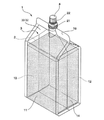
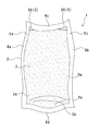
本発明に係る試験液製品の実施の形態について図面に基づいて説明する。先ず、本発明に係る試験液製品1に好適な容器に関して説明を行う。尚、ここで示す試験液製品1の容器は本発明に好適なものであるが、必ずしもこれに限定されるものではなく、金属容器、ガラス容器、各種プラスチック容器、下記以外のプラスチックフィルム袋等、周知の容器を用いることができる。先ず、本発明に好適な容器を用いた試験液製品1の概略斜視図を図5、図6に示す。本発明に係る試験液製品1に好適な容器は、内容物を収容する袋状の容器本体3を備え、この前記容器本体3が、図1〜図4に示す積層フィルム101A〜401Cにより構成されている。そして、本発明に係る試験液製品1は上記の容器に、固形製剤の溶出試験又は崩壊試験に使用する試験液2が充填されている。 An embodiment of the test solution product according to the present invention will be described with reference to the drawings. First, a container suitable for the test liquid product 1 according to the present invention will be described. The container of the test liquid product 1 shown here is suitable for the present invention, but is not necessarily limited to this, and includes metal containers, glass containers, various plastic containers, plastic film bags other than the following, and the like. Well-known containers can be used. First, FIGS. 5 and 6 show schematic perspective views of the test solution product 1 using a container suitable for the present invention. A container suitable for the test liquid product 1 according to the present invention includes a bag-shaped container body 3 for accommodating the contents, and the container body 3 is composed of the laminated films 101A to 401C shown in FIGS. 1 to 4. ing. Then, in the test liquid product 1 according to the present invention, the above-mentioned container is filled with the test liquid 2 used for the dissolution test or the disintegration test of the solid preparation.

ここで、本発明に係る試験液製品1の試験液2は、前述のように、溶出試験液もしくは崩壊試験液であり、それぞれ日本薬局方、米国薬局方、欧州薬局方等に記載されているもの、あるいは別途それらの局法に準じて独自の方法で調製したものなど、特に限定はない。具体的な溶出試験液としては、pH1.2〜8.0の種々のpHの緩衝液、水(精製水)があり、前記緩衝液としては、例えば、第十七改正日本薬局方に記載の溶出試験第1液(pH1.2)、酢酸・酢酸ナトリウム緩衝液(pH4.0)、溶出試験第2液(pH6.8)、リン酸塩緩衝液(pH6.8)、リン酸塩緩衝液(pH8.0)等が挙げられる。また、例えば、第十七改正日本薬局方に記載の崩壊試験法では、崩壊試験液として崩壊試験第1液(pH1.2)、崩壊試験第2液(pH6.8)、水の3種が用いられる。尚、崩壊試験第1液と溶出試験第1液とは同じものが使用されている。よって、試験液2として水または溶出試験第1液が充填された試験液製品1は、崩壊試験用の試験液製品1として用いることもできる。 Here, the test solution 2 of the test solution product 1 according to the present invention is an elution test solution or a disintegration test solution as described above, and is described in the Japanese Pharmacopoeia, the United States Pharmacopeia, the European Pharmacopoeia, etc., respectively. There is no particular limitation on the product, or the product prepared separately according to the local method. Specific dissolution test solutions include buffer solutions having various pH values of 1.2 to 8.0 and water (purified water), and the buffer solutions are described in, for example, the 17th Amendment of the Japanese Pharmacy. Dissolution test 1st solution (pH 1.2), acetic acid / sodium acetate buffer (pH 4.0), dissolution test 2nd solution (pH 6.8), phosphate buffer (pH 6.8), phosphate buffer (PH 8.0) and the like. Further, for example, in the disintegration test method described in the 17th revised Japanese Pharmacopoeia, three types of disintegration test liquids are used: disintegration test first liquid (pH 1.2), disintegration test second liquid (pH 6.8), and water. Used. The same solution as the disintegration test first solution and the dissolution test first solution is used. Therefore, the test liquid product 1 filled with water or the first solution for the dissolution test as the test liquid 2 can also be used as the test liquid product 1 for the disintegration test.

尚、試験液2中に溶存している気体が溶出試験結果に影響を及ぼす場合には、試験の前に脱気する必要がある。そして、本発明に係る試験液製品1の試験液2は、予め所定の脱気度まで脱気したものを用いる。ここで、試験液2の脱気方法として第17改正日本薬局方の記載例では、前述のように「試験液をかき混ぜながら41℃に加温し、直ちに吸引下かき混ぜながら孔径0.45μm以下のフィルターを用いてろ過し、更に、5分間減圧下でかき混ぜる。他のバリデーションされた脱気方法を用いてもよい。」とされている。一方米国における米国薬局方(USP)が発表している産業界向けに発表した「溶出試験ツールキット」には、USP脱気基準として、適量の試験液を41℃から45℃に加温し、0.45μmのメンブレンフィルターにより100mbar以下で減圧ろ過し、さらに5分間減圧下で撹拌すること。また、注意事項として脱気試験液は激しく撹拌したり手荒に扱うと空気の再吸収が早まること、脱気した試験液は速やかに使用することなどが記載されている。また、ほかの脱気法を採用してもよいが、USPの脱気法と同等であること、具体的な脱気度は溶存ガスメーターを使用して、溶存酸素濃度として6ppmを超えてはならないとしている。 If the gas dissolved in the test solution 2 affects the elution test result, it is necessary to degas before the test. The test solution 2 of the test solution product 1 according to the present invention is degassed to a predetermined degassing degree in advance. Here, as a method of degassing the test liquid 2, in the description example of the 17th revised Japanese Pharmacopoeia, as described above, "heat the test liquid to 41 ° C. while stirring, and immediately stir under suction to have a pore size of 0.45 μm or less. Filter using a filter and further stir under reduced pressure for 5 minutes. Other validated degassing methods may be used. " On the other hand, in the "dissolution test tool kit" announced for the industrial world by the United States Pharmacopeia (USP) in the United States, an appropriate amount of test solution is heated from 41 ° C to 45 ° C as a USP degassing standard. Filter under reduced pressure at 100 mbar or less with a 0.45 μm membrane filter, and stir under reduced pressure for another 5 minutes. In addition, as a precaution, it is described that the reabsorption of air is accelerated when the degassed test solution is vigorously agitated or handled roughly, and that the degassed test solution is used promptly. In addition, other degassing methods may be adopted, but they must be equivalent to the USP degassing method, and the specific degree of degassing must not exceed 6 ppm as the dissolved oxygen concentration using a dissolved gas meter. It is supposed to be.

これらのことから、脱気した試験液2の脱気度は溶存酸素濃度として6ppm(6mg/L)以下とすることが求められる。よって、本発明に係る試験液製品1では、充填後の試験液2の液中の空気の溶存量を溶存酸素濃度として0mg/L〜6mg/Lとする。尚、試験液2の脱気方法には特に限定は無く、上述の日本薬局方記載の方法または米国薬局方(USP)記載の方法に加え、例えば市販の各種試験研究用脱気装置、工業用脱気装置の使用、加熱脱気法、減圧脱気法、超音波脱気法、中空糸膜を用いた脱気法、ヘリウム置換等の周知の脱気法を単独もしくは組み合わせて使用する事ができる。そして、この本発明に係る試験液製品1によれば、試験実施者は試験液2を脱気を行うことなく直ちに溶出試験又は崩壊試験に使用することができる。 From these facts, the degree of degassing of the degassed test solution 2 is required to be 6 ppm (6 mg / L) or less as the dissolved oxygen concentration. Therefore, in the test liquid product 1 according to the present invention, the dissolved amount of air in the liquid of the test liquid 2 after filling is set to 0 mg / L to 6 mg / L as the dissolved oxygen concentration. The degassing method of the test solution 2 is not particularly limited, and in addition to the above-mentioned method described in the Japanese Pharmacopoeia or the United States Pharmacopeia (USP), for example, various commercially available degassing devices for testing and research, industrial use. It is possible to use a degassing device, a heating degassing method, a decompression degassing method, an ultrasonic degassing method, a degassing method using a hollow fiber membrane, a well-known degassing method such as helium substitution, alone or in combination. can. According to the test solution product 1 according to the present invention, the tester can immediately use the test solution 2 for the dissolution test or the disintegration test without degassing.

上記のようにして、溶存酸素濃度として6mg/L以下に脱気された試験液2が、周知の容器もしくは図5、図6に示す容器本体3内に充填され試験液製品1が得られる。このとき理想的には容器内に試験液2を全満し、余分な空気(残存空気5)が残らないように、所謂ヘッドスペース30を形成せずに充填し、直ちに密閉することが最も望ましい。何故なら、ヘッドスペース30に残存空気5が存在したまま周知の容器や図5、図6の容器本体3を密閉した場合、その残存空気5が試験液2中に再溶解し脱気度が低下する恐れがあるからである。この残存空気5が試験液2の脱気度に与える影響は、残存空気5の量と脱気した試験液2の相対的な割合に依存する。よって、脱気された試験液2を容器に充填するときの残存空気5の量、即ちヘッドスペース30の容積は厳密に管理される必要がある。 As described above, the test liquid 2 degassed to a dissolved oxygen concentration of 6 mg / L or less is filled in a well-known container or the container body 3 shown in FIGS. 5 and 6 to obtain the test liquid product 1. At this time, ideally, it is most desirable to completely fill the container with the test liquid 2, fill it without forming a so-called head space 30 so that excess air (residual air 5) does not remain, and immediately seal the container. .. This is because when the well-known container or the container body 3 of FIGS. 5 and 6 is sealed with the residual air 5 present in the head space 30, the residual air 5 is redissolved in the test liquid 2 and the degassing degree is lowered. Because there is a risk of doing it. The effect of the residual air 5 on the degree of degassing of the test liquid 2 depends on the amount of the residual air 5 and the relative ratio of the degassed test liquid 2. Therefore, it is necessary to strictly control the amount of the residual air 5 when the degassed test liquid 2 is filled in the container, that is, the volume of the head space 30.

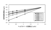
このため本発明者は、残存空気5の量が脱気度に与える影響について以下の実験を行った。先ず、試験液2としての精製水を周知の方法により脱気して、溶存酸素濃度がそれぞれ2.9mg/L、4.5mg/L、5.1mg/L、5.3mg/L、5.4mg/L、6.1mg/Lの試験液2を作製した。次に、容器本体3としての容量1Lのアルミラミネート(アルミ箔を第2の無機物バリア層113cとした後述の積層フィルム101B)のスタンディングパウチ袋に、各溶存酸素濃度の試験液2(精製水)900mLを入れ、脱気シーラーを用いて残存空気5を抜いて満充填とした後、密閉した。次に、注射用シリンジを容器本体3に突き刺し各溶存酸素濃度の試験液2に対して空気を0.0mL(注入無し)、2.5mL、5.0mL、10.0mLそれぞれ注入して残存空気5とし、ヘッドスペース30を形成した。その後、直ちに注入孔をアルミテープで塞ぎ密閉した。次に、これらの試料を10日間室温にて放置した後、開封し試験液2の溶存酸素濃度を測定した。ここで、10日間放置後の試験液2の溶存酸素濃度とヘッドスペース容積比(ヘッドスペース30の容積/試験液の容積)の関係を図7に示す。 Therefore, the present inventor conducted the following experiment on the influence of the amount of residual air 5 on the degree of degassing. First, purified water as test solution 2 is degassed by a well-known method, and the dissolved oxygen concentrations are 2.9 mg / L, 4.5 mg / L, 5.1 mg / L, 5.3 mg / L, and 5. Test solution 2 of 4 mg / L and 6.1 mg / L was prepared. Next, the test liquid 2 (purified water) having each dissolved oxygen concentration was placed in a standing pouch bag of an aluminum laminate having a capacity of 1 L as the container body 3 (a laminated film 101B described later in which the aluminum foil was used as the second inorganic barrier layer 113c). 900 mL was added, and the residual air 5 was evacuated using a degassing sealer to fully fill the mixture, and then the mixture was sealed. Next, an injection syringe is pierced into the container body 3 and 0.0 mL (without injection), 2.5 mL, 5.0 mL, or 10.0 mL of air is injected into the test solution 2 having each dissolved oxygen concentration to inject residual air. The head space 30 was formed at 5. Immediately after that, the injection hole was closed with aluminum tape and sealed. Next, these samples were left at room temperature for 10 days, then opened and the dissolved oxygen concentration of the test solution 2 was measured. Here, FIG. 7 shows the relationship between the dissolved oxygen concentration of the test solution 2 and the headspace volume ratio (volume of the headspace 30 / volume of the test solution) after being left for 10 days.

図7から、ヘッドスペース30の容積、即ち残存空気5の量が多い程、10日間の経時変化後の溶存酸素濃度は上昇することが判る。これは、経時により残存空気5が試験液2中に溶解するためと考えられる。 From FIG. 7, it can be seen that the larger the volume of the head space 30, that is, the amount of the residual air 5, the higher the dissolved oxygen concentration after the change over time for 10 days. It is considered that this is because the residual air 5 dissolves in the test liquid 2 over time.

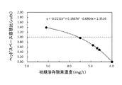
次に、図7のデータから経時変化後の各試料が脱気度の上限値である6mg/Lとなるヘッドスペース30の容積比を近似式から算出し、これらの値をプロットした結果を図8に示す。ここで、図8の横軸は試験液の初期(充填時)の溶存酸素濃度を示し、縦軸はヘッドスペース容積比を示す。そして、試験液2の初期溶存酸素濃度をxとし、ヘッドスペース容積比をyとしたときに、ヘッドスペース容積比の許容値を示す図8のプロットの近似曲線(図8中の破線)は下記(1)式をとる。

y=−0.0231x+0.1867x−0.6804x+2.3516・・(1)

そして、この図8の近似曲線(ヘッドスペースの許容値を示す曲線)よりも下の領域、即ち下記(2)式で表される領域は、ヘッドスペース30の残存空気5が試験液2中に溶解したとしても規定された脱気度である溶存酸素濃度6mg/Lを超えない領域を意味する。

y≦−0.0231x+0.1867x−0.6804x+2.3516・・(2)

よって、本発明に係る試験液製品1は、試験液2の溶存酸素濃度xと容器本体3内のヘッドスペース30の容積比yが(2)式を満たす(図8の近似曲線よりも下の領域に位置する)ものとする。
Next, from the data in FIG. 7, the volume ratio of the head space 30 in which each sample after aging changes to 6 mg / L, which is the upper limit of the degassing degree, is calculated from an approximate formula, and the results of plotting these values are shown in the figure. Shown in 8. Here, the horizontal axis of FIG. 8 shows the dissolved oxygen concentration at the initial stage (at the time of filling) of the test solution, and the vertical axis shows the headspace volume ratio. Then, when the initial dissolved oxygen concentration of the test solution 2 is x and the headspace volume ratio is y, the approximate curve (broken line in FIG. 8) of the plot of FIG. 8 showing the allowable value of the headspace volume ratio is as follows. Take equation (1).

y = -0.0231x 3 + 0.1867x 2 -0.6804x + 2.3516 ·· (1)

Then, in the region below the approximate curve (curve showing the allowable value of the head space) of FIG. 8, that is, the region represented by the following equation (2), the residual air 5 of the head space 30 is contained in the test solution 2. It means a region where the dissolved oxygen concentration of 6 mg / L, which is the specified degassing degree even if dissolved, is not exceeded.

y ≦ -0.0231x 3 + 0.1867x 2 -0.6804x + 2.3516 ·· (2)

Therefore, in the test liquid product 1 according to the present invention, the dissolved oxygen concentration x of the test liquid 2 and the volume ratio y of the head space 30 in the container body 3 satisfy the equation (2) (below the approximate curve of FIG. 8). (Located in the area).

尚、周知の脱気方法で十分に脱気した試験液2の脱気度は概ね溶存酸素濃度4.5mg/L以下を示す。ここで、溶存酸素濃度4.5mg/L時のヘッドスペースの許容値yは上記(1)式より0.97%≒1%となる。よって、通常の脱気操作を行った試験液2は、ヘッドスペース30を試験液2の容量の1%以下、即ち、0vol%〜1vol%とすることで上記(2)式を満たすこととなる。よって、通常の脱気操作を行った試験液2の容器内にヘッドスペース30が形成された場合でも、このヘッドスペース30の容量が1vol%以下であれば、試験液2は経時後も溶存酸素濃度6mg/L以下を維持できる。これにより、試験液製品1におけるヘッドスペース30の良否の基準を簡素化することができる。 The degree of degassing of the test solution 2 sufficiently degassed by a well-known degassing method indicates a dissolved oxygen concentration of 4.5 mg / L or less. Here, the permissible value y of the head space when the dissolved oxygen concentration is 4.5 mg / L is 0.97% ≈ 1% from the above equation (1). Therefore, the test liquid 2 subjected to the normal degassing operation satisfies the above equation (2) by setting the head space 30 to 1% or less of the capacity of the test liquid 2, that is, 0 vol% to 1 vol%. .. Therefore, even when the head space 30 is formed in the container of the test liquid 2 that has undergone the normal degassing operation, if the capacity of the head space 30 is 1 vol% or less, the test liquid 2 has dissolved oxygen even after a lapse of time. A concentration of 6 mg / L or less can be maintained. This makes it possible to simplify the criteria for quality of the head space 30 in the test liquid product 1.

また、周知の容器もしくは容器本体3の容量は、所定量の試験液2を収容可能な範囲内であれば特に限定されないが、試験実施者の負荷の軽減効果、運搬しやすさ等を考慮すると、(試験液2の充填量+30mL)〜(試験液2の充填量+300mL)の範囲内であることが好ましく、(試験液2の充填量+50mL)〜(試験液2の充填量+150mL)の範囲内であることが特に好ましい。例えば、900mLの試験液2を充填する場合は、930〜1200mLであることが好ましく、950〜1050mLであることがより好ましい。尚、周知の容器もしくは容器本体3の容量が、試験液2の充填量+30mL以上であると、容器を開封するときに試験液2の漏れが生じにくく、試験液2の充填量+300mL以下であると、所定量の試験液2を充填したときに、容器が過剰に大きくならず、使用後の廃棄物の量が少ない。 Further, the capacity of the well-known container or the container body 3 is not particularly limited as long as it can accommodate a predetermined amount of the test solution 2, but in consideration of the effect of reducing the load on the tester, the ease of transportation, and the like. , (Filling amount of test solution 2 + 30 mL) to (filling amount of test solution 2 + 300 mL), preferably in the range of (filling amount of test solution 2 + 50 mL) to (filling amount of test solution 2 + 150 mL). It is particularly preferable to be inside. For example, when filling 900 mL of the test solution 2, it is preferably 930 to 1200 mL, and more preferably 950 to 950 mL. If the capacity of the well-known container or container body 3 is the filling amount of the test liquid 2 + 30 mL or more, leakage of the test liquid 2 is unlikely to occur when the container is opened, and the filling amount of the test liquid 2 + 300 mL or less. When the test solution 2 is filled with a predetermined amount, the container does not become excessively large, and the amount of waste after use is small.

そして、試験液2の充填量は、[溶出試験または崩壊試験を1回実施する際に用いる試験液量として規定された容量のn倍]±1%の範囲内(ただしnは1〜6の整数である)であることが好ましく、溶出試験または崩壊試験を1回実施する際に用いる試験液量として規定された容量±1%の範囲内であることが特に好ましい。 The filling amount of the test solution 2 is within the range of [n times the volume specified as the amount of the test solution used when conducting the dissolution test or the disintegration test once] ± 1% (where n is 1 to 6). It is preferably an integer), and is particularly preferably within the range of ± 1% of the volume specified as the amount of test solution used when conducting the dissolution test or the disintegration test once.

そして、nが1の場合、即ち試験液2の充填量が溶出試験または崩壊試験を1回実施する際に用いる容量の±1%の範囲内の場合、試験実施者は周知の容器もしくは容器本体3を開封し、内容液(試験液2)をそのまま試験容器に移し替えるだけで、溶出試験又は崩壊試験を開始することができる。また、充填量が例えば試験の3回分(n=3)2700mLや6回分(N=6)5400mLなどのnが2〜6の場合、試験液製品1から規定の試験液量(例えば、900mL)を正確に小分けする場合の作業が必要になるが、充填量が規定の試験液量の6倍以内であれば、試験液製品1は充分に軽く(例えば、溶出試験の場合、規定の試験液量は最大で900mLであるため、試験液製品1自体の質量が最大で約5400mLである)、運搬、試験液2の小分け等の作業を行いやすい。また、6倍以内であれば、試験液製品1の体積が充分に小さく、前記試験液製品1を予め容器ごと恒温槽等で37℃に加温しておくことが容易である。また、6倍以内であれば、容器の開封後、速やかに試験液2を使い切ることができ、開封後の微生物の汚染や繁殖が生じにくい。特に溶出試験では少なくとも6個の試料について同じ条件で試験を行うため、1度に全量を使い切ることができる。 When n is 1, that is, when the filling amount of the test solution 2 is within ± 1% of the volume used when the dissolution test or the disintegration test is performed once, the tester is a well-known container or container body. The dissolution test or disintegration test can be started simply by opening 3 and transferring the content liquid (test liquid 2) to the test container as it is. Further, when the filling amount is 2 to 6, for example, 2700 mL for 3 times (n = 3) of the test or 5400 mL for 6 times (N = 6), the specified test liquid amount (for example, 900 mL) is applied from the test liquid product 1. However, if the filling amount is within 6 times the specified test solution amount, the test solution product 1 is sufficiently light (for example, in the case of the dissolution test, the specified test solution). Since the maximum amount is 900 mL, the mass of the test solution product 1 itself is a maximum of about 5400 mL), and it is easy to carry out operations such as transportation and subdivision of the test solution 2. Further, if it is within 6 times, the volume of the test liquid product 1 is sufficiently small, and it is easy to preheat the test liquid product 1 together with the container to 37 ° C. in a constant temperature bath or the like. Further, if it is within 6 times, the test solution 2 can be used up immediately after opening the container, and the contamination and propagation of microorganisms after opening are less likely to occur. In particular, in the dissolution test, at least 6 samples are tested under the same conditions, so that the entire amount can be used up at one time.

尚、溶出試験を1回実施する際に用いる試験液量は、日本薬局方等にて製剤毎に規定されているが、通常900mLである。したがって、試験液2が溶出試験液である場合、試験液2の充填量は、汎用性の点から、(900mL×1〜6)±1%の範囲内であることが好ましく、900mL±1%の範囲内であることが特に好ましい。ただし試験液量が900mLではない場合(例えば、500mLの場合)もあり、上記の範囲内に限定されるものではない。規定された各種試験液量に応じた充填量とすることができる。 The amount of test solution used when carrying out the dissolution test once is specified for each pharmaceutical product by the Japanese Pharmacopoeia, etc., but is usually 900 mL. Therefore, when the test solution 2 is an elution test solution, the filling amount of the test solution 2 is preferably in the range of (900 mL × 1 to 6) ± 1%, and 900 mL ± 1% from the viewpoint of versatility. It is particularly preferable that it is within the range of. However, the amount of the test solution may not be 900 mL (for example, 500 mL), and is not limited to the above range. The filling amount can be set according to the specified amount of various test liquids.

また、崩壊試験を1回実施する際に用いる試験液量については、例えば、第十七改正日本薬局方に記載の崩壊試験法では、「ビーカーに入れる試験液の量は、試験器が最も上がったとき、試験器の網面が液面から下へ少なくとも15mm以上離れるようにし、試験器が最も下がったとき、網面はビーカーの底から25mm以上で、試験器が完全に沈むことがあってはならない。」とされ、明確な液量の規定はない。そのため、崩壊試験を1回実施する際に用いる試験液量は、崩壊試験に用いる装置に準じて上記の規定を満たすように試験実施者によって規定され、一般的にはおおよそ900mL前後である。したがって、試験液2が崩壊試験液である場合でも、試験液2の充填量としては(900mL±1%)×1〜6の範囲内であることが好ましく、900mL±1%の範囲内であることが特に好ましい。 Regarding the amount of test solution used when conducting a disintegration test once, for example, in the disintegration test method described in the 17th revised Japanese Pharmacopoeia, "the amount of test solution to be put in the beaker is the highest in the tester. At that time, the mesh surface of the tester should be at least 15 mm below the liquid level, and when the tester is at its lowest position, the mesh surface should be 25 mm or more from the bottom of the beaker, and the tester may sink completely. There is no clear regulation of the amount of liquid. Therefore, the amount of the test solution used when carrying out the disintegration test once is specified by the tester so as to satisfy the above-mentioned regulations according to the apparatus used for the disintegration test, and is generally about 900 mL. Therefore, even when the test solution 2 is a disintegration test solution, the filling amount of the test solution 2 is preferably in the range of (900 mL ± 1%) × 1 to 6, and is in the range of 900 mL ± 1%. Is particularly preferred.

ここで、図5に示す本発明に係る試験液製品1の容器本体3は、いわゆるサイドガゼットタイプのガゼット袋であり、容器本体3の上部に液密に取り付けられたスパウト(口部材)4を有している。そして、図5に示す容器本体3は、第1フィルム11および第2フィルム12と、これら第1フィルム11の一側縁と第2フィルム12の一側縁との間に設けられる第1ガゼットフィルム13と、第1フィルム11の他側縁と第2フィルム12の他側縁との間に設けられる第2ガゼットフィルム14とを備えて構成される。また、第1ガゼットフィルム13と第2ガゼットフィルム14とは、それぞれ容器本体3の内側に向かって屈曲形成されている。そして、第1フィルム11の一側縁と第1ガゼットフィルム13の一側縁とがヒートシールされ、第1ガゼットフィルム13の他側縁と第2フィルム12の一側縁とがヒートシールされ、第2フィルム12の他側縁と第2ガゼットフィルム14の一側縁とがヒートシールされ、第2ガゼットフィルム14の他側縁と第1フィルム11の他側縁とがヒートシールされて、4本の側縁シール部が形成されている。また、上部において第1フィルム11、第2フィルム12、第1ガゼットフィルム13、第2ガゼットフィルム14の内面同士がヒートシールされて上部シール部16が形成されている。また、下部において第1フィルム11、第2フィルム12、第1ガゼットフィルム13、第2ガゼットフィルム14の内面同士がヒートシールされて下部シール部が形成されている。 Here, the container body 3 of the test liquid product 1 according to the present invention shown in FIG. 5 is a so-called side gusset type gusset bag, and a spout (mouth member) 4 liquidally attached to the upper part of the container body 3 is provided. Have. The container body 3 shown in FIG. 5 is a first gusset film provided between the first film 11 and the second film 12 and one side edge of the first film 11 and one side edge of the second film 12. 13 is provided with a second gusset film 14 provided between the other side edge of the first film 11 and the other side edge of the second film 12. Further, the first gusset film 13 and the second gusset film 14 are each bent toward the inside of the container body 3. Then, one side edge of the first film 11 and one side edge of the first gusset film 13 are heat-sealed, and the other side edge of the first gusset film 13 and one side edge of the second film 12 are heat-sealed. The other side edge of the second film 12 and one side edge of the second gusset film 14 are heat-sealed, and the other side edge of the second gusset film 14 and the other side edge of the first film 11 are heat-sealed. A side edge seal portion of the book is formed. Further, in the upper part, the inner surfaces of the first film 11, the second film 12, the first gusset film 13, and the second gusset film 14 are heat-sealed to each other to form the upper seal portion 16. Further, in the lower portion, the inner surfaces of the first film 11, the second film 12, the first gusset film 13, and the second gusset film 14 are heat-sealed to each other to form a lower seal portion.

尚、上部シール部16においては、第1ガゼットフィルム13の接触面同士、第2ガゼットフィルム14の接触面同士がそれぞれシールされることが好ましい。上部シール部16における第1ガゼットフィルム13、第2ガゼットフィルム14それぞれの接触面同士のシールは、例えば、第1ガゼットフィルム13、第2ガゼットフィルム14それぞれの側縁近傍における対向する位置に図示しないパンチ穴が形成され、前記パンチ穴内で第1フィルム11の内面と第2フィルム12の内面とがヒートシールされることで行われる。また、上部シール部16における第1ガゼットフィルム13の接触面同士、第2ガゼットフィルム14の接触面同士は、それぞれ、接着剤、ヒートシール性を有するフィルムを使用したヒートシール、又は両面粘着テープにより直接接着されていてもよい。 In the upper sealing portion 16, it is preferable that the contact surfaces of the first gusset film 13 and the contact surfaces of the second gusset film 14 are sealed with each other. The seals between the contact surfaces of the first gusset film 13 and the second gusset film 14 in the upper sealing portion 16 are not shown at, for example, opposite positions near the side edges of the first gusset film 13 and the second gusset film 14. A punch hole is formed, and the inner surface of the first film 11 and the inner surface of the second film 12 are heat-sealed in the punch hole. Further, the contact surfaces of the first gusset film 13 and the contact surfaces of the second gusset film 14 in the upper sealing portion 16 are made of an adhesive, a heat seal using a film having a heat seal property, or a double-sided adhesive tape, respectively. It may be directly bonded.

そして、これら第1フィルム11、第2フィルム12、第1ガゼットフィルム13、第2ガゼットフィルム14はそれぞれ、後述の積層フィルム101A〜101C、201A〜201C、301A〜301C、401A〜401Cにより構成される。 The first film 11, the second film 12, the first gusset film 13, and the second gusset film 14 are composed of laminated films 101A to 101C, 201A to 201C, 301A to 301C, and 401A to 401C, which will be described later, respectively. ..

また、スパウト4は、容器本体3内に挿入され、内容物(試験液2)を注出する注出管21と、注出管21の上部に螺合せしめて、注出管21の注出口を密閉するキャップ22とを有する。尚、スパウト4は、注出管21が第1フィルム11、第2フィルム12の上縁部同士で挟持された状態で、ヒートシールにより上部シール部16に液密に取り付けられている。そして、キャップ22が装着された状態では、容器本体3が密閉状態となる。また、キャップ22が外されている状態では、注出管21により容器本体3の内部と外部とが連通する。そして、図5に示す試験液製品1は、キャップ22付きのスパウト4を備えることから開封・封止が容易であり、また内容物(試験液2)の溶出試験用ガラスベッセル等への投入が容易であり、試験の準備時間の短縮に有用である。尚、スパウト4には、一旦開封されたら、開封された証拠が残るタンパーエビデント付きの口栓構造を採用することが好ましい。一旦開封された試験液製品1においては、収容されている試験液のpHが変化しやすくなる。よって、タンパーエビデント付きの口栓構造を採用することにより、試験液製品1の開封の有無が確認でき、試験液2の品質を保証することができる。 Further, the spout 4 is inserted into the container body 3 and screwed into the spouting pipe 21 for pouring out the contents (test solution 2) and the upper part of the spouting pipe 21 to make the spout of the pouring pipe 21. It has a cap 22 for sealing. The spout 4 is liquidtightly attached to the upper seal portion 16 by heat sealing in a state where the spout pipe 21 is sandwiched between the upper edges of the first film 11 and the second film 12. When the cap 22 is attached, the container body 3 is sealed. Further, in the state where the cap 22 is removed, the inside and the outside of the container body 3 communicate with each other by the pouring pipe 21. Since the test liquid product 1 shown in FIG. 5 is provided with a spout 4 with a cap 22, it is easy to open and seal, and the content (test liquid 2) can be put into a glass vessel or the like for an elution test. It is easy and useful for reducing test preparation time. It is preferable that the spout 4 adopts a spout structure with a tamper evidence in which evidence of opening remains once the spout 4 is opened. In the test solution product 1 once opened, the pH of the contained test solution is likely to change. Therefore, by adopting the spout structure with tamper evidence, it is possible to confirm whether or not the test liquid product 1 has been opened, and it is possible to guarantee the quality of the test liquid 2.

スパウト4の材質としては、少なくとも、注出管21の第1フィルム11、第2フィルム12の内面とシールされる部分は合成樹脂である。そして、スパウト4の注出管21の少なくともシール部分を形成する合成樹脂としては、例えば、ポリオレフィン樹脂、ポリアミド樹脂、ポリエステル樹脂、(メタ)アクリル樹脂、塩化ビニル樹脂、塩化ビニリデン樹脂、ポリエーテルサルホン、エチレン−ビニルアルコール共重合体等が挙げられる。なかでも、加工性に優れ、低コストである点から、ポリオレフィン樹脂が好ましい。さらに、ポリオレフィン樹脂としては、例えば、高密度ポリエチレン、中密度ポリエチレン、高圧法低密度ポリエチレン、直鎖状低密度ポリエチレン、エチレン−酢酸ビニル共重合体等のポリエチレン系樹脂、エチレン−α−オレフィン共重合体等のオレフィン系エラストマー、ポリプロピレン、エチレン−プロピレンランダム共重合体、α−オレフィン−プロピレンランダム共重合体等のポリプロピレン系樹脂や、環状ポリオレフィン樹脂等が挙げられる。これらの樹脂は、性能向上のためにブレンドされていてもよく、耐熱性向上等を目的として一部架橋されていてもよい。また、スパウト4は単一の材料から形成されていてもよく、あるいは種々の樹脂層からなる多層構造が形成されていてもよい。ただし、スパウト4の注出管21の少なくともシール部分を形成する樹脂は、シール性の点から、第1フィルム11の最内層、第2フィルム12の最内層を形成する樹脂と同種の樹脂で形成することが好ましい。 As the material of the spout 4, at least the portion of the spout pipe 21 to be sealed with the inner surfaces of the first film 11 and the second film 12 is a synthetic resin. Examples of the synthetic resin forming at least the sealing portion of the injection pipe 21 of the spout 4 include a polyolefin resin, a polyamide resin, a polyester resin, a (meth) acrylic resin, a vinyl chloride resin, a vinylidene chloride resin, and a polyether sulfone. , Ethylene-vinyl alcohol copolymer and the like. Of these, polyolefin resins are preferable because they are excellent in processability and low in cost. Further, examples of the polyolefin resin include high-density polyethylene, medium-density polyethylene, high-pressure low-density polyethylene, linear low-density polyethylene, polyethylene-based resins such as ethylene-vinyl acetate copolymer, and ethylene-α-olefin co-weight. Examples thereof include an olefin-based elastomer such as a coalescence, a polypropylene-based resin such as polypropylene, an ethylene-propylene random copolymer, an α-olefin-propylene random copolymer, and a cyclic polyolefin resin. These resins may be blended for the purpose of improving the performance, or may be partially crosslinked for the purpose of improving the heat resistance and the like. Further, the spout 4 may be formed of a single material, or may have a multilayer structure composed of various resin layers. However, the resin forming at least the sealing portion of the spout pipe 21 of the spout 4 is formed of the same kind of resin as the resin forming the innermost layer of the first film 11 and the innermost layer of the second film 12 from the viewpoint of sealing property. It is preferable to do so.

また、図6に示す本発明に係る試験液製品1の容器本体3は、一対のフィルムからなる胴部3aと、フィルムからなる底部3bとを有するスタンディングパウチである。また、胴部3aを構成する一対のフィルムは、側縁部、上縁部で溶着され、側縁シール部4a、4b、上縁シール部4cが形成されている。また、底部3bを構成するフィルムは、半折された状態で、胴部3aを構成する一対のフィルムの間に、半折した折り線が上となるように配置され、底部3bを構成するフィルムの折り線を境界とした一方の面、他方の面がそれぞれ、胴部3aを構成する一対のフィルムのうち対向するフィルムの下縁部に溶着され、下縁シール部4d、4eが形成されている。尚、側縁シール部4a、4bと、下縁シール部4d、4eとが重なる領域では、胴部3aを構成する一対のフィルム同士が部分的に溶着している。さらに、側縁シール部4a、4bには、それぞれ、上縁シール部4cの下端よりわずかに下側に、容器本体3を開封しやすくするために、切り欠き5a、5bが設けられている。そして、胴部3aを構成する一対のフィルム及び底部3bを構成するフィルムとして、後述の積層フィルム101A〜101C、201A〜201C、301A〜301C、401A〜401Cが用いられる。 Further, the container body 3 of the test liquid product 1 according to the present invention shown in FIG. 6 is a standing pouch having a body portion 3a made of a pair of films and a bottom portion 3b made of a film. Further, the pair of films constituting the body portion 3a are welded at the side edge portion and the upper edge portion, and the side edge sealing portions 4a and 4b and the upper edge sealing portion 4c are formed. Further, the film constituting the bottom portion 3b is arranged in a half-folded state between the pair of films constituting the body portion 3a so that the half-folded fold line is on the top, and constitutes the bottom portion 3b. One surface and the other surface with the fold line as a boundary are welded to the lower edge portion of the opposite film among the pair of films constituting the body portion 3a, respectively, to form the lower edge sealing portions 4d and 4e. There is. In the region where the side edge sealing portions 4a and 4b and the lower edge sealing portions 4d and 4e overlap, the pair of films constituting the body portion 3a are partially welded to each other. Further, the side edge sealing portions 4a and 4b are provided with cutouts 5a and 5b slightly below the lower end of the upper edge sealing portion 4c, respectively, in order to facilitate opening of the container body 3. Then, as the pair of films constituting the body portion 3a and the films constituting the bottom portion 3b, the laminated films 101A to 101C, 201A to 201C, 301A to 301C, and 401A to 401C described later are used.

尚、容器本体3を形成する積層フィルム101A〜401Cの層構成は同じであっても異なっていてもよいが、それらの積層フィルム101A〜401C同士のヒートシールが容易になる点から、ともに同種の樹脂からなるシーラントフィルム111を含む積層フィルム101A〜401Cを用いることが好ましい。 The layered structures of the laminated films 101A to 401C forming the container body 3 may be the same or different, but they are the same type in that heat sealing between the laminated films 101A to 401C is easy. It is preferable to use laminated films 101A to 401C containing a sealant film 111 made of a resin.

尚、本発明に係る試験液製品1の容器本体3は前述のように図5、図6に示す形態に限定されない。例えば、図5に示す容器本体3とは異なる形状のガゼット袋であってもよく、ガゼット袋以外の袋であってもよい。また、図6に示す容器本体3とは異なる形状のスタンディングパウチであってもよく、スタンディングパウチ以外の袋であってもよい。また、金属、ガラス、各種プラスチック製の瓶等、周知の容器としても良い。ただし、作業効率の向上効果の点では、容器が自立可能なものであることが好ましく、図5、図6の容器本体3のようにガゼット袋またはスタンディングパウチであることがより好ましい。ガゼット袋またはスタンディングパウチ以外の容器本体3としては、例えば、三方シール袋、四方シール袋、開封しやすいように切り口が付いた袋(例えばノッチ付き三方シール袋)などの平袋が挙げられる。また、容器本体3は積層フィルム101A〜401Cから構成される袋状の容器本体3のみからなるものであってもよいし、スパウト付き容器であってもよい。ただし、試験液2の取り出しやすさ、試験液2取り出し後の廃棄物の少なさ等の点で、スパウト4を備えた袋状の容器本体3が好ましい。この構成では容器本体3がキャップ22付きのスパウト4を備えることから、開封・封止が容易であり、また溶出試験用ガラスベッセル等への試験液2の投入が容易となり、試験の準備時間をさらに短縮することができる。 The container body 3 of the test liquid product 1 according to the present invention is not limited to the form shown in FIGS. 5 and 6 as described above. For example, a gusset bag having a shape different from that of the container body 3 shown in FIG. 5 may be used, or a bag other than the gusset bag may be used. Further, the standing pouch may have a shape different from that of the container body 3 shown in FIG. 6, or may be a bag other than the standing pouch. Further, a well-known container such as a metal, glass, or various plastic bottles may be used. However, in terms of the effect of improving work efficiency, it is preferable that the container is self-supporting, and it is more preferable that the container is a gusset bag or a standing pouch as in the container body 3 of FIGS. 5 and 6. Examples of the container body 3 other than the gusset bag or the standing pouch include a flat bag such as a three-way seal bag, a four-way seal bag, and a bag with a cut end for easy opening (for example, a notched three-way seal bag). Further, the container body 3 may be composed of only the bag-shaped container body 3 composed of the laminated films 101A to 401C, or may be a container with a spout. However, the bag-shaped container body 3 provided with the spout 4 is preferable in terms of ease of taking out the test liquid 2 and the small amount of waste after taking out the test liquid 2. In this configuration, since the container body 3 is provided with the spout 4 with the cap 22, it is easy to open and seal the container, and it is easy to put the test liquid 2 into the glass vessel for the dissolution test or the like, so that the test preparation time can be increased. It can be further shortened.

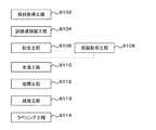
次に、図5、図6に示す本発明に係る試験液製品1の製造方法の一例を図9のフローチャートを用いて説明する。先ず、試験液2を製造するための精製水、無機塩、塩酸などの材料を準備する(原料取得工程S102)。次に、これらの材料を計量して耐薬品性を有するPE(ポリエチレン)、PP(ポリプロピレン)、SUS316L製などの仕込みタンク等に投入し、例えば攪拌溶解させるなどして目的の試験液2を日本薬局方等の規定に従って調製する(試験液調製行程S104)。次に、試験液2に対して脱気を行う(脱気工程S106)。この脱気には、周知の各種試験研究用脱気装置、工業用脱気装置、脱気モジュール等を使用する事ができる。そして、この脱気工程S106により試験液2は溶存酸素濃度4.5mg/L以下の脱気度に脱気される。 Next, an example of the manufacturing method of the test liquid product 1 according to the present invention shown in FIGS. 5 and 6 will be described with reference to the flowchart of FIG. First, materials such as purified water, an inorganic salt, and hydrochloric acid for producing the test liquid 2 are prepared (raw material acquisition step S102). Next, these materials are weighed and put into a charging tank made of PE (polyethylene), PP (polypropylene), SUS316L, etc., which has chemical resistance, and the target test liquid 2 is added to Japan by, for example, stirring and dissolving. Prepare according to the regulations of the Pharmacopoeia (test solution preparation process S104). Next, the test liquid 2 is degassed (degassing step S106). For this degassing, various well-known test and research degassing devices, industrial degassing devices, degassing modules, and the like can be used. Then, in this degassing step S106, the test liquid 2 is degassed to a degassing degree of a dissolved oxygen concentration of 4.5 mg / L or less.

また、これと並行して積層フィルム101A〜401Cを用いた容器本体3が準備される(容器取得工程S108)。尚、試験液2を充填する容器本体3は、積層フィルム101A〜401Cを用いていれば市販のものでも良く、また、積層フィルム101A〜401Cを用いて作製してもよい。尚、容器及び容器本体3の作製方法は特に限定されず、公知の方法により実施できる。 Further, in parallel with this, the container main body 3 using the laminated films 101A to 401C is prepared (container acquisition step S108). The container body 3 filled with the test liquid 2 may be a commercially available product as long as the laminated films 101A to 401C are used, or may be manufactured using the laminated films 101A to 401C. The method for producing the container and the container body 3 is not particularly limited, and can be carried out by a known method.

そして、この容器本体3に予め設定された量±1%(例えば900mL±1%)の試験液2を例えばチューブポンプやシリンジポンプ等の周知の液体充填装置を用いて充填する(充填工程S110)。次に、容器本体3がスパウト4を有する場合には、例えば真空キャッパー等の周知の密閉部材を用いて容器本体3内の残存空気5を抜くとともにキャップ22付のスパウト4を固定して容器本体3を密閉する。また、容器本体3がスパウト4を有さないものの場合には、例えば真空シーラー等の周知の密閉部材を用いて容器本体3内の残存空気5を抜くとともに容器本体3の開口部をシールして容器本体3を密閉する。このとき、容器本体3内の残存空気5、即ちヘッドスペース30の体積は試験液2の容量の1%以下とする(密閉工程S112)。尚、試験液2の溶存酸素濃度は4.5mg/L以下であるから、ヘッドスペース30の体積を試験液2の容量の1%以下とすることで、仮にヘッドスペース30の残存空気5が試験液2中に溶解したとしても、試験液2の溶存酸素濃度が規定値の6.0mg/Lを超えることはない。 Then, the container body 3 is filled with a preset amount ± 1% (for example, 900 mL ± 1%) of the test liquid 2 using a well-known liquid filling device such as a tube pump or a syringe pump (filling step S110). .. Next, when the container body 3 has the spout 4, the residual air 5 in the container body 3 is removed by using a well-known sealing member such as a vacuum capper, and the spout 4 with the cap 22 is fixed to fix the container body 3. 3 is sealed. When the container body 3 does not have the spout 4, for example, a well-known sealing member such as a vacuum sealer is used to remove the residual air 5 in the container body 3 and seal the opening of the container body 3. Seal the container body 3. At this time, the volume of the residual air 5 in the container body 3, that is, the head space 30 is set to 1% or less of the volume of the test liquid 2 (sealing step S112). Since the dissolved oxygen concentration of the test liquid 2 is 4.5 mg / L or less, by setting the volume of the head space 30 to 1% or less of the volume of the test liquid 2, the residual air 5 of the head space 30 is tentatively tested. Even if it is dissolved in the liquid 2, the dissolved oxygen concentration of the test liquid 2 does not exceed the specified value of 6.0 mg / L.

次に、必要であればこの密閉工程S112後の製品に滅菌処理を行ってもよい(減菌工程S113)。この滅菌処理は、例えば120℃、30分〜60分間の湿熱殺菌の条件で実施することができる。次に、容器本体3の表面に内容物を示すラベル等が貼付され(ラベリング工程S114)、本発明に係る試験液製品1が完成する。 Next, if necessary, the product after the sealing step S112 may be sterilized (sterilization step S113). This sterilization process can be carried out under the conditions of moist heat sterilization at 120 ° C. for 30 to 60 minutes, for example. Next, a label or the like indicating the contents is affixed to the surface of the container body 3 (labeling step S114), and the test liquid product 1 according to the present invention is completed.

次に、本発明に係る試験液製品1に用いる積層フィルムに関して説明を行う。尚、ここで「(メタ)アクリル酸」は、アクリル酸及びメタクリル酸の総称である。また、「〜」を用いて表される数値範囲は、「〜」の両側の数値をその数値範囲に含むものとする。 Next, the laminated film used for the test liquid product 1 according to the present invention will be described. Here, "(meth) acrylic acid" is a general term for acrylic acid and methacrylic acid. In addition, the numerical range represented by using "~" shall include the numerical values on both sides of "~" in the numerical range.

[積層フィルム]
〈第1の実施形態〉
《第1の実施形態の基本形》
本発明の積層フィルムの第1の実施形態を、図1Aを適宜参照しながら説明する。なお、後述する変形例と区別するため、図1Aに示す実施形態を、特に、「基本形」という場合がある。
[Laminated film]
<First embodiment>
<< Basic form of the first embodiment >>
A first embodiment of the laminated film of the present invention will be described with reference to FIG. 1A as appropriate. The embodiment shown in FIG. 1A may be particularly referred to as a "basic form" in order to distinguish it from a modification described later.

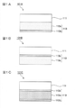
本実施形態の積層フィルム101Aは、シーラントフィルム111と、バリアフィルム113とを含む。本基本形のバリアフィルム113は、べースフィルム113aのシーラントフィルム111に対向する面とは反対側の面に第1の無機物バリア層113bを有する。本実施形態の積層フィルム101Aでは、シーラントフィルム111と、バリアフィルム113とは、直接もしくは有機溶剤を含まない無溶剤接着層を介して積層されている。換言すれば、シーラントフィルム111と、バリアフィルム113との間には、有機溶剤を含む接着剤及びアンカーコート剤のいずれも含まない。 The laminated film 101A of the present embodiment includes the sealant film 111 and the barrier film 113. The barrier film 113 of the present basic form has a first inorganic barrier layer 113b on a surface of the base film 113a opposite to the surface facing the sealant film 111. In the laminated film 101A of the present embodiment, the sealant film 111 and the barrier film 113 are laminated directly or via a solvent-free adhesive layer containing no organic solvent. In other words, neither the adhesive containing an organic solvent nor the anchor coating agent is contained between the sealant film 111 and the barrier film 113.

(シーラントフィルム111)
本実施形態のシーラントフィルム111は、積層フィルム101Aにヒートシール性を付与する層であり、積層フィルム101Aをヒートシールにより袋状(容器本体3の形状)とする際に加熱により溶融し、積層フィルム101Aと、シーラントフィルム111に接する他のフィルムとを接着する。尚、シーラントフィルム111は、酸化防止剤・滑剤・アンチブロッキング剤等が添加されていない無添加ポリオレフィンからなる。そして、本実施形態の積層フィルム101Aを用いて試験液製品1を構成した場合に、シーラントフィルム111が内容物である試験液2と接触する。ここで、従来の(無添加ではない)シーラントフィルムは紫外線吸収を有するBHA(ブチルヒドロキシアニソール)又はBHT(ジブチルヒドロキシトルエン)等の酸化防止剤が配合されていたため、これらの紫外線吸収成分が試験液2に溶出してしまい、溶出試験や崩壊試験の結果に悪影響を与える場合があった。しかし、本実施形態の積層フィルム101Aでは、無添加ポリオレフィンからなるシーラントフィルム111を用いるので、試験液2に紫外線吸収成分が溶出することがない。
(Sealant film 111)
The sealant film 111 of the present embodiment is a layer that imparts heat-sealing property to the laminated film 101A, and is melted by heating when the laminated film 101A is formed into a bag shape (shape of the container body 3) by heat sealing, and is a laminated film. The 101A and another film in contact with the sealant film 111 are adhered to each other. The sealant film 111 is made of additive-free polyolefin to which an antioxidant, a lubricant, an antiblocking agent, or the like is not added. Then, when the test liquid product 1 is constructed by using the laminated film 101A of the present embodiment, the sealant film 111 comes into contact with the test liquid 2 which is the content. Here, since the conventional (not additive-free) sealant film contains an antioxidant such as BHA (butylhydroxyanisole) or BHT (dibutylhydroxytoluene) having ultraviolet absorption, these ultraviolet absorbing components are used as a test solution. In some cases, it was eluted in 2 and adversely affected the results of the dissolution test and the disintegration test. However, in the laminated film 101A of the present embodiment, since the sealant film 111 made of additive-free polyolefin is used, the ultraviolet absorbing component does not elute into the test liquid 2.

また、無添加ポリオレフィンは、紫外線吸収成分の試験液2への溶出が無いほか、ヒートシール性を有し、試験液2が吸着しにくいという特徴も有する。無添加ポリオレフィンとしては、無添加高密度ポリエチレン(無添加HDPE)、無添加低密度ポリエチレン(無添加LDPE)、無添加直鎖状低密度ポリエチレン(無添加LLDPE)等の無添加ポリエチレン、無添加ポリプロピレン、無添加ポリブテン等が挙げられる。これらの中でも、低温でヒートシールできることから、無添加ポリエチレンが好ましく、高強度であることから、無添加LLDPEが特に好ましい。 Further, the additive-free polyolefin has the characteristics that the ultraviolet absorbing component does not elute into the test liquid 2 and also has a heat-sealing property, so that the test liquid 2 is difficult to be adsorbed. Examples of the additive-free polyolefin include additive-free polyethylene such as additive-free high-density polyethylene (additive-free HDPE), additive-free low-density polyethylene (additive-free LDPE), and additive-free linear low-density polyethylene (additive-free LLDPE), and additive-free polypropylene. , Additive-free polybutene and the like. Among these, additive-free polyethylene is preferable because it can be heat-sealed at a low temperature, and additive-free LLDPE is particularly preferable because it has high strength.

シーラントフィルム111の厚みは特に限定されないが、通常、20〜300μm程度である。シーラントフィルム111は、無添加ポリオレフィンのフィルムの1枚からなるものであってもよいし、無添加ポリオレフィンのフィルムの2枚以上を直接もしくは有機溶剤を含まない無溶剤接着層を介して積層したものであってもよい。この場合、無添加ポリオレフィンのフィルムとフィルムの間には、有機溶剤を含む接着剤及びアンカーコート剤のいずれも含まない。 The thickness of the sealant film 111 is not particularly limited, but is usually about 20 to 300 μm. The sealant film 111 may consist of one film of additive-free polyolefin, or two or more films of additive-free polyolefin laminated directly or via a solvent-free adhesive layer containing no organic solvent. It may be. In this case, neither the adhesive containing an organic solvent nor the anchor coating agent is contained between the films of the additive-free polyolefin.

(バリアフィルム113)
バリアフィルム113は、水蒸気バリア性等のガスバリア性に優れたフィルムであり、これを含む本実施形態の積層フィルム101Aも優れたガスバリア性を有する。そして、積層フィルム101Aで構成された容器本体3に試験液2を充填することで、試験液製品1を保管している間の試験液2中の水の蒸発が抑制され、試験液製品1を、試験液2量を減少させることなく長期間安定に保管することができる。また、試験液2が脱気されたものの場合、試験液2に容器本体3の外部からの大気の再溶解を抑制し、脱気度の低下を抑制することができる。
(Barrier film 113)
The barrier film 113 is a film having excellent gas barrier properties such as water vapor barrier properties, and the laminated film 101A of the present embodiment including the barrier film 113 also has excellent gas barrier properties. Then, by filling the container body 3 made of the laminated film 101A with the test liquid 2, evaporation of water in the test liquid 2 during storage of the test liquid product 1 is suppressed, and the test liquid product 1 is used. , The test solution 2 can be stably stored for a long period of time without reducing the amount. Further, when the test liquid 2 is degassed, it is possible to suppress the redissolution of the atmosphere from the outside of the container body 3 in the test liquid 2 and suppress the decrease in the degree of degassing.

べースフィルム113aは熱可塑性樹脂からなる。べースフィルム113aに用いる熱可塑性樹脂としては、フィルム強度、突刺し強度、透明性等の点から、ポリエチレンテレフタレート(PET)、ポリエチレン−2,6−ナフタレート(PEN)等のポリエステル樹脂、ナイロン6、ナイロン66、ナイロン12、共重合ナイロン等のポリアミド樹脂が挙げられる。また、べースフィルム113aとしては、これらの熱可塑性樹脂を原料とする未延伸又は延伸のフィルムが好ましい。特に、寸法安定性に優れ、蒸着膜にクラックが入り難いことから、ポリエステル樹脂が好ましい。そして、べースフィルム113aに酸化防止剤・滑剤・アンチブロッキング剤等が無添加の熱可塑性樹脂を用いると、試験液2に紫外線吸収成分が溶出することがない。また、べースフィルム113aは、無添加の熱可塑性樹脂のフィルムの1枚からなるものであってもよいし、無添加の熱可塑性樹脂のフィルムの2枚以上を直接もしくは有機溶剤を含まない無溶剤接着層により積層したものであってもよい。この場合、無添加の熱可塑性樹脂のフィルムとフィルムの間には、有機溶剤を含む接着剤及びアンカーコート剤のいずれも含まない。 The base film 113a is made of a thermoplastic resin. The thermoplastic resin used for the base film 113a includes polyester resins such as polyethylene terephthalate (PET) and polyethylene-2,6-naphthalate (PEN), nylon 6, and nylon in terms of film strength, piercing strength, transparency, and the like. Polyamide resins such as 66, nylon 12, and copolymerized nylon can be mentioned. Further, as the base film 113a, an unstretched or stretched film made from these thermoplastic resins as a raw material is preferable. In particular, a polyester resin is preferable because it has excellent dimensional stability and the vapor-filmed film is less likely to crack. When a thermoplastic resin containing no antioxidant, lubricant, antiblocking agent or the like is used for the base film 113a, the ultraviolet absorbing component does not elute into the test liquid 2. Further, the base film 113a may be made of one of the additive-free thermoplastic resin films, or two or more of the additive-free thermoplastic resin films may be directly or solvent-free without containing an organic solvent. It may be laminated by an adhesive layer. In this case, neither the adhesive containing an organic solvent nor the anchor coating agent is contained between the films of the additive-free thermoplastic resin.

第1の無機物バリア層113bは、金属箔、金属の蒸着膜又は無機酸化物の蒸着膜であることが好ましい。また、前記金属箔は、アルミニウム、クロム、亜鉛、金、銀、プラチナ及びニッケルからなる群から選択される少なくとも1種の金属の箔が好ましく、アルミニウム箔がより好ましい。尚、前記金属は1種でも2種以上でもよい。前記金属箔の厚みは、5〜200μmが好ましく、15〜20μmがより好ましい。前記金属箔の厚みが上記範囲内であると、積層フィルム101Aのバリア性が良好であり、かつ、可撓性も良好になる。 The first inorganic barrier layer 113b is preferably a metal foil, a metal vapor deposition film, or an inorganic oxide vapor deposition film. Further, the metal foil is preferably a foil of at least one metal selected from the group consisting of aluminum, chromium, zinc, gold, silver, platinum and nickel, and more preferably an aluminum foil. The metal may be one kind or two or more kinds. The thickness of the metal foil is preferably 5 to 200 μm, more preferably 15 to 20 μm. When the thickness of the metal foil is within the above range, the barrier property of the laminated film 101A is good and the flexibility is also good.

前記金属の蒸着膜は、アルミニウム、クロム、亜鉛、金、銀、プラチナ及びニッケルからなる群から選択される少なくとも1種の金属の蒸着膜が好ましく、アルミニウム蒸着膜がより好ましい。尚、前記金属は1種でも2種以上でもよい。前記金属の蒸着膜の厚みは、5〜300nmが好ましく、10〜100nmがより好ましい。尚、前記金属の蒸着膜の厚みは、水晶振動子型膜厚モニタや分光光度計により測定される。前記金属の蒸着膜の厚みが上記範囲内であると、積層フィルム101Aのバリア性が良好であり、かつ、可撓性も良好になる。そして、前記金属の蒸着膜は、例えば、真空蒸着法、スパッタリング法、化学蒸着法、イオンプレーテング法等の方法により金属をベースフィルム113aの表面に蒸着して形成できる。 The metal vapor deposition film is preferably a vapor deposition film of at least one metal selected from the group consisting of aluminum, chromium, zinc, gold, silver, platinum and nickel, and more preferably an aluminum vapor deposition film. The metal may be one kind or two or more kinds. The thickness of the metal vapor deposition film is preferably 5 to 300 nm, more preferably 10 to 100 nm. The thickness of the metal vapor deposition film is measured by a crystal oscillator type film thickness monitor or a spectrophotometer. When the thickness of the metal vapor-deposited film is within the above range, the barrier property of the laminated film 101A is good and the flexibility is also good. The metal vapor deposition film can be formed by depositing metal on the surface of the base film 113a by, for example, a vacuum vapor deposition method, a sputtering method, a chemical vapor deposition method, an ion plating method, or the like.

前記無機酸化物の蒸着膜は、金属酸化物、フッ化物、硫化物及び窒化物からなる群から選択される少なくとも1種の無機酸化物の蒸着膜が好ましい。前記金属酸化物としては、Al(酸化アルミニウム、アルミナ)、SnO(酸化スズ)、CeO(酸化セリウム)、Ta(五酸化タンタル)、Cr(酸化クロム)、Ti(五酸化チタン)、Ga(酸化ガリウム)、TiO(一酸化チタン)、Fe(酸化鉄)、TiO(二酸化チタン−チタニア)、HfO(酸化ハフニウム、ハフニア)、WO(酸化タングステン)、ITO(In+SnO)、Y(酸化イットリウム、イットリア)、MgO(酸化マグネシウム、マグネシア)、Yb(酸化イッテルビウム)、Nb(五酸化ニオブ)、ZnO(酸化亜鉛)、NiO(酸化ニッケル)、ZrO(酸化ジルコニウム−ジルコニア)、SiO(一酸化ケイ素)、ZRT(Zr0+TiO)、SiO(酸化ケイ素)等が挙げられる。これらの中でも、蒸着膜の透明性の高さ、入手しやすさ等から、酸化ケイ素、酸化アルニウム又は酸化マグネシウムが好ましく、酸化ケイ素又は酸化アルミニウムがより好ましい。前記無機酸化物は1種でも2種以上でもよい。また、前記無機酸化物の蒸着膜の厚みは、5〜300nmが好ましく、10〜100nmがより好ましい。尚、前記無機酸化物の蒸着膜の厚みは、水晶振動子型膜厚モニタや分光光度計により測定される。そして、前記無機酸化物の蒸着膜は、例えば、真空蒸着法、スパッタリング法、化学蒸着法、イオンプレーテング法等の方法により無機酸化物をベースフィルム113aの表面に蒸着して形成できる。 The thin-film film of the inorganic oxide is preferably a thin-film film of at least one inorganic oxide selected from the group consisting of metal oxides, fluorides, sulfides and nitrides. Examples of the metal oxide include Al 2 O 3 (aluminum oxide, alumina), SnO 2 (tin oxide), CeO 2 (cerium oxide), Ta 2 O 5 (tantalum pentoxide), and Cr 2 O 3 (chromium oxide). , Ti 3 O 5 (tantalum pentoxide), Ga 2 O 3 (gallium oxide), TiO (titanium monoxide), Fe 2 O 3 (iron oxide), TiO 2 (titalum dioxide-titania), HfO 2 (hafonium oxide) , Hafnia), WO 3 (titanium oxide), ITO (In 2 O 3 + SnO 2 ), Y 2 O 3 (yttrium oxide, itria), MgO (magnesia oxide, magnesia), Yb 2 O 3 (itterbium oxide), Nb 2 O 5 (niobium pentoxide), ZnO (zinc oxide), NiO (nickel oxide), ZrO 2 (zirconium oxide - zirconia), SiO (silicon monoxide), ZRT 2 (Zr0 2 + TiO 2), SiO 2 ( oxide Silicon) and the like. Among these, silicon oxide, alnium oxide or magnesium oxide is preferable, and silicon oxide or aluminum oxide is more preferable, from the viewpoint of high transparency and availability of the vapor-filmed film. The inorganic oxide may be one kind or two or more kinds. The thickness of the vapor-filmed film of the inorganic oxide is preferably 5 to 300 nm, more preferably 10 to 100 nm. The thickness of the thin-film film of the inorganic oxide is measured by a crystal oscillator type film thickness monitor or a spectrophotometer. The thin-film inorganic oxide film can be formed by depositing an inorganic oxide on the surface of the base film 113a by, for example, a vacuum vapor deposition method, a sputtering method, a chemical vapor deposition method, an ion plating method, or the like.

バリアフィルム113の厚みは、機械強度、可撓性、透明性の観点から、5〜500μmが好ましく、7〜200μmがより好ましい。また、バリアフィルム113は、モコン法により、40℃、相対湿度90%RHの条件下で測定される水蒸気透過度が、1.0g/m/day以下であることが好ましく、0.5g/m/day以下であることがより好ましい。バリアフィルム113としては、公知の製造方法により製造したものを用いてもよく、市販品を用いてもよい。例えば、酸化ケイ素蒸着フィルムの市販品としては、透明蒸着ハイガスバリアフィルム(テックバリア(登録商標)、三菱ケミカル社製)等がある。 The thickness of the barrier film 113 is preferably 5 to 500 μm, more preferably 7 to 200 μm, from the viewpoint of mechanical strength, flexibility, and transparency. Further, the barrier film 113 preferably has a water vapor transmission rate of 1.0 g / m 2 / day or less, which is measured by the Mocon method under the conditions of 40 ° C. and a relative humidity of 90% RH, and is 0.5 g / day. It is more preferably m 2 / day or less. As the barrier film 113, one manufactured by a known manufacturing method may be used, or a commercially available product may be used. For example, as a commercially available product of a silicon oxide-deposited film, there is a transparent vapor-filmed high gas barrier film (Tech Barrier (registered trademark), manufactured by Mitsubishi Chemical Corporation) and the like.

《第1の実施形態の第1変形例》
本発明の積層フィルムの第1の実施形態の第1変形例を、図1Bを適宜参照しながら説明する。本第1変形例の積層フィルム101Bは、シーラントフィルム111と、バリアフィルム113とを含む。そして、本第1変形例のバリアフィルム113は、べースフィルム113aのシーラントフィルム111に対向する面に第2の無機物バリア層113cを有する。
<< First Modification Example of First Embodiment >>
A first modification of the first embodiment of the laminated film of the present invention will be described with reference to FIG. 1B as appropriate. The laminated film 101B of the first modification includes the sealant film 111 and the barrier film 113. The barrier film 113 of the first modification has a second inorganic barrier layer 113c on the surface of the base film 113a facing the sealant film 111.

(シーラントフィルム111)
上述した基本形のシーラントフィルム111と同様である。
(バリアフィルム113)
バリアフィルム113は、水蒸気バリア性等のガスバリア性に優れたフィルムであり、これを含む本実施形態の積層フィルム101Aも優れたガスバリア性を有する。積層フィルム101Aで構成された袋に試験液2を充填することで、試験液製品1を保管している間の試験液2中の水の蒸発が抑制され、試験液製品1を、試験液2量を減少させることなく長期間安定に保管することができる。
(Sealant film 111)
It is the same as the above-mentioned basic sealant film 111.
(Barrier film 113)
The barrier film 113 is a film having excellent gas barrier properties such as water vapor barrier properties, and the laminated film 101A of the present embodiment including the barrier film 113 also has excellent gas barrier properties. By filling the bag made of the laminated film 101A with the test liquid 2, the evaporation of water in the test liquid 2 is suppressed while the test liquid product 1 is stored, and the test liquid product 1 is loaded into the test liquid 2. It can be stably stored for a long period of time without reducing the amount.

べースフィルム113aは熱可塑性樹脂からなる。べースフィルム113aに用いる熱可塑性樹脂としては、フィルム強度、突刺し強度、透明性等の点から、ポリエチレンテレフタレート(PET)、ポリエチレン−2,6−ナフタレート(PEN)等のポリエステル樹脂、ナイロン6、ナイロン66、ナイロン12、共重合ナイロン等のポリアミド樹脂が挙げられる。べースフィルム113aとしては、これらの熱可塑性樹脂を原料とする未延伸又は延伸のフィルムが好ましい。特に、寸法安定性に優れ、蒸着膜にクラックが入り難いことから、ポリエステル樹脂が好ましい。べースフィルム113aは、熱可塑性樹脂のフィルムの1枚からなるものであってもよいし、熱可塑性樹脂のフィルムの2枚以上を直接もしくは有機溶剤を含まない無溶剤接着層により積層したものであってもよい。この場合、熱可塑性樹脂のフィルムとフィルムの間には、有機溶剤を含む接着剤及びアンカーコート剤のいずれも含まない。 The base film 113a is made of a thermoplastic resin. The thermoplastic resin used for the base film 113a includes polyester resins such as polyethylene terephthalate (PET) and polyethylene-2,6-naphthalate (PEN), nylon 6, and nylon in terms of film strength, piercing strength, transparency, and the like. Polyamide resins such as 66, nylon 12, and copolymerized nylon can be mentioned. As the base film 113a, an unstretched or stretched film made from these thermoplastic resins is preferable. In particular, a polyester resin is preferable because it has excellent dimensional stability and the vapor-filmed film is less likely to crack. The base film 113a may be made of one piece of a thermoplastic resin film, or two or more pieces of a thermoplastic resin film are directly laminated or laminated with a solvent-free adhesive layer containing no organic solvent. You may. In this case, neither the adhesive containing an organic solvent nor the anchor coating agent is contained between the films of the thermoplastic resin.

第2の無機物バリア層113cは、第1の無機物バリア層113bと同様の構成とすることができる。第2の無機物バリア層113cがべースフィルム113aとシーラントフィルム111との間に存在するので、べースフィルム113aに紫外線吸収成分が含まれていたとしても、シーラントフィルム111に移行することがなく、試験液2に紫外線吸収成分が溶出することがない。 The second inorganic barrier layer 113c can have the same structure as the first inorganic barrier layer 113b. Since the second inorganic barrier layer 113c exists between the base film 113a and the sealant film 111, even if the base film 113a contains an ultraviolet absorbing component, it does not migrate to the sealant film 111 and the test liquid is not transferred. No ultraviolet absorbing component is eluted in 2.

《第1の実施形態の第2変形例》
本発明の積層フィルムの第1の実施形態の第2変形例を、図1Cを適宜参照しながら説明する。本第2変形例の積層フィルム101Cは、シーラントフィルム111と、バリアフィルム113とを含む。そして、本第2変形例のバリアフィルム113は、べースフィルム113aのシーラントフィルム111に対向する面とは反対側の面に第1の無機物バリア層113bを有し、シーラントフィルム111に対向する面に第2の無機物バリア層113cを有する。
<< Second variant of the first embodiment >>
A second modification of the first embodiment of the laminated film of the present invention will be described with reference to FIG. 1C as appropriate. The laminated film 101C of the second modification includes the sealant film 111 and the barrier film 113. The barrier film 113 of the second modification has the first inorganic barrier layer 113b on the surface of the base film 113a opposite to the surface facing the sealant film 111, and is on the surface facing the sealant film 111. It has a second inorganic barrier layer 113c.

(シーラントフィルム111)
シーラントフィルム111は、上述した基本形のシーラントフィルム111と同様である。
(バリアフィルム113)
バリアフィルム113は、水蒸気バリア性等のガスバリア性に優れたフィルムであり、これを含む本実施形態の積層フィルム101Aも優れたガスバリア性を有する。積層フィルム101Aで構成された袋に試験液2を充填することで、試験液製品1を保管している間の試験液2中の水の蒸発が抑制され、試験液製品1を、試験液2量を減少させることなく長期間安定に保管することができる。尚、バリアフィルム113のべースフィルム113aは、上述した第1変形例のべースフィルム113aと同様である。また、第1の無機物バリア層113bは、上述した基本形の第1の無機物バリア層113bと同様である。また、第2の無機物バリア層113cは、上述した第1変形例の第2の無機物バリア層113cと同様である。
(Sealant film 111)
The sealant film 111 is the same as the above-mentioned basic sealant film 111.
(Barrier film 113)
The barrier film 113 is a film having excellent gas barrier properties such as water vapor barrier properties, and the laminated film 101A of the present embodiment including the barrier film 113 also has excellent gas barrier properties. By filling the bag made of the laminated film 101A with the test liquid 2, the evaporation of water in the test liquid 2 is suppressed while the test liquid product 1 is stored, and the test liquid product 1 is loaded into the test liquid 2. It can be stably stored for a long period of time without reducing the amount. The base film 113a of the barrier film 113 is the same as the base film 113a of the first modification described above. Further, the first inorganic barrier layer 113b is the same as the above-mentioned basic first inorganic barrier layer 113b. Further, the second inorganic barrier layer 113c is the same as the second inorganic barrier layer 113c of the first modification described above.

そして、本第2変形例の積層フィルム101Cは、バリアフィルム113が第1の無機物バリア層113bと第2の無機物バリア層113cとを備えることにより、より優れたガスパリア性能を発揮する。 The laminated film 101C of the second modification exhibits more excellent gasparia performance because the barrier film 113 includes the first inorganic barrier layer 113b and the second inorganic barrier layer 113c.

〈第2の実施形態〉
《第2の実施形態の基本形》
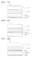
本発明の積層フィルムの第2の実施形態を、図2Aを適宜参照しながら説明する。なお、後述する変形例と区別するため、図2Aに示す実施形態を、特に、「基本形」という場合がある。先ず、本実施形態の積層フィルム201Aは、シーラントフィルム111と、バリアフィルム113と、カバーフィルム114とを含む。そして、本基本形のバリアフィルム113は、べースフィルム113aのシーラントフィルム111に対向する面とは反対側の面に第1の無機物バリア層113bを有する。また、本実施形態の積層フィルム201Aでは、シーラントフィルム111と、バリアフィルム113とは、直接もしくは有機溶剤を含まない無溶剤接着層を介して積層されている。換言すれば、シーラントフィルム111と、バリアフィルム113との間には、有機溶剤を含む接着剤及びアンカーコート剤のいずれも含まない。
<Second embodiment>
<< Basic form of the second embodiment >>
A second embodiment of the laminated film of the present invention will be described with reference to FIG. 2A as appropriate. The embodiment shown in FIG. 2A may be particularly referred to as a "basic form" in order to distinguish it from a modification described later. First, the laminated film 201A of the present embodiment includes the sealant film 111, the barrier film 113, and the cover film 114. The barrier film 113 of the present basic form has the first inorganic barrier layer 113b on the surface of the base film 113a opposite to the surface facing the sealant film 111. Further, in the laminated film 201A of the present embodiment, the sealant film 111 and the barrier film 113 are laminated directly or via a solvent-free adhesive layer containing no organic solvent. In other words, neither the adhesive containing an organic solvent nor the anchor coating agent is contained between the sealant film 111 and the barrier film 113.

(シーラントフィルム111)
上述した本発明の第1の実施形態の基本形のシーラントフィルム111と同様である。
(バリアフィルム113)
上述した本発明の第1の実施形態の基本形のバリアフィルム113と同様である。
(カバーフィルム114)
(Sealant film 111)
It is the same as the sealant film 111 of the basic form of the first embodiment of the present invention described above.
(Barrier film 113)
It is the same as the barrier film 113 of the basic form of the first embodiment of the present invention described above.
(Cover film 114)

本実施形態のカバーフィルム114は、上述したバリアフィルム113を保護するものである。また、カバーフィルム114は、熱可塑性樹脂からなるフィルムである。そして、カバーフィルム114に用いる熱可塑性樹脂としては、耐摩耗性、フィルム強度、突き刺し強度、透明性等の点から、ポリアミド樹脂又はポリエステル樹脂が好ましい。また、前記ポリアミド樹脂としては、ナイロン6、ナイロン66、ナイロン11、ナイロン12、MXDナイロン、共重合ナイロン等のナイロンが好ましい。また、前記ポリエステル樹脂としては、ポリエチレンテレフタレート(PET)、ポリエチレン−2,6−ナフタレート(PEN)等の芳香族ポリエステル樹脂が好ましい。さらに、カバーフィルム114としては、ポリアミド樹脂又はポリエステル樹脂を原料とする未延伸又は延伸したフィルムが好ましく、ナイロンフィルムがより好ましく、フィルム強度に優れることから、二軸延伸ナイロンフィルム(ONY)がさらに好ましい。カバーフィルム114の厚みは、7〜100μmが好ましい。 The cover film 114 of the present embodiment protects the barrier film 113 described above. Further, the cover film 114 is a film made of a thermoplastic resin. As the thermoplastic resin used for the cover film 114, a polyamide resin or a polyester resin is preferable from the viewpoints of wear resistance, film strength, piercing strength, transparency and the like. Further, as the polyamide resin, nylon such as nylon 6, nylon 66, nylon 11, nylon 12, MXD nylon, and copolymerized nylon is preferable. Further, as the polyester resin, aromatic polyester resins such as polyethylene terephthalate (PET) and polyethylene-2,6-naphthalate (PEN) are preferable. Further, as the cover film 114, an unstretched or stretched film made of a polyamide resin or a polyester resin is preferable, a nylon film is more preferable, and a biaxially stretched nylon film (ONY) is further preferable because the film strength is excellent. .. The thickness of the cover film 114 is preferably 7 to 100 μm.

そして、本実施形態の積層フィルム201Aは、第1の無機物バリア層113bがカバーフィルム114とべースフィルム113aとの間に存在するので、カバーフィルム114に紫外線吸収成分が含まれていたとしても、べースフィルム113a及びシーラントフィルム111に移行することがなく、試験液2に紫外線吸収成分が溶出することがない。 In the laminated film 201A of the present embodiment, since the first inorganic barrier layer 113b exists between the cover film 114 and the base film 113a, even if the cover film 114 contains an ultraviolet absorbing component, the base film It does not migrate to 113a and the sealant film 111, and the ultraviolet absorbing component does not elute into the test solution 2.

《第2の実施形態の第1変形例》 << First modification of the second embodiment >>

本発明の積層フィルムの第2の実施形態の第1変形例を、図2Bを適宜参照しながら説明する。本実施形態の積層フィルム201Bは、シーラントフィルム111と、バリアフィルム113と、カバーフィルム114とを含む。そして、本第1変形例のバリアフィルム113は、べースフィルム113aのシーラントフィルム111に対向する面に第2の無機物バリア層113cを有する。 A first modification of the second embodiment of the laminated film of the present invention will be described with reference to FIG. 2B as appropriate. The laminated film 201B of the present embodiment includes a sealant film 111, a barrier film 113, and a cover film 114. The barrier film 113 of the first modification has a second inorganic barrier layer 113c on the surface of the base film 113a facing the sealant film 111.

(シーラントフィルム111)
上述した本発明の第1の実施形態の基本形のシーラントフィルム111と同様である。
(バリアフィルム113)
上述した本発明の第1の実施形態の第1変形例のバリアフィルム113と同様である。
(カバーフィルム114)
上述した本発明の第2の実施形態の基本形のカバーフィルム114と同様である。
(Sealant film 111)
It is the same as the sealant film 111 of the basic form of the first embodiment of the present invention described above.
(Barrier film 113)
It is the same as the barrier film 113 of the first modification of the first embodiment of the present invention described above.
(Cover film 114)
It is the same as the cover film 114 of the basic form of the second embodiment of the present invention described above.

《第2の実施形態の第2変形例》
本発明の積層フィルムの第2の実施形態の第2変形例を、図2Cを適宜参照しながら説明する。本実施形態の積層フィルム201Cは、シーラントフィルム111と、バリアフィルム113と、カバーフィルム114とを含む。そして、本第2変形例のバリアフィルム113は、べースフィルム113aのシーラントフィルム111に対向する面とは反対側の面に第1の無機物バリア層113bを有し、シーラントフィルム111に対向する面に第2の無機物バリア層113cを有する。
<< Second variant of the second embodiment >>
A second modification of the second embodiment of the laminated film of the present invention will be described with reference to FIG. 2C as appropriate. The laminated film 201C of the present embodiment includes a sealant film 111, a barrier film 113, and a cover film 114. The barrier film 113 of the second modification has the first inorganic barrier layer 113b on the surface of the base film 113a opposite to the surface facing the sealant film 111, and is on the surface facing the sealant film 111. It has a second inorganic barrier layer 113c.

(シーラントフィルム111)
上述した本発明の第1の実施形態の基本形のシーラントフィルム111と同様である。
(バリアフィルム113)
上述した本発明の第1の実施形態の第2変形例のバリアフィルム113と同様である。
(カバーフィルム114)
上述した本発明の第2の実施形態の基本形のカバーフィルム114と同様である。
(Sealant film 111)
It is the same as the sealant film 111 of the basic form of the first embodiment of the present invention described above.
(Barrier film 113)
It is the same as the barrier film 113 of the second modification of the first embodiment of the present invention described above.
(Cover film 114)
It is the same as the cover film 114 of the basic form of the second embodiment of the present invention described above.

そして、本第2変形例の積層フィルム201Cは、バリアフィルム113が第1の無機物バリア層113bと第2の無機物バリア層113cとを備えることにより、より優れたガスバリア性能を発揮する。 The laminated film 201C of the second modification exhibits more excellent gas barrier performance because the barrier film 113 includes the first inorganic barrier layer 113b and the second inorganic barrier layer 113c.

〈第3の実施形態〉
《第3の実施形態の基本形》
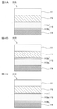
本発明の積層フィルムの第3の実施形態を、図3Aを適宜参照しながら説明する。なお、後述する変形例と区別するため、図3Aに示す実施形態を、特に、「基本形」という場合がある。本実施形態の積層フィルム301Aは、シーラントフィルム111と、プラスチックフィルム112と、バリアフィルム113とを含む。そして、本基本形のバリアフィルム113は、べースフィルム113aのシーラントフィルム111に対向する面とは反対側の面に第1の無機物バリア層113bを有する。また、本実施形態の積層フィルム301Aでは、シーラントフィルム111と、プラスチックフィルム112、プラスチックフィルム112とバリアフィルム113とは、それぞれ、直接もしくは有機溶剤を含まない無溶剤接着層を介して積層されている。換言すれば、シーラントフィルム111とプラスチックフィルム112との間、及びプラスチックフィルム112とバリアフィルム113との問には、有機溶剤を含む接着剤及びアンカーコート剤のいずれも含まない。
<Third embodiment>
<< Basic form of the third embodiment >>
A third embodiment of the laminated film of the present invention will be described with reference to FIG. 3A as appropriate. The embodiment shown in FIG. 3A may be particularly referred to as a "basic form" in order to distinguish it from a modification described later. The laminated film 301A of the present embodiment includes a sealant film 111, a plastic film 112, and a barrier film 113. The barrier film 113 of the present basic form has the first inorganic barrier layer 113b on the surface of the base film 113a opposite to the surface facing the sealant film 111. Further, in the laminated film 301A of the present embodiment, the sealant film 111 and the plastic film 112, the plastic film 112 and the barrier film 113 are laminated directly or via a solvent-free adhesive layer containing no organic solvent, respectively. .. In other words, the question between the sealant film 111 and the plastic film 112, and between the plastic film 112 and the barrier film 113, does not include any adhesive or anchor coating agent containing an organic solvent.

(シーラントフィルム111)
上述した本発明の第1の実施形態の基本形のシーラントフィルム111と同様である。
(Sealant film 111)
It is the same as the sealant film 111 of the basic form of the first embodiment of the present invention described above.

(プラスチックフィルム112)
シーラントフィルム111とバリアフィルム113との間にプラスチックフィルムを有すると、積層フィルム101のフィルム強度及び突き刺し強度を高めることができる。尚、プラスチックフィルム112は、熱可塑性樹脂からなるフィルムである。また、プラスチックフィルム112に用いる熱可塑性樹脂としては、例えば、上述した無添加ポリオレフィン、ポリアミド樹脂、ポリエステル樹脂、エチレン系ポリマーが挙げられる。また、前記ポリアミド樹脂としては、ナイロン6、ナイロン66、ナイロン11、ナイロン12、MXDナイロン、共重合ナイロン等が挙げられる。ナイロンフィルムとしては、フィルム強度に優れることから、二軸延伸ナイロンフィルム(ONY)を用いることが好ましい。また、前記ポリエステル樹脂としては、ポリエチレンテレフタレート(PET)が好ましい。また、前記エチレン系ポリマーとしては、エチレン−ビニルアルコール共重合体、エチレン−(メタ)アクリル酸共重合体、エチレン−(メタ)アクリル酸工ステル共重合体、エチレン−酢酸ビニル共重合体等が挙げられる。さらに、前記熱可塑性樹脂としては、紫外線吸収成分を含まないことから、無添加ポリオレフィンが好ましい。プラスチックフィルム112の厚みは、特に限定されないが7〜100μmが好ましい。そして、シーラントフィルム111とプラスチックフィルム112とは、有機溶剤を含む接着剤及びアンカーコート剤のいずれも用いず直接もしくは有機溶剤を含まない無溶剤接着層を介して積層されている。また、プラスチックフィルム112は、熱可塑性樹脂のフィルムの1枚からなるものであってもよいし、熱可塑性樹脂のフィルムの2枚以上を直接もしくは有機溶剤を含まない無溶剤接着層により積層したものであってもよい。この場合、熱可塑性樹脂のフィルムとフィルムの間には、有機溶剤を含む接着剤及びアンカーコート剤のいずれも含まない。
(Plastic film 112)
Having a plastic film between the sealant film 111 and the barrier film 113 can increase the film strength and the piercing strength of the laminated film 101. The plastic film 112 is a film made of a thermoplastic resin. Examples of the thermoplastic resin used for the plastic film 112 include the above-mentioned additive-free polyolefin, polyamide resin, polyester resin, and ethylene polymer. Examples of the polyamide resin include nylon 6, nylon 66, nylon 11, nylon 12, MXD nylon, and copolymerized nylon. As the nylon film, it is preferable to use a biaxially stretched nylon film (ONY) because of its excellent film strength. Further, as the polyester resin, polyethylene terephthalate (PET) is preferable. Examples of the ethylene polymer include ethylene-vinyl alcohol copolymer, ethylene- (meth) acrylic acid copolymer, ethylene- (meth) acrylic acid work steal copolymer, ethylene-vinyl acetate copolymer and the like. Can be mentioned. Further, as the thermoplastic resin, additive-free polyolefin is preferable because it does not contain an ultraviolet absorbing component. The thickness of the plastic film 112 is not particularly limited, but is preferably 7 to 100 μm. The sealant film 111 and the plastic film 112 are laminated directly or via a solvent-free adhesive layer that does not contain an organic solvent without using an adhesive containing an organic solvent or an anchor coating agent. Further, the plastic film 112 may be made of one film of a thermoplastic resin, or two or more films of a thermoplastic resin are directly laminated or laminated with a solvent-free adhesive layer containing no organic solvent. It may be. In this case, neither the adhesive containing an organic solvent nor the anchor coating agent is contained between the films of the thermoplastic resin.

(バリアフィルム113)
上述した本発明の第1の実施形態の基本形のバリアフィルム113と同様である。
(Barrier film 113)
It is the same as the barrier film 113 of the basic form of the first embodiment of the present invention described above.

《第3の実施形態の第1変形例》
本発明の積層フィルムの第3の実施形態の第1変形例を、図3Bを適宜参照しながら説明する。本実施形態の積層フィルム301Bは、シーラントフィルム111と、プラスチックフィルム112と、バリアフィルム113とを含む。そして、本第1変形例のバリアフィルム113は、べースフィルム113aのシーラントフィルム111に対向する面に第2の無機物バリア層113cを有する。
<< First modification of the third embodiment >>
A first modification of the third embodiment of the laminated film of the present invention will be described with reference to FIG. 3B as appropriate. The laminated film 301B of the present embodiment includes a sealant film 111, a plastic film 112, and a barrier film 113. The barrier film 113 of the first modification has a second inorganic barrier layer 113c on the surface of the base film 113a facing the sealant film 111.

(シーラントフィルム111)
上述した本発明の第1の実施形態の基本形のシーラントフィルム111と同様である。
(プラスチックフィルム112)
上述した本発明の第3の実施形態の基本形のプラスチックフィルム112と同様である。
(バリアフィルム113)
上述した本発明の第1の実施形態の第1変形例のバリアフィルム113と同様である。
(Sealant film 111)
It is the same as the sealant film 111 of the basic form of the first embodiment of the present invention described above.
(Plastic film 112)
It is the same as the plastic film 112 of the basic form of the third embodiment of the present invention described above.
(Barrier film 113)
It is the same as the barrier film 113 of the first modification of the first embodiment of the present invention described above.

《第3の実施形態の第2変形例》
本発明の積層フィルムの第3の実施形態の第2変形例を、図3Cを適宜参照しながら説明する。本実施形態の積層フィルム301Cは、シーラントフィルム111と、プラスチックフィルム112と、バリアフィルム113とを含む。そして、本第2変形例のバリアフィルム113は、べースフィルム113aのシーラントフィルム111に対向する面とは反対側の面に第1の無機物バリア層113bを有し、シーラントフィルム111に対向する面に第2の無機物バリア層113cを有する。
<< Second variant of the third embodiment >>
A second modification of the third embodiment of the laminated film of the present invention will be described with reference to FIG. 3C as appropriate. The laminated film 301C of the present embodiment includes a sealant film 111, a plastic film 112, and a barrier film 113. The barrier film 113 of the second modification has the first inorganic barrier layer 113b on the surface of the base film 113a opposite to the surface facing the sealant film 111, and is on the surface facing the sealant film 111. It has a second inorganic barrier layer 113c.

(シーラントフィルム111)
上述した本発明の第1の実施形態の基本形のシーラントフィルム111と同様である。
(プラスチックフィルム112)
上述した本発明の第3の実施形態の基本形のプラスチックフィルム112と同様である。
(バリアフィルム113)
上述した本発明の第1の実施形態の第2変形例のバリアフィルム113と同様である。
(Sealant film 111)
It is the same as the sealant film 111 of the basic form of the first embodiment of the present invention described above.
(Plastic film 112)
It is the same as the plastic film 112 of the basic form of the third embodiment of the present invention described above.
(Barrier film 113)
It is the same as the barrier film 113 of the second modification of the first embodiment of the present invention described above.

〈第4の実施形態〉
《第4の実施形態の基本形》
本発明の積層フィルムの第4の実施形態を、図4Aを適宜参照しながら説明する。なお、後述する変形例と区別するため、図4Aに示す実施形態を、特に、「基本形」という場合がある。本実施形態の積層フィルム401Aは、シーラントフィルム111と、プラスチックフィルム112と、バリアフィルム113と、カバーフィルム114とを含む。そして、本基本形のバリアフィルム113は、べースフィルム113aのシーラントフィルム111に対向する面とは反対側の面に第1の無機物バリア層113bを有する。また、本実施形態の積層フィルム401Aでは、シーラントフィルム111と、プラスチックフィルム112、プラスチックフィルム112とバリアフィルム113とは、それぞれ、直接もしくは有機溶剤を含まない無溶剤接着層を介して積層されている。換言すれば、シーラントフィルム111とプラスチックフィルム112との間、及びプラスチックフィルム112とバリアフィルム113との間には、有機溶剤を含む接着剤及びアンカーコート剤のいずれも含まない。
<Fourth Embodiment>
<< Basic form of the fourth embodiment >>
A fourth embodiment of the laminated film of the present invention will be described with reference to FIG. 4A as appropriate. The embodiment shown in FIG. 4A may be particularly referred to as a "basic form" in order to distinguish it from a modification described later. The laminated film 401A of the present embodiment includes a sealant film 111, a plastic film 112, a barrier film 113, and a cover film 114. The barrier film 113 of the present basic form has the first inorganic barrier layer 113b on the surface of the base film 113a opposite to the surface facing the sealant film 111. Further, in the laminated film 401A of the present embodiment, the sealant film 111, the plastic film 112, the plastic film 112 and the barrier film 113 are laminated directly or via a solvent-free adhesive layer containing no organic solvent, respectively. .. In other words, neither the adhesive containing an organic solvent nor the anchor coating agent is contained between the sealant film 111 and the plastic film 112, and between the plastic film 112 and the barrier film 113.

(シーラントフィルム111)
上述した本発明の第1の実施形態の基本形のシーラントフィルム111と同様である。
(プラスチックフィルム112)
上述した本発明の第3の実施形態の基本形のプラスチックフィルム112と同様である。
(バリアフィルム113)
上述した本発明の第3の実施形態の基本形のバリアフィルム113と同様である。
(カバーフィルム114)
上述した本発明の第2の実施形態の基本形のカバーフィルム114と同様である。
(Sealant film 111)
It is the same as the sealant film 111 of the basic form of the first embodiment of the present invention described above.
(Plastic film 112)
It is the same as the plastic film 112 of the basic form of the third embodiment of the present invention described above.
(Barrier film 113)
It is the same as the barrier film 113 of the basic form of the third embodiment of the present invention described above.
(Cover film 114)
It is the same as the cover film 114 of the basic form of the second embodiment of the present invention described above.

《第4の実施形態の第1変形例》
本発明の積層フィルムの第4の実施形態の第1変形例を、図4Bを適宜参照しながら説明する。本実施形態の積層フィルム401Bは、シーラントフィルム111と、プラスチックフィルム112と、バリアフィルム113と、カバーフィルム114とを含む。そして、本第1変形例のバリアフィルム113は、べースフィルム113aのシーラントフィルム111に対向する面に第2の無機物バリア層113cを有する。
<< First modification of the fourth embodiment >>
A first modification of the fourth embodiment of the laminated film of the present invention will be described with reference to FIG. 4B as appropriate. The laminated film 401B of the present embodiment includes a sealant film 111, a plastic film 112, a barrier film 113, and a cover film 114. The barrier film 113 of the first modification has a second inorganic barrier layer 113c on the surface of the base film 113a facing the sealant film 111.

(シーラントフィルム111)
上述した本発明の第1の実施形態の基本形のシーラントフィルム111と同様である。
(プラスチックフィルム112)
上述した本発明の第3の実施形態の基本形のプラスチックフィルム112と同様である。
(バリアフィルム113)
上述した本発明の第3の実施形態の第1変形例のバリアフィルム113と同様である。
(カバーフィルム114)
上述した本発明の第2の実施形態の第1変形例のカバーフィルム114と同様である。
(Sealant film 111)
It is the same as the sealant film 111 of the basic form of the first embodiment of the present invention described above.
(Plastic film 112)
It is the same as the plastic film 112 of the basic form of the third embodiment of the present invention described above.
(Barrier film 113)
It is the same as the barrier film 113 of the first modification of the third embodiment of the present invention described above.
(Cover film 114)
It is the same as the cover film 114 of the first modification of the second embodiment of the present invention described above.

《第4の実施形態の第2変形例》
本発明の積層フィルムの第4の実施形態の第2変形例を、図4Cを適宜参照しながら説明する。本実施形態の積層フィルム401Cは、シーラントフィルム111と、プラスチックフィルム112と、バリアフィルム113と、カバーフィルム114とを含む。そして、本第2変形例のバリアフィルム113は、べースフィルム113aのシーラントフィルム111に対向する面とは反対側の面に第1の無機物バリア層113bを有し、シーラントフィルム111に対向する面に第2の無機物バリア層113cを有する。
<< Second variant of the fourth embodiment >>
A second modification of the fourth embodiment of the laminated film of the present invention will be described with reference to FIG. 4C as appropriate. The laminated film 401C of the present embodiment includes a sealant film 111, a plastic film 112, a barrier film 113, and a cover film 114. The barrier film 113 of the second modification has the first inorganic barrier layer 113b on the surface of the base film 113a opposite to the surface facing the sealant film 111, and is on the surface facing the sealant film 111. It has a second inorganic barrier layer 113c.

(シーラントフィルム111)
上述した本発明の第3の実施形態の基本形のシーラントフィルム111と同様である。
(プラスチックフィルム112)
上述した本発明の第3の実施形態の基本形のプラスチックフィルム112と同様である。
(バリアフィルム113)
上述した本発明の第3の実施形態の第2変形例のバリアフィルム113と同様である。
(カバーフィルム114)
上述した本発明の第2の実施形態の第2変形例のカバーフィルム114と同様である。
(Sealant film 111)
It is the same as the sealant film 111 of the basic form of the third embodiment of the present invention described above.
(Plastic film 112)
It is the same as the plastic film 112 of the basic form of the third embodiment of the present invention described above.
(Barrier film 113)
It is the same as the barrier film 113 of the second modification of the third embodiment of the present invention described above.
(Cover film 114)
It is the same as the cover film 114 of the second modification of the second embodiment of the present invention described above.

尚、好ましい構成の積層フィルムとして、ONY/酸化ケイ素蒸着PETフィルム/無添加LDPE/無添加LDPE、ONY/酸化ケイ素蒸着PETフィルム/無添加LDPE/無添加LLDPE、ONY/酸化ケイ素蒸着PETフィルム/EMAA(エチレン−アクリル酸共重合体)/無添加LLDPE等の四層積層フィルムが挙げられる。
〈製造方法〉
As the laminated film having a preferable configuration, ONY / silicon oxide vapor-deposited PET film / additive-free LDPE / additive-free LDPE, ONY / silicon oxide vapor-deposited PET film / additive-free LDPE / additive-free LLDPE, ONY / silicon oxide vapor-deposited PET film / EMAA Examples thereof include a four-layer laminated film such as (ethylene-acrylic acid copolymer) / additive-free LLDPE.
<Production method>

本発明の第1〜第4の実施形態の積層フィルム101A〜401Cは、シーラントフィルム111とバリアフィルム113、シーラントフィルム111とバリアフィルム113とカバーフィルム114、シーラントフィルム111とプラスチックフィルム112とバリアフィルム113、シーラントフィルム111とプラスチックフィルム112とバリアフィルム113とカバーフィルム114とを、所定の層構成となるように積層することにより製造できる。カバーフィルム114とバリアフィルム113との積層方法は、特に限定されず、接着剤を用いたドライラミネート法、熱接着性樹脂等を用いた押出ラミネート法等の公知の方法を使用することができる。また、ドライラミネート法で使用する接着剤としては、ポリウレタン系接着剤、ポリエステル系接着剤、アクリル系接着剤等が好ましい。ドライラミネート法の中でも、溶出の問題が生じにくい、接着強度に優れる等の点から、ポリウレタン系接着剤を用いたドライラミネート法が好ましい。特に、耐酸性に優れ、積層フィルムからの溶出成分が少なくなることから、ポリオール成分としてポリエステル系ポリオールを用いたポリウレタン系接着剤(以下、ポリエステル系ポリウレタン接着剤)が好ましい。 The laminated films 101A to 401C of the first to fourth embodiments of the present invention include the sealant film 111 and the barrier film 113, the sealant film 111 and the barrier film 113 and the cover film 114, and the sealant film 111 and the plastic film 112 and the barrier film 113. , The sealant film 111, the plastic film 112, the barrier film 113, and the cover film 114 can be manufactured by laminating them so as to have a predetermined layer structure. The laminating method of the cover film 114 and the barrier film 113 is not particularly limited, and known methods such as a dry laminating method using an adhesive and an extrusion laminating method using a heat-adhesive resin can be used. Further, as the adhesive used in the dry laminating method, a polyurethane-based adhesive, a polyester-based adhesive, an acrylic-based adhesive or the like is preferable. Among the dry laminating methods, the dry laminating method using a polyurethane adhesive is preferable from the viewpoints that the problem of elution does not easily occur and the adhesive strength is excellent. In particular, a polyurethane-based adhesive using a polyester-based polyol as a polyol component (hereinafter referred to as a polyester-based polyurethane adhesive) is preferable because it has excellent acid resistance and the amount of elution components from the laminated film is reduced.

また、シーラントフィルム111とバリアフィルム113との積層方法、バリアフィルム113とプラスチックフィルム112との積層方法、プラスチックフィルム112とシーラントフィルム111との積層方法は、有機溶剤を含む接着剤及びAC剤(アンカーコート剤)のいずれも使用せず、直接積層する方法では、例えば、熱接着性樹脂等を用いAC剤を使用しない押出ラミネート法、サーマルラミネート法を用いることができる。また、有機溶剤を含まない無溶剤接着層により接着する方法では、有機溶剤を用いない脂肪族エステル系接着剤、芳香族エーテル系接着剤、その他水溶性またはエマルジョンタイプの接着剤を用いたノンソルベントラミネート法、ウェットラミネート法等を用いることができる。 Further, the laminating method of the sealant film 111 and the barrier film 113, the laminating method of the barrier film 113 and the plastic film 112, and the laminating method of the plastic film 112 and the sealant film 111 are an adhesive containing an organic solvent and an AC agent (anchor). As a method of directly laminating without using any of the coating agent), for example, an extrusion laminating method or a thermal laminating method using a heat-adhesive resin or the like and not using an AC agent can be used. In the method of adhering with a solvent-free adhesive layer that does not contain an organic solvent, a non-solvent using an aliphatic ester adhesive that does not use an organic solvent, an aromatic ether adhesive, or another water-soluble or emulsion type adhesive is used. A laminating method, a wet laminating method, or the like can be used.

尚、上記の各フィルムを接着する場合、フィルムに表面処理を施しておくことが好ましい。前記表面処理としては、コロナ放電処理、プラズマ処理、電子線・放射線処理等が挙げられる。 When adhering each of the above films, it is preferable to apply a surface treatment to the films. Examples of the surface treatment include corona discharge treatment, plasma treatment, electron beam / radiation treatment, and the like.

そして、本発明の試験液製品1に好適な容器は、前記試験液2を収容する袋状の容器本体3を備え、前記容器本体3が、上述した積層フィルム101A〜401Cから構成される。 A container suitable for the test liquid product 1 of the present invention includes a bag-shaped container body 3 for accommodating the test liquid 2, and the container body 3 is composed of the above-mentioned laminated films 101A to 401C.

次に、実施例により本発明をより具体的に説明する。ただし、本発明は、後述する実施例に限定されるものではなく、発明の要旨を逸脱しない限り、種々の変形が可能である。
(溶出試験)
[試験液の準備]
Next, the present invention will be described more specifically by way of examples. However, the present invention is not limited to the examples described later, and various modifications can be made as long as the gist of the invention is not deviated.
(Elution test)
[Preparation of test solution]

以下の試験液2を準備した。
試験液A:日本薬局方精製水(共栄製薬社製)
試験液B:崩壊試験第1液、pH1.2/溶出試験第1液、pH1.2(関東化学社製)
The following test solution 2 was prepared.
Test solution A: Japanese Pharmacopoeia purified water (manufactured by Kyoei Pharmaceutical Co., Ltd.)
Test solution B: Disintegration test 1st solution, pH1.2 / Elution test 1st solution, pH1.2 (manufactured by Kanto Chemical Co., Inc.)

<ONY15μm/ドライ/蒸着PET12μm/押出LDPE(無添加)20μm/LDPE(無添加)100μm/試験液A、B>
ONY(ユニチカ社製、エンブレムON、厚み15μm)と、無機酸化物蒸着フィルム、テックバリアHX(三菱ケミカル社製、厚み12μm)を、ポリエステル系ポリウレタン接着剤(東洋モートン社製、トモフレックスTM−250)を用いてドライラミネート法で貼り合わせ、さらにAC剤を用いずにLDPE(東ソー社製、ペトロセンDLZ10A、20μm)を用いて無添加LDPEフィルム(タマポリ社製、SK615P、100μm)を押出ラミネート法により貼り合わせ、積層フィルム201Bを得た。この積層フィルムを用いて図5に示すような形態の容器を作製し、試験液A、Bを充填して試験液製品1を製造した。そして、製造した試験液製品1について、後述する評価方法によって評価を行った。
<ONY 15 μm / Dry / Evaporated PET 12 μm / Extruded LDPE (additive-free) 20 μm / LDPE (additive-free) 100 μm / Test solutions A and B>
ONY (Unitika, emblem ON, thickness 15 μm), inorganic oxide vapor-deposited film, Tech Barrier HX (Mitsubishi Chemical, thickness 12 μm), polyester polyurethane adhesive (Toyo Morton, Tomoflex TM-250) ) Is laminated by the dry laminating method, and an additive-free LDPE film (manufactured by Tamapoli, SK615P, 100 μm) is extruded using LDPE (Tosoh, Petrosen DLZ10A, 20 μm) without using an AC agent. The laminated film 201B was obtained by laminating. Using this laminated film, a container having the shape shown in FIG. 5 was prepared, and the test liquids A and B were filled to manufacture the test liquid product 1. Then, the manufactured test liquid product 1 was evaluated by an evaluation method described later.

<ONY15μm/ドライ/蒸着PET12μm/押出LDPE(無添加)20μm/LLDPE(無添加)100μm/試験液A、B>
ONY(ユニチカ社製、エンブレムON、厚み15μm)と、無機酸化物蒸着フィルム、テックバリアHX(三菱ケミカル社製、厚み12μm)を、ポリエステル系ポリウレタン接着剤(東洋モートン社製、トモフレックスTM−250)を用いてドライラミネート法で貼り合わせ、さらにAC剤を用いずにLDPE(東ソー社製、ペトロセンDLZ10A、20μm)を用いて無添加LLDPEフィルム(タマポリ社製、SF625P、100μm)を押出ラミネート法により貼り合わせ、積層フィルム201Bを得た。この積層フィルムを用いて図5に示すような形態の容器を作製し、試験液A、Bを充填して試験液製品1を製造した。そして、製造した試験液製品1について、後述する評価方法によって評価を行った。
<ONY 15 μm / Dry / Evaporated PET 12 μm / Extruded LDPE (additive-free) 20 μm / LLDPE (additive-free) 100 μm / Test solutions A and B>
ONY (Unitika, emblem ON, thickness 15 μm), inorganic oxide vapor-deposited film, Tech Barrier HX (Mitsubishi Chemical, thickness 12 μm), polyester polyurethane adhesive (Toyo Morton, Tomoflex TM-250) ) Is laminated by the dry laminating method, and an additive-free LLDPE film (manufactured by Tamapoli, SF625P, 100 μm) is extruded using LDPE (Tosoh, Petrosen DLZ10A, 20 μm) without using an AC agent. The laminated film 201B was obtained by laminating. Using this laminated film, a container having the shape shown in FIG. 5 was prepared, and the test liquids A and B were filled to manufacture the test liquid product 1. Then, the manufactured test liquid product 1 was evaluated by an evaluation method described later.

<ONY25μm/ドライ/透明VMPET12μm/押出EMAA20μm/LLDPE100μm(無添加)/試験液A、B>
ONY(ユニチカ社製、エンブレムON、厚み15μm)と、透明バリアフィルムVMPETクラリスタCI(クラレ社製、厚み12μm)を、ポリエステル系ポリウレタン接着剤(東洋モートン社製、トモフレックスTM−250)を用いてドライラミネート法で貼り合わせ、さらにAC剤を用いずにEMAA(エチレン−メタクリル酸共重合体、三井・ダウポリケミカル社製、ニュクレルN1108C、20μm)を用いて無添加LLDPEフィルム(タマポリ社製、SK615P、100μm)を押出ラミネート法により貼り合わせ、積層フィルム201Bを得た。この積層フィルムを用いて図5に示すような形態の容器を作製し、試験液A、Bを充填して試験液製品1を製造した。そして、製造した試験液製品1について、後述する評価方法によって評価を行った。
<ONY 25 μm / Dry / Transparent VMPET 12 μm / Extruded EMAA 20 μm / LLDPE 100 μm (no additives) / Test solutions A and B>
ONY (Unitika, emblem ON, thickness 15 μm) and transparent barrier film VMPET Clarista CI (Kurare, thickness 12 μm) using polyester-based polyurethane adhesive (Toyo Morton, Tomoflex TM-250) Additive-free LLDPE film (manufactured by Tamapoli, SK615P) using EMAA (ethylene-methacrylic acid copolymer, Nuclel N1108C, 20 μm) manufactured by Mitsui-Dau Polychemical Co., Ltd. , 100 μm) was laminated by an extrusion laminating method to obtain a laminated film 201B. Using this laminated film, a container having the shape shown in FIG. 5 was prepared, and the test liquids A and B were filled to manufacture the test liquid product 1. Then, the manufactured test liquid product 1 was evaluated by an evaluation method described later.

[比較例1]
<ONY15μm/ドライ/蒸着PET12μm/AC/押出LLDPE100μm/試験液A、B>
ONY(ユニチカ社製、エンブレムON、厚み15μm)と、無機酸化物蒸着フィルムテックバリアHX(三菱ケミカル社製、厚み12μm)とを、ポリエステル系ポリウレタン接着剤(東洋モートン社製、トモフレックスTM−250)を用いてドライラミネート法で貼り合わせ、さらに押出ラミネート用AC剤(東洋モートン社製、EL−510)を用いてLLDPE(プライムポリマー社製、ウルトラゼックス100μm)の押し出し層を形成し、積層フィルムを得た。この積層フィルムを用いて図5に示すような形態の容器を作製し、試験液A、Bを充填して試験液製品1を製造した。そして、製造した試験液製品1について、後述する評価方法によって評価を行った。
[Comparative Example 1]
<ONY 15 μm / Dry / Evaporated PET 12 μm / AC / Extruded LLDPE 100 μm / Test liquids A and B>
ONY (Unitika, emblem ON, thickness 15 μm) and inorganic oxide vapor deposition film Tech Barrier HX (Mitsubishi Chemical, thickness 12 μm) are combined with a polyester polyurethane adhesive (Toyo Morton, Tomoflex TM-250). ) Is used for laminating by the dry laminating method, and then an extruded layer of LLDPE (Prime Polymer Co., Ltd., Ultra Zex 100 μm) is formed using an AC agent for extrusion laminating (manufactured by Toyo Morton Co., Ltd., EL-510) to form a laminated film. Got Using this laminated film, a container having the shape shown in FIG. 5 was prepared, and the test liquids A and B were filled to manufacture the test liquid product 1. Then, the manufactured test liquid product 1 was evaluated by an evaluation method described later.

[比較例2]
<PET16μm/ドライ/ONY25μm/ドライ/蒸着PET12μm/AC/押出LLDPE100μm/試験液A、B>
二軸延伸PETフィルム(ユニチカ社製、エンブレットPET、厚み16μm)と、ONY(ユニチカ社製、エンブレムON、厚み25μm)と、無機酸化物蒸着フィルムテックバリアHX(三菱ケミカル社製、厚み12μm)とを、ポリエステル系ポリウレタン接着剤(東洋モートン社製、トモフレックスTM−250)を用いてドライラミネート法で貼り合わせ、さらに押出ラミネート用AC剤(東洋モートン社製、EL−510)を用いてLLDPE(プライムポリマー社製、ウルトラゼックス100μm)押し出し層を形成し、積層フィルムを得た。この積層フィルムを用いて図5に示すような形態の容器を作製し、試験液A、Bを充填して試験液製品1を製造した。そして、製造した試験液製品1について、後述する評価方法によって評価を行った。
[Comparative Example 2]
<PET 16 μm / Dry / ONY 25 μm / Dry / Evaporated PET 12 μm / AC / Extruded LLDPE 100 μm / Test liquids A and B>
Biaxially stretched PET film (manufactured by Unitika, emblem PET, thickness 16 μm), ONY (manufactured by Unitika, emblem ON, thickness 25 μm), and inorganic oxide vapor deposition film Tech Barrier HX (manufactured by Mitsubishi Chemical Co., thickness 12 μm) And LLDPE are laminated by a dry laminating method using a polyester-based polyurethane adhesive (Toyo Morton Co., Ltd., Tomoflex TM-250), and further using an AC agent for extrusion laminating (Toyo Morton Co., Ltd., EL-510). (Ultra Zex 100 μm manufactured by Prime Polymer Co., Ltd.) An extruded layer was formed to obtain a laminated film. Using this laminated film, a container having the shape shown in FIG. 5 was prepared, and the test liquids A and B were filled to manufacture the test liquid product 1. Then, the manufactured test liquid product 1 was evaluated by an evaluation method described later.

[比較例3]
<ONY15μm/AC/押出/LLDPE70μm/試験液A、B>
上記構成の市販のスタンド袋(カウパック社製、TP−S0350)に試験液A、Bを充填して試験液製品1を製造した。そして、後述する評価方法によって評価を行った。
[Comparative Example 3]
<ONY 15 μm / AC / Extrusion / LLDPE 70 μm / Test liquids A and B>
The test liquid product 1 was manufactured by filling the commercially available stand bag (manufactured by Cowpack, TP-S0350) having the above configuration with the test liquids A and B. Then, the evaluation was performed by the evaluation method described later.

[比較例4]
<PET12μm/ドライ/蒸着PET12μm/ドライ/ONY15μm/ドライ/LLDPE130μm/試験液A、B>
上記で構成の市販の2ピースキャップ付きスタンド袋(カウパック社製、DP16−TW0400)に試験液A、Bを充填して試験液製品1を製造した。そして、後述する評価方法によって評価を行った。
[Comparative Example 4]
<PET 12 μm / Dry / Evaporated PET 12 μm / Dry / ONY 15 μm / Dry / LLDPE 130 μm / Test solutions A and B>
The test liquid product 1 was manufactured by filling the commercially available stand bag with a two-piece cap (manufactured by Cowpack, DP16-TW0400) having the above configuration with the test liquids A and B. Then, the evaluation was performed by the evaluation method described later.

[比較例5]
<蒸着PET12μm/ドライ/PET12μm/ドライ/ONY15μm/ドライ/LLDPE130μm/試験液A、B>
無機酸化物蒸着フィルム(テックバリアHX、三菱ケミカル社製、厚み12μm)と、二軸延伸PETフィルム(ユニチカ社製、エンブレットPET、厚み12μm)と、ONY(ユニチカ社製、エンブレムON、厚み15μm)と、LLDPEフィルム(タマポリ社製、UB106、厚み130μm)とを、ポリエステル系ポリウレタン接着剤(東洋モートン社製、トモフレックスTM−250)を用いてドライラミネート法で貼り合わせて積層フィルムを得た。この積層フィルムを用いて図5に示すような形態の容器を作製し、試験液A、Bを充填して試験液製品1を製造した。そして、製造した試験液製品1について、後述する評価方法によって評価を行った。
[Comparative Example 5]
<Evaporation PET 12 μm / Dry / PET 12 μm / Dry / ONY 15 μm / Dry / LLDPE 130 μm / Test solutions A and B>
Inorganic oxide vapor-deposited film (Tech Barrier HX, manufactured by Mitsubishi Chemical Co., Ltd., thickness 12 μm), biaxially stretched PET film (manufactured by Unitika Ltd., emblem PET, thickness 12 μm), and ONY (manufactured by Unitika Ltd., emblem ON, thickness 15 μm). ) And an LLDPE film (manufactured by Tamapoli, UB106, thickness 130 μm) were bonded together by a dry laminating method using a polyester-based polyurethane adhesive (manufactured by Toyo Morton, Tomoflex TM-250) to obtain a laminated film. .. Using this laminated film, a container having the shape shown in FIG. 5 was prepared, and the test liquids A and B were filled to manufacture the test liquid product 1. Then, the manufactured test liquid product 1 was evaluated by an evaluation method described later.

[評価方法]
実施例1〜3、比較例1〜5で得られた試験液製品1について、以下の評価を行った。
[Evaluation method]
The test liquid products 1 obtained in Examples 1 to 3 and Comparative Examples 1 to 5 were evaluated as follows.

(保管による紫外線吸収性溶出物の多寡)
各例の試験液製品1を、40℃で60日間保管した。その後、各試験液製品1から試験液A、Bを抜き出し、UV吸収測定装置(日立分光光度計、U−3000)を用いて、波長220nm及び250nmにおける吸光度を測定し、紫外線吸収性溶出物の溶出量の指標とした。
(The amount of UV-absorbing eluate from storage)
The test solution product 1 of each example was stored at 40 ° C. for 60 days. Then, the test solutions A and B were extracted from each test solution product 1, and the absorbance at wavelengths of 220 nm and 250 nm was measured using a UV absorption measuring device (Hitachi spectrophotometer, U-3000) to measure the absorbance of the ultraviolet absorbing eluate. It was used as an index of the amount of elution.

結果を表1及び表2の「吸光度」の欄に示す。その結果、試験液製品1を構成するシーラントフィルム111に無添加ポリオレフィンを使用し、シーラントフィルム及びバリアフィルムを、AC剤及び接着剤のいずれも使用せず、直接積層した実施例1、2、3については、保存後の試験液A、Bに紫外部吸収が認められなかった。 The results are shown in the "Asorbance" column of Tables 1 and 2. As a result, Examples 1, 2, and 3 in which additive-free polyolefin was used for the sealant film 111 constituting the test liquid product 1 and the sealant film and the barrier film were directly laminated without using any AC agent or adhesive. No ultraviolet absorption was observed in the test solutions A and B after storage.

(保管時の質量減少量)
各例の試験液製品1を40℃で60日間保管した。保管前後の各試験液製品1の質量を測定し、1袋1日当たりの減量を算出した。結果を表1及び表2の「減少質量」の欄に示す。

Figure 2021181985
Figure 2021181985
(Amount of mass loss during storage)
The test solution product 1 of each example was stored at 40 ° C. for 60 days. The mass of each test solution product 1 before and after storage was measured, and the weight loss per bag per day was calculated. The results are shown in the "Reduced mass" column of Tables 1 and 2.
Figure 2021181985
Figure 2021181985

[結果の説明]
(保管による紫外線吸収性溶出物の多寡)
試験液製品1を構成するシーラントフィルム111に無添加ポリオレフィンを使用し、シーラントフィルム及びバリアフィルムを、AC剤及び接着剤のいずれも使用せず、直接積層した実施例1〜3の試験液製品1では、保存後の試験液2に紫外部吸収がほとんど認めなかった。
[Explanation of results]
(The amount of UV-absorbing eluate from storage)
Test liquid products 1 of Examples 1 to 3 in which additive-free polyolefin was used for the sealant film 111 constituting the test liquid product 1 and the sealant film and the barrier film were directly laminated without using any AC agent or adhesive. Then, almost no ultraviolet absorption was observed in the test solution 2 after storage.

(保管時の質量減少量)
無機酸化物を蒸着したバリアフィルム(蒸着PET12μ)を含む積層フィルムを用いて構成した実施例1〜3、比較例1、2、4及び5の試験液製品1の質量減少は極めて小さく、十分な水蒸気透過バリア性が認められた。
(脱気試験)
(Amount of mass loss during storage)
The mass loss of the test liquid products 1 of Examples 1 to 3 and Comparative Examples 1, 2, 4 and 5 configured by using a laminated film containing a barrier film (evaporated PET 12μ) on which an inorganic oxide was vapor-deposited is extremely small and sufficient. A water vapor permeation barrier was observed.
(Deaeration test)

濃塩酸(関東化学製試薬特級)70mLおよび塩化ナトリウム(和光純薬製、試薬特級)20.0gを正確に計り、日局精製水(共栄製薬製)に溶解して全量を正確に10Lとし試験液2を得た。次に、中空糸膜を用いた脱気モジュールを用いて試験液2に対する脱気を行った。この試験液2の脱気度は溶存酸素濃度として3.2mg/Lであった。また、ナイロンフィルム(べースフィルム113a)とアルミ箔(第2の無機物バリア層113c)と無添加低密度ポリエチレンフィルム(シーラントフィルム111)とが積層したフィルムからなるラミネート袋を準備した。そして、得られた試験液2の900mLを、900mL容量のメスフラスコに正確に分取し、上記のラミネート袋の上部開口から充填した。その後、脱気シーラーで容器内の空気を抜いた後、ラミネート袋の上部開口をヒートシールして密閉し、試験液製品1を得た。残りの試験液2についても同様の操作(分取、ラミネート袋への充填、密封)を行い、溶出試験第一液900mLが正確に分包された試験液製品1を11個を得た。尚、試験液製品1のヘッドスペース30は試験液2の容積(900mL)の1%以下であった。 Accurately measure 70 mL of concentrated hydrochloric acid (Kanto Chemical's special grade reagent) and 20.0 g of sodium chloride (Wako Pure Chemical Industries, Ltd., special reagent grade) and dissolve in purified water from Japan Bureau (manufactured by Kyoei Pharmaceutical Co., Ltd.) to make the total amount exactly 10 L. Liquid 2 was obtained. Next, the test liquid 2 was degassed using a degassing module using a hollow fiber membrane. The degree of degassing of this test solution 2 was 3.2 mg / L as the dissolved oxygen concentration. Further, a laminated bag made of a film in which a nylon film (base film 113a), an aluminum foil (second inorganic barrier layer 113c) and an additive-free low-density polyethylene film (sealant film 111) are laminated was prepared. Then, 900 mL of the obtained test solution 2 was accurately dispensed into a 900 mL volumetric flask and filled from the upper opening of the above-mentioned laminate bag. Then, after removing the air in the container with a degassing sealer, the upper opening of the laminated bag was heat-sealed and sealed to obtain a test liquid product 1. The same operation (preparation, filling in a laminating bag, sealing) was performed on the remaining test liquid 2, and 11 test liquid products 1 in which 900 mL of the first elution test liquid was accurately packaged were obtained. The head space 30 of the test liquid product 1 was 1% or less of the volume (900 mL) of the test liquid 2.

リン酸二水素一カリウム(関東化学製試薬特級)17.0gおよびリン酸一水素二ナトリウム(関東化学製試薬特級)17.75gを正確に計り、日局精製水(共栄製薬製)に溶解して全量を正確に10Lとし試験液2を得た。次に、中空糸膜を用いた脱気モジュールを用いて試験液2に対する脱気を行った。この試験液2の脱気度は[実施例1]と同等であった。また、ポリエチレンテレフタレートフィルム(べースフィルム113a)とアルミ箔とナイロンフィルム(第2の無機物バリア層113c)と無添加ポリプロピレンフィルム(シーラントフィルム111)とがこの順に積層したフィルムからなるラミネート袋を準備した。そして、得られた試験液2の900mLを、900mL容量のメスフラスコに正確に分取し、上記のラミネート袋の上部開口から充填した。その後、脱気シーラーで容器内の空気を抜いた後、ラミネート袋の上部開口をヒートシールして密閉し、試験液製品1を得た。残りの試験液2についても同様の操作(分取、ラミネート袋への充填、密封)を行い、溶出試験第二液(pH6.8のうすめたリン酸緩衝液)900mLが正確に分包された試験液製品1を11個を得た。尚、試験液製品1のヘッドスペース30は試験液2の容積(900mL)の1%以下であった。 Accurately weigh 17.0 g of monopotassium dihydrogen phosphate (special grade reagent manufactured by Kanto Chemical Co., Inc.) and 17.75 g of disodium monohydrogen phosphate (special grade reagent manufactured by Kanto Chemical Co., Inc.) and dissolve in purified water from Japan Bureau (Kyoei Pharmaceutical Co., Ltd.). The total amount was exactly 10 L, and the test solution 2 was obtained. Next, the test liquid 2 was degassed using a degassing module using a hollow fiber membrane. The degree of degassing of this test solution 2 was the same as that of [Example 1]. Further, a laminated bag was prepared in which a polyethylene terephthalate film (base film 113a), an aluminum foil, a nylon film (second inorganic barrier layer 113c), and an additive-free polypropylene film (sealant film 111) were laminated in this order. Then, 900 mL of the obtained test solution 2 was accurately dispensed into a 900 mL volumetric flask and filled from the upper opening of the above-mentioned laminate bag. Then, after removing the air in the container with a degassing sealer, the upper opening of the laminated bag was heat-sealed and sealed to obtain a test liquid product 1. The same operation (preparation, filling in a laminate bag, sealing) was performed for the remaining test solution 2, and 900 mL of the second elution test solution (diluted phosphate buffer solution having a pH of 6.8) was accurately packaged. Eleven test solution products 1 were obtained. The head space 30 of the test liquid product 1 was 1% or less of the volume (900 mL) of the test liquid 2.

無水リン酸水素二ナトリウム71.0gを(和光純薬製、試薬特級)、日局精製水(共栄製薬製)に溶かし10Lとした。この液に、クエン酸一水和物(純正薬品製、試薬特級)53gを日局精製水(共栄製薬製)に溶かして10Lとした液を加えてpH8.0に調整し試験液2を得た。次に、中空糸膜を用いた脱気モジュールを用いて試験液2に対する脱気を行った。この試験液2の脱気度は[実施例1]と同等であった。また、ポリエチレンテレフタレートフィルム(べースフィルム113a)とアルミ箔とナイロンフィルム(第2の無機物バリア層113c)と無添加ポリプロピレンフィルム(シーラントフィルム111)とがこの順に積層したフィルムからなるラミネート袋を準備した。そして、得られた試験液2の900mLを、900mL容量のメスフラスコに正確に分取し、上記のラミネート袋の上部開口から充填した。その後、脱気シーラーで容器内の空気を抜いた後、ラミネート袋の上部開口をヒートシールして密閉し、試験液製品1を得た。残りの試験液2についても同様の操作(分取、ラミネート袋への充填、密封)を行い、pH8.0 リン酸水素二Na・クエン酸緩衝液900mLが正確に分包された試験液製品1を12個を得た。尚、試験液製品1のヘッドスペース30は試験液2の容積(900mL)の1%以下であった。 71.0 g of anhydrous disodium hydrogen phosphate (manufactured by Wako Pure Chemical Industries, Ltd., special grade reagent) was dissolved in Japanese Pharmacopoeia purified water (manufactured by Kyoei Pharmaceutical Co., Ltd.) to make 10 L. To this solution, 53 g of citric acid monohydrate (manufactured by genuine chemicals, special grade reagent) was dissolved in purified water of Japan Pharmacopoeia (manufactured by Kyoei Pharmaceutical Co., Ltd.) to make 10 L, and the pH was adjusted to 8.0 to obtain test solution 2. rice field. Next, the test liquid 2 was degassed using a degassing module using a hollow fiber membrane. The degree of degassing of this test solution 2 was the same as that of [Example 1]. Further, a laminated bag was prepared in which a polyethylene terephthalate film (base film 113a), an aluminum foil, a nylon film (second inorganic barrier layer 113c), and an additive-free polypropylene film (sealant film 111) were laminated in this order. Then, 900 mL of the obtained test solution 2 was accurately dispensed into a 900 mL volumetric flask and filled from the upper opening of the above-mentioned laminate bag. Then, after removing the air in the container with a degassing sealer, the upper opening of the laminated bag was heat-sealed and sealed to obtain a test liquid product 1. The same operation (preparation, filling in a laminate bag, sealing) was performed for the remaining test solution 2, and the test solution product 1 in which 900 mL of pH8.0 disodium hydrogen phosphate / citric acid buffer solution was accurately packaged. Was obtained. The head space 30 of the test liquid product 1 was 1% or less of the volume (900 mL) of the test liquid 2.

これら実施例4〜6の10日間放置後の試験液2の溶存酸素濃度を測定したところ、大きな変化は認められず、溶存酸素濃度6mg/L以下を維持した。 When the dissolved oxygen concentration of the test solution 2 after being left for 10 days in Examples 4 to 6 was measured, no significant change was observed, and the dissolved oxygen concentration was maintained at 6 mg / L or less.

以上のように、本発明に係る試験液製品1に好適な容器本体3は、容器本体3を構成する積層フィルム101A〜401Cの内容物側のシーラントフィルム111が無添加ポリオレフィンからなり、また、少なくともシーラントフィルム111からバリアフィルム113までを有機溶剤を含む接着剤及びアンカーコート剤のいずれも用いずに直接もしくは有機溶剤を含まない無溶剤接着層を介して積層しているため、有機溶剤等の成分が内容物側に溶出することが無い。これにより、これら溶出物による内容物への悪影響を防止することができる。特に内容物が試験液2である試験液製品1では、紫外線吸収を有する成分が試験液2に溶出することが無く、誤差の少ない正確な試験結果を得ることができる。 As described above, in the container body 3 suitable for the test liquid product 1 according to the present invention, the sealant film 111 on the content side of the laminated films 101A to 401C constituting the container body 3 is made of additive-free polyolefin, and at least. Since the sealant film 111 to the barrier film 113 are laminated directly or via a solvent-free adhesive layer that does not contain an organic solvent without using an adhesive containing an organic solvent or an anchor coating agent, components such as an organic solvent are laminated. Does not elute on the content side. This makes it possible to prevent adverse effects on the contents due to these elutions. In particular, in the test solution product 1 whose content is the test solution 2, components having ultraviolet absorption do not elute into the test solution 2, and accurate test results with few errors can be obtained.

また、本発明の試験液製品1に好適な容器本体3は、容器本体3を構成する積層フィルム101A〜401Cが無機物バリア層113b、113cを有するバリアフィルム113(以下、単に「バリアフィルム113」という場合がある。)を含むことにより、幅広いpHの試験液2について、試験液製品1の保管時における試験液2の変質を抑制できる。 Further, the container body 3 suitable for the test liquid product 1 of the present invention is a barrier film 113 in which the laminated films 101A to 401C constituting the container body 3 have the inorganic barrier layers 113b and 113c (hereinafter, simply referred to as "barrier film 113"). By including), deterioration of the test solution 2 during storage of the test solution product 1 can be suppressed for the test solution 2 having a wide range of pH.

即ち、積層フィルム101A〜401Cは、バリアフィルム113により、優れたガスバリア性が付与されている。そのため、前記積層フィルム101A〜401Cで構成される容器本体3に試験液2を収容することで、試験液2に含まれる水分の蒸発を抑制できる。そのため、試験液製品1を保管している間の水分の蒸発、それに伴う試験液2量の減少やpHの変化を抑制できる。この具体的効果の一例として、溶出試験に使用される試験液2は、規定された容量の±1%の範囲内の液量を正確に使用する必要があるところ、本発明の試験液製品1は、例えば試験液2を900mL充填し、40℃以下の温度で保管した時に、180日間経過後も900mL±1%の範囲内に試験液量を維持することができる。 That is, the laminated films 101A to 401C are imparted with excellent gas barrier properties by the barrier film 113. Therefore, by accommodating the test liquid 2 in the container body 3 made of the laminated films 101A to 401C, evaporation of the water contained in the test liquid 2 can be suppressed. Therefore, it is possible to suppress the evaporation of water while the test liquid product 1 is stored, and the accompanying decrease in the amount of the test liquid 2 and the change in pH. As an example of this specific effect, the test liquid 2 used in the dissolution test needs to accurately use a liquid amount within the range of ± 1% of the specified volume. However, the test liquid product 1 of the present invention needs to be used accurately. For example, when 900 mL of the test solution 2 is filled and stored at a temperature of 40 ° C. or lower, the amount of the test solution can be maintained within the range of 900 mL ± 1% even after 180 days have passed.

また、バリアフィルム113を用いることで、他の公知のガスバリア性フィルムを用いる場合に比べて、容器本体3から試験液2中への溶出が生じにくい。従来、水蒸気バリア性を要求される用途において、ガスバリア性フィルムとしては有機系および/または無機系のバリア性コート剤(例えばポリ塩化ビニリデン、エチレン−ビニルアルコール共重合体、変性または無変性のポリビニルアルコールと不飽和カルボン酸塩との架橋物等)を基材フィルムにコートしたコートフィルム等が汎用されている。しかし本発明者らの検討によれば、これらのガスバリア性フィルムを用いた場合、試験液2中に溶出物が混入する問題がある。例えば、コートフィルムの場合、形成されたコート層から、有機または無機のコート剤成分が試験液2中に溶出する問題が生じる。そして、特に有機成分の溶出は、溶出試験における有効成分の測定値に影響を及ぼし、有効成分の定量の妨げになる。この点、本発明に係る試験液製品1に好適な容器本体3は、容器本体3にバリアフィルム113を備えた積層フィルム101A〜401Cを用いているため、前述のように容器本体3から試験液2中への溶出物が少なく、誤差の少ない正確な試験結果を得ることができる。 Further, by using the barrier film 113, elution from the container body 3 into the test liquid 2 is less likely to occur as compared with the case of using other known gas barrier films. Conventionally, in applications where a water vapor barrier property is required, the gas barrier film is an organic and / or inorganic barrier coating agent (for example, polyvinylidene chloride, ethylene-vinyl alcohol copolymer, modified or unmodified polyvinyl alcohol). A coated film or the like obtained by coating a base film with a crosslinked product of unsaturated carboxylate and the like) is widely used. However, according to the studies by the present inventors, when these gas barrier films are used, there is a problem that the eluate is mixed in the test solution 2. For example, in the case of a coat film, there arises a problem that an organic or inorganic coating agent component elutes from the formed coat layer into the test solution 2. In particular, the elution of the organic component affects the measured value of the active ingredient in the elution test and hinders the quantification of the active ingredient. In this respect, since the container body 3 suitable for the test liquid product 1 according to the present invention uses the laminated films 101A to 401C having the barrier film 113 on the container body 3, the test liquid is applied from the container body 3 as described above. It is possible to obtain accurate test results with less elution in 2 and less error.

さらに、本発明の試験液製品1を用いることにより、溶出試験又は崩壊試験における試験実施者の作業負担を大きく軽減できる。例えば、本発明の試験液製品1においては、溶出試験又は崩壊試験に用いられる試験液2がそのまま容器本体3に充填されており、保管時の減少や変性も抑制されているため、試験実施者は、前記容器本体3を開封し、内容液の一部又は全部を試験容器に移し替えるだけで、溶出試験又は崩壊試験を開始できる。そのため、従来、試験実施者が行っていた、試験に必要な前作業、例えば試験液2の調製に必要な試薬や水の秤量作業、撹拌溶解作業、強酸性の試験液2を調製する場合に、濃塩酸等の強酸を使用するために必要になるドラフト内での作業、pHの測定・調整作業、大量の試験液2から規定の試験液2量(例えば900mL)を正確に分取する作業等の一部又は全部を省略することができる。 Further, by using the test solution product 1 of the present invention, the workload of the tester in the dissolution test or the disintegration test can be greatly reduced. For example, in the test solution product 1 of the present invention, the test solution 2 used for the dissolution test or the disintegration test is directly filled in the container body 3, and the decrease and denaturation during storage are suppressed. Can start the dissolution test or the disintegration test only by opening the container body 3 and transferring a part or all of the content liquid to the test container. Therefore, in the case of the pre-test work required for the test, for example, the weighing work of the reagent and water required for the preparation of the test liquid 2, the stirring and dissolving work, and the preparation of the strongly acidic test liquid 2, which have been conventionally performed by the tester. , Work in draft required to use strong acid such as concentrated hydrochloric acid, pH measurement / adjustment work, work to accurately separate 2 specified test solutions (for example, 900 mL) from a large amount of test solution 2. Some or all of the above can be omitted.

また、試験液2に脱気が必要な場合でも、本発明に係る試験液製品1は予め脱気が行われた試験液2が充填されているため、試験実施者は容器本体3を開封し、試験液2をそのまま試験容器に移し替え所定温度(37℃)まで加温するだけで、溶出試験を開始することができる。この構成では、従来、試験実施者が行っていた、上記の試験に必要な前作業が不要となるばかりでなく、何よりも煩雑な脱気作業(試験液の脱気のための加温・減圧・ろ過など)を行う手間が不要となる。 Further, even when the test liquid 2 needs to be degassed, the test liquid product 1 according to the present invention is filled with the test liquid 2 which has been degassed in advance, so that the tester opens the container body 3. The dissolution test can be started simply by transferring the test solution 2 to the test container as it is and heating it to a predetermined temperature (37 ° C.). In this configuration, not only the pre-work required for the above test, which has been conventionally performed by the tester, is not required, but more complicated degassing work (heating / depressurization for degassing the test liquid) is not required. -No need to perform (filtration, etc.).

さらに、例えば、内容液の全部を移し替える場合、つまり前記試験液2の充填量が、溶出試験又は崩壊試験を1回実施する際に用いる試験液2量として規定された容量の±1%である場合は、上記の前作業を全て省くことができる。さらにこの場合、充填された試験液2の全量を1回で使い切るため、微生物の汚染や繁殖が生じにくい。 Further, for example, when the entire content liquid is transferred, that is, the filling amount of the test liquid 2 is ± 1% of the volume specified as the test liquid 2 amount used when carrying out the dissolution test or the disintegration test once. In some cases, all of the above pre-work can be omitted. Further, in this case, since the entire amount of the filled test solution 2 is used up at one time, contamination and propagation of microorganisms are unlikely to occur.

尚、試験液2の一部を移し替える場合、分取する作業は必要になるが、他の前作業は省くことができる。分取する作業についても、移し替え前後の試験液製品1の重量を測定するだけで、移し替えられた液量を正確に求めることができる。 When a part of the test liquid 2 is transferred, the work of sorting is required, but the other pre-work can be omitted. As for the sorting work, the amount of the transferred liquid can be accurately obtained only by measuring the weight of the test liquid product 1 before and after the transfer.

また、溶出試験や崩壊試験は37℃で行われるため、一般的には、規定量の試験液2を試験容器に入れた後、37℃に加温している。これに対し、本発明の試験液製品1を予め容器本体3ごと恒温槽等で37℃に加温しておけば、内容液を試験容器に移し替えた後、ただちに試験を開始できる。そのため試験開始までの時間が節約でき、試験の効率を高めることができる。特に、予め脱気が行われた試験液2が充填された試験液製品1では、脱気状態は保たれたままで試験温度である37℃に加温しておけるため、加温中における大気の再吸収を気にすることもなく、さらに試験開始までの時間が節約でき、大幅に試験の効率を高めることができる。このように、本発明の試験液製品1は、画期的な利便性を有する。 Further, since the dissolution test and the disintegration test are performed at 37 ° C., in general, a specified amount of the test solution 2 is placed in a test container and then heated to 37 ° C. On the other hand, if the test liquid product 1 of the present invention is preheated to 37 ° C. together with the container body 3 in a constant temperature bath or the like, the test can be started immediately after the content liquid is transferred to the test container. Therefore, the time until the start of the test can be saved, and the efficiency of the test can be improved. In particular, in the test liquid product 1 filled with the test liquid 2 that has been degassed in advance, the test liquid product 1 can be heated to the test temperature of 37 ° C. while maintaining the degassed state. There is no need to worry about reabsorption, the time to start the test can be saved, and the efficiency of the test can be greatly improved. As described above, the test solution product 1 of the present invention has epoch-making convenience.

また、本発明に係る試験液製品1に好適な容器本体3は内容物(試験液2)を取り出した後は容器本体3を平坦な状態に折り畳めるため、内容物を取り出した後の廃棄物が少ない利点もある。即ち、本発明に好適な容器本体3は、積層フィルムから構成される袋状であるため、内容物を取り出した後に容器本体3の体積が大幅に少なくなる。そのため、ボトル形状やポリタンク形状の容器を用いる場合に比べて、廃棄物(使用後の空になった容器)が、質量的にも体積的にも少なくなる。また、容器本体3が自立性を有するものの場合、自立性を有さない容器を用いる場合に比べて保管場所や試験実施時の置き場所をとらず、試験実施者の作業スペースが広くなり、作業性の向上を図ることができる。 Further, in the container body 3 suitable for the test liquid product 1 according to the present invention, after the contents (test liquid 2) are taken out, the container body 3 can be folded into a flat state, so that the waste after taking out the contents is generated. There are also few advantages. That is, since the container body 3 suitable for the present invention has a bag shape made of a laminated film, the volume of the container body 3 is significantly reduced after the contents are taken out. Therefore, the amount of waste (empty container after use) is reduced in terms of mass and volume as compared with the case of using a bottle-shaped or plastic tank-shaped container. Further, when the container body 3 has independence, it does not take up a storage place or a storage place at the time of conducting a test as compared with the case of using a container having no independence, and the work space of the tester becomes wider and the work is performed. It is possible to improve the sex.

そして、本発明の試験液製品1は、溶出試験又は崩壊試験に用いられる試験液2を、変質を生じることなく保管でき、品質管理も容易となる。また、特に本発明に好適な容器本体3を用いた場合には、試験液2への紫外線吸収成分の溶出が無く、溶出試験又は崩壊試験の結果に悪影響を与えることも無いので、より正確な試験結果を得ることができる。 The test solution product 1 of the present invention can store the test solution 2 used for the dissolution test or the disintegration test without causing deterioration, and quality control becomes easy. Further, when the container body 3 particularly suitable for the present invention is used, the ultraviolet absorbing component does not elute into the test solution 2 and the result of the elution test or the disintegration test is not adversely affected, so that it is more accurate. Test results can be obtained.

尚、本発明の試験液製品1は、前述のように溶出試験に使用される試験液2(以下、溶出試験液ともいう。)を充填した溶出試験液製品でも、崩壊試験に使用される試験液2(以下、崩壊試験液ともいう。)を充填した溶出試験液製品でもよい。ただし、溶出試験液は、崩壊試験液に比べて種類が多く、また1回の試験に使用する液量が厳密に規定されているため、本発明による試験実施者の負担軽減効果が大きい点で、本発明の試験液製品1は、溶出試験用のものの方が効果が高い。 The test solution product 1 of the present invention is also a dissolution test solution product filled with the test solution 2 (hereinafter, also referred to as an dissolution test solution) used for the dissolution test as described above, and is also used for the disintegration test. An elution test liquid product filled with liquid 2 (hereinafter, also referred to as a disintegration test liquid) may be used. However, since there are more types of dissolution test liquids than disintegration test liquids and the amount of liquid used for one test is strictly specified, the effect of the present invention on reducing the burden on the tester is great. The test solution product 1 of the present invention is more effective for the dissolution test.

また、本例で示した容器、容器本体3、試験液製品1、積層フィルム101A〜401C等は一例であり、上記の例に限定されるわけではなく、本発明は本発明の要旨を逸脱しない範囲で変更して実施することが可能である。 Further, the container, the container body 3, the test liquid product 1, the laminated films 101A to 401C and the like shown in this example are examples, and the present invention is not limited to the above examples, and the present invention does not deviate from the gist of the present invention. It is possible to change and implement within the range.

1 試験液製品
2 試験液
3 容器本体
30 ヘッドスペース
111 シーラントフィルム
112 プラスチックフィルム
113 バリアフィルム
113a ベースフィルム
113b、113c 無機物バリア層
114 カバーフィルム
101A〜401C 積層フィルム
1 Test solution product
2 Test solution
3 Container body
30 Headspace 111 Sealant film 112 Plastic film 113 Barrier film 113a Base film 113b, 113c Inorganic barrier layer 114 Cover film 101A-401C Laminated film

Claims (9)

固形製剤の溶出試験又は崩壊試験に使用される試験液と、
前記試験液が充填された容器本体と、を有する試験液製品において、
前記試験液の液中の空気の溶存量が溶存酸素濃度として0mg/L〜6mg/Lであることを特徴とする試験液製品。
The test solution used for the dissolution test or disintegration test of the solid product,
In a test liquid product having a container body filled with the test liquid,
A test liquid product characterized in that the dissolved amount of air in the liquid of the test liquid is 0 mg / L to 6 mg / L as a dissolved oxygen concentration.
試験液の溶存酸素濃度をxとし、容器本体内のヘッドスペースの試験液量に対する容積比をyとしたときに、
y≦−0.0231x+0.1867x−0.6804x+2.3516
を満たすことを特徴とする請求項1記載の試験液製品。
When the dissolved oxygen concentration of the test solution is x and the volume ratio of the head space in the container body to the test solution amount is y,
y ≦ -0.0231x 3 + 0.1867x 2 -0.6804x + 2.3516
The test solution product according to claim 1, wherein the test solution product is characterized by satisfying the above conditions.
試験液の溶存酸素濃度が0mg/L〜4.5mg/Lで、容器本体内のヘッドスペースの試験液量に対する容積比が0vol%〜1vol%であることを特徴とする請求項2記載の試験液製品。 The test according to claim 2, wherein the dissolved oxygen concentration of the test solution is 0 mg / L to 4.5 mg / L, and the volume ratio of the head space in the container body to the test solution amount is 0 vol% to 1 vol%. Liquid product. 試験液の充填量が1回の溶出試験の規定容量の±1%の範囲内にあることを特徴とする請求項1乃至請求項3のいずれかに記載の試験液製品。 The test solution product according to any one of claims 1 to 3, wherein the filling amount of the test solution is within the range of ± 1% of the specified volume of one dissolution test. 容器本体が、無添加ポリオレフィンからなるシーラントフィルムと、熱可塑性樹脂からなるベースフィルムの一方又は両方の面に無機物バリア層を有するバリアフィルムと、を含み、前記シーラントフィルムと前記バリアフィルムとが直接積層されている積層フィルムにより構成されていることを特徴とする請求項1乃至請求項4のいずれかに記載の試験液製品。 The container body includes a sealant film made of additive-free polyolefin and a barrier film having an inorganic barrier layer on one or both surfaces of a base film made of a thermoplastic resin, and the sealant film and the barrier film are directly laminated. The test liquid product according to any one of claims 1 to 4, wherein the test solution product is composed of the laminated film. 容器本体が、無添加ポリオレフィンからなるシーラントフィルムと、熱可塑性樹脂からなるプラスチックフィルムと、熱可塑性樹脂からなるベースフィルムの一方又は両方の面に無機物バリア層を有するバリアフィルムと、をこの順に含み、前記シーラントフィルムと前記プラスチックフィルムとが直接積層され、かつ、前記プラスチックフィルムと前記バリアフィルムとが直接積層されている積層フィルムにより構成されていることを特徴とする請求項1乃至請求項4のいずれかに記載の試験液製品。 The container body includes a sealant film made of additive-free polyolefin, a plastic film made of a thermoplastic resin, and a barrier film having an inorganic barrier layer on one or both surfaces of a base film made of a thermoplastic resin in this order. Any of claims 1 to 4, wherein the sealant film and the plastic film are directly laminated, and the plastic film and the barrier film are directly laminated to each other. Test solution product described in Crab. 容器本体が、無添加ポリオレフィンからなるシーラントフィルムと、熱可塑性樹脂からなるベースフィルムの一方又は両方の面に無機物バリア層を有するバリアフィルムと、を含み、前記シーラントフィルムと前記バリアフィルムとが有機溶剤を含まない無溶剤接着層により接着された積層フィルムにより構成されていることを特徴とする請求項1乃至請求項4のいずれかに記載の試験液製品。 The container body includes a sealant film made of additive-free polyolefin and a barrier film having an inorganic barrier layer on one or both surfaces of a base film made of a thermoplastic resin, and the sealant film and the barrier film are organic solvents. The test solution product according to any one of claims 1 to 4, wherein the test solution product is composed of a laminated film bonded with a solvent-free adhesive layer that does not contain the above. 容器本体が、無添加ポリオレフィンからなるシーラントフィルムと、熱可塑性樹脂からなるプラスチックフィルムと、熱可塑性樹脂からなるベースフィルムの一方又は両方の面に無機物バリア層を有するバリアフィルムと、をこの順に含み、前記シーラントフィルムと前記プラスチックフィルムとが有機溶剤を含まない無溶剤接着層により接着され、かつ、前記プラスチックフィルムと前記バリアフィルムとが有機溶剤を含まない無溶剤接着層により接着された積層フィルムにより構成されていることを特徴とする請求項1乃至請求項4のいずれかに記載の試験液製品。 The container body includes a sealant film made of additive-free polyolefin, a plastic film made of a thermoplastic resin, and a barrier film having an inorganic barrier layer on one or both surfaces of a base film made of a thermoplastic resin in this order. The sealant film and the plastic film are bonded by a solvent-free adhesive layer that does not contain an organic solvent, and the plastic film and the barrier film are bonded by a solvent-free adhesive layer that does not contain an organic solvent. The test solution product according to any one of claims 1 to 4, wherein the test solution product is characterized by the above. 容器本体が、バリアフィルム側に熱可塑性樹脂からなるカバーフィルムをさらに有する積層フィルムにより構成されていることを特徴とする請求項5乃至請求項8のいずれかに記載の試験液製品。 The test solution product according to any one of claims 5 to 8, wherein the container body is made of a laminated film further having a cover film made of a thermoplastic resin on the barrier film side.
JP2021080787A 2020-05-18 2021-05-12 Test liquid product Pending JP2021181985A (en)

Applications Claiming Priority (2)

Application Number Priority Date Filing Date Title
JP2020086677 2020-05-18

Related Child Applications (1)

Application Number Title Priority Date Filing Date
JP2024003854U Continuation JP3250189U (en) 2020-05-18 2024-11-20 Test Fluid Products

Publications (1)

Publication Number Publication Date
JP2021181985A true JP2021181985A (en) 2021-11-25

Family

ID=78606462

Family Applications (1)

Application Number Title Priority Date Filing Date
JP2021080787A Pending JP2021181985A (en) 2020-05-18 2021-05-12 Test liquid product

Country Status (1)

Country Link
JP (1) JP2021181985A (en)

Cited By (1)

* Cited by examiner, † Cited by third party
Publication number Priority date Publication date Assignee Title
JP2023088580A (en) * 2021-12-15 2023-06-27 凸版印刷株式会社 Self-standing packaging bag

Citations (7)

* Cited by examiner, † Cited by third party
Publication number Priority date Publication date Assignee Title
JPS5730743A (en) * 1980-06-20 1982-02-19 Ucb Sa Peelable seal forming heat sealable wrapping film
JP2014070964A (en) * 2012-09-28 2014-04-21 Hosokawa Yoko Co Ltd Test liquid product
JP2014070965A (en) * 2012-09-28 2014-04-21 Asakusa Jozai Kenkyusho:Kk Test liquid product
US20150358587A1 (en) * 2014-06-10 2015-12-10 Logan Instruments Corporation Dissolution tester assembly with integrated imaging system
JP2017105527A (en) * 2015-12-01 2017-06-15 信越化学工業株式会社 Method for packing curable resin sheet for sealing semiconductor, and packed body of curable resin sheet for sealing semiconductor
CN208297481U (en) * 2018-06-04 2018-12-28 天津赛普瑞实验设备有限公司 With the online dissolved oxygen measuring device of zero offset capability in a kind of digestion instrument
JP2020028870A (en) * 2018-08-24 2020-02-27 富山産業株式会社 Heating deaerator

Patent Citations (7)

* Cited by examiner, † Cited by third party
Publication number Priority date Publication date Assignee Title
JPS5730743A (en) * 1980-06-20 1982-02-19 Ucb Sa Peelable seal forming heat sealable wrapping film
JP2014070964A (en) * 2012-09-28 2014-04-21 Hosokawa Yoko Co Ltd Test liquid product
JP2014070965A (en) * 2012-09-28 2014-04-21 Asakusa Jozai Kenkyusho:Kk Test liquid product
US20150358587A1 (en) * 2014-06-10 2015-12-10 Logan Instruments Corporation Dissolution tester assembly with integrated imaging system
JP2017105527A (en) * 2015-12-01 2017-06-15 信越化学工業株式会社 Method for packing curable resin sheet for sealing semiconductor, and packed body of curable resin sheet for sealing semiconductor
CN208297481U (en) * 2018-06-04 2018-12-28 天津赛普瑞实验设备有限公司 With the online dissolved oxygen measuring device of zero offset capability in a kind of digestion instrument
JP2020028870A (en) * 2018-08-24 2020-02-27 富山産業株式会社 Heating deaerator

Non-Patent Citations (3)

* Cited by examiner, † Cited by third party
Title
崩壊試験・溶出試験用 調製液シリーズ, JPN6024043055, 15 May 2018 (2018-05-15), ISSN: 0005446075 *
崩壊試験・溶出試験用試薬, JPN6024043053, 27 January 2019 (2019-01-27), ISSN: 0005446073 *
製剤安定性試験用試薬, JPN6024043054, 18 March 2015 (2015-03-18), ISSN: 0005446074 *

Cited By (1)

* Cited by examiner, † Cited by third party
Publication number Priority date Publication date Assignee Title
JP2023088580A (en) * 2021-12-15 2023-06-27 凸版印刷株式会社 Self-standing packaging bag

Similar Documents

Publication Publication Date Title
US5763028A (en) Doubly-packaged easily oxidizable article
EP2840042B1 (en) Container with excellent airtightness and method for holding gas molecules or volatile components in container
AU2007252465B2 (en) Container
NO327974B1 (en) Flexible polymer container
EP3157840A2 (en) Package system for packaging and administering controlled dosages of chemical agents
WO2021039084A1 (en) Injection formulation
US20250256903A1 (en) Liquid-containing combination container, container set, and method of manufacturing liquid-containing container
JP2021181985A (en) Test liquid product
JP4607609B2 (en) Chemical solution bag, chemical solution bag container, and method for manufacturing chemical solution bag container
JP2014070964A (en) Test liquid product
JP3250189U (en) Test Fluid Products
EP4317017A1 (en) Liquid-containing combined container, container set, manufacturing method for liquid-containing container, and method of use for liquid-containing combined container
JP2006193196A (en) Packaging material and infusion bag of infusion bag using the same
JP7748616B2 (en) Liquid-filled combination container, container set, and method of manufacturing liquid-filled container
JPH119659A (en) Medical vessel
JP2015107322A (en) Eye drop container packaging
JP5066974B2 (en) Shading packaging material
JP7133938B2 (en) A package consisting of a plastic container and an exterior body
JPH1119178A (en) Manufacture of medical container containing medical solution with carbonic acid component
JP5239121B2 (en) Laminated light shielding film with indicator and exterior bag
JP7713180B2 (en) Method for manufacturing liquid-filled combination container, container set, and liquid-filled container
JP6174309B2 (en) Test liquid product
EP4458723A1 (en) Liquid-containing container, liquid-containing combined container, container, stopper, and method for manufacturing liquid-containing container
WO2025210503A1 (en) A lightweight and environmental-friendly bag for pharmaceutical applications
JP2023098491A (en) Liquid-filled combination container, container set, and liquid-filled container manufacturing method

Legal Events

Date Code Title Description
A521 Request for written amendment filed

Free format text: JAPANESE INTERMEDIATE CODE: A523

Effective date: 20210726

AA64 Notification of invalidation of claim of internal priority (with term)

Free format text: JAPANESE INTERMEDIATE CODE: A241764

Effective date: 20210726

A621 Written request for application examination

Free format text: JAPANESE INTERMEDIATE CODE: A621

Effective date: 20240327

A977 Report on retrieval

Free format text: JAPANESE INTERMEDIATE CODE: A971007

Effective date: 20240911

A131 Notification of reasons for refusal

Free format text: JAPANESE INTERMEDIATE CODE: A131

Effective date: 20241028