JP2021136838A - How to make magnetic wedges, rotary electric machines, and magnetic wedges - Google Patents
How to make magnetic wedges, rotary electric machines, and magnetic wedges Download PDFInfo
- Publication number
- JP2021136838A JP2021136838A JP2020033632A JP2020033632A JP2021136838A JP 2021136838 A JP2021136838 A JP 2021136838A JP 2020033632 A JP2020033632 A JP 2020033632A JP 2020033632 A JP2020033632 A JP 2020033632A JP 2021136838 A JP2021136838 A JP 2021136838A
- Authority
- JP
- Japan
- Prior art keywords
- magnetic
- wedge
- magnetic wedge
- particles
- magnetic permeability
- Prior art date
- Legal status (The legal status is an assumption and is not a legal conclusion. Google has not performed a legal analysis and makes no representation as to the accuracy of the status listed.)
- Pending
Links
- 230000005291 magnetic effect Effects 0.000 title claims abstract description 344
- 239000002245 particle Substances 0.000 claims abstract description 136
- 230000035699 permeability Effects 0.000 claims abstract description 128
- 238000000465 moulding Methods 0.000 claims abstract description 36
- 238000004519 manufacturing process Methods 0.000 claims abstract description 18
- 229910001004 magnetic alloy Inorganic materials 0.000 claims description 65
- 239000002923 metal particle Substances 0.000 claims description 44
- 239000011230 binding agent Substances 0.000 claims description 24
- 229910045601 alloy Inorganic materials 0.000 claims description 19
- 239000000956 alloy Substances 0.000 claims description 19
- 238000000034 method Methods 0.000 claims description 19
- 239000000203 mixture Substances 0.000 claims description 19
- 229910052782 aluminium Inorganic materials 0.000 claims description 16
- 229910052804 chromium Inorganic materials 0.000 claims description 16
- 229910052710 silicon Inorganic materials 0.000 claims description 7
- 238000002156 mixing Methods 0.000 claims description 6
- 229910052726 zirconium Inorganic materials 0.000 claims description 6
- 229910052735 hafnium Inorganic materials 0.000 claims description 5
- 230000008569 process Effects 0.000 claims description 5
- 239000000843 powder Substances 0.000 abstract description 32
- 239000006247 magnetic powder Substances 0.000 abstract description 18
- 229920005989 resin Polymers 0.000 abstract description 14
- 239000011347 resin Substances 0.000 abstract description 14
- 229910052751 metal Inorganic materials 0.000 abstract description 10
- 239000002184 metal Substances 0.000 abstract description 10
- 230000006866 deterioration Effects 0.000 abstract description 2
- 230000003647 oxidation Effects 0.000 abstract 2
- 238000007254 oxidation reaction Methods 0.000 abstract 2
- 230000004907 flux Effects 0.000 description 26
- 230000007423 decrease Effects 0.000 description 13
- 238000005452 bending Methods 0.000 description 12
- 238000010438 heat treatment Methods 0.000 description 12
- 238000009826 distribution Methods 0.000 description 11
- 230000000694 effects Effects 0.000 description 11
- 239000011248 coating agent Substances 0.000 description 7
- 238000000576 coating method Methods 0.000 description 7
- 230000009471 action Effects 0.000 description 5
- 239000000314 lubricant Substances 0.000 description 4
- 239000000126 substance Substances 0.000 description 4
- 229910000599 Cr alloy Inorganic materials 0.000 description 3
- 239000006249 magnetic particle Substances 0.000 description 3
- 229910052759 nickel Inorganic materials 0.000 description 3
- 239000004033 plastic Substances 0.000 description 3
- 229920003023 plastic Polymers 0.000 description 3
- 238000013001 point bending Methods 0.000 description 3
- RYGMFSIKBFXOCR-UHFFFAOYSA-N Copper Chemical group [Cu] RYGMFSIKBFXOCR-UHFFFAOYSA-N 0.000 description 2
- 239000000654 additive Substances 0.000 description 2
- 230000000996 additive effect Effects 0.000 description 2
- 238000005275 alloying Methods 0.000 description 2
- QVGXLLKOCUKJST-UHFFFAOYSA-N atomic oxygen Chemical compound [O] QVGXLLKOCUKJST-UHFFFAOYSA-N 0.000 description 2
- 229910052802 copper Inorganic materials 0.000 description 2
- 239000010949 copper Substances 0.000 description 2
- 230000001186 cumulative effect Effects 0.000 description 2
- 230000005294 ferromagnetic effect Effects 0.000 description 2
- 239000007789 gas Substances 0.000 description 2
- 239000011261 inert gas Substances 0.000 description 2
- 229910052742 iron Inorganic materials 0.000 description 2
- 230000002427 irreversible effect Effects 0.000 description 2
- 238000005304 joining Methods 0.000 description 2
- 239000011812 mixed powder Substances 0.000 description 2
- QIQXTHQIDYTFRH-UHFFFAOYSA-N octadecanoic acid Chemical compound CCCCCCCCCCCCCCCCCC(O)=O QIQXTHQIDYTFRH-UHFFFAOYSA-N 0.000 description 2
- 230000001590 oxidative effect Effects 0.000 description 2
- 239000001301 oxygen Substances 0.000 description 2
- 229910052760 oxygen Inorganic materials 0.000 description 2
- 230000009467 reduction Effects 0.000 description 2
- 238000010301 surface-oxidation reaction Methods 0.000 description 2
- XLYOFNOQVPJJNP-UHFFFAOYSA-N water Chemical compound O XLYOFNOQVPJJNP-UHFFFAOYSA-N 0.000 description 2
- 230000004580 weight loss Effects 0.000 description 2
- 229910000976 Electrical steel Inorganic materials 0.000 description 1
- 239000004372 Polyvinyl alcohol Substances 0.000 description 1
- XUIMIQQOPSSXEZ-UHFFFAOYSA-N Silicon Chemical compound [Si] XUIMIQQOPSSXEZ-UHFFFAOYSA-N 0.000 description 1
- 235000021355 Stearic acid Nutrition 0.000 description 1
- 229910000831 Steel Inorganic materials 0.000 description 1
- NIXOWILDQLNWCW-UHFFFAOYSA-N acrylic acid group Chemical group C(C=C)(=O)O NIXOWILDQLNWCW-UHFFFAOYSA-N 0.000 description 1
- 230000001070 adhesive effect Effects 0.000 description 1
- 230000005303 antiferromagnetism Effects 0.000 description 1
- 230000004323 axial length Effects 0.000 description 1
- 239000004020 conductor Substances 0.000 description 1
- 235000021438 curry Nutrition 0.000 description 1
- 238000005520 cutting process Methods 0.000 description 1
- 238000000280 densification Methods 0.000 description 1
- 238000010586 diagram Methods 0.000 description 1
- 239000003822 epoxy resin Substances 0.000 description 1
- 230000001747 exhibiting effect Effects 0.000 description 1
- 239000003302 ferromagnetic material Substances 0.000 description 1
- 238000009689 gas atomisation Methods 0.000 description 1
- 238000000227 grinding Methods 0.000 description 1
- 238000005470 impregnation Methods 0.000 description 1
- 230000006698 induction Effects 0.000 description 1
- 239000012212 insulator Substances 0.000 description 1
- 230000010354 integration Effects 0.000 description 1
- 238000002955 isolation Methods 0.000 description 1
- 238000010030 laminating Methods 0.000 description 1
- 230000007774 longterm Effects 0.000 description 1
- 239000000696 magnetic material Substances 0.000 description 1
- 238000012423 maintenance Methods 0.000 description 1
- 239000000463 material Substances 0.000 description 1
- OQCDKBAXFALNLD-UHFFFAOYSA-N octadecanoic acid Natural products CCCCCCCC(C)CCCCCCCCC(O)=O OQCDKBAXFALNLD-UHFFFAOYSA-N 0.000 description 1
- 230000005408 paramagnetism Effects 0.000 description 1
- 238000005498 polishing Methods 0.000 description 1
- 229920000647 polyepoxide Polymers 0.000 description 1
- 229920002451 polyvinyl alcohol Polymers 0.000 description 1
- 239000011148 porous material Substances 0.000 description 1
- 238000010298 pulverizing process Methods 0.000 description 1
- 239000002994 raw material Substances 0.000 description 1
- 230000009257 reactivity Effects 0.000 description 1
- 238000007789 sealing Methods 0.000 description 1
- 239000011163 secondary particle Substances 0.000 description 1
- 239000010703 silicon Substances 0.000 description 1
- 238000003980 solgel method Methods 0.000 description 1
- 238000001694 spray drying Methods 0.000 description 1
- 238000003892 spreading Methods 0.000 description 1
- 230000007480 spreading Effects 0.000 description 1
- 239000008117 stearic acid Substances 0.000 description 1
- 239000010959 steel Substances 0.000 description 1
- 239000000758 substrate Substances 0.000 description 1
- 230000001629 suppression Effects 0.000 description 1
- 238000005979 thermal decomposition reaction Methods 0.000 description 1
- 230000001988 toxicity Effects 0.000 description 1
- 231100000419 toxicity Toxicity 0.000 description 1
- 239000002966 varnish Substances 0.000 description 1
- 239000011800 void material Substances 0.000 description 1
- 238000009692 water atomization Methods 0.000 description 1
- 238000004804 winding Methods 0.000 description 1
Images

Landscapes
- Soft Magnetic Materials (AREA)
- Insulation, Fastening Of Motor, Generator Windings (AREA)
- Manufacture Of Motors, Generators (AREA)
Abstract
Description
本発明は回転電機に用いられる磁性楔、その磁性楔を用いた回転電機、およびその磁性楔の製造方法に関する。 The present invention relates to a magnetic wedge used in a rotary electric machine, a rotary electric machine using the magnetic wedge, and a method for manufacturing the magnetic wedge.
一般的なラジアルギャップ型回転電機では、固定子(以下ステータ)と回転子(以下ロータ)とを同軸にして配し、ロータ周りのステータに、コイルを巻き回した複数のティースを、周方向等間隔に配している。また、ティースのロータ側先端には、隣り合うティースの先端を接続するよう、磁性楔を配することがある。なおこの場合、磁性楔は、コイル部品等とは異なり、磁性楔自体にはコイルを巻き回さずに用いられる。 In a general radial gap type rotary electric machine, a stator (hereinafter referred to as a stator) and a rotor (hereinafter referred to as a rotor) are arranged coaxially, and a plurality of teeth wound with a coil are placed on a stator around the rotor in the circumferential direction, etc. Arranged at intervals. Further, a magnetic wedge may be arranged at the rotor-side tip of the teeth so as to connect the tips of adjacent teeth. In this case, unlike the coil parts and the like, the magnetic wedge is used without winding the coil around the magnetic wedge itself.
このような磁性楔を配することで、ロータからコイルに到達する磁束を磁気シールドでき、コイルの渦電流損失を抑制することができる。また、磁性楔を配することで、ステータとロータとの間のギャップ内磁束分布(特に周方向の磁束分布)をなだらかにし、ロータの回転を滑らかにするだけでなく、ロータに生じる渦電流損失も低減することができる。このような磁性楔のメリットは、磁性楔の透磁率が高いほど顕著となる。 By arranging such a magnetic wedge, the magnetic flux reaching the coil from the rotor can be magnetically shielded, and the eddy current loss of the coil can be suppressed. In addition, by arranging the magnetic wedge, the magnetic flux distribution in the gap between the stator and the rotor (particularly the magnetic flux distribution in the circumferential direction) is smoothed, and not only the rotation of the rotor is smoothed, but also the eddy current loss generated in the rotor is lost. Can also be reduced. The merit of such a magnetic wedge becomes more remarkable as the magnetic permeability of the magnetic wedge increases.
一方で、磁性楔の存在により、ティースからロータへ流れるべき磁束の一部が、磁性楔を経由してティース間で短絡してしまい、ロータへ流れる磁束が減少して回転電機のトルクが低下するという副作用がある。このような副作用も、磁性楔の透磁率が高いほど顕著となる。つまり、磁性楔のメリット(低損失化、即ち高効率化)と副作用(トルク低下)は、透磁率をパラメータとするトレードオフの関係にある。このため、従来の磁性楔では比透磁率を5程度に抑えて過度のトルク低下を回避しつつ、ある程度の効率向上に甘んじている状態であり、その効果は限定的であった。 On the other hand, due to the presence of the magnetic wedge, a part of the magnetic flux that should flow from the teeth to the rotor is short-circuited between the teeth via the magnetic wedge, the magnetic flux flowing to the rotor decreases, and the torque of the rotating electric machine decreases. There is a side effect. Such side effects become more remarkable as the magnetic permeability of the magnetic wedge increases. That is, the merit of the magnetic wedge (lower loss, that is, higher efficiency) and the side effect (lower torque) are in a trade-off relationship with the magnetic permeability as a parameter. For this reason, the conventional magnetic wedge is in a state where the relative magnetic permeability is suppressed to about 5 to avoid an excessive decrease in torque, and the efficiency is improved to some extent, and the effect is limited.
上記のトレードオフ関係を打破するために、磁性楔の一部(特に幅方向中央付近)に磁気抵抗の高い部分(高磁気抵抗部分)を形成する提案がなされている(特許文献1および2)。高磁気抵抗部分は、磁性楔の厚みを部分的に薄くするか、透磁率の低い材料で形成されるので、透磁率が低い部分(低透磁率部分)となる。さらに、この高磁気抵抗部分を挟む形で、透磁率の高い部分(高透磁率部分)が磁性楔の幅方向両端に形成される。このような構成により、磁性楔を経由して短絡する磁束を制限してトルク低下を抑制し、効率向上との両立を図るものである。 In order to break the above trade-off relationship, it has been proposed to form a portion having a high reluctance (high reluctance portion) in a part of the magnetic wedge (particularly near the center in the width direction) (Patent Documents 1 and 2). .. The high reluctance portion is a portion having a low magnetic permeability (low magnetic permeability portion) because the thickness of the magnetic wedge is partially reduced or the magnetic wedge is formed of a material having a low magnetic permeability. Further, a portion having a high magnetic permeability (high magnetic permeability portion) is formed at both ends in the width direction of the magnetic wedge so as to sandwich the high magnetic resistance portion. With such a configuration, the magnetic flux short-circuited via the magnetic wedge is limited to suppress the torque decrease, and the efficiency is improved at the same time.
特許文献1および2に記載の磁性楔においては、電磁鋼板の積層体もしくは強磁性金属粉末の圧粉体で高透磁率部分が形成され、低透磁率部分は樹脂で形成されている。樹脂は非磁性ゆえ低透磁率(比透磁率が1)であるとともに、電気絶縁性であるため渦電流損失の抑制にも寄与している。
In the magnetic wedges described in
特許文献1には、磁性粉を加圧成形して高透磁率部分(特許文献1では「コア部」と呼称)を形成するという言及はあるものの、使用する粉末や作製方法について具体的な記述はない。また、特許文献2においては、電磁鋼板の小片を多数積層して高透磁率部分を形成する必要があるため、加工と積層工程が煩雑で量産性やコストに課題がある。さらに、上記いずれの特許文献においても、低透磁率部分には樹脂が使用されている。このため、高温環境下に長時間晒されていると、樹脂が分解劣化して徐々に不可逆的な寸法減少と強度低下を引き起こす。このため、定期的に回転電機をオーバーホールして磁性楔を取り換える必要があり、保守性や維持費用の点で課題があった。
Although Patent Document 1 mentions that magnetic powder is pressure-molded to form a high magnetic permeability portion (referred to as "core portion" in Patent Document 1), a specific description of the powder to be used and the production method is given. There is no. Further, in
そこで本発明では、磁性楔であって、量産性や耐久性にも優れた磁性楔とその製造方法を提供する。 Therefore, the present invention provides a magnetic wedge that is a magnetic wedge and has excellent mass productivity and durability, and a method for manufacturing the same.
本発明の磁性楔は、異なる透磁率を有する複数の部分からなり、前記複数の部分のうち、第1の部分は、Feより酸化しやすい元素Mを含有する複数のFe基軟磁性合金粒子が、前記元素Mを含む酸化物相で結着されていることを特徴とする。 The magnetic wedge of the present invention is composed of a plurality of portions having different magnetic permeability, and the first portion of the plurality of portions is composed of a plurality of Fe-based soft magnetic alloy particles containing an element M that is more easily oxidized than Fe. , It is characterized in that it is bound by an oxide phase containing the element M.
また、本発明の磁性楔においては、前記複数の部分のうち、第2の部分は、前記Fe基軟磁性合金粒子よりも低い透磁率を有し、Feよりも酸化しやすい元素Mを含有する複数の低透磁率金属粒子からなり、前記低透磁率金属粒子が、前記元素Mを含む酸化物相で結着されていることが好ましい。 Further, in the magnetic wedge of the present invention, the second portion of the plurality of portions contains an element M having a magnetic permeability lower than that of the Fe-based soft magnetic alloy particles and more easily oxidized than Fe. It is preferably composed of a plurality of low magnetic permeability metal particles, and the low magnetic permeability metal particles are bound by an oxide phase containing the element M.
また、本発明の磁性楔においては、前記低透磁率金属粒子が、前記元素Mを含むFe基合金粒子であって、該Fe基合金粒子に含まれるFe濃度が前記Fe基軟磁性合金粒子のFe濃度よりも低いことが好ましい。 Further, in the magnetic wedge of the present invention, the low magnetic permeability metal particles are Fe-based alloy particles containing the element M, and the Fe concentration contained in the Fe-based alloy particles is the Fe-based soft magnetic alloy particles. It is preferably lower than the Fe concentration.
また、本発明の磁性楔においては、前記第1の部分と前記第2の部分の境界が、前記元素Mを含む酸化物相で結着されていることが好ましい。 Further, in the magnetic wedge of the present invention, it is preferable that the boundary between the first portion and the second portion is bound by an oxide phase containing the element M.
また、本発明の磁性楔においては、前記複数の部分のうち、前記第1の部分が、磁性楔の幅方向両端側に位置し、前記第2の部分が、磁性楔の幅方向中央側に位置することが好ましい。 Further, in the magnetic wedge of the present invention, the first portion of the plurality of portions is located on both ends in the width direction of the magnetic wedge, and the second portion is located on the center side in the width direction of the magnetic wedge. It is preferable to be located.
また、本発明の磁性楔においては、前記元素Mが、Al、Si、Cr、Zr、Hfの少なくとも一種であることが好ましい。 Further, in the magnetic wedge of the present invention, it is preferable that the element M is at least one of Al, Si, Cr, Zr and Hf.
また、本発明の回転電機は、上記のいずれかの磁性楔を用いている。 Further, the rotary electric machine of the present invention uses any of the above magnetic wedges.
また、本発明の磁性楔の製造方法は、Feよりも酸化しやすい元素Mを含有する複数のFe基軟磁性粒子とバインダとを混合物にし、前記混合物を加圧成形して第1の成形体を作製する工程と、前記Fe基軟磁性合金粒子よりも低い透磁率を有し、前記元素Mを含有する複数の低透磁率金属粒子とバインダとを混合物にして、前記混合物を加圧成形して第2の成形体を作製する工程と、前記第1の成形体と、前記第2の成形体とを金型内に組み合わせて配置して加圧成形を施し、前記第1の成形体と前記第2の成形体が一体化された成形体を作製する工程と、前記成形体に熱処理を施し、前記Fe基軟磁性合金粒子の間、前記低透磁率金属粒子の間、および前記Fe基軟磁性合金粒子と前記低透磁率金属粒子の間に、前記元素Mを含む酸化物相を生成させ、前記酸化物相で各粒子を結着させる工程と、を有する。 Further, in the method for producing a magnetic wedge of the present invention, a plurality of Fe-based soft magnetic particles containing an element M, which is more easily oxidized than Fe, and a binder are mixed, and the mixture is pressure-molded to form a first alloy. And the binder, a plurality of low magnetic permeability metal particles having a magnetic permeability lower than that of the Fe-based soft magnetic alloy particles and containing the element M are mixed, and the mixture is pressure-molded. The step of producing the second molded body, the first molded body, and the second molded body are arranged in combination in a mold and pressure-molded to obtain the first molded body. The step of producing a molded body in which the second molded body is integrated, and the heat treatment of the molded body are performed between the Fe-based soft magnetic alloy particles, between the low magnetic permeability metal particles, and the Fe group. It comprises a step of forming an oxide phase containing the element M between the soft magnetic alloy particles and the low magnetic permeability metal particles, and binding the particles with the oxide phase.
本発明によれば、耐熱性、耐久性、量産性に優れた磁性楔を提供することができる。 According to the present invention, it is possible to provide a magnetic wedge having excellent heat resistance, durability and mass productivity.
以下、本発明の実施形態について、図面を参照しながら詳細に説明する。 Hereinafter, embodiments of the present invention will be described in detail with reference to the drawings.
(第1実施形態)
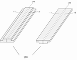
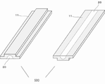
図1に磁性楔100の斜視図を示す。また、磁性楔100を裏返しにしたときの斜視図を同図中右側に示す。磁性楔100は、異なる透磁率を有する複数の部分からなり、本実施形態では、全体として断面が凸形状となっている。そして、磁性楔100の幅方向の一端から逆側の一端に向かって、第一の高透磁率部分11、低透磁率部分20、第二の高透磁率部分12の順で形成されている。つまり、高透磁率部分11と12は磁性楔100の軸方向両端側に位置し、低透磁率部分20は、磁性楔100の軸方向中央側で、凸形状の突出部分の範囲内に位置しており、磁性楔100の長手方向に沿って細長く形成されている。また、低透磁率部分20は、磁性楔100を厚さ方向に貫通するように配置されている。なお、磁性楔100の概略寸法は、例えば、長手方向が20mmから300mm、幅方向が2mm〜20mm、厚みが1〜5mm程度である。
(First Embodiment)
FIG. 1 shows a perspective view of the
図2は、高透磁率部分11または12と、低透磁率部分20の境界を拡大して示した模式図である。高透磁率部分11及び12は、複数のFe基軟磁性合金粒子で構成され、より具体的には、Feよりも酸化しやすい元素Mを含有する複数のFe基軟磁性合金粒子1の圧密体である。そして、圧密体の粒子間に、空隙2と、Fe基軟磁性合金粒子1同士を結着するFe基軟磁性合金粒子の表面酸化物相3とを有している。かかる表面酸化物相は元素Mを含む酸化物相である。
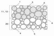
FIG. 2 is a schematic view showing an enlarged boundary between the high
また、低透磁率部分20は、Fe基軟磁性合金粒子1より透磁率が低い複数の低透磁率金属粒子4で構成される。ここで低透磁率金属粒子4は、Feよりも酸化しやすい元素Mを含有することを特徴とする。そして、低透磁率金属粒子4の粒子間に空隙2と、低透磁率金属粒子4同士を結着する表面酸化物相5とを有している。かかる表面酸化物相は元素Mを含む酸化物相である。
Further, the low
さらに、Fe基軟磁性合金粒子1と低透磁率金属粒子4とが隣接する場所においては、表面酸化物相6が形成されている。表面酸化物相6は、Fe基軟磁性合金粒子1の表面酸化物相3と低透磁率金属粒子4の表面酸化物相5が接合して一体化したものであって、隣接する粒子により成分が異なる相となる。ただし、Fe基軟磁性合金粒子1と低透磁率金属粒子4に、同じ元素Mを含有することで、表面酸化物相6を、元素Mを主体とする、より均質な表面酸化物相6にすることができる。これにより、Fe基軟磁性合金粒子1および低透磁率金属粒子4の粒子間を強固に結着することができる。
Further, a
磁性楔100を構成する各合金粒子を上述のように表面酸化物相で強固に結着することにより、磁性楔100の曲げ強度を高くすることができる。また、表面酸化物相は絶縁体であるため、磁性楔100を構成する各合金粒子間を電気的に隔絶し、磁性楔100を全体として高電気抵抗とすることができる。これにより、磁性楔100に生じる渦電流損失を効果的に抑制することができる。
The bending strength of the
ここで、Fe基軟磁性合金粒子1は、他の元素よりFeの含有量が質量比で最も多い軟磁性合金粒子であり、CoやNiを含有する軟磁性合金粒子にしてもよい。ただし、CoやNiの含有量はFeの含有量を超えてはならない。 Here, the Fe-based soft magnetic alloy particles 1 are soft magnetic alloy particles having the highest Fe content in terms of mass ratio compared to other elements, and may be soft magnetic alloy particles containing Co or Ni. However, the content of Co and Ni must not exceed the content of Fe.
Fe基軟磁性合金粒子1の粒径を小さくすることで、磁性楔100自身に発生する渦電流損失低減に有利である一方、粒径が小さいと、粒子の製造自体が困難になる可能性がある。そこで、磁性楔100の断面観察像において、Fe基軟磁性合金粒子1の各粒子の最大径の平均は、0.5μm以上、15μm以下であるのが好ましく、0.5μm以上、8μm以下であるのがより好ましい。また、最大径が40μmを超える粒子個数比率は、1.0%未満であるのが好ましい。
Reducing the particle size of the Fe-based soft magnetic alloy particles 1 is advantageous for reducing the eddy current loss generated in the
なお、ここで言うFe基軟磁性合金粒子1の各粒子の最大径の平均とは、磁性楔100の断面を研磨して顕微鏡観察を行い、一定の面積の視野内に存在する30個以上の粒子の最大径を読み取ったそれらの平均値のことである。
The average of the maximum diameters of each of the Fe-based soft magnetic alloy particles 1 referred to here is 30 or more particles existing in a field of view of a certain area after polishing the cross section of the
また、Fe基軟磁性合金粒子1は、Feよりも酸化しやすい元素Mを含有する粒子である。ここで、「Feよりも酸化しやすい元素M」とは、酸化物の標準生成ギブズエネルギーが、Fe2O3よりも低い元素を意味している。この条件を満たす元素は、元素Mとして選択できるが、過激な反応性や毒性が少なく、磁気楔100を製造しやすいので、Al、Si、Cr、Zr、Hfから選択するのが好ましい。
Further, the Fe-based soft magnetic alloy particle 1 is a particle containing an element M that is more easily oxidized than Fe. Here, "element M that is more easily oxidized than Fe" means an element having a standard Gibbs energy of oxide lower than Fe 2 O 3. An element satisfying this condition can be selected as the element M, but it is preferably selected from Al, Si, Cr, Zr, and Hf because it has little radical reactivity and toxicity and it is easy to manufacture the
このような元素Mを含有することで、Fe基軟磁性合金粒子1同士を強固に結着する良好な表面酸化物相3を容易に形成することができる。具体的には、複数のFe基軟磁性合金粒子1を、成形後に酸化することで、元素Mの含有量がFe基軟磁性合金粒子1の内部よりも高い表面酸化物相3を、容易に形成することができる。特に、元素MにAlを選択した場合、とりわけ化学的に安定で電気抵抗の高い良好な表面酸化物相3が得られるので好ましい。
By containing such an element M, a good
また、Fe基軟磁性合金粒子1に含有される元素Mの量は、少な過ぎると、Fe基軟磁性合金粒子1を酸化しても、元素Mの含有量がFe基軟磁性合金粒子1の内部よりも高い、良好な表面酸化物相3を形成しにくくなり、多過ぎると、Fe濃度が薄まるのでFe基軟磁性合金粒子1の飽和磁束密度とキュリー温度が低下してしまう可能性がある。
Further, if the amount of the element M contained in the Fe-based soft magnetic alloy particles 1 is too small, the content of the element M is the Fe-based soft magnetic alloy particles 1 even if the Fe-based soft magnetic alloy particles 1 are oxidized. It becomes difficult to form a good
そこで、Fe基軟磁性合金粒子1に含有される元素Mの量は、1.0質量%以上20質量%以下にするのが好ましい。このようにすることで、良好な表面酸化物相3を容易に形成でき、Fe基軟磁性合金粒子1の飽和磁束密度とキュリー温度を高く維持することができる。
Therefore, the amount of the element M contained in the Fe-based soft magnetic alloy particles 1 is preferably 1.0% by mass or more and 20% by mass or less. By doing so, a good
また、元素Mは、一種だけでなく二種以上選択してもよい。例えば、AlとCrの二種を選択して、Fe基軟磁性合金粒子1を、Fe−Al−Cr系合金粒子にしてもよい。このようにすることで、比較的少ないAl量でも、元素Mの含有量の合計がFe基軟磁性合金粒子1の内部よりも高い、良好な表面酸化物相3を形成することができる。すなわち、曲げ強度と電気抵抗が高い磁性楔100にすることができる。なお、Fe−Al−Cr系合金とは、Feの次に含有量が多い元素が、CrおよびAl(順不同)である合金のことであり、その他の元素がFe、Cr、Alより少量含まれていても良い。Fe−Al−Cr系合金の組成はこれを特に限定するものではないが、例えばAlの含有量としては、好ましくは2.0質量%以上、より好ましくは5.0質量%以上である。高飽和磁束密度を得る観点からは、Alの含有量は、好ましくは10.0質量%以下、より好ましくは6.0質量%以下である。また、Crの含有量は、好ましくは1.0質量%以上、より好ましくは2.5質量%以上である。高飽和磁束密度を得る観点からは、Crの含有量は、好ましくは9.0質量%以下、より好ましくは4.5質量%以下である。
Further, the element M may be selected not only by one type but also by two or more types. For example, two types of Al and Cr may be selected to make the Fe-based soft magnetic alloy particles 1 into Fe—Al—Cr based alloy particles. By doing so, it is possible to form a good
なお、上記元素Mに二種以上の元素を選択した場合、それら含有量の合計は、一種を選択した場合と同様に、1.0質量%以上20質量%以下にするのが好ましい。 When two or more kinds of elements are selected for the element M, the total content thereof is preferably 1.0% by mass or more and 20% by mass or less, as in the case of selecting one kind.
また、Fe基軟磁性合金粒子1は、上記元素M以外の元素が添加された粒子にしてもよい。ただし、これら添加元素は、元素Mより少量添加するのが好ましい。さらに、化学的手法や熱処理などで表面処理された粒子にしてもよい。また、Fe基軟磁性合金粒子1は、組成が異なる複数種のFe基軟磁性合金粒子で構成することもできる。 Further, the Fe-based soft magnetic alloy particles 1 may be particles to which an element other than the element M is added. However, it is preferable to add these additive elements in a smaller amount than the element M. Further, the particles may be surface-treated by a chemical method or heat treatment. Further, the Fe-based soft magnetic alloy particles 1 can also be composed of a plurality of types of Fe-based soft magnetic alloy particles having different compositions.
また、表面酸化物相3は、元素M以外にFeやその他の元素を含有する表面酸化物相3にしてもよく、元素MやFeなどの元素濃度は、表面酸化物相3の内部において必ずしも均一である必要はない。すなわち、粒界ごとに元素濃度が異なっていてもよい。
Further, the
表面酸化物相3の厚さは、薄いと、粒子同士の電気的な隔絶が小さくなって、磁性楔100の電気抵抗が低下する可能性がある。一方、厚いと透磁率が低くなり過ぎて、磁性楔としての効果が弱くなる可能性がある。そこで、表面酸化物相3の厚さは、例えば0.01〜1.0μmにするのが好ましい。
If the thickness of the
低透磁率金属粒子4は、Fe基軟磁性合金粒子1よりも透磁率の低い粒子であり、強磁性体でも非磁性体でも良い。ここで言う「非磁性」とは室温にて強磁性でないことを意味する。具体的には、室温にて常磁性、反磁性、反強磁性のいずれかの磁性を示す粒子を意味している。
The low magnetic
また、低透磁率金属粒子4は、Fe基軟磁性合金粒子1に含まれる元素M、すなわち、Feよりも酸化しやすい元素Mを含む粒子であることが好ましい。例えば、Al、Si、Cr、Zr、Hfから選択される元素Mを含むことができる。このような元素Mを含むことで、低透磁率金属粒子4の表面に、Fe基軟磁性合金粒子1の表面に類する、良好な表面酸化物相5を形成することができ、低透磁率金属粒子4同士の粒子間を強固に結着することができる。
Further, the low magnetic
また、表面酸化物相6は、Fe基軟磁性合金粒子1の表面酸化物相3と低透磁率金属粒子4の表面酸化物相が接合して一体化したものであって、隣接する粒子により成分が異なる相となる。ただし、Fe基軟磁性合金粒子1と低透磁率金属粒子4に、同じ元素Mを含有することで、表面酸化物相6を、元素Mを主体とする、より均質な表面酸化物相6にすることができる。これにより、Fe基軟磁性合金粒子1と低透磁率金属粒子4の粒子間を強固に結着して、曲げ強度の高い磁性楔100にすることができる。
Further, the
また、低透磁率金属粒子4は、元素M単体の粒子にしてもよいし、元素Mを含有する合金粒子にしてもよい。合金粒子にする場合には、Fe基の合金粒子にし、Fe基軟磁性合金粒子よりも元素Mの濃度を高めて(即ちFeの含有量を少なくして)透磁率を下げるか、あるいはさらに元素Mの濃度を高めて粒子のキュリー温度を室温以下にしても良い。この場合、キュリー温度は−20℃以下が好ましく、−100℃以下にするのがさらに好ましい。
低透磁率金属粒子4をFe基の合金粒子とする場合、例えば、AlまたはCrの少なくとも一方を含む金属粒子であることが好ましく、AlとCrの二種の元素Mを選択し、Fe−Al−Cr系合金粒子にすることがより好ましい。このようにすることで、良好な表面酸化物相5および6を形成することができ、曲げ強度の高い磁性楔100にすることができる。
Further, the low magnetic
When the low magnetic
なお、低透磁率金属粒子4は、粒径が大きいと、Fe基軟磁性合金粒子1との結着を阻害する可能性や、電気抵抗が低くなって低透磁率部分20に生じる渦電流損失が増大する可能性がある。一方、粒径が小さいと、粒子の製造自体が困難になる可能性がある。そこで、磁性楔200の断面観察像において、非磁性粒子4の各粒子の最大径の平均は、0.5μm以上、15μm以下であるのが好ましく、0.5μm以上、8μm以下であるのがより好ましい。また、最大径が40μmを超える粒子個数比率は、1.0%未満であるのが好ましい。
If the particle size of the low magnetic
ここで、磁性楔100の電気抵抗は、高いほど好ましく、体積抵抗率の値で10Ωm以上であるのが好ましく、100Ωm以上であるのがより好ましい。そして、1000Ωm以上であるのがさらに好ましい。
また、磁性楔100の曲げ強度も、高いほど好ましく、三点曲げ強度の値で150MPa以上であるのが好ましく、200MPa以上であるのがより好ましい。そして、250MPa以上であるのがさらに好ましい。
Here, the higher the electrical resistance of the
Further, the higher the bending strength of the
上述のように従来の磁性楔には樹脂が含まれているため、高温環境下では樹脂が軟化して強度が低下してしまう可能性がある。すなわち、回転電機のような高温下で使用すると、曲げ強度に課題を生じる可能性がある。これに対して、本実施形態の磁性楔100は、樹脂ではなく表面酸化物相で粒子同士を接合しているので、高温下で粒子同士の結着強度が低下することを抑制でき、高温下でも曲げ強度の高い磁性楔100が提供できる。例えば、室温(25℃)から150℃に昇温したときの三点曲げ強度の低下率を5%未満、より好ましくは3%未満にすることができる。さらには、室温(25℃)から200℃に昇温したときの三点曲げ強度の低下率も10%未満、より好ましくは5%未満にすることができる。
As described above, since the conventional magnetic wedge contains a resin, the resin may soften and its strength may decrease in a high temperature environment. That is, when used at a high temperature such as a rotary electric machine, there is a possibility that a problem arises in bending strength. On the other hand, in the
さらに、樹脂を含む従来の磁性楔には、高温環境下に長時間さらされると樹脂が分解劣化して不可逆的な強度低下と寸法減少を引き起こすという課題があった。これに対し、本実施形態の磁性楔100では、基体に樹脂を含まないため、そのような問題は発生しない。この点においても、耐熱性と長期信頼性に優れた磁性楔100が提供できる。例えば、180℃で1000時間経過後の質量の減量率を0.05%未満、より好ましくは0.03%未満にすることができる。さらには、220℃で450時間経過後の質量の減量率も0.1%未満、より好ましくは0.05%未満にすることができる。
Further, the conventional magnetic wedge containing a resin has a problem that the resin is decomposed and deteriorated when exposed to a high temperature environment for a long time, causing an irreversible decrease in strength and size. On the other hand, in the
また、回転電機の耐熱温度は、用途や仕様により異なるものの、規格上155℃や180℃と設定されるものがある。加えて、一部の回転電機では、200℃程度にまで上昇するものもある。本実施形態の磁性楔100は、高温下でも優れた曲げ強度を維持できるので、これまで磁性楔が設置できなかった、最高温度が180℃を超える回転電機、さらには200℃を超えるような回転電機にも好適に用いることができる。
Further, although the heat resistant temperature of the rotary electric machine varies depending on the application and specifications, there are some that are set to 155 ° C. or 180 ° C. according to the standard. In addition, in some rotary electric machines, the temperature rises to about 200 ° C. Since the
また、本実施形態の磁性楔100は、表面に電気絶縁性被覆が形成されていることが好ましい。このようにすることで、磁性楔100の電気抵抗をさらに高くするとともに、圧密体表面からの粒子の脱落を抑制して、信頼性の高い磁性楔100にすることができる。被覆には、渦電流損失を抑制するために、樹脂や酸化物による電気絶縁性被覆が好ましく、例えばエポキシ樹脂による粉体塗装や、ゾルーゲル法による無機物の被覆、あるいはワニスやシリコン樹脂の含浸による封孔処理被覆を採用することができる。これらのうち、樹脂の高温劣化を回避する観点から、ゾルーゲル法による無機物の被覆が特に好ましい。
Further, it is preferable that the
(第2実施形態)
次に、本発明の第2実施形態の磁性楔200について説明する。本実施形態の磁性楔200と第1実施形態の磁性楔100とは、高透磁率部分と低透磁率部分の形状だけが異なるので、斜視図を用いてのみ説明する。また、第1実施形態と同じ構成は、作用効果が同じなので、同じ記号を付して説明を省略する。
(Second Embodiment)
Next, the
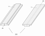
図3に磁性楔200の斜視図を示す。また、磁性楔200を裏返しにしたときの斜視図を同図中右側に示す。図のように、低透磁率部分20は磁性楔200の厚み方向に貫通しておらず、磁性楔200の表側(凸面側)の面は高透磁率部分11で覆われている。この面をロータ側に向けて回転電機内に磁性楔200を設置することによって、ロータとステータのギャップ内磁束密度分布をよりなだらかにできるとともに、磁性楔200を介してティース間に短絡する磁束を効果的に抑制できる。これにより、回転電機の高効率化と高トルク特性の両立を実現することができる。
FIG. 3 shows a perspective view of the
(第3実施形態)
次に、本発明の第3実施形態の磁性楔300について説明する。本実施形態の磁性楔300と第1実施形態の磁性楔100とは、高透磁率部分と低透磁率部分の形状だけが異なるので、斜視図を用いてのみ説明する。また、第1実施形態と同じ構成は、作用効果が同じなので、同じ記号を付して説明を省略する。
(Third Embodiment)
Next, the
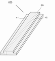
図4に磁性楔300の斜視図を示す。また、磁性楔300を裏返しにしたときの斜視図を同図中右側に示す。図のように、低透磁率部分20の断面形状が略台形形状をしている。さらに、低透磁率部分20は磁性楔300を貫通し、台形の短辺が磁性楔300の表側、長辺が磁性楔300の裏側に位置するように形成されている。磁性楔300の表側(台形形状の短辺側)をロータ側に向けて回転電機内に磁性楔300を設置することによって、ロータとステータのギャップ内磁束密度分布をさらになだらかにできるとともに、磁性楔300を介してティース間に短絡する磁束を効果的に抑制できる。これにより、回転電機の高効率化と高トルク特性の両立を実現することができる。
FIG. 4 shows a perspective view of the
(第4実施形態)
次に、本発明の第4実施形態の磁性楔400について説明する。本実施形態の磁性楔400と第1実施形態の磁性楔100とは、高透磁率部分と低透磁率部分の形状だけが異なるので、斜視図を用いてのみ説明する。また、第1実施形態と同じ構成は、作用効果が同じなので、同じ記号を付して説明を省略する。
(Fourth Embodiment)
Next, the
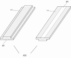
図5に磁性楔400の斜視図を示す。また、磁性楔400を裏返しにしたときの斜視図を同図中右側に示す。図のように、低透磁率部分20の断面が略三角形状をしており、三角形の底辺が磁性楔400の裏側(凸面の反対側)に位置するように形成されている。さらに、低透磁率部分20は磁性楔200の厚み方向に貫通しておらず、磁性楔400の表側の面は高透磁率部分11で覆われている。この面をロータ側に向けて回転電機内に磁性楔400を設置することによって、ロータとステータのギャップ内磁束密度分布をよりなだらかにできるとともに、磁性楔400を介してティース間に短絡する磁束を効果的に抑制できる。これにより、回転電機の高効率化と高トルク特性の両立を実現することができる。
FIG. 5 shows a perspective view of the
(第5実施形態)
次に、本発明の第5実施形態の磁性楔500について説明する。本実施形態の磁性楔500と第1実施形態の磁性楔100とは、高透磁率部分と低透磁率部分の形状だけが異なるので、斜視図を用いてのみ説明する。また、第1実施形態と同じ構成は、作用効果が同じなので、同じ記号を付して説明を省略する。
(Fifth Embodiment)
Next, the
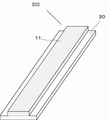
図6に磁性楔500の斜視図を示す。また、磁性楔500を裏返しにしたときの斜視図を同図中右側に示す。図のように、低透磁率部分20の断面が略半円形状をしており、半円の弦が磁性楔500の裏側に位置するように形成されている。さらに、低透磁率部分20は磁性楔500の厚み方向に貫通しておらず、磁性楔500の表側の面は高透磁率部分11で覆われている。この面をロータ側に向けて回転電機内に磁性楔500を設置することによって、ロータとステータのギャップ内磁束密度分布をよりなだらかにできるとともに、磁性楔500を介してティース間に短絡する磁束を効果的に抑制できる。これにより、回転電機の高効率化と高トルク特性の両立を実現することができる。
FIG. 6 shows a perspective view of the
(第6実施形態)
次に、本発明の第6実施形態の磁性楔600について説明する。本実施形態の磁性楔600と第1実施形態の磁性楔100とは、高透磁率部分と低透磁率部分の形状だけが異なるので、斜視図を用いてのみ説明する。また、第1実施形態と同じ構成は、作用効果が同じなので、同じ記号を付して説明を省略する。
(Sixth Embodiment)
Next, the
図7に磁性楔600の斜視図を示す。図のように、低透磁率部分20は磁性楔600の厚さ方向に貫通するとともに、磁性楔600の長手方向に斜めに形成されている。これにより、ロータとステータのギャップ内磁束密度分布をよりなだらかにできるとともに、磁性楔600を介してティース間に短絡する磁束を効果的に抑制でき、回転電機の高効率化と高トルク特性の両立を実現することができる。
FIG. 7 shows a perspective view of the
(第7実施形態)
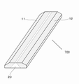
磁性楔は後述のようにステータのティースに形成された突起や溝に嵌合されて取り付けられる。したがって、この嵌合形態によって、磁性楔の断面は種々の形状をとることができる。上述の実施形態では磁性楔の両端に段差を設けた形状で説明したが、例えば図8に示したように、磁性楔700の両端がテーパー状になっていてもよい。また、図8に示した磁性楔700では低透磁率部分20の断面が台形となっているが、これに限らず、低透磁率部分の形状についても上述のような種々の形状を適用することができる。
(7th Embodiment)
The magnetic wedge is fitted and attached to a protrusion or groove formed on the tooth of the stator as described later. Therefore, depending on this fitting form, the cross section of the magnetic wedge can take various shapes. In the above-described embodiment, the shape is described in which steps are provided at both ends of the magnetic wedge, but as shown in FIG. 8, for example, both ends of the
(第8実施形態)
次に、本発明の第8実施形態の磁性楔800について説明する。図9に磁性楔800の斜視図を示す。磁性楔800では、凸面側の凸部分全体が低透磁率部分20で構成されており、厚さ方向に、高透磁率部分11と低透磁率部分20の二層構造となっている。そして、高透磁率部分11側の面をロータ側に向けて磁性楔800を回転電機内に設置することにより、このような構成でも、回転電機の高効率化とトルク低下抑制に有効である。
(8th Embodiment)
Next, the
(第9実施形態)
次に、本発明の第9実施形態である、回転電機30について説明する。
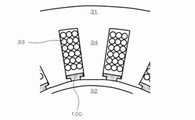
図10は、回転電機30の模式図であり、回転電機30の回転軸に垂直な断面構造を示している。回転電機30は、ラジアルギャップ型回転電機であり、ステータ31とロータ32を同軸にして配している。そして、ステータ31には、コイル33を巻き回した複数のティース34を、周方向に等間隔に配している。
(9th Embodiment)
Next, the rotary electric machine 30 which is the ninth embodiment of the present invention will be described.
FIG. 10 is a schematic view of the rotary electric machine 30 and shows a cross-sectional structure perpendicular to the rotation axis of the rotary electric machine 30. The rotary electric machine 30 is a radial gap type rotary electric machine, and the
本実施形態の回転電機30では、ティース34のロータ32側先端に、隣り合うティース34の先端を接続するよう、上述の磁気楔を配している。また、磁性楔の断面形状は凸形をしており、この凸部がロータ側に位置するように配置されている。磁性楔にはコイル33によってロータ側に押し出される方向に力が加わるが、磁性楔の鍔部がティース先端の突起部に押し付けられて磁性楔が固定される。
In the rotary electric machine 30 of the present embodiment, the above-mentioned magnetic wedge is arranged so as to connect the tips of
ここで、ティース34の比透磁率と飽和磁束密度は、通常、磁性楔のそれらよりも高く設計される。これにより、磁性楔に達したロータ32からの磁束は、磁性楔を経由してティース34に流入し、コイルに達する磁束が抑制されて、コイルに生じる渦電流損失を低減することができる。また、回転電機の駆動時において、コイル電流により生じたティース34内の磁束は、大部分がギャップを隔ててロータ32に流入するものの、一部は磁性楔に誘引されて周方向に広がるようになる。これにより、ステータ31とロータ32との間のギャップ内磁束分布がなだらかになり、例えばロータ32に永久磁石を配置した回転電機では、コギングを抑制することができ、さらにロータ32に発生する渦電流損失を低減することができる。また、例えばロータ32にかご形導体を配置した誘導型回転電機では、二次銅損を低減することができる。以上のように本発明による磁性楔を回転電機に配することで、損失を低減し、高効率・高性能の回転電機30にすることができる。
Here, the relative permeability and saturation magnetic flux density of the
磁性楔100または200の厚み(回転電機の径方向の寸法)は、薄すぎると強度が低下するほか、磁性楔としての効果も弱まるので、厚みは1mm以上であるのが好ましい。一方、厚すぎるとコイル33のスペースを圧迫して銅損増大の一因になるほか、磁性楔100または200の体積が増大するので磁性楔自体に生じる損失(ヒステリシス損失)も増大する。従って、厚みは5mm以下が好ましく、3mm以下がより好ましく、2mm以下がさらに好ましい。
磁性楔100または200の幅(回転電機の周方向の寸法)は、隣接するティース34の間隔に合わせて適宜設定されるが、2mmから20mmの範囲にあることが好ましい。
磁性楔100または200の長さ(回転電機の軸方向の寸法)も、基本的にはステータ31の厚み(軸方向長さ)に合わせて適宜設定されるが、長すぎると作製自体が困難になるほか、回転電機への取り付け時に折れやすくなって作業性が悪くなる。従って長さは、300mm以下が好ましく、200mm以下がより好ましく、100mm以下がさらに好ましい。一方、短すぎると、回転電機への取り付け時に作業が煩雑となって好ましくない。かかる観点から、長さは25mm以上が好ましく、50mm以上がより好ましい。
If the thickness of the
The width of the
The length of the
(第10実施形態)
次に、磁性楔の製造方法について説明する。以下の説明は、上述の実施形態である磁性楔100〜800のいずれにも適用できるものである。
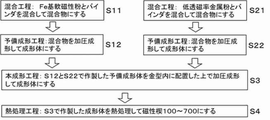
図11は、本発明の磁性楔100〜800を製造する工程フローである。本製造方法は、Fe基軟磁性粉末とバインダとを混合して混合物にする工程S11と、混合物を加圧成形して第一の成形体にする工程S12と、低透磁率金属粉末をバインダと混合して混合物にする工程S21と、混合物を加圧成形して第2の成形体にする工程S22と、第1の成形体と第2の成形体を金型内の所定位置にセットした上で、加圧成形して、第1の成形体と第2の成形体と一体化した成形体にする工程S3と、一体化された成形体を熱処理して磁性楔100〜800となる圧密体にする工程S4とを有している。
(10th Embodiment)
Next, a method for manufacturing the magnetic wedge will be described. The following description is applicable to any of the
FIG. 11 is a process flow for manufacturing the
まず、工程S11では、Fe基軟磁性粉末とバインダとを混合して混合物にする。工程S11に用いるFe基軟磁性粉末は、磁性楔100〜800でFe基軟磁性合金粒子1となる粉末である。Feを主体とした軟磁性合金粉末であり、CoやNiを含有する軟磁性粉末を用いてもよい。なお、以降の説明では、Fe基軟磁性粉末の粒子をFe基軟磁性合金粒子1と称する場合がある。
First, in step S11, the Fe-based soft magnetic powder and the binder are mixed to form a mixture. The Fe-based soft magnetic powder used in step S11 is a powder that becomes Fe-based soft magnetic alloy particles 1 with
Fe基軟磁性粉末には、平均粒径(累積粒度分布におけるメジアン径d50)が、1μm以上100μm以下の粉末を用いるのが好ましく、5μm以上30μm以下の粉末を用いるのがより好ましい。このようなFe基軟磁性粉末を用いることで、好ましい平均粒径のFe基軟磁性合金粒子1を有する磁性楔100〜800を製造することができる。
As the Fe-based soft magnetic powder, it is preferable to use a powder having an average particle size (median diameter d50 in the cumulative particle size distribution) of 1 μm or more and 100 μm or less, and more preferably 5 μm or more and 30 μm or less. By using such Fe-based soft magnetic powder,
また、Fe基軟磁性粉末には、Feよりも酸化しやすい元素Mを含有する粉末を用い、元素Mは、例えば、Al、Si、Cr、Zr、Hfから選択するのが好ましい。このようにすることで、工程S4において、Fe基軟磁性合金粒子1に良好な表面酸化物相3を容易に形成することができる。具体的には、Fe基軟磁性粉末の成形体を酸化することで、元素Mの含有量がFe基軟磁性合金粒子1の内部よりも高い表面酸化物相3を、容易に形成することができる。
Further, as the Fe-based soft magnetic powder, a powder containing an element M that is more easily oxidized than Fe is used, and the element M is preferably selected from, for example, Al, Si, Cr, Zr, and Hf. By doing so, in step S4, a good
なお、Fe基軟磁性粉末に含有される元素Mの量は、1.0質量%以上20質量%以下にするのが好ましい。このようにすることで、電気抵抗と曲げ強度が高く、磁気シールド性の高い磁性楔100〜800を、容易に製造することができる。
The amount of the element M contained in the Fe-based soft magnetic powder is preferably 1.0% by mass or more and 20% by mass or less. By doing so,
また、元素Mは、一種だけでなく二種以上選択してもよい。例えば、AlとCrの二種を選択して、Fe基軟磁性粉末を、Fe−Al−Cr系合金粉末にしてもよい。このようにすることで、曲げ強度が高く、比透磁率が調整された磁性楔100〜800を、容易に製造することができる。なお、Fe−Al−Cr系合金とは、Feの次に含有量が多い元素が、CrおよびAl(順不同)である合金のことであり、その他の元素がFe、Cr、Alより少量で含まれていても良い。
Further, the element M may be selected not only by one type but also by two or more types. For example, two types of Al and Cr may be selected, and the Fe-based soft magnetic powder may be an Fe—Al—Cr-based alloy powder. By doing so, it is possible to easily manufacture
なお、上記元素Mとして、二種以上の元素を選択した場合、それら含有量の合計は、一種を選択した場合と同様に、1.0質量%以上20質量%以下にするのが好ましい。 When two or more kinds of elements are selected as the element M, the total content thereof is preferably 1.0% by mass or more and 20% by mass or less, as in the case of selecting one kind.
また、Fe基軟磁性粉末には、上記元素M以外の元素を添加した粉末を用いてもよい。ただし、これら添加元素は、元素Mより少量添加するのが好ましい。さらに、化学的手法や熱処理などで表面処理した粒子を含む粉末を用いてもよい。 Further, as the Fe-based soft magnetic powder, a powder to which an element other than the above element M is added may be used. However, it is preferable to add these additive elements in a smaller amount than the element M. Further, a powder containing particles surface-treated by a chemical method or heat treatment may be used.
また、Fe基軟磁性粉末には、成形性の良い粒状粉として、ガスアトマイズ法や水アトマイズ法により作製した粉末を用いることができる。また、形状異方性の活用を目的とした偏平粉として、粉砕法により作製した粉末を用いることができる。 Further, as the Fe-based soft magnetic powder, a powder prepared by a gas atomizing method or a water atomizing method can be used as a granular powder having good moldability. Further, as a flat powder for the purpose of utilizing shape anisotropy, a powder produced by a pulverization method can be used.
また、バインダは工程S12において粒子同士を仮接着して、成形体にある程度の強度を付与するために用いられる。また、バインダには粒子間に適切な間隔を付与する役割もある。バインダとしては、例えばポリビニルアルコールやアクリルなどの有機バインダを用いることができる。また、バインダは、混合物全体に十分に行きわたり、十分な成形体強度を確保しつつ、工程S4において、十分熱分解される量だけ添加するのが好ましい。例えば、Fe基軟磁性粉末100重量部に対して0.5〜3.0重量部だけ添加するのが好ましい。 Further, the binder is used in step S12 to temporarily bond the particles to each other to impart a certain degree of strength to the molded product. The binder also has the role of providing an appropriate spacing between the particles. As the binder, for example, an organic binder such as polyvinyl alcohol or acrylic can be used. Further, it is preferable to add the binder in an amount that is sufficiently thermally decomposed in the step S4 while sufficiently spreading the binder throughout the mixture and ensuring sufficient strength of the molded product. For example, it is preferable to add only 0.5 to 3.0 parts by weight with respect to 100 parts by weight of the Fe-based soft magnetic powder.
また、工程S11における混合方法は、公知の混合方法、混合機を用いることができる。Fe基軟磁性粉末とバインダとを混合した混合物は、バインダの接着作用により、広い粒度分布をもった凝集粉になることがある。その場合、混合粉を、例えば振動篩等を用いて篩に通し、所望の二次粒子径の造粒粉にしてから、工程S12に用いてもよい。球状、かつ粒径の揃った造粒粉を得るためには、噴霧乾燥を適用することが好ましい。また、混合物には、工程S12における粉末と金型との摩擦を低減するために、ステアリン酸、ステアリン酸塩等の潤滑剤を添加してもよい。その場合、添加量は、混合粉100重量部に対して0.1〜2.0重量部にすることが好ましい。なお、潤滑剤は、工程S11で混合物に添加せず、S12工程で金型に塗布してもよい。 Further, as the mixing method in step S11, a known mixing method and mixer can be used. A mixture of Fe-based soft magnetic powder and a binder may become agglomerated powder having a wide particle size distribution due to the adhesive action of the binder. In that case, the mixed powder may be passed through a sieve using, for example, a vibrating sieve to obtain granulated powder having a desired secondary particle size, and then used in step S12. In order to obtain granulated powder having a spherical shape and a uniform particle size, it is preferable to apply spray drying. Further, a lubricant such as stearic acid or stearate may be added to the mixture in order to reduce the friction between the powder and the mold in step S12. In that case, the addition amount is preferably 0.1 to 2.0 parts by weight with respect to 100 parts by weight of the mixed powder. The lubricant may not be added to the mixture in step S11, but may be applied to the mold in step S12.
次に、工程S12では、工程S11で得られた混合物を加圧成形する。加圧成形には、例えば、プレス機と成形金型を用いることができる。高透磁率部分11および12のような段付き形状を成形するためには多軸プレス機を用いることが好ましい。加圧成形は、室温成形にしてもよいし、バインダが消失しない程度加熱した、温間成形にしてもよい。
成形圧力は、後の本成形工程で粒子の移動および塑性変形ができる余地を残しておく観点から、高すぎないことが好ましい。例えば、成形圧力は、0.9GPa以下が好ましく、0.7GPa以下がより好ましく、0.5GPa以下がさらに好ましい。一方、低すぎると成形体の形成が困難になるので、0.1GPa以上が好ましく、0.3GPa以上がより好ましい。
Next, in step S12, the mixture obtained in step S11 is pressure-molded. For pressure molding, for example, a press machine and a molding die can be used. It is preferable to use a multi-axis press to form stepped shapes such as the high
The molding pressure is preferably not too high from the viewpoint of leaving room for particle movement and plastic deformation in the subsequent main molding step. For example, the molding pressure is preferably 0.9 GPa or less, more preferably 0.7 GPa or less, and even more preferably 0.5 GPa or less. On the other hand, if it is too low, it becomes difficult to form a molded product, so 0.1 GPa or more is preferable, and 0.3 GPa or more is more preferable.
次に、工程S21では、低透磁率金属粉末とバインダとを混合して混合物にする。工程S21に供される低透磁率金属粉末は、磁性楔100〜800において低透磁率金属粒子4となる粉末である。なお、以降の説明では、低透磁率金属粉末の粒子を低透磁率金属粒子4、と称する場合がある。
Next, in step S21, the low magnetic permeability metal powder and the binder are mixed to form a mixture. The low magnetic permeability metal powder used in step S21 is a powder that becomes low magnetic
低透磁率金属粉末には、平均粒径(累積粒度分布におけるメジアン径d50)が、1μm以上80μm以下の粉末を用いるのが好ましく、3μm以上20μm以下の粉末を用いるのがより好ましい。このような低透磁率金属粉末を用いることで、好ましい平均粒径の低透磁率金属粒子4を有する磁性楔100〜800を製造することができる。
As the low magnetic permeability metal powder, it is preferable to use a powder having an average particle size (median diameter d50 in the cumulative particle size distribution) of 1 μm or more and 80 μm or less, and more preferably 3 μm or more and 20 μm or less. By using such a low magnetic permeability metal powder, it is possible to manufacture
また、低透磁率金属粉末には、Fe基軟磁性粉末に含まれる元素M、すなわち、Feよりも酸化しやすい元素Mを含む粉末を用い、元素Mは、例えば、Al、Si、Cr、Zr、Hfから選択するのが好ましい。このようにすることで、曲げ強度と電気抵抗の高い磁性楔100〜800を容易に製造することができる。
Further, as the low magnetic permeability metal powder, an element M contained in the Fe-based soft magnetic powder, that is, a powder containing an element M that is more easily oxidized than Fe is used, and the element M is, for example, Al, Si, Cr, Zr. , Hf is preferable. By doing so,
また、低透磁率金属粒子4は、元素M単体の粒子にしてもよいし、元素Mを含有する合金粒子にしてもよい。合金粒子にする場合には、Fe基の合金粒子にし、元素Mの濃度を高めて(即ちFeの含有量を少なくして)透磁率を下げるか、あるいはさらに元素Mの濃度を高めて粒子のキュリー温度を室温以下にしても良い。
低透磁率金属粒子4をFe基の合金粒子とする場合、例えば、AlまたはCrの少なくとも一方を含む金属粒子であることが好ましく、AlとCrの二種の元素Mを選択し、Fe−Al−Cr系合金粒子にすることがより好ましい。このようにすることで、良好な表面酸化物相5および6を形成することができ、曲げ強度と電気抵抗の高い磁性楔100〜800にすることができる。
Further, the low magnetic
When the low magnetic
工程S21に供されるバインダは、前述の工程11と同様のものが使用可能である。バインダの添加量についても同様である。また、工程S21における混合方法は、前述の工程S11と同じ混合方法を用いることができる。潤滑剤の添加量についても同様である。
As the binder provided in the step S21, the same binder as in the above-mentioned
次に、工程S22では、工程S21で得られた混合物を加圧成形する。加圧成形には、前述の工程S12と同じ加圧成形を用いることができる。成形圧力は、後の本成形工程で粒子の移動および塑性変形ができる余地を残しておく観点から、高すぎないことが好ましい。例えば、成形圧力は、0.9GPa以下が好ましく、0.7GPa以下がより好ましく、0.5GPa以下がさらに好ましい。一方、低すぎると成形体の形成が困難になるので、0.1GPa以上が好ましく、0.3GPa以上がより好ましい。 Next, in step S22, the mixture obtained in step S21 is pressure-molded. For the pressure molding, the same pressure molding as in the above-mentioned step S12 can be used. The molding pressure is preferably not too high from the viewpoint of leaving room for particle movement and plastic deformation in the subsequent main molding step. For example, the molding pressure is preferably 0.9 GPa or less, more preferably 0.7 GPa or less, and even more preferably 0.5 GPa or less. On the other hand, if it is too low, it becomes difficult to form a molded product, so 0.1 GPa or more is preferable, and 0.3 GPa or more is more preferable.
次に低透磁率金属粒子では、工程12および工程22で作製した成形体を、金型内の所定位置にセットした上で、改めて加圧成形を行い、これらの成形体を一体化させる。磁性楔100〜800を作製する場合には、高透磁率部分の成形体を両端に、低透磁率部分の成形体をそれらの間にセットした上で加圧成形を行う。加圧成形時の圧力によって、粒子の移動と塑性変形が生じ、全体の緻密化が進行するとともに、高透磁率部分の成形体と低透磁率部分の成形体が密着して一体化する。ただし、ここで言う密着とは、高透磁率部分と低透磁率部分の境界部において、Fe基軟磁性合金粒子1と低透磁率金属粒子4は、バインダを介して接着した状態となっていることを指す。
Next, for the low magnetic permeability metal particles, the molded bodies produced in
工程3の加圧成形には、例えば、プレス機と成形金型を用いることができる。加圧成形は、室温成形にしてもよいし、バインダが消失しない程度加熱した、温間成形にしてもよい。金型内壁に潤滑剤を塗布してもよい。成形圧力は、上述の一体化を促進するために、工程S12および工程S22での成形圧力よりも高くすることが好ましい。例えば、成形圧力は、0.7GPa以上が好ましく、0.9GPa以上がより好ましい。一方、高すぎると大型のプレス機が必要になり、金型の損耗が顕著になるため、2.5GPa以下が好ましく、2.0GPa以下がより好ましい。
For the pressure molding in
次に、工程S4では、工程S3で得られた成形体を熱処理して磁性楔100〜800となる圧密体にする。工程S4では、成形体を熱処理することで、成形体のFe軟磁性粒子1および低透磁率金属粒子4の粒子間に存在するバインダを熱分解して、粒子間に空隙を形成する。さらに熱処理を継続することで、上記の粒子間に、空隙2と、Fe基軟磁性合金粒子1同士を結着する表面酸化物相3と、低透磁率金属粒子4同士を結着する表面酸化物相5と、Fe基軟磁性合金粒子1と低透磁率金属粒子4を結着する表面酸化物相6とを形成する。
Next, in step S4, the molded body obtained in step S3 is heat-treated to be a compacted body having a magnetic wedge of 100 to 800. In step S4, the molded body is heat-treated to thermally decompose the binder existing between the Fe soft magnetic particles 1 and the low magnetic
なお、熱処理は、大気中、酸素と不活性ガスの混合気体中など、酸素が存在する雰囲気中で行うことができる。また、水蒸気と不活性ガスの混合気体中など、水蒸気が存在する雰囲気中で行うこともできる。 The heat treatment can be performed in an atmosphere in which oxygen is present, such as in the atmosphere or in a mixed gas of oxygen and an inert gas. It can also be performed in an atmosphere in which water vapor is present, such as in a mixed gas of water vapor and an inert gas.
また、熱処理は、Fe基軟磁性合金粒子1の粒子間に、Fe基軟磁性合金粒子1同士を結着する表面酸化物相3と、低透磁率金属粒子4同士を結着する表面酸化物相5と、Fe基軟磁性合金粒子1と低透磁率金属粒子4を結着する表面酸化物相6とを形成可能な温度に加熱して行う。ただし、熱処理温度が低いと、バインダの熱分解が完了せずに残存する可能性があるほか、成形時に成形体に加わった歪が緩和されずに残る可能性がある。一方、熱処理温度が高いと、Fe基軟磁性合金粒子1同士が焼結し、電気抵抗が下がって渦電流損失の大きい磁性楔100〜800になる可能性がある。そこで、熱処理温度は600℃〜900℃の範囲にするのが好ましく、700〜800℃の範囲にするのがより好ましい。
Further, in the heat treatment, the
なお、図11には記載していないが、工程S12、S22、S3の成形工程の後で、成形体に研削加工や切削加工(あるいはその両方)を施す加工工程を挿入してもよい。これにより、各成形体を所望の形状にすることができ、様々な実施形態の磁性楔100〜800が容易に得られるようになる。さらに、工程S4の熱処理工程後に加工工程を入れることも可能である。ただしこの場合、熱処理で形成された表面酸化相にダメージを与えて電気抵抗を下げるリスクがある。かかる観点から、成形体の段階で(熱処理前に)加工を行う製法がより好ましい。
Although not shown in FIG. 11, after the molding steps of steps S12, S22, and S3, a processing step of performing grinding and / or cutting on the molded body may be inserted. As a result, each molded product can be formed into a desired shape, and
上述のように本製造方法は、粉末原料のプレス成形を基本にしたものであり、所望の磁性楔形状を比較的容易に得ることができるため、量産性にも優れている。 As described above, this production method is based on press molding of a powder raw material, and a desired magnetic wedge shape can be obtained relatively easily, so that it is also excellent in mass productivity.
以上、本発明について、上記実施形態を用いて説明してきたが、本発明の技術範囲は、上記実施形態に限定されない。特許請求の範囲に記載されている技術範囲にて、内容を変更できるものである。 Although the present invention has been described above using the above-described embodiment, the technical scope of the present invention is not limited to the above-described embodiment. The contents can be changed within the technical scope described in the claims.
1:Fe基軟磁性合金粒子
2:空隙
3:表面酸化物相
4:低透磁率金属粒子
5:表面酸化物相
6:表面酸化物相
30:回転電機
31:ステータ
32:ロータ
33:コイル
34:ティース
100、200、300、400、500、600、700、800:磁性楔
1: Fe-based soft magnetic alloy particles 2: voids 3: surface oxide phase 4: low magnetic permeability metal particles 5: surface oxide phase 6: surface oxide phase 30: rotary electric machine 31: stator 32: rotor 33: coil 34 :
Claims (8)
異なる透磁率を有する複数の部分からなり、
前記複数の部分のうち、第1の部分は、Feより酸化しやすい元素Mを含有する複数のFe基軟磁性合金粒子が、
前記元素Mを含む酸化物相で結着されていること、
を特徴とする磁性楔。 A magnetic wedge for rotary electric machines
Consists of multiple parts with different magnetic permeability
Of the plurality of portions, the first portion contains a plurality of Fe-based soft magnetic alloy particles containing an element M that is more easily oxidized than Fe.
Being bound by an oxide phase containing the element M,
A magnetic wedge featuring.
Feよりも酸化しやすい元素Mを含有する複数の低透磁率金属粒子からなり、
前記低透磁率金属粒子が、前記元素Mを含む酸化物相で結着されていることを特徴とする請求項1に記載の磁性楔。 Of the plurality of portions, the second portion has a lower magnetic permeability than the Fe-based soft magnetic alloy particles.
It is composed of a plurality of low magnetic permeability metal particles containing an element M that is more easily oxidized than Fe.
The magnetic wedge according to claim 1, wherein the low magnetic permeability metal particles are bound by an oxide phase containing the element M.
を特徴とする請求項2または請求項3のいずれか一項に記載の磁性楔。 The boundary between the first portion and the second portion is bound by an oxide phase containing the element M.
The magnetic wedge according to any one of claims 2 and 3, wherein the magnetic wedge is characterized.
前記第1の部分が、磁性楔の幅方向両端側に位置し、
前記第2の部分が、磁性楔の幅方向中央側に位置すること
を特徴とする請求項2ないし請求項4のいずれか一項に記載の磁性楔。 Of the plurality of parts
The first portion is located on both ends in the width direction of the magnetic wedge.
The magnetic wedge according to any one of claims 2 to 4, wherein the second portion is located on the central side in the width direction of the magnetic wedge.
前記Fe基軟磁性合金粒子よりも低い透磁率を有し、前記元素Mを含有する複数の低透磁率金属粒子とバインダとを混合物にして、前記混合物を加圧成形して第2の成形体を作製する工程と、
前記第1の成形体と、前記第2の成形体とを金型内に組み合わせて配置して加圧成形を施し、前記第1の成形体と前記第2の成形体が一体化された成形体を作製する工程と、
前記成形体に熱処理を施し、前記Fe基軟磁性合金粒子の間、前記低透磁率金属粒子の間、および前記Fe基軟磁性合金粒子と前記低透磁率金属粒子の間に、
前記元素Mを含む酸化物相を生成させ、前記酸化物相で各粒子を結着させる工程と、
を有することを特徴とする磁性楔の製造方法。
A step of making a mixture of a plurality of Fe-based soft magnetic alloy particles containing an element M that is more easily oxidized than Fe and a binder, and pressure-molding the mixture to prepare a first molded body.
A second molded body is formed by mixing a plurality of low magnetic permeability metal particles having a magnetic permeability lower than that of the Fe-based soft magnetic alloy particles and containing the element M and a binder, and press-molding the mixture. And the process of making
The first molded body and the second molded body are combined and arranged in a mold to perform pressure molding, and the first molded body and the second molded body are integrated. The process of making a body and
The molded body is heat-treated, and between the Fe-based soft magnetic alloy particles, between the low magnetic permeability metal particles, and between the Fe-based soft magnetic alloy particles and the low magnetic permeability metal particles.
A step of generating an oxide phase containing the element M and binding each particle with the oxide phase.
A method for manufacturing a magnetic wedge, which comprises.
Priority Applications (1)
| Application Number | Priority Date | Filing Date | Title |
|---|---|---|---|
| JP2020033632A JP2021136838A (en) | 2020-02-28 | 2020-02-28 | How to make magnetic wedges, rotary electric machines, and magnetic wedges |
Applications Claiming Priority (1)
| Application Number | Priority Date | Filing Date | Title |
|---|---|---|---|
| JP2020033632A JP2021136838A (en) | 2020-02-28 | 2020-02-28 | How to make magnetic wedges, rotary electric machines, and magnetic wedges |
Publications (1)
| Publication Number | Publication Date |
|---|---|
| JP2021136838A true JP2021136838A (en) | 2021-09-13 |
Family
ID=77661874
Family Applications (1)
| Application Number | Title | Priority Date | Filing Date |
|---|---|---|---|
| JP2020033632A Pending JP2021136838A (en) | 2020-02-28 | 2020-02-28 | How to make magnetic wedges, rotary electric machines, and magnetic wedges |
Country Status (1)
| Country | Link |
|---|---|
| JP (1) | JP2021136838A (en) |
Cited By (4)
| Publication number | Priority date | Publication date | Assignee | Title |
|---|---|---|---|---|
| CN114094744A (en) * | 2021-10-26 | 2022-02-25 | 青岛海联金汇电机有限公司 | Flat wire motor stator without welding points |
| WO2024034009A1 (en) * | 2022-08-09 | 2024-02-15 | 株式会社プロテリアル | Method for manufacturing magnetic wedge, magnetic wedge, stator for rotating electric machine, and rotating electric machine |
| WO2024088146A1 (en) * | 2022-10-26 | 2024-05-02 | 浙江盘毂动力科技有限公司 | Slot wedge and motor provided with same |
| WO2025224955A1 (en) * | 2024-04-25 | 2025-10-30 | 日産自動車株式会社 | Electric motor |
-
2020
- 2020-02-28 JP JP2020033632A patent/JP2021136838A/en active Pending
Cited By (4)
| Publication number | Priority date | Publication date | Assignee | Title |
|---|---|---|---|---|
| CN114094744A (en) * | 2021-10-26 | 2022-02-25 | 青岛海联金汇电机有限公司 | Flat wire motor stator without welding points |
| WO2024034009A1 (en) * | 2022-08-09 | 2024-02-15 | 株式会社プロテリアル | Method for manufacturing magnetic wedge, magnetic wedge, stator for rotating electric machine, and rotating electric machine |
| WO2024088146A1 (en) * | 2022-10-26 | 2024-05-02 | 浙江盘毂动力科技有限公司 | Slot wedge and motor provided with same |
| WO2025224955A1 (en) * | 2024-04-25 | 2025-10-30 | 日産自動車株式会社 | Electric motor |
Similar Documents
| Publication | Publication Date | Title |
|---|---|---|
| JP6662436B2 (en) | Manufacturing method of dust core | |
| US7498080B2 (en) | Ferromagnetic powder for dust core | |
| JP5626672B1 (en) | Dust core manufacturing method, dust core and coil component | |
| JP2021136838A (en) | How to make magnetic wedges, rotary electric machines, and magnetic wedges | |
| JP6880472B1 (en) | How to make magnetic wedges, rotary electric machines, and magnetic wedges | |
| JP5522173B2 (en) | Composite magnetic body and method for producing the same | |
| CN103314418A (en) | Composite soft magnetic material having low magnetic strain and high magnetic flux density, method for producing same, and electromagnetic circuit component | |
| JP2015126047A (en) | Dust core, coil component using the same, and method for producing dust core | |
| WO2016010098A1 (en) | Magnetic core, method for producing magnetic core, and coil component | |
| JP4903101B2 (en) | High specific resistance and low loss composite soft magnetic material and manufacturing method thereof | |
| KR101289289B1 (en) | Motor having one-body type stator core | |
| KR101188135B1 (en) | High performance magnetic composite for ac applications and a process for manufacturing the same | |
| JP2014203922A (en) | Production method of magnet and magnet | |
| JP2009259939A (en) | Powder magnetic core and its manufacturing method | |
| JP5049845B2 (en) | High-strength, high-resistivity, low-loss composite soft magnetic material, manufacturing method thereof, and electromagnetic circuit component | |
| JP6460505B2 (en) | Manufacturing method of dust core | |
| JPWO2005013294A1 (en) | Soft magnetic material, dust core, transformer core, motor core, and method for manufacturing dust core | |
| JP2009141346A (en) | High-strength, high-resistivity, low-loss composite soft magnetic material, manufacturing method thereof, and electromagnetic circuit component | |
| JP4851470B2 (en) | Powder magnetic core and manufacturing method thereof | |
| JP2019073748A (en) | Method for producing magnetic material, method for producing dust core, method for manufacturing coil component, dust core, and coil component | |
| JP2006100292A (en) | Powder magnetic core manufacturing method and powder magnetic core using the same | |
| JP2007013069A (en) | METHOD FOR PRODUCING SOFT MAGNETIC POWDER COATED WITH OXIDE CONTAINING Mg AND Si | |
| JP2005079511A (en) | Soft magnetic material and manufacturing method thereof | |
| JP2010238930A (en) | Composite soft magnetic material, method for manufacturing composite soft magnetic material, and electromagnetic circuit component | |
| JP2010185126A (en) | Composite soft magnetic material and method for producing the same |