JP2021114493A - Processing device - Google Patents
Processing device Download PDFInfo
- Publication number
- JP2021114493A JP2021114493A JP2020005230A JP2020005230A JP2021114493A JP 2021114493 A JP2021114493 A JP 2021114493A JP 2020005230 A JP2020005230 A JP 2020005230A JP 2020005230 A JP2020005230 A JP 2020005230A JP 2021114493 A JP2021114493 A JP 2021114493A
- Authority
- JP
- Japan
- Prior art keywords
- wafer
- center
- holding surface
- held
- chuck table
- Prior art date
- Legal status (The legal status is an assumption and is not a legal conclusion. Google has not performed a legal analysis and makes no representation as to the accuracy of the status listed.)
- Pending
Links
- 230000007246 mechanism Effects 0.000 claims description 24
- 238000003384 imaging method Methods 0.000 claims description 16
- 238000000034 method Methods 0.000 claims description 14
- 230000008569 process Effects 0.000 claims description 10
- 239000013078 crystal Substances 0.000 claims description 3
- 238000011109 contamination Methods 0.000 abstract description 2
- 230000002123 temporal effect Effects 0.000 abstract 2
- 230000032258 transport Effects 0.000 description 23
- 238000004140 cleaning Methods 0.000 description 13
- 239000000428 dust Substances 0.000 description 4
- 230000001681 protective effect Effects 0.000 description 2
- XLYOFNOQVPJJNP-UHFFFAOYSA-N water Substances O XLYOFNOQVPJJNP-UHFFFAOYSA-N 0.000 description 2
- 230000008859 change Effects 0.000 description 1
- 239000007769 metal material Substances 0.000 description 1
- 230000002093 peripheral effect Effects 0.000 description 1
- 239000004065 semiconductor Substances 0.000 description 1
- 229910001220 stainless steel Inorganic materials 0.000 description 1
- 239000010935 stainless steel Substances 0.000 description 1
Images


Classifications
-
- B—PERFORMING OPERATIONS; TRANSPORTING
- B24—GRINDING; POLISHING
- B24B—MACHINES, DEVICES, OR PROCESSES FOR GRINDING OR POLISHING; DRESSING OR CONDITIONING OF ABRADING SURFACES; FEEDING OF GRINDING, POLISHING, OR LAPPING AGENTS
- B24B37/00—Lapping machines or devices; Accessories
- B24B37/27—Work carriers
-
- B—PERFORMING OPERATIONS; TRANSPORTING
- B24—GRINDING; POLISHING
- B24B—MACHINES, DEVICES, OR PROCESSES FOR GRINDING OR POLISHING; DRESSING OR CONDITIONING OF ABRADING SURFACES; FEEDING OF GRINDING, POLISHING, OR LAPPING AGENTS
- B24B19/00—Single-purpose machines or devices for particular grinding operations not covered by any other main group
- B24B19/22—Single-purpose machines or devices for particular grinding operations not covered by any other main group characterised by a special design with respect to properties of the material of non-metallic articles to be ground
-
- B—PERFORMING OPERATIONS; TRANSPORTING
- B24—GRINDING; POLISHING
- B24B—MACHINES, DEVICES, OR PROCESSES FOR GRINDING OR POLISHING; DRESSING OR CONDITIONING OF ABRADING SURFACES; FEEDING OF GRINDING, POLISHING, OR LAPPING AGENTS
- B24B37/00—Lapping machines or devices; Accessories
- B24B37/005—Control means for lapping machines or devices
-
- B—PERFORMING OPERATIONS; TRANSPORTING
- B24—GRINDING; POLISHING
- B24B—MACHINES, DEVICES, OR PROCESSES FOR GRINDING OR POLISHING; DRESSING OR CONDITIONING OF ABRADING SURFACES; FEEDING OF GRINDING, POLISHING, OR LAPPING AGENTS
- B24B41/00—Component parts such as frames, beds, carriages, headstocks
- B24B41/005—Feeding or manipulating devices specially adapted to grinding machines
-
- B—PERFORMING OPERATIONS; TRANSPORTING
- B24—GRINDING; POLISHING
- B24B—MACHINES, DEVICES, OR PROCESSES FOR GRINDING OR POLISHING; DRESSING OR CONDITIONING OF ABRADING SURFACES; FEEDING OF GRINDING, POLISHING, OR LAPPING AGENTS
- B24B41/00—Component parts such as frames, beds, carriages, headstocks
- B24B41/02—Frames; Beds; Carriages
-
- B—PERFORMING OPERATIONS; TRANSPORTING
- B24—GRINDING; POLISHING
- B24B—MACHINES, DEVICES, OR PROCESSES FOR GRINDING OR POLISHING; DRESSING OR CONDITIONING OF ABRADING SURFACES; FEEDING OF GRINDING, POLISHING, OR LAPPING AGENTS
- B24B41/00—Component parts such as frames, beds, carriages, headstocks
- B24B41/04—Headstocks; Working-spindles; Features relating thereto
-
- B—PERFORMING OPERATIONS; TRANSPORTING
- B24—GRINDING; POLISHING
- B24B—MACHINES, DEVICES, OR PROCESSES FOR GRINDING OR POLISHING; DRESSING OR CONDITIONING OF ABRADING SURFACES; FEEDING OF GRINDING, POLISHING, OR LAPPING AGENTS
- B24B41/00—Component parts such as frames, beds, carriages, headstocks
- B24B41/06—Work supports, e.g. adjustable steadies
-
- B—PERFORMING OPERATIONS; TRANSPORTING
- B24—GRINDING; POLISHING
- B24B—MACHINES, DEVICES, OR PROCESSES FOR GRINDING OR POLISHING; DRESSING OR CONDITIONING OF ABRADING SURFACES; FEEDING OF GRINDING, POLISHING, OR LAPPING AGENTS
- B24B47/00—Drives or gearings; Equipment therefor
- B24B47/10—Drives or gearings; Equipment therefor for rotating or reciprocating working-spindles carrying grinding wheels or workpieces
- B24B47/12—Drives or gearings; Equipment therefor for rotating or reciprocating working-spindles carrying grinding wheels or workpieces by mechanical gearing or electric power
-
- B—PERFORMING OPERATIONS; TRANSPORTING
- B24—GRINDING; POLISHING
- B24B—MACHINES, DEVICES, OR PROCESSES FOR GRINDING OR POLISHING; DRESSING OR CONDITIONING OF ABRADING SURFACES; FEEDING OF GRINDING, POLISHING, OR LAPPING AGENTS
- B24B47/00—Drives or gearings; Equipment therefor
- B24B47/20—Drives or gearings; Equipment therefor relating to feed movement
-
- B—PERFORMING OPERATIONS; TRANSPORTING
- B24—GRINDING; POLISHING
- B24B—MACHINES, DEVICES, OR PROCESSES FOR GRINDING OR POLISHING; DRESSING OR CONDITIONING OF ABRADING SURFACES; FEEDING OF GRINDING, POLISHING, OR LAPPING AGENTS
- B24B47/00—Drives or gearings; Equipment therefor
- B24B47/22—Equipment for exact control of the position of the grinding tool or work at the start of the grinding operation
-
- B—PERFORMING OPERATIONS; TRANSPORTING
- B24—GRINDING; POLISHING
- B24B—MACHINES, DEVICES, OR PROCESSES FOR GRINDING OR POLISHING; DRESSING OR CONDITIONING OF ABRADING SURFACES; FEEDING OF GRINDING, POLISHING, OR LAPPING AGENTS
- B24B49/00—Measuring or gauging equipment for controlling the feed movement of the grinding tool or work; Arrangements of indicating or measuring equipment, e.g. for indicating the start of the grinding operation
- B24B49/12—Measuring or gauging equipment for controlling the feed movement of the grinding tool or work; Arrangements of indicating or measuring equipment, e.g. for indicating the start of the grinding operation involving optical means
-
- B—PERFORMING OPERATIONS; TRANSPORTING
- B24—GRINDING; POLISHING
- B24B—MACHINES, DEVICES, OR PROCESSES FOR GRINDING OR POLISHING; DRESSING OR CONDITIONING OF ABRADING SURFACES; FEEDING OF GRINDING, POLISHING, OR LAPPING AGENTS
- B24B55/00—Safety devices for grinding or polishing machines; Accessories fitted to grinding or polishing machines for keeping tools or parts of the machine in good working condition
- B24B55/02—Equipment for cooling the grinding surfaces, e.g. devices for feeding coolant
- B24B55/03—Equipment for cooling the grinding surfaces, e.g. devices for feeding coolant designed as a complete equipment for feeding or clarifying coolant
-
- B—PERFORMING OPERATIONS; TRANSPORTING
- B24—GRINDING; POLISHING
- B24B—MACHINES, DEVICES, OR PROCESSES FOR GRINDING OR POLISHING; DRESSING OR CONDITIONING OF ABRADING SURFACES; FEEDING OF GRINDING, POLISHING, OR LAPPING AGENTS
- B24B55/00—Safety devices for grinding or polishing machines; Accessories fitted to grinding or polishing machines for keeping tools or parts of the machine in good working condition
- B24B55/04—Protective covers for the grinding wheel
-
- B—PERFORMING OPERATIONS; TRANSPORTING
- B24—GRINDING; POLISHING
- B24B—MACHINES, DEVICES, OR PROCESSES FOR GRINDING OR POLISHING; DRESSING OR CONDITIONING OF ABRADING SURFACES; FEEDING OF GRINDING, POLISHING, OR LAPPING AGENTS
- B24B55/00—Safety devices for grinding or polishing machines; Accessories fitted to grinding or polishing machines for keeping tools or parts of the machine in good working condition
- B24B55/06—Dust extraction equipment on grinding or polishing machines
-
- H—ELECTRICITY
- H01—ELECTRIC ELEMENTS
- H01L—SEMICONDUCTOR DEVICES NOT COVERED BY CLASS H10
- H01L21/00—Processes or apparatus adapted for the manufacture or treatment of semiconductor or solid state devices or of parts thereof
- H01L21/67—Apparatus specially adapted for handling semiconductor or electric solid state devices during manufacture or treatment thereof; Apparatus specially adapted for handling wafers during manufacture or treatment of semiconductor or electric solid state devices or components ; Apparatus not specifically provided for elsewhere
- H01L21/67005—Apparatus not specifically provided for elsewhere
- H01L21/67011—Apparatus for manufacture or treatment
- H01L21/67092—Apparatus for mechanical treatment
-
- H—ELECTRICITY
- H01—ELECTRIC ELEMENTS
- H01L—SEMICONDUCTOR DEVICES NOT COVERED BY CLASS H10
- H01L21/00—Processes or apparatus adapted for the manufacture or treatment of semiconductor or solid state devices or of parts thereof
- H01L21/67—Apparatus specially adapted for handling semiconductor or electric solid state devices during manufacture or treatment thereof; Apparatus specially adapted for handling wafers during manufacture or treatment of semiconductor or electric solid state devices or components ; Apparatus not specifically provided for elsewhere
- H01L21/67005—Apparatus not specifically provided for elsewhere
- H01L21/67242—Apparatus for monitoring, sorting or marking
- H01L21/67294—Apparatus for monitoring, sorting or marking using identification means, e.g. labels on substrates or labels on containers
-
- H—ELECTRICITY
- H01—ELECTRIC ELEMENTS
- H01L—SEMICONDUCTOR DEVICES NOT COVERED BY CLASS H10
- H01L21/00—Processes or apparatus adapted for the manufacture or treatment of semiconductor or solid state devices or of parts thereof
- H01L21/67—Apparatus specially adapted for handling semiconductor or electric solid state devices during manufacture or treatment thereof; Apparatus specially adapted for handling wafers during manufacture or treatment of semiconductor or electric solid state devices or components ; Apparatus not specifically provided for elsewhere
- H01L21/677—Apparatus specially adapted for handling semiconductor or electric solid state devices during manufacture or treatment thereof; Apparatus specially adapted for handling wafers during manufacture or treatment of semiconductor or electric solid state devices or components ; Apparatus not specifically provided for elsewhere for conveying, e.g. between different workstations
- H01L21/67739—Apparatus specially adapted for handling semiconductor or electric solid state devices during manufacture or treatment thereof; Apparatus specially adapted for handling wafers during manufacture or treatment of semiconductor or electric solid state devices or components ; Apparatus not specifically provided for elsewhere for conveying, e.g. between different workstations into and out of processing chamber
- H01L21/67742—Mechanical parts of transfer devices
-
- H—ELECTRICITY
- H01—ELECTRIC ELEMENTS
- H01L—SEMICONDUCTOR DEVICES NOT COVERED BY CLASS H10
- H01L21/00—Processes or apparatus adapted for the manufacture or treatment of semiconductor or solid state devices or of parts thereof
- H01L21/67—Apparatus specially adapted for handling semiconductor or electric solid state devices during manufacture or treatment thereof; Apparatus specially adapted for handling wafers during manufacture or treatment of semiconductor or electric solid state devices or components ; Apparatus not specifically provided for elsewhere
- H01L21/68—Apparatus specially adapted for handling semiconductor or electric solid state devices during manufacture or treatment thereof; Apparatus specially adapted for handling wafers during manufacture or treatment of semiconductor or electric solid state devices or components ; Apparatus not specifically provided for elsewhere for positioning, orientation or alignment
- H01L21/681—Apparatus specially adapted for handling semiconductor or electric solid state devices during manufacture or treatment thereof; Apparatus specially adapted for handling wafers during manufacture or treatment of semiconductor or electric solid state devices or components ; Apparatus not specifically provided for elsewhere for positioning, orientation or alignment using optical controlling means
Abstract
Description
本発明は、加工装置に関する。 The present invention relates to a processing apparatus.
特許文献1および特許文献2に開示されている全自動研削装置では、チャックテーブルに吸引保持された被加工物を、研削砥石で研削している。
In the fully automatic grinding apparatus disclosed in Patent Document 1 and
全自動研削装置では、カセットに収納されている被加工物を、ロボットによって仮置きテーブルに搬送して仮置きする。仮置きテーブルに仮置きされた被加工物を、搬入手段の搬送パッドを用いて保持し、チャックテーブルに搬送する。チャックテーブルに吸引保持された被加工物を、研削砥石で研削する。また、研削された被加工物を、搬出手段の搬送パッドによって保持し、チャックテーブルからスピンナ洗浄手段に搬送する。スピンナ洗浄手段によって洗浄された被加工物を、ロボットによってカセットに収納する。これにより、研削加工が終了する。 In the fully automatic grinding machine, the workpiece stored in the cassette is transported to a temporary table by a robot and temporarily placed. The work piece temporarily placed on the temporary placement table is held by the transport pad of the carrying-in means, and is conveyed to the chuck table. The workpiece sucked and held on the chuck table is ground with a grinding wheel. Further, the ground workpiece is held by the transport pad of the carry-out means, and is conveyed from the chuck table to the spinner cleaning means. The work piece cleaned by the spinner cleaning means is stored in a cassette by a robot. As a result, the grinding process is completed.
従来の全自動研削装置では、上記のように、仮置きテーブルで被加工物を持ち替えているため、持ち替え時間が発生している。また、被加工物を持ち替えることにより、被加工物と仮置きテーブルとが接触するので、被加工物にゴミが付着したり、被加工物が破損したりすることがある。 In the conventional fully automatic grinding apparatus, as described above, since the workpiece is changed by holding the temporary table, the changing time is required. Further, when the work piece is changed, the work piece comes into contact with the temporary storage table, so that dust may adhere to the work piece or the work piece may be damaged.
したがって、本発明の目的は、カセットからチャックテーブルに被加工物を搬送する際に、被加工物を持ち替える回数を少なくして、被加工物へのゴミの付着、および、被加工物の破損を抑制することにある。 Therefore, an object of the present invention is to reduce the number of times the workpiece is changed when transporting the workpiece from the cassette to the chuck table, thereby preventing dust from adhering to the workpiece and damage to the workpiece. It is to suppress.
本発明の加工装置(本加工装置)は、上下方向に配置された複数の棚を有するカセットと、該カセットが載置されるカセットステージと、保持面によって被加工物を保持するチャックテーブルと、該カセットに収納された被加工物を保持し、該カセットから該チャックテーブルに被加工物を搬送する搬送手段と、該チャックテーブルに保持された被加工物を加工する加工手段と、を備える加工装置であって、該搬送手段によって保持されている被加工物を撮像する撮像手段と、該撮像手段による撮像によって取得された撮像画に基づいて、被加工物の中心座標を認識する中心座標認識手段と、該中心座標認識手段により認識された該中心座標に基づいて、該搬送手段を制御して、該搬送手段によって保持されている被加工物の中心と、該チャックテーブルの該保持面の中心とが一致するように、該保持面に被加工物を保持させる制御手段と、をさらに備える。 The processing apparatus (this processing apparatus) of the present invention includes a cassette having a plurality of shelves arranged in the vertical direction, a cassette stage on which the cassette is placed, a chuck table for holding a work piece by a holding surface, and a chuck table. Processing including a transport means for holding the workpiece stored in the cassette and transporting the workpiece from the cassette to the chuck table, and a processing means for processing the workpiece held in the chuck table. Center coordinate recognition that recognizes the center coordinates of the work piece based on the image pickup means that images the work piece held by the transport means and the image image acquired by the image pickup by the image pickup means. Based on the means and the center coordinates recognized by the center coordinate recognizing means, the transport means is controlled to control the center of the workpiece held by the transport means and the holding surface of the chuck table. A control means for holding the workpiece on the holding surface so as to coincide with the center is further provided.
また、本加工装置では、該搬送手段は、該カセットに収納された被加工物を保持するロボットハンドを装着したロボットと、該ロボットハンドに保持された被加工物を受け取り、該チャックテーブルの該保持面に搬入する搬入機構とを備えてもよく、該撮像手段は、該ロボットハンドに保持された被加工物を撮像してもよく、該制御手段は、該中心座標認識手段によって認識された該中心座標に基づいて、該搬入機構によって、該保持面の中心と被加工物の中心とが一致するように、該保持面に被加工物を保持させてもよい。 Further, in the present processing apparatus, the transport means receives the robot equipped with the robot hand that holds the workpiece stored in the cassette and the workpiece held by the robot hand, and receives the workpiece held by the robot hand, and the chuck table. It may be provided with a carry-in mechanism for carrying into the holding surface, the imaging means may take an image of the workpiece held by the robot hand, and the control means is recognized by the center coordinate recognition means. Based on the center coordinates, the loading mechanism may hold the workpiece on the holding surface so that the center of the holding surface coincides with the center of the workpiece.
また、本加工装置では、被加工物は、結晶方位を示すマークとしてのノッチまたはオリエンテーションフラットを備えていてもよく、該保持面は、被加工物を転写した形状を有し、該マークに対応したマーク対応部を備えていてもよい。この場合、本加工装置は、該撮像手段による撮像によって得られた該撮像画から該マークの位置を認識するマーク認識手段と、該保持面の中心を軸に該チャックテーブルを回転させる回転手段と、 該保持面の該マーク対応部と、該搬送手段によって保持されている被加工物の該マークとを一致させるように、該回転手段を制御する、マーク位置合わせ制御手段と、をさらに備えてもよい。 Further, in the present processing apparatus, the workpiece may be provided with a notch or an orientation flat as a mark indicating the crystal orientation, and the holding surface has a shape obtained by transferring the workpiece and corresponds to the mark. It may be provided with a mark-corresponding part. In this case, the processing apparatus includes a mark recognition means that recognizes the position of the mark from the image obtained by imaging by the image pickup means, and a rotation means that rotates the chuck table around the center of the holding surface. A mark alignment control means for controlling the rotation means so as to match the mark corresponding portion of the holding surface with the mark of the workpiece held by the transport means is further provided. May be good.
本加工装置では、制御手段が、中心座標認識手段により認識された被加工物の中心座標に基づいて、搬送手段を制御して、搬送手段によって保持されている被加工物の中心と、チャックテーブルの保持面の中心とが一致するように、保持面に被加工物を保持させている。このように、本加工装置では、仮置きテーブルを用いることなく、保持面に被加工物を適切に保持させることができる。したがって、仮置きテーブルを用いない分だけ、被加工物を持ち替える回数を減らせるので、被加工物にゴミが付着して汚染されたり、被加工物が破損したりするリスクを少なくすることができる。さらに、被加工物をカセットから取り出して保持面に載置するまでの時間を低減することが可能となる。 In this processing apparatus, the control means controls the transport means based on the center coordinates of the workpiece recognized by the center coordinate recognition means, and the center of the workpiece held by the transport means and the chuck table. The work piece is held on the holding surface so as to coincide with the center of the holding surface. As described above, in this processing apparatus, the workpiece can be appropriately held on the holding surface without using a temporary table. Therefore, since the number of times to change the work piece can be reduced by not using the temporary storage table, it is possible to reduce the risk of dust adhering to the work piece and contaminating the work piece or damaging the work piece. .. Further, it is possible to reduce the time required for the workpiece to be taken out from the cassette and placed on the holding surface.
[実施形態1]
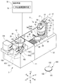
図1に示す本実施形態にかかる加工装置である研削装置1は、ウェーハ100に対して、搬入処理、研削処理、洗浄処理および搬出処理を含む一連の処理を実施するように構成されている。
[Embodiment 1]
The grinding device 1 which is the processing device according to the present embodiment shown in FIG. 1 is configured to perform a series of processes including a carry-in process, a grinding process, a cleaning process, and a carry-out process on the
図1に示すウェーハ100は、被加工物の一例であり、たとえば、円形の半導体ウェーハである。ウェーハ100の表面101には、図示しないデバイスが形成されている。ウェーハ100の表面101は、図1においては下方を向いており、保護テープ103が貼着されることによって保護されている。ウェーハ100の裏面102は、研削処理が施される被研削面である。
The
研削装置1は、略矩形の第1の装置ベース11、第1の装置ベース11の後方(+Y方向側)に連結された第2の装置ベース12、および、上方に延びるコラム13、を備えている。
The grinding device 1 includes a substantially rectangular
第1の装置ベース11の正面側(−Y方向側)には、第2のカセットステージ152が設けられている。第2のカセットステージ152には、加工後のウェーハ100が収容される第2のカセット154が載置されている。また、第2のカセットステージ152の+X側には、第2のカセットステージ152に隣接して、第1のカセットステージ151が取り付けられている。第1のカセットステージ151には、加工前のウェーハ100が収容される第1のカセット153が載置されている。
A
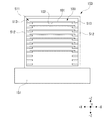
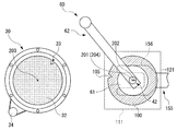
図2に、第1のカセット153を、+Y方向から示す。図2に示すように、第1のカセット153は、+Y方向に向く開口511を有している。また、第1のカセット153は、その内部に、上下方向であるZ軸方向に所定の間隔をあけて配置された、複数の棚513を備えている。棚513は、第1のカセット153の側壁512の内面に形成されている。棚513は、その中央領域が円形状または矩形状に切り欠かれた平板から構成されている。したがって、各棚513は、1枚のウェーハ100を、その外周領域を支持した状態で収容する。また、第2のカセット154も、第1のカセット153と同様の構成を有している。
なお、図2に示す例では、ウェーハ100は、その裏面102が下を向くように、第1のカセット153に収容されている。
FIG. 2 shows the
In the example shown in FIG. 2, the
また、図1に示すように、第1のカセット153および第2のカセット154の+Y方向側には、ロボット155が配設されている。
Further, as shown in FIG. 1, a
ロボット155は、搬送手段の一例であり、第1のカセット153に収納されたウェーハ100を保持するロボットハンド156を装着している。ロボット155は、ロボットハンド156に保持されたウェーハ100を搬送する。ロボットハンド156は、ウェーハ100を吸着保持するための吸着面を備えている。
The
また、ロボット155は、ロボットハンド156を駆動する駆動部157を有している。駆動部157は、ロボットハンド156の位置を制御(調整)する。詳細には、駆動部157は、上下移動手段158および水平移動手段159を備えている。上下移動手段158は、ロボットハンド156をZ軸方向に沿って上下方向に移動させる。水平移動手段159は、ロボットハンド156を水平方向に移動させる。
Further, the
ロボット155は、ロボットハンド156に保持された加工後のウェーハ100を、第2のカセット154に搬入する。また、ロボット155は、ロボットハンド156によって、第1のカセット153の棚513に収容されている加工前のウェーハ100を、裏面102を吸着するように保持し、第1のカセット153から取り出す。さらに、ロボット155は、ウェーハ100の裏面102が上向きとなるように、ロボットハンド156を反転させる。その後、ロボット155は、ウェーハ100を、ロボット155の+Y側に配置されているチャックテーブル30上に搬送する。そして、ロボット155は、チャックテーブル30の保持面32に、裏面102を上にして、ウェーハ100を載置する。
The
第2の装置ベース12の上面側には、開口部14が設けられている。そして、開口部14内には、チャックテーブル30が配置されている。チャックテーブル30は、保持面32によってウェーハ100を保持するように構成されている。保持面32は、吸引源(図示せず)に連通されており、保護テープ103を介してウェーハ100を吸引保持する。チャックテーブル30は、回転手段としてのモータ34(図12参照)により、保持面32によってウェーハ100を保持した状態で、保持面32の中心を通るZ軸方向に延在する中心軸を中心として回転可能である。
An
チャックテーブル30の周囲は、カバー39によって囲まれている。このカバー39には、Y軸方向に伸縮する蛇腹カバー40が連結されている。そして、カバー39および蛇腹カバー40の下方には、図示しないY軸方向移動手段が配設されている。チャックテーブル30は、このY軸方向移動手段によって、Y軸方向に往復移動することが可能となっている。
The circumference of the chuck table 30 is surrounded by a
本実施形態では、チャックテーブル30は、大まかにいえば、保持面32にウェーハ100を載置するための−Y方向側のウェーハ載置領域と、ウェーハ100が研削される+Y方向側の研削領域との間を移動する。
In the present embodiment, roughly speaking, the chuck table 30 has a wafer mounting area on the −Y direction side for mounting the
第2の装置ベース12上の後方(+Y方向側)には、コラム13が立設されている。コラム13の前面には、ウェーハ100を研削する研削手段5、および、研削手段5を研削送り方向であるZ軸方向に移動させる研削送り手段2が設けられている。
A
研削送り手段2は、Z軸方向に平行な一対のZ軸ガイドレール21、このZ軸ガイドレール21上をスライドするZ軸移動テーブル23、Z軸ガイドレール21と平行なZ軸ボールネジ20、Z軸サーボモータ22、および、Z軸移動テーブル23の前面(表面)に取り付けられたホルダ24を備えている。ホルダ24は、研削手段5を保持している。
The grinding feed means 2 includes a pair of Z-axis guide rails 21 parallel to the Z-axis direction, a Z-axis moving table 23 sliding on the Z-axis guide rails 21, and a Z-axis ball screw 20 parallel to the Z-axis guide rails 21, Z. It includes an
Z軸移動テーブル23は、Z軸ガイドレール21にスライド可能に設置されている。図示しないナット部が、Z軸移動テーブル23の後面側(裏面側)に固定されている。このナット部には、Z軸ボールネジ20が螺合されている。Z軸サーボモータ22は、Z軸ボールネジ20の一端部に連結されている。
The Z-axis moving table 23 is slidably installed on the Z-
研削送り手段2では、Z軸サーボモータ22がZ軸ボールネジ20を回転させることにより、Z軸移動テーブル23が、Z軸ガイドレール21に沿って、Z軸方向に移動する。これにより、Z軸移動テーブル23に取り付けられたホルダ24、および、ホルダ24に保持された研削手段5も、Z軸移動テーブル23とともにZ軸方向に移動する。
In the grinding feed means 2, the Z-
研削手段5は、加工手段の一例であり、チャックテーブル30に保持されたウェーハ100を加工する。研削手段5は、ホルダ24に固定されたスピンドルハウジング51、スピンドルハウジング51に回転可能に保持されたスピンドル50、スピンドル50を回転駆動するモータ52、スピンドル50の下端に取り付けられたホイールマウント53、および、ホイールマウント53に支持された研削ホイール54を備えている。
The grinding means 5 is an example of a processing means, and processes the
スピンドルハウジング51は、Z軸方向に延びるようにホルダ24に保持されている。スピンドル50は、チャックテーブル30の保持面32と直交するようにZ軸方向に延び、スピンドルハウジング51に回転可能に支持されている。
The
モータ52は、スピンドル50の上端側に連結されている。このモータ52により、スピンドル50は、Z軸方向に延びる回転軸を中心として回転する。
The
ホイールマウント53は、円板状に形成されており、スピンドル50の下端(先端)に固定されている。ホイールマウント53は、研削ホイール54を支持する。
The
研削ホイール54は、ホイールマウント53と略同径を有するように形成されている。研削ホイール54は、ステンレス等の金属材料から形成された円環状のホイール基台(環状基台)540を含む。ホイール基台540の下面には、全周にわたって、環状に配置された複数の研削砥石541が固定されている。研削砥石541は、チャックテーブル30に保持されたウェーハ100の裏面102を研削する。
The grinding
チャックテーブル30に隣接する位置には、厚み測定器38が配設されている。厚み測定器38は、研削中に、ウェーハ100の厚みを、たとえば接触式にて測定することができる。
A
研削後のウェーハ100は、ロボット155によって搬出される。すなわち、ロボット155は、チャックテーブル30に載置されている研削処理後のウェーハ100の裏面102を吸引保持し、チャックテーブル30から搬出して、枚葉式のスピンナ洗浄ユニット26のスピンナテーブル27に搬送する。
The
スピンナ洗浄ユニット26は、スピンナ洗浄手段の一例である。スピンナ洗浄ユニット26は、ウェーハ100を保持するスピンナテーブル27、および、スピンナテーブル27に向けて洗浄水を噴射するノズル25を備えている。
The
スピンナ洗浄ユニット26では、図示しない回転機構によって、スピンナテーブル27が高速回転される。それとともに、スピンナテーブル27に保持されているウェーハ100の裏面102に向けて洗浄水が噴射されて、ウェーハ100の裏面102がスピンナ洗浄される。その後、ウェーハ100に乾燥エアが吹き付けられて、ウェーハ100が乾燥される。
In the
スピンナ洗浄ユニット26によってウェーハ100が洗浄された後、ロボット155は、ロボットハンド156によって、スピンナテーブル27に保持されているウェーハ100を吸引保持し、スピンナ洗浄ユニット26から搬出して、第2のカセット154に搬入する。
After the
また、ロボット155の上方には、第1カメラ41が設置されている。第1カメラ41は、撮像手段の一例であり、ロボット155のロボットハンド156によって保持されているウェーハ100を撮像する。
A
また、研削装置1は、研削装置1の各部材を制御する制御手段70を備えている。制御手段70は、上述した研削装置1の各部材を制御して、ウェーハ100に対して、作業者の所望する研削加工を実施する。また、制御手段70は、中心座標認識手段72を備えている。
Further, the grinding device 1 includes a control means 70 for controlling each member of the grinding device 1. The control means 70 controls each member of the above-mentioned grinding device 1 to perform the grinding process desired by the operator on the
以下に、中心座標認識手段72の機能とともに、制御手段70によって制御される研削装置1の動作について説明する。 The operation of the grinding device 1 controlled by the control means 70 will be described below along with the functions of the center coordinate recognition means 72.
本実施形態では、制御手段70は、ロボット155を制御して、ロボットハンド156によって、第1のカセット153に収容されているウェーハ100を、裏面102を吸着するように保持し、第1のカセット153から取り出す。その後、制御手段70は、第1カメラ41によって、図3に示すように、ロボットハンド156に保持されているウェーハ100を撮像する。
In the present embodiment, the control means 70 controls the
図3に示すように、ロボットハンド156の中心202を通る直線302と、ロボットハンド156に保持されているウェーハ100の中心201を通る直線301とは、ずれていることがある。
ロボット155は、ウェーハ100を保持した後、ロボットハンド156の中心202を通る直線302上に第1カメラ41が配置されるように、水平移動手段159によってロボットハンド156が移動されるように構成されている。この状態で、第1カメラ41は、ロボットハンド156に保持されたウェーハ100を撮像する。これにより、図4に示すような撮像エリア110に対応する撮像画が取得される。
As shown in FIG. 3, the
After holding the
そして、制御手段70の中心座標認識手段72が、第1カメラ41による撮像によって取得された撮像画に基づいて、ウェーハ100の中心201の座標である中心座標を認識する。
たとえば、中心座標認識手段72は、撮像画からウェーハ100の外周における3点の座標を取得し、これら3点の座標に基づいて、ウェーハ100の中心201の座標である中心座標を取得する。
Then, the center coordinate recognizing
For example, the center coordinate recognizing
制御手段70は、撮像時におけるロボットハンド156の中心202の座標を、予め認識している。そして、制御手段70は、中心座標認識手段72によって取得されたウェーハ100の中心座標に基づいて、ロボットハンド156の中心202とウェーハ100の中心201との位置関係(ずれの量および方向)を算出する。
The control means 70 recognizes in advance the coordinates of the
その後、制御手段70は、ウェーハ100が下側に配置される(ウェーハ100の裏面102が上向きとなる)ように、ロボットハンド156を反転させる。そして、制御手段70は、中心座標認識手段72により認識されたウェーハ100の中心座標に基づいて、ロボット155を制御して、ロボットハンド156によって保持されているウェーハ100の中心201と、チャックテーブル30の保持面32の中心とが一致するように、保持面32にウェーハ100を保持させる。
After that, the control means 70 inverts the
すなわち、研削装置1では、ウェーハ100を保持しているロボットハンド156は、初期設定において、図5に示すように、その中心202を通る直線302と、チャックテーブル30の保持面32の中心203を通る直線303とが一致するように、チャックテーブル30に向けて移動するように構成されている。
That is, in the grinding device 1, in the initial setting, the
このようにロボットハンド156が移動された後、制御手段70は、上記のように算出したロボットハンド156の中心202とウェーハ100の中心201との位置関係(ずれの量および方向)に基づいてロボット155の水平移動手段159を制御して、図6に示すように、ウェーハ100の中心201を通る直線301と、保持面32の中心203を通る直線303とが一致するように、ロボットハンド156の水平方向における位置を、僅かに調整する。この図に示す例では、制御手段70は、ロボットハンド156を、矢印120の方向に僅かにずらす。
After the
その後、制御手段70は、ロボット155の上下移動手段158を制御して、ロボットハンド156を降下させて、ウェーハ100を保持面32に受け渡し、保持させる。これにより、ウェーハ100の中心201と、チャックテーブル30の保持面32の中心203とが一致した状態で、保持面32によってウェーハ100を保持することができる。
After that, the control means 70 controls the vertical movement means 158 of the
以上のように、本実施形態では、制御手段70が、中心座標認識手段72により認識されたウェーハ100の中心座標に基づいて、ロボット155を制御して、ロボット155によって保持されているウェーハ100の中心201と、チャックテーブル30の保持面32の中心203とが一致するように、保持面32にウェーハ100を保持させている。このように、本実施形態では、仮置きテーブルを用いることなく、保持面32にウェーハ100を適切に保持させることができる。したがって、仮置きテーブルを用いない分だけ、ウェーハ100を持ち替える回数を減らせるので、ウェーハ100にゴミが付着して汚染されたりウェーハ100が破損したりするリスクを少なくすることができるとともに、ウェーハ100を第1のカセット153から取り出して保持面32に載置するまでの時間を低減することが可能となる。
なお、ロボットハンド156を撮像する第1カメラ41は、ロボットハンド156の上に配置されていてもよいし、下に配置されていてもよい。
As described above, in the present embodiment, the control means 70 controls the
The
[実施形態2]
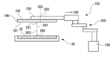
図7に示すように、本実施形態にかかる加工装置である研削装置10は、図1に示した研削装置1の構成において、搬入機構60および搬出機構65をさらに有しているとともに、第1カメラ41に代えて第2カメラ42を備えている。
なお、第1カメラ41と、第2カメラ42との両方を備えていてもよい。
なお、第1カメラ41は、スピンナテーブル27からロボットハンド156が受け取ったウェーハ100の中心と、ロボットハンド156の中心との位置関係を認識するのに用いて、カセットにウェーハ100を収納できないくらいウェーハ100がずれていたら作業者に通知するようにしてもよい。
また、研削装置10では、制御手段70が、中心座標認識手段72に加えて、マーク認識手段73およびマーク位置合わせ制御手段74を備えている。
[Embodiment 2]
As shown in FIG. 7, the grinding
Both the
The
Further, in the grinding
搬入機構60は、ロボット155とともに搬送手段を構成する。搬入機構60は、ロボットハンド156に保持されたウェーハ100を受け取り、チャックテーブル30の保持面32に搬入する。
搬入機構60は、搬送パッド61、および、搬送パッド61を水平方向および上下方向に移動させる移動手段62を有している。搬入機構60は、ロボット155に保持されているウェーハ100を、搬送パッド61によって吸引保持して、チャックテーブル30に搬送し、その保持面32に、裏面102を上にして載置する。
The carry-in
The carry-in
また、研削装置10では、研削後のウェーハ100は、搬出機構65によって、チャックテーブル30の保持面32から搬出される。搬出機構65は、搬出パッド66、および、搬出パッド66を水平方向および上下方向に移動させる移動手段67を有している。搬出機構65は、保持面32に載置されている研削処理後のウェーハ100の裏面102を、搬出パッド66によって吸引保持し、チャックテーブル30から搬出して、枚葉式のスピンナ洗浄ユニット26のスピンナテーブル27に搬送する。
Further, in the grinding
第2カメラ42は、ロボット155と搬入機構60との間の上方に、支持柱43を介して配置されている。第2カメラ42は、撮像手段の一例であり、ロボット155によって保持されているウェーハ100を撮像する。
以下に、マーク認識手段73およびマーク位置合わせ制御手段74の機能とともに、制御手段70によって制御される研削装置10の動作について説明する。
The
Hereinafter, the functions of the mark recognition means 73 and the mark alignment control means 74, as well as the operation of the grinding
本実施形態では、ウェーハ100は、たとえば表面101が下を向くように、第1のカセット153(図2参照)に収容されている。制御手段70は、ロボット155を制御して、ロボットハンド156によって、第1のカセット153の棚513に収容されている加工前のウェーハ100を、表面101を吸着するように保持し、第1のカセット153から取り出す。その後、制御手段70は、第2カメラ42によって、図8に示すように、ロボットハンド156によって保持されているウェーハ100を撮像する。
In this embodiment, the
なお、本実施形態においても、図8に示すように、ロボットハンド156の中心202を通る直線302と、ロボットハンド156に保持されているウェーハ100の中心201を通る直線301とは、ずれていることがある。
ロボット155は、ウェーハ100を保持した後、ロボットハンド156の中心202を通る直線302上に第2カメラ42が配置されるように、水平移動手段159によってロボットハンド156が移動されるように構成されている。この状態で、第2カメラ42は、ロボットハンド156に保持されたウェーハ100を撮像する。これにより、図9に示すような撮像エリア111に対応する撮像画が取得される。
Also in this embodiment, as shown in FIG. 8, the
After holding the
そして、制御手段70の中心座標認識手段72が、第2カメラ42による撮像によって取得された撮像画に基づいて、ウェーハ100の中心201の座標である中心座標を、たとえば、実施形態1に示した方法と同様の方法により認識する。
Then, the center coordinate recognition means 72 of the control means 70 shows the center coordinates, which are the coordinates of the
制御手段70は、撮像時におけるロボットハンド156の中心202の座標を、予め認識している。そして、制御手段70は、中心座標認識手段72によって取得されたウェーハ100の中心座標に基づいて、ロボットハンド156の中心202とウェーハ100の中心201との位置関係(ずれの量および方向)を算出する。
The control means 70 recognizes in advance the coordinates of the
その後、制御手段70は、中心座標認識手段72により認識されたウェーハ100の中心座標に基づいて、搬入機構60によって、保持面32の中心203とウェーハ100の中心201とが一致するように、保持面32にウェーハ100を保持させる。
After that, the control means 70 holds the
すなわち、まず、制御手段70は、搬入機構60の移動手段62を制御して、搬送パッド61を、ロボット155のロボットハンド156上に配置する。搬送パッド61は、図10に示すように、ロボットハンド156の中心202を通る直線302と、搬入機構60の搬送パッド61の中心204を通る直線304とが一致するように、ロボット155上に配置されるように構成されている。
That is, first, the control means 70 controls the moving means 62 of the carry-in
このように搬送パッド61が配置された後、制御手段70は、上記のように算出したロボットハンド156の中心202とウェーハ100の中心201との位置関係(ずれの量および方向)に基づいてロボット155の水平移動手段159を制御して、図11に示すように、ウェーハ100の中心201を通る直線301と、搬送パッド61の中心204を通る直線304とが一致するように、ロボットハンド156の水平方向における位置を、僅かに調整する。この図に示す例では、制御手段70は、ロボットハンド156を、矢印121の方向に僅かにずらす。
After the
その後、制御手段70は、たとえば搬入機構60の移動手段62を制御して搬送パッド61を降下させて、ロボットハンド156上のウェーハ100を、搬送パッド61に受け渡して保持させる。これにより、ウェーハ100の中心201と、搬送パッド61の中心204とが一致した状態で、搬送パッド61によってウェーハ100を保持することができる。
After that, the control means 70 controls, for example, the moving means 62 of the carry-in
その後、制御手段70は、搬入機構60の移動手段62を制御して、ウェーハ100を保持している搬送パッド61を移動させ、チャックテーブル30の保持面32上に配置する。搬送パッド61は、搬送パッド61の中心204を通る直線304と、チャックテーブル30の保持面32の中心203を通る直線303(図6参照)とが一致するように、チャックテーブル30に向けて移動するように構成されている。
After that, the control means 70 controls the moving means 62 of the carry-in
したがって、制御手段70は、この状態で、搬入機構60の移動手段62を制御して、搬送パッド61を降下させて、ウェーハ100を保持面32に受け渡して保持させることにより、ウェーハ100の中心201と、チャックテーブル30の保持面32の中心203とが一致した状態で、保持面32によってウェーハ100を保持することができる。
Therefore, in this state, the control means 70 controls the moving means 62 of the carry-in
以上のように、本実施形態では、制御手段70が、中心座標認識手段72により認識されたウェーハ100の中心座標に基づいて、ロボット155から搬入機構60にウェーハ100を受け渡す。そして、制御手段70が、搬入機構60によって、保持面32の中心203とウェーハ100の中心201とが一致するように、保持面32にウェーハ100を保持させる。したがって、本実施形態でも、仮置きテーブルを用いることなく、保持面32にウェーハ100を適切に保持させることができる。したがって、ウェーハ100の汚染および破損のリスク、および、ウェーハ100を保持面32に保持させるまでにかかる時間を低減することができる。
As described above, in the present embodiment, the control means 70 delivers the
なお、ウェーハ100は、その結晶方位を示すマークとしてのノッチまたはオリエンテーションフラットを備えている場合もある。この場合、本実施形態では、保持面32によって、ウェーハ100を、そのマークに対応する向きに保持することができる。
The
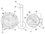
図12に示す例では、ロボット155のロボットハンド156によって保持されているウェーハ100に、ノッチ105が備えられている。また、チャックテーブル30の保持面32は、ウェーハ100を転写した形状を有しており、ノッチ105に対応する形状のマーク対応部33を備えている。
In the example shown in FIG. 12, the
この場合も、第2カメラ42により、図12に示すような撮像エリア111に対応する撮像画が取得され、制御手段70の中心座標認識手段72(図7参照)が、上記したようにウェーハ100の中心201の座標を取得する。さらに、制御手段70のマーク認識手段73が、撮像画に基づいて、ウェーハ100のノッチ105の位置(座標)を認識する。
In this case as well, the
その後、図13に示すように、制御手段70は、上述した手法により、ウェーハ100の中心201と、搬送パッド61の中心204とが一致した状態で、搬送パッド61によってウェーハ100を保持する。さらに、制御手段70は、図14に示すように、ロボット155を退避させる。
After that, as shown in FIG. 13, the control means 70 holds the
次に、制御手段70のマーク位置合わせ制御手段74(図7参照)が、マーク認識手段73によって認識されたノッチ105の位置に基づいて、保持面32のマーク対応部33と、搬送パッド61によって保持されているウェーハ100のノッチ105とを一致させるように、チャックテーブル30を回転させるモータ34を制御する。すなわち、マーク位置合わせ制御手段74は、搬送パッド61によって保持面32に搬送されたウェーハ100のノッチ105の位置に、保持面32のマーク対応部33が配置されるように、モータ34を制御して、チャックテーブル30を回転させる。
Next, the mark alignment control means 74 (see FIG. 7) of the control means 70 is subjected to the
これにより、制御手段70は、ウェーハ100の中心201と、チャックテーブル30の保持面32の中心203とが一致した状態であって、かつ、図15に示すように、ウェーハ100のノッチ105と保持面32のマーク対応部33とが一致した状態で、保持面32によってウェーハ100を保持することができる。
As a result, the control means 70 holds the
なお、図1に示した研削装置1においても、制御手段70が、図7に示したマーク認識手段73およびマーク位置合わせ制御手段74を備えるとともに、保持面32がマーク対応部33を備えてもよい。そして、制御手段70が、ウェーハ100の中心201と、チャックテーブル30の保持面32の中心203とが一致した状態、かつ、ウェーハ100のノッチ105と保持面32のマーク対応部33とが一致した状態で、保持面32にウェーハ100を保持させてもよい。
Even in the grinding device 1 shown in FIG. 1, the control means 70 includes the mark recognition means 73 and the mark alignment control means 74 shown in FIG. 7, and the holding
また、ウェーハ100が、ノッチ105に代えてオリエンテーションフラットを有している場合もある。この場合、チャックテーブル30の保持面32は、たとえば、ウェーハ100を保持する際、そのオリエンテーションフラットに対応する部分からの吸引を切断するように構成される。
すなわち、この構成では、保持面32におけるウェーハ100を吸引する部分が、ウェーハ100を転写した形状を有する。そして、保持面32における吸引が切断される部分が、オリエンテーションフラットに対応したマーク対応部となる。マーク位置合わせ制御手段74は、搬送パッド61によって保持面32に搬送されたウェーハ100のオリエンテーションフラットの位置に、保持面32における吸引が切断される部分が配置されるように、モータ34を制御して、チャックテーブル30を回転させる。
Further, the
That is, in this configuration, the portion of the holding
また、実施形態1および2にかかる技術は、研削装置1および研削装置10に限らず、被加工物を搬送手段によってチャックテーブルに搬送する加工装置全般に対して、好適に適用することができる。
Further, the techniques according to the first and second embodiments can be suitably applied not only to the grinding device 1 and the grinding
1:研削装置、10:研削装置、
151:第1のカセットステージ、153:第1のカセット、
155:ロボット、156:ロボットハンド、
157:駆動部、158:上下移動手段、159:水平移動手段、
60:搬入機構、61:搬送パッド、62:移動手段、
30:チャックテーブル、32:保持面、33:マーク対応部、34:モータ、
65:搬出機構、66:搬出パッド、67:移動手段、
70:制御手段、72:中心座標認識手段、
73:マーク認識手段、74:マーク位置合わせ制御手段、
41:第1カメラ、42:第2カメラ、110:撮像エリア、111:撮像エリア、
100:ウェーハ、101:表面、102:裏面、105:ノッチ
1: Grinding device, 10: Grinding device,
151: First cassette stage, 153: First cassette,
155: Robot, 156: Robot hand,
157: Drive unit, 158: Vertical moving means, 159: Horizontal moving means,
60: Carry-in mechanism, 61: Transport pad, 62: Transportation means,
30: Chuck table, 32: Holding surface, 33: Mark corresponding part, 34: Motor,
65: Carry-out mechanism, 66: Carry-out pad, 67: Transportation means,
70: Control means, 72: Center coordinate recognition means,
73: Mark recognition means, 74: Mark alignment control means,
41: 1st camera, 42: 2nd camera, 110: imaging area, 111: imaging area,
100: Wafer, 101: Front side, 102: Back side, 105: Notch
Claims (3)
該搬送手段によって保持されている被加工物を撮像する撮像手段と、
該撮像手段による撮像によって取得された撮像画に基づいて、被加工物の中心座標を認識する中心座標認識手段と、
該中心座標認識手段により認識された該中心座標に基づいて、該搬送手段を制御して、該搬送手段によって保持されている被加工物の中心と、該チャックテーブルの該保持面の中心とが一致するように、該保持面に被加工物を保持させる制御手段と、をさらに備える、
加工装置。 A cassette having a plurality of shelves arranged in the vertical direction, a cassette stage on which the cassette is placed, a chuck table for holding a work piece by a holding surface, and a work piece stored in the cassette are held. A processing apparatus including a transporting means for transporting a work piece from the cassette to the chuck table and a processing means for processing the work piece held on the chuck table.
An image pickup means for imaging a work piece held by the transport means, and an image pickup means.
A center coordinate recognizing means for recognizing the center coordinates of the workpiece based on the image captured by the imaging by the imaging means, and
Based on the center coordinates recognized by the center coordinate recognizing means, the transport means is controlled so that the center of the workpiece held by the transport means and the center of the holding surface of the chuck table are aligned with each other. A control means for holding the workpiece on the holding surface so as to match is further provided.
Processing equipment.
該撮像手段は、該ロボットハンドに保持された被加工物を撮像し、
該制御手段は、該中心座標認識手段によって認識された該中心座標に基づいて、該搬入機構によって、該保持面の中心と被加工物の中心とが一致するように、該保持面に被加工物を保持させる、
請求項1記載の加工装置。 The transport means receives a robot equipped with a robot hand that holds a work piece stored in the cassette and a work piece held by the robot hand, and carries the work piece onto the holding surface of the chuck table. With and
The imaging means captures an image of the workpiece held by the robot hand.
Based on the center coordinates recognized by the center coordinate recognizing means, the control means processes the holding surface so that the center of the holding surface and the center of the workpiece coincide with each other by the carry-in mechanism. Hold things,
The processing apparatus according to claim 1.
該保持面は、被加工物を転写した形状を有し、該マークに対応したマーク対応部を備えており、
該撮像手段による撮像によって得られた該撮像画から該マークの位置を認識するマーク認識手段と、
該保持面の中心を軸に該チャックテーブルを回転させる回転手段と、
該保持面の該マーク対応部と、該搬送手段によって保持されている被加工物の該マークとを一致させるように、該回転手段を制御する、マーク位置合わせ制御手段と、をさらに備える、
請求項1記載の加工装置。 The work piece has a notch or orientation flat as a mark indicating the crystal orientation.
The holding surface has a shape obtained by transferring the workpiece, and is provided with a mark-corresponding portion corresponding to the mark.
A mark recognition means that recognizes the position of the mark from the image obtained by imaging by the image pickup means,
A rotating means for rotating the chuck table around the center of the holding surface, and
A mark alignment control means for controlling the rotation means so as to match the mark corresponding portion of the holding surface with the mark of the workpiece held by the transport means is further provided.
The processing apparatus according to claim 1.
Priority Applications (4)
| Application Number | Priority Date | Filing Date | Title |
|---|---|---|---|
| JP2020005230A JP2021114493A (en) | 2020-01-16 | 2020-01-16 | Processing device |
| TW109147200A TW202128349A (en) | 2020-01-16 | 2020-12-31 | Processing device capable of reducing the number of transferring and holding a workpiece when transporting the workpiece to a chuck table |
| KR1020210001337A KR20210092683A (en) | 2020-01-16 | 2021-01-06 | Machining apparatus |
| CN202110036686.XA CN113199353A (en) | 2020-01-16 | 2021-01-12 | Processing device |
Applications Claiming Priority (1)
| Application Number | Priority Date | Filing Date | Title |
|---|---|---|---|
| JP2020005230A JP2021114493A (en) | 2020-01-16 | 2020-01-16 | Processing device |
Publications (1)
| Publication Number | Publication Date |
|---|---|
| JP2021114493A true JP2021114493A (en) | 2021-08-05 |
Family
ID=77025179
Family Applications (1)
| Application Number | Title | Priority Date | Filing Date |
|---|---|---|---|
| JP2020005230A Pending JP2021114493A (en) | 2020-01-16 | 2020-01-16 | Processing device |
Country Status (4)
| Country | Link |
|---|---|
| JP (1) | JP2021114493A (en) |
| KR (1) | KR20210092683A (en) |
| CN (1) | CN113199353A (en) |
| TW (1) | TW202128349A (en) |
Cited By (1)
| Publication number | Priority date | Publication date | Assignee | Title |
|---|---|---|---|---|
| WO2023026917A1 (en) * | 2021-08-24 | 2023-03-02 | 川崎重工業株式会社 | Substrate transport robot and control method for substrate transport robot |
Family Cites Families (8)
| Publication number | Priority date | Publication date | Assignee | Title |
|---|---|---|---|---|
| JP2008183659A (en) * | 2007-01-30 | 2008-08-14 | Disco Abrasive Syst Ltd | Grinder |
| JP2009123790A (en) * | 2007-11-13 | 2009-06-04 | Disco Abrasive Syst Ltd | Grinding device |
| JP6192527B2 (en) * | 2013-12-18 | 2017-09-06 | 株式会社ディスコ | Grinding equipment |
| JP2015217449A (en) * | 2014-05-14 | 2015-12-07 | 株式会社ディスコ | Grinding device |
| JP6415349B2 (en) * | 2015-02-20 | 2018-10-31 | 株式会社ディスコ | Wafer alignment method |
| JP6970492B2 (en) | 2016-08-18 | 2021-11-24 | 株式会社ディスコ | Grinding device |
| JP6721468B2 (en) * | 2016-09-14 | 2020-07-15 | 株式会社ディスコ | Processing equipment |
| JP7002295B2 (en) | 2017-11-09 | 2022-01-20 | 株式会社ディスコ | Processing method and processing equipment for plate-shaped workpieces |
-
2020
- 2020-01-16 JP JP2020005230A patent/JP2021114493A/en active Pending
- 2020-12-31 TW TW109147200A patent/TW202128349A/en unknown
-
2021
- 2021-01-06 KR KR1020210001337A patent/KR20210092683A/en active Search and Examination
- 2021-01-12 CN CN202110036686.XA patent/CN113199353A/en active Pending
Cited By (1)
| Publication number | Priority date | Publication date | Assignee | Title |
|---|---|---|---|---|
| WO2023026917A1 (en) * | 2021-08-24 | 2023-03-02 | 川崎重工業株式会社 | Substrate transport robot and control method for substrate transport robot |
Also Published As
| Publication number | Publication date |
|---|---|
| TW202128349A (en) | 2021-08-01 |
| CN113199353A (en) | 2021-08-03 |
| KR20210092683A (en) | 2021-07-26 |
Similar Documents
| Publication | Publication Date | Title |
|---|---|---|
| JP6679157B2 (en) | Transfer mechanism of processing equipment | |
| JP2009123790A (en) | Grinding device | |
| JP2010186863A (en) | Aligning mechanism, working device and aligning method | |
| JP2009533849A (en) | Method and apparatus for placing electronic components, in particular semiconductor chips, on a substrate | |
| JP2009255214A (en) | Machining apparatus | |
| JP5117686B2 (en) | Grinding equipment | |
| JP6202962B2 (en) | Cutting equipment | |
| JP5930519B2 (en) | Processing equipment | |
| JP2014038929A (en) | Inline system | |
| JP6415349B2 (en) | Wafer alignment method | |
| JP2021114493A (en) | Processing device | |
| JP2009135254A (en) | Method of sticking adhesive tape | |
| CN113246324A (en) | Cutting device and cutting method | |
| JP5723563B2 (en) | Alignment method | |
| JP2009206362A (en) | Method of cutting plate-like material | |
| JP6192526B2 (en) | Processing equipment | |
| JP6574373B2 (en) | Disc-shaped workpiece grinding method | |
| JP2012175022A (en) | Wafer processing device | |
| JP6208587B2 (en) | Cutting equipment | |
| TWI813837B (en) | touch panel | |
| JP2018032825A (en) | Alignment method for work piece | |
| KR20210104558A (en) | Machining apparatus | |
| JP5473715B2 (en) | Adjustment method of wafer transfer mechanism | |
| JP7320425B2 (en) | cleaning equipment | |
| JP2021074787A (en) | Machining device |
Legal Events
| Date | Code | Title | Description |
|---|---|---|---|
| A521 | Request for written amendment filed |
Free format text: JAPANESE INTERMEDIATE CODE: A523 Effective date: 20200409 |
|
| A521 | Request for written amendment filed |
Free format text: JAPANESE INTERMEDIATE CODE: A821 Effective date: 20200409 |
|
| A621 | Written request for application examination |
Free format text: JAPANESE INTERMEDIATE CODE: A621 Effective date: 20221125 |
|
| A977 | Report on retrieval |
Free format text: JAPANESE INTERMEDIATE CODE: A971007 Effective date: 20231011 |
|
| A131 | Notification of reasons for refusal |
Free format text: JAPANESE INTERMEDIATE CODE: A131 Effective date: 20231017 |
|
| A521 | Request for written amendment filed |
Free format text: JAPANESE INTERMEDIATE CODE: A523 Effective date: 20231215 |
|
| A131 | Notification of reasons for refusal |
Free format text: JAPANESE INTERMEDIATE CODE: A131 Effective date: 20240312 |