JP2021089399A - Fixed focal lens and design method therefor - Google Patents
Fixed focal lens and design method therefor Download PDFInfo
- Publication number
- JP2021089399A JP2021089399A JP2019220947A JP2019220947A JP2021089399A JP 2021089399 A JP2021089399 A JP 2021089399A JP 2019220947 A JP2019220947 A JP 2019220947A JP 2019220947 A JP2019220947 A JP 2019220947A JP 2021089399 A JP2021089399 A JP 2021089399A
- Authority
- JP
- Japan
- Prior art keywords
- lens
- power
- center
- single focus
- astigmatic
- Prior art date
- Legal status (The legal status is an assumption and is not a legal conclusion. Google has not performed a legal analysis and makes no representation as to the accuracy of the status listed.)
- Granted
Links
- 238000000034 method Methods 0.000 title claims abstract description 10
- 238000013461 design Methods 0.000 title abstract description 24
- 201000009310 astigmatism Diseases 0.000 claims abstract description 86
- 238000012937 correction Methods 0.000 claims abstract description 80
- 230000002093 peripheral effect Effects 0.000 claims description 34
- 210000005252 bulbus oculi Anatomy 0.000 claims description 5
- 230000004438 eyesight Effects 0.000 claims description 5
- 230000003247 decreasing effect Effects 0.000 claims description 2
- 208000003464 asthenopia Diseases 0.000 abstract description 8
- 230000000052 comparative effect Effects 0.000 description 53
- 230000008859 change Effects 0.000 description 33
- 238000009826 distribution Methods 0.000 description 27
- 238000010586 diagram Methods 0.000 description 26
- 230000007423 decrease Effects 0.000 description 14
- 238000004088 simulation Methods 0.000 description 9
- 210000001508 eye Anatomy 0.000 description 8
- 230000004075 alteration Effects 0.000 description 6
- 208000012661 Dyskinesia Diseases 0.000 description 5
- 230000004048 modification Effects 0.000 description 4
- 238000012986 modification Methods 0.000 description 4
- 208000001491 myopia Diseases 0.000 description 4
- 230000002194 synthesizing effect Effects 0.000 description 4
- 230000003867 tiredness Effects 0.000 description 4
- 208000016255 tiredness Diseases 0.000 description 4
- 206010020675 Hypermetropia Diseases 0.000 description 3
- 238000004364 calculation method Methods 0.000 description 3
- 238000005520 cutting process Methods 0.000 description 3
- 230000004305 hyperopia Effects 0.000 description 3
- 201000006318 hyperopia Diseases 0.000 description 3
- 230000006872 improvement Effects 0.000 description 3
- 239000000463 material Substances 0.000 description 3
- 230000004379 myopia Effects 0.000 description 3
- 238000012545 processing Methods 0.000 description 3
- 230000000694 effects Effects 0.000 description 2
- 230000004418 eye rotation Effects 0.000 description 2
- 238000005457 optimization Methods 0.000 description 2
- 230000004304 visual acuity Effects 0.000 description 2
- 241000282461 Canis lupus Species 0.000 description 1
- 206010019233 Headaches Diseases 0.000 description 1
- 230000009471 action Effects 0.000 description 1
- 230000008901 benefit Effects 0.000 description 1
- 239000002131 composite material Substances 0.000 description 1
- 210000004087 cornea Anatomy 0.000 description 1
- 208000002173 dizziness Diseases 0.000 description 1
- 235000012489 doughnuts Nutrition 0.000 description 1
- 230000004064 dysfunction Effects 0.000 description 1
- 238000011156 evaluation Methods 0.000 description 1
- 231100000869 headache Toxicity 0.000 description 1
- 238000012905 input function Methods 0.000 description 1
- 238000012886 linear function Methods 0.000 description 1
- 238000003754 machining Methods 0.000 description 1
- 238000004519 manufacturing process Methods 0.000 description 1
- 239000000203 mixture Substances 0.000 description 1
- 230000003287 optical effect Effects 0.000 description 1
- 238000003672 processing method Methods 0.000 description 1
- 230000009467 reduction Effects 0.000 description 1
- 238000003860 storage Methods 0.000 description 1
- 208000029257 vision disease Diseases 0.000 description 1
- 230000000007 visual effect Effects 0.000 description 1
- 230000004393 visual impairment Effects 0.000 description 1
Images


Landscapes
- Eyeglasses (AREA)
Abstract
Description
本発明は乱視矯正機能のある例えば眼鏡やルーペに使用される単焦点レンズ及びその設計方法に関するものである。 The present invention relates to a single focus lens used for, for example, spectacles and loupes having an astigmatism correction function, and a method for designing the same.
角膜が歪んでいることによって生ずる視覚障害の一つとして乱視がある。乱視とは点光源が、円、楕円あるいは線となって点として結像しないため明視できない状態である。乱視が生じている場合物体が見づらくなったり眼精疲労や頭痛の原因ともなるためごく軽度でない限りこれを矯正することが好ましい。単焦点レンズにおける乱視矯正用レンズを作製する場合の主要な処方データは、S度数とC度数と乱視軸で表される。S度数は球面度数であって、近視や遠視の度合いを示すものである。C度数は乱視の度合いを示すものであり乱視矯正度数となる。乱視は眼球の歪みに起因し、円柱レンズで矯正可能である。実際には円柱レンズを軸方向にカットしたかまぼこ形状のトーリック面として合成されることとなる。また、眼球の歪んでいる方向は人によって区々であるためその歪み方向を示す情報として乱視軸(円柱レンズの軸方向)が設定される。
このような乱視矯正用レンズの一例として特許文献1を示す。
Astigmatism is one of the visual impairments caused by the distortion of the cornea. Astigmatism is a state in which a point light source becomes a circle, an ellipse, or a line and is not imaged as a point, so that it cannot be clearly seen. When astigmatism occurs, it becomes difficult to see the object, and it causes eyestrain and headache. Therefore, it is preferable to correct it unless it is very mild. The main prescription data for producing an astigmatism correction lens in a single focus lens is represented by S power, C power and astigmatism axis. The S power is a spherical power, which indicates the degree of myopia or hyperopia. The C power indicates the degree of astigmatism and is the astigmatism correction power. Astigmatism is caused by distortion of the eyeball and can be corrected with a cylindrical lens. Actually, the cylindrical lens is synthesized as a semi-cylindrical toric surface cut in the axial direction. Further, since the direction in which the eyeball is distorted varies depending on the person, the astigmatic axis (axial direction of the cylindrical lens) is set as information indicating the distorted direction.
乱視が比較的強度であると眼鏡の装用において、乱視を正しく矯正するとかえって眼の疲れや歩く際にふらつきを感じたりすることがある。これは乱視矯正のトーリック面において軸方向となる弱主注視線方向と強主注視線方向との像倍率差が大きくなりすぎて空間の歪みを感ずるからである。そのため、従来では乱視が比較的強度な装用者では眼鏡店の主観やあるいは装用者側の要請等によって測定値よりも弱い乱視矯正量に調整してしまうことがあった。
例えば、
完全矯正度数S−4.00 C−4.00
である場合に、S−4.00 C−3.00というように、乱視矯正量を間引くことが行われている。あるいは、
完全矯正度数S−4.00 C−4.00
である場合に、S−4.50 C−3.00というように、間引く乱視矯正量の半分の度度数を球面度数に加算すること(いわゆる等価球面処方)が行われている。
しかし、いずれの手法も本来の測定値を使用しない矯正であるため、乱視が比較的強度である装用者にとって最適な視力補正手段といえるものではない。また、眼鏡店側においても、どの程度完全矯正度数からずらせば装用者に無理なくより好適な処方となるかを判断することは難しい。
そのため、当該装用者の完全矯正度数を用い、なおかつ装用者が疲れにくく装用して歩く際にふらつきを感じにくい乱視矯正レンズ及びその設計方法が要望されていた。
If the astigmatism is relatively strong, when wearing eyeglasses, if the astigmatism is corrected correctly, the eyes may get tired or the person may feel light-headed when walking. This is because the difference in image magnification between the weak main gaze direction and the strong main gaze direction, which are the axial directions in the toric surface of astigmatism correction, becomes too large, and the distortion of space is felt. Therefore, in the past, a wearer with relatively strong astigmatism may adjust the amount of astigmatism correction to be weaker than the measured value due to the subjectivity of the optician or the request of the wearer.
For example
Complete correction power S-4.00 C-4.00
In this case, the amount of astigmatism correction is thinned out, such as S-4.00 C-3.00. Or
Complete correction power S-4.00 C-4.00
In this case, the dioptric power of half of the astigmatism correction amount to be thinned out is added to the spherical dioptric power (so-called equivalent spherical prescription), such as S-4.50 C-3.00.
However, since all the methods are corrections that do not use the original measured values, they cannot be said to be the most suitable visual acuity correction means for the wearer who has relatively strong astigmatism. In addition, it is difficult for the optician to determine how much the prescription should be deviated from the complete correction power to make the prescription more suitable for the wearer.
Therefore, there has been a demand for an astigmatism correction lens and a design method thereof, which uses the complete correction power of the wearer and does not cause the wearer to feel tired and wobble when walking.
上記課題を解決するために手段1では、乱視矯正のための乱視矯正度数が付加された乱視矯正レンズにおいて、レンズ中心を含むレンズ中央領域で所定の乱視矯正度数が設定され、前記レンズ中央領域からレンズ周辺に向かって前記所定の乱視矯正度数が漸減されているようにした。
これによって、中心付近においては所定の乱視矯正度数が維持されるため、処方された完全矯正度数あるいは完全矯正度数に近い度数での目視が可能となり、一方でレンズ周辺においては弱主注視線方向と強主注視線方向との像倍率差が減少あるいは解消されるため、空間の歪みを感じにくくなって使用時の眼の疲れや歩く際のふらつき感が緩和されることとなる。
In order to solve the above problem, in the
As a result, the predetermined astigmatism correction power is maintained near the center, so that it is possible to visually check at the prescribed complete correction power or a power close to the perfect correction power, while the weak main gaze direction is around the lens. Since the difference in image magnification from the direction of the strong main gaze is reduced or eliminated, it becomes difficult to feel the distortion of the space, and the tiredness of the eyes during use and the feeling of wobbling when walking are alleviated.
「乱視矯正度数が付加された乱視矯正レンズ」は、C度数(乱視矯正度数)が設定されていれば必ずしもS度数(球面度数)が設定されていなくともよい。乱視矯正される面はトーリック面とされる。トーリック面は円を中心を通らない直線を軸として回転させたときに描かれる曲面であって、「タル型」と「ドーナツ型」の二種類がある。トーリック面では縦方向と横(周)方向の曲率が異なるため、所定の縦横の曲率とされたトーリック面を設定することで乱視の矯正とするものである。
「レンズ中心を含むレンズ中央領域」は、装用者が遠用視〜近用視をする領域であり、少なくとも正面を向いて遠用視する領域が含まれる領域であることがよい。
「中央領域からレンズ周辺に向かって前記所定の乱視矯正度数が漸減され」とあるため、中央領域から外側にいくほど乱視矯正度数が緩和されることとなる。
計算においては、S度数、C度数、AX(乱視軸)とおいてもよく、これらをJCC(ジャクソンクロスシリンダー)の標準化したデータに変換して計算してもよい。
レンズの用途として、視力矯正のための眼鏡に使用することのほかに、ツルを有する眼鏡のように手を離して使用できるルーペとすることもよい。ルーペとする場合にはレンズはプラスレンズとなる。
The "astigmatism correction lens to which the astigmatism correction power is added" does not necessarily have to be set to the S power (spherical power) as long as the C power (astigmatism correction power) is set. The surface to be corrected for astigmatism is regarded as the toric surface. The toric surface is a curved surface drawn when rotated around a straight line that does not pass through the center of a circle, and there are two types, a "barrel type" and a "doughnut type". Since the curvatures in the vertical direction and the horizontal (circumferential) direction are different on the toric surface, astigmatism is corrected by setting the toric surface having a predetermined vertical and horizontal curvature.
The “lens center region including the center of the lens” is a region in which the wearer makes a distance vision to a near vision, and may be a region including at least a region facing the front for a distance vision.
Since it is stated that "the predetermined astigmatism correction power is gradually reduced from the central region toward the periphery of the lens", the astigmatism correction power is relaxed toward the outside from the central region.
In the calculation, S power, C power, and AX (astigmatism axis) may be set, and these may be converted into standardized data of JCC (Jackson cross cylinder) and calculated.
In addition to being used for eyeglasses for correcting eyesight, the lens may be used as a loupe that can be used by releasing the hand like eyeglasses having a vine. When using a loupe, the lens is a plus lens.
また、手段2では、レンズ周辺において等価球面となるように前記所定の乱視矯正度数が漸減されているようにした。
これによって、レンズ周辺の全周囲において乱視矯正は低矯正になるものの、球面度数がそれをカバーすることで、比較的良好に屈折補正されることになる。
従来の乱視レンズにおいては、ユーザーの眼の疲れや歩く際のふらつきを防ぐため、乱視を完全矯正せずに等価球面での屈折矯正がなされていた可能性が高い。本発明のレンズにおいては、レンズ中心では乱視を完全矯正するものの、レンズ周辺では、従来の乱視レンズにおける等価球面度数での見え方に近くなり、全体の装用感は保たれ、レンズ中心の視力の向上というメリットのみが享受されることになる。
また、手段3では、前記等価球面は平均度数であるようにした。平均度数についても上記と同様の作用効果が奏される。
Further, in the
As a result, astigmatism correction becomes low in the entire circumference around the lens, but the spherical power covers it, so that the refraction correction is relatively good.
In the conventional astigmatism lens, it is highly possible that the refraction correction on the equivalent spherical surface is performed without completely correcting the astigmatism in order to prevent the user's eyes from getting tired and wobbling when walking. In the lens of the present invention, astigmatism is completely corrected at the center of the lens, but at the periphery of the lens, the appearance is close to that of a conventional astigmatism lens at the equivalent spherical power, the overall wearing feeling is maintained, and the visual acuity at the center of the lens is maintained. Only the benefit of improvement will be enjoyed.
Further, in the means 3, the equivalent spherical surface is set to have an average frequency. The same action and effect as described above are exhibited for the average frequency.
また、手段4では、前記レンズ中央領域は中心から半径15mmよりも内側の領域であるようにした。
中央領域を中心から半径15mmよりも外側の領域までとしてもよいが、半径15mmよりも内側の領域は、特に視線が物体を意識的に注視して鮮明に目視するための領域であり、その領域でユーザーは乱視を正しく矯正した状態でレンズを使用することができ、一方半径15mmの外側は視野の周辺領域となって注視しないため、乱視を正しく矯正しなくともそれほど支障のない領域であるため、乱視矯正度数が漸減されることで、眼の疲れや歩く際のふらつきが抑制されることとなる。
また、手段5では、装用者の眼球が回転するときの仮想的な回転中心から、レンズ裏面中心までの距離を25mmとした条件において、前記レンズの中央から前記レンズ周辺に向けて、視線を30°回旋させたとき、視線が通過するレンズ面での実効屈折力における乱視度数が、レンズ中心の当該装用者の処方値における乱視度数よりも0.25D〜1.00Dの範囲で少なくなっているようにした。
視線を30°回旋させたときの視線が通過するレンズ面は、おおよそ、レンズ中心から15mm地点であるが、これは、さまざまなメガネフレームのうち、「小さめ」と言えるメガネフレームにおいて、レンズ中心から枠までのおおよその最短距離であり、この範囲で、0.25D以上の補正が加われば、ほぼ全てのユーザーのレンズが本発明の効果を享受できるものと想定している。
また、実装評価において、0.75〜1.00D程度の補正でも、度数の変化による違和感はなく、良好な装用状態であることが確認されている。
Further, in the
The central region may be from the center to the region outside the radius of 15 mm, but the region inside the radius of 15 mm is a region in which the line of sight consciously gazes at the object and clearly sees the object. The user can use the lens with the astigmatism corrected correctly, while the outside of the radius of 15 mm is the peripheral area of the visual field and does not gaze, so there is not much trouble even if the astigmatism is not corrected correctly. By gradually reducing the astigmatism correction radius, eye fatigue and wobbling when walking are suppressed.
Further, in the means 5, the line of sight is 30 from the center of the lens toward the periphery of the lens under the condition that the distance from the virtual center of rotation when the wearer's eyeball rotates to the center of the back surface of the lens is 25 mm. When rotated, the astigmatic power of the effective refractive power on the lens surface through which the line of sight passes is less in the range of 0.25D to 1.00D than the astigmatic power of the wearer's prescribed value at the center of the lens. I did it.
The lens surface through which the line of sight passes when the line of sight is rotated by 30 ° is approximately 15 mm from the center of the lens. Among various spectacle frames, this is the "smaller" spectacle frame from the center of the lens. It is an approximate shortest distance to the frame, and it is assumed that almost all users' lenses can enjoy the effect of the present invention if a correction of 0.25D or more is added within this range.
Further, in the mounting evaluation, it has been confirmed that even with a correction of about 0.75 to 1.00D, there is no discomfort due to the change in the power, and the wearing condition is good.
また、手段6では、球面度数がプラスであるようにした。
球面度数がプラスである場合とは、例えば遠視を矯正したり、眼鏡のようなフレームを有し手を使用せずにつるを耳にかけて使用する眼鏡用ルーペである。
また、手段7では、球面度数がマイナスであるようにした。
球面度数がマイナスである場合とは、例えば近視を矯正する場合である。
また、手段8では、球面度数が0であるようにした。
例えば、近視や遠視の度数がなく、乱視度数のみを有するユーザーを想定している。
Further, in the
The case where the spherical power is positive is, for example, a spectacle loupe for correcting hyperopia or having a frame such as spectacles and using the vine over the ear without using a hand.
Further, in the means 7, the spherical power is set to be negative.
The case where the spherical power is negative is, for example, the case where myopia is corrected.
Further, in the
For example, it is assumed that a user has only astigmatic power without myopia or hyperopia.
また、手段9では、レンズ中心を含むレンズ中央領域で所定の乱視矯正度数が設定され、前記レンズ中央領域からレンズ周辺に向かって前記所定の乱視矯正度数が漸減される単焦点レンズの加工方法であって、基準となる球面又は非球面に構成されたベース面に対して、レンズ体の中心を含んでレンズ面に垂直に交わる平面と同レンズ面との交わりによってできる断面曲線の曲率が最大となる方向と最小となる方向が直交又は略直交するような乱視矯正面の曲面と、レンズ中心を含むレンズ中央領域から周縁に向かって前記断面曲線の曲率が均等となる修正面の曲面とを合成するようにした。
これによって、レンズ中心を含むレンズ中央領域で所定の乱視矯正度数が設定され、そのレンズ中央領域からレンズ周辺に向かって、その所定の乱視矯正度数が漸減されるような単焦点レンズを作製することが可能となる。
Further, in the means 9, a predetermined dyskinesia correction power is set in the lens central region including the lens center, and the predetermined dysfunction correction power is gradually reduced from the lens center region toward the periphery of the lens by a processing method of a single focus lens. Therefore, the curvature of the cross-sectional curve formed by the intersection of the plane intersecting the lens surface perpendicularly to the lens surface including the center of the lens body with respect to the base surface formed on the reference spherical or aspherical surface is the maximum. Combining the curved surface of the dyskinesia correction surface such that the direction in which the lens becomes and the direction in which the lens becomes the minimum are orthogonal or substantially orthogonal to each other, and the curved surface of the correction surface in which the curvature of the cross-sectional curve becomes uniform from the central region of the lens including the lens center toward the peripheral edge. I tried to do it.
As a result, a fixed focal length lens is produced in which a predetermined astigmatism correction dioptric power is set in the lens central region including the lens center, and the predetermined astigmatism correction dioptric power is gradually reduced from the lens central region toward the periphery of the lens. Is possible.
この手段9の発想は、球面又は非球面となるレンズ面にトーリック面を組み合わせ、それらの合成された面に更に周縁に向かってトーリック面が緩和される修正面を組み合わせるというものである。但し、合成の順は問わず、加工においても、球面又は非球面→トーリック面→修正面というように順に加工しても、3つのデータを合成した合成データに基づいて同時に加工してもよい。
乱視矯正面において断面曲線の曲率が最小となる方向(つまり乱視軸)と断面曲線の曲率が最大となる方向は直交するよう設計するのが基本である。しかし、実際の装用における乱視矯正能力としては完全に直交していなくとも問題がないため略直交で構わない。より具体的には例えば70〜110度の範囲ならば略直交に含まれ実際の装用には問題はない。
また、レンズ中央領域からレンズ周辺に向かって乱視矯正度数を漸減させる際の形状の変化率については、緩やかにトーリック面が修正され周縁部ではトーリック面がない、あるいは大変緩やかである状態がよい。そのため、変化率は急激にならないように関数の関係が急激になりにくい一次式あるいは二次式で設定することがよい。
本願発明は以下の実施の形態に記載の構成に限定されない。各実施の形態や変形例の構成要素は任意に選択して組み合わせて構成するとよい。また各実施の形態や変形例の任意の構成要素と、発明を解決するための手段に記載の任意の構成要素または発明を解決するための手段に記載の任意の構成要素を具体化した構成要素とは任意に組み合わせて構成するとよい。これらについても本願の補正または分割出願等において権利取得する意思を有する。
また、意匠出願への変更出願により、全体意匠または部分意匠について権利取得する意思を有する。図面は本装置の全体を実線で描画しているが、全体意匠のみならず当該装置の一部の部分に対して請求する部分意匠も包含した図面である。例えば当該装置の一部の部材を部分意匠とすることはもちろんのこと、部材と関係なく当該装置の一部の部分を部分意匠として包含した図面である。当該装置の一部の部分としては、装置の一部の部材とてもよいし、その部材の部分としてもよい。
The idea of this means 9 is to combine a toric surface with a lens surface that becomes a spherical surface or an aspherical surface, and to combine a combined surface with a correction surface in which the toric surface is further relaxed toward the peripheral edge. However, regardless of the order of composition, the processing may be performed in the order of spherical surface or aspherical surface → toric surface → correction surface, or may be processed at the same time based on the composite data obtained by synthesizing the three data.
Basically, the direction in which the curvature of the cross-sectional curve is minimized (that is, the axis of astigmatism) and the direction in which the curvature of the cross-section curve is maximized are orthogonal to each other on the astigmatism correction surface. However, astigmatism correction ability in actual wearing does not have to be completely orthogonal, so that it may be substantially orthogonal. More specifically, for example, if it is in the range of 70 to 110 degrees, it is included substantially orthogonally and there is no problem in actual wearing.
Further, regarding the rate of change in shape when the astigmatism correction power is gradually reduced from the central region of the lens toward the periphery of the lens, it is preferable that the toric surface is gently corrected and there is no toric surface at the peripheral portion or the toric surface is very gentle. Therefore, it is preferable to set the rate of change by a linear expression or a quadratic expression in which the relationship between the functions does not become abrupt so as not to abrupt.
The invention of the present application is not limited to the configuration described in the following embodiments. The components of each embodiment and modification may be arbitrarily selected and combined. Further, any component of each embodiment or modification, and any component described in the means for solving the invention or a component described in the means for solving the invention are embodied. And may be configured in any combination. We also intend to acquire the rights to these in the amendment or divisional application of the present application.
In addition, he / she intends to acquire the right to the whole design or the partial design by filing a change application to a design application. Although the entire drawing of the device is drawn with solid lines, it is a drawing that includes not only the whole design but also the partial design requested for a part of the device. For example, it is a drawing which includes a part of the device as a partial design regardless of the member as well as a part of the member of the device as a partial design. As a part of the device, a part of the device is very good, or may be a part of the member.
本願発明では、中心付近においては所定の乱視矯正度数が維持されるため、処方された完全矯正度数あるいは完全矯正度数に近い度数での目視が可能となり、一方でレンズ周辺においては弱主注視線方向と強主注視線方向との像倍率差が減少あるいは解消されるため、空間の歪みを感じにくくなって使用時の眼の疲れや歩く際のふらつき感が緩和されることとなる。 In the present invention, since the predetermined astigmatism correction power is maintained near the center, it is possible to visually check at the prescribed complete correction power or a power close to the perfect correction power, while the weak main gaze direction around the lens. Since the difference in image magnification from the direction of the strong main gaze is reduced or eliminated, the distortion of the space is less likely to be felt, and the tiredness of the eyes during use and the feeling of wobbling when walking are alleviated.
以下、単焦点レンズに特化した具体的な実施の形態の説明をする。
本実施の形態の設計では図示しないレンズ特性算出用コンピュータによって具体的なレンズ設計がなされる。レンズ特性算出用コンピュータはCPU(中央処理装置)及びその周辺装置によって構成される。CPUは各種プログラムや入力されたレンズ特性データ(S度数データ、C度数データ、乱視軸データ、アイポイントデータ、プリズムデータ等)に基づいて所定の度数分布及び非点収差分布のレンズ形状データを設計する。記憶装置にはレンズ形状データを作成するための各種プログラムの他にCPUの動作を制御するためのプログラム、複数のプログラムに共通して適用できる機能を管理するOA処理プログラム(例えば、日本語入力機能や印刷機能等)等の基本プログラムが格納されている。
レンズ特性算出用コンピュータで設計されたレンズ形状データに基づいて「セミフィニッシュ」と呼称される十分な厚みを有する材料ブロックを図示しないCAM(computer aided manufacturing)装置によって加工してレンズを作製する。但し、CAM装置はレンズ特性算出用コンピュータと一体化していてもよい。
Hereinafter, specific embodiments specific to the single focus lens will be described.
In the design of the present embodiment, a specific lens design is made by a computer for calculating lens characteristics (not shown). A computer for calculating lens characteristics is composed of a CPU (Central Processing Unit) and peripheral devices thereof. The CPU designs lens shape data with a predetermined power distribution and astigmatism distribution based on various programs and input lens characteristic data (S power data, C power data, random vision axis data, eye point data, prism data, etc.). To do. In the storage device, in addition to various programs for creating lens shape data, a program for controlling the operation of the CPU, and an OA processing program for managing functions that can be applied in common to a plurality of programs (for example, a Japanese input function). And basic programs such as printing function) are stored.
A lens is manufactured by processing a material block having a sufficient thickness called "semi-finish" based on lens shape data designed by a computer for calculating lens characteristics by a CAM (computer aided manufacturing) device (not shown). However, the CAM device may be integrated with the lens characteristic calculation computer.
本実施の形態では材料ブロックの裏面をCAM装置によって加工される。具体的にはレンズ中心を通る光軸に平行な軸方向をZ方向とし、これと交差する直交する2方向をX方向とY方向として三次元的な形状データが決定される。XとYによって裏面の平面的な位置が決定され、各平面位置におけるZ方向が切削量(サグ量)とされる。CAM装置の図示しない切削部は切削部に対して相対的に回転する材料ブロックに接離しながら切削する(加工する)。
本実施の形態では形状データは、ユーザー(装用者)のレンズ情報のS度数データとC度数データに基づいて裏面の基準となる第1のカーブ形状が設計されるとともに、周縁において第1のカーブ形状のC度数がキャンセルされるような第2のカーブ形状が設計され、それらが合成された形状データに基づいてCAM装置は加工を実行する。
In this embodiment, the back surface of the material block is processed by a CAM device. Specifically, the three-dimensional shape data is determined with the axial direction parallel to the optical axis passing through the center of the lens as the Z direction and the two orthogonal directions intersecting the Z direction as the X direction and the Y direction. The plane position of the back surface is determined by X and Y, and the Z direction at each plane position is defined as the cutting amount (sag amount). A cutting portion (not shown) of the CAM device is cut (processed) while being in contact with and separated from a material block that rotates relative to the cutting portion.
In the present embodiment, as the shape data, a first curve shape that serves as a reference for the back surface is designed based on the S power data and the C power data of the lens information of the user (wearer), and the first curve at the peripheral edge. A second curve shape is designed so that the C frequency of the shape is canceled, and the CAM device executes machining based on the shape data in which they are combined.
このようにして加工された単焦点レンズの典型的形状は、マイナスレンズ1では、図1(a)(b)に示すような形状となり、プラスレンズ2では、図1(c)(d)に示すような形状となる。これらレンズ1、2の表面カーブ形状はどの方向での断面も同じに現れ、裏面カーブ形状は乱視軸方向においては、乱視軸方向では処方された球面度数度数あるいは周縁に向かって等価球面度数に近いカーブとされ、一方、乱視軸と直交する方向においては中心領域に対しては処方された乱視矯正度数での度数とされ、中心領域から周縁に向かって破線で示すように、実線の処方値のカーブよりも緩やかに形成されることなる。つまり乱視度数が減少する方向(マイナスレンズ1ではプラス側、プラスレンズ21ではマイナス側)に漸減されることとなる。破線の修正形状は乱視軸と直交する方向でもっとも大きく与えられ乱視軸方向との間で位相に応じて増減する。修正形状は乱視軸方向まで及ぶような設計でもよく、乱視軸方向では修正しないような設計でもよい。
レンズはもっとも外周位置においては乱視度数のまったくない状態で全周囲で同じ球面度数することがよいが、乱視度数が周縁で軽減されるのであれば全周囲で同じ球面度数である必要はない。例えば乱視軸と直交する方向においては乱視度数が若干残るように設計してもよい。そのほうがレンズ全体としての歪曲収差が軽減できるからである。また、上記のような典型的形状ではない例として、例えばマイナスレンズ1において表面カーブの形状によっては乱視軸方向のマイナス度数を強くすることで乱視度数を軽減するようにする場合もある。
The typical shape of the single focus lens processed in this way is as shown in FIGS. 1 (a) and 1 (b) for the
It is preferable that the lens has the same spherical power at the outer peripheral position without any astigmatic power, but it is not necessary to have the same spherical power at the entire circumference if the astigmatic power is reduced at the peripheral edge. For example, it may be designed so that a slight astigmatic power remains in the direction orthogonal to the astigmatic axis. This is because the distortion of the lens as a whole can be reduced. Further, as an example other than the typical shape as described above, for example, in the
また、このように構成されたマイナスレンズ1及びプラスレンズ2では、レンズ中央領域からレンズ周辺に向かって乱視矯正度数が漸減されることによって、図2に示すように装用者の眼球Lが回転するときの仮想的な回転中心Oから、レンズ裏面中心P1までの最短距離(レンズ裏面頂点)を25mmとした条件において、前記レンズの中央から前記レンズ周辺に向けて、視線を30°回旋させたとき、視線が通過するレンズ面での実効屈折力における乱視度数が、レンズ中心の当該装用者の処方値における乱視度数よりも0.25D〜1.00Dの範囲で少なくなるような設計とされている。
Further, in the
以下、本発明の単焦点レンズをシミュレーションした実施例について説明する。
<実施例1>
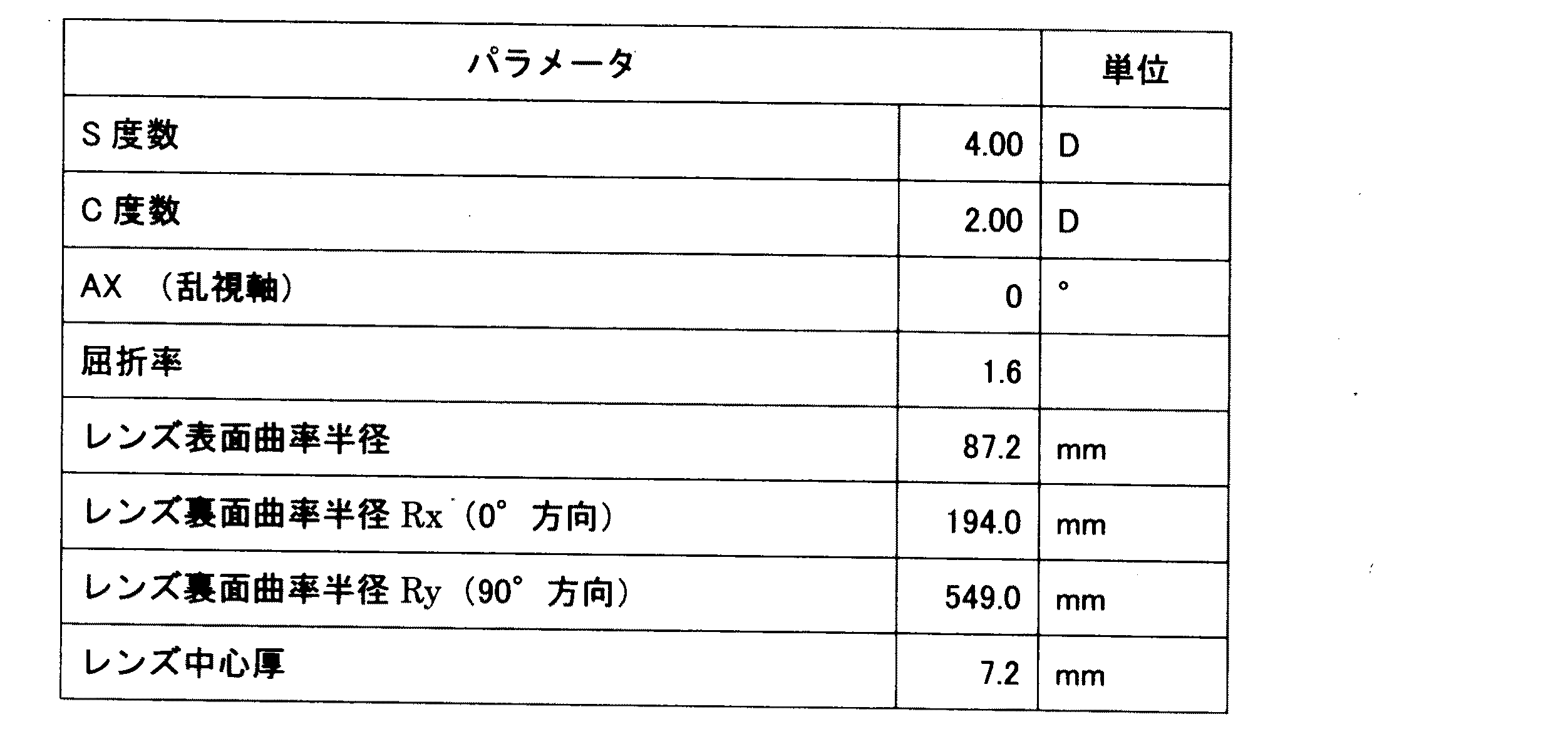
実施例1は単焦点マイナスレンズの例である。実施例1のレンズのパラメータは表1の通りである。
実施例1のレンズ表面は球面形状とされ、レンズ裏面側に表1に示す度数でS度数、C度数、乱視軸方向、レンズ裏面の曲率半径(0°方向と90°方向)等の処方に基づいた形状が形成されている。
実施例1におけるレンズ裏面の形状は数1の式によって定義される。数1の式について説明する。数1の式は数2の式で示されるAと、数3の式で示されるBの2つのサグ量の式を合成した実施例1のレンズのトータルのサグ量を示す式となる。Aの式は乱視度数を有する装用者のために乱視度数のある球面レンズの裏面形状を定義する一般式である。Bの式はAの式と合成されることでレンズ周縁の乱視度数をキャンセルする式である。
各式において、Xはレンズ面の水平方向(0°方向)の座標を示し、Yはレンズ面の垂直方向(90°方向)の座標を示す。 Cxはレンズ水平方向(0°方向)の曲率であり、Cyはレンズ垂直方向(90°方向)曲率である。CxはRxの逆数であり、CyはRyの逆数である。Bの式において係数は表1に示すS度数とC度数の等価球面(平均度数)であるS−5の曲率とした。これが目標とするレンズ周縁の度数となる。
数1の式において付加されている(− 6.282E-7h2 + 2.699E-10h3 − 1.116E-13h4 + 3.133E-17h5)の定数は、球面レンズの収差を改善した非球面レンズとするためにサグに与える量である。この定数においてhの項の係数は表1に示すレンズ表面曲率半径、レンズ裏面曲率半径Rx(0°方向)Ry(90°方向)とした場合のhについて収差が最小となる条件で、例えば最小二乗法を使用して最適化計算で求めている。
また、h=X2+Y2 である。つまり、実施例1は非球面レンズについて周縁側に向かって乱視度数をキャンセルする設計とされている。
gはレンズ中心からの距離に応じてA式とB式を配分するための係数となる変数である。実施例1では、一例としてg=sqrt(0.01875X2 + 0.0375Y2)としている。Aの式は(1−g)が係数となり、Bの式はgが係数となる。gに関してAとBは一次関数の関係であり変化量は直線的であるため乱視度数は急激に減少することはない。そのため、中心寄りほどAの式が支配し、周縁寄り位置ほどBの式の影響が大きくなる。つまりレンズ周縁に向かって徐々に乱視度数が減少して(漸減して)いく。実施例1ではレンズ径と乱視度数のキャンセル度合いに応じて(1−g)がマイナスにならないように係数が設定される。また、Aの式において厚い側(垂直方向(90°方向))のサグが小さくなるようにX2に対してY2の係数を大きく(ここでは一例として2倍に)している。
Hereinafter, examples of simulating the single focus lens of the present invention will be described.
<Example 1>
Example 1 is an example of a single focus minus lens. The parameters of the lens of Example 1 are as shown in Table 1.
The lens surface of Example 1 has a spherical shape, and the dioptric powers shown in Table 1 on the back surface side of the lens are used to formulate S dioptric power, C dioptric power, astigmatic axis direction, radius of curvature of the lens back surface (0 ° direction and 90 ° direction), etc. The shape based on it is formed.
The shape of the back surface of the lens in the first embodiment is defined by the equation of
In each equation, X indicates the coordinates in the horizontal direction (0 ° direction) of the lens surface, and Y indicates the coordinates in the vertical direction (90 ° direction) of the lens surface. Cx is the curvature in the horizontal direction of the lens (0 ° direction), and Cy is the curvature in the vertical direction of the lens (90 ° direction). Cx is the reciprocal of Rx and Cy is the reciprocal of Ry. In the formula B, the coefficient is the curvature of S-5, which is an equivalent spherical surface (average frequency) of S frequency and C frequency shown in Table 1. This is the target power of the lens periphery.
The constant (− 6.282E-7h 2 + 2.699E-10h 3 − 1.116E-13h 4 + 3.133E-17h 5 ) added in the equation of
Further, h = X 2 + Y 2 . That is, the first embodiment is designed to cancel the astigmatic power of the aspherical lens toward the peripheral side.
g is a variable that serves as a coefficient for allocating equations A and B according to the distance from the center of the lens. In Example 1, g = sqrt (0.01875X 2 + 0.0375Y 2 ) is set as an example. In the formula A, (1-g) is a coefficient, and in the formula B, g is a coefficient. Since A and B are linear functions with respect to g and the amount of change is linear, the astigmatic power does not decrease sharply. Therefore, the formula A is dominated toward the center, and the influence of the formula B is greater toward the peripheral position. That is, the astigmatic power gradually decreases (decreases) toward the peripheral edge of the lens. In the first embodiment, the coefficient is set so that (1-g) does not become negative according to the degree of cancellation of the lens diameter and the astigmatic power. Further, in the equation A, the coefficient of Y 2 is increased (here, as an example, doubled) with respect to X 2 so that the sag on the thick side (vertical direction (90 ° direction)) becomes small.
![]()
![]()
![]()
![]()
このような実施例1のレンズの特性をシミュレーションした結果を図3及び図4(a)(b)に基づいて説明する。
図3はレンズの乱視度数のみに着目した度数(パワー)の変化をシミュレーションした乱視度数分布図である。X−Y方向の角度は眼回中心からレンズ裏面中心までのレンズを25mmとした際のレンズ裏面中心方向を原点として視線方向の角度を示している。図3では中心領域はこの実施例1のレンズに設定された−2.00Dとされ、等高線がマイナスである場合にはパワーが減少していることを示す。図3によれば中心領域で水平方向も垂直方向も処方された乱視度数となっているが、周囲に向かって徐々にかつ比較的バランスよく周囲に向かって距離に応じて均等に乱視度数が減少していき、20〜30°付近では−0.75D前後、つまり−1.50〜−1.25Dに乱視度数が軽減されている。
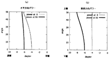
図4(a)(b)は眼回中心からレンズ裏面中心までのレンズを25mmとした際の視線方向の移動にともなうパワーの変化をシミュレーションしたグラフである。まず乱視軸方向である水平方向の変化を示す図4(a)では、太線で示される垂直方向で乱視が矯正されて中央寄り(0°付近)では−6.00Dのパワーである。この−6.00Dのパワーはマイナスレンズの性質上視線がレンズ周縁ほど増大する傾向となるが、本実施例1ではレンズ周縁に向かって徐々に乱視度数を減少させているため、度数が相殺されて−6.00Dのパワーが維持されていることがわかる。一方、細線で示される水平方向では−6.00Dのパワーであるがレンズの性質に基づいてレンズ周縁方向に向かって増大する傾向となる。
一方、乱視軸と直交する方向である垂直方向の変化を示す図4(b)では、太線で示される垂直方向で、乱視度数が減少している。これは図3をよく反映する結果となっている。細線で示される水平方向では−4.00Dのパワーがほぼ維持されている。
The result of simulating the characteristics of the lens of the first embodiment will be described with reference to FIGS. 3 and 4 (a) and 4 (b).
FIG. 3 is an astigmatic dioptric power distribution diagram simulating a change in dioptric power (power) focusing only on the astigmatic dioptric power of the lens. The angle in the XY direction indicates the angle in the line-of-sight direction with the center direction of the back surface of the lens as the origin when the lens from the center of the eye rotation to the center of the back surface of the lens is 25 mm. In FIG. 3, the central region is −2.00D set for the lens of the first embodiment, and when the contour line is negative, the power is reduced. According to FIG. 3, the astigmatic dioptric power is prescribed in both the horizontal and vertical directions in the central region, but the astigmatic dioptric power gradually decreases toward the periphery in a relatively well-balanced manner according to the distance. In the vicinity of 20 to 30 °, the astigmatic power is reduced to around −0.75D, that is, −1.50 to −1.25D.
FIGS. 4 (a) and 4 (b) are graphs simulating the change in power with movement in the line-of-sight direction when the lens from the center of the eye rotation to the center of the back surface of the lens is 25 mm. First, in FIG. 4A showing the change in the horizontal direction, which is the direction of the astigmatism axis, the astigmatism is corrected in the vertical direction indicated by the thick line, and the power is −6.00D near the center (near 0 °). Due to the nature of the minus lens, the line of sight tends to increase toward the peripheral edge of the lens, but in the first embodiment, the astigmatic dioptric power is gradually reduced toward the peripheral edge of the lens, so that the dioptric power is offset. It can be seen that the power of -6.00D is maintained. On the other hand, in the horizontal direction indicated by the thin line, the power is −6.00D, but tends to increase toward the peripheral edge of the lens based on the properties of the lens.
On the other hand, in FIG. 4B showing the change in the vertical direction which is the direction orthogonal to the astigmatic axis, the astigmatic power decreases in the vertical direction indicated by the thick line. This is a result that reflects FIG. 3 well. In the horizontal direction indicated by the thin line, the power of -4.00D is almost maintained.
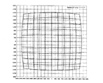
図5は実施例1の単焦点レンズを通した際の方眼の歪曲度合いから歪曲収差を確認するための図であり、レンズ表面から4m離れたところにある正面視線に対して垂直な平面上の格子の見え方をシミュレーションしたものである。格子1つのサイズは、60cm×60cmで全体のサイズは600cm×600cmである。この図において、中心の4つの格子(120cm×120cm)を、レンズを通して目視したときの縦横比(横÷縦)は、1.056である(縦横比が1に近ければ近いほど、空間の歪みの感じ方は小さい)。一方、レンズの周辺部を含んで全体を目視したときの縦横比は、実施例1においては、1.042である。つまり、周辺部における歪みが小さくなっていることになる。これからわかるように中心寄りに対して周縁部分の歪曲が改善されていることがわかる。この改善は乱視度数がキャンセルされたことによる反映である。
このような実施例1の単焦点レンズであれば、装用者が装用した際に中心領域付近で処方に基づいた乱視矯正がなされ、周縁寄りでは全域で処方された乱視度数がキャンセルされるため、眼の疲れや歩く際のふらつき感が軽減されることとなる。
FIG. 5 is a diagram for confirming distortion from the degree of distortion of the grid when passing through the single focus lens of Example 1, and is on a plane perpendicular to the front line of sight at a distance of 4 m from the lens surface. This is a simulation of how the grid looks. The size of one grid is 60 cm x 60 cm and the overall size is 600 cm x 600 cm. In this figure, the aspect ratio (horizontal ÷ vertical) when the four central grids (120 cm × 120 cm) are viewed through a lens is 1.056 (the closer the aspect ratio is to 1, the more the spatial distortion. Feeling is small). On the other hand, the aspect ratio when the entire lens including the peripheral portion is visually observed is 1.042 in the first embodiment. That is, the distortion in the peripheral portion is reduced. As can be seen from this, it can be seen that the distortion of the peripheral portion is improved with respect to the center. This improvement is a reflection of the cancellation of astigmatic power.
With such a single focus lens of Example 1, when the wearer wears it, astigmatism correction based on the prescription is performed in the vicinity of the central region, and the astigmatism dioptric power prescribed in the entire region is canceled near the periphery. The tiredness of the eyes and the feeling of wobbling when walking will be reduced.
<実施例2>
実施例2も単焦点マイナスレンズの例である。実施例2のレンズのパラメータも表1の通りである。
実施例2のレンズ表面も球面形状とされ、レンズ裏面側に表1に示す度数でS度数、C度数、乱視軸方向、レンズ裏面の曲率半径(0°方向と90°方向)等の処方に基づいた形状が形成されている。
実施例2におけるレンズ裏面の形状は数4の式によって定義される。数4の式について説明する。数4の式は数1の式と同様、数2の式で示されるAと、数3の式で示されるBの2つのサグ量の式を合成した実施例2のレンズのトータルのサグ量を示す式となる。Aの式とBの式は実施例1と同じであるため説明は省略する。また、数3の付加されている定数も実施例1の数1と同じであるため説明は省略する。gはレンズ中心からの距離に応じてA式とB式を配分するための係数となる変数であり、式としては実施例1と同じであるが、実施例2では実施例1と異なる係数を採用した。すなわち、g=sqrt(0.0125X2 + 0.025Y2)としている。
<Example 2>
Example 2 is also an example of a single focus minus lens. The parameters of the lens of Example 2 are also shown in Table 1.
The lens surface of Example 2 is also spherical, and the dioptric powers shown in Table 1 on the back surface side of the lens can be used to formulate S dioptric power, C dioptric power, astigmatic axis direction, radius of curvature of the back surface of the lens (0 ° direction and 90 ° direction), etc. The shape based on it is formed.
The shape of the back surface of the lens in Example 2 is defined by the equation of
このような実施例2のレンズの特性をシミュレーションした結果を図6及び図7(a)(b)に基づいて説明する。
図6は実施例1と同様にレンズの乱視度数のみに着目した度数(パワー)の変化をシミュレーションした乱視度数分布図である。図6からわかるように実施例2では実施例1よりも中心領域の処方された乱視度数を残した領域を実施例1よりもより広域にしているが、周縁では乱視度数を−0.75減少させた領域を広くとってより緩やかに漸減する設計としている。
図7(a)(b)も実施例1と同様に視線方向の移動にともなうパワーの変化をシミュレーションしたグラフである。実施例1よりもより緩やかに漸減する設計としたことが図7(b)からわかる。
図8は実施例1と同様にレンズ表面から4m離れたところにある正面視線に対して垂直な平面上の格子の見え方をシミュレーションしたものである。実施例2でも、中心の4つの格子(120cm×120cm)を、レンズを通して目視したときの縦横比(横÷縦)は、1.056である。一方、レンズの周辺部を含んで全体を目視したときの縦横比は、実施例2においては、1.046である。つまり、周辺部における歪みが小さくなっていることになる。実施例2の単焦点レンズでも、装用者が装用した際に中心領域付近で処方に基づいた乱視矯正がなされ、周縁寄りでは全域で処方された乱視度数がキャンセルされるため、眼の疲れや歩く際のふらつき感が軽減されることとなる。
The result of simulating the characteristics of the lens of the second embodiment will be described with reference to FIGS. 6 and 7 (a) and 7 (b).
FIG. 6 is an astigmatic dioptric power distribution diagram simulating a change in dioptric power (power) focusing only on the astigmatic dioptric power of the lens as in the first embodiment. As can be seen from FIG. 6, in Example 2, the region where the prescribed astigmatic power of the central region remains is wider than that of Example 1, but the astigmatic power is reduced by −0.75 at the peripheral edge. It is designed to take a wide area and gradually decrease it more slowly.
7 (a) and 7 (b) are also graphs simulating changes in power with movement in the line-of-sight direction, as in Example 1. It can be seen from FIG. 7 (b) that the design was made so as to gradually decrease more slowly than in Example 1.
FIG. 8 is a simulation of the appearance of a grid on a plane perpendicular to the front line of sight at a distance of 4 m from the lens surface, as in the first embodiment. Also in the second embodiment, the aspect ratio (horizontal ÷ vertical) when the four central grids (120 cm × 120 cm) are visually observed through the lens is 1.056. On the other hand, the aspect ratio when the entire lens including the peripheral portion is visually observed is 1.046 in the second embodiment. That is, the distortion in the peripheral portion is reduced. Even with the single focus lens of Example 2, when the wearer wears it, the astigmatism correction based on the prescription is performed near the central region, and the astigmatism power prescribed in the entire region is canceled near the periphery, so that the eyes are tired and walk. The feeling of wobbling will be reduced.
<実施例3>
実施例3も単焦点マイナスレンズの例である。実施例3のレンズのパラメータも表1の通りである。
実施例3のレンズ表面も球面形状とされ、レンズ裏面側に表1に示す度数でS度数、C度数、乱視軸方向、レンズ裏面の曲率半径(0°方向と90°方向)等の処方に基づいた形状が形成されている。
実施例3におけるレンズ裏面の形状は数5の式によって定義される。数5の式について説明する。数5の式は数2の式で示されるAと、数3の式で示されるBの2つのサグ量の式を合成した実施例3のレンズのトータルのサグ量を示す式となる。Aの式とBの式は実施例1と同じであるため説明は省略する。また、数3の付加されている定数も実施例1の数1と同じであるため説明は省略する。gはレンズ中心からの距離に応じてA式とB式を配分するための係数となる変数であり、式としては実施例1と同じであるが、実施例3では実施例1とも実施例2異なる係数を採用した。すなわち、g=sqrt(0.0214X2 + 0.0357Y2)としている。また、実施例3ではAとBへのgの値を配分する式形式をgの二次式とした。
<Example 3>
Example 3 is also an example of a single focus minus lens. The parameters of the lens of Example 3 are also shown in Table 1.
The lens surface of Example 3 is also spherical, and the dioptric powers shown in Table 1 on the back surface side of the lens can be used to formulate S dioptric power, C dioptric power, astigmatic axis direction, radius of curvature of the back surface of the lens (0 ° direction and 90 ° direction), etc. The shape based on it is formed.
The shape of the back surface of the lens in Example 3 is defined by the equation of Equation 5. The equation of Equation 5 will be described. The equation of Equation 5 is an equation showing the total sag amount of the lens of Example 3 obtained by synthesizing the equations of the two sag amounts of A represented by the equation of
このような実施例3のレンズの特性をシミュレーションした結果を図9及び図10(a)(b)に基づいて説明する。
図9は実施例1と同様にレンズの乱視度数のみに着目した度数(パワー)の変化をシミュレーションした乱視度数分布図である。図9によれば実施例3では実施例2よりも中心領域の乱視度数を残した領域を更に広域にするとともに、漸減させるためのAの式とBの式に与えるgの式の配分を二次式としているため、周縁で急激に減少量が増えるという設計である。
図10(a)(b)も実施例1と同様に視線方向の移動にともなうパワーの変化をシミュレーションしたグラフである。特に垂直方向パワーでは周縁で乱視度数が急激に減少することがわかる。
図11は実施例1と同様にレンズ表面から4m離れたところにある正面視線に対して垂直な平面上の格子の見え方をシミュレーションしたものである。実施例3でも、中心の4つの格子(120cm×120cm)を、レンズを通して目視したときの縦横比(横÷縦)は、1.056である。一方、レンズの周辺部を含んで全体を目視したときの縦横比は、実施例2においては、1.054である。つまり、周辺部における歪みが小さくなっていることになる。実施例3の単焦点レンズでも、装用者が装用した際に中心領域付近で処方に基づいた乱視矯正がなされ、周縁寄りでは全域で処方された乱視度数がキャンセルされるため、眼の疲れや歩く際のふらつき感が軽減されることとなる。
The result of simulating the characteristics of the lens of Example 3 will be described with reference to FIGS. 9 and 10 (a) and 10 (b).
FIG. 9 is an astigmatic dioptric power distribution diagram simulating a change in dioptric power (power) focusing only on the astigmatic dioptric power of the lens as in the first embodiment. According to FIG. 9, in the third embodiment, the region where the astigmatic dioptric power of the central region is left is made wider than that of the second embodiment, and the distribution of the equation of g given to the equation of A and the equation of g for gradual reduction is two. Since the following equation is used, the design is such that the amount of decrease increases sharply at the periphery.
10 (a) and 10 (b) are also graphs simulating changes in power with movement in the line-of-sight direction, as in Example 1. In particular, it can be seen that the astigmatic power decreases sharply at the periphery with vertical power.
FIG. 11 is a simulation of the appearance of a grid on a plane perpendicular to the front line of sight at a distance of 4 m from the lens surface, as in the first embodiment. Also in Example 3, the aspect ratio (horizontal ÷ vertical) when the four central grids (120 cm × 120 cm) are visually observed through the lens is 1.056. On the other hand, the aspect ratio when the entire lens including the peripheral portion is visually observed is 1.054 in the second embodiment. That is, the distortion in the peripheral portion is reduced. Even with the single focus lens of Example 3, when the wearer wears it, astigmatism correction based on the prescription is performed near the central region, and the astigmatism dioptric power prescribed in the entire region is canceled near the periphery, resulting in eye fatigue and walking. The feeling of wobbling will be reduced.
<比較例1>
実施例1〜3の比較として、表1と同じ条件でシミュレーションした比較例1の単焦点マイナスレンズを挙げる。比較例1の単焦点レンズは乱視矯正された球面レンズである。比較例1の単焦点レンズではレンズ裏面の形状は数1の式のAの式のみによって定義されている。
比較例1の単焦点レンズのシミュレーションしたレンズ特性を図12及び図13(a)(b)に基づいて説明する。
図12は実施例1〜3と同様にレンズの乱視度数のみに着目した度数(パワー)の変化をシミュレーションした比較例1のレンズの乱視度数分布図である。実施例1〜3と比べて中央領域の−2.00Dの均等な乱視度数のパワーが広く得られる。レンズの左右方向では20°付近から徐々に乱視度数のパワーが減少する傾向となっているものの、レンズの上下方向では乱視度数のパワーが20°以下の段階ですでに増加するような特性となっており、特に上下方向を目視すると処方以上の乱視度数となってしまっていて好ましくない。
図13(a)(b)では水平方向も垂直方向もいずれも太線で示される垂直方向で、乱視度数が増加している。水平方向はマイナスレンズの性質上視線がレンズ周縁ほど増大することからわずかな増加に留まるものの垂直方向では乱視度数は大きく増加している。そのため、眼の疲れや歩く際のふらつきを感じる設計である。
図14は実施例1と同様にレンズ表面から4m離れたところにある正面視線に対して垂直な平面上の格子の見え方をシミュレーションしたものである。比較例1でも、中心の4つの格子(120cm×120cm)を、レンズを通して目視したときの縦横比(横÷縦)は、1.056である。一方、レンズの周辺部を含んで全体を目視したときの縦横比は、比較例1においては、1.066となり悪化している。つまり、比較例1のレンズでは中央寄りは例えば実施例1や実施例2よりも中心付近では歪曲度は同じであるが、全体としては実施例1〜3に比べて湾曲度合いは大きいといえる。
<Comparative example 1>
As a comparison of Examples 1 to 3, a single focus minus lens of Comparative Example 1 simulated under the same conditions as in Table 1 will be mentioned. The single focus lens of Comparative Example 1 is an aspherical lens corrected for astigmatism. In the single focus lens of Comparative Example 1, the shape of the back surface of the lens is defined only by the equation A of the equation of
The simulated lens characteristics of the single focus lens of Comparative Example 1 will be described with reference to FIGS. 12 and 13 (a) and 13 (b).
FIG. 12 is an astigmatic dioptric power distribution diagram of the lens of Comparative Example 1 in which the change in dioptric power (power) focusing only on the astigmatic dioptric power of the lens was simulated in the same manner as in Examples 1 to 3. Compared with Examples 1 to 3, a power with a uniform astigmatic power of −2.00 D in the central region can be obtained widely. In the horizontal direction of the lens, the power of astigmatic power tends to gradually decrease from around 20 °, but in the vertical direction of the lens, the power of astigmatic power has already increased at the stage of 20 ° or less. In particular, when visually observing in the vertical direction, the astigmatic power is higher than the prescribed value, which is not preferable.
In FIGS. 13A and 13B, the astigmatic power is increasing in both the horizontal direction and the vertical direction in the vertical direction indicated by the thick line. Due to the nature of the minus lens in the horizontal direction, the line of sight increases toward the periphery of the lens, so the increase is only slight, but the astigmatic power increases significantly in the vertical direction. Therefore, it is designed so that you can feel tired eyes and wobbling when walking.
FIG. 14 is a simulation of the appearance of a grid on a plane perpendicular to the front line of sight at a distance of 4 m from the lens surface, as in the first embodiment. Also in Comparative Example 1, the aspect ratio (horizontal ÷ vertical) when the four central grids (120 cm × 120 cm) are visually observed through the lens is 1.056. On the other hand, the aspect ratio when the entire lens including the peripheral portion is visually observed is 1.066 in Comparative Example 1, which is deteriorated. That is, in the lens of Comparative Example 1, the degree of distortion is the same in the vicinity of the center as compared with, for example, Examples 1 and 2, but the degree of curvature is larger than that of Examples 1 to 3 as a whole.
<比較例2>
実施例2の比較として、表1と同じ条件でシミュレーションした比較例2の単焦点マイナスレンズを挙げる。比較例2の単焦点レンズは乱視矯正された非球面レンズである。比較例2の単焦点レンズではレンズ裏面の形状は数1の式のAに数1の式の(− 6.282E-7h2 + 2.699E-10h3 − 1.116E-13h4 + 3.133E-17h5)の定数を付加して定義されている。
比較例2の単焦点レンズのシミュレーションしたレンズ特性を図15及び図16(a)(b)に基づいて説明する。
図15は実施例1〜3と同様にレンズの乱視度数のみに着目した度数(パワー)の変化をシミュレーションした比較例2のレンズの乱視度数分布図である。実施例1〜3と比べて中央領域の−2.00Dの均等な乱視度数のパワーが横方向に大きく拡がっており、比較例1と比較した場合に水平方向の収差は大きく改善されているが、上下方向では実施例1〜3と異なり乱視度数は増大している。
図16(a)に示すように、比較例2では水平方向パワーは良好であるが、図16(b)のように太線で示される垂直方向では乱視度数は増大している。そのため、上下方向においては眼の疲れや歩く際のふらつきを感じる設計である。
図17は実施例1と同様にレンズ表面から4m離れたところにある正面視線に対して垂直な平面上の格子の見え方をシミュレーションしたものである。比較例2でも、中心の4つの格子(120cm×120cm)を、レンズを通して目視したときの縦横比(横÷縦)は、1.056である。一方、レンズの周辺部を含んで全体を目視したときの縦横比は、比較例2においては、1.064となり悪化している。つまり、比較例1のレンズでは中央寄りは例えば実施例1や実施例2よりも中心付近では歪曲度は同じであるが、全体としては実施例1〜3に比べて湾曲度合いは大きいといえる。
<Comparative example 2>
As a comparison of Example 2, a single focus minus lens of Comparative Example 2 simulated under the same conditions as in Table 1 will be mentioned. The single focus lens of Comparative Example 2 is an aspherical lens corrected for astigmatism. In the single focus lens of Comparative Example 2, the shape of the back surface of the lens is A of
The simulated lens characteristics of the single focus lens of Comparative Example 2 will be described with reference to FIGS. 15 and 16 (a) and 16 (b).
FIG. 15 is an astigmatic dioptric power distribution diagram of the lens of Comparative Example 2 in which the change in dioptric power (power) focusing only on the astigmatic dioptric power of the lens was simulated in the same manner as in Examples 1 to 3. Compared with Examples 1 to 3, the power of the uniform astigmatic power of −2.00 D in the central region is greatly expanded in the lateral direction, and the aberration in the horizontal direction is greatly improved as compared with Comparative Example 1. In the vertical direction, the astigmatic power is increased unlike Examples 1 to 3.
As shown in FIG. 16A, the horizontal power is good in Comparative Example 2, but the astigmatic power is increased in the vertical direction shown by the thick line as shown in FIG. 16B. Therefore, it is designed so that you can feel tired eyes and wobbling when walking in the vertical direction.
FIG. 17 is a simulation of the appearance of a grid on a plane perpendicular to the front line of sight at a distance of 4 m from the lens surface, as in the first embodiment. Also in Comparative Example 2, the aspect ratio (horizontal ÷ vertical) when the four central grids (120 cm × 120 cm) are visually observed through the lens is 1.056. On the other hand, the aspect ratio when the entire lens including the peripheral portion is visually observed is 1.064 in Comparative Example 2, which is deteriorated. That is, in the lens of Comparative Example 1, the degree of distortion is the same in the vicinity of the center as compared with, for example, Examples 1 and 2, but the degree of curvature is larger than that of Examples 1 to 3 as a whole.
<実施例4>
実施例4は単焦点プラスレンズである。実施例4のレンズのパラメータは表2の通りである。
実施例4のレンズ表面は球面形状とされ、レンズ裏面側に表2に示す度数でS度数、C度数、乱視軸方向、レンズ裏面の曲率半径(0°方向と90°方向)等の処方に基づいた形状が形成されている。
実施例4におけるレンズ裏面の形状は数6の式によって定義される。数6の式について説明する。数6の式は、数2の式で示されるAと、数7の式で示されるBの2つのサグ量の式を合成した実施例4のレンズのトータルのサグ量を示す式となる。Aの式は実施例1と同じであるため説明は省略する。Bの式はAの式と合成されることでレンズ周縁の乱視度数をキャンセルする式である。
数6の式において付加されている(+ 1.437E-6h2 − 1.370E-9h3 + 9.998E-13h4 − 3.511E-16h5)の定数は、球面レンズの収差を改善した非球面レンズとするためにサグに与える量である。この定数においてhの項の係数は表2に示すレンズ表面曲率半径、レンズ裏面曲率半径Rx(0°方向)Ry(90°方向)とした場合のhについて収差が最小となる条件で、例えば最小二乗法を使用して最適化計算で求めている。尚、実施例4ではh=Y2 とおいた。実施例1〜3のような回転対称非球面としてhを設定すると本発明に好適な数値が得られにくいため、Y方向のみの条件で修正を与えるようにした。
<Example 4>
Example 4 is a single focus plus lens. The parameters of the lens of Example 4 are as shown in Table 2.
The lens surface of Example 4 has a spherical shape, and the dioptric powers shown in Table 2 on the back surface side of the lens are used to formulate S dioptric power, C dioptric power, astigmatic axis direction, radius of curvature of the lens back surface (0 ° direction and 90 ° direction), and the like. The shape based on it is formed.
The shape of the back surface of the lens in Example 4 is defined by the equation of
The constants (+ 1.437E-6h 2 − 1.370E-9h 3 + 9.998E-13h 4 − 3.511E-16h 5 ) added in the equation of Eq. 6 are the aspherical lens with improved aberration of the spherical lens. The amount given to the sag to do. In this constant, the coefficient of the term h is, for example, the minimum under the condition that the aberration is the minimum with respect to h when the lens surface curvature radius and the lens back surface curvature radius Rx (0 ° direction) Ry (90 ° direction) are shown in Table 2. It is calculated by optimization using the square method. In Example 4, h = Y 2 was set. When h is set as the rotationally symmetric aspherical surface as in Examples 1 to 3, it is difficult to obtain a numerical value suitable for the present invention. Therefore, the correction is given only in the Y direction.
このような実施例4のレンズの特性をシミュレーションした結果を図18及び図19(a)(b)に基づいて説明する。
図18は実施例1と同様にレンズの乱視度数のみに着目した度数(パワー)の変化をシミュレーションした乱視度数分布図である。図18からわかるように実施例4では半径10〜15mm程度の中心領域に処方の+2.00Dの乱視矯正度数が設けられその周囲に周縁に向かって徐々ににかつ比較的バランスよく周囲に向かって距離に応じて均等に乱視度数が減少していき、30°付近では−0.75D前後、つまり+0.25D程度まで乱視度数が軽減されている。また、更に30°より外側も徐々に乱視度数は軽減されている。
図19(a)(b)では特に、乱視軸と直交する方向である垂直方向の変化を示す図19(b)では、太線で示される垂直方向で、乱視度数が減少している。これは図18をよく反映する結果となっている。
図20は実施例4の単焦点レンズを通した際の方眼の歪曲度合いから歪曲収差を確認するための図であり、レンズ表面から4m離れたところにある正面視線に対して垂直な平面上の格子の見え方をシミュレーションしたものである。格子1つのサイズは、30cm×30cmで全体のサイズは300cm×300cmである。この図において、中心の4つの格子(60cm×60cm)を、レンズを通して目視したときの縦横比(横÷縦)は、0.940である。一方、レンズの周辺部を含んで全体を目視したときの縦横比は、実施例4においては、0.949である(縦横比が1に近ければ近いほど、空間の歪みの感じ方は小さい)。つまり、周辺部において歪みが小さくなっていることになる。これからわかるように中心寄りに対して周縁部分の歪曲が改善されていることがわかる。この改善は乱視度数がキャンセルされたことによる反映である。
このような実施例4の単焦点レンズであれば、装用者が装用した際に中心領域付近で処方に基づいた乱視矯正がなされ、周縁寄りでは全域で処方された乱視度数がキャンセルされるため、眼の疲れや歩く際のふらつき感が軽減されることとなる。
The results of simulating the characteristics of the lens of Example 4 will be described with reference to FIGS. 18 and 19 (a) and 19 (b).
FIG. 18 is an astigmatic dioptric power distribution diagram simulating a change in dioptric power (power) focusing only on the astigmatic dioptric power of the lens as in the first embodiment. As can be seen from FIG. 18, in the fourth embodiment, the prescribed + 2.00D astigmatism correction power is provided in the central region having a radius of about 10 to 15 mm, and the astigmatism correction power is gradually and relatively well-balanced toward the periphery. The astigmatic dioptric power decreases evenly according to the distance, and the astigmatic dioptric power is reduced to around −0.75D, that is, about +0.25D at around 30 °. Further, the astigmatic power is gradually reduced outside the 30 °.
In particular, in FIGS. 19 (a) and 19 (b), the astigmatic dioptric power decreases in the vertical direction indicated by the thick line, which shows the change in the vertical direction which is the direction orthogonal to the astigmatic axis. This is a result that reflects FIG. 18 well.
FIG. 20 is a diagram for confirming distortion from the degree of distortion of the grid when passing through the single focus lens of Example 4, and is on a plane perpendicular to the front line of sight at a distance of 4 m from the lens surface. This is a simulation of how the grid looks. The size of one grid is 30 cm x 30 cm and the overall size is 300 cm x 300 cm. In this figure, the aspect ratio (horizontal ÷ vertical) when the four central grids (60 cm × 60 cm) are visually observed through a lens is 0.940. On the other hand, the aspect ratio when the entire lens including the peripheral portion is visually observed is 0.949 in the fourth embodiment (the closer the aspect ratio is to 1, the smaller the feeling of distortion in the space is). .. That is, the distortion is small in the peripheral portion. As can be seen from this, it can be seen that the distortion of the peripheral portion is improved with respect to the center. This improvement is a reflection of the cancellation of astigmatic power.
With such a single focus lens of Example 4, when the wearer wears it, astigmatism correction based on the prescription is performed in the vicinity of the central region, and the astigmatism dioptric power prescribed in the entire region is canceled near the periphery. The tiredness of the eyes and the feeling of wobbling when walking will be reduced.
<比較例3>
実施例4の比較として、表2と同じ条件でシミュレーションした比較例3の単焦点プラスレンズを挙げる。比較例3の単焦点レンズは乱視矯正された球面レンズである。比較例3の単焦点レンズではレンズ裏面の形状は数1の式のAの式のみによって定義されている。
比較例3の単焦点レンズのシミュレーションしたレンズ特性を図21及び図22(a)(b)に基づいて説明する。
図21は実施例4と同様にレンズの乱視度数のみに着目した度数(パワー)の変化をシミュレーションした比較例3のレンズの乱視度数分布図である。実施例4と比べて中央領域の+2.00Dの均等な乱視度数のパワーが広く得られる。レンズの左右方向では20°付近から徐々に乱視度数のパワーが減少する傾向となっているものの、レンズの上下方向では乱視度数のパワーが20°以下の段階ですでに増加するような特性となっており、特に上下方向を目視すると処方以上の乱視度数となってしまっていて好ましくない。
図22(a)(b)では特に垂直方向パワーにおいて太線で示される垂直方向で、乱視度数が増加している。そのため、眼の疲れや歩く際のふらつきを感じる設計である。
図23は実施例4と同様にレンズ表面から4m離れたところにある正面視線に対して垂直な平面上の格子の見え方をシミュレーションしたものである。比較例3でも、中心の4つの格子(60cm×60cm)を、レンズを通して目視したときの縦横比(横÷縦)は、0.940である。一方、レンズの周辺部を含んで全体を目視したときの縦横比は、比較例2においては、0.923となり悪化している。つまり、比較例1のレンズでは中央寄りは例えば実施例1や実施例2よりも中心付近では歪曲度は同じであるが、全体としては実施例4に比べて湾曲度合いは大きいといえる。
<Comparative example 3>
As a comparison of Example 4, a single focus plus lens of Comparative Example 3 simulated under the same conditions as in Table 2 will be mentioned. The single focus lens of Comparative Example 3 is an aspherical lens corrected for astigmatism. In the single focus lens of Comparative Example 3, the shape of the back surface of the lens is defined only by the formula A of the
The simulated lens characteristics of the single focus lens of Comparative Example 3 will be described with reference to FIGS. 21 and 22 (a) and 22 (b).
FIG. 21 is a distribution diagram of the astigmatic dioptric power of the lens of Comparative Example 3 in which the change in the dioptric power (power) focusing only on the astigmatic dioptric power of the lens is simulated as in the fourth embodiment. Compared with Example 4, the power of the uniform astigmatic power of + 2.00D in the central region can be widely obtained. In the horizontal direction of the lens, the power of astigmatic power tends to gradually decrease from around 20 °, but in the vertical direction of the lens, the power of astigmatic power has already increased at the stage of 20 ° or less. In particular, when visually observing in the vertical direction, the astigmatic power is higher than the prescribed value, which is not preferable.
In FIGS. 22 (a) and 22 (b), the astigmatic power increases in the vertical direction shown by the thick line, especially in the vertical power. Therefore, it is designed so that you can feel tired eyes and wobbling when walking.
FIG. 23 is a simulation of the appearance of a grid on a plane perpendicular to the front line of sight at a distance of 4 m from the lens surface, as in the fourth embodiment. Also in Comparative Example 3, the aspect ratio (horizontal ÷ vertical) when the four central grids (60 cm × 60 cm) are visually observed through the lens is 0.940. On the other hand, the aspect ratio when the entire lens including the peripheral portion is visually observed is 0.923 in Comparative Example 2, which is deteriorated. That is, in the lens of Comparative Example 1, the degree of distortion is the same in the vicinity of the center as compared with, for example, Example 1 and Example 2, but the degree of curvature is larger than that of Example 4 as a whole.
<比較例4>
実施例2の比較として、表2と同じ条件でシミュレーションした比較例4の単焦点マイナスレンズを挙げる。比較例4の単焦点レンズは乱視矯正された非球面レンズである。比較例4の単焦点レンズではレンズ裏面の形状は数1の式のAに(4.224E-7h2 - 3.612E-10h3 + 2.1114E-13h4 - 5.828E-17h5)の定数を付加して定義されている。h=X2+Y2である。
比較例4の単焦点レンズのシミュレーションしたレンズ特性を図24及び図25(a)(b)に基づいて説明する。
図24は実施例4と同様にレンズの乱視度数のみに着目した度数(パワー)の変化をシミュレーションした比較例2のレンズの乱視度数分布図である。実施例4や比較例3と比べて中央領域の+2.00Dの均等な乱視度数のパワーは横方向に大きく拡がっており、比較例2と比較した場合に水平方向の収差は大きく改善されているが、上下方向では実施例4と異なり乱視度数は増大している。
図25(a)では比較例3ほどではないものの特に垂直方向パワーにおいて太線で示される垂直方向で、乱視度数が増加している。そのため、上下方向においては眼の疲れや歩く際のふらつきを感じる設計である。
図26は実施例4と同様にレンズ表面から4m離れたところにある正面視線に対して垂直な平面上の格子の見え方をシミュレーションしたものである。比較例4でも、中心の4つの格子(60cm×60cm)を、レンズを通して目視したときの縦横比(横÷縦)は、0.940である。一方、レンズの周辺部を含んで全体を目視したときの縦横比は、比較例2においては、0.921となり悪化している。つまり、比較例1のレンズでは中央寄りは例えば実施例1や実施例2よりも中心付近では歪曲度は同じであるが、全体としては実施例4に比べて湾曲度合いは大きいといえる。
<Comparative example 4>
As a comparison of Example 2, a single focus minus lens of Comparative Example 4 simulated under the same conditions as in Table 2 will be mentioned. The single focus lens of Comparative Example 4 is an aspherical lens corrected for astigmatism. In the single focus lens of Comparative Example 4, the shape of the back surface of the lens is A with
The simulated lens characteristics of the single focus lens of Comparative Example 4 will be described with reference to FIGS. 24 and 25 (a) and 25 (b).
FIG. 24 is a distribution diagram of the astigmatic dioptric power of the lens of Comparative Example 2 in which the change of the dioptric power (power) focusing only on the astigmatic dioptric power of the lens is simulated as in the fourth embodiment. Compared with Example 4 and Comparative Example 3, the power of the uniform astigmatic power of + 2.00D in the central region is greatly expanded in the lateral direction, and the aberration in the horizontal direction is greatly improved as compared with Comparative Example 2. However, in the vertical direction, the astigmatic power is increased unlike the fourth embodiment.
In FIG. 25 (a), the astigmatic power is increased in the vertical direction indicated by the thick line, particularly in the vertical power, although not as much as in Comparative Example 3. Therefore, it is designed so that you can feel tired eyes and wobbling when walking in the vertical direction.
FIG. 26 is a simulation of the appearance of a grid on a plane perpendicular to the front line of sight at a distance of 4 m from the lens surface, as in the fourth embodiment. Also in Comparative Example 4, the aspect ratio (horizontal ÷ vertical) when the four central grids (60 cm × 60 cm) are visually observed through the lens is 0.940. On the other hand, the aspect ratio when the entire lens including the peripheral portion is visually observed is 0.921 in Comparative Example 2, which is deteriorated. That is, in the lens of Comparative Example 1, the degree of distortion is the same in the vicinity of the center as compared with, for example, Example 1 and Example 2, but the degree of curvature is larger than that of Example 4 as a whole.
上記実施の形態は本発明の原理およびその概念を例示するための具体的な実施の形態として記載したにすぎない。つまり、本発明は上記の実施の形態に限定されるものではない。本発明は、例えば次のように変更した態様で具体化することも可能である。
・上記各実施例において、例えばS度数やC度数や乱視軸方向等の諸条件は任意に変更可能である。
・上記実施例では非球面レンズに対して周縁に向かって乱視度数を軽減する修正を加えるような設計であったが、球面レンズをベースとして周縁の乱視度数を軽減するようにしてもよい。
・上記の非球面設計のために算出された具体的な係数(数値)は一例である。他の計算手法や処方条件によって当然変更される係数である。
・gの式における係数(数値)はシミュレーション結果に応じて適宜変更して好適な係数を与えるようにしてもよい。
本願発明は上述した実施の形態に記載の構成に限定されない。上述した各実施の形態や変形例の構成要素は任意に選択して組み合わせて構成するとよい。また各実施の形態や変形例の任意の構成要素と、発明を解決するための手段に記載の任意の構成要素または発明を解決するための手段に記載の任意の構成要素を具体化した構成要素とは任意に組み合わせて構成するとよい。これらについても本願の補正または分割出願等において権利取得する意思を有する。
また、意匠出願への変更出願により、全体意匠または部分意匠について権利取得する意思を有する。図面は本装置の全体を実線で描画しているが、全体意匠のみならず当該装置の一部の部分に対して請求する部分意匠も包含した図面である。例えば当該装置の一部の部材を部分意匠とすることはもちろんのこと、部材と関係なく当該装置の一部の部分を部分意匠として包含した図面である。当該装置の一部の部分としては、装置の一部の部材としてもよいし、その部材の部分としてもよい。
The above-described embodiment is merely described as a specific embodiment for exemplifying the principle of the present invention and the concept thereof. That is, the present invention is not limited to the above-described embodiment. The present invention can also be embodied in a modified manner as follows, for example.
-In each of the above embodiments, various conditions such as S power, C power, and astigmatic axis direction can be arbitrarily changed.
-In the above embodiment, the aspherical lens is designed to reduce the astigmatic dioptric power toward the peripheral edge, but the astigmatic dioptric power of the peripheral edge may be reduced based on the spherical lens.
-The specific coefficients (numerical values) calculated for the above aspherical design are examples. It is a coefficient that is naturally changed by other calculation methods and prescription conditions.
-The coefficient (numerical value) in the formula of g may be appropriately changed according to the simulation result to give a suitable coefficient.
The present invention is not limited to the configuration described in the above-described embodiment. The components of each of the above-described embodiments and modifications may be arbitrarily selected and combined. Further, any component of each embodiment or modification, and any component described in the means for solving the invention or a component described in the means for solving the invention are embodied. And may be configured in any combination. We also intend to acquire the rights to these in the amendment or divisional application of the present application.
In addition, he / she intends to acquire the right to the whole design or the partial design by filing a change application to a design application. Although the entire drawing of the device is drawn with solid lines, it is a drawing that includes not only the whole design but also the partial design requested for a part of the device. For example, it is a drawing which includes a part of the device as a partial design regardless of the member as well as a part of the member of the device as a partial design. As a part of the device, it may be a part of the device or a part of the member.
1…単焦点レンズであるマイナスレンズ、2…単焦点レンズであるプラスレンズ。 1 ... A minus lens that is a single focus lens, 2 ... A plus lens that is a single focus lens.
Claims (10)
レンズ中心を含むレンズ中央領域で所定の乱視矯正度数が設定され、前記レンズ中央領域からレンズ周辺に向かって前記所定の乱視矯正度数が漸減されていることを特徴とする単焦点レンズ。 In a single focus lens with astigmatism correction power for astigmatism correction
A single focus lens characterized in that a predetermined astigmatism correction dioptric power is set in a lens central region including the lens center, and the predetermined astigmatism correction dioptric power is gradually decreased from the lens central region toward the periphery of the lens.
基準となる球面又は非球面に構成されたベース面に対して、レンズ体の中心を含んでレンズ面に垂直に交わる平面と同レンズ面との交わりによってできる断面曲線の曲率が最大となる方向と最小となる方向が直交又は略直交するような乱視矯正面の曲面と、
レンズ中心を含むレンズ中央領域から周縁に向かって前記断面曲線の曲率が均等となる修正面の曲面とを合成するようにしたことを特徴とする単焦点レンズの設計方法。 A method for designing a single focus lens in which a predetermined astigmatism correction power is set in a lens center region including the lens center, and the predetermined astigmatism correction power is gradually reduced from the lens center region toward the periphery of the lens.
The direction in which the curvature of the cross-sectional curve formed by the intersection of the plane intersecting the lens surface perpendicularly to the lens surface including the center of the lens body with respect to the base surface formed on the reference spherical surface or aspherical surface is maximized. A curved surface of the aspherical vision correction surface whose minimum direction is orthogonal or substantially orthogonal,
A method for designing a single focus lens, characterized in that a curved surface of a correction surface having a uniform curvature of the cross-sectional curve is combined from a central region of the lens including the center of the lens toward the peripheral edge.
Priority Applications (1)
| Application Number | Priority Date | Filing Date | Title |
|---|---|---|---|
| JP2019220947A JP7511864B2 (en) | 2019-12-06 | 2019-12-06 | Single focus lens and its design method |
Applications Claiming Priority (1)
| Application Number | Priority Date | Filing Date | Title |
|---|---|---|---|
| JP2019220947A JP7511864B2 (en) | 2019-12-06 | 2019-12-06 | Single focus lens and its design method |
Publications (2)
| Publication Number | Publication Date |
|---|---|
| JP2021089399A true JP2021089399A (en) | 2021-06-10 |
| JP7511864B2 JP7511864B2 (en) | 2024-07-08 |
Family
ID=76220249
Family Applications (1)
| Application Number | Title | Priority Date | Filing Date |
|---|---|---|---|
| JP2019220947A Active JP7511864B2 (en) | 2019-12-06 | 2019-12-06 | Single focus lens and its design method |
Country Status (1)
| Country | Link |
|---|---|
| JP (1) | JP7511864B2 (en) |
Citations (2)
| Publication number | Priority date | Publication date | Assignee | Title |
|---|---|---|---|---|
| JP2000105357A (en) * | 1998-09-29 | 2000-04-11 | Seiko Epson Corp | Both-surface aspherical lens for spectacles |
| JP2006505007A (en) * | 2002-10-31 | 2006-02-09 | ジョンソン・アンド・ジョンソン・ビジョン・ケア・インコーポレイテッド | Progressive cylindrical power ophthalmic lens |
-
2019
- 2019-12-06 JP JP2019220947A patent/JP7511864B2/en active Active
Patent Citations (2)
| Publication number | Priority date | Publication date | Assignee | Title |
|---|---|---|---|---|
| JP2000105357A (en) * | 1998-09-29 | 2000-04-11 | Seiko Epson Corp | Both-surface aspherical lens for spectacles |
| JP2006505007A (en) * | 2002-10-31 | 2006-02-09 | ジョンソン・アンド・ジョンソン・ビジョン・ケア・インコーポレイテッド | Progressive cylindrical power ophthalmic lens |
Also Published As
| Publication number | Publication date |
|---|---|
| JP7511864B2 (en) | 2024-07-08 |
Similar Documents
| Publication | Publication Date | Title |
|---|---|---|
| JP3852116B2 (en) | Progressive multifocal lens and spectacle lens | |
| JP3800629B2 (en) | Multifocal lens for spectacles and spectacle lens | |
| JP4979774B2 (en) | Pair of progressive-power lenses and design method thereof | |
| JP5496798B2 (en) | Progressive eyeglass lens having two aspheric surfaces, in particular a progressive surface, and method for calculating the eyeglass lens | |
| KR102042554B1 (en) | A method for determining an ophthalmic lens | |
| JP7054938B2 (en) | Low-convergence glasses | |
| JP5952541B2 (en) | Optical lens, optical lens design method, and optical lens manufacturing apparatus | |
| JP2019530904A (en) | Eye strain reduction lens | |
| JP5897260B2 (en) | Progressive power lens and design method thereof | |
| WO2013151165A1 (en) | Progressive-power lens and method for designing progressive-power lens | |
| JP5822483B2 (en) | Eyeglass lenses | |
| JP2019530905A (en) | Lens with off-axis curvature center | |
| JP5822484B2 (en) | Eyeglass lenses | |
| JP2016026324A (en) | Lens for spectacle, spectacle, design method of spectacle lens, and design device | |
| US12007627B2 (en) | Method, manufacturing method, and design system of progressive addition lens, and progressive addition lens | |
| JP5822482B2 (en) | Eyeglass lenses | |
| JP2021089399A (en) | Fixed focal lens and design method therefor | |
| EP4078269A1 (en) | Method for determining an optical lens | |
| JP6095271B2 (en) | Lens set, lens design method, and lens manufacturing method | |
| JP3236263B2 (en) | Aspherical spectacle lens design method | |
| JP2010513985A (en) | Improved single vision glasses | |
| JP2010237402A (en) | Progressive refractive power spectacle lens and method of manufacturing the same | |
| JP2010513985A5 (en) | ||
| JP2004126256A (en) | Double-side aspherical progressive power lens | |
| JP2002040373A (en) | Aspheric spectacle lens |
Legal Events
| Date | Code | Title | Description |
|---|---|---|---|
| A621 | Written request for application examination |
Free format text: JAPANESE INTERMEDIATE CODE: A621 Effective date: 20221125 |
|
| A977 | Report on retrieval |
Free format text: JAPANESE INTERMEDIATE CODE: A971007 Effective date: 20230724 |
|
| A131 | Notification of reasons for refusal |
Free format text: JAPANESE INTERMEDIATE CODE: A131 Effective date: 20230809 |
|
| A601 | Written request for extension of time |
Free format text: JAPANESE INTERMEDIATE CODE: A601 Effective date: 20231006 |
|
| A02 | Decision of refusal |
Free format text: JAPANESE INTERMEDIATE CODE: A02 Effective date: 20231213 |
|
| A521 | Request for written amendment filed |
Free format text: JAPANESE INTERMEDIATE CODE: A523 Effective date: 20240301 |
|
| A911 | Transfer to examiner for re-examination before appeal (zenchi) |
Free format text: JAPANESE INTERMEDIATE CODE: A911 Effective date: 20240308 |
|
| TRDD | Decision of grant or rejection written | ||
| A01 | Written decision to grant a patent or to grant a registration (utility model) |
Free format text: JAPANESE INTERMEDIATE CODE: A01 Effective date: 20240612 |
|
| A61 | First payment of annual fees (during grant procedure) |
Free format text: JAPANESE INTERMEDIATE CODE: A61 Effective date: 20240619 |
|
| R150 | Certificate of patent or registration of utility model |
Ref document number: 7511864 Country of ref document: JP Free format text: JAPANESE INTERMEDIATE CODE: R150 |