JP2021045248A - Managed game machine - Google Patents

Managed game machine Download PDF

Info

Publication number
JP2021045248A
JP2021045248A JP2019168230A JP2019168230A JP2021045248A JP 2021045248 A JP2021045248 A JP 2021045248A JP 2019168230 A JP2019168230 A JP 2019168230A JP 2019168230 A JP2019168230 A JP 2019168230A JP 2021045248 A JP2021045248 A JP 2021045248A
Authority
JP
Japan
Prior art keywords
control device
game
balls
main control
ball
Prior art date
Legal status (The legal status is an assumption and is not a legal conclusion. Google has not performed a legal analysis and makes no representation as to the accuracy of the status listed.)
Pending
Application number
JP2019168230A
Other languages
Japanese (ja)
Other versions
JP2021045248A5 (en
Inventor
巽 正吾
Shogo Tatsumi
正吾 巽
Current Assignee (The listed assignees may be inaccurate. Google has not performed a legal analysis and makes no representation or warranty as to the accuracy of the list.)
Takao Co Ltd
Original Assignee
Takao Co Ltd
Priority date (The priority date is an assumption and is not a legal conclusion. Google has not performed a legal analysis and makes no representation as to the accuracy of the date listed.)
Filing date
Publication date
Application filed by Takao Co Ltd filed Critical Takao Co Ltd
Priority to JP2019168230A priority Critical patent/JP2021045248A/en
Publication of JP2021045248A publication Critical patent/JP2021045248A/en
Publication of JP2021045248A5 publication Critical patent/JP2021045248A5/ja
Pending legal-status Critical Current

Links

Images

Abstract

To utilize the number of lent balls in a managed game machine.SOLUTION: A managed game machine determines whether data transmitted from a card unit 80 are data for showing the number of lent balls (step S800). In the case of data for showing the number of lent balls, the managed game machine performs processing for adding the number of lent balls to the accumulated number of lent balls in storage (step S801). The processing is processing differing from management processing of the number of own balls, and the accumulated number of lent balls is stored in a storage area differing from that of the number of own balls. When the number of own balls becomes small and lent balls are obtained by operating a ball lending button after starting a game, the number of added lent balls when obtaining new lent balls by the time when the number of own balls becomes zero and a game is completed is added to the accumulated number of lent balls. When a game is completed, the accumulated number of lent balls is cleared to zero. After performing processing for adding the number of received lent balls to the accumulated number of lent balls, performance processing based on the accumulated number of lent balls is executed (step S802).SELECTED DRAWING: Figure 33

Description

本明細書は、遊技者に貸し出される遊技球数又は遊技メダル(コイン)数をデータとして記憶し(以下、単に「持ち球数」又は「持ちメダル数」と言うこともある。)、この記憶する持ち球数から発射球数を減算し、入賞に応じた賞球数を加算して持ち球数を管理する封入式遊技機である管理遊技機、又は記憶する持ちメダル数から単位遊技における賭数(ベット数)を減算し、遊技の結果に応じたメダル数を加算し持ちメダル数を管理する回胴式遊技機である管理遊技機、に関する技術を開示する。 This specification stores the number of game balls or the number of game medals (coins) lent to the player as data (hereinafter, may be simply referred to as "the number of balls held" or "the number of medals held"), and this memory. A management game machine that manages the number of balls held by subtracting the number of fired balls from the number of balls held and adding the number of prize balls according to the winning, or a bet in a unit game from the number of medals held Disclose a technique relating to a managed gaming machine, which is a rotating cylinder type gaming machine that manages the number of medals held by subtracting the number (number of bets) and adding the number of medals according to the result of the game.

近年、弾球遊技機の一形態である封入式弾球遊技機が注目されている(例えば、特許文献1を参照)。封入式弾球遊技機は、遊技球を用いた遊技の進行を制御する主制御装置を備えるほか、遊技者が遊技に使用可能な遊技球である持球の数を管理する枠制御装置を備える。枠制御装置は、主制御装置と通信可能に構成されるととともに、遊技球の貸し出しを制御する貸出ユニットとも通信可能に構成されている。遊技を終了する際には、枠制御装置で管理されている持球に関する情報は、貸出ユニットに保持されている記録媒体に移行される。その後、持球に関する情報が記録された記録媒体は、貸出ユニットから遊技者に返却される。
この封入式弾球遊技機は、データとして持ち球数を管理することから、管理遊技機とも呼ばれる。
同様に、遊技に実際の遊技メダル(コイン)を使用しない回胴式遊技機は、メダルレス(コインレス)回胴式遊技機と言うこともあるが、データとして持ちメダル数を管理することから、管理遊技機に含まれる(特許文献2)。
管理遊技機である前記封入式弾球遊技機は、貸出ユニットから遊技者の操作による貸球数を示すデータを入力し持ち球数として記憶し、同様に、管理遊技機である前記メダルレス回胴式遊技機は、貸出ユニットから遊技者の操作による貸メダル数を示すデータを入力し持ちメダル数として記憶する。
In recent years, an enclosed ball game machine, which is a form of a ball game machine, has attracted attention (see, for example, Patent Document 1). The enclosed bullet game machine is provided with a main control device for controlling the progress of the game using the game ball, and also has a frame control device for managing the number of balls held by the player, which are game balls that can be used for the game. .. The frame control device is configured to be communicable with the main control device, and is also configured to be communicable with the lending unit that controls the lending of the game ball. At the end of the game, the information about the holding ball managed by the frame control device is transferred to the recording medium held in the rental unit. After that, the recording medium on which the information about the ball is recorded is returned from the lending unit to the player.
This enclosed bullet game machine is also called a managed game machine because it manages the number of balls held as data.
Similarly, a revolving game machine that does not use actual game medals (coins) for games is sometimes called a medalless (coinless) revolving game machine, but it is managed because the number of medals held is managed as data. Included in game machines (Patent Document 2).
The enclosed bullet game machine, which is a managed game machine, inputs data indicating the number of balls lent by the player's operation from the rental unit and stores it as the number of balls held, and similarly, the medalless rotating cylinder, which is a managed game machine. The type game machine inputs data indicating the number of medals lent by the player's operation from the lending unit and stores it as the number of medals held.

特開2017−80592号公報JP-A-2017-80592 特開2019−51117号公報Japanese Unexamined Patent Publication No. 2019-51117

前述した管理遊技機である封入式弾球遊技機又はメダルレス回胴式遊技機は、遊技者が実際の遊技球に触れることはなく、又は実際の遊技メダルを使用することなく遊技可能であり健全な遊技に寄与することが期待されている。
しかしながら、前記貸球数は持ち球数として記憶され、又前記貸メダル数は持ちメダル数として記憶され管理されるだけである課題が考えられた。
The enclosed bullet game machine or the medalless rotary body type game machine, which is the above-mentioned managed game machine, can be played without the player touching the actual game ball or using the actual game medal, and is sound. It is expected to contribute to various games.
However, there is a problem that the number of rented balls is stored as the number of medals held and the number of medals lent is only stored and managed as the number of medals held.

本明細書に開示する技術は、以下の形態として実現できる(形態1)。
遊技球を用いた遊技を行う遊技領域を形成する遊技盤を備え、記録媒体に記録されている有価価値の情報の読み取りを少なくとも行うユニットと双方向に通信可能に構成され、内部に封入された遊技球を循環させて遊技を行う封入式弾球遊技機である管理遊技機であって、
前記ユニットから受信した貸球数を示すデータを持ち球数として記憶し、遊技球の発射数を前記持ち球数から減算し、賞球数を前記持ち球数に加算して前記持ち球数を管理する持ち球数管理手段と、
前記ユニットから受信した貸球数を示すデータを貸球数として前記持ち球数と区別して記憶する貸球数記憶手段と、
を備えたことを特徴とする管理遊技機。
The technique disclosed in the present specification can be realized in the following forms (Form 1).
It is equipped with a game board that forms a game area for playing games using game balls, and is configured to be able to communicate bidirectionally with a unit that at least reads valuable value information recorded on a recording medium, and is enclosed inside. It is a management game machine that is an enclosed bullet game machine that circulates game balls to play games.
Data indicating the number of rented balls received from the unit is stored as the number of balls held, the number of shots of game balls is subtracted from the number of balls held, and the number of prize balls is added to the number of balls held to obtain the number of balls held. The means of managing the number of balls to be managed and
A ball lending number storage means that stores data indicating the number of ball lending received from the unit as the number of ball lending separately from the number of balls held.
A managed game machine characterized by being equipped with.

ここで、形態1の管理遊技機の貸球数記憶手段は、ユニットから受信した貸球数を示すデータを貸球数として持ち球数と区別して記憶する手段であれば良く、異なる記憶領域に記憶しても良く、同じ記憶領域に区別するフラグを用いて記憶しても良い。
同じ記憶領域に記憶する場合、貸球数を示す数量に持ち球数と区別するフラグを添えて記憶することが考えられる。要は、記憶の様式に関係なく、持ち球数を示すデータと貸球数を示すデータとが区別できれば良い。
Here, the ball-rented number storage means of the management game machine of the first embodiment may be any means as long as it is a means for storing the data indicating the ball-rented number received from the unit as the ball-rented number separately from the number of balls held and stored in different storage areas. It may be stored, or it may be stored using a flag that distinguishes it into the same storage area.
When storing in the same storage area, it is conceivable to store the quantity indicating the number of rented balls with a flag that distinguishes it from the number of balls held. In short, it suffices if the data indicating the number of balls held and the data indicating the number of balls rented can be distinguished regardless of the memory format.

形態1の管理遊技機は、遊技の進行に応じて加減算される持ち球数と区別される貸球数が記憶されているので、この貸球数を示すデータを有効活用することができる。
例えば、遊技を開始するために投入した貸球数を表示することができる。これにより、遊技者は、持ち球数の中に含まれる貸球数を認識することが可能となる。
また、貸球数と共に貸球を得るために投入した金額を表示することもできる。同時に持ち球数に対応する金額を表示しても良い。これにより、遊技の収支決算を容易に認識することが可能となる。なお、貸球数を表示することなく、貸球を得るために投入した金額だけを表示しても良い。持ち球数に対応する金額は、持球の交換率(換金率)をユニットから入力する構成でも良く、管理遊技機側で操作により設定する構成でも良い。
更に、記憶した貸球数の数量が予め定められた値以上であることを起因として表示上の演出を行うことも考えられる。例えば、記憶した貸球数が300個以上であれば、人気キャラクタ等の特定の画像を表示しても良く、また、貸球数が多く遊技に対する投入金額が所定値(例えば、2千円)以上のとき、当選確率が高い設定であれば当選確率が高いことを示唆する演出を行っても良い。
Since the managed game machine of the first aspect stores the number of balls to be rented to be distinguished from the number of balls to be added or subtracted according to the progress of the game, the data indicating the number of rented balls can be effectively used.
For example, it is possible to display the number of balls rented to start the game. As a result, the player can recognize the number of rented balls included in the number of balls held.
It is also possible to display the number of balls lent and the amount of money invested to obtain the rented balls. At the same time, the amount of money corresponding to the number of balls held may be displayed. This makes it possible to easily recognize the balance of payments of the game. In addition, it is possible to display only the amount of money invested to obtain the ball rental without displaying the number of balls to be rented. The amount of money corresponding to the number of balls held may be configured to input the exchange rate (cash rate) of the balls held from the unit, or may be set by operation on the management game machine side.
Further, it is also conceivable to perform a display effect due to the fact that the number of rented balls stored is equal to or greater than a predetermined value. For example, if the number of rented balls stored is 300 or more, a specific image such as a popular character may be displayed, and the number of rented balls is large and the input amount for the game is a predetermined value (for example, 2,000 yen). In the above cases, if the setting has a high winning probability, an effect suggesting that the winning probability is high may be performed.

形態1の管理遊技機の貸球数記憶手段は、同一人による遊技開始時から遊技終了までの累計貸球数を記憶するよう構成しても良い(形態2)。 The ball rental number storage means of the management game machine of the first embodiment may be configured to store the cumulative number of ball rentals from the start of the game to the end of the game by the same person (Form 2).

累計貸球数とは、ユニットに記憶媒体を挿入し貸出ボタンを操作する等して遊技開始したときの貸球数に、遊技を終了させる迄の間に追加した貸球数を加算した球数を言う。
遊技を開始した後、持ち球数が少なくなり新たに貸球を得る場合、持ち球数が零になり遊技を終了させる迄の間に新たに貸球を得る場合の貸球数等が加算される。
遊技終了の判断の例としては、ユニットから記憶媒体を排出させる返却ボタン(スイッチ)が操作されたことを検出した場合、管理遊技機に記憶する持ち球数のデータをユニットに移動させ管理遊技機に記憶する持ち球数が零になったことを検出した場合、持ち球数が零になり所定時間(例えば、3〜5分)遊技が行われていないことが検出した場合、に遊技終了したと判断することができる。
The cumulative number of balls lent is the number of balls lent when the game is started by inserting a storage medium into the unit and operating the lending button, etc., plus the number of balls lent added until the game is completed. Say.
After starting the game, when the number of balls held decreases and a new ball is rented, the number of balls lent when the number of balls held becomes zero and the game ends is added. To.
As an example of determining the end of the game, when it is detected that the return button (switch) for ejecting the storage medium from the unit is operated, the data of the number of balls held in the management game machine is moved to the unit and the management game machine. When it is detected that the number of balls held in the game has become zero, and when it is detected that the number of balls held has become zero and the game has not been played for a predetermined time (for example, 3 to 5 minutes), the game has ended. Can be judged.

形態2の管理遊技機は、形態1の管理遊技機が有する効果の他、遊技開始時から遊技終了迄の累計貸球数、又はこれに対応する累計投入金額を遊技者に認識させることが可能となる。
追加する貸球数が多くなる程、遊技に投入する金額が高額になるが、このとき、前記当選確率が高い設定であれば、その旨を示唆する演出を行えば、損失を挽回できる可能性が高いことを遊技者に知らせる効果を発揮する。追加する貸球数が多くなっても、当選確率が高い設定である旨を示唆する演出が行わなければ、当選確率が低いと推測させ遊技を止めることを促す効果も期待できる。
なお、追加する貸球数が多くなれば、不吉なイメージを連想させるキャラクタを表示する構成、又は「今日は運が悪いかも?」といった運に対するマイナスのイメージを与える言葉を報知する構成、でも良い。
累計貸球数に応じた演出は、球数の増加に従って多段階で行っても良い。
The managed game machine of the second form can make the player recognize the cumulative number of balls lent from the start of the game to the end of the game, or the corresponding cumulative input amount, in addition to the effect of the managed game machine of the first form. It becomes.
As the number of balls to be added increases, the amount of money to be invested in the game becomes higher, but at this time, if the winning probability is set to be high, there is a possibility that the loss can be recovered by performing an effect suggesting that fact. It is effective in notifying the player that the value is high. Even if the number of balls to be rented increases, if there is no effect suggesting that the winning probability is high, the effect of presuming that the winning probability is low and urging the game to be stopped can be expected.
If the number of balls to be added increases, a character reminiscent of an ominous image may be displayed, or a word that gives a negative image of luck such as "maybe you are out of luck today?" May be notified. ..
The production according to the cumulative number of balls rented may be performed in multiple stages as the number of balls increases.

形態1の管理遊技機は、遊技終了操作が為されたとき、記憶する貸球数を示すデータをユニットに出力するよう構成しても良い(形態3)。
これにより、ユニット側の貸球操作による総貸球数と、管理遊技機側で記憶した累計貸球数とをユニットが比較することが可能となる。この結果、記憶媒体の信頼性を高める効果に寄与する効果を発揮する。記憶媒体の信頼性を損なう原因としては、ノイズ等によるデータの変化、管理遊技機を接続したユニット外部からの不正行為等が考えられる。
なお、ユニット側の貸球操作による総貸球数に対応する総投入金額と、管理遊技機側で記憶した累計貸球数に対応する金額とをユニットが比較することができるよう、記憶する貸球数に対応する金額を示すデータをユニットに出力するよう構成しても良い。
The management game machine of the first aspect may be configured to output the data indicating the number of rented balls to be stored to the unit when the game end operation is performed (form 3).
This makes it possible for the unit to compare the total number of balls lent by the unit's ball lending operation with the cumulative number of balls lent stored on the management game machine side. As a result, the effect of contributing to the effect of enhancing the reliability of the storage medium is exhibited. Possible causes of impairing the reliability of the storage medium include changes in data due to noise and the like, and fraudulent acts from outside the unit to which the management game machine is connected.
It should be noted that the total input amount corresponding to the total number of balls lent by the unit renting operation and the amount corresponding to the cumulative number of rents stored on the management game machine side are stored so that the unit can compare them. Data indicating the amount of money corresponding to the number of balls may be output to the unit.

また、記憶する貸球数(累計貸球数を含む。)を示すデータをユニットに出力するのは、遊技終了時だけでなく、定期的(例えば、30分毎)に送信しても良く、同一人の遊技開始から遊技終了までの累計貸球数だけでなく、複数人による累計貸球数であっても良い。例えば、電源投入時(開店時)から閉店時間までの累計貸球数をユニットに送信するよう構成しても良い。
これが次の形態4の管理遊技機である。
遊技球を用いた遊技を行う遊技領域を形成する遊技盤を備え、記録媒体に記録されている有価価値の情報の読み取りを少なくとも行うユニットと双方向に通信可能に構成され、内部に封入された遊技球を循環させて遊技を行う封入式弾球遊技機である管理遊技機であって、
前記ユニットから受信した貸球数を示すデータを持ち球数として記憶し、遊技球の発射数を前記持ち球数から減算し、賞球数を前記持ち球数に加算して前記持ち球数を管理する持ち球数管理手段と、
前記ユニットから受信した貸球数を示すデータを貸球数として前記持ち球数と区別して記憶する貸球数記憶手段と、
該貸球数記憶手段に記憶された貸球数を前記ユニットに送信する貸球数送信手段と、を備えた管理遊技機。
Further, the data indicating the number of rented balls to be stored (including the cumulative number of rented balls) may be output to the unit not only at the end of the game but also at regular intervals (for example, every 30 minutes). Not only the cumulative number of balls lent by the same person from the start of the game to the end of the game, but also the cumulative number of balls lent by a plurality of players may be used. For example, the cumulative number of balls rented from the time the power is turned on (when the store is opened) to the time when the store is closed may be transmitted to the unit.
This is the management game machine of the next form 4.
It is equipped with a game board that forms a game area for playing games using game balls, and is configured to be able to communicate bidirectionally with a unit that at least reads valuable value information recorded on a recording medium, and is enclosed inside. It is a management game machine that is an enclosed bullet game machine that circulates game balls to play games.
Data indicating the number of rented balls received from the unit is stored as the number of balls held, the number of shots of game balls is subtracted from the number of balls held, and the number of prize balls is added to the number of balls held to obtain the number of balls held. The means of managing the number of balls to be managed and
A ball lending number storage means that stores data indicating the number of ball lending received from the unit as the number of ball lending separately from the number of balls held.
A management gaming machine including a ball lending number transmitting means for transmitting the number of ball lending stored in the ball lending number storage means to the unit.

形態1〜4の管理遊技機は、封入式弾球遊技機を対象としたものであるが、回胴式遊技機を対象としたのが、次の形態5〜8の管理遊技機である。 The managed game machines of the first to fourth forms are intended for the enclosed bullet game machine, and the managed game machines of the following forms 5 to 8 are targeted for the rotating cylinder type game machine.

形態5の管理遊技機は、
記録媒体に記録されている有価価値の情報の読み取りを少なくとも行うユニットと双方向に通信可能に構成され、始動レバー(スイッチ)、回胴停止ボタン(スイッチ)及びベットボタン(ベットスイッチ)を備えた回胴式遊技機である管理遊技機であって、
前記ユニットから受信した貸メダル数を示すデータを持ちメダル数として記憶し、前記ベットボタンの操作に従って賭数を前記持ちメダル数から減算し、遊技結果に対応したメダル数を前記持ちメダル数に加算する持メダル数管理手段と、
前記ユニットから受信した貸メダル数を示すデータを貸メダル数として前記持ちメダル数と区別して記憶する貸メダル数記憶手段と、
を備えたことを特徴とする管理遊技機として実現できる。
形態5の管理遊技機は、形態1の管理遊技機と同様の効果を発揮する。
The management game machine of Form 5 is
It is configured to be able to communicate in both directions with a unit that at least reads valuable information recorded on a recording medium, and is equipped with a start lever (switch), a rotating cylinder stop button (switch), and a bet button (bet switch). It is a management game machine that is a rotary type game machine,
Data indicating the number of medals to be rented received from the unit is stored as the number of medals held, the number of bets is subtracted from the number of medals held according to the operation of the bet button, and the number of medals corresponding to the game result is added to the number of medals held. How to manage the number of medals you have
Data indicating the number of medals to be rented received from the unit is stored as the number of medals to be rented separately from the number of medals held.
It can be realized as a management game machine characterized by being equipped with.
The managed game machine of the fifth form exhibits the same effect as the managed game machine of the first form.

形態6の管理遊技機は、形態5の管理遊技機の貸メダル数記憶手段は、同一人による遊技開始時から遊技終了までの累計貸メダル数を記憶するよう構成する。
形態6の管理遊技機は、形態2の管理遊技機と同様の効果を得る。
The management game machine of the sixth embodiment is configured such that the medal rental number storage means of the management game machine of the fifth embodiment stores the cumulative number of medals lent by the same person from the start of the game to the end of the game.
The managed game machine of the sixth form obtains the same effect as the managed game machine of the second form.

形態7の管理遊技機は、形態5又は形態6の管理遊技機において、遊技終了操作が為されたとき、記憶する貸メダル数を示すデータをユニットに出力するよう構成する。
形態7の管理遊技機は、形態3の管理遊技機と同様の効果を得る。
The management game machine of the seventh form is configured to output data indicating the number of medals to be rented to be stored to the unit when the game end operation is performed in the management game machine of the fifth or sixth form.
The managed game machine of the seventh form obtains the same effect as the managed game machine of the third form.

なお、記憶する貸メダル数(累計貸メダル数を含む。)を示すデータをユニットに出力するのは、遊技終了時だけでなく、定期的(例えば、30分毎)に送信しても良く、同一人の遊技開始から遊技終了までの累計貸メダル数だけでなく、複数人による累計貸メダル数であっても良い。例えば、電源投入時(開店時)から閉店時間までの累計貸メダル数をユニットに送信するよう構成しても良い。
これが次の形態8の管理遊技機である。
記録媒体に記録されている有価価値の情報の読み取りを少なくとも行うユニットと双方向に通信可能に構成され、始動レバー(スイッチ)、回胴停止ボタン(スイッチ)及びベットボタン(ベットスイッチ)を備えた回胴式遊技機である管理遊技機であって、
前記ユニットから受信した貸メダル数を示すデータを持ちメダル数として記憶し、前記ベットボタンの操作に従って賭数を前記持ちメダル数から減算し、遊技結果に対応したメダル数を前記持ちメダル数に加算する持メダル数管理手段と、
前記ユニットから受信した貸メダル数を示すデータを貸メダル数として前記持ちメダル数と区別して記憶する貸メダル数記憶手段と、
該貸メダル数記憶手段に記憶された持メダル数を前記ユニットに送信する持メダル数送信手段と、を備えた管理遊技機。
The data indicating the number of medals to be rented (including the cumulative number of medals to be rented) to be stored may be output to the unit not only at the end of the game but also at regular intervals (for example, every 30 minutes). Not only the cumulative number of medals lent by the same person from the start of the game to the end of the game, but also the cumulative number of medals lent by a plurality of players may be used. For example, the cumulative number of medals to be rented from the time the power is turned on (when the store is opened) to the time when the store is closed may be transmitted to the unit.
This is the management game machine of the next form 8.
It is configured to be able to communicate in both directions with a unit that at least reads valuable information recorded on a recording medium, and is equipped with a start lever (switch), a rotating cylinder stop button (switch), and a bet button (bet switch). It is a management game machine that is a rotary type game machine,
Data indicating the number of medals to be rented received from the unit is stored as the number of medals held, the number of bets is subtracted from the number of medals held according to the operation of the bet button, and the number of medals corresponding to the game result is added to the number of medals held. How to manage the number of medals you have
Data indicating the number of medals to be rented received from the unit is stored as the number of medals to be rented separately from the number of medals held.
A management game machine including a medal number transmitting means for transmitting the number of medals stored in the medals lending number storage means to the unit.

形態5〜8の管理遊技機は、遊技の進行を制御する主制御基板に始動レバー(スイッチ)及び回胴停止ボタン(スイッチ)を接続し、ユニットと接続された枠制御基板にベットボタン(スイッチ)を接続し、枠制御基板に持ちメダル数管理手段及び貸メダル数記憶手段を搭載する構成が考えられる。
但し、この構成に限定されるものではなく、ベットボタン(スイッチ)を主制御基板に接続し、枠制御基板に持ちメダル数管理手段及び貸メダル数記憶手段を搭載する構成でも良い。或は、2つの制御基板に分離することなく、遊技の進行を制御する制御基板に持ちメダル数管理手段及び貸メダル数記憶手段を搭載する構成でも良い。
In the management game machines of the modes 5 to 8, a start lever (switch) and a rotating cylinder stop button (switch) are connected to the main control board that controls the progress of the game, and a bet button (switch) is connected to the frame control board connected to the unit. ) Is connected, and a medal number management means and a medal lending number storage means are mounted on the frame control board.
However, the present invention is not limited to this configuration, and a configuration in which a bet button (switch) is connected to the main control board and a medal holding number management means and a medal lending number storage means are mounted on the frame control board may be used. Alternatively, the control board that controls the progress of the game may be provided with the medal number management means and the medal lending number storage means without being separated into two control boards.

第1実施形態のカードユニット80に接続されたパチンコ機10の構成を示す正面図である。It is a front view which shows the structure of the pachinko machine 10 connected to the card unit 80 of 1st Embodiment. カードユニット80の構成を示す正面図である。It is a front view which shows the structure of the card unit 80. パチンコ機10の構成を示す正面図である。It is a front view which shows the structure of the pachinko machine 10. パチンコ機10の構成を示す背面図である。It is a rear view which shows the structure of the pachinko machine 10. 遊技盤200の構成を示す正面図である。It is a front view which shows the structure of the game board 200. パチンコ機10の電気的構成を示すブロック図である。It is a block diagram which shows the electric structure of the pachinko machine 10. パチンコ機10の電気的構成を示すブロック図である。It is a block diagram which shows the electric structure of the pachinko machine 10. 主制御装置510が実行する「メインルーチン」を示すフローチャートである。It is a flowchart which shows the "main routine" which the main control device 510 executes. 主制御装置510が実行する「始動入賞処理」を示すフローチャートである。It is a flowchart which shows the "start winning process" which the main control device 510 executes. 主制御装置510が実行する「特図当否判断処理」を示すフローチャートである。It is a flowchart which shows the "special figure right-and-behind determination process" which the main control device 510 executes. 主制御装置510が実行する「特図当否判断処理」を示すフローチャートである。It is a flowchart which shows the "special figure right-and-behind determination process" which the main control device 510 executes. 主制御装置510が実行する「特図当否判断処理」を示すフローチャートである。It is a flowchart which shows the "special figure right-and-behind determination process" which the main control device 510 executes. 主制御装置510が実行する「特図当否判断処理」を示すフローチャートである。It is a flowchart which shows the "special figure right-and-behind determination process" which the main control device 510 executes. 主制御装置510が実行する「特別遊技処理」を示すフローチャートである。It is a flowchart which shows "special game processing" which the main control device 510 executes. 主制御装置510が実行する「特別遊技処理」を示すフローチャートである。It is a flowchart which shows "special game processing" which the main control device 510 executes. 主制御装置510が実行する「特別遊技処理」を示すフローチャートである。It is a flowchart which shows "special game processing" which the main control device 510 executes. 主制御装置510が実行する「入賞確認処理」を示すフローチャートである。It is a flowchart which shows the "winning confirmation process" which the main control device 510 executes. 主制御装置510が実行する「各出力処理」を示すフローチャートである。It is a flowchart which shows "each output process" which the main control device 510 executes. 枠制御装置560が実行する「持ち球管理処理」を示すフローチャートである。It is a flowchart which shows the "holding ball management process" which a frame control device 560 executes. 枠制御装置560が実行する「情報出力処理」を示すフローチャートである。It is a flowchart which shows "information output processing" which a frame control apparatus 560 executes. サブ統合制御装置520が実行する「持ち球表示処理」を示すフローチャートである。It is a flowchart which shows "holding ball display processing" which a sub-integrated control device 520 executes. 演出図柄表示装置230における表示の一例を示す画面を示す説明図である。It is explanatory drawing which shows the screen which shows an example of the display in the effect symbol display device 230. サブ統合制御装置520が実行する「持ち球比較処理」を示すフローチャートである。It is a flowchart which shows the "holding ball comparison process" which a sub-integrated control device 520 executes. 演出図柄表示装置230における表示の一例を示す画面を示す説明図である。It is explanatory drawing which shows the screen which shows an example of the display in the effect symbol display device 230. サブ統合制御装置520が実行する「枠側エラー報知処理」を示すフローチャートである。It is a flowchart which shows the "frame side error notification processing" which a sub-integrated control device 520 executes. 演出図柄表示装置230における表示の一例を示す画面を示す説明図である。It is explanatory drawing which shows the screen which shows an example of the display in the effect symbol display device 230. サブ統合制御装置520が実行する「夜間監視報知処理」を示すフローチャートである。It is a flowchart which shows "night monitoring notification processing" which a sub-integrated control device 520 executes. 演出図柄表示装置230における表示の一例を示す画面を示す説明図である。It is explanatory drawing which shows the screen which shows an example of the display in the effect symbol display device 230. サブ統合制御装置520が実行する「カード報知処理」を示すフローチャートである。It is a flowchart which shows "card notification processing" which a sub-integrated control device 520 executes. 演出図柄表示装置230における表示の一例を示す画面を示す説明図である。It is explanatory drawing which shows the screen which shows an example of the display in the effect symbol display device 230. 枠制御装置560が実行する「省エネ指示処理」を示すフローチャートである。It is a flowchart which shows the "energy saving instruction processing" which the frame control device 560 executes. サブ統合制御装置520が実行する「省エネ制御処理」を示すフローチャートである。It is a flowchart which shows the "energy saving control processing" which a sub-integrated control device 520 executes. 枠制御装置560が実行する「累計貸球数演算処理」を示すフローチャートである。It is a flowchart which shows "cumulative number of ball lending calculation processing" which a frame control device 560 executes. サブ統合制御装置520が実行する「累計貸球数に基づく演出処理1」を示すフローチャートである。It is a flowchart which shows "the production process 1 based on the cumulative number of rented balls" executed by the sub-integrated control device 520. 演出図柄表示装置230における表示の一例を示す画面を示す説明図である。It is explanatory drawing which shows the screen which shows an example of the display in the effect symbol display device 230. サブ統合制御装置520が実行する「累計貸球数に基づく演出処理2」を示すフローチャートである。It is a flowchart which shows "the production process 2 based on the cumulative number of rented balls" executed by the sub-integrated control device 520. 演出図柄表示装置230における表示の一例を示す画面を示す説明図である。It is explanatory drawing which shows the screen which shows an example of the display in the effect symbol display device 230. 枠制御装置560が実行する「累計貸球数送信処理」を示すフローチャートである。It is a flowchart which shows the "cumulative number of ball lending number transmission processing" executed by a frame control device 560. 第2実施形態にかかる回胴式遊技機1001の正面図である。It is a front view of the rotating cylinder type game machine 1001 which concerns on 2nd Embodiment. 回胴式遊技機1001の電気ブロック図である。It is an electric block diagram of the rotating cylinder type game machine 1001. 図柄配列を示すための回胴の展開図である。It is a developed view of a rotating cylinder for showing a symbol arrangement. 主制御装置1040が実行する「遊技進行処理」を示すフローチャートである。It is a flowchart which shows the "game progress process" which the main control device 1040 executes. 枠制御装置1050が実行する「加算処理」を示すフローチャートである。It is a flowchart which shows the "addition process" which a frame control device 1050 executes. 主制御装置1040が実行する「ベット処理」を示すフローチャートである。It is a flowchart which shows the "bet processing" which the main control device 1040 executes. 枠制御装置1050が実行する「累計貸メダル数演算処理」を示すフローチャートである。It is a flowchart which shows the "cumulative medal lending number calculation process" executed by the frame control device 1050. 演出画像制御装置1091が実行する「累計貸メダル数に基づく演出処理1」を示すフローチャートである。It is a flowchart which shows "the effect process 1 based on the cumulative number of medals to be lent" executed by the effect image control device 1091. 演出画像表示装置1090における表示の一例を示す画面を示す説明図である。It is explanatory drawing which shows the screen which shows an example of the display in the effect image display apparatus 1090. 演出画像制御装置1091が実行する「累計貸メダル数に基づく演出処理2」を示すフローチャートである。It is a flowchart which shows "the effect processing 2 based on the cumulative number of medals to be lent" executed by the effect image control device 1091. 枠制御装置1050が実行する「累計貸メダル数送信処理」を示すフローチャートである。It is a flowchart which shows the "cumulative medal number transmission process" executed by the frame control device 1050. 第2実施形態の変形例1の回胴式遊技機1001の電気ブロック図である。It is an electric block diagram of the rotating cylinder type game machine 1001 of the modification 1 of the 2nd Embodiment. 第2実施形態の変形例2の回胴式遊技機1001の電気ブロック図である。It is an electric block diagram of the rotating cylinder type game machine 1001 of the modification 2 of the 2nd Embodiment.

〔封入式弾発遊技機〕
〔第1実施形態〕
第1実施形態は、本願発明の管理遊技機を封入式弾球遊技機に適用した具体例である。
〔全体構成〕
図1は、カードユニット80に接続されたパチンコ機10の構成を示す正面図である。パチンコ機10は、内部に封入された遊技球を循環させて遊技に利用する封入式の弾球遊技機である。パチンコ機10は、カードユニット80と協働することによって、遊技球を用いた遊技を実現可能に構成されている。パチンコ機10は、遊技球の発射強度を固定する発射強度固定機能(ハンドルロック機能)を備える。
[Enclosed bullet-launching game machine]
[First Embodiment]
The first embodiment is a specific example in which the managed gaming machine of the present invention is applied to an enclosed bullet game machine.
〔overall structure〕
FIG. 1 is a front view showing the configuration of the pachinko machine 10 connected to the card unit 80. The pachinko machine 10 is an enclosed ball game machine that circulates a game ball enclosed inside and uses it for a game. The pachinko machine 10 is configured to be able to realize a game using a game ball by cooperating with the card unit 80. The pachinko machine 10 includes a firing strength fixing function (handle lock function) for fixing the firing strength of the game ball.

カードユニット80は、遊技球の貸し出しを制御する貸出ユニットである。カードユニット80は、遊技者から受け取った紙幣、または、記録媒体である記録カードから読み取った情報に基づいて、パチンコ機10における遊技に使用可能な遊技球を貸し出し可能に構成されている。遊技者が遊技に使用可能な球技球である持ち球が残っている状態で遊技者が遊技を終了する際には、カードユニット80は、持ち球の数を示す情報を記録した記録カードを遊技者に返却する。 The card unit 80 is a lending unit that controls the lending of game balls. The card unit 80 is configured to be able to lend a game ball that can be used for a game in the pachinko machine 10 based on a bill received from a player or information read from a recording card that is a recording medium. When the player ends the game with a ball that is a ball game ball that the player can use for the game, the card unit 80 plays a recording card that records information indicating the number of balls held. Return to the person.

カードユニット80は、ユーザインタフェース810と、カード挿入口820と、紙幣挿入口830とを備える。ユーザインタフェース810は、遊技球の貸し出しに関する情報を遊技者とやり取りする。カードユニット80のカード挿入口820は、遊技者との間で記録カードの受け取りおよび返却を実行可能に構成されている。カードユニット80の紙幣挿入口830は、紙幣を遊技者から受け取り可能に構成されている。 The card unit 80 includes a user interface 810, a card insertion slot 820, and a bill insertion slot 830. The user interface 810 exchanges information regarding the rental of game balls with the player. The card insertion slot 820 of the card unit 80 is configured to be able to receive and return the recording card with the player. The bill insertion slot 830 of the card unit 80 is configured to be able to receive bills from the player.

図2は、カードユニット80の構成を示す正面図である。本実施形態では、ユーザインタフェース810は、タッチパネルである。図2に示す例では、ユーザインタフェース810は、残高表示部811と、球貸ボタン812と、返却ボタン813と、ハンドルロック表示部816とを備える。残高表示部811は、紙幣および記録カードに基づいて遊技者に貸し出し可能な遊技球の残高を表示する。球貸ボタン812は、遊技球を貸し出す操作指示を遊技者から受け付ける。返却ボタン813は、遊技球の残高を記録した記録カードを遊技者に返却する操作指示を遊技者から受け付ける。ハンドルロック表示部816は、ハンドルロック機能の作動状況を表示する。図2の例では、ハンドルロック表示部816は、ハンドルロック機能が作動中である状況を表示している。 FIG. 2 is a front view showing the configuration of the card unit 80. In this embodiment, the user interface 810 is a touch panel. In the example shown in FIG. 2, the user interface 810 includes a balance display unit 811, a ball lending button 812, a return button 813, and a handle lock display unit 816. The balance display unit 811 displays the balance of the game balls that can be lent to the player based on the banknotes and the recording card. The ball lending button 812 receives an operation instruction for lending a game ball from the player. The return button 813 receives an operation instruction from the player to return the recording card recording the balance of the game ball to the player. The handle lock display unit 816 displays the operating status of the handle lock function. In the example of FIG. 2, the handle lock display unit 816 displays a situation in which the handle lock function is operating.

図3は、パチンコ機10の構成を示す正面図である。図4は、パチンコ機10の構成を示す背面図である。パチンコ機10は、外枠110と、内枠120と、前枠140と、ハンドル150とを備える。 FIG. 3 is a front view showing the configuration of the pachinko machine 10. FIG. 4 is a rear view showing the configuration of the pachinko machine 10. The pachinko machine 10 includes an outer frame 110, an inner frame 120, a front frame 140, and a handle 150.

パチンコ機10の外枠110は、縦長の矩形状を成す。外枠110は、パチンコ機10を設置する設備に固定される。外枠110は、内枠120を開閉可能に支持する一対のヒンジ115を備える。 The outer frame 110 of the pachinko machine 10 has a vertically long rectangular shape. The outer frame 110 is fixed to the equipment in which the pachinko machine 10 is installed. The outer frame 110 includes a pair of hinges 115 that support the inner frame 120 so as to be openable and closable.

パチンコ機10の内枠120は、外枠110の内側に嵌り合う矩形状を成す。内枠120は、遊技盤200をはじめとするパチンコ機10の各部を保持する。内枠120は、前枠140を開閉可能に支持する一対のヒンジ145を備える。 The inner frame 120 of the pachinko machine 10 has a rectangular shape that fits inside the outer frame 110. The inner frame 120 holds each part of the pachinko machine 10 including the game board 200. The inner frame 120 includes a pair of hinges 145 that support the front frame 140 so as to be openable and closable.

内枠120の正面おける前枠140の下方には、計数スイッチ162と、持ち球数表示装置164とが設けられている。計数スイッチ162は、パチンコ機10で管理している持ち球に関する情報をカードユニット80の記録カードに移行させる操作入力を遊技者から受け付ける。持ち球数表示装置164は、パチンコ機10で管理している持ち球の数を表示する。 Below the front frame 140 on the front surface of the inner frame 120, a counting switch 162 and a ball holding number display device 164 are provided. The counting switch 162 receives from the player an operation input for transferring the information regarding the holding ball managed by the pachinko machine 10 to the recording card of the card unit 80. The ball holding number display device 164 displays the number of balls held by the pachinko machine 10.

パチンコ機10の前枠140は、遊技盤200の正面において開閉可能に構成されている。前枠140は、遊技盤200の正面に位置する透明板143を備える。これによって、遊技者は、透明板143を介して遊技盤200を目視可能である。本実施形態では、透明板143は、ガラスであり、前枠140は、ガラス枠とも呼ばれる。本実施形態では、前枠140は、遊技の進行に応じて音声を出力するスピーカ142と、遊技の進行に応じて発光する発光部144と、擬似演出に対する遊技者の操作入力を受け付ける演出ボタン146とを備える。 The front frame 140 of the pachinko machine 10 is configured to be openable and closable in front of the game board 200. The front frame 140 includes a transparent plate 143 located in front of the game board 200. As a result, the player can see the game board 200 through the transparent plate 143. In the present embodiment, the transparent plate 143 is glass, and the front frame 140 is also referred to as a glass frame. In the present embodiment, the front frame 140 includes a speaker 142 that outputs sound according to the progress of the game, a light emitting unit 144 that emits light according to the progress of the game, and an effect button 146 that receives an operation input of a player for a simulated effect. And.

パチンコ機10のハンドル150は、遊技球を発射する操作入力を遊技者から受け付ける発射操作部である。ハンドル150は、内枠120の正面おける前枠140の右下方に設けられている。本実施形態では、ハンドル150は、回転部152と、固定ボタン154とを備える。 The handle 150 of the pachinko machine 10 is a launch operation unit that receives an operation input for launching a game ball from a player. The handle 150 is provided on the lower right side of the front frame 140 on the front surface of the inner frame 120. In this embodiment, the handle 150 includes a rotating portion 152 and a fixed button 154.

ハンドル150の回転部152は、遊技者による操作に基づいて、発射装置310による遊技球の発射強度を初期強度から所望の強度へと調整する発射強度調整手段である。回転部152は、遊技球の発射強度を調整する回転動作による操作入力を遊技者から受け付ける。本実施形態では、回転部152は、周知のバネ構造によって初期位置に戻る方向に押圧されている。これによって、固定ボタン154を作動させない状態で、遊技者が回転部152から手を離した場合、回転部152は初期位置に戻る。本実施形態では、回転部152が初期位置にある場合、遊技球の発射強度(初期強度)は、遊技盤200に遊技球が発射されない強度である。本実施形態では、回転部152のバネ構造(図示しない)は、固定解除手段による発射強度の解除に応じて、発射強度を初期強度に設定する初期設定手段として機能する。発射強度調整手段は、発射強度の強弱を遊技者の操作によって調整できる構成であればよく、発射強度を調整する装置の操作量や操作時間、及び操作方向によって強弱が調整できればよく、例えば、ハンドルの回動量(回転方向)、ボタンの押下し回数、ダイアルの回転量(回転方向)、レバーの操作時間(操作方向)、摺動スイッチの摺動量(摺動方向)、の操作に応じて調整してもよい。 The rotating portion 152 of the handle 150 is a firing intensity adjusting means for adjusting the firing strength of the game ball by the launching device 310 from the initial strength to a desired strength based on the operation by the player. The rotating unit 152 receives from the player an operation input by a rotational operation for adjusting the firing intensity of the game ball. In the present embodiment, the rotating portion 152 is pressed in the direction of returning to the initial position by a well-known spring structure. As a result, when the player releases the rotating portion 152 without operating the fixed button 154, the rotating portion 152 returns to the initial position. In the present embodiment, when the rotating portion 152 is in the initial position, the firing strength (initial strength) of the game ball is the strength at which the game ball is not fired on the game board 200. In the present embodiment, the spring structure (not shown) of the rotating portion 152 functions as an initial setting means for setting the firing strength to the initial strength according to the release of the firing strength by the fixing releasing means. The firing intensity adjusting means may have a configuration in which the strength of the firing intensity can be adjusted by the operation of the player, and the strength may be adjusted according to the operation amount, the operation time, and the operation direction of the device for adjusting the firing intensity. For example, the handle. Adjusted according to the operation of the rotation amount (rotation direction), the number of times the button is pressed, the dial rotation amount (rotation direction), the lever operation time (operation direction), and the sliding amount of the sliding switch (sliding direction). You may.

ハンドル150の固定ボタン154は、回転部152によって調整される発射強度を固定する操作入力を遊技者から受け付ける。本実施形態では、固定ボタン154を押した場合、ハンドル150の内部において固定ボタン154が回転部152に係合することによって、固定ボタン154を押した時点の回転位置に回転部152が固定される。固定ボタン154によって回転部152が固定されている状態で再度、固定ボタン154を押した場合、回転部152と固定ボタン154との係合が外れることによって、回転部152の固定が解除され、回転部152は初期位置に戻る。固定ボタン154は、発射強度調整手段によって調整される発射強度を固定する発射強度固定手段として機能するとともに、発射強度固定手段による発射強度の固定を解除する固定解除手段としても機能する。発射強度固定手段は、機械的に発射強度を固定する構成に限るものではなく、電気的に発射強度を固定する構成であってもよい。 The fixed button 154 of the handle 150 receives from the player an operation input for fixing the firing intensity adjusted by the rotating portion 152. In the present embodiment, when the fixed button 154 is pressed, the fixed button 154 engages with the rotating portion 152 inside the handle 150, so that the rotating portion 152 is fixed at the rotating position when the fixed button 154 is pressed. .. When the fixing button 154 is pressed again while the rotating portion 152 is fixed by the fixing button 154, the rotating portion 152 is disengaged from the fixed button 154, so that the rotating portion 152 is released from being fixed and rotates. The unit 152 returns to the initial position. The fixing button 154 functions as a firing strength fixing means for fixing the firing strength adjusted by the firing strength adjusting means, and also functions as a fixing releasing means for releasing the fixing of the firing strength by the firing strength fixing means. The firing intensity fixing means is not limited to a configuration in which the firing intensity is mechanically fixed, and may be a configuration in which the firing intensity is electrically fixed.

ハンドル150は、後述するタッチスイッチ186(図7)を備える。タッチスイッチ186は、ハンドル150に対する遊技者による接触を検知する。タッチスイッチ186が遊技者の接触を検知している間、発射装置310は、ハンドル150において調整された発射強度で、遊技球の発射動作を実行する。タッチスイッチ186が遊技者の接触を検知していない場合、ハンドル150において発射強度が調整された状態であっても、発射装置310は発射動作を実行しない。タッチスイッチ186が遊技者の接触を検知していない場合、ハンドル150において発射強度固定手段によって発射強度が固定された状態であっても、発射装置310は発射動作を実行しない。 The handle 150 includes a touch switch 186 (FIG. 7) described later. The touch switch 186 detects the player's contact with the handle 150. While the touch switch 186 detects the player's contact, the launcher 310 executes the launching motion of the gaming ball at the firing intensity adjusted at the handle 150. When the touch switch 186 does not detect the player's contact, the launching device 310 does not execute the firing operation even when the firing intensity is adjusted by the handle 150. When the touch switch 186 does not detect the player's contact, the launching device 310 does not execute the firing operation even when the firing strength is fixed by the firing strength fixing means on the handle 150.

〔遊技盤〕
図5は、遊技盤200の構成を示す正面図である。遊技盤200は、遊技球を用いた遊技を行う遊技領域210を形成する。遊技領域210は、略円形を成す。遊技領域210には、図示しない複数の遊技釘(図示しない)が設けられている。遊技盤200は、発射装置310から発射される遊技球を遊技領域210に導入する導入口214と、遊技球を遊技領域210から回収する回収口218とを備える。本実施形態では、導入口214は、遊技領域210の左上側に位置し、回収口218は、遊技領域210の中央下側に位置する。
[Game board]
FIG. 5 is a front view showing the configuration of the game board 200. The game board 200 forms a game area 210 for playing a game using a game ball. The game area 210 has a substantially circular shape. A plurality of game nails (not shown) (not shown) are provided in the game area 210. The game board 200 includes an introduction port 214 for introducing the game ball launched from the launching device 310 into the game area 210, and a collection port 218 for collecting the game ball from the game area 210. In the present embodiment, the introduction port 214 is located on the upper left side of the game area 210, and the collection port 218 is located on the lower center side of the game area 210.

遊技盤200は、遊技領域210に設けられた構造として、センターケース220と、演出図柄表示装置230と、第1始動口241と、第2始動口242と、普通図柄作動ゲート243と、普通電動役物245と、普通入賞口246と、大入賞口248とを備える。遊技盤200は、遊技に関する情報を表示する表示部として、第1特図表示装置251と、第2特図表示装置252と、普通図柄表示装置253と、第1特図保留数表示装置261と、第2特図保留数表示装置262と、普図保留数表示装置263と、賞球数表示装置286とを備える。 The game board 200 has a structure provided in the game area 210, such as a center case 220, an effect symbol display device 230, a first starting port 241 and a second starting port 242, a normal symbol operating gate 243, and a normal electric motor. It is provided with an accessory 245, a normal winning opening 246, and a large winning opening 248. The game board 200 has a first special figure display device 251 and a second special figure display device 252, a normal symbol display device 253, and a first special figure hold number display device 261 as display units for displaying information related to the game. The second special figure holding number display device 262, the normal figure holding number display device 263, and the prize ball number display device 286 are provided.

センターケース220は、遊技領域210の中央に設けられ、遊技球の通路を形成する。演出図柄表示装置230は、センターケース220の中央に設けられ、演出図柄をはじめとする遊技の進行に応じた擬似演出を表示する。演出図柄表示装置230は、文字や図形によって遊技者に情報を提供するユーザインタフェースである。 The center case 220 is provided in the center of the game area 210 and forms a passage for the game ball. The effect symbol display device 230 is provided in the center of the center case 220, and displays a pseudo effect according to the progress of the game including the effect symbol. The effect symbol display device 230 is a user interface that provides information to the player by means of characters and figures.

第1始動口241は、遊技球を受け入れ可能に構成されている。第1始動口241への入球に基づいて、第1特図表示装置251において第1特別図柄による変動表示が実施される。第1始動口241への入球に基づいて、遊技者の持ち球の数が加算される。 The first starting port 241 is configured to be able to accept a game ball. Based on the ball entering the first starting port 241, the first special symbol display device 251 implements the variation display by the first special symbol. The number of balls held by the player is added based on the ball entering the first starting port 241.

第2始動口242は、遊技球を受け入れ可能に構成されている。第2始動口242への入球に基づいて、第2特図表示装置252において第2特別図柄による変動表示が実施される。第2始動口242への入球に基づいて、遊技者の持ち球の数が加算される。第2始動口242への入球率は、普通電動役物245の動作状態に応じて変化する。 The second starting port 242 is configured to accept a game ball. Based on the ball entering the second starting port 242, the second special symbol display device 252 implements the variation display by the second special symbol. The number of balls held by the player is added based on the ball entering the second starting port 242. The ball entry rate to the second starting port 242 changes according to the operating state of the ordinary electric accessory 245.

普通図柄作動ゲート243は、遊技球を通過可能に構成されており、普通図柄作動ゲート243における遊技球の通過に基づいて、普通図柄表示装置253において普通図柄による変動表示が実施される。 The normal symbol operating gate 243 is configured to allow the game ball to pass through, and based on the passage of the game ball at the normal symbol operating gate 243, the normal symbol display device 253 performs variable display by the normal symbol.

普通電動役物245は、第2始動口242へと繋がる遊技球の通路を開閉可能に構成された開閉部材を備える。普通電動役物245は、普通図柄による抽選で当りとなる場合のみ、所定時間、開放状態となり、第2始動口242へと繋がる遊技球の通路を形成する。本実施形態では、普通電動役物245は、いわゆるチューリップ式普通電動役物である。 The ordinary electric accessory 245 includes an opening / closing member configured to be able to open / close the passage of the game ball connected to the second starting port 242. The ordinary electric accessory 245 is opened for a predetermined time only when it is won by a lottery with an ordinary symbol, and forms a passage of a game ball leading to the second starting port 242. In the present embodiment, the ordinary electric accessory 245 is a so-called tulip type ordinary electric accessory.

普通入賞口246は、遊技球を受け入れ可能に構成された入賞口である。普通入賞口246への入球に基づいて、遊技者の持ち球の数が加算される。本実施形態では、遊技領域210には4つの普通入賞口246が設けられている。 The ordinary winning opening 246 is a winning opening configured to accept a game ball. The number of balls held by the player is added based on the number of balls entered into the normal winning opening 246. In the present embodiment, the game area 210 is provided with four ordinary winning openings 246.

大入賞口248は、通常遊技状態より遊技者に有利な大当り遊技状態において遊技球を受け入れ可能に構成された入賞口である。大入賞口248への入球に基づいて、遊技者の持ち球の数が加算される。大入賞口248は、板状部材によって開閉可能に構成されている。大入賞口248は、第1特別図柄による抽選で大当りとなる場合、並びに、第2特別図柄による抽選で大当りとなる場合に、所定の動作パターンで開放状態となる。 The big winning opening 248 is a winning opening configured to accept a game ball in a big hit game state which is more advantageous to the player than the normal game state. The number of balls held by the player is added based on the number of balls entered into the grand prize opening 248. The grand prize opening 248 is configured to be openable and closable by a plate-shaped member. The big winning opening 248 is opened in a predetermined operation pattern when the lottery by the first special symbol is a big hit and when the lottery by the second special symbol is a big hit.

第1特図保留数表示装置261は、第1特別図柄に関する保留記憶の個数を表示する。第2特図保留数表示装置262は、第2特別図柄に関する保留記憶の個数を表示する。普図保留数表示装置263は、普通図柄に関する保留記憶の個数を表示する。賞球数表示装置286は、入賞に応じて持ち球数に加算される賞球数を表示する。 The first special figure hold number display device 261 displays the number of hold storages related to the first special symbol. The second special figure hold number display device 262 displays the number of hold storages related to the second special symbol. The normal figure hold number display device 263 displays the number of hold storages related to the normal symbol. The prize ball number display device 286 displays the number of prize balls to be added to the number of balls held according to the winning.

本実施形態では、遊技領域210は、第1の遊技領域211と、第2の遊技領域212とを含む。第1の遊技領域211は、所定の発射強度未満で発射される遊技球が主に転動する。第2の遊技領域212は、第1の遊技領域211とは異なり、所定の発射強度以上で発射される遊技球が主に転動する。第1の遊技領域211は、センターケース220内を含む遊技領域210の左側を占め、第2の遊技領域212は、センターケース220の右側を主とする遊技領域210の右側を占める。本実施形態では、第1の遊技領域211には、第1始動口241および普通入賞口246が位置し、第2の遊技領域212には、第2始動口242、普通図柄作動ゲート243および大入賞口248が位置する。 In the present embodiment, the game area 210 includes a first game area 211 and a second game area 212. In the first game area 211, a game ball launched with a firing intensity lower than a predetermined firing strength mainly rolls. In the second game area 212, unlike the first game area 211, a game ball launched at a predetermined firing intensity or higher mainly rolls. The first game area 211 occupies the left side of the game area 210 including the inside of the center case 220, and the second game area 212 occupies the right side of the game area 210 mainly on the right side of the center case 220. In the present embodiment, the first starting port 241 and the normal winning opening 246 are located in the first game area 211, and the second starting port 242, the normal symbol operating gate 243 and the large one are located in the second game area 212. The winning opening 248 is located.

〔パチンコ機10裏面〕
図4に示すように、パチンコ機10は、パチンコ機10の背面に設けられた構成として、発射装置310と、研磨装置320と、揚上装置330とを備える。発射装置310は、遊技者による操作に基づいて、遊技領域210へ遊技球を発射する。発射装置310は、ハンドル150からの信号に基づいて、遊技領域210へ遊技球を発射する。研磨装置320は、遊技領域210から回収される遊技球を研磨する。揚上装置330は、研磨装置320によって研磨された遊技球を発射装置310へと搬送する。
[Back side of pachinko machine 10]
As shown in FIG. 4, the pachinko machine 10 includes a launching device 310, a polishing device 320, and a lifting device 330 as a configuration provided on the back surface of the pachinko machine 10. The launching device 310 launches a game ball into the game area 210 based on the operation by the player. The launching device 310 launches a game ball into the game area 210 based on the signal from the handle 150. The polishing device 320 polishes the game ball collected from the game area 210. The lifting device 330 conveys the game ball polished by the polishing device 320 to the launching device 310.

〔電気的構成〕
パチンコ機10は、各部を制御する制御装置として、主制御装置510と、サブ統合制御装置520と、演出図柄制御装置530と、枠制御装置560とを備える。これらの制御装置は、パチンコ機10の背面に設けられている。これらの制御装置は、CPU、ROM、RAMなどを備えるコンピュータであり、コンピュータプログラムに基づいて各種の制御処理を実行する。
[Electrical configuration]
The pachinko machine 10 includes a main control device 510, a sub-integrated control device 520, an effect symbol control device 530, and a frame control device 560 as control devices for controlling each unit. These control devices are provided on the back surface of the pachinko machine 10. These control devices are computers including a CPU, ROM, RAM, and the like, and execute various control processes based on a computer program.

主制御装置510は、遊技球を用いた遊技の進行を制御する。サブ統合制御装置520は、遊技の進行に応じて各演出機器を制御する。演出図柄制御装置530は、演出図柄表示装置230における演出図柄の変動表示をはじめとする擬似演出の表示を制御する。枠制御装置560は、主制御装置510から送信される遊技に関する情報に基づいて、遊技者が遊技に使用可能な遊技球である持ち球の数を管理する。枠制御装置560は、持ち球の管理の他、ハンドル150、発射装置310、研磨装置320および揚上装置330を制御する。 The main control device 510 controls the progress of the game using the game ball. The sub-integrated control device 520 controls each effect device according to the progress of the game. The effect symbol control device 530 controls the display of the pseudo effect including the variable display of the effect symbol on the effect symbol display device 230. The frame control device 560 manages the number of balls held by the player, which are game balls that can be used for the game, based on the information about the game transmitted from the main control device 510. The frame control device 560 controls the handle 150, the launching device 310, the polishing device 320, and the lifting device 330, in addition to managing the holding ball.

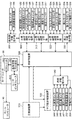
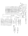
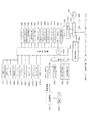
図6および図7は、パチンコ機10の電気的構成を示すブロック図である。パチンコ機10は、内枠開放スイッチ121と、前枠開放スイッチ141とを備える。内枠開放スイッチ121は、内枠120の開放状態を検知し、その検知信号を主制御装置510に出力する。前枠開放スイッチ141は、前枠140の開放状態を検知し、その検知信号を主制御装置510に出力する。 6 and 7 are block diagrams showing the electrical configuration of the pachinko machine 10. The pachinko machine 10 includes an inner frame opening switch 121 and a front frame opening switch 141. The inner frame opening switch 121 detects the open state of the inner frame 120 and outputs the detection signal to the main control device 510. The front frame opening switch 141 detects the open state of the front frame 140 and outputs the detection signal to the main control device 510.

パチンコ機10は、主制御装置510と遊技盤200との間を中継する回路基板として、図柄表示装置中継端子板250と、遊技盤中継端子板270とを備える。パチンコ機10は、遊技盤中継端子板270を介して主制御装置510に信号を出力する電気的構成として、第1始動口スイッチ271と、第2始動口スイッチ272と、普通図柄作動スイッチ273と、左入賞口スイッチ274と、カウントスイッチ276と、磁石センサ277と、電波センサ278とを備える。パチンコ機10は、遊技盤中継端子板270を介して主制御装置510からの信号に基づいて動作する電気的構成として、大入賞口ソレノイド282と、普電役物ソレノイド284と、賞球数表示装置286とを備える。パチンコ機10は、図柄表示装置中継端子板250を介して主制御装置510からの信号に基づいて動作する電気的構成として、第1特図表示装置251と、第2特図表示装置252と、第1特図保留数表示装置261と、第2特図保留数表示装置262と、普通図柄表示装置253と、普図保留数表示装置263とを備える。 The pachinko machine 10 includes a symbol display device relay terminal board 250 and a game board relay terminal board 270 as a circuit board that relays between the main control device 510 and the game board 200. The pachinko machine 10 has a first start port switch 271, a second start port switch 272, and a normal symbol operation switch 273 as an electrical configuration that outputs a signal to the main control device 510 via the game board relay terminal plate 270. , The left winning opening switch 274, the count switch 276, the magnet sensor 277, and the radio wave sensor 278 are provided. The pachinko machine 10 has a large winning opening solenoid 282, a general electric accessory solenoid 284, and a prize ball number display as an electrical configuration that operates based on a signal from the main control device 510 via the game board relay terminal plate 270. A device 286 is provided. The pachinko machine 10 has a first special figure display device 251 and a second special figure display device 252 as an electrical configuration that operates based on a signal from the main control device 510 via the symbol display device relay terminal plate 250. It includes a first special figure hold number display device 261, a second special figure hold number display device 262, a normal symbol display device 253, and a normal figure hold number display device 263.

第1始動口スイッチ271は、第1始動口241への入球を検知し、その検知信号を出力する。第2始動口スイッチ272は、第2始動口242への入球を検知し、その検知信号を出力する。普通図柄作動スイッチ273は、普通図柄作動ゲート243における遊技球の通過を検知し、その検知信号を出力する。左入賞口スイッチ274は、普通入賞口246への入球を検知し、その検知信号を出力する。カウントスイッチ276は、大入賞口248への入球を検知し、その検知信号を出力する。磁石センサ277は、パチンコ機10に対する磁石を用いた不正行為を検知し、その検知信号を出力する。電波センサ278は、パチンコ機10に対する電波を用いた不正行為を検知し、その検知信号を出力する。 The first start port switch 271 detects the entry of the ball into the first start port 241 and outputs the detection signal. The second start port switch 272 detects the entry of the ball into the second start port 242 and outputs the detection signal. The normal symbol operation switch 273 detects the passage of the game ball at the normal symbol operation gate 243 and outputs the detection signal. The left winning opening switch 274 detects the entry of a ball into the normal winning opening 246 and outputs the detection signal. The count switch 276 detects the entry of a ball into the large winning opening 248 and outputs the detection signal. The magnet sensor 277 detects fraudulent activity using a magnet against the pachinko machine 10 and outputs the detection signal. The radio wave sensor 278 detects fraudulent activity using radio waves against the pachinko machine 10 and outputs the detection signal.

大入賞口ソレノイド282は、主制御装置510からの制御信号に基づいて、大入賞口248を開閉する。普電役物ソレノイド284は、主制御装置510からの制御信号に基づいて、普通電動役物245を開閉する。賞球数表示装置286は、主制御装置510からの制御信号に基づいて、持ち球数に加算する賞球数を表示する。 The grand prize opening solenoid 282 opens and closes the grand prize opening 248 based on the control signal from the main control device 510. The general electric accessory solenoid 284 opens and closes the ordinary electric accessory 245 based on the control signal from the main control device 510. The prize ball number display device 286 displays the number of prize balls to be added to the number of balls held, based on the control signal from the main control device 510.

第1特図表示装置251は、主制御装置510からの制御信号に基づいて、第1特別図柄を表示する。第2特図表示装置252は、主制御装置510からの制御信号に基づいて、第2特別図柄を表示する。第1特図保留数表示装置261は、主制御装置510からの制御信号に基づいて、第1特別図柄に関する保留記憶の個数を表示する。第2特図保留数表示装置262は、主制御装置510からの制御信号に基づいて、第2特別図柄に関する保留記憶の個数を表示する。普通図柄表示装置253は、主制御装置510からの制御信号に基づいて、普通図柄を表示する。普図保留数表示装置263は、主制御装置510からの制御信号に基づいて、普通図柄に関する保留記憶の個数を表示する。 The first special figure display device 251 displays the first special symbol based on the control signal from the main control device 510. The second special symbol display device 252 displays the second special symbol based on the control signal from the main control device 510. The first special figure hold number display device 261 displays the number of hold storages related to the first special symbol based on the control signal from the main control device 510. The second special figure hold number display device 262 displays the number of hold storages related to the second special symbol based on the control signal from the main control device 510. The ordinary symbol display device 253 displays the ordinary symbol based on the control signal from the main control device 510. The normal figure hold number display device 263 displays the number of hold storages related to the normal symbol based on the control signal from the main control device 510.

サブ統合制御装置520は、主制御装置510からの片方向で主制御装置510と通信可能に構成されている。サブ統合制御装置520は、主制御装置510からの制御信号に基づいて、遊技の進行に応じて各種演出機器を制御する。スピーカ142は、サブ統合制御装置520からの制御信号に基づいて音声を出力するユーザインタフェースである。本実施形態では、サブ統合制御装置520は、スピーカ142から出力される音量を調節可能に構成された音量調整スイッチ522を備える。発光部144は、サブ統合制御装置520からの制御信号に基づいて発光するユーザインタフェースである。演出ボタン146は、擬似演出に対する遊技者の操作入力を検知するユーザインタフェースであり、その検知信号をサブ統合制御装置520に出力する。サブ統合制御装置520は、主制御装置510から受信される遊技に関する情報に基づいて、ユーザインタフェース(スピーカ142、発光部144、演出ボタン146および演出図柄表示装置230)を制御するユーザインタフェース制御装置である。サブ統合制御装置520は、更に、枠制御装置560からの片方向で枠制御装置560と通信可能に構成され、枠制御装置560から受信される情報に基づいて、ユーザインタフェース(スピーカ142、発光部144、演出ボタン146および演出図柄表示装置230)を制御する。
なお、主制御装置510と枠制御装置560とは双方向通信可能な構成でも良い。この場合には、枠制御装置560を介して外部から遊技の性能に関するデータを主制御装置510に送信できない構成、主制御装置が受信しない構成が考えられる。但し、これを必須要件とはしない双方向通信でも良い。
The sub-integrated control device 520 is configured to be able to communicate with the main control device 510 in one direction from the main control device 510. The sub-integrated control device 520 controls various production devices according to the progress of the game based on the control signal from the main control device 510. The speaker 142 is a user interface that outputs voice based on a control signal from the sub-integrated control device 520. In the present embodiment, the sub-integrated control device 520 includes a volume adjustment switch 522 configured so that the volume output from the speaker 142 can be adjusted. The light emitting unit 144 is a user interface that emits light based on a control signal from the sub-integrated control device 520. The effect button 146 is a user interface that detects the player's operation input for the simulated effect, and outputs the detection signal to the sub-integrated control device 520. The sub-integrated control device 520 is a user interface control device that controls a user interface (speaker 142, light emitting unit 144, effect button 146, and effect symbol display device 230) based on information about the game received from the main control device 510. is there. The sub-integrated control device 520 is further configured to be able to communicate with the frame control device 560 in one direction from the frame control device 560, and based on the information received from the frame control device 560, the user interface (speaker 142, light emitting unit). 144, the effect button 146, and the effect symbol display device 230) are controlled.
The main control device 510 and the frame control device 560 may be configured to be capable of bidirectional communication. In this case, it is conceivable that the data related to the performance of the game cannot be transmitted to the main control device 510 from the outside via the frame control device 560, or the main control device does not receive the data. However, two-way communication that does not require this as an essential requirement may be used.

演出図柄制御装置530は、サブ統合制御装置520と双方向で通信可能に構成されている。演出図柄制御装置530は、サブ統合制御装置520からの制御信号に基づいて、演出図柄表示装置230における演出図柄の変動表示をはじめとする擬似演出の表示を制御する。演出図柄表示装置230は、演出図柄制御装置530から受信したデータおよびコマンドに基づいて、演出図柄の変動表示をはじめとする擬似演出の表示を実行する。 The effect symbol control device 530 is configured to be able to communicate with the sub-integrated control device 520 in both directions. The effect symbol control device 530 controls the display of the pseudo effect including the variation display of the effect symbol on the effect symbol display device 230 based on the control signal from the sub-integrated control device 520. The effect symbol display device 230 executes a pseudo effect display including a variable display of the effect symbol based on the data and the command received from the effect symbol control device 530.

図7の説明に移り、枠制御装置560は、主制御装置510からの片方向で主制御装置510と通信可能に構成されている。枠制御装置560は、主制御装置510から送信される遊技に関する情報に基づいて、遊技者が遊技に使用可能な遊技球である持ち球の数を管理する。枠制御装置560は、持ち玉の管理に加え、遊技球の発射、回収および循環に関する処理を管理する。 Moving on to the description of FIG. 7, the frame control device 560 is configured to be able to communicate with the main control device 510 in one direction from the main control device 510. The frame control device 560 manages the number of balls held by the player, which are game balls that can be used for the game, based on the information about the game transmitted from the main control device 510. The frame control device 560 manages the processing related to the launch, collection, and circulation of the game ball, in addition to the management of the possession ball.

カードユニット80は、枠制御装置560と双方向で通信可能に構成されている。カードユニット80は、ユーザインタフェース810の他、遊技球等貸出装置850と、CRユニット860とを備える。遊技球等貸出装置850は、枠制御装置560およびCRユニット860と双方向で通信可能に構成されている。遊技球等貸出装置850は、カード挿入口820における記憶カードに記録されている持ち玉の情報、並びに、CRユニット860からの遊技球の貸し出しに関する情報に基づいて、遊技者に対する遊技球の貸し出しを枠制御装置560と協働して処理する。CRユニット860は、紙幣挿入口830に挿入された紙幣に基づく遊技球の貸し出しを制御する。CRユニット860は、パチンコ機10を管理するホールコンピュータ90と双方向で通信可能に構成されている。ホールコンピュータ90は、パチンコ機10における遊技に関する情報を、主制御装置510から、枠制御装置560およびカードユニット80を介して受信可能に構成されている。 The card unit 80 is configured to be able to communicate with the frame control device 560 in both directions. The card unit 80 includes a user interface 810, a game ball lending device 850, and a CR unit 860. The game ball rental device 850 is configured to be capable of bidirectional communication with the frame control device 560 and the CR unit 860. The game ball lending device 850 lends the game ball to the player based on the information on the ball held in the storage card at the card insertion slot 820 and the information on the lending of the game ball from the CR unit 860. It processes in cooperation with the frame control device 560. The CR unit 860 controls the lending of game balls based on the bills inserted in the bill insertion slot 830. The CR unit 860 is configured to be capable of bidirectional communication with the hall computer 90 that manages the pachinko machine 10. The hall computer 90 is configured to be able to receive information about the game in the pachinko machine 10 from the main control device 510 via the frame control device 560 and the card unit 80.

パチンコ機10は、枠制御装置560と内枠120との間を中継する回路基板として、操作部中継端子板160と、発射操作部中継端子板180と、発射装置中継端子板312と、研磨装置中継端子板322と、揚上中継端子板332と、内枠中継端子板342とを備える。パチンコ機10は、操作部中継端子板160を介して枠制御装置560と信号をやり取りする電気的構成として、計数スイッチ162と、持ち球数表示装置164とを備える。 The pachinko machine 10 has an operation unit relay terminal plate 160, a launch operation unit relay terminal plate 180, a launcher relay terminal plate 312, and a polishing device as circuit boards that relay between the frame control device 560 and the inner frame 120. A relay terminal board 322, a lifting relay terminal board 332, and an inner frame relay terminal board 342 are provided. The pachinko machine 10 includes a counting switch 162 and a ball holding number display device 164 as an electrical configuration for exchanging signals with the frame control device 560 via the operation unit relay terminal plate 160.

パチンコ機10は、発射操作部中継端子板180を介して枠制御装置560と信号をやり取りする電気的構成として、固定解除ソレノイド182と、発射強度固定スイッチ184と、ハンドルボリューム185と、タッチスイッチ186と、発射停止スイッチ187とを備える。パチンコ機10は、発射装置中継端子板312を介して枠制御装置560と信号をやり取りする電気的構成として、球送センサ314と、発射入口センサ315と、発射モータ316と、球送ソレノイド317とを備える。 The pachinko machine 10 has an electrical configuration for exchanging signals with the frame control device 560 via the firing operation unit relay terminal plate 180, such as a fixing release solenoid 182, a firing strength fixing switch 184, a handle volume 185, and a touch switch 186. And a launch stop switch 187. The pachinko machine 10 includes a ball feed sensor 314, a launch inlet sensor 315, a launch motor 316, and a ball feed solenoid 317 as an electrical configuration for exchanging signals with the frame control device 560 via the launch device relay terminal plate 312. To be equipped with.

パチンコ機10は、研磨装置中継端子板322を介して信号をやり取りする電気的構成として、カセットスイッチ324と、研磨モータセンサ325と、カセットモータ326と、研磨モータ327とを備える。パチンコ機10は、揚上中継端子板332を介して枠制御装置560と信号をやり取りする電気的構成として、揚上モータ334と、揚上入口センサ336と、揚上モータ監視センサ338とを備える。 The pachinko machine 10 includes a cassette switch 324, a polishing motor sensor 325, a cassette motor 326, and a polishing motor 327 as an electrical configuration for exchanging signals via a polishing device relay terminal plate 322. The pachinko machine 10 includes a lifting motor 334, a lifting inlet sensor 336, and a lifting motor monitoring sensor 338 as an electrical configuration for exchanging signals with the frame control device 560 via the lifting relay terminal plate 332. ..

パチンコ機10は、内枠中継端子板342を介して枠制御装置560に信号を出力する電気的構成として、入賞球センサ344と、アウト球センサ345と、適正量センサ346と、満タンセンサ347と、夜間監視装置352とを備える。パチンコ機10は、内枠中継端子板342を介して枠制御装置560からの信号に基づいて動作する電気的構成として、警報スピーカ354を備える。 The pachinko machine 10 has a winning ball sensor 344, an out ball sensor 345, an appropriate amount sensor 346, and a full tank sensor 347 as an electrical configuration that outputs a signal to the frame control device 560 via the inner frame relay terminal plate 342. , A night monitoring device 352 is provided. The pachinko machine 10 includes an alarm speaker 354 as an electrical configuration that operates based on a signal from the frame control device 560 via the inner frame relay terminal plate 342.

計数スイッチ162は、パチンコ機10で管理している持ち球に関する情報をカードユニット80の記録カードに移行させる遊技者の操作入力を検知し、その検知信号を枠制御装置560に出力する。持ち球数表示装置164は、枠制御装置560からの制御信号に基づいて、枠制御装置560で管理している持ち球の数を表示する。 The counting switch 162 detects the operation input of the player who transfers the information about the ball held by the pachinko machine 10 to the recording card of the card unit 80, and outputs the detection signal to the frame control device 560. The ball holding number display device 164 displays the number of balls held by the frame control device 560 based on the control signal from the frame control device 560.

固定解除ソレノイド182は、枠制御装置560からの制御信号に基づいて、ハンドル150における固定ボタン154による回転部152の固定を解除可能に構成されている。本実施形態では、固定解除ソレノイド182は、回転部152に係合している固定ボタン154の係合部分を押圧することによって、固定ボタン154による回転部152との係合を解除可能に構成されている。固定解除ソレノイド182は、発射強度固定手段による発射強度の固定を解除する固定解除手段として機能する。 The fixing release solenoid 182 is configured to be able to release the fixing of the rotating portion 152 by the fixing button 154 on the handle 150 based on the control signal from the frame control device 560. In the present embodiment, the fixing release solenoid 182 is configured to be able to release the engagement of the fixing button 154 with the rotating portion 152 by pressing the engaging portion of the fixing button 154 engaged with the rotating portion 152. ing. The fixing release solenoid 182 functions as a fixing release means for releasing the fixation of the firing intensity by the firing strength fixing means.

発射強度固定スイッチ184は、ハンドル150における固定ボタン154による回転部152の固定を検知し、その検知信号を枠制御装置560に出力する。ハンドルボリューム185は、ハンドル150における回転部152の回転位置を発射強度として検知し、その検知信号を枠制御装置560に出力する。タッチスイッチ186は、ハンドル150に対する遊技者による接触を検知し、その検知信号を枠制御装置560に出力する。発射停止スイッチ187は、遊技球の発射を停止する遊技者の操作入力を検知し、その検知信号を枠制御装置560に出力する。 The firing intensity fixing switch 184 detects the fixing of the rotating portion 152 by the fixing button 154 on the handle 150, and outputs the detection signal to the frame control device 560. The handle volume 185 detects the rotational position of the rotating portion 152 on the handle 150 as the firing intensity, and outputs the detection signal to the frame control device 560. The touch switch 186 detects the player's contact with the handle 150 and outputs the detection signal to the frame control device 560. The launch stop switch 187 detects the operation input of the player who stops the launch of the game ball, and outputs the detection signal to the frame control device 560.

球送センサ314は、発射装置310に送り込まれる遊技球を検知し、その検出信号を枠制御装置560に出力する。発射入口センサ315は、発射装置310から発射され導入口214を通過する遊技球を検知し、その検出信号を枠制御装置560に出力する。発射モータ316は、枠制御装置560からの制御信号に基づいて、遊技球を発射する。球送ソレノイド317は、枠制御装置560からの制御信号に基づいて、発射可能な位置に遊技球を送り込む。 The ball feeding sensor 314 detects the game ball sent to the launching device 310, and outputs the detection signal to the frame control device 560. The launch inlet sensor 315 detects a game ball launched from the launch device 310 and passes through the introduction port 214, and outputs the detection signal to the frame control device 560. The launch motor 316 launches a game ball based on a control signal from the frame control device 560. The ball feed solenoid 317 feeds the game ball to a position where it can be launched based on the control signal from the frame control device 560.

カセットスイッチ324は、遊技球を研磨する研磨布を収容する研磨布カセット(図示しない)が研磨装置320に組み込まれていることを検知し、その検知信号を枠制御装置560に出力する。研磨モータセンサ325は、研磨モータ327の動作を検知し、その検知信号を枠制御装置560に出力する。カセットモータ326は、枠制御装置560からの制御信号に基づいて、研磨布カセット(図示しない)における研磨布を巻き取る。研磨モータ327は、枠制御装置560からの制御信号に基づいて、遊技球を研磨布に押し付けることによって遊技球を研磨する。 The cassette switch 324 detects that a polishing pad cassette (not shown) accommodating the polishing pad for polishing the game ball is incorporated in the polishing device 320, and outputs the detection signal to the frame control device 560. The polishing motor sensor 325 detects the operation of the polishing motor 327 and outputs the detection signal to the frame control device 560. The cassette motor 326 winds up the polishing pad in the polishing pad cassette (not shown) based on the control signal from the frame control device 560. The polishing motor 327 polishes the game ball by pressing the game ball against the polishing cloth based on the control signal from the frame control device 560.

揚上モータ334は、枠制御装置560からの制御信号に基づいて、揚上装置330から発射装置310へと遊技球を送り出す。揚上入口センサ336は、研磨装置320から揚上装置330に送り込まれる遊技球を検知し、その検知信号を枠制御装置560に出力する。揚上モータ監視センサ338は、揚上モータ334の動作を検知し、その検知信号を枠制御装置560に出力する。 The lifting motor 334 sends out the game ball from the lifting device 330 to the launching device 310 based on the control signal from the frame control device 560. The lifting inlet sensor 336 detects a game ball sent from the polishing device 320 to the lifting device 330, and outputs the detection signal to the frame control device 560. The lifting motor monitoring sensor 338 detects the operation of the lifting motor 334 and outputs the detection signal to the frame control device 560.

入賞球センサ344は、遊技盤200において入賞した後に遊技盤200から研磨装置320へと回収される遊技球を検知し、その検知信号を出力する。アウト球センサ345は、遊技盤200において回収口218を通過して遊技盤200から研磨装置320へと回収される遊技球を検知し、その検知信号を出力する。適正量センサ346は、揚上装置330から発射装置310へと移送される遊技球が適正量であることを検知し、その検知信号を出力する。満タンセンサ347は、揚上装置330から発射装置310へと移送される遊技球が過剰であることを検知し、その検知信号を出力する。夜間監視装置352は、パチンコ機10の稼動時間外(夜間)にバックアップ電源によって作動可能に構成され、内枠120の開放を検知し、その検知信号を出力する。夜間監視スイッチ夜間監視装置352は、内枠開放スイッチ121および前枠開放スイッチ141からの出力信号に基づいて内枠120の開放を検知してもよいし、内枠開放スイッチ121および前枠開放スイッチ141とは異なるスイッチからの信号に基づいて内枠120の開放を検知してもよい。本実施形態では、枠制御装置560は、夜間監視装置352からの検知信号に基づく内枠120の開放回数を示す情報を、パチンコ機10の電源投入時にホールコンピュータ90へと出力可能に構成されている。警報スピーカ354は、枠制御装置560からの制御信号に基づいて音声を出力する。本実施形態では、枠制御装置560は、夜間監視装置352によって内枠120の開放が検知された場合、警報スピーカ354から警報を出力する制御処理を実行する。 The winning ball sensor 344 detects a game ball collected from the game board 200 to the polishing device 320 after winning a prize in the game board 200, and outputs the detection signal. The out-ball sensor 345 detects a game ball that has passed through the collection port 218 in the game board 200 and is collected from the game board 200 to the polishing device 320, and outputs a detection signal thereof. The appropriate amount sensor 346 detects that the amount of the game ball transferred from the lifting device 330 to the launching device 310 is an appropriate amount, and outputs the detection signal. The full tank sensor 347 detects that the number of game balls transferred from the lifting device 330 to the launching device 310 is excessive, and outputs the detection signal. The night monitoring device 352 is configured to be operable by a backup power source outside the operating hours (night) of the pachinko machine 10, detects the opening of the inner frame 120, and outputs the detection signal. Night monitoring switch The night monitoring device 352 may detect the opening of the inner frame 120 based on the output signals from the inner frame opening switch 121 and the front frame opening switch 141, or the inner frame opening switch 121 and the front frame opening switch. The opening of the inner frame 120 may be detected based on a signal from a switch different from 141. In the present embodiment, the frame control device 560 is configured to be able to output information indicating the number of times the inner frame 120 is opened based on the detection signal from the night monitoring device 352 to the hall computer 90 when the pachinko machine 10 is turned on. There is. The alarm speaker 354 outputs voice based on the control signal from the frame control device 560. In the present embodiment, the frame control device 560 executes a control process for outputting an alarm from the alarm speaker 354 when the opening of the inner frame 120 is detected by the night monitoring device 352.

パチンコ機10は、普通図柄作動ゲート243への入球に基づいて、普通図柄に関する当否判断を実施する。パチンコ機10は、普通図柄に関する当否の判断結果に基づいて、普通図柄表示装置253において普通図柄を用いた変動表示を実施する。普通図柄に関する当否の判断結果が当りである場合、パチンコ機10は、普通図柄表示装置253において当り図柄である普通図柄を確定表示するとともに、所定期間、普通電動役物245を開放する。これによって、第2始動口242への入賞が可能となる。 The pachinko machine 10 determines whether or not the normal symbol is correct or not based on the ball entering the normal symbol operating gate 243. The pachinko machine 10 performs variable display using the normal symbol on the normal symbol display device 253 based on the result of determining whether the normal symbol is correct or not. When the result of determining whether or not the normal symbol is correct is a hit, the pachinko machine 10 confirms and displays the normal symbol, which is the hit symbol, on the normal symbol display device 253, and opens the ordinary electric accessory 245 for a predetermined period. As a result, it is possible to win a prize in the second starting port 242.

パチンコ機10は、第1始動口241への入球に基づいて、第1特別図柄に関する当否判断を実施する。パチンコ機10は、第1特別図柄に関する当否の判断結果に基づいて、第1特図表示装置251において第1特別図柄を用いた変動表示を実施する。パチンコ機10は、第1特図表示装置251において第1特別図柄を用いた変動表示に合わせて、演出図柄表示装置230において演出図柄を用いた擬似演出を実施する。第1特別図柄に関する当否の判断結果が大当りである場合、パチンコ機10は、第1特図表示装置251において大当り図柄である第1特別図柄を確定表示した後、所定の動作パターンで大入賞口248を開放する大当り遊技状態(特別遊技状態)に移行する。これによって、大入賞口248への入賞が可能となる。主制御装置510は、第1始動口241への遊技球の入球に起因して、大当り遊技状態を実行するか否かを判断する当否判断手段として機能する。 The pachinko machine 10 determines whether or not the first special symbol is correct or not based on the ball entering the first starting port 241. The pachinko machine 10 performs variable display using the first special symbol on the first special symbol display device 251 based on the result of determining whether or not the first special symbol is correct. The pachinko machine 10 performs a simulated effect using the effect symbol on the effect symbol display device 230 in accordance with the variable display using the first special symbol on the first special symbol display device 251. When the result of determining whether or not the first special symbol is a big hit is a big hit, the pachinko machine 10 confirms and displays the first special symbol, which is the big hit symbol, on the first special symbol display device 251 and then confirms and displays the first special symbol, which is a big hit symbol, and then performs a big winning opening in a predetermined operation pattern. It shifts to the jackpot game state (special game state) in which 248 is released. As a result, it is possible to win a prize in the large winning opening 248. The main control device 510 functions as a hit / fail determination means for determining whether or not to execute the jackpot game state due to the entry of the game ball into the first start port 241.

パチンコ機10は、第2始動口242への入球に基づいて、第2特別図柄に関する当否判断を実施する。パチンコ機10は、第2特別図柄に関する当否の判断結果に基づいて、第2特図表示装置252において第2特別図柄を用いた変動表示を実施する。パチンコ機10は、第2特図表示装置252において第2特別図柄を用いた変動表示に合わせて、演出図柄表示装置230において演出図柄を用いた擬似演出を実施する。第2特別図柄に関する当否の判断結果が大当りである場合、パチンコ機10は、第2特図表示装置252において大当り図柄である第2特別図柄を確定表示した後、大当り遊技状態に移行する。これによって、大入賞口248への入賞が可能となる。主制御装置510は、第2始動口242への遊技球の入球に起因して、大当り遊技状態を実行するか否かを判断する当否判断手段として機能する。 The pachinko machine 10 determines whether or not the second special symbol is correct or not based on the ball entering the second starting port 242. The pachinko machine 10 performs variable display using the second special symbol on the second special symbol display device 252 based on the result of determining whether the second special symbol is correct or not. The pachinko machine 10 performs a simulated effect using the effect symbol on the effect symbol display device 230 in accordance with the variable display using the second special symbol on the second special symbol display device 252. When the result of determining whether the second special symbol is correct or not is a big hit, the pachinko machine 10 confirms and displays the second special symbol, which is the big hit symbol, on the second special symbol display device 252, and then shifts to the big hit game state. As a result, it is possible to win a prize in the large winning opening 248. The main control device 510 functions as a hit / fail determination means for determining whether or not to execute the jackpot game state due to the entry of the game ball into the second starting port 242.

パチンコ機10は、大当り遊技を実施している間、第1特別図柄および第2特別図柄に関する当否の判断を停止する。パチンコ機10は、第1特別図柄および第2特別図柄の両方に関する保留記憶がある場合、第2特別図柄に関する保留記憶の当否判断を優先的に実施する。大当り遊技状態を終えた後、パチンコ機10は、所定の条件に応じて、通常遊技状態と、時短遊技状態と、確変時短遊技状態とのいずれかの状態に移行する。通常遊技状態は、通常の当選確率で普通図柄、第1特別図柄および第2特別図柄の当否判断を実施する遊技状態である。時短遊技状態は、第1特別図柄、第2特別図柄および普通図柄を変動表示させる時間を通常遊技状態より短縮した上で、普通電動役物245の平均開放時間を通常遊技状態より延長する遊技状態である。確変時短遊技状態は、時短遊技状態の動作に加え、通常遊技状態より高い当選確率で第1特別図柄および第2特別図柄の当否判断を実施する遊技状態である。主制御装置510は、所定の条件(例えば、所定の大当り図柄で当選)を満たす場合、大当り遊技状態の終了後、普通電動役物245の1回あたりの開放時間を通常遊技状態より延長する開放延長状態(時短遊技状態および確変時短遊技状態)を実行する開放延長実行手段として動作する。 While the pachinko machine 10 is performing the jackpot game, the pachinko machine 10 stops determining whether or not the first special symbol and the second special symbol are correct or not. When the pachinko machine 10 has a hold memory for both the first special symbol and the second special symbol, the pachinko machine 10 preferentially determines whether or not the hold memory for the second special symbol is correct or not. After finishing the jackpot gaming state, the pachinko machine 10 shifts to one of a normal gaming state, a time-saving gaming state, and a probabilistic time-saving gaming state, depending on a predetermined condition. The normal gaming state is a gaming state in which the winning / failing of the normal symbol, the first special symbol, and the second special symbol is determined with a normal winning probability. The time-saving game state is a game state in which the time for variable display of the first special symbol, the second special symbol, and the normal symbol is shortened from the normal game state, and the average opening time of the normal electric accessory 245 is extended from the normal game state. Is. The probabilistic time-saving gaming state is a gaming state in which, in addition to the operation of the time-saving gaming state, the winning / failing judgment of the first special symbol and the second special symbol is performed with a higher winning probability than the normal gaming state. When the main control device 510 satisfies a predetermined condition (for example, winning with a predetermined jackpot symbol), after the jackpot gaming state ends, the opening time of the normal electric accessory 245 is extended from the normal gaming state. It operates as an open extension execution means for executing an extension state (time saving game state and probability variation time saving game state).

通常遊技状態では、第1始動口241が第1の遊技領域211に位置することから、第1の遊技領域211に遊技球を発射して遊技を実施すること(いわゆる「左打ち」)が推奨される。大当り遊技状態では、大入賞口248が第2の遊技領域212に位置することから、第2の遊技領域212に遊技球を発射して遊技を実施すること(いわゆる「右打ち」)が推奨される。時短遊技状態および確変時短遊技状態では、普通図柄作動ゲート243および第2始動口242が第2の遊技領域212に位置することから、第2の遊技領域212に遊技球を発射して遊技を実施すること(右打ち)が推奨される。 In the normal gaming state, since the first starting port 241 is located in the first gaming area 211, it is recommended to launch the gaming ball into the first gaming area 211 to perform the game (so-called "left-handed"). Will be done. In the big hit game state, since the big winning opening 248 is located in the second game area 212, it is recommended to shoot the game ball in the second game area 212 to perform the game (so-called "right-handed"). To. In the time-saving game state and the probability variation time-saving game state, since the normal symbol operating gate 243 and the second starting port 242 are located in the second game area 212, the game ball is fired in the second game area 212 to perform the game. It is recommended to do (right-handed).

〔当選確率設定処理〕
本実施形態のパチンコ機10には、図示しない電源基板が設けられ、図示しない電源SWにより電源をON又はOFFに切り替える。
また、図6に示すように、主制御装置510には、RWMクリアスイッチ290及び設定キースイッチ291が設けられる。RWMクリアスイッチ290は、主として、主制御装置510に内蔵されたRWM(RAM)に記憶された遊技情報等をクリアする際に操作される。なお、RWMクリアスイッチ290は、枠制御装置560や電源基板に設けてもよい。
設定キースイッチ291は、鍵穴に挿入した鍵を一方向へ回転させることでONとなる鍵スイッチ機構である。パチンコ機10は、ホール従業員等の操作によって大当たり確率の設定を変更可能な設定機能を有する遊技機であり、ホール従業員等は、設定キースイッチ291をONにした状態で電源を投入することにより、大当たり確率の設定変更及び設定確認を行うことができる。なお、RWMクリアスイッチ290は、大当たり確率の設定変更を行う際にも操作される。
[Winning probability setting process]
The pachinko machine 10 of the present embodiment is provided with a power supply board (not shown), and the power supply is switched ON or OFF by a power supply SW (not shown).
Further, as shown in FIG. 6, the main control device 510 is provided with an RWM clear switch 290 and a setting key switch 291. The RWM clear switch 290 is mainly operated when clearing game information or the like stored in the RWM (RAM) built in the main control device 510. The RWM clear switch 290 may be provided on the frame control device 560 or the power supply board.
The setting key switch 291 is a key switch mechanism that is turned on by rotating the key inserted in the keyhole in one direction. The pachinko machine 10 is a gaming machine having a setting function capable of changing the setting of the jackpot probability by the operation of a hall employee or the like, and the hall employee or the like turns on the power with the setting key switch 291 turned on. Therefore, the setting of the jackpot probability can be changed and the setting can be confirmed. The RWM clear switch 290 is also operated when changing the setting of the jackpot probability.

パチンコ機10は、主制御装置510のRWMの段階設定値格納領域に対し、当否判断での大当たり確率に応じて6段階に分けられた段階設定値1〜6を設定する。そして、主制御装置510は、段階設定値格納領域に格納された段階設定値に基づき、第一特図又は第二特図の当否判断で用いる当否判断テーブルを決定する。
本実施形態では、段階設定値格納領域に格納された段階設定値が「1」のとき、通常状態での大当たり確率(以下、「設定確率」ということもある。)は1/300に設定され、確変状態での大当たり確率は1/30に設定される。また、段階設定値格納領域に段階設定値が「2」のとき、通常状態での大当たり確率は1/290に設定されると共に、確変状態での大当たり確率は1/29に設定され、段階設定値格納領域に段階設定値が「3」のとき、通常状態での大当たり確率は1/280に設定されると共に、確変状態での大当たり確率は1/28に設定される。
同様に、段階設定値が「4」に設定されたとき、通常状態での大当たり確率は1/270に設定されると共に、確変状態での大当たり確率は1/27に設定され、段階設定値が「5」に設定されたとき、通常状態での大当たり確率は1/260に設定されると共に、確変状態での大当たり確率は1/26に設定され、段階設定値が「6」に設定されたとき、通常状態での大当たり確率は1/250に設定されると共に、確変状態での大当たり確率は1/25に設定される。
The pachinko machine 10 sets the stage setting values 1 to 6 divided into 6 stages according to the jackpot probability in the hit / fail judgment in the stage setting value storage area of the RWM of the main control device 510. Then, the main control device 510 determines the pass / fail determination table used in the pass / fail determination of the first special figure or the second special figure based on the stage set value stored in the stage set value storage area.
In the present embodiment, when the stage setting value stored in the stage setting value storage area is "1", the jackpot probability in the normal state (hereinafter, also referred to as "setting probability") is set to 1/300. , The jackpot probability in the probabilistic state is set to 1/30. Further, when the stage setting value is "2" in the stage setting value storage area, the jackpot probability in the normal state is set to 1/290, and the jackpot probability in the probability variation state is set to 1/29, and the stage setting is performed. When the stage setting value is "3" in the value storage area, the jackpot probability in the normal state is set to 1/280, and the jackpot probability in the probability variation state is set to 1/28.
Similarly, when the step setting value is set to "4", the jackpot probability in the normal state is set to 1/270, the jackpot probability in the probability variation state is set to 1/27, and the step setting value is set. When set to "5", the jackpot probability in the normal state is set to 1/260, the jackpot probability in the probability variation state is set to 1/26, and the step setting value is set to "6". At this time, the jackpot probability in the normal state is set to 1/250, and the jackpot probability in the probability variation state is set to 1/25.

なお、本実施形態において、段階設定値は、通常状態での大当たり確率と確変状態での大当たり確率とが連動しているが、これに限られるものではない。例えば、パチンコ機10は、通常状態での大当たり確率及び確変状態での大当たり確率の何れか一方を段階設定値に関係なく一定としつつ、何れか他方のみが段階設定値に応じて変更されるものであってもよい。また、パチンコ機10は、段階設定値を変更した場合に、通常状態での大当たり確率及び確変状態での大当たり確率の何れか一方を上昇させつつ、何れか他方を低下させてもよい。 In the present embodiment, the step setting value is linked to the jackpot probability in the normal state and the jackpot probability in the probability variation state, but is not limited to this. For example, in the pachinko machine 10, one of the jackpot probability in the normal state and the jackpot probability in the probabilistic state is constant regardless of the stage setting value, and only one of them is changed according to the stage setting value. It may be. Further, when the stage setting value is changed, the pachinko machine 10 may increase either the jackpot probability in the normal state or the jackpot probability in the probabilistic state while decreasing the other.

〔メインルーチン〕
図8は、主制御装置510が実行する「メインルーチン」を示すフローチャートである。主制御装置510は、図8の「メインルーチン」を2ms(ミリ秒)周期の割り込み信号に基づいて開始する。割り込み信号の周期は、4msであってもよいし、他の周期であってもよい。
[Main routine]
FIG. 8 is a flowchart showing a “main routine” executed by the main control device 510. The main controller 510 starts the "main routine" of FIG. 8 based on an interrupt signal having a period of 2 ms (milliseconds). The period of the interrupt signal may be 4 ms or another period.

メインルーチンを開始した後、主制御装置510は、今回の割り込み信号が正常な割り込み信号であるか否かを判断する(ステップS100)。今回の割り込み信号が正常な割り込みでない場合(ステップS100:「NO」)、主制御装置510は、各種の制御変数を初期値に設定する初期設定処理(ステップS115)を実行する。その後、主制御装置510は、次回の割り込み信号を受信するまで、各種の乱数を更新する初期値乱数更新処理を繰り返し実行する(ステップS111)。 After starting the main routine, the main control device 510 determines whether or not the interrupt signal this time is a normal interrupt signal (step S100). When the interrupt signal this time is not a normal interrupt (step S100: “NO”), the main control device 510 executes an initial setting process (step S115) for setting various control variables to initial values. After that, the main control device 510 repeatedly executes the initial value random number update process for updating various random numbers until the next interrupt signal is received (step S111).

今回の割り込み信号が正常な割り込み信号である場合(ステップS100:「YES」)、主制御装置510は、各種の乱数を更新する初期値乱数更新処理を実行する(ステップS101)。その後、主制御装置510は、第1特別図柄および第2特別図柄に関する当否判断に用いる乱数である大当り決定用乱数を更新する(ステップS102)。その後、主制御装置510は、第1特別図柄および第2特別図柄に関する大当り図柄の決定に用いる乱数である大当り図柄決定用乱数を更新する(ステップS103)。その後、主制御装置510は、普通図柄に関する当否判断に用いる乱数である当り決定用乱数を更新する(ステップS104)。その後、主制御装置510は、第1特別図柄および第2特別図柄の変動時間に関する判断に用いる乱数であるリーチ判断用乱数および変動パターン決定用乱数を更新する(ステップS105,S106)。 When the interrupt signal this time is a normal interrupt signal (step S100: “YES”), the main controller 510 executes an initial value random number update process for updating various random numbers (step S101). After that, the main control device 510 updates the big hit determination random number, which is a random number used for determining whether or not the first special symbol and the second special symbol are correct (step S102). After that, the main control device 510 updates the big hit symbol determination random number, which is a random number used for determining the jackpot symbol related to the first special symbol and the second special symbol (step S103). After that, the main control device 510 updates the hit determination random number, which is a random number used for determining whether or not the normal symbol is correct (step S104). After that, the main control device 510 updates the reach determination random number and the variation pattern determination random number, which are random numbers used for determining the fluctuation time of the first special symbol and the second special symbol (steps S105 and S106).

乱数を更新した後(ステップS101〜S106)、主制御装置510は、主制御装置510に接続された各スイッチ類による遊技球の検出を確認する入賞確認処理(ステップS107)を実行する。その後、主制御装置510は、普通図柄、第1特別図柄および第2特別図柄に関する当否を判断する当否判断処理(ステップS108)を実行する。当否判断処理(ステップS108)において、主制御装置510は、第1始動口241および第2始動口242への遊技球の入球に起因して、大当り遊技状態を実行するか否かを判断する当否判断手段として動作する。 After updating the random numbers (steps S101 to S106), the main control device 510 executes a winning confirmation process (step S107) for confirming the detection of the game ball by the switches connected to the main control device 510. After that, the main control device 510 executes a pass / fail determination process (step S108) for determining whether the normal symbol, the first special symbol, and the second special symbol are correct or not. In the hit / fail determination process (step S108), the main control device 510 determines whether or not to execute the jackpot game state due to the entry of the game ball into the first start port 241 and the second start port 242. It operates as a pass / fail judgment means.

当否判断処理(ステップS108)を実行した後、主制御装置510は、パチンコ機10の各部に対する信号を出力する各出力処理(ステップS109)を実行する。各出力処理(ステップS109)では、遊技の進行状態、磁石センサ277および電波センサ278に基づく不正行為の検知状態、並びに、内枠開放スイッチ121および前枠開放スイッチ141に基づく開放状態に応じて、サブ統合制御装置520、枠制御装置560、大入賞口ソレノイド282などに対して、並びに、枠制御装置560およびカードユニット80を介してホールコンピュータ90に対して、主制御装置510は、各種の信号を出力する。その後、主制御装置510は、パチンコ機10に対する不正行為を監視する不正監視処理(ステップS110)を実行する。その後、主制御装置510は、次回の割り込み信号を受信するまで、各種の乱数を更新する初期値乱数更新処理を繰り返し実行する(ステップS111)。 After executing the pass / fail determination process (step S108), the main control device 510 executes each output process (step S109) that outputs a signal to each part of the pachinko machine 10. In each output process (step S109), depending on the progress state of the game, the detection state of fraud based on the magnet sensor 277 and the radio wave sensor 278, and the open state based on the inner frame opening switch 121 and the front frame opening switch 141, The main control device 510 provides various signals to the sub-integrated control device 520, the frame control device 560, the grand prize opening solenoid 282, etc., and to the hall computer 90 via the frame control device 560 and the card unit 80. Is output. After that, the main control device 510 executes a fraud monitoring process (step S110) for monitoring fraudulent acts on the pachinko machine 10. After that, the main control device 510 repeatedly executes the initial value random number update process for updating various random numbers until the next interrupt signal is received (step S111).

〔始動入賞処理〕
図9は、主制御装置510が実行する「始動入賞処理」を示すフローチャートである。図9の「始動入賞処理」は、図8の入賞確認処理(ステップS107)に含まれるサブルーチンである。
[Starting prize processing]
FIG. 9 is a flowchart showing a “starting winning process” executed by the main control device 510. The “starting winning process” of FIG. 9 is a subroutine included in the winning confirmation process (step S107) of FIG.

始動入賞処理を開始した後、主制御装置510は、第1始動口スイッチ271からの検知信号に基づいて第1始動口241への入球を検知したか否かを判断する(ステップS200)。第1始動口241への入球を検知した場合(ステップS200:「YES」)、主制御装置510は、第1特別図柄に関する保留記憶が上限数(本実施形態では4つ)未満であるか否かを判断する(ステップS201)。第1特別図柄に関する保留記憶が上限数未満である場合、第1始動口241への入球に応じて抽出した大当り決定用乱数、大当り図柄決定用乱数、リーチ判断用乱数、変動パターン決定用乱数を、第1特別図柄に関する保留記憶として記憶するとともに、第1特別図柄に関する保留記憶の数を示す第1保留記憶カウンタをインクリメントする(ステップS202)。その後、主制御装置510は、第1特別図柄に関する保留記憶の内容を先読みする先読判断処理(ステップS203)を実行する。その後、主制御装置510は、先読判断処理(ステップS203)の判断結果を示す第1先読判断コマンドをサブ統合制御装置520に送信する(ステップS204)。その後、主制御装置510は、第1保留記憶カウンタの値を示す第1保留数指示コマンドをサブ統合制御装置520に送信する(ステップS205)。サブ統合制御装置520は、第1先読判断コマンドおよび第1保留数指示コマンドに基づいて、演出図柄表示装置230において表示される擬似演出を制御する。具体的には、サブ統合制御装置520は、第1保留数指示コマンドに基づいて、演出図柄表示装置230に表示される第1特別図柄に関する保留記憶の数を示す第1保留図柄の表示数を増加させ、第1先読判断コマンドに基づいて、第1保留図柄を大当り期待度に応じた態様に変化させる。 After starting the start winning process, the main control device 510 determines whether or not the ball has been detected in the first start port 241 based on the detection signal from the first start port switch 271 (step S200). When it is detected that the ball has entered the first starting port 241 (step S200: "YES"), does the main control device 510 have less than the upper limit number (4 in this embodiment) of the reserved memory related to the first special symbol? It is determined whether or not (step S201). When the number of reserved memories related to the first special symbol is less than the upper limit, a random number for determining a jackpot, a random number for determining a jackpot symbol, a random number for determining reach, and a random number for determining a fluctuation pattern extracted according to the entry into the first starting port 241. Is stored as the hold storage related to the first special symbol, and the first hold storage counter indicating the number of hold storages related to the first special symbol is incremented (step S202). After that, the main control device 510 executes a pre-reading determination process (step S203) for pre-reading the contents of the reserved storage related to the first special symbol. After that, the main control device 510 transmits a first read-ahead determination command indicating the determination result of the look-ahead determination process (step S203) to the sub-integrated control device 520 (step S204). After that, the main control device 510 transmits a first hold number instruction command indicating the value of the first hold storage counter to the sub-integrated control device 520 (step S205). The sub-integrated control device 520 controls the pseudo effect displayed on the effect symbol display device 230 based on the first read-ahead determination command and the first hold number instruction command. Specifically, the sub-integrated control device 520 determines the number of display numbers of the first hold symbol indicating the number of hold storages related to the first special symbol displayed on the effect symbol display device 230 based on the first hold number instruction command. The number is increased, and the first reserved symbol is changed to a mode according to the jackpot expectation degree based on the first look-ahead determination command.

第1始動口241に関する処理を終えた後(ステップS200:「NO」、ステップS201:「NO」、ステップS205)、主制御装置510は、第2始動口スイッチ272からの検知信号に基づいて第2始動口242への入球を検知したか否かを判断する(ステップS206)。第2始動口242への入球を検知した場合(ステップS206:「YES」)、主制御装置510は、第2特別図柄に関する保留記憶が上限数(本実施形態では4つ)未満であるか否かを判断する(ステップS207)。第2特別図柄に関する保留記憶が上限数未満である場合、第2始動口242への入球に応じて抽出した大当り決定用乱数、大当り図柄決定用乱数、リーチ判断用乱数、変動パターン決定用乱数を、第2特別図柄に関する保留記憶として記憶するとともに、第2特別図柄に関する保留記憶の数を示す第2保留記憶カウンタをインクリメントする(ステップS208)。その後、主制御装置510は、第2特別図柄に関する保留記憶の内容を先読みする先読判断処理(ステップS209)を実行する。その後、主制御装置510は、先読判断処理(ステップS209)の判断結果を示す第2先読判断コマンドをサブ統合制御装置520に送信する(ステップS210)。その後、主制御装置510は、第2保留記憶カウンタの値を示す第2保留数指示コマンドをサブ統合制御装置520に送信する(ステップS211)。サブ統合制御装置520は、第2先読判断コマンドおよび第2保留数指示コマンドに基づいて、演出図柄表示装置230において表示される擬似演出を制御する。具体的には、サブ統合制御装置520は、第2保留数指示コマンドに基づいて、演出図柄表示装置230に表示される第2特別図柄に関する保留記憶の数を示す第2保留図柄の表示数を増加させ、第2先読判断コマンドに基づいて、第2保留図柄を大当り期待度に応じた態様に変化させる。主制御装置510は、第1先読判断コマンドと第1保留数指示コマンドとを合成した1つのコマンドをサブ統合制御装置520に送信してもよく、第2先読判断コマンドと第2保留数指示コマンドとを合成した1つのコマンドをサブ統合制御装置520に送信してもよい。主制御装置510は、第1先読判断コマンド、第2先読判断コマンド、第1保留数指示コマンドおよび第2保留数指示コマンドを合成した1つのコマンドをサブ統合制御装置520に送信してもよい。 After finishing the processing related to the first start port 241 (step S200: "NO", step S201: "NO", step S205), the main control device 510 is set based on the detection signal from the second start port switch 272. 2 It is determined whether or not the ball entering the starting port 242 is detected (step S206). When the ball entering the second starting port 242 is detected (step S206: “YES”), does the main control device 510 have less than the upper limit number (4 in this embodiment) of the reserved memory related to the second special symbol? It is determined whether or not (step S207). When the number of reserved memories related to the second special symbol is less than the upper limit, the jackpot determination random number, the jackpot symbol determination random number, the reach determination random number, and the fluctuation pattern determination random number extracted according to the entry into the second starting port 242. Is stored as the reserved storage related to the second special symbol, and the second reserved storage counter indicating the number of reserved storages related to the second special symbol is incremented (step S208). After that, the main control device 510 executes a pre-reading determination process (step S209) for pre-reading the contents of the reserved storage related to the second special symbol. After that, the main control device 510 transmits a second look-ahead determination command indicating the determination result of the look-ahead determination process (step S209) to the sub-integrated control device 520 (step S210). After that, the main control device 510 transmits a second hold number instruction command indicating the value of the second hold storage counter to the sub-integrated control device 520 (step S211). The sub-integrated control device 520 controls the pseudo effect displayed on the effect symbol display device 230 based on the second look-ahead determination command and the second hold number instruction command. Specifically, the sub-integrated control device 520 determines the number of display numbers of the second hold symbol indicating the number of hold memories related to the second special symbol displayed on the effect symbol display device 230 based on the second hold number instruction command. The number is increased, and the second reserved symbol is changed to a mode according to the jackpot expectation degree based on the second look-ahead judgment command. The main control unit 510 may transmit one command that combines the first read-ahead determination command and the first hold number instruction command to the sub-integrated control unit 520, and the second read-ahead determination command and the second hold number may be transmitted. One command combined with the instruction command may be transmitted to the sub-integrated control device 520. Even if the main control unit 510 transmits one command that combines the first read-ahead determination command, the second read-ahead determination command, the first hold number instruction command, and the second hold number instruction command to the sub-integrated control unit 520. Good.

先読判断処理(ステップS203,S209)では、主制御装置510は、第1特別図柄および第2特別図柄に関する大当り決定用乱数の値が大当りを生起させる値(大当り値)であるか否かを確認するとともに、大当り値である場合には大当り図柄の種類を確認する。大当り決定用乱数の値が大当り値とは異なるハズレ値である場合、主制御装置510は、そのハズレ値に関連付けられた変動パターンが遊技者に大当りを期待させる変動パターンであるか否かを確認する。先読判断処理は、保留記憶領域に格納された乱数値を直接読み出して判断を実行する処理であってもよいし、保留記憶領域とは異なる先読み判断用の記憶領域に記憶された乱数値を読み出して判断を実行する処理であってもよい。先読判断処理は、大当り決定用乱数を取得した後、大当り決定用乱数を保留記憶領域に格納する処理と並行して実行してもよいし、大当り決定用乱数を保留記憶領域に格納する処理に先立って実行してもよい。いずれの方式による先読判断処理であっても、当否判断処理(ステップS108)に先立って保留記憶の内容を把握できる。 In the look-ahead determination process (steps S203, S209), the main control device 510 determines whether or not the value of the random number for determining the jackpot regarding the first special symbol and the second special symbol is a value (big hit value) that causes a jackpot. In addition to confirming, if it is a jackpot value, confirm the type of jackpot symbol. When the value of the random number for determining the jackpot is a loss value different from the jackpot value, the main control device 510 confirms whether or not the fluctuation pattern associated with the loss value is a fluctuation pattern that causes the player to expect a jackpot. To do. The look-ahead judgment process may be a process of directly reading the random number value stored in the hold storage area to execute the judgment, or a random number value stored in the read-ahead judgment storage area different from the hold storage area. It may be a process of reading and executing a judgment. The look-ahead determination process may be executed in parallel with the process of storing the jackpot determination random number in the hold storage area after acquiring the jackpot determination random number, or the process of storing the jackpot determination random number in the hold storage area. It may be executed prior to. Regardless of the pre-reading determination process by any method, the contents of the hold storage can be grasped prior to the pass / fail determination process (step S108).

第2始動口242に関する処理を終えた後(ステップS206:「NO」、ステップS207:「NO」、ステップS211)、主制御装置510は、普通図柄作動スイッチ273からの検知信号に基づいて普通図柄作動ゲート243への入球を検知したか否かを判断する(ステップS212)。普通図柄作動ゲート243への入球を検知した場合(ステップS212:「YES」)、主制御装置510は、普通図柄に関する保留記憶が上限数(本実施形態では4つ)未満であるか否かを判断する(ステップS213)。普通図柄に関する保留記憶が上限数未満である場合、普通図柄作動ゲート243への入球に応じて抽出した当り決定用乱数を普図保留記憶として記憶するとともに、普通図柄に関する保留記憶の数を示す普図保留記憶カウンタをインクリメントする(ステップS214)。その後、その後、主制御装置510は、普図保留記憶カウンタの値を示す普図保留数指示コマンドをサブ統合制御装置520に送信する(ステップS211)。その後、主制御装置510は、リターンする。サブ統合制御装置520は、普図保留数指示コマンドに基づいて、演出図柄表示装置230において表示される擬似演出を制御してもよい。 After finishing the processing related to the second start port 242 (step S206: "NO", step S207: "NO", step S211), the main controller 510 uses the normal symbol based on the detection signal from the normal symbol operation switch 273. It is determined whether or not the ball entering the operating gate 243 is detected (step S212). When the ball entering the normal symbol operating gate 243 is detected (step S212: “YES”), the main control device 510 determines whether or not the number of reserved memories related to the normal symbol is less than the upper limit (4 in the present embodiment). Is determined (step S213). When the number of reserved memories related to the normal symbol is less than the upper limit, the random number for hit determination extracted according to the entry into the normal symbol operating gate 243 is stored as the normal symbol reserved memory, and the number of reserved memories related to the normal symbol is shown. The normal figure hold storage counter is incremented (step S214). After that, the main control device 510 transmits a command for indicating the number of hold numbers of the normal figure indicating the value of the hold storage counter of the normal figure to the sub integrated control device 520 (step S211). After that, the main control device 510 returns. The sub-integrated control device 520 may control the pseudo effect displayed on the effect symbol display device 230 based on the command for indicating the number of reserved numbers.

〔特図当否判断処理〕
図10、図11、図12および図13は、主制御装置510が実行する「特図当否判断処理」を示すフローチャートである。この「特図当否判断処理」は、図8の当否判断処理(ステップS107)に相当するサブルーチンである。
[Special figure pass / fail judgment process]
10, FIG. 11, FIG. 12 and FIG. 13 are flowcharts showing the “special figure hit / miss determination process” executed by the main control device 510. This "special figure hit / fail determination process" is a subroutine corresponding to the pass / fail determination process (step S107) of FIG.

図10に示すように、「特図当否判断処理」を開始した後、主制御装置510は、大当りフラグに基づいて、条件装置が未作動か否かを判断する(ステップS300)。大当りフラグは、第1特別図柄および第2特別図柄に関する当否判断が大当りの場合に有効となるフラグであり、大当りフラグが有効である場合に、条件装置が作動する。条件装置が作動している場合(ステップS300:「NO」)、主制御装置510は、大当り遊技状態を制御する特別遊技処理に移行する。条件装置が未作動である場合(ステップS300:「YES」)、主制御装置510は、第1特別図柄および第2特別図柄の変動表示を停止する特図変動停止期間であるか否かを判断する(ステップS301)。特図変動停止期間である場合(ステップS301:「YES」)、主制御装置510は、第1特別図柄および第2特別図柄の確定図柄を非表示とする確定図柄非表示期間であるか否かを判断する(ステップS302)。 As shown in FIG. 10, after starting the "special figure hit / miss determination process", the main control device 510 determines whether or not the condition device is not operating based on the jackpot flag (step S300). The jackpot flag is a flag that is valid when the hit / fail judgment regarding the first special symbol and the second special symbol is a jackpot, and the condition device is activated when the jackpot flag is valid. When the condition device is operating (step S300: “NO”), the main control device 510 shifts to the special game process for controlling the jackpot game state. When the condition device is not operating (step S300: “YES”), the main control device 510 determines whether or not it is the special symbol fluctuation stop period for stopping the variation display of the first special symbol and the second special symbol. (Step S301). In the case of the special symbol fluctuation stop period (step S301: “YES”), whether or not the main control device 510 is the final symbol non-display period in which the final symbols of the first special symbol and the second special symbol are hidden. Is determined (step S302).

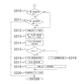
図11の説明に移り、確定図柄非表示期間である場合(図10のステップS302:「YES」)、主制御装置510は、第2特別図柄に関する保留記憶が存在するか否かを判断する(ステップS310)。第2特別図柄に関する保留記憶が存在しない場合(ステップS310:「NO」)、主制御装置510は、第1特別図柄に関する保留記憶が存在するか否かを判断する(ステップS311)。 Moving on to the explanation of FIG. 11, in the case of the confirmed symbol non-display period (step S302 of FIG. 10: “YES”), the main control device 510 determines whether or not there is a reserved memory related to the second special symbol (step S302 of FIG. 10: “YES”). Step S310). When the reserved memory related to the second special symbol does not exist (step S310: “NO”), the main controller 510 determines whether or not the reserved memory related to the first special symbol exists (step S311).

第1特別図柄または第2特別図柄に関する保留記憶が存在する場合(ステップS310:「YES」、ステップS311:「YES」)、主制御装置510は、第1特別図柄および第2特別図柄のうち処理の対象となる対象特別図柄に関する保留記憶から、最も古い保留記憶を読み出すとともに、対象特別図柄に関する保留記憶カウンタをデクリメントする(ステップS312)。その後、主制御装置510は、対象特別図柄に関する保留記憶カウンタの値を示す保留数指示コマンドをサブ統合制御装置520に送信する(ステップS313)。 When the reserved memory for the first special symbol or the second special symbol exists (step S310: "YES", step S311: "YES"), the main controller 510 processes the first special symbol and the second special symbol. The oldest reserved memory is read from the reserved memory related to the target special symbol, and the reserved storage counter related to the target special symbol is decremented (step S312). After that, the main control device 510 transmits a hold number instruction command indicating the value of the hold storage counter related to the target special symbol to the sub-integrated control device 520 (step S313).

その後、主制御装置510は、対象特別図柄に関する保留記憶として読み出した大当り決定用乱数と、大当り判断用判断テーブルとを比較する(ステップS314)。本実施形態では、大当り判断用判断テーブルは、大当り確率が低確率(例えば、1/358.1148)に設定された通常確率用テーブルと、大当り確率が高確率(例えば、1/37.6855)に設定された高確率用テーブルとを含む。主制御装置510は、通常遊技状態および時短遊技状態において通常確率用テーブルを使用し、確変時短遊技状態において高確率用テーブルを使用する。主制御装置510は、大当り決定用乱数と大当り判断用判断テーブルとの比較(ステップS314)に基づいて、対象特別図柄が大当りか否かを判断する(ステップS315)。 After that, the main control device 510 compares the big hit determination random number read out as the reserved memory for the target special symbol with the big hit determination determination table (step S314). In the present embodiment, the jackpot judgment judgment table includes a normal probability table in which the jackpot probability is set to a low probability (for example, 1 / 358.1148) and a jackpot probability is a high probability (for example, 1 / 37.68555). Includes a table for high probabilities set in. The main control device 510 uses the normal probability table in the normal game state and the time-saving game state, and uses the high-probability table in the probability variation time-short game state. The main control device 510 determines whether or not the target special symbol is a big hit based on the comparison between the big hit determination random number and the big hit determination determination table (step S314) (step S315).

対象特別図柄が大当りである場合(ステップS315:「YES」)、主制御装置510は、対象特別図柄に関する保留記憶として読み出した大当り図柄決定用乱数に基づいて大当り図柄を決定する(ステップS316)。その後、主制御装置510は、大当り遊技状態に関する各種条件(演出時間、演出パターンなど)を設定する(ステップS317)。その後、主制御装置510は、対象特別図柄に関する保留記憶として読み出した変動パターン決定用乱数に基づいて変動パターンを選択する(ステップS318)。その後、主制御装置510は、大当り図柄および変動パターンなどを示す変動指示コマンドをサブ統合制御装置520に送信する(ステップS320)。これによって、サブ統合制御装置520は、変動指示コマンドに基づいて、演出図柄表示装置230において表示される擬似演出を制御する。また、主制御装置510は、サブ統合制御装置520に対する変動指示コマンドの送信に合わせて、第1特図表示装置251または第2特図表示装置252に対して、変動表示を指示する制御信号を出力する。 When the target special symbol is a jackpot (step S315: “YES”), the main control device 510 determines the jackpot symbol based on the random number for determining the jackpot symbol read out as the hold memory for the target special symbol (step S316). After that, the main control device 510 sets various conditions (effect time, effect pattern, etc.) related to the jackpot game state (step S317). After that, the main control device 510 selects the variation pattern based on the variation pattern determination random number read out as the hold storage for the target special symbol (step S318). After that, the main control device 510 transmits a fluctuation instruction command indicating a jackpot symbol, a fluctuation pattern, and the like to the sub-integrated control device 520 (step S320). As a result, the sub-integrated control device 520 controls the pseudo effect displayed on the effect symbol display device 230 based on the variation instruction command. Further, the main control device 510 sends a control signal for instructing the fluctuation display to the first special figure display device 251 or the second special figure display device 252 in accordance with the transmission of the fluctuation instruction command to the sub-integrated control device 520. Output.

対象特別図柄がハズレである場合(ステップS315:「NO」)、主制御装置510は、対象特別図柄に関する保留記憶として読み出した乱数に基づいてハズレ図柄を決定する(ステップS319)。その後、主制御装置510は、対象特別図柄に関する保留記憶として読み出した乱数に基づいて変動パターンを選択する(ステップS318)。その後、主制御装置510は、ハズレ図柄および変動パターンなどを示す変動指示コマンドをサブ統合制御装置520に送信する(ステップS320)。これによって、サブ統合制御装置520は、変動指示コマンドに基づいて、演出図柄表示装置230において表示される擬似演出を制御する。また、主制御装置510は、サブ統合制御装置520に対する変動指示コマンドの送信に合わせて、第1特図表示装置251または第2特図表示装置252に対して、変動表示を指示する制御信号を出力する。 When the target special symbol is lost (step S315: “NO”), the main control device 510 determines the lost symbol based on the random number read as the hold memory for the target special symbol (step S319). After that, the main control device 510 selects the fluctuation pattern based on the random number read as the hold storage for the target special symbol (step S318). After that, the main control device 510 transmits a fluctuation instruction command indicating a loss symbol, a fluctuation pattern, and the like to the sub-integrated control device 520 (step S320). As a result, the sub-integrated control device 520 controls the pseudo effect displayed on the effect symbol display device 230 based on the variation instruction command. Further, the main control device 510 sends a control signal for instructing the fluctuation display to the first special figure display device 251 or the second special figure display device 252 in accordance with the transmission of the fluctuation instruction command to the sub-integrated control device 520. Output.

第1特別図柄および第2特別図柄に関する保留記憶が存在しない場合(ステップS310:「NO」、ステップS311:「NO」)、並びに、サブ統合制御装置520に変動指示コマンドを送信した後(ステップS320)、主制御装置510は、大当り遊技状態を制御する特別遊技処理に移行する。 When there is no reserved memory for the first special symbol and the second special symbol (step S310: "NO", step S311: "NO"), and after transmitting the variation instruction command to the sub-integrated control device 520 (step S320). ), The main control device 510 shifts to the special game process for controlling the jackpot game state.

図12の説明に移り、特図変動停止期間でない場合(図10のステップS301:「NO」)、言い換えると、第1特別図柄または第2特別図柄が変動中である場合、主制御装置510は、変動中の対象特別図柄に関する変動パターンに基づいて設定された変動時間が経過したか否かを判断する(ステップS330)。変動時間が経過していない場合(ステップS330:「NO」)、主制御装置510は、大当り遊技状態を制御する特別遊技処理に移行する。変動時間が経過した場合(ステップS330:「YES」)、主制御装置510は、大当り図柄またはハズレ図柄を確定表示させる制御信号を第1特図表示装置251または第2特図表示装置252に出力するとともに、大当り図柄またはハズレ図柄を確定表示させる図柄停止コマンドをサブ統合制御装置520に送信する(ステップS331)。 Moving on to the explanation of FIG. 12, when it is not the special figure fluctuation stop period (step S301 of FIG. 10: “NO”), in other words, when the first special symbol or the second special symbol is changing, the main control device 510 , It is determined whether or not the fluctuation time set based on the fluctuation pattern of the target special symbol being changed has elapsed (step S330). When the fluctuation time has not elapsed (step S330: “NO”), the main control device 510 shifts to the special game process for controlling the jackpot game state. When the fluctuation time has elapsed (step S330: “YES”), the main control device 510 outputs a control signal for confirming and displaying the jackpot symbol or the lost symbol to the first special symbol display device 251 or the second special symbol display device 252. At the same time, a symbol stop command for confirming and displaying the jackpot symbol or the lost symbol is transmitted to the sub-integrated control device 520 (step S331).

大当り図柄を確定表示する場合(ステップS332:「YES」)、主制御装置510は、大当り図柄を確定表示させる時間を設定するとともに(ステップS333)、大当りフラグを有効な値にセットすることによって条件装置を作動させる(ステップS334)。その後、主制御装置510は、確変フラグおよび時短フラグを無効な値にリセットするとともに、確変カウンタおよび時短カウンタを無効な値にリセットする(ステップS335)。確変フラグは、通常遊技状態より高い当選確率で第1特別図柄および第2特別図柄の当否判断を実施するか否かを設定するフラグである。時短フラグは、時短遊技状態を実施するか否かを設定するフラグである。確変カウンタは、通常遊技状態より高い当選確率で第1特別図柄および第2特別図柄の当否判断を実施する回数を設定するカウンタである。時短カウンタは、時短遊技状態を実施する回数を設定するカウンタである。各種カウンタをリセットした後(ステップS335)、主制御装置510は、図柄確定表示後の遊技状態を示す状態指定コマンドをサブ統合制御装置520および枠制御装置560に送信した上で、大当り遊技状態を制御する特別遊技処理に移行する。 When the jackpot symbol is confirmed and displayed (step S332: "YES"), the main control device 510 sets the time for the jackpot symbol to be confirmed and displayed (step S333), and sets the jackpot flag to a valid value. The device is activated (step S334). After that, the main control device 510 resets the probability variation flag and the time reduction flag to invalid values, and resets the probability variation counter and the time reduction counter to invalid values (step S335). The probability variation flag is a flag that sets whether or not to determine whether or not the first special symbol and the second special symbol are successful or not with a winning probability higher than that in the normal gaming state. The time saving flag is a flag for setting whether or not to carry out the time saving game state. The probability variation counter is a counter that sets the number of times that the winning / failing determination of the first special symbol and the second special symbol is performed with a winning probability higher than that in the normal gaming state. The time saving counter is a counter that sets the number of times the time saving game state is executed. After resetting the various counters (step S335), the main control device 510 sends a state designation command indicating the game state after the symbol confirmation display to the sub-integrated control device 520 and the frame control device 560, and then sets the jackpot game state. Shift to the special game processing to be controlled.

ハズレ図柄を確定表示させる場合(ステップS332:「NO」)、主制御装置510は、ハズレ図柄を確定表示させる時間を設定する(ステップS337)。その後、主制御装置510は、確変フラグが有効な値「1」である場合(ステップS338:「YES」)、確変カウンタをデクリメントする(ステップS339)。その後、主制御装置510は、確変カウンタが「0」である場合(ステップS340:「YES」)、確変フラグを無効な値「0」にセットする(ステップS341)。 When the lost symbol is confirmed and displayed (step S332: “NO”), the main control device 510 sets the time for confirming and displaying the lost symbol (step S337). After that, when the probability variation flag is a valid value "1" (step S338: "YES"), the main control device 510 decrements the probability variation counter (step S339). After that, when the probability change counter is "0" (step S340: "YES"), the main control device 510 sets the probability change flag to an invalid value "0" (step S341).

確変フラグおよび確変カウンタに関する処理を終えた後(ステップS338:「NO」、ステップS340:「NO」、ステップS341)、主制御装置510は、時短フラグが有効な値「1」である場合(ステップS342:「YES」)、時短カウンタをデクリメントする(ステップS343)。その後、主制御装置510は、時短カウンタが「0」である場合(ステップS344:「YES」)、時短フラグを無効な値「0」にセットする(ステップS345)。時短フラグおよび時短カウンタに関する処理を終えた後(ステップS342:「NO」、ステップS344:「NO」、ステップS345)、主制御装置510は、図柄確定表示後の遊技状態を示す状態指定コマンドをサブ統合制御装置520および枠制御装置560に送信した上で、大当り遊技状態を制御する特別遊技処理に移行する。 After finishing the processing related to the probability change flag and the probability change counter (step S338: "NO", step S340: "NO", step S341), the main controller 510 determines that the time saving flag is a valid value "1" (step). S342: “YES”), the time reduction counter is decremented (step S343). After that, when the time saving counter is "0" (step S344: "YES"), the main control device 510 sets the time saving flag to an invalid value "0" (step S345). After finishing the processing related to the time saving flag and the time saving counter (step S342: "NO", step S344: "NO", step S345), the main control device 510 subsubscribes the state designation command indicating the game state after the symbol confirmation display. After transmitting to the integrated control device 520 and the frame control device 560, the process shifts to the special game process for controlling the jackpot game state.

図13の説明に移り、第1特別図柄および第2特別図柄の確定図柄を非表示とする確定図柄非表示期間でない場合(図10のステップS302:「NO」)、言い換えると、第1特別図柄または第2特別図柄を確定表示している場合、主制御装置510は、確定表示されている対象特別図柄に関する変動パターンに基づいて設定された確定表示時間が経過したか否かを判断する(ステップS350)。確定表示時間が経過していない場合(ステップS350:「NO」)、主制御装置510は、大当り遊技状態を制御する特別遊技処理に移行する。確定表示時間が経過した場合(ステップS350:「YES」)、主制御装置510は、確定表示を終了させる制御信号を第1特図表示装置251または第2特図表示装置252に出力するとともに、演出図柄による確定表示を終了させるコマンドをサブ統合制御装置520に送信する(ステップS351)。その後、主制御装置510は、大当り遊技状態を制御する特別遊技処理に移行する。 Moving on to the explanation of FIG. 13, when it is not the fixed symbol non-display period in which the fixed symbols of the first special symbol and the second special symbol are hidden (step S302: “NO” in FIG. 10), in other words, the first special symbol Alternatively, when the second special symbol is fixedly displayed, the main control unit 510 determines whether or not the fixed display time set based on the fluctuation pattern of the target special symbol that is fixedly displayed has elapsed (step). S350). When the confirmed display time has not elapsed (step S350: “NO”), the main control device 510 shifts to the special game process for controlling the jackpot game state. When the confirmation display time has elapsed (step S350: “YES”), the main control device 510 outputs a control signal for ending the confirmation display to the first special figure display device 251 or the second special figure display device 252, and also outputs the control signal. A command for ending the confirmation display by the effect symbol is transmitted to the sub-integrated control device 520 (step S351). After that, the main control device 510 shifts to the special game process for controlling the jackpot game state.

〔特別遊技処理〕
図14、図15および図16は、主制御装置510が実行する「特別遊技処理」を示すフローチャートである。この「特別遊技処理」は、大当り遊技状態を制御するサブルーチンである。図14に示すように、「特別遊技処理」を開始した後、主制御装置510は、大当りフラグに基づいて、条件装置が作動しているか否かを判断する(ステップS400)。条件装置が作動していない場合(ステップS400:「NO」)、主制御装置510は、メインルーチンにリターンする。
[Special game processing]
14, 15 and 16 are flowcharts showing "special game processing" executed by the main control device 510. This "special game processing" is a subroutine that controls the jackpot game state. As shown in FIG. 14, after starting the "special game process", the main control device 510 determines whether or not the condition device is operating based on the jackpot flag (step S400). If the condition device is not operating (step S400: “NO”), the main controller 510 returns to the main routine.

条件装置が作動している場合(ステップS400:「YES」)、主制御装置510は、大入賞口248が閉鎖中であるか否かを判断する(ステップS401)。大入賞口248が閉鎖中である場合(ステップS401:「YES」)、主制御装置510は、大当り遊技状態に先立つ大当り開始演出を実施中であるか否かを判断する(ステップS402)。大当り開始演出を実施中である場合(ステップS402:「YES」)、主制御装置510は、大当り開始演出を終了する時間であるか否かを判断する(ステップS403)。大当り開始演出を終了する時間である場合(ステップS403:「YES」)、主制御装置510は、大入賞口248を開放する大入賞口開放処理(ステップS404)を実行する。大当り開始演出を終了する時間でない場合(ステップS403:「NO」)、並びに、大入賞口開放処理(ステップS404)を実行した後、主制御装置510は、メインルーチンにリターンする。 When the condition device is operating (step S400: “YES”), the main control device 510 determines whether or not the grand prize opening 248 is closed (step S401). When the big winning opening 248 is closed (step S401: “YES”), the main control device 510 determines whether or not the big hit start effect prior to the big hit game state is being executed (step S402). When the jackpot start effect is being implemented (step S402: “YES”), the main control device 510 determines whether or not it is time to end the jackpot start effect (step S403). When it is time to end the jackpot start effect (step S403: “YES”), the main control device 510 executes the jackpot opening process (step S404) for opening the jackpot 248. When it is not the time to end the jackpot start effect (step S403: “NO”), and after executing the jackpot opening process (step S404), the main control device 510 returns to the main routine.

大当り開始演出を実施中でない場合(ステップS402:「NO」)、主制御装置510は、前回の開放期間から次回の開放期間までの間に大入賞口248を一時的に閉鎖する期間であるインターバル中であるか否かを判断する(ステップS405)。インターバル中である場合(ステップS405:「YES」)、主制御装置510は、インターバルを終了する時間であるか否かを判断する(ステップS406)。インターバルを終了する時間である場合(ステップS406:「YES」)、主制御装置510は、大入賞口248を開放する大入賞口開放処理(ステップS408)を実行する。インターバルを終了する時間でない場合(ステップS406:「NO」)、並びに、大入賞口開放処理(ステップS408)を実行した後、主制御装置510は、メインルーチンにリターンする。 When the jackpot start effect is not being performed (step S402: “NO”), the main control device 510 is an interval during which the jackpot 248 is temporarily closed between the previous opening period and the next opening period. It is determined whether or not it is inside (step S405). If the interval is in progress (step S405: “YES”), the main controller 510 determines whether or not it is time to end the interval (step S406). When it is time to end the interval (step S406: “YES”), the main control device 510 executes the large winning opening opening process (step S408) for opening the large winning opening 248. When it is not the time to end the interval (step S406: “NO”), and after executing the large winning opening opening process (step S408), the main control device 510 returns to the main routine.

インターバル中でない場合(ステップS405:「NO」)、主制御装置510は、大当り終了演出中であるか否かを判断する(ステップS411)。大当り終了演出中でない場合(ステップS411:「YES」)、主制御装置510は、大当り開始演出を指示するコマンドをサブ統合制御装置520に送信する大当り開始演出処理(ステップS412)を実行する。大当り終了演出中である場合(ステップS411:「NO」)、並びに、大当り開始演出処理(ステップS412)を実行した後、主制御装置510は、メインルーチンにリターンする。 If it is not in the interval (step S405: “NO”), the main control device 510 determines whether or not the jackpot end effect is in progress (step S411). When the jackpot end effect is not in progress (step S411: “YES”), the main control device 510 executes the jackpot start effect process (step S412) in which a command instructing the jackpot start effect is transmitted to the sub-integrated control device 520. When the jackpot end effect is in progress (step S411: "NO"), and after executing the jackpot start effect process (step S412), the main control device 510 returns to the main routine.

図15の説明に移り、大入賞口248が閉鎖中でない場合(図14のステップS401:「NO」)、言い換えると、大入賞口248が開放されている場合、主制御装置510は、開放中の大入賞口248への入賞数が規定数(例えば、9個)未満であるか否かを判断する(ステップS430)。開放中の大入賞口248への入賞数が規定数未満である場合(ステップS430:「YES」)、主制御装置510は、大入賞口248を開放する開放時間が経過しているか否かを判断する(ステップS431)。大入賞口248を開放する開放時間が経過していない場合(ステップS431:「NO」)、主制御装置510は、メインルーチンにリターンする。 Moving on to the explanation of FIG. 15, when the large winning opening 248 is not closed (step S401 of FIG. 14: “NO”), in other words, when the large winning opening 248 is open, the main control device 510 is open. It is determined whether or not the number of winnings in the large winning opening 248 is less than the specified number (for example, 9) (step S430). When the number of winnings to the large winning opening 248 being opened is less than the specified number (step S430: “YES”), the main controller 510 determines whether or not the opening time for opening the large winning opening 248 has elapsed. Determine (step S431). If the opening time for opening the grand prize opening 248 has not elapsed (step S431: “NO”), the main control device 510 returns to the main routine.

開放中の大入賞口248への入賞数が規定数を超える場合(ステップS430:「NO」)、または、大入賞口248を開放する開放時間が経過している場合(ステップS431:「YES」)、主制御装置510は、大入賞口248を閉鎖する大入賞口閉鎖処理(ステップS432)を実行する。その後、主制御装置510は、先の大入賞口閉鎖処理(ステップS432)において終了した大当り遊技のラウンドが最終ラウンド(例えば、13ラウンド目)であるか否かを判断する(ステップS433)。最終ラウンドでない場合(ステップS433:「NO」)、主制御装置510は、前回の開放期間から次回の開放期間までの間に大入賞口248を一時的に閉鎖するインターバルを実行する(ステップS438)。その後、主制御装置510は、メインルーチンにリターンする。 When the number of winnings to the large winning opening 248 being opened exceeds the specified number (step S430: "NO"), or when the opening time for opening the large winning opening 248 has elapsed (step S431: "YES"). ), The main control device 510 executes the large winning opening closing process (step S432) for closing the large winning opening 248. After that, the main control device 510 determines whether or not the round of the jackpot game completed in the previous jackpot closing process (step S432) is the final round (for example, the 13th round) (step S433). If it is not the final round (step S433: “NO”), the main controller 510 executes an interval for temporarily closing the grand prize opening 248 between the previous opening period and the next opening period (step S438). .. After that, the main controller 510 returns to the main routine.

先の大入賞口閉鎖処理(ステップS432)において終了した大当り遊技のラウンドが最終ラウンドである場合(ステップS433:「YES」)、主制御装置510は、大当り遊技状態の終了を示す大当り終了演出を指示するコマンドをサブ統合制御装置520に送信する(ステップS436)。その後、主制御装置510は、条件装置を停止する条件装置停止処理(ステップS437)を実行する。 When the round of the jackpot game completed in the previous jackpot closing process (step S432) is the final round (step S433: “YES”), the main control device 510 produces a jackpot end effect indicating the end of the jackpot game state. The command to be instructed is transmitted to the sub-integrated control device 520 (step S436). After that, the main control device 510 executes the condition device stop process (step S437) for stopping the condition device.

図16の説明に移り、条件装置停止処理(図15のステップS437)を実行した後、主制御装置510は、特典フラグが有効な値「1」であるか否かを判断する(ステップS440)。本実施形態では、主制御装置510は、大当り図柄の種類に応じて、特典フラグを有効な値「1」にセットする。他の実施形態では、大当り遊技の最終ラウンドにおいて、大入賞口248の内部に設けられた確変口(図示しない)に遊技球が入球した場合、主制御装置510は、特典フラグを有効な値「1」にセットしてもよい。 Moving on to the description of FIG. 16, after executing the conditional device stop process (step S437 in FIG. 15), the main control device 510 determines whether or not the privilege flag is a valid value “1” (step S440). .. In the present embodiment, the main control device 510 sets the privilege flag to a valid value "1" according to the type of the jackpot symbol. In another embodiment, in the final round of the jackpot game, when the game ball enters the probability change opening (not shown) provided inside the big winning opening 248, the main control device 510 sets the privilege flag to a valid value. It may be set to "1".

特典フラグが有効な値「1」である場合(ステップS440:「YES」)、主制御装置510は、確変フラグを有効な値「1」にセットするとともに(ステップS441)、確変カウンタに値「160」をセットする(ステップS442)。その後、主制御装置510は、時短フラグを有効な値「1」にセットするとともに(ステップS443)、時短カウンタに値「160」をセットする(ステップS444)。 When the privilege flag is a valid value "1" (step S440: "YES"), the main controller 510 sets the probability variation flag to a valid value "1" (step S441) and sets the probability variation counter to the value "1". 160 ”is set (step S442). After that, the main control device 510 sets the time saving flag to a valid value "1" (step S443) and sets the time saving counter to the value "160" (step S444).

特典フラグが有効な値「1」でない場合(ステップS440:「NO」)、言い換えると、特典フラグが無効な値「0」である場合、主制御装置510は、確変フラグを無効な値「0」にセットするとともに(ステップS451)、確変カウンタに値「0」をセットする(ステップS452)。その後、主制御装置510は、時短フラグを無効な値「0」にセットするとともに(ステップS453)、時短カウンタに値「0」をセットする(ステップS454)。 If the privilege flag is not a valid value "1" (step S440: "NO"), in other words, if the privilege flag is an invalid value "0", the main controller 510 sets the probability variation flag to an invalid value "0". (Step S451), and the value "0" is set in the probability variation counter (step S452). After that, the main control device 510 sets the time saving flag to an invalid value "0" (step S453) and sets the time saving counter to the value "0" (step S454).

時短カウンタをセットした後(ステップS444,S454)、主制御装置510は、特典フラグを無効な値「0」にリセットする(ステップS445)。その後、主制御装置510は、確変フラグおよび時短フラグに基づいて設定される大当り遊技後の遊技状態の報知を指示するコマンドをサブ統合制御装置520に送信する(ステップS446)。その後、主制御装置510は、確変フラグおよび時短フラグに基づいて設定される大当り遊技後の遊技状態を指示するコマンドをサブ統合制御装置520および枠制御装置560に送信する(ステップS447)。その後、主制御装置510は、メインルーチンにリターンする。 After setting the time reduction counter (steps S444 and S454), the main controller 510 resets the privilege flag to an invalid value "0" (step S445). After that, the main control device 510 transmits a command for instructing the notification of the game state after the big hit game, which is set based on the probability change flag and the time reduction flag, to the sub-integrated control device 520 (step S446). After that, the main control device 510 transmits a command indicating the game state after the big hit game, which is set based on the probability change flag and the time reduction flag, to the sub-integrated control device 520 and the frame control device 560 (step S447). After that, the main controller 510 returns to the main routine.

〔入賞確認処理〕
図17は、主制御装置510が実行する「入賞確認処理」を示すフローチャートである。この「入賞確認処理」は、図8の入賞確認処理(ステップS107)に含まれるサブルーチンである。入賞確認処理を開始した後、主制御装置510は、入賞を検出したか否かを判断する(ステップS512)。主制御装置510は、第1始動口スイッチ271、第2始動口スイッチ272、左入賞口スイッチ274およびカウントスイッチ276からの検知信号に基づいて、入賞を検出したか否かを判断する。
[Prize confirmation process]
FIG. 17 is a flowchart showing a “winning confirmation process” executed by the main control device 510. This "winning confirmation process" is a subroutine included in the winning confirmation process (step S107) of FIG. After starting the winning confirmation process, the main control device 510 determines whether or not the winning has been detected (step S512). The main control device 510 determines whether or not the winning is detected based on the detection signals from the first starting port switch 271, the second starting port switch 272, the left winning port switch 274, and the count switch 276.

入賞を検知した場合(ステップS512:「YES」)、主制御装置510は、遊技者の持ち球に加算すべき賞球数を判断する(ステップS514)。主制御装置510は、普通入賞口246への入賞を検知する左入賞口スイッチ274からの検知信号である場合、賞球数が10個であると判断する。主制御装置510は、第1始動口241への入賞を検知する第1始動口スイッチ271からの検知信号である場合、並びに、第2始動口242への入賞を検知する第2始動口スイッチ272からの検知信号である場合、賞球数が3個であると判断する。主制御装置510は、大入賞口248への入賞を検知するカウントスイッチ276からの検知信号である場合、賞球数が13個であると判断する。各入賞口に応じた賞球数は、適宜設定可能である。 When the winning is detected (step S512: “YES”), the main control device 510 determines the number of prize balls to be added to the player's balls (step S514). The main control device 510 determines that the number of winning balls is 10 when the detection signal is from the left winning opening switch 274 that detects the winning of the normal winning opening 246. The main control device 510 is a detection signal from the first start port switch 271 that detects the winning of the first starting port 241 and the second starting port switch 272 that detects the winning of the second starting port 242. If it is a detection signal from, it is determined that the number of prize balls is three. The main control device 510 determines that the number of prize balls is 13 when the detection signal is from the count switch 276 that detects the winning of the large winning opening 248. The number of prize balls according to each winning opening can be set as appropriate.

賞球数を判断した後(ステップS514)、並びに、入賞を検知しない場合(ステップS512:「NO」)、主制御装置510は、賞球数表示装置286に賞球数の表示を指示する(ステップS516)。これによって、賞球数表示装置286には、各入賞口に応じて賞球数が表示される。入賞を検知しない場合、賞球数表示装置286には、入賞がないことを示す数字「0」が表示される。賞球数の表示を指示した後(ステップS516)、主制御装置510は、図17の入賞確認処理を終え、メインルーチンにリターンする。 After determining the number of prize balls (step S514) and when the winning is not detected (step S512: "NO"), the main control device 510 instructs the prize ball number display device 286 to display the number of prize balls (step S512: "NO"). Step S516). As a result, the number of prize balls is displayed on the prize ball number display device 286 according to each winning opening. If the winning is not detected, the number "0" indicating that there is no winning is displayed on the prize ball number display device 286. After instructing the display of the number of prize balls (step S516), the main control device 510 finishes the winning confirmation process of FIG. 17 and returns to the main routine.

〔各出力処理〕
図18は、主制御装置510が実行する「各出力処理」を示すフローチャートである。この「各出力処理」は、図8の各出力処理(ステップS109)に相当するサブルーチンである。各出力処理において、主制御装置510は、図17の入賞確認処理に基づく賞球数を示す賞球情報を、主制御装置510からの片方向通信によって枠制御装置560に送信する(ステップS522)。その後、主制御装置510は、図17の入賞確認処理に基づく賞球数を示す賞球情報を、主制御装置510からの片方向通信によって主制御装置510に送信する(ステップS524)。各出力処理において、主制御装置510は、賞球情報のほか、各種の情報を枠制御装置560および主制御装置510に出力する。各種の情報を出力した後、主制御装置510は、図18の各出力処理を終了し、メインルーチンにリターンする。
[Each output processing]
FIG. 18 is a flowchart showing "each output process" executed by the main control device 510. This "each output process" is a subroutine corresponding to each output process (step S109) of FIG. In each output process, the main control device 510 transmits prize ball information indicating the number of prize balls based on the prize confirmation process of FIG. 17 to the frame control device 560 by one-way communication from the main control device 510 (step S522). .. After that, the main control device 510 transmits the prize ball information indicating the number of prize balls based on the winning confirmation process of FIG. 17 to the main control device 510 by one-way communication from the main control device 510 (step S524). In each output process, the main control device 510 outputs various information in addition to the prize ball information to the frame control device 560 and the main control device 510. After outputting various kinds of information, the main control device 510 ends each output process of FIG. 18 and returns to the main routine.

主制御装置510は、パチンコ機10における遊技状態を示す遊技状態情報として次の情報を、枠制御装置560からカードユニット80を介してホールコンピュータ90に送信する。<情報の名称:情報の内容>
情報A1:大当り
情報A2〜A8:予備
情報A9:大当り中および時短中
情報A10:確変中
情報A11:時短中
情報A12:図柄変動中
情報A13:電波センサによる不正行為の検知(エラー)
情報A14:磁石センサによる不正行為の検知(エラー)
情報A15:不正入賞の検知(エラー)
The main control device 510 transmits the following information from the frame control device 560 to the hall computer 90 via the card unit 80 as game state information indicating the game state in the pachinko machine 10. <Name of information: Content of information>
Information A1: Big hit information A2 to A8: Preliminary information A9: Big hit and time saving information A10: Probability change information A11: Time saving information A12: Design change information A13: Fraud detection by radio wave sensor (error)
Information A14: Detection of fraudulent activity by magnet sensor (error)
Information A15: Unauthorized winning detection (error)

主制御装置510は、パチンコ機10における遊技状態を示す遊技状態情報として次の情報を、枠制御装置560に送信する。これらの情報は、ホールコンピュータ90には送信されない。<情報の名称:情報の内容>
情報B1:大当り遊技の開始
情報B2:大当り遊技におけるラウンド間のインターバル
情報B3:大当り遊技の終了
情報B4:大当り遊技のラウンド数
情報B5:図柄の変動パターン
情報B6〜B10:予備
情報B11:確変あり(時短あり)
情報B12:確変あり(時短なし)
情報B13:確変なし(時短あり)
情報B14:確変なし(時短なし)
情報B15:待機モード(省電力モード)の開始
情報B16:待機モードの終了
情報B17:大入賞口への入賞カウント数
情報B18:普通電動役物への入賞カウント数
情報B19:第1保留記憶の保留数
情報B20:第2保留記憶の保留数
情報B21:普図保留記憶の保留数
情報B22:一般入賞口への入賞
The main control device 510 transmits the following information to the frame control device 560 as game state information indicating the game state in the pachinko machine 10. This information is not transmitted to the hall computer 90. <Name of information: Content of information>
Information B1: Start of big hit game Information B2: Interval between rounds in big hit game Information B3: End of big hit game Information B4: Number of rounds of big hit game Information B5: Pattern fluctuation pattern Information B6 to B10: Preliminary information B11: Probability change (There is a time saving)
Information B12: Probability change (no time reduction)
Information B13: No change (with time reduction)
Information B14: No probability change (no time reduction)
Information B15: Start of standby mode (power saving mode) Information B16: End of standby mode Information B17: Number of winning counts to the large winning opening Information B18: Number of winning counts to ordinary electric accessories Information B19: First hold memory Number of Holds Information B20: Number of Holds of Second Hold Memory Information B21: Number of Holds of General Figure Hold Memory Information B22: Winning to General Winner

情報B15の待機モードの開始に関し、主制御装置510は、普通図柄、第1特別図柄および第2特別図柄の各保留記憶がない状態において、全ての図柄の変動が終了してから所定時間が経過した場合、待機モードを開始する。情報B16の待機モードの終了に関し、主制御装置510は、待機モードを実行中に、普通図柄、第1特別図柄および第2特別図柄のいずれかの保留記憶が記憶された場合、待機モードを終了する。 Regarding the start of the standby mode of the information B15, the main control device 510 elapses a predetermined time from the end of the fluctuation of all the symbols in the state where there is no hold storage of the normal symbol, the first special symbol, and the second special symbol. If so, the standby mode is started. Regarding the termination of the standby mode of the information B16, the main control device 510 terminates the standby mode when any of the hold memory of the normal symbol, the first special symbol, and the second special symbol is stored during the standby mode. To do.

〔持ち球管理処理〕
図19は、枠制御装置560が実行する「持ち球管理処理」を示すフローチャートである。この「持ち球管理処理」は、持ち球の数である持ち球数を管理する処理である。枠制御装置560は、持ち球管理処理を所定のタイミングで繰り返し実行する。持ち球管理処理を開始した後、枠制御装置560は、カードユニット80から貸し出し情報を受信したか否かを判断する(ステップS612)。カードユニット80からの貸し出し情報は、遊技者から受け取った紙幣、または、記録媒体である記録カードから読み取った情報に基づいて、遊技者に貸し出す遊技球の数を示す。貸し出し情報を受信した場合(ステップS612:「YES」)、枠制御装置560は、貸し出し情報に基づく遊技球の数を、枠制御装置560において管理する持ち球数に加算する(ステップS614)。
[Holding ball management process]
FIG. 19 is a flowchart showing a “ball holding management process” executed by the frame control device 560. This "holding ball management process" is a process of managing the number of holding balls, which is the number of holding balls. The frame control device 560 repeatedly executes the holding ball management process at a predetermined timing. After starting the ball holding management process, the frame control device 560 determines whether or not the rental information has been received from the card unit 80 (step S612). The lending information from the card unit 80 indicates the number of game balls to be lent to the player based on the banknotes received from the player or the information read from the recording card which is the recording medium. When the rental information is received (step S612: “YES”), the frame control device 560 adds the number of game balls based on the rental information to the number of balls held in the frame control device 560 (step S614).

貸し出し情報に基づいて持ち球数を加算した後(ステップS614)、並びに、貸し出し情報を受信していない場合(ステップS612:「NO」)、枠制御装置560は、発射装置310から遊技領域210へと発射される遊技球である発射球を検出したか否かを判断する(ステップS622)。枠制御装置560は、発射入口センサ315による検知信号に基づいて発射球の検出を判断する。発射球を検出した場合(ステップS622:「YES」)、枠制御装置560は、発射球の数を、枠制御装置560において管理する持ち球数から減算する(ステップS624)。 After adding the number of balls held based on the rental information (step S614) and when the rental information is not received (step S612: “NO”), the frame control device 560 moves from the launching device 310 to the game area 210. It is determined whether or not the launch ball, which is the game ball to be launched, is detected (step S622). The frame control device 560 determines the detection of the launch ball based on the detection signal from the launch inlet sensor 315. When the launch ball is detected (step S622: “YES”), the frame control device 560 subtracts the number of launch balls from the number of balls held in the frame control device 560 (step S624).

発射球に基づいて持ち球数を減算した後(ステップS624)、並びに、発射球を検出していない場合(ステップS622:「NO」)、枠制御装置560は、賞球数を示す賞球情報を主制御装置510から受信したか否かを判断する(ステップS632)。賞球情報を受信した場合(ステップS632:「YES」)、枠制御装置560は、賞球情報に基づく賞球数を、枠制御装置560において管理する持ち球数に加算する(ステップS634)。 After subtracting the number of balls held based on the number of launch balls (step S624), and when the number of launch balls is not detected (step S622: "NO"), the frame control device 560 indicates the prize ball information indicating the number of prize balls. Is determined from the main control device 510 (step S632). When the prize ball information is received (step S632: “YES”), the frame control device 560 adds the number of prize balls based on the prize ball information to the number of balls held in the frame control device 560 (step S634).

賞球情報に基づいて持ち球数を加算した後(ステップS634)、並びに、賞球情報を受信していない場合(ステップS632:「NO」)、枠制御装置560は、枠制御装置560において管理する持ち球数の表示を持ち球数表示装置164に指示する(ステップS642)。その後、枠制御装置560は、図19の持ち球管理処理を終了する。 After adding the number of balls held based on the prize ball information (step S634) and when the prize ball information is not received (step S632: "NO"), the frame control device 560 is managed by the frame control device 560. Instruct the holding ball number display device 164 to display the number of balls held (step S642). After that, the frame control device 560 ends the ball holding management process shown in FIG.

〔情報出力処理〕
図20は、枠制御装置560が実行する「情報出力処理」を示すフローチャートである。この「情報出力処理」は、各種の情報をサブ統合制御装置520に出力する処理である。枠制御装置560は、情報出力処理を所定のタイミングで繰り返し実行する。情報出力処理において、枠制御装置560は、図19の持ち球管理処理に基づく持ち球数を示す持ち球情報を、枠制御装置560からの片方向通信によってサブ統合制御装置520に送信する(ステップS644)。情報出力処理において、枠制御装置560は、持ち球情報のほか、次の情報を、枠制御装置560からの片方向通信によってサブ統合制御装置520に送信する。
情報C1:入賞球の検出情報
情報C2:アウト球の検出情報
情報C3:枠側エラー情報
情報C4:夜間監視情報
情報C5:カード報知情報
[Information output processing]
FIG. 20 is a flowchart showing an “information output process” executed by the frame control device 560. This "information output process" is a process of outputting various types of information to the sub-integrated control device 520. The frame control device 560 repeatedly executes the information output process at a predetermined timing. In the information output process, the frame control device 560 transmits the ball holding information indicating the number of balls held based on the ball holding management process of FIG. 19 to the sub-integrated control device 520 by one-way communication from the frame control device 560 (step). S644). In the information output process, the frame control device 560 transmits the following information in addition to the holding ball information to the sub-integrated control device 520 by one-way communication from the frame control device 560.
Information C1: Winning ball detection information Information C2: Out ball detection information Information C3: Frame side error information Information C4: Night monitoring information Information C5: Card notification information

入賞球の検出情報(情報C1)は、入賞球センサ344からの検知信号に基づく入賞球の数を示す情報である。アウト球の検出情報(情報C2)は、アウト球センサ345からの検知信号に基づくアウト球の数を示す情報である。枠側エラー情報(情報C3)は、枠制御装置560によって管理される発射装置310、研磨装置320および揚上装置330などの機器における異常を示す情報である。夜間監視情報(情報C4)は、夜間監視装置352からの検知信号に基づく異常を示す情報である。カード報知情報(情報C5)は、カードユニット80において記録カードを返却する旨を示す情報である。サブ統合制御装置520は、計数スイッチ162に操作入力を受け付けた場合、大当り遊技終了後の次の遊技状態を開始するまでのインターバル期間、並びに、返却ボタン813に操作入力を受け付けた場合、カード報知情報(情報C5)をサブ統合制御装置520に送信する。 The winning ball detection information (information C1) is information indicating the number of winning balls based on the detection signal from the winning ball sensor 344. The out-ball detection information (information C2) is information indicating the number of out-balls based on the detection signal from the out-ball sensor 345. The frame side error information (information C3) is information indicating an abnormality in equipment such as a launching device 310, a polishing device 320, and a lifting device 330 managed by the frame control device 560. The nighttime monitoring information (information C4) is information indicating an abnormality based on a detection signal from the nighttime monitoring device 352. The card notification information (information C5) is information indicating that the recording card will be returned in the card unit 80. When the sub-integrated control device 520 receives the operation input to the counting switch 162, the interval period until the start of the next game state after the end of the big hit game, and when the operation input is received to the return button 813, the sub-integrated control device 520 notifies the card. Information (information C5) is transmitted to the sub-integrated control device 520.

〔持ち球表示処理〕
図21は、サブ統合制御装置520が実行する「持ち球表示処理」を示すフローチャートである。この「持ち球表示処理」は、演出図柄表示装置230に持ち球数を表示する処理である。サブ統合制御装置520は、持ち球表示処理を所定のタイミングで繰り返し実行する。持ち球表示処理を開始した後、サブ統合制御装置520は、図19の持ち球管理処理に基づく持ち球数を示す持ち球情報を、枠制御装置560からの片方向通信によって枠制御装置560から受信する(ステップS712)。その後、サブ統合制御装置520は、枠制御装置560からの持ち球情報に基づく持ち球数の表示を、演出図柄制御装置530を介して演出図柄表示装置230に指示する(ステップS714)。その後、サブ統合制御装置520は、持ち球表示処理を終了する。サブ統合制御装置520は、枠制御装置560において管理されている持ち球数が所定個数単位(例えば、10個)で変化する毎に、持ち球数を示す持ち球情報を枠制御装置560から受信してもよいし、枠制御装置560において管理されている持ち球数が変化する毎に、持ち球数を示す持ち球情報を枠制御装置560から受信してもよい。サブ統合制御装置520は、枠制御装置560から送信される持ち球情報とは異なる情報に基づいて持ち球数を算出し、その算出した持ち球数の表示を演出図柄制御装置530を介して演出図柄表示装置230に指示してもよい。
[Holding ball display processing]
FIG. 21 is a flowchart showing a “ball holding display process” executed by the sub-integrated control device 520. This "holding ball display process" is a process of displaying the number of held balls on the effect symbol display device 230. The sub-integrated control device 520 repeatedly executes the holding ball display process at a predetermined timing. After starting the holding ball display process, the sub-integrated control device 520 transmits the holding ball information indicating the number of holding balls based on the holding ball management process of FIG. 19 from the frame control device 560 by one-way communication from the frame control device 560. Receive (step S712). After that, the sub-integrated control device 520 instructs the effect symbol display device 230 to display the number of balls held based on the ball possession information from the frame control device 560 (step S714). After that, the sub-integrated control device 520 ends the holding ball display process. The sub-integrated control device 520 receives the ball holding information indicating the number of balls held from the frame control device 560 each time the number of balls held in the frame control device 560 changes in a predetermined number unit (for example, 10). Alternatively, each time the number of balls held in the frame control device 560 changes, information on the number of balls held may be received from the frame control device 560. The sub-integrated control device 520 calculates the number of balls held based on information different from the ball holding information transmitted from the frame control device 560, and displays the calculated number of balls held via the effect symbol control device 530. You may instruct the symbol display device 230.

図22は、演出図柄表示装置230における表示の一例を示す画面401を示す説明図である。画面401は、演出図柄表示領域411,412,413と、表示領域422と、表示領域424とを備える。演出図柄表示領域411は、左側に位置する演出図柄の可変表示および確定表示を実施する領域である。演出図柄表示領域412は、中央に位置する演出図柄の可変表示および確定表示を実施する領域である。演出図柄表示領域413は、右側に位置する演出図柄の可変表示および確定表示を実施する領域である。表示領域422は、主制御装置510からの賞球情報に基づく賞球数を表示する領域である。表示領域424は、枠制御装置560からの持ち球情報に基づく持ち球数を表示する領域である。 FIG. 22 is an explanatory diagram showing a screen 401 showing an example of display in the effect symbol display device 230. The screen 401 includes an effect symbol display area 411, 421, 413, a display area 422, and a display area 424. The effect symbol display area 411 is an area for performing variable display and final display of the effect symbol located on the left side. The effect symbol display area 412 is an area for performing variable display and final display of the effect symbol located at the center. The effect symbol display area 413 is an area for performing variable display and final display of the effect symbol located on the right side. The display area 422 is an area for displaying the number of prize balls based on the prize ball information from the main control device 510. The display area 424 is an area for displaying the number of balls held based on the ball holding information from the frame control device 560.

〔持ち球比較処理〕
図23は、サブ統合制御装置520が実行する「持ち球比較処理」を示すフローチャートである。この「持ち球比較処理」は、主制御装置510からの情報に基づく第1の持ち球数NB1と、枠制御装置560からの情報に基づく第2の持ち球数NB2とを比較する処理である。サブ統合制御装置520は、持ち球比較処理を所定のタイミングで繰り返し実行する。持ち球比較処理は、遊技球の発射を停止している状況で実行することが好ましく、遊技待機中に実行してもよいし、遊技終了時に実行してもよい。
[Ball comparison process]
FIG. 23 is a flowchart showing the “ball holding comparison process” executed by the sub-integrated control device 520. This "ball holding comparison process" is a process of comparing the first ball holding number NB1 based on the information from the main control device 510 and the second ball holding number NB2 based on the information from the frame control device 560. .. The sub-integrated control device 520 repeatedly executes the holding ball comparison process at a predetermined timing. The possession ball comparison process is preferably executed in a situation where the launch of the game ball is stopped, and may be executed during the game standby or at the end of the game.

持ち球比較処理を開始した後、サブ統合制御装置520は、第1の持ち球数判断手段として動作することによって、主制御装置510から受信される情報に基づいて、遊技者が遊技に使用可能な遊技球の数である第1の持ち球数NB1を判断する(ステップS722)。サブ統合制御装置520は、主制御装置510から受信される賞球情報に基づいて、第1の持ち球数NB1を加算する。サブ統合制御装置520は、枠制御装置560から受信される入賞球の検出情報(情報C1)およびアウト球の検出情報(情報C2)に基づいて、第1の持ち球数NB1を減算する。サブ統合制御装置520は、カードユニット80からの貸し出し情報を枠制御装置560から受信した場合、貸し出し情報に基づく遊技球の数を第1の持ち球数NB1に加算する。 After starting the possession ball comparison process, the sub-integrated control device 520 operates as the first possession number determination means, so that the player can use the sub-integrated control device 520 for the game based on the information received from the main control device 510. The first number of balls held, NB1, which is the number of game balls, is determined (step S722). The sub-integrated control device 520 adds the first number of balls NB1 based on the prize ball information received from the main control device 510. The sub-integrated control device 520 subtracts the first number of balls NB1 based on the winning ball detection information (information C1) and the out ball detection information (information C2) received from the frame control device 560. When the sub-integrated control device 520 receives the rental information from the card unit 80 from the frame control device 560, the sub-integrated control device 520 adds the number of game balls based on the rental information to the first number of balls held NB1.

第1の持ち球数NB1を判断した後(ステップS722)、サブ統合制御装置520は、第2の持ち球数判断手段として動作することによって、枠制御装置560から受信される情報に基づいて、遊技者が遊技に使用可能な遊技球の数である第2の持ち球数NB2を判断する(ステップS724)。サブ統合制御装置520は、枠制御装置560から受信される持ち球情報に基づく持ち球数を、第2の持ち球数NB2として判断する。 After determining the first number of balls held NB1 (step S722), the sub-integrated control device 520 operates as the second number of balls held determination means, based on the information received from the frame control device 560. The player determines the second number of balls NB2, which is the number of game balls that can be used for the game (step S724). The sub-integrated control device 520 determines the number of balls held based on the ball holding information received from the frame control device 560 as the second number of balls held NB2.

第2の持ち球数NB2を判断した後(ステップS724)、サブ統合制御装置520は、比較手段として動作することによって、第1の持ち球数NB1と第2の持ち球数NB2との差分Dを算出する(ステップS726)。その後、サブ統合制御装置520は、異常判断手段として動作することによって、差分Dが基準値TH以上であるか否かを判断する(ステップS727)。基準値THは、予め設定された値(例えば、30個)であってもよいし、第1の持ち球数NB1または第2の持ち球数NB2に対する割合(例えば、は第2の持ち球数NB2の5%)であってもよい。 After determining the second number of balls NB2 (step S724), the sub-integrated control device 520 operates as a comparison means, so that the difference D between the first number of balls NB1 and the second number of balls NB2 D. Is calculated (step S726). After that, the sub-integrated control device 520 determines whether or not the difference D is equal to or greater than the reference value TH by operating as the abnormality determination means (step S727). The reference value TH may be a preset value (for example, 30), or a ratio to the first number of balls NB1 or the second number of balls NB2 (for example, is the number of second balls). It may be 5% of NB2).

差分Dが基準値TH以上である場合(ステップS727:「YES(異常)」)、サブ統合制御装置520は、報知手段として動作することによって、持ち球数が異常である旨の報知を、演出図柄制御装置530を介して演出図柄表示装置230に指示する(ステップS728)。持ち球数が異常である旨の報知を指示した後(ステップS728)、並びに、差分Dが基準値TH以上でない場合(ステップS727:「NO(正常)」)、サブ統合制御装置520は、持ち球比較処理を終了する。 When the difference D is equal to or greater than the reference value TH (step S727: “YES (abnormal)”), the sub-integrated control device 520 operates as a notification means to notify that the number of balls held is abnormal. An instruction is given to the effect symbol display device 230 via the symbol control device 530 (step S728). After instructing the notification that the number of balls held is abnormal (step S728), and when the difference D is not equal to or higher than the reference value TH (step S727: "NO (normal)"), the sub-integrated control device 520 holds the ball. The sphere comparison process ends.

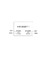
図24は、演出図柄表示装置230における表示の一例を示す画面402を示す説明図である。画面402は、持ち球数が異常である旨の報知をサブ統合制御装置520から指示された場合に表示される画面の一例である。画面402は、図22の画面401と同様に、演出図柄表示領域411,412,413と、表示領域422と、表示領域424とを備える。画面402における表示領域424は、持ち球数の表示に替えて、持ち球数が異常である旨を示す文字「異常」を表示する。 FIG. 24 is an explanatory diagram showing a screen 402 showing an example of display in the effect symbol display device 230. The screen 402 is an example of a screen displayed when the sub-integrated control device 520 instructs the notification that the number of balls held is abnormal. Similar to the screen 401 of FIG. 22, the screen 402 includes an effect symbol display area 411, 421, 413, a display area 422, and a display area 424. The display area 424 on the screen 402 displays the character "abnormal" indicating that the number of balls held is abnormal, instead of displaying the number of balls held.

〔枠側エラー報知処理〕
図25は、サブ統合制御装置520が実行する「枠側エラー報知処理」を示すフローチャートである。この「枠側エラー報知処理」は、枠制御装置560によって管理する機器の異常を演出図柄表示装置230において報知する処理である。サブ統合制御装置520は、枠側エラー報知処理を所定のタイミングで繰り返し実行する。枠側エラー報知処理を開始した後、サブ統合制御装置520は、枠制御装置560から枠側エラー情報(情報C3)を受信したか否かを判断する(ステップS732)。枠側エラー情報(情報C3)を受信した場合(ステップS732:「YES(異常)」、サブ統合制御装置520は、枠側エラー情報(情報C3)の報知を、演出図柄制御装置530を介して演出図柄表示装置230に指示する(ステップS734)。サブ統合制御装置520は、枠側エラー情報(情報C3)を報知する際、演出図柄表示装置230による報知に加え、スピーカ142の発光および発光部144の音出力による報知を指示してもよい。枠側エラー情報(情報C3)の報知を指示した後(ステップS734)、並びに、枠側エラー情報(情報C3)を受信していない場合(ステップS732:「NO(正常)」)、サブ統合制御装置520は、枠側エラー報知処理を終了する。
[Frame side error notification processing]
FIG. 25 is a flowchart showing the “frame-side error notification process” executed by the sub-integrated control device 520. This "frame-side error notification process" is a process of notifying the effect symbol display device 230 of an abnormality of the device managed by the frame control device 560. The sub-integrated control device 520 repeatedly executes the frame-side error notification process at a predetermined timing. After starting the frame-side error notification process, the sub-integrated control device 520 determines whether or not the frame-side error information (information C3) has been received from the frame control device 560 (step S732). When the frame side error information (information C3) is received (step S732: "YES (abnormality)", the sub-integrated control device 520 notifies the frame side error information (information C3) via the effect symbol control device 530. Instructing the effect symbol display device 230 (step S734). When the sub-integrated control device 520 notifies the frame side error information (information C3), the sub-integrated control device 520 emits light and emits light from the speaker 142 in addition to the notification by the effect symbol display device 230. Notification by sound output of 144 may be instructed. After instructing notification of frame-side error information (information C3) (step S734), and when frame-side error information (information C3) has not been received (step). S732: "NO (normal)"), the sub-integrated control device 520 ends the frame-side error notification process.

枠側エラー情報(情報C3)を報知する際(ステップS734)、枠制御装置560の制御に基づいて警報スピーカ354の音出力を実施してもよい。枠側エラー情報(情報C3)を報知する際、枠制御装置560の制御に基づいて発射装置310による遊技球の発射を停止し、遊技を不能にしてもよい。この場合、枠制御装置560は、遊技球の発射停止をサブ統合制御装置520に通知し、サブ統合制御装置520は、その旨の報知を演出図柄表示装置230に指示してもよい。 When notifying the frame side error information (information C3) (step S734), the sound output of the alarm speaker 354 may be performed based on the control of the frame control device 560. When notifying the frame side error information (information C3), the launching of the game ball by the launching device 310 may be stopped based on the control of the frame control device 560 to disable the game. In this case, the frame control device 560 may notify the sub-integrated control device 520 of the stop launch of the game ball, and the sub-integrated control device 520 may instruct the effect symbol display device 230 to notify to that effect.

図26は、演出図柄表示装置230における表示の一例を示す画面403を示す説明図である。画面403は、枠側エラー情報(情報C3)の報知をサブ統合制御装置520から指示された場合に表示される画面の一例である。画面403は、図22の画面401と同様に、演出図柄表示領域411,412,413と、表示領域422と、表示領域424とを備える。画面403は、更に、表示領域432を備える。表示領域432は、枠側エラー情報(情報C3)の内容を表示する領域である。図26の例では、表示領域432は、遊技球の循環系の異常を示す文字「球循環エラー」を表示する。 FIG. 26 is an explanatory diagram showing a screen 403 showing an example of display in the effect symbol display device 230. The screen 403 is an example of a screen displayed when the notification of the frame side error information (information C3) is instructed by the sub-integrated control device 520. Similar to the screen 401 of FIG. 22, the screen 403 includes an effect symbol display area 411, 421, 413, a display area 422, and a display area 424. The screen 403 further includes a display area 432. The display area 432 is an area for displaying the contents of the frame side error information (information C3). In the example of FIG. 26, the display area 432 displays the character “ball circulation error” indicating an abnormality in the circulatory system of the game ball.

〔夜間監視報知処理〕
図27は、サブ統合制御装置520が実行する「夜間監視報知処理」を示すフローチャートである。この「夜間監視報知処理」は、夜間監視装置352からの検知信号に基づく異常を演出図柄表示装置230において報知する処理である。サブ統合制御装置520は、パチンコ機10に対する電源が復帰する際、夜間監視報知処理を実行する。夜間監視報知処理を開始した後、サブ統合制御装置520は、枠制御装置560から夜間監視情報(情報C4)を受信したか否かを判断する(ステップS742)。パチンコ機10に対する電源が復帰する際、枠制御装置560は、夜間監視スイッチ夜間監視装置352から枠開放情報を取得し、その情報が内枠120の開放を示す場合、枠制御装置560は、夜間監視情報(情報C4)をサブ統合制御装置520に送信する。夜間監視情報(情報C4)は、パチンコ機10の電源遮断時に内枠120が開放された回数を示す情報を含んでもよいし、パチンコ機10の電源遮断時における内枠120の開放の有無を示す情報であってもよい。夜間監視情報(情報C4)を受信した場合(ステップS742:「YES(異常)」、サブ統合制御装置520は、夜間監視情報(情報C4)の報知を、演出図柄制御装置530を介して演出図柄表示装置230に指示する(ステップS744)。夜間監視情報(情報C4)の報知を指示した後(ステップS744)、並びに、夜間監視情報(情報C4)を受信していない場合(ステップS742:「NO(正常)」)、サブ統合制御装置520は、夜間監視報知処理を終了する。
[Night monitoring and notification processing]
FIG. 27 is a flowchart showing the “night monitoring / notification process” executed by the sub-integrated control device 520. This "nighttime monitoring / notification process" is a process of notifying the effect symbol display device 230 of an abnormality based on a detection signal from the nighttime monitoring device 352. The sub-integrated control device 520 executes nighttime monitoring and notification processing when the power to the pachinko machine 10 is restored. After starting the nighttime monitoring / notification process, the sub-integrated control device 520 determines whether or not nighttime monitoring information (information C4) has been received from the frame control device 560 (step S742). When the power to the pachinko machine 10 is restored, the frame control device 560 acquires the frame opening information from the night monitoring switch night monitoring device 352, and when the information indicates the opening of the inner frame 120, the frame control device 560 is at night. The monitoring information (information C4) is transmitted to the sub-integrated control device 520. The night monitoring information (information C4) may include information indicating the number of times the inner frame 120 is opened when the power of the pachinko machine 10 is cut off, or indicates whether or not the inner frame 120 is opened when the power of the pachinko machine 10 is turned off. It may be information. When the nighttime monitoring information (information C4) is received (step S742: "YES (abnormality)", the sub-integrated control device 520 notifies the nighttime monitoring information (information C4) via the effect symbol control device 530. Instruct the display device 230 (step S744). After instructing the notification of the night monitoring information (information C4) (step S744), and when the night monitoring information (information C4) is not received (step S742: "NO". (Normal) ”), the sub-integrated control device 520 ends the nighttime monitoring / notification process.

図28は、演出図柄表示装置230における表示の一例を示す画面404を示す説明図である。画面404は、夜間監視情報(情報C4)の報知をサブ統合制御装置520から指示された場合に表示される画面の一例である。画面404は、表示領域442を備える。表示領域442は、夜間監視情報(情報C4)の内容を表示する領域である。図28の例では、表示領域442は、パチンコ機10の稼動時間外(夜間)に内枠120が開放された異常を示す文字を表示する。 FIG. 28 is an explanatory diagram showing a screen 404 showing an example of display in the effect symbol display device 230. The screen 404 is an example of a screen displayed when the notification of nighttime monitoring information (information C4) is instructed by the sub-integrated control device 520. The screen 404 includes a display area 442. The display area 442 is an area for displaying the contents of nighttime monitoring information (information C4). In the example of FIG. 28, the display area 442 displays characters indicating an abnormality in which the inner frame 120 is opened outside the operating hours (nighttime) of the pachinko machine 10.

〔カード報知処理〕
図29は、サブ統合制御装置520が実行する「カード報知処理」を示すフローチャートである。この「カード報知処理」は、カードユニット80において記録カードを返却する旨を演出図柄表示装置230において報知する処理である。サブ統合制御装置520は、カード報知処理を所定のタイミングで繰り返し実行する。カード報知処理を開始した後、サブ統合制御装置520は、枠制御装置560からカード報知情報(情報C5)を受信したか否かを判断する(ステップS752)。返却ボタン813に操作入力があった場合、大当り遊技が終了する場合、計数スイッチ162に操作入力があった場合などの状況において、枠制御装置560は、カード報知情報(情報C5)をサブ統合制御装置520に送信する。カード報知情報(情報C5)を受信した場合(ステップS752:「YES」、サブ統合制御装置520は、カードユニット80において記録カードを返却する旨の報知を、演出図柄制御装置530を介して演出図柄表示装置230に指示する(ステップS754)。カードユニット80において記録カードを返却する旨の報知を指示した後(ステップS754)、並びに、カード報知情報(情報C5)を受信していない場合(ステップS752:「NO」)、サブ統合制御装置520は、カード報知処理を終了する。
[Card notification processing]
FIG. 29 is a flowchart showing a “card notification process” executed by the sub-integrated control device 520. This "card notification process" is a process of notifying the effect symbol display device 230 that the recording card will be returned by the card unit 80. The sub-integrated control device 520 repeatedly executes the card notification process at a predetermined timing. After starting the card notification process, the sub-integrated control device 520 determines whether or not the card notification information (information C5) has been received from the frame control device 560 (step S752). In situations such as when there is an operation input on the return button 813, when the jackpot game ends, or when there is an operation input on the counting switch 162, the frame control device 560 sub-integratedly controls the card notification information (information C5). It is transmitted to the device 520. When the card notification information (information C5) is received (step S752: "YES", the sub-integrated control device 520 notifies the card unit 80 that the recording card will be returned via the effect symbol control device 530. Instruct the display device 230 (step S754). After instructing the card unit 80 to notify that the recording card will be returned (step S754), and when the card notification information (information C5) has not been received (step S752). : "NO"), the sub-integrated control device 520 ends the card notification process.

大当り終了後に記録カードを返却する旨を報知する場合、サブ統合制御基板520は、主制御基板510からの情報に基づいて、記録カードを返却する旨を報知ができるため、枠制御基板560からカード報知情報を受信することなく、記録カードを返却する旨を報知してもよい。また、大当り終了毎に記録カードを返却する旨を報知する場合、記録カードを抜いているにも関わらず何回も報知することを回避するために、通常遊技状態からの大当り遊技状態が終了する場合にのみ、大当り終了後に記録カードを返却する旨を報知してもよい。枠制御装置560がカード報知情報を送信する場合においても同様である。 When notifying that the recording card will be returned after the jackpot is completed, the sub-integrated control board 520 can notify that the recording card will be returned based on the information from the main control board 510, so that the card is returned from the frame control board 560. You may notify that the recording card will be returned without receiving the notification information. In addition, when notifying that the recording card will be returned each time the jackpot ends, the jackpot gaming state from the normal gaming state ends in order to avoid notifying many times even though the recording card is removed. Only in case, it may be notified that the recording card will be returned after the jackpot is completed. The same applies when the frame control device 560 transmits the card notification information.

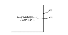
図30は、演出図柄表示装置230における表示の一例を示す画面405を示す説明図である。画面405は、カードユニット80において記録カードを返却する旨の報知をサブ統合制御装置520から指示された場合に表示される画面の一例である。画面405は、表示領域452を備える。表示領域452は、カードユニット80において記録カードを返却する旨を表示する領域である。図29の例では、表示領域442は、カードユニット80において記録カードを返却する旨を示す文字を表示する。 FIG. 30 is an explanatory diagram showing a screen 405 showing an example of display in the effect symbol display device 230. The screen 405 is an example of a screen displayed when the sub-integrated control device 520 instructs the card unit 80 to notify that the recording card will be returned. The screen 405 includes a display area 452. The display area 452 is an area for displaying that the recording card will be returned in the card unit 80. In the example of FIG. 29, the display area 442 displays characters indicating that the recording card will be returned in the card unit 80.

〔省エネ指示処理〕
図31は、枠制御装置560が実行する「省エネ指示処理」を示すフローチャートである。この「省エネ指示処理」は、サブ統合制御装置520に省エネ表示モードの実行を指示する処理である。省エネ表示モードは、通常時に実行される通常表示モードより少ない消費電力で発光部144および演出図柄表示装置230を動作させるモード(例えば、輝度抑制、消灯など)である。枠制御装置560は、省エネ指示処理を所定のタイミングで繰り返し実行する。省エネ指示処理を開始した後、枠制御装置560は、発射装置310において所定時間(例えば、5分間)、遊技球の発射がないか否かを判断する(ステップS662)。遊技球の発射がない場合(ステップS662:「YES」)、枠制御装置560は、枠制御装置560からの片方向通信でサブ統合制御装置520に省エネ表示モードの実行を指示する(ステップS664)。遊技球の発射がある場合(ステップS662:「NO」)、枠制御装置560は、枠制御装置560からの片方向通信でサブ統合制御装置520に通常表示モードの実行を指示する(ステップS666)。各表示モードの実行をサブ統合制御装置520に指示した後(ステップS664,S666)、枠制御装置560は、省エネ指示処理を終了する。
[Energy saving instruction processing]
FIG. 31 is a flowchart showing "energy saving instruction processing" executed by the frame control device 560. This "energy saving instruction process" is a process of instructing the sub-integrated control device 520 to execute the energy saving display mode. The energy-saving display mode is a mode in which the light emitting unit 144 and the effect symbol display device 230 are operated with less power consumption than the normal display mode executed in the normal time (for example, brightness suppression, extinguishing, etc.). The frame control device 560 repeatedly executes the energy saving instruction process at a predetermined timing. After starting the energy saving instruction process, the frame control device 560 determines whether or not the game ball is launched in the launching device 310 for a predetermined time (for example, 5 minutes) (step S662). When the game ball is not launched (step S662: “YES”), the frame control device 560 instructs the sub-integrated control device 520 to execute the energy saving display mode by one-way communication from the frame control device 560 (step S664). .. When the game ball is launched (step S662: “NO”), the frame control device 560 instructs the sub-integrated control device 520 to execute the normal display mode by one-way communication from the frame control device 560 (step S666). .. After instructing the sub-integrated control device 520 to execute each display mode (steps S664 and S666), the frame control device 560 ends the energy saving instruction process.

〔省エネ制御処理〕
図32は、サブ統合制御装置520が実行する「省エネ制御処理」を示すフローチャートである。この「省エネ制御処理」は、発光部144および演出図柄表示装置230を省エネ表示モードで制御する処理である。サブ統合制御装置520は、省エネ制御処理を所定のタイミングで繰り返し実行する。省エネ制御処理を開始した後、サブ統合制御装置520は、枠制御装置560から省エネ表示モードの指示があるか否かを判断する(ステップS762)。省エネ表示モードの指示がある場合(ステップS762:「YES」)、サブ統合制御装置520は、発光部144および演出図柄表示装置230を省エネ表示モードで制御する(ステップS764)。省エネ表示モードの指示がない場合(ステップS762:「NO」)、サブ統合制御装置520は、発光部144および演出図柄表示装置230を通常表示モードで制御する(ステップS766)。各表示モードによる制御を有効にした後(ステップS764,S766)、サブ統合制御装置520は、省エネ制御処理を終了する。
[Energy saving control processing]
FIG. 32 is a flowchart showing the “energy saving control process” executed by the sub-integrated control device 520. This "energy-saving control process" is a process of controlling the light emitting unit 144 and the effect symbol display device 230 in the energy-saving display mode. The sub-integrated control device 520 repeatedly executes the energy-saving control process at a predetermined timing. After starting the energy-saving control process, the sub-integrated control device 520 determines whether or not there is an instruction of the energy-saving display mode from the frame control device 560 (step S762). When there is an instruction for the energy-saving display mode (step S762: “YES”), the sub-integrated control device 520 controls the light emitting unit 144 and the effect symbol display device 230 in the energy-saving display mode (step S764). When there is no instruction for the energy-saving display mode (step S762: “NO”), the sub-integrated control device 520 controls the light emitting unit 144 and the effect symbol display device 230 in the normal display mode (step S766). After enabling the control by each display mode (steps S746 and S766), the sub-integrated control device 520 ends the energy-saving control process.

〔累計貸球数演算処理〕
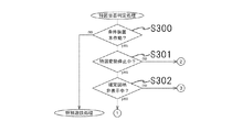
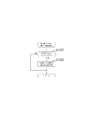
図33は、枠制御装置560が実行する「累計貸球数演算処理」を示すフローチャートである。本処理は定期的に実行される。
本処理では、先ず、カードユニット80から送信されるデータが貸球数を示すデータか否か判断する(ステップS800)。貸球数を示すデータの場合、記憶している累計貸球数に受信した貸球数を加算する処理を行う(ステップS801)。この処理は、前述したステップS614の持ち球数管理処理とは別個の処理であり、持ち球数とは異なる記憶領域に累計貸球数は記憶される。
累計貸球数は、パチンコ機10で遊技が行われていないときには、その値は零クリアされている。従って、カードユニット80のカード挿入口820又は紙幣挿入口830に記録カード又は紙幣が挿入され、球貸ボタン812が操作される迄は、累計貸球数の値は零である。
カードユニット80のカード挿入口820又は紙幣挿入口830に記録カード又は紙幣を挿入し、球貸ボタン812を操作したときに枠制御装置560が受信する貸球数は、遊技開始時の貸球数であると同時に累計貸球数となる。
遊技を開始した後、持ち球数が少なくなり新たに球貸ボタン812を操作して貸球を得る場合、持ち球数が零になり遊技を終了させる迄の間に新たに貸球を得る場合の追加の貸球数が累計貸球数に加算される。なお、遊技が終了した場合には、累計貸球数は零クリアされるが、これについては後述する。
累計貸球数に受信した貸球数を加算する処理を行った後、累計貸球数に基づく演出処理を実行する(ステップS802)。
なお、記憶する累計球貸数は、対応する累計投入金額を示すデータとして記憶しても良い。
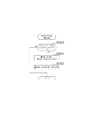
[Cumulative number of loaned balls calculation processing]
FIG. 33 is a flowchart showing the “cumulative number of loaned balls calculation process” executed by the frame control device 560. This process is executed periodically.
In this process, first, it is determined whether or not the data transmitted from the card unit 80 is data indicating the number of rented balls (step S800). In the case of data indicating the number of rented balls, a process of adding the number of rented balls received to the stored cumulative number of rented balls is performed (step S801). This process is separate from the ball holding number management process in step S614 described above, and the cumulative number of balls lent is stored in a storage area different from the ball holding number.
The cumulative number of balls rented is cleared to zero when no game is being played on the pachinko machine 10. Therefore, the value of the cumulative number of balls to be lent is zero until the recording card or the banknote is inserted into the card insertion slot 820 or the bill insertion slot 830 of the card unit 80 and the ball lending button 812 is operated.
When a recording card or bill is inserted into the card insertion slot 820 or bill insertion slot 830 of the card unit 80 and the ball lending button 812 is operated, the number of ball lending received by the frame control device 560 is the number of ball lending at the start of the game. At the same time, it becomes the cumulative number of balls lent.
After starting the game, when the number of balls held decreases and a new ball lending button 812 is operated to obtain a new ball lending, or when the number of balls held becomes zero and a new ball lending is obtained before the game ends. The additional number of balls lent is added to the cumulative number of balls lent. When the game is over, the cumulative number of balls lent will be cleared to zero, which will be described later.
After performing a process of adding the received number of balls to the total number of balls to be rented, an effect process based on the total number of rented balls is executed (step S802).
The cumulative number of ball loans to be stored may be stored as data indicating the corresponding cumulative input amount.
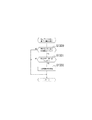
〔累計貸球数に基づく演出処理〕
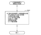
図34は、前記S802に示す演出処理の一例である「累計貸球数に基づく演出処理1」を示すフローチャートである。
本処理では、予め定められたタイミングと判断されたとき(ステップS805)、演出図柄表示装置230の画面上に累計貸球数及び/又は累計投入金額を表示する処理(ステップS806)が行われる。
この表示の一例を図35に示す。
図35には、持ち球数を示す文字図柄424、文字図柄424が示す持ち球数に対応する金額を示す文字図柄424m、累計貸球数を示す文字図柄460及び文字図柄460が示す累計貸球数に対応する金額を示す文字図柄460mが表示されている。
文字図柄460mが示す金額は、遊技開始時から球貸ボタン812を操作することにより遊技に使用する金額の総量(以下、「累計投入金額」ということもある。)を示す。これは、累計貸球数に貸球1個の単価を乗算することにより得られる。通常は、貸球1個に対して4円の遊技使用料が発生する。
文字図柄424mが示す金額は、持ち球数に持ち球1個の換金単価を乗算することにより得られる。所謂「等価交換」の場合は、持ち球1個に対して4円である。等価交換でない場合には、4円未満とするのが一般的である。
貸球1個の単価又は持ち球1個の換金単価は、カードユニット80から送信しても良く、パチンコ機10で操作により選択又は設定する構成でも良い。パチンコ機10で選択又は設定する構成の場合、サブ統合制御装置520又は演出図柄制御装置530で設定する構成が好適である。
[Direction processing based on the cumulative number of balls lent]
FIG. 34 is a flowchart showing "effect processing 1 based on the cumulative number of balls lent", which is an example of the effect processing shown in S802.
In this process, when it is determined that the timing is predetermined (step S805), a process of displaying the cumulative number of balls lent and / or the cumulative input amount on the screen of the effect symbol display device 230 (step S806) is performed.
An example of this display is shown in FIG.
In FIG. 35, a character symbol 424 indicating the number of balls held, a character symbol 424 m indicating the amount of money corresponding to the number of balls held by the character symbol 424, a character symbol 460 indicating the cumulative number of balls lent, and a cumulative ball renting indicated by the character symbol 460. A character symbol 460 m indicating the amount of money corresponding to the number is displayed.
The amount of money indicated by the character symbol 460m indicates the total amount of money used for the game by operating the ball lending button 812 from the start of the game (hereinafter, may be referred to as "cumulative input amount"). This is obtained by multiplying the cumulative number of rented balls by the unit price of one rented ball. Normally, a game usage fee of 4 yen is incurred for each rental ball.
The amount of money indicated by the character symbol 424m is obtained by multiplying the number of balls held by the cash unit price of one ball held. In the case of so-called "equivalent exchange", it is 4 yen for one holding ball. If it is not an equivalent exchange, it is generally less than 4 yen.
The unit price of one lending ball or the cashing unit price of one holding ball may be transmitted from the card unit 80, or may be selected or set by operation with the pachinko machine 10. In the case of the configuration selected or set by the pachinko machine 10, the configuration set by the sub-integrated control device 520 or the effect symbol control device 530 is preferable.

前記ステップS805に示す予め定められたタイミングは、遊技者が球貸ボタン812を操作したとき、大当たり遊技が終了したとき、確変遊技又は時短遊技等の特典遊技が終了したとき、又は所定数(例えば、1000個)の持ち球数が減少したとき等が考えられる。但し、常時表示しても何等問題ない。
前記予め定められたタイミングは主制御装置510が判断し、サブ統合制御装置520にステップS806の表示コマンドを出力する構成が考えられる。
累計貸球数を示すデータは、枠制御装置560からサブ統合制御装置520に直接出力しても良く、枠制御装置560から主制御装置510を介してサブ統合制御装置520に出力しても良い。
なお、本処理では、文字図柄424、文字図柄424m、文字図柄460及び文字図柄460mを表示するよう構成したが、必ずしも全て表示する必要はなく、少なくとも文字図柄460を表示すれば良い。
The predetermined timing shown in step S805 is when the player operates the ball lending button 812, when the jackpot game ends, when the privilege game such as the probability variation game or the time saving game ends, or a predetermined number (for example). , 1000) It is conceivable that the number of balls held decreases. However, there is no problem even if it is always displayed.
A configuration is conceivable in which the main control device 510 determines the predetermined timing and outputs the display command of step S806 to the sub-integrated control device 520.
The data indicating the cumulative number of balls to be rented may be output directly from the frame control device 560 to the sub-integrated control device 520, or may be output from the frame control device 560 to the sub-integrated control device 520 via the main control device 510. ..
In this process, the character symbol 424, the character symbol 424 m, the character symbol 460, and the character symbol 460 m are configured to be displayed, but it is not always necessary to display all of them, and at least the character symbol 460 may be displayed.

累計貸球数に基づく演出処理1を実行することにより、持ち球数に含まれる累計貸球数を知ることができる。これにより、持ち球数から累計貸球数を差し引いた球数、即ち、遊技により獲得した持ち球数を知ることができる効果を発揮する。遊技者は遊技に使用した投入金額も知ることができるので、遊技による収支決算額も容易に認識することができる。
また、持ち球数が増加している大当たり遊技又は特典遊技が終了したとき、累計貸球数又は累計投入金額を認識すれば、持ち球数と比較して遊技の止め時が促されることも期待できる。さらに、持ち球数が所定個数以上減少したとき、累計貸球数又は累計投入金額を認識すれば、遊技の止め時が促されることも期待できる。
なお、本処理では、累計球貸数に基づき演出処理を実行する構成だが、単に遊技開始時の球貸数又は遊技中の追加球貸数を表示するよう構成しても良い。
By executing the effect process 1 based on the cumulative number of balls lent, the cumulative number of balls lent included in the number of balls held can be known. As a result, the number of balls held by subtracting the cumulative number of balls lent from the number of balls held, that is, the number of balls held by the game can be known. Since the player can also know the amount of money input for the game, he / she can easily recognize the balance settlement amount due to the game.
In addition, when the jackpot game or bonus game in which the number of balls held is increasing, if the cumulative number of balls lent or the total amount of money input is recognized, it is expected that the game will be stopped in comparison with the number of balls held. it can. Furthermore, when the number of balls held decreases by a predetermined number or more, it can be expected that the time to stop the game will be promoted if the cumulative number of balls lent or the cumulative amount of money input is recognized.
In this process, the effect processing is executed based on the cumulative number of balls lent, but the number of balls lent at the start of the game or the number of additional balls lent during the game may be simply displayed.

図36は、前記S802に示す演出処理の一例である「累計貸球数に基づく演出処理2」を示すフローチャートである。
本処理では、累計球貸数が所定個数NB3(例えば、1000個)以上か否か判断され(ステップS810)、所定個数NB3以上であれば、続けて大当たりの設定確率が所定値以上か否か判断される(ステップS811)。
前述したように、本実施形態では、段階設定値が「1」のとき、通常状態での設定確率は1/300、確変状態での設定確率は1/30に設定され、段階設定値が「6」のとき、通常状態での設定確率は1/250に設定されると共に、確変状態での設定確率は1/25に設定され、段階設定値が大きい程に設定確率は高くなるよう構成されている。
本処理では、6段階の段階設定値が3以上であれば、設定確率示唆演出を行う(ステップS812)。但し、これは、一例であり、段階設定値が2以上のとき設定確率示唆演出を行っても良い。
FIG. 36 is a flowchart showing “effect processing 2 based on the cumulative number of rented balls”, which is an example of the effect processing shown in S802.
In this process, it is determined whether or not the cumulative number of balls lent is NB3 (for example, 1000) or more (step S810), and if the cumulative number of balls is NB3 or more, whether or not the jackpot setting probability is continuously set to a predetermined value or more. It is determined (step S811).
As described above, in the present embodiment, when the step setting value is "1", the setting probability in the normal state is set to 1/300, the setting probability in the probability variation state is set to 1/30, and the step setting value is "1". In the case of "6", the setting probability in the normal state is set to 1/250, the setting probability in the probability variation state is set to 1/25, and the setting probability becomes higher as the step setting value is larger. ing.
In this process, if the step setting value of the six steps is 3 or more, the setting probability suggestion effect is performed (step S812). However, this is an example, and the setting probability suggestion effect may be performed when the stage setting value is 2 or more.

設定確率を示唆する演出は、図37に示すように、特定のキャラクタ図柄CYを演出図柄表示装置230の画面上に出現させることにより行われる。
設定確率を示唆する演出は、「運が良いかも?」又は「当り易いかも?」といった高確率を示唆する文字図柄LEであっても良い。また、設定確率を示唆する演出は、判別容易に行ってもよいが、注意深く観察しないと判別できない態様であっても良い。例えば、一瞬表示させても良いし、単に通常表示されるキャラクタ図柄の色、形状又は動作を変化させる演出であっても良く、その演出態様は問われない。これらのキャラクタ図柄CY、文字図柄LEは、画面上に一方のみ表示してもよく、両方を表示しても良い。
なお、累計貸球数が所定個数以上か否かの判断を段階的に実行し、累計貸球数が大きくなる程、設定確率の示唆演出を明確に行う等して演出態様を変化させるよう構成しても良い。
As shown in FIG. 37, the effect suggesting the setting probability is performed by causing a specific character symbol CY to appear on the screen of the effect symbol display device 230.
The effect suggesting the setting probability may be a character symbol LE suggesting a high probability such as "maybe you are lucky?" Or "maybe you are easy to hit?". Further, the effect of suggesting the setting probability may be easily discriminated, but may be in a mode that cannot be discriminated without careful observation. For example, it may be displayed for a moment, or it may be an effect that simply changes the color, shape, or movement of the normally displayed character symbol, and the effect mode is not limited. Only one of these character symbol CY and character symbol LE may be displayed on the screen, or both may be displayed.
In addition, it is configured to gradually determine whether or not the cumulative number of balls lent is equal to or greater than the predetermined number, and to change the production mode by clearly performing the suggestion effect of the setting probability as the cumulative number of balls lent increases. You may.

本処理を実行することにより、遊技開始時から遊技終了迄の累計貸球数、又はこれに対応する累計投入金額を遊技者に認識させることが可能となる。
追加する貸球数が多くなる程、遊技に投入する金額が高額になるが、このとき、設定確率が高い設定であれば、その旨を示唆する演出を行えば、損失を挽回できる可能性が高いことを遊技者に知らせる効果を発揮する。追加する貸球数が多くなっても、設定確率を示唆する演出が行わなければ、設定確率が低いことを推測でき、遊技者に遊技を止めることを促す効果も期待できる。
また、累計の投資金額に応じた設定確率の示唆演出を行うことができ、パチンコ機10に多くの投資金額を使用する遊技者、パチンコ機10で多くの時間遊技を行う遊技者に設定確率の示唆という特典を付与することができる効果も有する。
By executing this process, it is possible for the player to recognize the cumulative number of balls lent from the start of the game to the end of the game, or the cumulative amount of money input corresponding thereto.
As the number of balls to be added increases, the amount of money to be invested in the game becomes higher, but at this time, if the setting probability is high, there is a possibility that the loss can be recovered by performing an effect suggesting that fact. It has the effect of notifying the player that it is expensive. Even if the number of balls to be added increases, if the effect suggesting the setting probability is not performed, it can be inferred that the setting probability is low, and the effect of encouraging the player to stop the game can be expected.
In addition, it is possible to suggest a setting probability according to the cumulative investment amount, and the set probability can be set for a player who spends a lot of investment amount on the pachinko machine 10 and a player who plays a lot of time on the pachinko machine 10. It also has the effect of giving the privilege of suggestion.

図36に示す処理は、サブ統合制御装置520又は演出図柄制御装置530により実行するよう構成することができる。設定確率を示すデータは、電源投入時又は設定確率が変更されたとき、主制御装置510からサブ統合制御装置520又は演出図柄制御装置530に送信される。また、累計球貸数は、枠制御装置560からサブ統合制御装置520又は演出図柄制御装置530に定期的に出力される。
但し、この構成に限定されることはない、例えば、主制御装置510から枠制御装置560に設定確率を示すデータを送信しておき、ステップS810〜S820に示す処理を枠制御装置560が実行し、ステップS812を実行するコマンドを枠制御装置560からサブ統合制御装置520又は演出図柄制御装置530に出力するよう構成しても良い。
或は、累計貸球数を示すデータを、枠制御装置560から主制御装置510に定期的に送信し、主制御装置がS810〜S820に示す処理を実行し、ステップS812を実行するコマンドを主制御装置510からサブ統合制御装置520又は演出図柄制御装置530に出力するよう構成しても良い。
図34に示した「累計貸球数に基づく演出処理1」も同様であり、主制御装置510、枠制御装置560及びサブ統合制御装置520(延いては演出図柄制御装置530)との装置相互間の回路構成の相違により、ステップS805及びS806の各処理を実行する装置を選択すれば良い。
The process shown in FIG. 36 can be configured to be executed by the sub-integrated control device 520 or the effect symbol control device 530. The data indicating the setting probability is transmitted from the main control device 510 to the sub integrated control device 520 or the effect symbol control device 530 when the power is turned on or when the setting probability is changed. Further, the cumulative number of balls lent is periodically output from the frame control device 560 to the sub-integrated control device 520 or the effect symbol control device 530.
However, the configuration is not limited to this, for example, data indicating the setting probability is transmitted from the main control device 510 to the frame control device 560, and the frame control device 560 executes the processes shown in steps S810 to S820. , The command for executing step S812 may be output from the frame control device 560 to the sub-integrated control device 520 or the effect symbol control device 530.
Alternatively, the main command is to periodically transmit data indicating the cumulative number of ball rentals from the frame control device 560 to the main control device 510, the main control device executes the processes shown in S810 to S820, and execute step S812. The control device 510 may be configured to output to the sub-integrated control device 520 or the effect symbol control device 530.
The same applies to the “effect processing 1 based on the cumulative number of balls rented” shown in FIG. 34, which is the same as that of the main control device 510, the frame control device 560, and the sub-integrated control device 520 (and the effect symbol control device 530). The device that executes each of the processes of steps S805 and S806 may be selected depending on the difference in the circuit configuration between the two.

〔累計貸球数送信処理〕
図38は、枠制御装置560が実行する「累計貸球数送信処理」を示すフローチャートである。
本処理では、先ず、遊技が終了したか否か判断される。
遊技が終了したことは、返却ボタン813が操作されたことの信号をカードユニット80から受信すること、計数スイッチ160が操作され持ち球数が零になったこと、又は遊技中に持ち球数が零になり遊技が所定時間行われていないこと、により判断される。これらの判断は、2つ以上組み合わせて判断しても良い。
遊技が行われていない判断は、枠制御装置560が発射入口センサ315又はアウト球センサ345により所定時間(例えば、3分間)以上遊技球が発射されていないことを検出して判断することができる。また、主制御装置510が各入賞口271〜274への入賞状態を検出して判断し、判断結果を枠制御装置560に送信するよう構成しても良い。
[Cumulative number of loaned balls transmission process]
FIG. 38 is a flowchart showing the “cumulative number of loaned balls transmission process” executed by the frame control device 560.
In this process, first, it is determined whether or not the game is completed.
The end of the game means that the card unit 80 receives a signal that the return button 813 has been operated, that the counting switch 160 has been operated and the number of balls held has become zero, or that the number of balls held during the game has been reduced. It is judged by the fact that the game becomes zero and the game has not been performed for a predetermined time. These judgments may be judged in combination of two or more.
The determination that the game is not performed can be determined by detecting that the frame control device 560 has not launched the game ball for a predetermined time (for example, 3 minutes) or more by the launch inlet sensor 315 or the out ball sensor 345. .. Further, the main control device 510 may be configured to detect and determine the winning state of each winning opening 271-274 and transmit the determination result to the frame control device 560.

遊技終了と判断されると(ステップS815)、枠制御装置560が記憶する累計貸球数を示すデータがカードユニット80に出力され(ステップS816)、その後、累計貸球数は零クリアされる(ステップS817)。
なお、図38に示す処理では、同一人の遊技開始から遊技終了までの累計貸球数を示すデータをカードユニット80に出力するよう構成したが、遊技終了時だけでなく、定期的(例えば、30分毎)に送信するよう構成しても良い。また、同一人の遊技開始から遊技終了までの累計貸球数だけでなく、複数人による累計貸球数を示すデータを送信するよう構成しても良い。例えば、電源投入時(開店時)から閉店時までの累計貸球数を示すデータをカードユニット80に送信するよう構成しても良い。この場合には、開店時から閉店時までの累計貸球数を示すデータも記憶されることになる。
開店時から閉店時までの累計貸球数をユニットに送信するよう構成すれば、カードユニット80による1日の売上と比較照合できる効果を発揮する。
When it is determined that the game is completed (step S815), the data indicating the cumulative number of balls lent stored in the frame control device 560 is output to the card unit 80 (step S816), and then the cumulative number of rented balls is cleared to zero (step S816). Step S817).
In the process shown in FIG. 38, data indicating the cumulative number of balls lent from the start of the game to the end of the game of the same person is output to the card unit 80, but not only at the end of the game but also periodically (for example, for example). It may be configured to transmit every 30 minutes). Further, not only the cumulative number of balls lent by the same person from the start of the game to the end of the game, but also data indicating the cumulative number of rented balls by a plurality of players may be transmitted. For example, data indicating the cumulative number of balls rented from the time the power is turned on (when the store is opened) to the time when the store is closed may be transmitted to the card unit 80. In this case, data indicating the cumulative number of balls rented from the time the store is opened to the time the store is closed is also stored.
If the cumulative number of balls rented from the time the store is opened to the time the store is closed is configured to be transmitted to the unit, the effect of being able to compare and collate with the daily sales of the card unit 80 is exhibited.

本処理を実行することにより、カードユニット80の球貸ボタン812の操作による総貸球数と、パチンコ機10の枠制御装置560に記憶した累計貸球数とをカードユニット80が比較照合することが可能となる。この結果、記憶媒体である記録カードの信頼性を高める効果に寄与する効果を発揮する。記録カードの信頼性を損なう原因としては、ノイズ等によるデータの変化、パチンコ機10を接続したカードユニット80の外部からの不正行為等が考えられる。
また、紙幣により遊技を行った場合でも、カードユニット80の球貸ボタン812の操作による総貸球数と、パチンコ機10の枠制御装置560に記憶した累計貸球数とをカードユニット80が比較照合することが可能なので、パチンコ機10に対して電波ゴト等の不正行為により貸球を得る等の不正行為を検出することも期待できる。
By executing this process, the card unit 80 compares and collates the total number of balls lent by operating the ball lending button 812 of the card unit 80 with the cumulative number of balls lent stored in the frame control device 560 of the pachinko machine 10. Is possible. As a result, the effect of contributing to the effect of increasing the reliability of the recording card, which is a storage medium, is exhibited. Possible causes of impairing the reliability of the recording card include changes in data due to noise and the like, fraudulent acts from the outside of the card unit 80 to which the pachinko machine 10 is connected, and the like.
Further, even when the game is played with banknotes, the card unit 80 compares the total number of balls lent by operating the ball lending button 812 of the card unit 80 with the cumulative number of balls lent stored in the frame control device 560 of the pachinko machine 10. Since it is possible to collate, it can be expected to detect fraudulent acts such as obtaining a ball loan for the pachinko machine 10 due to fraudulent acts such as radio wave goto.

〔メダルレス回胴式遊技機〕
〔第2実施形態〕
第2実施形態は、本願発明の管理遊技機を回胴式遊技機に適用したメダルレス回胴式遊技機の具体例である。
〔全体の構成〕
図39に示すように、本実施形態の回胴式遊技機1001の前面には表示窓1002(3×3の停止図柄の有効領域を表示可能とする)を備えた表示パネル1003が設けられている。この回胴式遊技機1001は、実際の遊技メダル(以下、単に「メダル」という)を使用せず、データとしての持ちメダル数(持コイン数)で遊技を行うメダルレス(コインレス)回胴式遊技機として構成されている。
なお、メダルをコインとも言うが、本実施形態では、遊技規則に則り以下、メダルという。
[Medalless rotating game machine]
[Second Embodiment]
The second embodiment is a specific example of a medalless rotating cylinder type gaming machine in which the managed gaming machine of the present invention is applied to the rotating cylinder type gaming machine.
[Overall configuration]
As shown in FIG. 39, a display panel 1003 provided with a display window 1002 (which makes it possible to display an effective area of a 3 × 3 stop symbol) is provided on the front surface of the rotating cylinder type game machine 1001 of the present embodiment. There is. This rotating cylinder type game machine 1001 does not use actual game medals (hereinafter, simply referred to as "medals"), and plays a game based on the number of medals (the number of coins possessed) as data. It is configured as a machine.
The medal is also referred to as a coin, but in the present embodiment, the medal is hereinafter referred to as a medal in accordance with the game rules.

表示窓1002の背後には回胴である3本のリール1004(それぞれを区別する場合は、左から順にリール1004L、1004C、1004R、その他の部品等についても左、中、右を区別する場合は符号にL、C、Rを添える。)を有する図示しない回胴機構部が配されており、各リール1004に設けられている図柄の中の3図柄ずつを表示窓1002から視認できる。また、表示窓1002の周囲にはベットランプ1005や複数のデジタル表示装置1006等が配されている。 Behind the display window 1002 are three reels 1004 that are reels (when distinguishing each, reels 1004L, 1004C, 1004R, and other parts are also distinguished from left, middle, and right in order from the left. A rotating cylinder mechanism portion (not shown) having (L, C, R is added to the reference numerals) is arranged, and three symbols among the symbols provided on each reel 1004 can be visually recognized from the display window 1002. Further, a bed lamp 1005, a plurality of digital display devices 1006, and the like are arranged around the display window 1002.

表示窓1002の下方には、ベットボタン1007、始動レバー1008、3つの停止ボタン10099(それぞれを区別する場合は、左から順に停止ボタン1009L、1009C、1009R)等を備える操作部1011が設けられている。なお、ベットボタン1007は、3枚ベット(賭)機能に加えて、1枚ベット機能、及び2枚ベット機能も含まれている。
なお、ベット機能は、いずれかの機構1個の構成でも良い。
Below the display window 1002, an operation unit 1011 provided with a bet button 1007, a start lever 1008, three stop buttons 10099 (when distinguishing them, stop buttons 1009L, 1009C, 1009R in order from the left) and the like are provided. There is. The bet button 1007 includes a 1-card bet function and a 2-card bet function in addition to the 3-card bet (bet) function.
The betting function may be configured by any one mechanism.

さらに下方にはスピーカボックス1013、遊技可能な持ちメダル数を表示する持ちメダル数表示装置1051を備える下部構造部1014が設けられている。 Further below, a speaker box 1013 and a lower structure portion 1014 including a medal number display device 1051 for displaying the number of medals that can be played are provided.

また、本実施形態の回胴式遊技機1001は、ICカードの読み書きなどを行うカードユニット(CRユニット)1056が隣接されている。CRユニット1056には、ICカードを挿入および取り出し可能なカード挿入口1059と、紙幣を挿入可能な紙幣挿入口1058とを備え、さらに、該CRユニット1056の下部から右方へ突出するように、ユニット表示装置1057が設けられている。このユニット表示装置1057は、タッチパネル式のLCD画面を備え、該画面に、前記カード挿入口1059に挿入されたICカードに記憶されたクレジット残高(又は、クレジット残高内で貸出可能なメダル数)などが表示される。そして、このクレジット残高(又は、貸出可能なメダル数)は、メダルの貸出や返却に応じて更新される。このユニット表示装置1057の表示態様については、その詳細を後述する。 Further, the rotating cylinder type game machine 1001 of the present embodiment is adjacent to a card unit (CR unit) 1056 that reads and writes IC cards. The CR unit 1056 is provided with a card insertion slot 1059 into which an IC card can be inserted and removed, and a bill insertion slot 1058 into which a bill can be inserted, and further, so as to project from the lower portion of the CR unit 1056 to the right. A unit display device 1057 is provided. The unit display device 1057 is provided with a touch panel type LCD screen, and the credit balance (or the number of medals that can be lent within the credit balance) stored in the IC card inserted in the card insertion slot 1059 is displayed on the screen. Is displayed. Then, this credit balance (or the number of medals that can be lent out) is updated according to the lending or returning of medals. The details of the display mode of the unit display device 1057 will be described later.

また、図40に示すように、回胴式遊技機1001は、CRユニット1056を介してホールコンピュータ(遊技店の管理コンピュータ)1070に接続され、さらに、広域ネットワークを介して外部の情報管理センタに接続されている(図示せず)。これにより、各回胴式遊技機1001は、夫々の認証情報に基づいて、メーカーからの出荷情報、設置された遊技店の情報、遊技店間での移動情報、廃棄情報等が管理され、不正な使用や不正な改造などを防ぐ高いセキュリティ能力を有している。こうした回胴式遊技機1001は、管理遊技機とも呼ばれている。 Further, as shown in FIG. 40, the rotating cylinder type game machine 1001 is connected to the hall computer (game store management computer) 1070 via the CR unit 1056, and further to an external information management center via a wide area network. Connected (not shown). As a result, each round-body game machine 1001 manages shipping information from the manufacturer, information on the installed game stores, information on movement between game stores, disposal information, etc. based on the respective authentication information, and is illegal. It has a high security ability to prevent use and unauthorized modification. Such a rotating game machine 1001 is also called a managed game machine.

〔電気的構成〕
回胴式遊技機1001の電気的接続は、図40に示す通りに構成されており、主制御装置1040はCPU、ROM、RAM1040a、入力ポート、出力ポート等を備えている。本実施形態では、RAM1040aのみ図示する。
[Electrical configuration]
The electrical connection of the rotary gaming machine 1001 is configured as shown in FIG. 40, and the main control device 1040 includes a CPU, a ROM, a RAM 1040a, an input port, an output port, and the like. In this embodiment, only the RAM 1040a is shown.

また、主制御装置1040には、ベットボタン1007の操作信号、始動レバー1008の操作信号(始動信号)、停止ボタン1009L〜Rの操作信号(停止信号)、各リール1004の位置検出センサ1041の信号等が入力される。 Further, the main control device 1040 has an operation signal of the bet button 1007, an operation signal of the start lever 1008 (start signal), an operation signal of the stop buttons 1009L to R (stop signal), and a signal of the position detection sensor 1041 of each reel 1004. Etc. are input.

さらに、主制御装置1040の出力側には、ベット数(賭数)表示装置1043、加算メダル(コイン)数表示装置1044、RBゲーム数表示装置1045、RB実行数表示装置1046、カウント数表示装置1047、リール1004を回動させる駆動モータ1028L、1028C、1028R、リール1004を発光させる投光ランプ1031L、1031C、1031R、及び中継基板1048、が接続されている。なお、ベット数表示装置1043は、遊技者の持ちメダル数にかかわらず単にベット操作に基づいて1ゲーム(遊技)毎に消化されるメダル数を表示するものである。なお、ベット数表示装置1043は、後述する枠制御装置1050に接続しても良い。また、加算メダル数表示装置1044は、遊技者の持ちメダル数にかかわらず単に入賞の結果加算されるメダル数を表示するものである。さらに、カウント数表示装置1047は、遊技者の持ちメダル数にかかわらず電源投入後のゲーム数をカウント表示するものである。これらベット数表示装置1043、加算メダル数表示装置1044、又はカウント数表示装置1047は例えばデジタル表示装置1006で表示されてもよいし、回胴式遊技機1001とは別の外部表示装置で表示されてもよい。 Further, on the output side of the main control device 1040, a bet number (bet number) display device 1043, an additional medal (coin) number display device 1044, an RB game number display device 1045, an RB execution number display device 1046, and a count number display device 1047, a drive motor 1028L, 1028C, 1028R for rotating the reel 1004, floodlight lamps 1031L, 1031C, 1031R for emitting light on the reel 1004, and a relay board 1048 are connected. The bet number display device 1043 displays the number of medals to be consumed for each game (game) simply based on the bet operation regardless of the number of medals held by the player. The bet number display device 1043 may be connected to the frame control device 1050 described later. Further, the additional medal number display device 1044 simply displays the number of medals to be added as a result of winning regardless of the number of medals possessed by the player. Further, the count number display device 1047 counts and displays the number of games after the power is turned on regardless of the number of medals held by the player. The bet number display device 1043, the additional medal number display device 1044, or the count number display device 1047 may be displayed on, for example, the digital display device 1006, or may be displayed on an external display device different from the rotating cylinder type game machine 1001. You may.

また、主制御装置1040は、CPUがプログラムに従って動作することにより、ベット数表示装置1043、加算メダル数表示装置1044、RBゲーム数表示装置1045、RB実行数表示装置1046、カウント数表示装置1047の表示、駆動モータ1028の回転及び停止、並びに、投光ランプの点灯及び消灯等を制御する。 Further, in the main control device 1040, when the CPU operates according to the program, the bet number display device 1043, the additional medal number display device 1044, the RB game number display device 1045, the RB execution number display device 1046, and the count number display device 1047. It controls the display, the rotation and stop of the drive motor 1028, and the lighting and extinguishing of the floodlight lamp.

中継基板1048には音・ランプ制御装置1049が接続されており、主制御装置1040は中継基板1048経由で音・ランプ制御装置1049に指令データを送ることで、効果音などの音声出力と電飾類の点灯及び消灯を間接的に制御する。
音・ランプ制御装置1049は、サブ統合制御装置と呼ばれることもある。
A sound / lamp control device 1049 is connected to the relay board 1048, and the main control device 1040 sends command data to the sound / lamp control device 1049 via the relay board 1048 to output sound effects and other sounds and lights up. It indirectly controls the on and off of the kind.
The sound / lamp control device 1049 is sometimes called a sub-integrated control device.

音・ランプ制御装置1049には、演出画像表示装置1090を制御するための演出画像制御装置1091が接続される。演出画像制御装置1091は、主制御装置1040が中継基板1048に送出した指令データ又はこのデータに基づいて音・ランプ制御装置1049が生成したデータを受信し、これに従って演出画像表示装置1090を制御する。 An effect image control device 1091 for controlling the effect image display device 1090 is connected to the sound / lamp control device 1049. The effect image control device 1091 receives the command data sent by the main control device 1040 to the relay board 1048 or the data generated by the sound / lamp control device 1049 based on this data, and controls the effect image display device 1090 accordingly. ..

なお、加算メダル数表示装置1044、RBゲーム数表示装置1045、RB実行数表示装置1046及びカウント数表示装置1047のいずれか又は全部を廃して、その表示を演出画像表示装置1090にて行ってもよい。
また、主制御装置1040は、メイン制御基板とサブ制御基板とによって構成しても勿論よい。
Even if any or all of the additional medal number display device 1044, the RB game number display device 1045, the RB execution number display device 1046, and the count number display device 1047 are abolished, the display is performed by the effect image display device 1090. Good.
Further, the main control device 1040 may of course be composed of a main control board and a sub control board.

また、主制御装置1040の出力側には、枠制御装置1050が接続されている。本実施形態では、主制御装置1040と枠制御装置1050とは、双方向通信可能に接続されている。
本実施形態では、少なくとも主制御装置1040は枠制御装置1050から、遊技の結果に影響を及ぼす虞のある情報又は遊技の性能に影響を与える情報(以下、これらの情報を「特定情報」という。)を受信できないよう構成されている。すなわち、主制御装置1040から送信された情報を枠制御装置1050が受信可能であるが、枠制御装置1050から主制御装置1040へは特定情報を送信不能に構成されている。これは、枠制御装置1050が特定情報を送信できない構成、あるいは主制御装置1040が特定情報を受信拒否する構成により具現化できる。例えば、プログラムにより特定情報であるか否かを判断し、特定情報であれば送信しない又は受信を拒否する等により具現化可能である。なお、少なくとも特定情報を受信不能とするので、特定情報以外の情報は受信可能でも良いし不可能でも良い。
Further, a frame control device 1050 is connected to the output side of the main control device 1040. In the present embodiment, the main control device 1040 and the frame control device 1050 are connected so as to be capable of bidirectional communication.
In the present embodiment, at least the main control device 1040 is referred to as information that may affect the result of the game or information that affects the performance of the game from the frame control device 1050 (hereinafter, such information is referred to as "specific information". ) Is not received. That is, the frame control device 1050 can receive the information transmitted from the main control device 1040, but the specific information cannot be transmitted from the frame control device 1050 to the main control device 1040. This can be embodied by a configuration in which the frame control device 1050 cannot transmit specific information, or a configuration in which the main control device 1040 rejects reception of specific information. For example, it can be embodied by determining whether or not the information is specific information by a program, and if it is specific information, it is not transmitted or reception is refused. Since at least specific information cannot be received, information other than the specific information may or may not be receivable.

ここで、特定情報とは、遊技の性能(例えば遊技者の有利度に関与する出玉率等)に影響を与える情報又は遊技の結果に影響を及ぼす虞のある情報であり、持ちメダル数や、役抽選の結果や図柄の表示態様等の遊技の結果を示すデータ、若しくはベット数、RBゲーム数、当選確率、出玉率に関する信号等が考えられる。さらに、特定情報は、始動信号や停止信号であってもよい。 Here, the specific information is information that affects the performance of the game (for example, the payout rate that is related to the player's advantage) or information that may affect the result of the game, such as the number of medals held or the number of medals. , Data showing the result of the game such as the result of the winning combination lottery and the display mode of the symbol, or the number of bets, the number of RB games, the winning probability, the signal regarding the payout rate, and the like can be considered. Further, the specific information may be a start signal or a stop signal.

一方、特定情報以外の情報とは、例えば、遊技機監視用の固有IDに関する情報、主制御装置1040が送信した情報を枠制御装置1050が受信したことのみを知らせる情報(応答信号)等が考えられる。
なお、特定情報以外の情報も主制御装置1040が受信できない構成の場合には、枠制御装置1050から主制御装置1040への信号出力は不能となる完全な一方向通信回路とすることが好適である。
On the other hand, the information other than the specific information may be, for example, information related to the unique ID for monitoring the game machine, information (response signal) notifying only that the frame control device 1050 has received the information transmitted by the main control device 1040, and the like. Be done.
In the case where the main control device 1040 cannot receive information other than the specific information, it is preferable to use a complete one-way communication circuit in which the signal output from the frame control device 1050 to the main control device 1040 is impossible. is there.

枠制御装置1050の出力側には、前記中継基板1048が接続されている。
本実施形態は、中継基板1048から主制御装置1040及び枠制御装置1050にデータを送信することができない一方向通信回路である。
The relay board 1048 is connected to the output side of the frame control device 1050.
The present embodiment is a one-way communication circuit in which data cannot be transmitted from the relay board 1048 to the main control device 1040 and the frame control device 1050.

また、前述した枠制御装置1050は、持ちメダル数を記憶する記憶装置(RAM)を具備しており、主制御装置1040から受信した減算対象となるベット数に対応する信号に基づいて持ちメダル数の減算処理(更新)を行い、停止ボタン1009の操作等に伴う図柄の停止態様に対応する信号に基づいて持ちメダル数の加算処理(更新)を行う。
本実施形態では、枠制御装置1050のRAM1050aは不揮発性であり、停電時でも記憶保持される。RAM1050aは、持ちメダル数を記憶するメダル数記憶領域と、持ちメダル数以外のデータを記憶する他記憶領域とを有する。他記憶領域は、主制御装置1040から受信したデータ、検出したエラー情報等が記憶される。
一方、主制御装置1040のRAM1040aは揮発性であるが、バックアップ電源により停電時でも記憶保持される。このバックアップ電源は、主制御装置1040以外から供給される。
なお、枠制御装置1050のRAM1050aのみを不揮発性としたが、主制御装置1040のRAM1040aも不揮発性としても良い。勿論、RAM1040a及びRAM1050aも揮発性としても良い。
Further, the frame control device 1050 described above includes a storage device (RAM) for storing the number of medals held, and the number of medals held is based on a signal corresponding to the number of bets to be subtracted received from the main control device 1040. Is subtracted (updated), and the number of medals held is added (updated) based on the signal corresponding to the stop mode of the symbol accompanying the operation of the stop button 1009 or the like.
In the present embodiment, the RAM 1050a of the frame control device 1050 is non-volatile and is stored and retained even during a power failure. The RAM 1050a has a medal number storage area for storing the number of medals held and another storage area for storing data other than the number of medals held. In the other storage area, data received from the main control device 1040, detected error information, and the like are stored.
On the other hand, although the RAM 1040a of the main control device 1040 is volatile, it is stored and retained by the backup power supply even during a power failure. This backup power supply is supplied from sources other than the main control device 1040.
Although only the RAM 1050a of the frame control device 1050 is non-volatile, the RAM 1040a of the main control device 1040 may also be non-volatile. Of course, the RAM 1040a and the RAM 1050a may also be volatile.

ここで、枠制御装置1050は、前述したように、CRユニット1056を介してホールコンピュータ1070に接続され、さらに広域ネットワークを介して外部の情報管理センタに接続されている(上記した管理遊技機)。主制御装置1040は、少なくとも特定情報を枠制御装置1050からアクセス不能であることから、主制御装置1040に対する不正行為を未然に防止することができる。
また、枠制御装置1050には持ちメダル数表示装置1051が接続され、CRユニット1056には、返却スイッチ1069、貸出スイッチ1068及び前述したユニット表示装置1057が接続されている。
Here, as described above, the frame control device 1050 is connected to the hall computer 1070 via the CR unit 1056, and further connected to the external information management center via the wide area network (the above-mentioned management game machine). .. Since at least the specific information is inaccessible from the frame control device 1050, the main control device 1040 can prevent fraudulent acts against the main control device 1040.
Further, a medal number display device 1051 is connected to the frame control device 1050, and a return switch 1069, a lending switch 1068, and the unit display device 1057 described above are connected to the CR unit 1056.

持ちメダル数表示装置1051は、貸出スイッチ1068が操作されて貸し出されたメダル数(貸メダル数)を持ちメダル数として表示する。持ちメダル数は、遊技の進行に従って増減する。返却スイッチ1069が操作されると、ICカードが排出される。
持ちメダル数表示装置1051は、CRユニット1056に接続しても良い。この場合、ユニット表示装置1057の画面上に持ちメダル数を表示する構成が考えられる。本実施形態では、返却スイッチ1069及び貸出スイッチ1068は、ユニット表示装置1057のタッチパネルを用いる。尚、返却スイッチ1069及び貸出スイッチ1068を枠制御装置1050に接続することも考えられる。
The number of medals held display device 1051 displays the number of medals lent out (number of medals lent) as the number of medals held by operating the lending switch 1068. The number of medals held increases or decreases as the game progresses. When the return switch 1069 is operated, the IC card is ejected.
The medal number display device 1051 may be connected to the CR unit 1056. In this case, a configuration is conceivable in which the number of medals held is displayed on the screen of the unit display device 1057. In the present embodiment, the return switch 1069 and the rental switch 1068 use the touch panel of the unit display device 1057. It is also conceivable to connect the return switch 1069 and the rental switch 1068 to the frame control device 1050.

枠制御装置1050は、主制御装置1040に接続されたベットボタン1007が操作されると、ベット数に対応するデータ(信号)を受信し、受信した旨を示す信号(ベット数受信応答信号)を主制御装置1040に送信する。 When the bet button 1007 connected to the main control device 1040 is operated, the frame control device 1050 receives data (signal) corresponding to the number of bets, and outputs a signal (bet number reception response signal) indicating that the data (signal) has been received. It is transmitted to the main control device 1040.

本実施形態では、CRユニット1056には、レート設定スイッチ1075が接続されている。本実施形態では、ユニット表示装置1057のタッチパネルがレート設定スイッチ1075として用いられる。このレート設定スイッチ1075は、メダルの単価を選択するものである。
また、本実施形態では、枠制御装置1050が記憶しているメダル数データをICカードに移行させる計数スイッチ1076が枠制御装置に接続されている。計数スイッチ1076は、計数スイッチ1076の操作時間又は操作量に応じて枠制御装置1050が記憶しているメダル数データ(持ちメダル数)をICカードに移行させ、枠制御装置1050が記憶するメダル数は移行させたメダル数だけ減算される。従って、メダル数データを全て移行させれば、RAM1050aのメダル数記憶領域が記憶するメダル数は零になる。
In the present embodiment, the rate setting switch 1075 is connected to the CR unit 1056. In this embodiment, the touch panel of the unit display device 1057 is used as the rate setting switch 1075. The rate setting switch 1075 selects the unit price of medals.
Further, in the present embodiment, a counting switch 1076 for transferring the medal number data stored in the frame control device 1050 to the IC card is connected to the frame control device. The counting switch 1076 transfers the number of medals data (number of medals held) stored in the frame control device 1050 to the IC card according to the operation time or operation amount of the counting switch 1076, and the number of medals stored in the frame control device 1050. Is subtracted by the number of transferred medals. Therefore, if all the medal number data is transferred, the number of medals stored in the medal number storage area of the RAM 1050a becomes zero.

持ちメダル数が零になれば、遊技が終了となり、遊技終了を示す信号(遊技終了コマンド)が主制御装置1040に送信される。
なお、計数スイッチ1076が操作されたとき、CRユニット1056にICカードが挿入されていなければ、計数スイッチ1076の操作は有効とならない。このとき、ICカードが挿入されていないことを示す警告音が出力される。
When the number of medals held becomes zero, the game ends, and a signal indicating the end of the game (game end command) is transmitted to the main control device 1040.
When the counting switch 1076 is operated, the operation of the counting switch 1076 is not effective unless the IC card is inserted in the CR unit 1056. At this time, a warning sound indicating that the IC card is not inserted is output.

RAM1050aのメダル数記憶領域に記憶する持ちメダル数データは、電源投入時に持ちメダルクリアスイッチ1077をオン操作していれば零クリアすることができる。
更に、枠制御装置1050には、性能等表示装置1078が接続されている。性能等表示装置1078は、主制御装置1040から受信するデータに基づき「役物比率」、「連続役物比率」又は「ベース」を表示するものである。役物比率とは、獲得するメダル数に対し役物の作動によるものの割合である。連続役物比率とは、獲得するメダル数に対し役物が連続して作動したものの割合である。ベースとは、遊技に使用したメダル数に対し役物の作動時以外に獲得したメダル数の割合である。この性能等表示装置78は、主制御装置1040に接続しても良い。
The number of medals held data stored in the number of medals storage area of the RAM 1050a can be cleared to zero by turning on the holding medal clear switch 1077 when the power is turned on.
Further, a performance display device 1078 is connected to the frame control device 1050. The performance display device 1078 displays the "accessory ratio", the "continuous accessory ratio", or the "base" based on the data received from the main control device 1040. The bonus ratio is the ratio of the number of medals to be earned due to the operation of the bonus. The continuous bonus ratio is the ratio of the bonuses that are continuously operated with respect to the number of medals to be acquired. The base is the ratio of the number of medals used in the game to the number of medals acquired when the accessory is not activated. The performance display device 78 may be connected to the main control device 1040.

更に、本実施形態では、前記主制御装置1040には、設定値表示装置1080、設定変更スイッチ1081及びクリアスイッチ1082が接続されている。
設定変更スイッチ1081は、設定キーが挿入される挿入口として構成されており、設定変更スイッチ1081に挿入された設定キーを回転操作することで、操作状態がON状態又はOFF状態に切り替えられる。そして、設定変更スイッチ1081及びクリアスイッチ1082の操作状態を示す信号が、主制御装置1040に送信される。また、設定値表示装置1080は、例えば、8セグのLED等を備え、主制御装置1040からの信号に応じて、パチンコ機1の設定値を表示するよう構成されている。
Further, in the present embodiment, the setting value display device 1080, the setting change switch 1081 and the clear switch 1082 are connected to the main control device 1040.
The setting change switch 1081 is configured as an insertion slot into which the setting key is inserted, and the operation state can be switched to the ON state or the OFF state by rotating the setting key inserted in the setting change switch 1081. Then, a signal indicating the operating state of the setting change switch 1081 and the clear switch 1082 is transmitted to the main control device 1040. Further, the set value display device 1080 is provided with, for example, an 8-segment LED or the like, and is configured to display the set value of the pachinko machine 1 in response to a signal from the main control device 1040.

図41に示すとおり、各リール1004L(左図柄)、1004C(中図柄)、1004R(右図柄)にはそれぞれの21個の図柄(重複しているので図柄の種類は7種類)が印刷されている。
ここで、主制御装置1040は、役抽選部を備え、役抽選部は、あらかじめ複数定められた役について当選か否かを決定する役抽選を行う。さらに具体的には、乱数発生部と、乱数抽出部と、抽選テーブルと、役抽選判断部等を備えている。
As shown in FIG. 41, 21 symbols (7 types of symbols because they overlap) are printed on each reel 1004L (left symbol), 1004C (middle symbol), and 1004R (right symbol). There is.
Here, the main control device 1040 includes a winning combination lottery section, and the winning combination lottery section performs a winning combination lottery for determining whether or not a plurality of predetermined winning combinations are won. More specifically, it includes a random number generation unit, a random number extraction unit, a lottery table, a combination lottery determination unit, and the like.

ここで、役抽選では、抽出した乱数と抽選テーブルの当選確率とを参照して、いずれか一つの当選役の当選、又は全ての当選役の落選(ハズレ)を決定する。本実施形態では、具体的に第1抽選テーブル及び第2抽選テーブルを少なくとも備えている。なお、第2抽選テーブルで定められている内部当選確率(内部抽選の当選確率)は、第1抽選テーブルで定められている内部当選確率よりも高くなるように設定されており、高確率区間においては第2抽選テーブルに基づいて役抽選が実行され、低確率区間においては第1抽選テーブルに基づいて役抽選が実行される。 Here, in the winning combination lottery, the winning of any one winning combination or the losing of all the winning combinations is determined with reference to the extracted random numbers and the winning probability of the lottery table. In this embodiment, at least a first lottery table and a second lottery table are specifically provided. The internal winning probability defined in the second lottery table (winning probability of the internal lottery) is set to be higher than the internal winning probability defined in the first lottery table, and in the high probability section. Is executed based on the second lottery table, and in the low probability section, the combination lottery is executed based on the first lottery table.

そして、回胴式遊技機1001にあっては、第1抽選テーブルに従って役抽選を実行する低確率区間と、第1抽選テーブルよりも遊技者にとって有利な第2抽選テーブルに従って役抽選を実行する高確率区間とが選択的に発生して遊技が進行する。本実施形態においては低確率区間から高確率区間への移行や、高確率区間から低確率区間への移行は1回の役抽選のたびに1回実行されるが、1回の役抽選について複数回区間移行の抽選が実行されてもよいし、特定の役に当選したときにのみ区間移行の抽選が実行されてもよい。 Then, in the rotating drum type game machine 1001, the low probability section in which the combination lottery is executed according to the first lottery table and the high probability section in which the combination lottery is executed according to the second lottery table which is more advantageous to the player than the first lottery table Probability intervals are selectively generated and the game progresses. In the present embodiment, the transition from the low-probability section to the high-probability section and the transition from the high-probability section to the low-probability section are executed once for each winning combination lottery, but a plurality of winning combination lottery. The lottery for the section transition may be executed, or the lottery for the section transition may be executed only when a specific winning combination is won.

〔確率設定〕
本実施形態では、図40に示す電源基板1085の電源スイッチ1085aをオン操作するときに、クリアスイッチ1082及び設定変更スイッチ1081がオン状態であれば、前述の始動レバー1008を操作したときに抽出される乱数値による当り(ボーナス)の当否(当選)確率を設定変更可能な構成となっている。この状態時には、設定値表示装置1080には設定変更可能であることを示す初期設定画像が表示され、クリアスイッチ1082を押下毎に設定値を変更することが可能である。初期設定画像が表示されたときには、主制御装置1040のRAM1040aに記憶されたデータが初期状態に設定される。このとき、枠制御装置1050にRAMクリア信号が出力される。RAMクリア信号を受信すると、枠制御装置1050は、RAM1050aの他記憶領域に記憶されたデータを初期設定する。
[Probability setting]
In the present embodiment, if the clear switch 1082 and the setting change switch 1081 are in the ON state when the power switch 1085a of the power supply board 1085 shown in FIG. 40 is turned on, it is extracted when the above-mentioned starting lever 1008 is operated. It is configured so that the probability of winning (winning) of winning (bonus) based on the random value can be changed. In this state, the setting value display device 1080 displays an initial setting image indicating that the setting can be changed, and the set value can be changed each time the clear switch 1082 is pressed. When the initial setting image is displayed, the data stored in the RAM 1040a of the main control device 1040 is set to the initial state. At this time, the RAM clear signal is output to the frame control device 1050. Upon receiving the RAM clear signal, the frame control device 1050 initially sets the data stored in the other storage area of the RAM 1050a.

初期設定画面が表示された後、クリアスイッチ1082から手を離し、その後、設定する当否確率に従った回数だけクリアスイッチ1082を押下するのである。
具体的に説明すると、初期設定画面には当否確率が最も低い設定1(1/300)が表示され、その後、クリアスイッチ1082を押下する毎に、設定2(1/290)、設定3(1/280)、設定4(1/270)、設定5(1/260)、設定6(1/250)が表示される。設定1〜6は低確率時の当否確率を示すが、高確率時の当選確率も設定1〜6に従って設定変更される。但し、高確率時の当選確率は、例えば1/50のように一定でも良い。尚、各設定の当否確率は一例であり、ARTの抽選確率も設定1〜6に従って設定変更する構成でも良い。
設定変更スイッチ1081をオフの位置に切り替えると、RAM1040aに記憶されたデータが初期設定された旨が表示され、表示されていた当否確率が新たな設定値に変更され、変更された設定及び/又は当否確率も表示される。
本実施形態では、クリアスイッチ1082をRAM1040a及びRAM1050aの他記憶領域の初期設定に使用する他、設定1〜6の設定(選択)にも使用するよう構成するが、設定1〜6の設定用に専用スイッチを設ける構成でも良い。
After the initial setting screen is displayed, the clear switch 1082 is released, and then the clear switch 1082 is pressed a number of times according to the set probability of success or failure.
Specifically, the setting 1 (1/300) having the lowest winning / failing probability is displayed on the initial setting screen, and then each time the clear switch 1082 is pressed, the setting 2 (1/290) and the setting 3 (1) are displayed. / 280), setting 4 (1/270), setting 5 (1/260), setting 6 (1/250) are displayed. The settings 1 to 6 indicate the winning / failing probability at the low probability, but the winning probability at the high probability is also changed according to the settings 1 to 6. However, the winning probability at the time of high probability may be constant, for example, 1/50. The probability of success or failure of each setting is an example, and the lottery probability of ART may be changed according to the settings 1 to 6.
When the setting change switch 1081 is switched to the off position, it is displayed that the data stored in the RAM 1040a has been initially set, the displayed probability of success or failure is changed to a new setting value, and the changed setting and / or The probability of success or failure is also displayed.
In the present embodiment, the clear switch 1082 is used for the initial setting of the other storage areas of the RAM 1040a and the RAM 1050a, and is also used for the setting (selection) of the settings 1 to 6, but for the setting of the settings 1 to 6. A dedicated switch may be provided.

当否確率の設定変更が終了すると、新たに設定された当否確率(以下、単に「設定確率」と言うこともある。)を示すデータが枠制御装置1050に送信される。本実施形態では、偶然、前回と同じ当否確率が設定されても送信される。枠制御装置は、受信した当否確率をRAM1050aの他記憶領域に記憶する。但し、持ちメダル数記憶領域に記憶しても良い。持ちメダル数は当否確率と密接に関係しているからである。枠制御装置1050は、受信した確率データに基づき当否確率の履歴を作成することも可能となる。
なお、設定確率がCRユニット1056を介して外部に漏れないよう、設定確率を枠制御装置1050に送信しない構成でも良い。
電源スイッチ1085aをオンしたとき、設定変更スイッチ1081がオフ状態でありクリアスイッチ1082がオン状態であれば、主制御装置1040のRAM1040a及び枠制御装置1050のRAM1050aの他記憶領域に記憶されたデータが初期設定される。
電源スイッチ1085aをオンしたとき、設定変更スイッチ1081がオン状態でありクリアスイッチ1082がオフ状態であれば、現在設定されている設定及び/又は当否確率を確認することができる。
When the setting change of the winning / failing probability is completed, the data indicating the newly set winning / failing probability (hereinafter, may be simply referred to as “setting probability”) is transmitted to the frame control device 1050. In the present embodiment, even if the same winning / failing probability as the previous time is accidentally set, the transmission is performed. The frame control device stores the received pass / fail probability in the other storage area of the RAM 1050a. However, it may be stored in the number of medals held storage area. This is because the number of medals held is closely related to the probability of winning or failing. The frame control device 1050 can also create a history of the probability of success or failure based on the received probability data.
The setting probability may not be transmitted to the frame control device 1050 so that the setting probability does not leak to the outside via the CR unit 1056.
When the power switch 1085a is turned on, if the setting change switch 1081 is in the off state and the clear switch 1082 is in the on state, the data stored in the other storage areas of the RAM 1040a of the main control device 1040 and the RAM 1050a of the frame control device 1050a are stored. Initially set.
When the power switch 1085a is turned on, if the setting change switch 1081 is in the on state and the clear switch 1082 is in the off state, the currently set setting and / or the pass / fail probability can be confirmed.

〔遊技の説明〕
次に回胴式遊技機1001の動作を、主制御装置1040が実行する処理に従って説明する。
なお、実施形態におけるフローチャートは、処理の流れを示しており、CPUにより実行される処理は各ステップに必ずしも留まるものではない。例えば、処理中にフラグが立てられれば、フローチャートに示す最初の処理から実行されることなく、フラグに対応する処理の途中から実行されることもある。
[Explanation of the game]
Next, the operation of the rotating cylinder type game machine 1001 will be described according to the processing executed by the main control device 1040.
The flowchart in the embodiment shows the flow of processing, and the processing executed by the CPU does not necessarily stop at each step. For example, if a flag is set during processing, it may be executed from the middle of the processing corresponding to the flag without being executed from the first processing shown in the flowchart.

図42に示すように、遊技進行処理は1回のゲーム(単位遊技)を実行する際に行われる処理であり、まず、前回のゲームの結果がリプレイであるか否かを判断する(ステップS1001)。そして、リプレイであればステップS1003へ移行し、リプレイでなければステップS1002へ移行する。
そしてステップS1002では、当該ゲームの進行に必要なメダル数がベットされたか否かを判断する(ベット数検出)。検出されればステップS1003へ移行し、検出されなければ遊技進行処理を終了する。
このとき、主制御装置1040は、検出されたベット数を枠制御装置1050に出力する。枠制御装置1050は、ベット数を示すデータを受信した旨を知らせる信号(ベット数受信応答信号)を主制御装置1040に出力する。なお、枠制御装置1050に記憶する持ちメダル数がベット数に満たないときには、その旨を知らせる信号が主制御装置1040に出力される。このとき、警告音又はメッセージが出力される。警告音又はメッセージは、枠制御装置1050又は主制御装置1040が出力する。
As shown in FIG. 42, the game progress process is a process performed when one game (unit game) is executed, and first, it is determined whether or not the result of the previous game is a replay (step S1001). ). Then, if it is a replay, the process proceeds to step S1003, and if it is not a replay, the process proceeds to step S1002.
Then, in step S1002, it is determined whether or not the number of medals required for the progress of the game has been bet (detection of the number of bets). If it is detected, the process proceeds to step S1003, and if it is not detected, the game progress process ends.
At this time, the main control device 1040 outputs the detected number of bets to the frame control device 1050. The frame control device 1050 outputs a signal (bet number reception response signal) notifying that data indicating the number of bets has been received to the main control device 1040. When the number of medals stored in the frame control device 1050 is less than the number of bets, a signal to that effect is output to the main control device 1040. At this time, a warning sound or a message is output. The warning sound or message is output by the frame control device 1050 or the main control device 1040.

その後、始動レバー1008の操作が行われたか否かを判断する(ステップS1003)。ここで、始動レバー1008の操作が行われていればステップS1004へ移行し、始動レバー1008の操作が行われていなければ遊技進行処理を終了する。 After that, it is determined whether or not the start lever 1008 has been operated (step S1003). Here, if the start lever 1008 is operated, the process proceeds to step S1004, and if the start lever 1008 is not operated, the game progress process ends.

ステップS1004では、役抽選が実行される。なお、役抽選の結果については、「始動レバーの操作に伴う役抽選の結果に対応する信号」として枠制御装置1050に送信される。
ステップS1005では、左リール1004L、中リール1004C、及び右リール1004Rを全て回動開始させる処理を実行する。回動しているリール1004が全て定常回転したらステップS1006へ移行する。
ステップS1006では、回転しているリール1004に対応する停止ボタン1009が操作されたか否かを判断し、全てのリール1004が停止するまで待機する(ステップS1007)。なお、全てのリール1004が停止したときの図柄の表示態様は、「停止ボタン1009の操作に伴う図柄の停止態様に対応する信号」として枠制御装置1050に送信される。
In step S1004, the winning combination lottery is executed. The result of the winning combination lottery is transmitted to the frame control device 1050 as a "signal corresponding to the result of the winning combination lottery accompanying the operation of the starting lever".
In step S1005, the process of starting the rotation of the left reel 1004L, the middle reel 1004C, and the right reel 1004R is executed. When all the rotating reels 1004 rotate steadily, the process proceeds to step S1006.
In step S1006, it is determined whether or not the stop button 1009 corresponding to the rotating reel 1004 has been operated, and the process waits until all reels 1004 are stopped (step S1007). The symbol display mode when all reels 1004 are stopped is transmitted to the frame control device 1050 as "a signal corresponding to the symbol stop mode associated with the operation of the stop button 1009".

そして、全リール1004が停止すると、当選役に入賞して配当があるか否かを判断する(ステップS1008)。配当がある場合は入賞した役に対応する配当に相当するメダルを加算するための信号を枠制御装置1050に送信する(ステップS1009)。一方、配当がなければ次の遊技進行処理に移行する。 Then, when all reels 1004 are stopped, the winning combination is won and it is determined whether or not there is a payout (step S1008). If there is a payout, a signal for adding a medal corresponding to the payout corresponding to the winning combination is transmitted to the frame control device 1050 (step S1009). On the other hand, if there is no payout, the game progresses to the next game progress process.

本実施形態では、ステップS0104の役抽選処理では、始動レバー1008が操作されたタイミングに応じて第1抽選テーブル又は第2抽選テーブルから数値データが抽出される(乱数抽選)。抽選結果が当選であれば、内部当選状態に移行する。
内部当選状態では、遊技者が停止ボタン1009を操作するタイミングに従って図柄が停止させられる。停止した図柄が予め定められた組合せであれば入賞が成立する。一方、予め定められた組み合わせでなければ入賞が成立せず、内部当選状態は維持され再びベットボタン1007、始動レバー1008、停止ボタン1009の操作が遊技者により繰り返される単位遊技(ゲーム)が行われる。なお、入賞が成立する単位遊技は所定回数繰り返されて、内部当選状態は消滅する。所定回数は、当選役によって相違する。
遊技者が所定時間内に停止ボタン1009を操作しなければ、各リール1004は自動停止するが、入賞不成立の図柄の組合せとなる。
〔持ちメダル数加算処理〕
In the present embodiment, in the winning combination lottery process in step S0104, numerical data is extracted from the first lottery table or the second lottery table according to the timing when the start lever 1008 is operated (random number lottery). If the lottery result is a winning, the state shifts to the internal winning state.
In the internal winning state, the symbol is stopped according to the timing when the player operates the stop button 1009. If the stopped symbols are a predetermined combination, a prize is established. On the other hand, if it is not a predetermined combination, the winning is not established, the internal winning state is maintained, and the unit game (game) in which the operation of the bet button 1007, the start lever 1008, and the stop button 1009 is repeated by the player is performed. .. The unit game in which the prize is established is repeated a predetermined number of times, and the internal winning state disappears. The predetermined number of times depends on the winning combination.
If the player does not operate the stop button 1009 within a predetermined time, each reel 1004 automatically stops, but the combination of symbols for which winning is not established is obtained.
[Processing for adding the number of medals held]

次に、枠制御装置1050で実行される加算処理の内容について図43に従って説明する。
枠制御装置1050は、まず、当選役に入賞して持メダルを加算する信号を主制御装置1040から受信したか否かを判断する(ステップS1201)。受信したらステップS1202へ移行し、受信していなければ加算処理を終了する。
ステップS1202では、枠制御装置1050において、「始動レバー1008の操作に伴う役抽選の結果に対応する信号」が適切に受信されているか否かを判断する。受信されていればステップS1203へ移行し、受信されていなければ加算処理を終了する。なお、「始動レバー1008の操作に伴う役抽選の結果に対応する信号」が適切に受信されているか否かは、枠制御装置1050において単に受信されているか否かのみではなく、前記ステップS1104における「始動レバー1008の操作に伴う役抽選の結果に対応する信号」と、前記ステップS1107における「停止ボタン1009の操作に伴う図柄の停止態様に対応する信号」とが適切に対応しているか否かも含めて判断される。
Next, the content of the addition process executed by the frame control device 1050 will be described with reference to FIG. 43.
First, the frame control device 1050 determines whether or not a signal for winning a winning combination and adding medals has been received from the main control device 1040 (step S1201). When it is received, the process proceeds to step S1202, and if it is not received, the addition process is terminated.
In step S1202, the frame control device 1050 determines whether or not the "signal corresponding to the result of the winning combination lottery accompanying the operation of the starting lever 1008" is appropriately received. If it has been received, the process proceeds to step S1203, and if it has not been received, the addition process ends. Whether or not the "signal corresponding to the result of the winning combination lottery accompanying the operation of the starting lever 1008" is appropriately received is not only whether or not it is simply received by the frame control device 1050, but also in step S1104. Whether or not the "signal corresponding to the result of the winning combination lottery accompanying the operation of the start lever 1008" and the "signal corresponding to the stop mode of the symbol accompanying the operation of the stop button 1009" in step S1107 may or may not correspond appropriately. Judgment including.

ステップS1203では、図柄の停止態様に対応した持ちメダル数に基づいて持ちメダル数を加算する処理を実行する。
このように、枠制御装置1050における持ちメダル数の加算処理に、主制御装置1040からの各種信号を予め受信しているか否かを判断する処理を含めることで、枠制御装置1050にのみ不正行為を行って持ちメダル数を不正に増加させるような行為を防止することができる。
In step S1203, a process of adding the number of medals held based on the number of medals held corresponding to the stop mode of the symbol is executed.
In this way, by including the process of determining whether or not various signals from the main control device 1050 have been received in advance in the process of adding the number of medals held in the frame control device 1050, fraudulent activity is performed only in the frame control device 1050. It is possible to prevent an act that illegally increases the number of medals held.

なお、前記ステップS1104における「始動レバー1008の操作に伴う役抽選の結果に対応する信号」と、前記ステップS1107における「停止ボタン1009の操作に伴う図柄の停止態様に対応する信号」とが適切に対応していない場合には、管理者に通報する等の処理を別途行ってもよい。これにより、不正行為を的確に防ぐことができる。
〔持ちメダル数減算処理〕
In addition, the "signal corresponding to the result of the winning combination lottery accompanying the operation of the start lever 1008" in the step S1104 and the "signal corresponding to the stop mode of the symbol accompanying the operation of the stop button 1009" in the step S1107 are appropriately used. If it does not correspond, processing such as notifying the administrator may be performed separately. As a result, fraudulent activity can be accurately prevented.
[Deduction process for the number of medals held]

前述のステップS1102の処理について詳述する。
ベットボタン1007が操作されると、図44に示すように、主制御装置1040はベット処理においていわゆる1枚ベットとして操作されたか(ステップS1301)、2枚ベットとして操作されたか(ステップS1302)、3枚ベットとして操作されたか(ステップS1303)を判断する。
この判断処理によるベット数は枠制御装置1050に送信される。枠制御装置1050は、持ちメダル数から受信したベット数を減算する(ステップS1304〜S1306)。
枠制御装置1050は、ベット数を受信したことを知らせる応答信号を主制御装置1040に送信する。応答信号を受信した主制御装置1040は、ベット数指示ランプ1072を点灯させる処理を行う(ステップS1307〜S1309)。
なお、枠制御装置1050は、受信したベット数が記憶する持ちメダル数を超えていれば、減算処理することなく、その旨を知らせる信号を主制御装置1040に送信する。主制御装置1040は、持ちメダル数以下のベット数で遊技するよう警告音と共にメッセージを表示する処理、又は貸出スイッチ1068を操作して持ちメダル数を増加させるよう警告音と共にメッセージを表示する処理を行う。この処理は、枠制御装置1050で行っても良い。
〔通信処理〕
The process of step S1102 described above will be described in detail.
When the bet button 1007 is operated, as shown in FIG. 44, is the main controller 1040 operated as a so-called single bet (step S1301) or as a two bet (step S1302) in the betting process? It is determined whether or not the bet has been operated (step S1303).
The number of bets obtained by this determination process is transmitted to the frame control device 1050. The frame control device 1050 subtracts the number of bets received from the number of medals held (steps S1304 to S1306).
The frame control device 1050 transmits a response signal notifying that the number of bets has been received to the main control device 1040. Upon receiving the response signal, the main control device 1040 performs a process of turning on the bet number indicator lamp 1072 (steps S1307 to S1309).
If the number of bets received exceeds the number of medals to be stored, the frame control device 1050 transmits a signal to that effect to the main control device 1040 without performing subtraction processing. The main control device 1040 performs a process of displaying a message with a warning sound to play with a bet number equal to or less than the number of medals held, or a process of displaying a message with a warning sound to operate the lending switch 1068 to increase the number of medals held. Do. This process may be performed by the frame control device 1050.
[Communication processing]

ここで、主制御装置1040と枠制御装置1050との通信処理について詳細に説明する。
〔通信制限処理1〕
前述したように、主制御装置1040はベットボタン1007の操作を検出すると、検出したベット数を枠制御基板50に送信する。枠制御基板50はベット数を受信すると応答信号(ベット数受信応答信号)を主制御基板に送信する。この応答信号を受信すると、主制御基板40は始動レバー1008の操作を有効とする。
主制御装置1040は、ベット数を送信した後から始動レバー1008が操作されるまでの間は(以下、「制限期間1」とも言う。)、枠制御基板50からのベット数受信応答信号のみを受信可能とし、これ以外の信号(データ)を受信拒否する。
制限期間1内では、ベット数受信応答信号を1回受信すれば、その後、一切の信号を受信しない。
Here, the communication processing between the main control device 1040 and the frame control device 1050 will be described in detail.
[Communication restriction processing 1]
As described above, when the main control device 1040 detects the operation of the bet button 1007, the detected number of bets is transmitted to the frame control board 50. When the frame control board 50 receives the bet number, it transmits a response signal (bet number reception response signal) to the main control board. Upon receiving this response signal, the main control board 40 enables the operation of the starting lever 1008.
The main control device 1040 receives only the bet number reception response signal from the frame control board 50 from the time when the bet number is transmitted until the start lever 1008 is operated (hereinafter, also referred to as “limit period 1”). Allows reception and rejects other signals (data).
Within the time limit 1, if the bet number reception response signal is received once, no signal is received thereafter.

〔通信制限処理2〕
前述したように、始動レバー1008が操作され、停止ボタン10099L、9C、9Rが操作されると遊技の結果が得られ、主制御装置1040は遊技の結果を枠制御基板50に送信する。
ここで、主制御装置1040は、遊技結果を送信した後から、ベットスイッチ7が再操作されるまで、又は枠制御装置1050から遊技終了信号を受信するまでの間は(以下、「制限期間2」とも言う。)、遊技結果受信の応答信号のみを受信可能とする。
制限期間2内では、遊技結果受信応答信号を1回受信すれば、その後、一切の信号を受信しない。
[Communication restriction processing 2]
As described above, when the start lever 1008 is operated and the stop buttons 10099L, 9C, 9R are operated, the result of the game is obtained, and the main control device 1040 transmits the result of the game to the frame control board 50.
Here, the main control device 1040 transmits the game result, until the bet switch 7 is re-operated, or until the game end signal is received from the frame control device 1050 (hereinafter, "limit period 2"). ”), Only the response signal for receiving the game result can be received.
Within the time limit 2, if the game result reception response signal is received once, no signal is received thereafter.

〔通信制限処理3〕
主制御装置1040は、枠制御装置1050からベット数受信応答信号を受信した後から、遊技の結果が得られるまでの間は(以下、「制限期間3」とも言う。)、枠制御基板50からの受信処理を行わない。
[Communication restriction processing 3]
The main control device 1040 is used from the frame control board 50 from the time when the bet number reception response signal is received from the frame control device 1050 until the result of the game is obtained (hereinafter, also referred to as “limit period 3”). Is not received.

〔計数スイッチ1076不能処理1〕
枠制御装置1050は、主制御装置1040からベット数を受信した後から、主制御装置1040から遊技の結果を受信するまでの間は(以下、「制限期間4」とも言う。)、計数スイッチ1076の操作を有効としない。
なお、ステップS550におけるベット数の受信処理は、有効なベット数を受信した場合であり、ベット数が持ちメダル数を超えている場合は含まれない。
[Counting switch 1076 Impossible processing 1]
The frame control device 1050 receives the number of bets from the main control device 1040 and the counting switch 1076 from the time when the result of the game is received from the main control device 1040 (hereinafter, also referred to as “limit period 4”). Does not enable the operation of.
The process of receiving the number of bets in step S550 is a case where a valid number of bets is received, and does not include a case where the number of bets exceeds the number of medals held.

本実施形態では、主制御装置1040と枠制御装置1050とが双方向通信可能に構成されている。このため、主制御装置1040と枠制御装置1050との通信に正確性を有し、主制御装置1040が遊技の進行を制御し、枠制御装置1050が持ちメダル数の管理を好適行うことができる。
この効果を発揮しながら、通信制限処理1〜3により、主制御装置1040は枠制御装置1050から受信できるデータ(信号)を制限することが可能となり、制限期間1〜3内においては、遊技の結果に影響を与える特定情報の受信を禁止することが可能となる。
この結果、主制御装置1040と枠制御装置1050との間が双方向通信であっても、主制御装置1040に対する不正行為を行い難くする効果を有する。
In the present embodiment, the main control device 1040 and the frame control device 1050 are configured to enable bidirectional communication. Therefore, the communication between the main control device 1040 and the frame control device 1050 is accurate, the main control device 1040 controls the progress of the game, and the frame control device 1050 can preferably manage the number of medals held. ..
While demonstrating this effect, the communication restriction processes 1 to 3 enable the main control device 1040 to limit the data (signals) that can be received from the frame control device 1050, and within the restriction periods 1 to 3, the game It is possible to prohibit the reception of specific information that affects the result.
As a result, even if bidirectional communication is performed between the main control device 1040 and the frame control device 1050, it has an effect of making it difficult to perform fraudulent acts on the main control device 1040.

また、制限期間4では、計数スイッチ1076の操作を有効としないので、ベットボタン1007が操作されてから遊技の結果が得られるまでの間に、持ちメダル数が変化することがない。
これにより、遊技中に遊技終了信号を主制御装置1040が受信する不合理を発生させない効果、遊技中に持ちメダル数をCRユニット1056に移動させる弊害を未然に防止する効果を有する。
Further, since the operation of the counting switch 1076 is not effective in the limited period 4, the number of medals held does not change between the operation of the bet button 1007 and the acquisition of the result of the game.
This has the effect of not causing an irrationality in which the main control device 1040 receives the game end signal during the game, and the effect of preventing the harmful effect of moving the number of medals held to the CR unit 1056 during the game.

さらに、本実施形態では、制限期間1〜3内では、前述した特定情報は確実に主制御基板に受信されない効果を有する。
なお、前述した遊技機監視用の固有IDの照合処理は、回胴式遊技機1001に電源が投入された直後に実行することが考えられるが、遊技中に実行しても良い。しかし、通信制限処理1〜3内では固有IDの照合処理を禁止できるので、遊技中における主制御装置1040の処理の負担を軽減化できる効果を有する。
Further, in the present embodiment, the above-mentioned specific information is surely not received by the main control board within the limited periods 1 to 3.
It is conceivable that the above-mentioned verification process of the unique ID for monitoring the game machine is executed immediately after the power is turned on to the rotating game machine 1001, but it may be executed during the game. However, since the matching process of the unique ID can be prohibited in the communication restriction processes 1 to 3, there is an effect that the processing load of the main control device 1040 during the game can be reduced.

前述した図42に示す「遊技進行処理」では、始動レバー1008の操作に伴う役抽選の結果に対応する信号」が適切に受信されているか否かの判断を行うために、ステップS1103における「始動レバー1008の操作に伴う役抽選の結果に対応する信号」を送信する場合、内部当選しているか否かを示す信号を送信すれば良い。
この構成の場合、通信制限処理3では、ベット数受信応答信号を受信した後から「始動レバー1008の操作に伴う役抽選の結果に対応する信号」を送信するまでの間、「始動レバー1008の操作に伴う役抽選の結果に対応する信号」に対する応答信号を受信した後から遊技の結果を送信するまでの間は、主制御装置1040は枠制御装置1050からの受信を行わない構成とすることが考えられる。
In the "game progress process" shown in FIG. 42 described above, in order to determine whether or not the "signal corresponding to the result of the winning combination lottery accompanying the operation of the starting lever 1008" is properly received, the "starting" in step S1103 is performed. When transmitting a "signal corresponding to the result of the winning combination lottery accompanying the operation of the lever 1008", a signal indicating whether or not the internal winning has been won may be transmitted.
In the case of this configuration, in the communication restriction process 3, in the communication restriction process 3, the “starting lever 1008 The main control device 1040 shall not receive from the frame control device 1050 from the time when the response signal to the "signal corresponding to the result of the winning combination lottery accompanying the operation" is received until the result of the game is transmitted. Can be considered.

また、図42に示した「遊技進行処理」では、前記ステップS1106及びステップS1109の処理により遊技結果を送信することになるが、ステップS1106の処理を行うことなく、ステップS1108及びS1109の処理を1つの処理とし、この1つの処理により入賞(配当)の内容又は入賞がないことを示す遊技結果を送信するよう構成しても良い。 Further, in the "game progress process" shown in FIG. 42, the game result is transmitted by the process of step S1106 and step S1109, but the process of steps S1108 and S1109 is performed by 1 without performing the process of step S1106. One process may be used, and the content of the winning (dividend) or the game result indicating that there is no winning may be transmitted by this one processing.

〔累計貸メダル数演算処理〕
図45は、枠制御装置1050が実行する「累計貸球メダル演算処理」を示すフローチャートである。本処理は定期的に実行される。
本処理では、先ず、CRユニット1056から送信されるデータが貸メダル数を示すデータか否か判断する(ステップS1320)。貸メダル数を示すデータの場合、記憶している累計貸メダル数に受信した貸メダル数を加算する処理を行う(ステップS1321)。この処理は、前述した図43及び図44の持ちメダル数管理処理とは別個の処理であり、異なる記憶領域に記憶される。
累計貸メダル数は、回胴式遊技機1001で遊技が行われていないときには、その値は零クリアされている。従って、CRユニット1056のカード挿入口1059又は紙幣挿入口1058にICカード又は紙幣が挿入され、貸出スイッチ1068が操作される迄は、累計貸メダル数の値が零である。
CRユニット1056のカード挿入口1059又は紙幣挿入口1058にICカード又は紙幣を挿入し、貸出スイッチ1068を操作したときに枠制御装置1050が受信する貸メダル数は、遊技開始時の貸メダル数であると同時に累計貸メダル数となる。
遊技を開始した後、持ちメダル数が少なくなり新たに貸出スイッチ1068を操作して貸メダルを得る場合、持ちメダル数が零になり遊技を終了させる迄の間に新たに貸メダルを得る場合の追加の貸メダル数が累計貸メダル数に加算される。なお、遊技が終了した場合には、累計貸メダル数は零クリアされるが、これについては後述する。
累計貸メダル数に受信した貸メダル数を加算する処理を行った後、累計貸球数に基づく演出処理を実行する(ステップS1322)。
[Cumulative number of medals to be rented]
FIG. 45 is a flowchart showing the “cumulative ball lending medal calculation process” executed by the frame control device 1050. This process is executed periodically.
In this process, first, it is determined whether or not the data transmitted from the CR unit 1056 is data indicating the number of medals to be lent (step S1320). In the case of data indicating the number of medals to be lent, a process of adding the number of medals to be lent received to the stored cumulative number of medals to be lent is performed (step S1321). This process is separate from the above-described processing for managing the number of medals held in FIGS. 43 and 44, and is stored in a different storage area.
The cumulative number of medals to be rented is cleared to zero when no game is being played on the rotating drum type game machine 1001. Therefore, the value of the cumulative number of medals to be lent is zero until the IC card or the bill is inserted into the card insertion slot 1059 or the bill insertion slot 1058 of the CR unit 1056 and the lending switch 1068 is operated.
The number of medals lent by the frame control device 1050 when an IC card or bill is inserted into the card insertion slot 1059 or the bill insertion slot 1058 of the CR unit 1056 and the lending switch 1068 is operated is the number of medals lent at the start of the game. At the same time, the cumulative number of medals lent will be reached.
After starting the game, when the number of medals held decreases and a new lending switch 1068 is operated to obtain a lending medal, or when the number of medals held becomes zero and a new lending medal is obtained before the game ends. The additional number of medals lent will be added to the total number of medals lent. When the game is completed, the cumulative number of medals lent will be cleared to zero, which will be described later.
After performing a process of adding the number of received medals to the total number of medals to be lent, an effect process based on the total number of medals to be lent is executed (step S1322).

〔累計貸メダル数に基づく演出処理〕
図46は、前記S1322に示す演出処理の一例である「累計貸メダル数に基づく演出処理1」を示すフローチャートである。
本処理では、予め定められたタイミングと判断されたとき(ステップS1325)、演出画像表示装置1090の画面上に累計貸メダル数及び/又は累計投入金額を表示する処理(ステップS1326)が行われる。
この表示の一例を図47に示す。
図47には、持ちメダル数を示す文字図柄1424、文字図柄1424が示す持ちメダル数に対応する金額を示す文字図柄1424m、累計貸メダル数を示す文字図柄1460及び文字図柄1460が示す累計貸メダル数に対応する金額を示す文字図柄1460mが表示されている。
文字図柄1460mが示す金額は、遊技開始時から貸出スイッチ1068を操作することにより遊技に使用する金額の総量(以下、「累計投入金額」ということもある。)を示す。これは、累計貸メダル数に貸メダル1個の単価を乗算することにより得られる。通常は、貸メダル1個に対して20円の遊技使用料が発生する。
文字図柄1424mが示す金額は、持ちメダル数に持ちメダル1個の換金単価を乗算することにより得られる。所謂「等価交換」の場合は、持ちメダル1個に対して20円である。等価交換でない場合には20円未満とするのが一般的である。
貸メダル1個の単価又は持ちメダル1個の換金単価は、CRユニット1056から送信しても良く、回胴式遊技機1001で設定する構成でも良い。回胴式遊技機1001で選択又は設定する構成の場合、サブ統合制御装置でもある音・ランプ制御装置1049又は演出画像制御装置1091で選択又は設定する構成が好適である。
[Direction processing based on the cumulative number of medals lent]
FIG. 46 is a flowchart showing "effect processing 1 based on the cumulative number of medals lent", which is an example of the effect processing shown in S1322.
In this process, when it is determined that the timing is predetermined (step S1325), a process of displaying the cumulative number of medals lent and / or the cumulative input amount on the screen of the effect image display device 1090 is performed (step S1326).
An example of this display is shown in FIG.
In FIG. 47, a character symbol 1424 indicating the number of medals possessed, a character symbol 1424 m indicating the amount of money corresponding to the number of medals possessed by the character symbol 1424, a character symbol 1460 indicating the cumulative number of medals lent, and a cumulative medals lent by the character symbol 1460 A character symbol 1460 m indicating the amount of money corresponding to the number is displayed.
The amount of money indicated by the character symbol 1460m indicates the total amount of money used for the game by operating the lending switch 1068 from the start of the game (hereinafter, may be referred to as "cumulative input amount"). This is obtained by multiplying the cumulative number of medals lent by the unit price of one medal lent. Normally, a game usage fee of 20 yen is incurred for each medal rental.
The amount of money indicated by the character symbol 1424m can be obtained by multiplying the number of medals held by the cashing unit price of one medal. In the case of so-called "equivalent exchange", it is 20 yen for one medal. If it is not an equivalent exchange, it is generally less than 20 yen.
The unit price of one medal for rent or the unit price for cashing one medal may be transmitted from the CR unit 1056, or may be set by the rotating drum type game machine 1001. In the case of the configuration selected or set by the rotating drum type game machine 1001, the configuration selected or set by the sound / lamp control device 1049 or the effect image control device 1091 which is also a sub-integrated control device is preferable.

前記ステップS1325に示す予め定められたタイミングは、遊技者が貸出スイッチ1068を操作したとき、大当たり遊技が終了したとき、確変遊技等の特典遊技が終了したとき、又は所定数(例えば、500個)の持ちメダル数が減少したとき等が考えられる。但し、常時表示しても何等問題ない。
前記予め定められたタイミングは主制御装置1040が判断し、演出画像制御装置1091にステップS1326の表示コマンドを出力する構成が考えられる。
累計貸メダル数を示すデータは、枠制御装置1050から演出画像制御装置1091に直接出力しても良く、枠制御装置1050から主制御装置1040を介して演出画像制御装置1091に出力しても良い。
なお、本処理では、文字図柄1424、文字図柄1424m、文字図柄1460及び文字図柄1460mを表示するよう構成したが、必ずしも全て表示する必要はなく、少なくとも文字図柄1460を表示すれば良い。
The predetermined timing shown in step S1325 is when the player operates the lending switch 1068, when the jackpot game ends, when the privilege game such as the probability change game ends, or a predetermined number (for example, 500). It is conceivable that the number of medals held by the player has decreased. However, there is no problem even if it is always displayed.
It is conceivable that the main control device 1040 determines the predetermined timing and outputs the display command of step S1326 to the effect image control device 1091.
The data indicating the cumulative number of medals to be rented may be output directly from the frame control device 1050 to the effect image control device 1091, or may be output from the frame control device 1050 to the effect image control device 1091 via the main control device 1040. ..
In this process, the character symbol 1424, the character symbol 1424 m, the character symbol 1460, and the character symbol 1460 m are configured to be displayed, but it is not always necessary to display all of them, and at least the character symbol 1460 may be displayed.

累計貸メダル数に基づく演出処理1を実行することにより、持ちメダル数に含まれる累計貸メダル数を知ることができる。これにより、持ちメダル数から累計貸メダル数を差し引いたメダル数、即ち、遊技により獲得した持ちメダル数を知ることができる効果を発揮する。遊技者は遊技に使用した投入金額も知ることができるので、遊技による収支決算額も容易に認識することができる。
また、持ちメダル数が増加している大当たり遊技又は特典遊技が終了したとき、累計貸メダル数又は累計投入金額を認識すれば、持ちメダル数と比較して遊技の止め時が促されることも期待できる。さらに、持ちメダル数が所定個数以上減少したとき、累計貸メダル数又は累計投入金額を認識すれば、遊技の止め時が促されることも期待できる。
なお、本処理では、累計球メダル数に基づき演出処理を実行する構成だが、単に遊技開始時の貸メダル数又は遊技中の追加貸メダル数を表示するよう構成しても良い。
By executing the effect process 1 based on the cumulative number of medals lent, the total number of medals lent included in the number of medals held can be known. As a result, the number of medals obtained by subtracting the cumulative number of medals lent from the number of medals possessed, that is, the number of medals acquired by the game can be known. Since the player can also know the amount of money input for the game, he / she can easily recognize the balance settlement amount due to the game.
In addition, when the jackpot game or award game with an increasing number of medals is completed, if the cumulative number of medals lent or the total amount of medals inserted is recognized, it is expected that the game will be stopped compared with the number of medals held. it can. Furthermore, when the number of medals held decreases by a predetermined number or more, if the cumulative number of medals lent or the cumulative amount of medals inserted is recognized, it can be expected that the game will be stopped.
In this process, the effect processing is executed based on the cumulative number of ball medals, but the number of medals lent at the start of the game or the number of additional medals lent during the game may be simply displayed.

図48は、前記S1322に示す演出処理の一例である「累計貸メダル数に基づく演出処理2」を示すフローチャートである。
本処理では、累計貸メダル数が所定個数NB4(例えば、300個)以上か否か判断され(ステップS1330)、所定個数NB4以上であれば、続けて大当たりの設定確率が所定値以上か否か判断される(ステップS1331)。
前述したように、本実施形態では、設定が「1」のとき、通常状態での設定確率は1/300に設定され、設定が「6」のとき、通常状態での設定確率は1/250に設定され、設定の値が大きい程に設定確率は高くなるよう構成されている。
本処理では、6段階の設定の値が3以上であれば、設定確率示唆演出を行う(ステップS1332)。但し、これは、一例であり、設定の値が2以上のとき設定確率示唆演出を行っても良い。
FIG. 48 is a flowchart showing “effect processing 2 based on the cumulative number of medals lent”, which is an example of the effect processing shown in S1322.
In this process, it is determined whether or not the cumulative number of medals to be lent is NB4 (for example, 300) or more (step S1330), and if the cumulative number of medals is NB4 or more, whether or not the jackpot setting probability is continuously set to a predetermined value or more. It is determined (step S1331).
As described above, in the present embodiment, when the setting is "1", the setting probability in the normal state is set to 1/300, and when the setting is "6", the setting probability in the normal state is 1/250. It is configured so that the larger the set value, the higher the setting probability.
In this process, if the value of the 6-step setting is 3 or more, the setting probability suggestion effect is performed (step S1332). However, this is an example, and the setting probability suggestion effect may be performed when the set value is 2 or more.

設定確率を示唆する演出は、前記図37に示すように、特定のキャラクタ図柄CYを演出図柄表示装置230の画面上に出現させることにより行われる。
設定確率を示唆する演出は、「運が良いかも?」又は「当り易いかも?」といった高確率を示唆する文字図柄LEであっても良い。また、設定確率を示唆する演出は、判別容易に行ってもよいが、注意深く観察しないと判別できない態様であっても良い。例えば、一瞬表示させても良いし、単に通常表示されるキャラクタ図柄の色、形状又は動作を変化させる演出であっても良く、その演出態様は問われない。これらのキャラクタ図柄CY、文字図柄LEは、画面上に一方のみ表示してもよく、両方を表示しても良い。
なお、累計貸メダル数が所定個数以上か否かの判断を段階的に実行し、累計貸メダル数が大きくなる程、設定確率の示唆演出を明確に行う等して演出態様を変化させるよう構成しても良い。
As shown in FIG. 37, the effect suggesting the setting probability is performed by causing a specific character symbol CY to appear on the screen of the effect symbol display device 230.
The effect suggesting the setting probability may be a character symbol LE suggesting a high probability such as "maybe you are lucky?" Or "maybe you are easy to hit?". Further, the effect of suggesting the setting probability may be easily discriminated, but may be in a mode that cannot be discriminated without careful observation. For example, it may be displayed for a moment, or it may be an effect that simply changes the color, shape, or movement of the normally displayed character symbol, and the effect mode is not limited. Only one of these character symbol CY and character symbol LE may be displayed on the screen, or both may be displayed.
In addition, it is configured to gradually determine whether or not the cumulative number of medals to be lent is equal to or greater than the predetermined number, and to change the production mode by clearly performing the suggestion effect of the setting probability as the cumulative number of medals to be lent increases. You may.

本処理を実行することにより、遊技開始時から遊技終了迄の累計貸メダル数、又はこれに対応する累計投入金額を遊技者に認識させることが可能となる。
追加する貸メダル数が多くなる程、遊技に投入する金額が高額になるが、このとき、設定確率が高い設定であれば、その旨を示唆する演出を行えば、損失を挽回できる可能性が高いことを遊技者に知らせる効果を発揮する。追加する貸メダル数が多くなっても、設定確率を示唆する演出が行わなければ、設定確率が低いことが推測でき、遊技者に遊技を止めることを促す効果も期待できる。
また、累計の投資金額に応じた設定確率の示唆演出を行うことができ、回胴式遊技機1001に多くの投資金額を使用する遊技者、回胴式遊技機1001で多くの時間遊技を行う遊技者に設定確率の示唆という特典を付与することができる効果も有する。
By executing this process, it is possible for the player to recognize the cumulative number of medals lent from the start of the game to the end of the game, or the cumulative amount of money inserted corresponding to the total number of medals lent.
As the number of medals to be added increases, the amount of money to be invested in the game becomes higher, but at this time, if the setting probability is high, there is a possibility that the loss can be recovered by performing an effect suggesting that fact. It has the effect of notifying the player that it is expensive. Even if the number of medals to be added increases, it can be inferred that the setting probability is low unless the effect suggesting the setting probability is performed, and the effect of encouraging the player to stop the game can be expected.
In addition, it is possible to suggest a setting probability according to the cumulative investment amount, and a player who spends a large amount of investment on the rotating body type game machine 1001 and a rotating body type game machine 1001 play a lot of time. It also has the effect of giving the player the privilege of suggesting a set probability.

図48に示す処理は、音・ランプ制御装置1049又は演出画像制御装置1091により実行するよう構成することができる。設定確率を示すデータは、電源投入時又は設定確率が変更されたとき、主制御装置1040から音・ランプ制御装置1049又は演出画像制御装置1091に送信される。また、累計球メダル数は、枠制御装置1050から音・ランプ制御装置1049又は演出画像制御装置1091に定期的に出力される。
但し、この構成に限定されることはない、例えば、主制御装置1040から枠制御装置1050に設定確率を示すデータを送信しておき、ステップS1330〜S1331に示す処理を枠制御装置1050が実行し、ステップS1332を実行するコマンドを枠制御装置1050から音・ランプ制御装置1049又は演出画像制御装置1091に出力するよう構成しても良い。
或は、累計貸メダル数を示すデータを、枠制御装置1050から主制御装置1040に定期的に送信し、主制御装置1040がS1330〜S1331に示す処理を実行し、ステップS1332を実行するコマンドを主制御装置1040から音・ランプ制御装置1049又は演出画像制御装置1091に出力するよう構成しても良い。
図46に示した「累計貸球数に基づく演出処理1」も同様であり、主制御装置1040、枠制御装置1050及び音・ランプ制御装置1049(延いては演出画像制御装置1091)との装置相互間の回路構成の相違により、ステップS1325及びS1326の各処理を実行する装置を選択すれば良い。
The process shown in FIG. 48 can be configured to be executed by the sound / lamp control device 1049 or the effect image control device 1091. The data indicating the setting probability is transmitted from the main control device 1040 to the sound / lamp control device 1049 or the effect image control device 1091 when the power is turned on or when the setting probability is changed. Further, the cumulative number of ball medals is periodically output from the frame control device 1050 to the sound / lamp control device 1049 or the effect image control device 1091.
However, the configuration is not limited to this, for example, data indicating the setting probability is transmitted from the main control device 1040 to the frame control device 1050, and the frame control device 1050 executes the processes shown in steps S1330 to S1331. , The command for executing step S1332 may be output from the frame control device 1050 to the sound / lamp control device 1049 or the effect image control device 1091.
Alternatively, a command indicating the cumulative number of medals to be lent is periodically transmitted from the frame control device 1050 to the main control device 1040, the main control device 1040 executes the processes shown in S1330 to S1331, and executes a command to execute step S1332. It may be configured to output from the main control device 1040 to the sound / lamp control device 1049 or the effect image control device 1091.
The same applies to the “effect processing 1 based on the cumulative number of balls rented” shown in FIG. 46, which is a device with the main control device 1040, the frame control device 1050, and the sound / lamp control device 1049 (and the effect image control device 1091). The device that executes each of the processes of steps S1325 and S1326 may be selected depending on the difference in the circuit configuration between the two.

〔累計貸メダル数送信処理〕
図49は、枠制御装置1050が実行する「累計貸メダル数送信処理」を示すフローチャートである。
本処理では、先ず、遊技が終了したか否か判断される。
遊技が終了したことは、返却スイッチ1069が操作されたことの信号をCRユニット1056から受信すること、計数スイッチ1076が操作され持ちメダル数が零になったこと、又は遊技中に持ちメダル数が零になり遊技が所定時間行われていないこと、により判断される。これらの判断は、2つ以上組み合わせて判断しても良い。
遊技が行われていない判断は、枠制御装置1050が持ちメダル数が所定時間(例えば、10分間)以上変化しないことを検出して判断することができる。また、主制御装置1040がベットボタン1007又は始動レバー1008が操作されないことを検出して判断し、判断結果を枠制御装置1050に送信するよう構成しても良い。
[Cumulative number of medals to be rented]
FIG. 49 is a flowchart showing the “cumulative number of medals to be lent” transmission process executed by the frame control device 1050.
In this process, first, it is determined whether or not the game is completed.
The end of the game means that the signal that the return switch 1069 has been operated is received from the CR unit 1056, the counting switch 1076 is operated and the number of medals held becomes zero, or the number of medals held during the game is reduced. It is judged by the fact that it becomes zero and the game is not performed for a predetermined time. These judgments may be judged in combination of two or more.
The determination that the game is not performed can be determined by detecting that the number of medals held by the frame control device 1050 does not change for a predetermined time (for example, 10 minutes) or more. Further, the main control device 1040 may be configured to detect and determine that the bet button 1007 or the start lever 1008 is not operated, and transmit the determination result to the frame control device 1050.

遊技終了と判断されると(ステップS1335)、枠制御装置1050が記憶する累計貸メダル数を示すデータをCRユニット1056に出力し(ステップS1336)、その後、累計貸メダル数は零クリアされる(ステップS1337)。
なお、図49に示す処理では、同一人の遊技開始から遊技終了までの累計貸メダル数を示すデータをCRユニット1056に出力するよう構成したが、遊技終了時だけでなく、定期的(例えば、30分毎)に送信するよう構成しても良い。また、同一人の遊技開始から遊技終了までの累計貸メダル数だけでなく、複数人による累計貸メダル数を示すデータを送信するよう構成しても良い。例えば、電源投入時(開店時)から閉店時までの累計貸メダル数を示すデータをCRユニット1056に送信するよう構成しても良い。この場合には、開店時から閉店時までの累計貸メダル数を示すデータも記憶されることになる。
開店時から閉店時までの累計貸メダル数を示すデータをCRユニット1056に送信するよう構成すれば、CRユニット1056による1日の売上と比較照合できる効果を発揮する。
When it is determined that the game is completed (step S1335), the data indicating the cumulative number of medals to be lent stored in the frame control device 1050 is output to the CR unit 1056 (step S1336), and then the cumulative number of medals to be lent is cleared to zero (step S1336). Step S1337).
In the process shown in FIG. 49, data indicating the cumulative number of medals lent from the start of the game to the end of the game of the same person is output to the CR unit 1056, but not only at the end of the game but also periodically (for example, for example). It may be configured to transmit every 30 minutes). Further, not only the cumulative number of medals lent from the start of the game to the end of the game of the same person but also the data indicating the cumulative number of medals lent by a plurality of people may be transmitted. For example, data indicating the cumulative number of medals lent from the time the power is turned on (when the store is opened) to the time when the store is closed may be transmitted to the CR unit 1056. In this case, data indicating the cumulative number of medals lent from the time the store is opened to the time the store is closed is also stored.
If the data indicating the cumulative number of medals rented from the opening to the closing of the store is transmitted to the CR unit 1056, the effect of being able to compare and collate with the daily sales by the CR unit 1056 is exhibited.

本処理を実行することにより、CRユニット1056の貸出スイッチ1068の操作による総貸メダル数と、回胴式遊技機1001の枠制御装置1050に記憶した累計貸メダル数とをCRユニット1056が比較照合することが可能となる。この結果、記憶媒体であるICカードの信頼性を高める効果に寄与する効果を発揮する。ICカードの信頼性を損なう原因としては、ノイズ等によるデータの変化、回胴式遊技機1001を接続したCRユニット1056の外部からの不正行為等が考えられる。
また、紙幣により遊技を行った場合でも、CRユニット1056の貸出スイッチ1068の操作による総貸メダル数と、回胴式遊技機1001の枠制御装置1050に記憶した累計貸メダル数とをCRユニット1056が比較照合することが可能なので、回胴式遊技機1001に対して電波ゴト等の不正行為により貸メダルを得る等の不正行為を検出することも期待できる。
By executing this process, the CR unit 1056 compares and collates the total number of medals lent by operating the lending switch 1068 of the CR unit 1056 with the cumulative number of medals lent stored in the frame control device 1050 of the rotating cylinder type game machine 1001. It becomes possible to do. As a result, the effect of contributing to the effect of increasing the reliability of the IC card, which is a storage medium, is exhibited. Possible causes of impairing the reliability of the IC card include changes in data due to noise and the like, and fraudulent acts from the outside of the CR unit 1056 to which the rotating drum type game machine 1001 is connected.
Further, even when the game is played with banknotes, the total number of medals lent by operating the lending switch 1068 of the CR unit 1056 and the cumulative number of medals lent stored in the frame control device 1050 of the rotating game machine 1001 are stored in the CR unit 1056. Can be compared and collated, so it can be expected to detect fraudulent acts such as obtaining a medal for lending to the rotating drum type game machine 1001 due to fraudulent acts such as radio wave goto.

〔実施形態2の変形例1〕
前記計数スイッチ1076は、主制御装置1040に接続しても良い。
変形例1は、第2実施形態の図40に示す電気回路として図50の電気回路を用いる。
図50に示されるように、変形例1は、計数スイッチ1076は主制御装置1040に接続される。従って、計数スイッチ1076の操作は、主制御装置1040により検出される。
[Modification 1 of Embodiment 2]
The counting switch 1076 may be connected to the main control device 1040.
In the first modification, the electric circuit of FIG. 50 is used as the electric circuit shown in FIG. 40 of the second embodiment.
As shown in FIG. 50, in the first modification, the counting switch 1076 is connected to the main control device 1040. Therefore, the operation of the counting switch 1076 is detected by the main controller 1040.

変形例1では、計数スイッチ1076の操作が検出されると遊技終了となり、遊技終了を示す信号が枠制御装置1050に送信される。
遊技終了を示す信号を受信した枠制御装置1050は、記憶する持ちメダル数をCRユニット1056に移動させる処理を行う。
In the first modification, when the operation of the counting switch 1076 is detected, the game ends, and a signal indicating the end of the game is transmitted to the frame control device 1050.
Upon receiving the signal indicating the end of the game, the frame control device 1050 performs a process of moving the number of medals to be stored to the CR unit 1056.

なお、第2実施形態と同様に、主制御装置1040は計数スイッチ1076の操作量を検出し、この操作量を検出した枠制御装置1050は、操作量に応じて持ちメダル数をCRユニット1056に移動させても良い。この場合、全ての持ちメダル数を移動させれば遊技終了とし、主制御装置1040に遊技終了を示す信号を送信する構成が考えられる。
遊技が終了すれば、前述した図49に示す処理が実行される。
As in the second embodiment, the main control device 1040 detects the operation amount of the counting switch 1076, and the frame control device 1050 that detects the operation amount causes the number of medals held by the CR unit 1056 according to the operation amount. You may move it. In this case, it is conceivable that the game ends when all the medals held are moved, and a signal indicating the end of the game is transmitted to the main control device 1040.
When the game is completed, the process shown in FIG. 49 described above is executed.

〔第2実施形態の変形例2〕
第2実施形態では、ベットボタン1007、ベット数表示装置1043及びベット数指示ランプ1072を主制御装置1040に接続したが、図51に示すように、ベットボタン1007、ベット数表示装置1043及びベット数指示ランプ1072を枠制御装置1050に接続したのが変形例2である。その他の構成は、第2実施形態と同様である。
変形例2では、ベットボタン1007が操作されたことを枠制御装置1050が検出し、操作に対応するベット数をベット数表示装置1043に表示する。
枠制御装置1050は、操作に対応するベット数を主制御装置1040に送信すると共に、操作に対応するベット数を持ちメダル数から減算する。これ以外の持ちメダル数に関する処理は、第2実施形態が準用される。
変形例1又は変形例2においても、前述した図45〜図49に示す処理が実行される。
[Modification 2 of the second embodiment]
In the second embodiment, the bet button 1007, the bet number display device 1043, and the bet number indicator lamp 1072 are connected to the main control device 1040, but as shown in FIG. 51, the bet button 1007, the bet number display device 1043, and the bet number are used. Modification 2 is a modification in which the indicator lamp 1072 is connected to the frame control device 1050. Other configurations are the same as those of the second embodiment.
In the second modification, the frame control device 1050 detects that the bet button 1007 has been operated, and the number of bets corresponding to the operation is displayed on the bet number display device 1043.
The frame control device 1050 transmits the number of bets corresponding to the operation to the main control device 1040, and has the number of bets corresponding to the operation and subtracts it from the number of medals. The second embodiment is applied mutatis mutandis to other processes related to the number of medals held.
Also in the modified example 1 or the modified example 2, the above-described processes shown in FIGS. 45 to 49 are executed.

変形例1又は変形例2は、実施形態2と同様の効果を有する。
変形例2は、枠制御装置1050にベットボタン1007を接続する構成なので、持ちメダル数の管理が容易である。これにより、持ちメダル数と累計貸メダル数との記憶管理、持ちメダル数に基づく換金金額、累計貸メダル数に基づく累計投入金額の演算も容易になる効果が期待できる。例えば、図46のステップS1326に示した処理により図47に示した表示例等を容易に行うことができる。
The modified example 1 or the modified example 2 has the same effect as that of the second embodiment.
In the second modification, the bet button 1007 is connected to the frame control device 1050, so that the number of medals held can be easily managed. This can be expected to have the effect of facilitating memory management of the number of medals held and the total number of medals lent, the amount of cash exchanged based on the number of medals held, and the total amount of input based on the total number of medals lent. For example, the display example shown in FIG. 47 can be easily performed by the process shown in step S1326 of FIG.

〔関連発明1〕
実施形態1の関連発明として、以下の発明が挙げられる。
遊技球を用いた遊技を行う遊技領域を形成する遊技盤を備え、記録媒体に記録されている有価価値の情報の読み取り及び書き換えを行うユニットと双方向に通信可能に構成され、内部に封入された遊技球を循環させて遊技を行う封入式弾球遊技機である管理遊技機であって、
前記ユニットから受信した貸球数を示すデータを持ち球数として記憶し、遊技球の発射数を前記持ち球数から減算し、賞球数を前記持ち球数に加算して前記持ち球数を管理する持ち球数管理手段と、
前記ユニットから受信した貸球数を示すデータを貸球数として前記持ち球数と区別して記憶する貸球数記憶手段と、
該貸球数記憶手段に記憶した貸球数に基づき演出表示を行う演出表示手段と、
を備えたことを特徴とする管理遊技機。
[Related Invention 1]
The following inventions can be mentioned as related inventions of the first embodiment.
It is equipped with a game board that forms a game area for playing games using a game ball, and is configured to be bidirectionally communicable with a unit that reads and rewrites valuable value information recorded on a recording medium, and is enclosed inside. It is a management game machine that is an enclosed bullet game machine that circulates and plays games.
Data indicating the number of rented balls received from the unit is stored as the number of balls held, the number of shots of game balls is subtracted from the number of balls held, and the number of prize balls is added to the number of balls held to obtain the number of balls held. The means of managing the number of balls to be managed and
A ball lending number storage means that stores data indicating the number of ball lending received from the unit as the number of ball lending separately from the number of balls held.
An effect display means for displaying an effect based on the number of balls rented stored in the ball rental number storage means, and an effect display means.
A managed game machine characterized by being equipped with.

関連発明1の貸球数記憶手段は、同一人による遊技開始時から遊技終了までの累計貸球数を記憶する手段としても良い。
関連発明1は、遊技者に有利な遊技を行う当り遊技の当選確率を操作により設定変更可能な当選確率変更手段を備え、関連発明1の演出表示手段は、当選確率が遊技者に有利な当選確率であることを示唆する演出を行っても良い。
但し、演出表示手段は、当選確率を示唆することに限定されるわけではなく、貸球数又は累計貸球数に基づき特定のキャラクタを出現させる等の演出表示を行う構成でも良い。
The ball rental number storage means of the related invention 1 may be a means for storing the cumulative number of ball rentals from the start of the game to the end of the game by the same person.
The related invention 1 is provided with a winning probability changing means capable of setting and changing the winning probability of the winning game in which the player plays a game advantageous to the player, and the effect display means of the related invention 1 is a winning in which the winning probability is advantageous to the player. An effect suggesting that it is a probability may be performed.
However, the effect display means is not limited to suggesting the winning probability, and may be configured to perform an effect display such as causing a specific character to appear based on the number of rented balls or the cumulative number of rented balls.

〔関連発明2〕
実施形態2の関連発明として、以下の関連発明が挙げられる。
記録媒体に記録されている有価価値の情報の読み取り及び書き換えを行うユニットと双方向に通信可能に構成され、始動レバー(スイッチ)、回胴停止ボタン1009(スイッチ)及びベットボタン(ベットスイッチ)を備えた回胴式遊技機である管理遊技機であって、
前記ユニットから受信した貸メダル数を示すデータを持ちメダル数として記憶し、前記ベットボタンの操作に従って賭数を前記持ちメダル数から減算し、遊技結果に対応したメダル数を前記持ちメダル数に加算する持メダル管理手段と、
前記ユニットから受信した貸メダル数を示すデータを貸メダル数として前記持ちメダル数と区別して記憶する貸メダル数記憶手段と、
該貸メダル数記憶手段に記憶した貸メダル数に基づき演出表示を行う演出表示手段と、
を備えたことを特徴とする管理遊技機。
[Related Invention 2]
Examples of the related invention of the second embodiment include the following related inventions.
It is configured to be able to communicate bidirectionally with a unit that reads and rewrites valuable value information recorded on a recording medium, and has a start lever (switch), a rotating cylinder stop button 1009 (switch), and a bet button (bet switch). It is a management game machine that is a rotating body type game machine equipped with
Data indicating the number of medals to be rented received from the unit is stored as the number of medals held, the number of medals is subtracted from the number of medals held according to the operation of the bet button, and the number of medals corresponding to the game result is added to the number of medals held. With the means of managing medals
Data indicating the number of medals to be rented received from the unit is stored as the number of medals to be rented separately from the number of medals held.
An effect display means that displays an effect based on the number of medals rented stored in the medal rental number storage means.
A managed game machine characterized by being equipped with.

関連発明2の貸メダル数記憶手段は、同一人による遊技開始時から遊技終了までの累計貸メダル数を記憶する手段としても良い。
関連発明2は、遊技者に有利な遊技を行う当り遊技の当選確率を操作により設定変更可能な当選確率変更手段を備え、関連発明2の演出表示手段は、当選確率が遊技者に有利な当選確率であることを示唆する演出を行っても良い。
但し、演出表示手段は、当選確率を示唆することに限定されるわけではなく、貸メダル数又は累計貸メダル数に基づき特定のキャラクタを出現させる等の演出表示を行う構成でも良い。
The means for storing the number of medals lent by the same person in the related invention 2 may be a means for storing the cumulative number of medals lent by the same person from the start of the game to the end of the game.
The related invention 2 includes a winning probability changing means capable of setting and changing the winning probability of the winning game in which the player plays a game advantageous to the player, and the effect display means of the related invention 2 is a winning in which the winning probability is advantageous to the player. An effect suggesting that it is a probability may be performed.
However, the effect display means is not limited to suggesting the winning probability, and may be configured to display the effect such that a specific character appears based on the number of medals lent or the cumulative number of medals lent.

なお、実施形態2の説明で用いた用語と、関連発明2、関連発明2の変形例1又は変形例2の記載に用いた用語との対応関係は、次のとおりである。
CRユニット1056がユニット、始動レバー1008が始動レバー(スイッチ)、停止ボタン1009が回胴停止ボタン(スイッチ)、ベットボタン1007がベットボタン(ベットスイッチ)、回胴式遊技機1001が回胴式遊技機、図43に示す「加算処理」及び図44に示す「ベット処理」が持メダル管理手段、図45に示す「累計貸メダル数演算処理」が貸メダル数記憶手段、に対応する。
The correspondence between the terms used in the description of the second embodiment and the terms used in the description of the related invention 2 and the modified example 1 or the modified example 2 of the related invention 2 is as follows.
The CR unit 1056 is a unit, the start lever 1008 is a start lever (switch), the stop button 1009 is a rotating cylinder stop button (switch), the bet button 1007 is a bet button (bet switch), and the rotating cylinder type game machine 1001 is a rotating cylinder type game. The machine, the "addition process" shown in FIG. 43 and the "bet process" shown in FIG. 44 correspond to the medal holding management means, and the "cumulative medal loan number calculation process" shown in FIG.

〔他の実施形態〕
本明細書に開示する技術は、前述した実施形態、実施例および変形例に限られず、その趣旨を逸脱しない範囲において種々の構成で実現できる。例えば、前述した実施形態、実施例および変形例における技術的特徴のうち、発明の概要の欄に記載した各形態における技術的特徴に対応するものは、前述の課題の一部または全部を解決するために、あるいは、前述の効果の一部または全部を達成するために、適宜、差し替えおよび組み合わせることができる。また、本明細書中に必須なものとして説明されていない技術的特徴については、適宜、削除できる。
[Other Embodiments]
The technique disclosed in the present specification is not limited to the above-described embodiments, examples and modifications, and can be realized by various configurations within a range not deviating from the gist thereof. For example, among the technical features in the above-described embodiments, examples, and modifications, those corresponding to the technical features in each embodiment described in the column of the outline of the invention solve some or all of the above-mentioned problems. It can be replaced and combined as appropriate to achieve some or all of the aforementioned effects. In addition, technical features not described as essential in this specification can be deleted as appropriate.

〔特許請求範囲との対応〕
上記各実施形態の説明で用いた用語と、特許請求の範囲の記載に用いた用語との対応関係を説明する。
カードユニット80がユニット、パチンコ機10が封入式弾球遊技機、図19に示す「持ち球管理処理」が持ち球数管理手段、図33に示す「累計貸球数演算処理」が貸球数記憶手段、に対応する。
[Correspondence with claims]
The correspondence between the terms used in the description of each of the above embodiments and the terms used in the description of the claims will be described.
The card unit 80 is a unit, the pachinko machine 10 is an enclosed ball game machine, the "ball holding management process" shown in FIG. 19 is the ball holding number management means, and the "cumulative ball lending number calculation processing" shown in FIG. 33 is the ball lending number. Corresponds to the storage means.

10…パチンコ機
80…カードユニット
90…ホールコンピュータ
110…外枠
115…ヒンジ
120…内枠
121…内枠開放スイッチ
140…前枠
141…前枠開放スイッチ
142…スピーカ
143…透明板
144…発光部
145…ヒンジ
146…演出ボタン
150…ハンドル
152…回転部
154…固定ボタン
160…操作部中継端子板
162…計数スイッチ
164…持ち球数表示装置
180…発射操作部中継端子板
182…固定解除ソレノイド
184…発射強度固定スイッチ
185…ハンドルボリューム
186…タッチスイッチ
187…発射停止スイッチ
200…遊技盤
210…遊技領域
211…第1の遊技領域
212…第2の遊技領域
214…導入口
218…回収口
220…センターケース
230…演出図柄表示装置
241…第1始動口
242…第2始動口
243…普通図柄作動ゲート
245…普通電動役物
246…普通入賞口
248…大入賞口
250…図柄表示装置中継端子板
251…第1特図表示装置
252…第2特図表示装置
253…普通図柄表示装置
261…第1特図保留数表示装置
262…第2特図保留数表示装置
263…普図保留数表示装置
270…遊技盤中継端子板
271…第1始動口スイッチ
272…第2始動口スイッチ
273…普通図柄作動スイッチ
274…左入賞口スイッチ
276…カウントスイッチ
277…磁石センサ
278…電波センサ
282…大入賞口ソレノイド
284…普電役物ソレノイド
286…賞球数表示装置
290…RWMクリアスイッチ
291…設定キースイッチ
310…発射装置
312…発射装置中継端子板
314…球送センサ
315…発射入口センサ
316…発射モータ
317…球送ソレノイド
320…研磨装置
322…研磨装置中継端子板
324…カセットスイッチ
325…研磨モータセンサ
326…カセットモータ
327…研磨モータ
330…揚上装置
332…揚上中継端子板
334…揚上モータ
336…揚上入口センサ
338…揚上モータ監視センサ
342…内枠中継端子板
344…入賞球センサ
345…アウト球センサ
346…適正量センサ
347…満タンセンサ
352…夜間監視装置
354…警報スピーカ
401…画面
402…画面
403…画面
404…画面
405…画面
411…演出図柄表示領域
412…演出図柄表示領域
413…演出図柄表示領域
422…表示領域
424…表示領域
432…表示領域
442…表示領域
452…表示領域
510…主制御装置
520…サブ統合制御装置
522…音量調整スイッチ
530…演出図柄制御装置
560…枠制御装置
810…ユーザインタフェース
811…残高表示部
812…球貸ボタン
813…返却ボタン
816…ハンドルロック表示部
820…カード挿入口
830…紙幣挿入口
850…遊技球等貸出装置
860…CRユニット
1001…回胴式遊技機
1007…ベットボタン
1008…始動レバー
1009L、1009C、1009R…停止ボタン
1040…主制御装置
1050… 枠制御装置
1056…CRユニット(カードユニット)
1068…貸出スイッチ
1069…返却スイッチ(持ち遊技媒体数返却スイッチ)
1076…計数スイッチ(精算スイッチ)
1077…持メダルクリアスイッチ
1081…設定変更スイッチ
1082…クリアスイッチ
1090…演出画像表示装置
1091…演出画像制御装置

10 ... Pachinko machine 80 ... Card unit 90 ... Hall computer 110 ... Outer frame 115 ... Hinge 120 ... Inner frame 121 ... Inner frame release switch 140 ... Front frame 141 ... Front frame release switch 142 ... Speaker 143 ... Transparent plate 144 ... Light emitting part 145 ... Hinge 146 ... Direction button 150 ... Handle 152 ... Rotating part 154 ... Fixed button 160 ... Operation unit relay terminal board 162 ... Counting switch 164 ... Number of balls held display device 180 ... Launch operation unit relay terminal plate 182 ... Fixing release solenoid 184 … Fixed launch strength switch 185… Handle volume 186… Touch switch 187… Launch stop switch 200… Game board 210… Game area 211… First game area 212… Second game area 214… Introduction port 218… Recovery port 220… Center case 230 ... Directional symbol display device 241 ... 1st start port 242 ... 2nd start port 243 ... Ordinary symbol operation gate 245 ... Ordinary electric accessory 246 ... Ordinary winning port 248 ... Large winning port 250 ... Design display device relay terminal board 251 ... 1st special figure display device 252 ... 2nd special figure display device 253 ... Normal symbol display device 261 ... 1st special figure hold number display device 262 ... 2nd special figure hold number display device 263 ... Normal figure hold number display device 270 ... Game board relay terminal board 271 ... 1st start port switch 272 ... 2nd start port switch 273 ... Normal symbol operation switch 274 ... Left winning port switch 276 ... Count switch 277 ... Magnet sensor 278 ... Radio sensor 282 ... Large winning opening Solenoid 284 ... Solenoid 286 ... Prize ball number display device 290 ... RWM clear switch 291 ... Setting key switch 310 ... Launch device 312 ... Launch device relay terminal board 314 ... Ball feed sensor 315 ... Launch inlet sensor 316 ... Launch motor 317 ... Ball feed solenoid 320 ... Polishing device 322 ... Polishing device relay terminal plate 324 ... Cassette switch 325 ... Polishing motor sensor 326 ... Cassette motor 327 ... Polishing motor 330 ... Lifting device 332 ... Lifting relay terminal board 334 ... Lifting motor 336 ... Lifting inlet sensor 338 ... Lifting motor monitoring sensor 342 ... Inner frame relay terminal board 344 ... Winning ball sensor 345 ... Outball sensor 346 ... Appropriate amount sensor 347 ... Full tank sensor 352 ... Night monitoring device 354 ... Alarm speaker 401 ... Screen 402 ... Screen 403 ... Screen 404 ... Screen 405 ... Screen 411 ... Effect symbol display area 412 ... Effect symbol display area 413 ... Effect symbol display area 422 ... Display area 424 ... Display area 432 ... Display area 442 ... Display area 452 ... Display area 510 ... Main control device 520 ... Sub-integrated control device 522 ... Volume control switch 530 ... Directional design control device 560 ... Frame control device 810 ... User interface 811 ... Balance display unit 812 ... Ball lending button 813 ... Return button 816 ... Handle lock display unit 820 ... Card insertion slot 830 ... Bill insertion slot 850 ... Game ball rental device 860 ... CR unit 1001 ... Rotating barrel type game machine 1007 ... Bet button 1008 ... Start lever 1009L, 1009C, 1009R ... Stop button 1040 ... Main control device 1050 ... Frame control device 1056 ... CR unit (card) unit)
1068 ... Lending switch 1069 ... Return switch (Switch for returning the number of game media owned)
1076 ... Counting switch (payment switch)
1077 ... Holding medal clear switch 1081 ... Setting change switch 1082 ... Clear switch 1090 ... Production image display device 1091 ... Production image control device

Claims (3)

遊技球を用いた遊技を行う遊技領域を形成する遊技盤を備え、記録媒体に記録されている有価価値の情報の読み取りを少なくとも行うユニットと双方向に通信可能に構成され、内部に封入された遊技球を循環させて遊技を行う封入式弾球遊技機である管理遊技機であって、
前記ユニットから受信した貸球数を示すデータを持ち球数として記憶し、遊技球の発射数を前記持ち球数から減算し、賞球数を前記持ち球数に加算して前記持ち球数を管理する持ち球数管理手段と、
前記ユニットから受信した貸球数を示すデータを貸球数として前記持ち球数と区別して記憶する貸球数記憶手段と、
を備えたことを特徴とする管理遊技機。
It is equipped with a game board that forms a game area for playing games using game balls, and is configured to be able to communicate bidirectionally with a unit that at least reads valuable value information recorded on a recording medium, and is enclosed inside. It is a management game machine that is an enclosed bullet game machine that circulates game balls to play games.
Data indicating the number of rented balls received from the unit is stored as the number of balls held, the number of shots of game balls is subtracted from the number of balls held, and the number of prize balls is added to the number of balls held to obtain the number of balls held. The means of managing the number of balls to be managed and
A ball lending number storage means that stores data indicating the number of ball lending received from the unit as the number of ball lending separately from the number of balls held.
A managed game machine characterized by being equipped with.
請求項1に記載の管理遊技機において、
前記貸球数記憶手段は、同一人による遊技開始時から遊技終了までの累計貸球数を記憶することを特徴とする管理遊技機。
In the managed gaming machine according to claim 1,
The ball rental number storage means is a management game machine characterized in that the cumulative number of ball rentals from the start of the game to the end of the game by the same person is stored.
請求項1又は請求項2に記載の管理遊技機において、
遊技終了操作が為されたとき、前記記憶する貸球数を示すデータを前記ユニットに出力することを特徴とする管理遊技機。


In the managed gaming machine according to claim 1 or 2.
A management game machine characterized in that when a game end operation is performed, data indicating the number of balls to be rented to be stored is output to the unit.


JP2019168230A 2019-09-17 2019-09-17 Managed game machine Pending JP2021045248A (en)

Priority Applications (1)

Application Number Priority Date Filing Date Title
JP2019168230A JP2021045248A (en) 2019-09-17 2019-09-17 Managed game machine

Applications Claiming Priority (1)

Application Number Priority Date Filing Date Title
JP2019168230A JP2021045248A (en) 2019-09-17 2019-09-17 Managed game machine

Publications (2)

Publication Number Publication Date
JP2021045248A true JP2021045248A (en) 2021-03-25
JP2021045248A5 JP2021045248A5 (en) 2022-09-15

Family

ID=74876802

Family Applications (1)

Application Number Title Priority Date Filing Date
JP2019168230A Pending JP2021045248A (en) 2019-09-17 2019-09-17 Managed game machine

Country Status (1)

Country Link
JP (1) JP2021045248A (en)

Citations (5)

* Cited by examiner, † Cited by third party
Publication number Priority date Publication date Assignee Title
JP2009112517A (en) * 2007-11-06 2009-05-28 Sankyo Co Ltd Slot machine
JP2011010989A (en) * 2009-07-06 2011-01-20 Olympia:Kk Game machine
JP2013102810A (en) * 2011-11-10 2013-05-30 Glory Ltd Game system and game medium managing method
JP2019088751A (en) * 2017-11-16 2019-06-13 山佐株式会社 Game machine
JP2019136360A (en) * 2018-02-13 2019-08-22 株式会社三共 Game machine

Patent Citations (5)

* Cited by examiner, † Cited by third party
Publication number Priority date Publication date Assignee Title
JP2009112517A (en) * 2007-11-06 2009-05-28 Sankyo Co Ltd Slot machine
JP2011010989A (en) * 2009-07-06 2011-01-20 Olympia:Kk Game machine
JP2013102810A (en) * 2011-11-10 2013-05-30 Glory Ltd Game system and game medium managing method
JP2019088751A (en) * 2017-11-16 2019-06-13 山佐株式会社 Game machine
JP2019136360A (en) * 2018-02-13 2019-08-22 株式会社三共 Game machine

Similar Documents

Publication Publication Date Title
JP6674597B2 (en) Gaming machine
JP7072891B2 (en) Management game machine
JP4855062B2 (en) Revolving type gaming machine and method for lending control of the game medium
JP7019153B2 (en) Enclosed ball game machine
JP2021142118A (en) Pinball game machine
JP2021045250A (en) Managed game machine
JP2021045248A (en) Managed game machine
JP2021045249A (en) Managed game machine
JP2021045251A (en) Managed game machine
JP2021129928A (en) Pinball game machine
JP6955755B2 (en) Enclosed ball game machine
JP2021083487A (en) Management game machine
JP2021083486A (en) Management game machine
JP2021083485A (en) Management game machine
JP7262115B2 (en) Enclosed ball game machine
JP7049643B2 (en) Pachinko machine
JP7049642B2 (en) Pachinko machine
JP2021142117A (en) Pinball game machine
JP2021142116A (en) Pinball game machine
JP7442815B2 (en) pinball game machine
JP2021129929A (en) Pinball game machine
JP2021129931A (en) Pinball game machine
JP2021129930A (en) Pinball game machine
JP2021129927A (en) Pinball game machine
JP2021029427A (en) Enclosed type pinball game machine

Legal Events

Date Code Title Description
A521 Request for written amendment filed

Free format text: JAPANESE INTERMEDIATE CODE: A523

Effective date: 20220906

RD02 Notification of acceptance of power of attorney

Free format text: JAPANESE INTERMEDIATE CODE: A7422

Effective date: 20220906

A621 Written request for application examination

Free format text: JAPANESE INTERMEDIATE CODE: A621

Effective date: 20220909

A131 Notification of reasons for refusal

Free format text: JAPANESE INTERMEDIATE CODE: A131

Effective date: 20230523

A977 Report on retrieval

Free format text: JAPANESE INTERMEDIATE CODE: A971007

Effective date: 20230524

A02 Decision of refusal

Free format text: JAPANESE INTERMEDIATE CODE: A02

Effective date: 20231114