JP2020184836A - Stator and motor - Google Patents
Stator and motor Download PDFInfo
- Publication number
- JP2020184836A JP2020184836A JP2019088270A JP2019088270A JP2020184836A JP 2020184836 A JP2020184836 A JP 2020184836A JP 2019088270 A JP2019088270 A JP 2019088270A JP 2019088270 A JP2019088270 A JP 2019088270A JP 2020184836 A JP2020184836 A JP 2020184836A
- Authority
- JP
- Japan
- Prior art keywords
- stator
- magnetic strips
- inner diameter
- magnetic
- small
- Prior art date
- Legal status (The legal status is an assumption and is not a legal conclusion. Google has not performed a legal analysis and makes no representation as to the accuracy of the status listed.)
- Granted
Links
Images
Classifications
-
- H—ELECTRICITY
- H02—GENERATION; CONVERSION OR DISTRIBUTION OF ELECTRIC POWER
- H02K—DYNAMO-ELECTRIC MACHINES
- H02K1/00—Details of the magnetic circuit
- H02K1/02—Details of the magnetic circuit characterised by the magnetic material
-
- H—ELECTRICITY
- H02—GENERATION; CONVERSION OR DISTRIBUTION OF ELECTRIC POWER
- H02K—DYNAMO-ELECTRIC MACHINES
- H02K29/00—Motors or generators having non-mechanical commutating devices, e.g. discharge tubes or semiconductor devices
- H02K29/03—Motors or generators having non-mechanical commutating devices, e.g. discharge tubes or semiconductor devices with a magnetic circuit specially adapted for avoiding torque ripples or self-starting problems
-
- H—ELECTRICITY
- H02—GENERATION; CONVERSION OR DISTRIBUTION OF ELECTRIC POWER
- H02K—DYNAMO-ELECTRIC MACHINES
- H02K1/00—Details of the magnetic circuit
- H02K1/06—Details of the magnetic circuit characterised by the shape, form or construction
- H02K1/12—Stationary parts of the magnetic circuit
-
- H—ELECTRICITY
- H02—GENERATION; CONVERSION OR DISTRIBUTION OF ELECTRIC POWER
- H02K—DYNAMO-ELECTRIC MACHINES
- H02K1/00—Details of the magnetic circuit
- H02K1/06—Details of the magnetic circuit characterised by the shape, form or construction
- H02K1/12—Stationary parts of the magnetic circuit
- H02K1/14—Stator cores with salient poles
- H02K1/146—Stator cores with salient poles consisting of a generally annular yoke with salient poles
-
- H—ELECTRICITY
- H02—GENERATION; CONVERSION OR DISTRIBUTION OF ELECTRIC POWER
- H02K—DYNAMO-ELECTRIC MACHINES
- H02K1/00—Details of the magnetic circuit
- H02K1/06—Details of the magnetic circuit characterised by the shape, form or construction
- H02K1/12—Stationary parts of the magnetic circuit
- H02K1/16—Stator cores with slots for windings
-
- H—ELECTRICITY
- H02—GENERATION; CONVERSION OR DISTRIBUTION OF ELECTRIC POWER
- H02K—DYNAMO-ELECTRIC MACHINES
- H02K2201/00—Specific aspects not provided for in the other groups of this subclass relating to the magnetic circuits
- H02K2201/03—Machines characterised by aspects of the air-gap between rotor and stator
-
- H—ELECTRICITY
- H02—GENERATION; CONVERSION OR DISTRIBUTION OF ELECTRIC POWER
- H02K—DYNAMO-ELECTRIC MACHINES
- H02K2213/00—Specific aspects, not otherwise provided for and not covered by codes H02K2201/00 - H02K2211/00
- H02K2213/03—Machines characterised by numerical values, ranges, mathematical expressions or similar information
Landscapes
- Engineering & Computer Science (AREA)
- Power Engineering (AREA)
- Iron Core Of Rotating Electric Machines (AREA)
Abstract
【課題】コギングトルクを低減すること。
【解決手段】モータ100は、回転子5と、固定子7とを含む。固定子7は、複数のティース部4を備えた磁性薄帯1が複数積層されて形成されている。磁性薄帯1は、複数のティース部4の先端部分に沿って形成された楕円形状の内径部3を有する。積層された磁性薄帯1のうち、少なくとも1つの磁性薄帯が、他の磁性薄帯に対して水平方向に所定角度ずれており、かつ、積層された磁性薄帯1の全てのティース部4の位置が一致している。
【選択図】図2PROBLEM TO BE SOLVED: To reduce cogging torque.
A motor 100 includes a rotor 5 and a stator 7. The stator 7 is formed by laminating a plurality of magnetic strips 1 having a plurality of tooth portions 4. The magnetic strip 1 has an elliptical inner diameter portion 3 formed along the tip portions of the plurality of tooth portions 4. At least one of the laminated magnetic strips 1 is displaced by a predetermined angle in the horizontal direction with respect to the other magnetic strips, and all the teeth portions 4 of the stacked magnetic strips 1 The positions of are the same.
[Selection diagram] Fig. 2
Description
本開示は、固定子およびモータに関する。 The present disclosure relates to stators and motors.
従来、モータの固定子(固定子鉄心ともいう)には、積層部材として、純鉄、電磁鋼板、非晶質磁性体、またはナノ結晶粒を有する磁性体が用いられている。非晶質磁性体またはナノ結晶粒を有する磁性体は、電磁鋼板よりも鉄損が数分の一と低いため、モータの高効率化を目的として用いられる。 Conventionally, as a stator (also referred to as a stator core) of a motor, a pure iron, an electromagnetic steel plate, an amorphous magnetic material, or a magnetic material having nanocrystal grains has been used as a laminated member. Amorphous magnetic materials or magnetic materials having nanocrystal grains have iron loss as low as a fraction of that of electrical steel sheets, and are therefore used for the purpose of improving the efficiency of motors.
ここで、図6を用いて、特許文献1に開示されている固定子について説明する。図6は、特許文献1の固定子33の上面図である。
Here, the stator disclosed in
図6に示す固定子33は、軟磁性材である電磁鋼板31が複数積層されて構成されている。電磁鋼板31同士は、カシメにより密着している。固定子33(電磁鋼板31)の内側には、複数のティース部32が設けられている。なお、図6では、ティース部32に巻回されるコイルの図示を省略している。
The
また、図6では、隣り合うティース部32の先端部が円周状に配置されていることにより、固定子の内径部34が形成されている。電磁鋼板31の積層方向全体に亘って高精度の形状を確保するために、固定子の内径部34の真円度を0.03mm以下としている。なお、特許文献1にも記載されているが、通常φ40mm乃至φ100mm程度の固定子の内径部の真円度は、0.1mm程度にすることが多い。
Further, in FIG. 6, the
このように固定子の内径部34の真円度を0.1mm程度にする理由については、以下の通りである。例えば、固定子の内径部34の寸法精度が悪く、真円度が0.1mmより大きい場合、エアギャップ36(固定子33の内側に配置される回転子35の側面部と、ティース部32の先端部との間の距離)にばらつきが生じる。これにより、コギングトルクなどのトルク脈動が大きくなり、モータの動作が不安定となる。
The reason why the roundness of the
コギングトルクは、無通電状態においてロータの回転に伴って正負に生じるトルクであり、モータが動作したときに騒音や振動が発生する原因となる。よって、精密モータでは、モータの制御性および効率性の向上を目的として、コギングトルクをより小さくすることが求められる。 The cogging torque is a torque that is positively and negatively generated as the rotor rotates in a non-energized state, and causes noise and vibration when the motor operates. Therefore, in precision motors, it is required to reduce the cogging torque for the purpose of improving the controllability and efficiency of the motor.
しかしながら、図6に示した固定子33を、電磁鋼板31の代わりに、非晶質磁性体またはナノ結晶粒を有する磁性体の薄帯(以下、磁性薄帯という)を用いて構成する場合、その磁性薄帯固有の物性上の理由により、固定子の内径部は楕円形状となる。その結果、以下の問題点が生じる。
However, when the
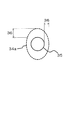
その問題点について、図7A、図7Bを用いて説明する。図7Aは、磁性薄帯1を積層して構成された固定子33aの上面図である。図7Bは、固定子33aの内径部34aと回転子35とが為すエアギャップ36を示す模式図である。
The problem will be described with reference to FIGS. 7A and 7B. FIG. 7A is a top view of the
図7A、図7Bに示すように、磁性薄帯1を積層した場合、固定子の内径部34は楕円形状となる。これにより、図7Bに示すように、固定子33aの内径部34aと回転子35とが為すエアギャップ36のばらつきが大きくなる。その結果、コギングトルクが大きくなってしまう。
As shown in FIGS. 7A and 7B, when the
本開示の一態様の目的は、コギングトルクを低減できる固定子およびモータを提供することである。 An object of one aspect of the present disclosure is to provide a stator and a motor capable of reducing cogging torque.
本開示の一態様に係る固定子は、複数のティース部を備えた磁性薄帯が複数積層された固定子であって、前記磁性薄帯は、前記複数のティース部の先端部分に沿って形成された楕円形状の内径部を有し、積層された前記磁性薄帯のうち、少なくとも1つの磁性薄帯が、他の磁性薄帯に対して水平方向に所定角度ずれており、かつ、積層された前記磁性薄帯の全ての前記ティース部の位置が一致している。 The stator according to one aspect of the present disclosure is a stator in which a plurality of magnetic strips having a plurality of tooth portions are laminated, and the magnetic strips are formed along the tip portions of the plurality of teeth portions. At least one of the laminated magnetic strips having an elliptical inner diameter portion is displaced by a predetermined angle in the horizontal direction with respect to the other magnetic strips, and the magnetic strips are laminated. The positions of all the teeth portions of the magnetic strip are the same.
本開示の一態様に係るモータは、本開示の一態様に係る固定子と、回転子と、を含む。 The motor according to one aspect of the present disclosure includes a stator and a rotor according to one aspect of the present disclosure.
本開示によれば、コギングトルクを低減できる。 According to the present disclosure, the cogging torque can be reduced.
以下、本開示の実施の形態について、図面を参照しながら説明する。なお、各図において共通する構成要素については同一の符号を付し、それらの説明は適宜省略する。 Hereinafter, embodiments of the present disclosure will be described with reference to the drawings. The components common to each figure are designated by the same reference numerals, and their description will be omitted as appropriate.
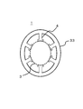
まず、図1を用いて、本実施の形態に係る磁性薄帯1について説明する。図1は、本実施の形態の磁性薄帯1の上面図である。
First, the
図1に示す磁性薄帯1は、例えば、非晶質磁性体の薄帯(非晶質薄帯といってもよい)である。磁性薄帯1は、例えば、溶融状態の金属を約1000000℃/秒程度の超高速で急冷する液体急冷凝固法により製造される。
The
磁性薄帯1の1枚あたりの厚みを概ね0.01mmより小さくすると、液体急冷凝固法によって磁性薄帯1に穴が空き、モータ100(図2参照)の効率が低下する。一方、磁性薄帯1の1枚あたりの厚みを概ね0.06mmより大きくすると、磁気特性が低下するため、モータ100の効率が低下する。よって、磁性薄帯1の1枚あたりの厚みは、概ね0.01乃至0.06mmであることが好ましい。
When the thickness of each
図1に示すように、磁性薄帯1は、その内側に突起状のティース部4を有している。なお、図1では、ティース部4の数が5つである場合を例示しているが、これに限定されない。
As shown in FIG. 1, the
また、図1に示すように、磁性薄帯1の内径部3は、各ティース部4の先端部に沿って形成されており、楕円形状である。
Further, as shown in FIG. 1, the
以上説明した磁性薄帯1は、後述するモータ100の固定子7に用いられる。
The
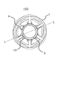
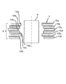
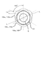
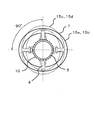
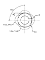
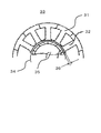
次に、図2〜図4を用いて、本実施の形態に係るモータ100について説明する。図2は、本実施の形態のモータ100の上面図である。図3は、図1に示した点線L−Lの断面拡大図である。図4は、小積層体それぞれの内径部およびエアギャップの一例を模式的に示す上面図である。
Next, the
モータ100は、固定子7と、固定子7により回転される回転子5とを有する。
The
図2に示すように、回転子5は、固定子7における各ティース部4の内側に設けられる。
As shown in FIG. 2, the
固定子7は、図1に示した磁性薄帯1を複数積層した積層体2(図3参照)を有する。
The
また、図2に示すように、固定子7の内径部3は、各ティース部4の先端部に沿って形成されている。なお、図2では、ティース部4に巻回されるコイルの図示を省略している。
Further, as shown in FIG. 2, the
図3に示すように、積層体2は、小積層体15a〜15fを含む。
As shown in FIG. 3, the
小積層体15a〜15fは、それぞれ、複数の磁性薄帯1を円周方向にずらさずに積層させたものである。小積層体15a〜15fそれぞれの厚みは、概ね0.06mm乃至5mmである。
Each of the small
なお、本実施の形態において「円周方向」とは、各上面図において時計回りの方向または反時計回りの方向をいう。また、円周方向は、水平方向の一例である。 In the present embodiment, the "circumferential direction" means a clockwise direction or a counterclockwise direction in each top view. The circumferential direction is an example of the horizontal direction.
このような小積層体15a〜15fを、全てのティース部4の位置を一致させ、かつ、円周方向に所定角度回転させて(換言すれば、所定角度水平回転させて)積層させる。所定角度は、例えば、120°である。これにより、例えば、小積層体15c、15d(内径部16c、16d)は、小積層体15a、15b(内径部16a、16b)に対して円周方向に120°ずれ、小積層体15e、15f(内径部16e、16f)は、小積層体15c、15d(内径部16c、16d)に対して円周方向に120°ずれる(図4参照)。
Such small
図3、図4に示す内径部16a〜16fは、それぞれ、上述したように積層された小積層体15a〜15fの内径部である。内径部16a〜16fは、それぞれ、設計上の内径部φ60mmに対して、概ねφ59.5mm乃至φ60.5mmの範囲である。
The
上述したように小積層体15a〜15fを円周方向にずらして積層することにより、図4に示すように、エアギャップ14を、小積層体15a〜15fの積層方向(固定子7の厚さ方向といってもよい)および固定子7の円周方向全体において平均化することができる。エアギャップ14は、固定子7の内径部10と回転子5との間の距離である。
By laminating the
以上説明したように、本実施の形態の固定子7では、エアギャップ14の円周方向のばらつきと積層方向のばらつきを平均化できるので、全体としてエアギャップ14を小さくすることができる。従来のモータでは、定格トルクの1.5%乃至2.0%の範囲で発生していたコギングトルクを、本実施の形態の固定子7を備えたモータ100では、定格トルクの0.2%乃至0.7%にまで低減することができた。
As described above, in the
なお、小積層体15a〜15fそれぞれの厚みを小さくするほど、小積層体15a〜15fの積層方向に対するエアギャップ14のばらつきを均等にでき、コギングトルクをより小さくすることができる。ただし、小積層体15a〜15fそれぞれの厚みを概ね0.06mmよりも小さくすると、小積層体15a〜15fの剛性が低くなる。その結果、ティース部4の先端部が変形したり、モータ100の効率が低下したりしてしまう。その一方で、小積層体15a〜15fそれぞれの厚みを概ね5mmより大きくすると、小積層体15a〜15fの積層方向に対するエアギャップ14の局所的な偏りが無視できなくなり、コギングトルクを悪化させる。以上のことから、小積層体15a〜15fそれぞれの厚みは、概ね0.06mm乃至5mmであることが好ましい。
As the thickness of each of the small
また、小積層体15a〜15fを円周方向に回転させる角度(以下、回転角度という)は、隣り合うティース部4の為す角度(例えば、図4に示す60°)の整数倍であることが好ましい。例えば、図2に示したようにティース部4の数が6個である場合、回転角度を120°とする。なお、ティース部4の数が6個以外である場合でも、回転角度を隣り合うティース部4の為す角度の整数倍とすることにより、エアギャップ14のばらつきを小さくすることができ、コギングトルクを低減できる。
Further, the angle at which the small
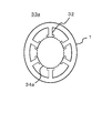
ここで、例えば固定子7におけるティース部4の数が4個である場合について、図5A、図5Bを用いて説明する。図5Aは、固定子5および回転子7の上面図である。図5Bは、小積層体15a〜15dそれぞれの内径部16a〜16dおよびエアギャップ14の一例を模式的に示す上面図である。
Here, for example, a case where the number of
図5Aに示すように、固定子7は、4個のティース部4を有する。隣り合うティース部4の為す角度は、90°である。また、固定子7は、積層された小積層体15a〜15dを含む。
As shown in FIG. 5A, the
図5Aに示すように、小積層体15a、15bは、小積層体15c、15dに対し、円周方向に90°回転している。これにより、例えば、小積層体15a、15bは、小積層体15c、15dに対して円周方向に90°ずれる。すなわち、この場合では、隣り合うティース部4の為す角度と、回転角度とが同じである。
As shown in FIG. 5A, the small
この場合でも、図5Bに示すように、エアギャップ14を、小積層体15a〜15dの積層方向(固定子7の厚さ方向といってもよい)および固定子7の円周方向全体において平均化することができる。
Even in this case, as shown in FIG. 5B, the
したがって、固定子7のティース部4が4個である場合でも、エアギャップ14のばらつきを小さくする(換言すれば、平均化する)ことができ、コギングトルクを低減することができる。
Therefore, even when the
以下、エアギャップ14のばらつきを小さくでき、コギングトルクを低減できた理由について説明する。
Hereinafter, the reason why the variation of the
図1に示した磁性薄帯1は、非晶質薄帯であり、Fe(鉄)系磁性材料料を用いて液体急冷凝固法により製造される。液体急冷凝固法では、超高速で非晶質薄帯を巻き取る必要がある。そのため、液体急冷凝固法では、ある一定幅の状態の磁性材料に対して液体を供給しつつ、水冷された銅ロールに磁性材料を連続的に巻きつけては、非晶質薄帯を銅ロールから引き剥がすという工程が採用されている。
The
磁性材料は、急冷されて凝固する時に(換言すれば、非晶質へ相変態する時に)、銅ロールに巻きついた状態となる。このとき、磁性材料は、その流れ方向(銅ロールの円周方向)において、銅ロールの曲率に保たれる。よって、磁性材料内には、歪みが蓄積される。一方、磁性材料は、その幅方向において、銅ロールの曲率の影響を受けることはない。 When the magnetic material is rapidly cooled and solidified (in other words, when it undergoes a phase transformation to amorphous), it is wrapped around a copper roll. At this time, the magnetic material is maintained at the curvature of the copper roll in the flow direction (circumferential direction of the copper roll). Therefore, strain is accumulated in the magnetic material. On the other hand, the magnetic material is not affected by the curvature of the copper roll in the width direction.
その結果、磁性材料は、その幅方向と流れ方向とにおいて、蓄積される歪み量が大きく異なるという特徴がある。 As a result, the magnetic material is characterized in that the amount of strain accumulated is significantly different in the width direction and the flow direction.
この磁性材料を図1に示した磁性薄帯1の形状に加工すると、磁性材料内の莫大な歪みがある程度開放されるため、加工後の形状には変形が生じる。しかし、上述したとおり、磁性材料の幅方向と流れ方向とにおいて歪み量が異なるため、結果的には、図1に示したように、内径部3が楕円形状の磁性薄帯1が形成される。
When this magnetic material is processed into the shape of the
よって、磁性薄帯1を積層して形成された小積層体15a〜15fの内径部16a〜16f(図4参照)も楕円形状となる。
Therefore, the
本実施の形態では、このような小積層体15a〜15fを、全てのティース部4の位置を一致させ、かつ、円周方向に所定角度回転させて積層させることにより、固定子7を作製する。この固定子7では、図4に示したように、エアギャップ14を、固定子7(積層体2でもよい)の円周方向および固定子7(積層体2でもよい)の厚み方向において平均化することができる。
In the present embodiment, the
このようにエアギャップ14を平均化することにより、モータ100の回転動作時に回転子5から固定子7に入る磁束密度のばらつきを小さくすることができる。その結果、コギングトルクを低減することができる。
By averaging the
なお、本開示は、上記実施の形態の説明に限定されず、その趣旨を逸脱しない範囲において種々の変形が可能である。 The present disclosure is not limited to the description of the above embodiment, and various modifications can be made without departing from the spirit of the present embodiment.
例えば、実施の形態では、磁性薄帯1が非晶質薄帯である場合を例に挙げて説明したが、磁性薄帯1は、ナノ結晶粒を有する磁性体の薄帯(以下、ナノ結晶薄帯という)であってもよい。このナノ結晶薄帯は、一般的に、非晶質薄帯に対して一定の熱処理を与えた場合にのみ生成できる結晶状態の薄帯である。そのため、ナノ結晶薄帯は、非晶質薄帯と同様に、楕円形状の内径部を有する形状となる。したがって、ナノ結晶薄帯を用いて形成された小積層体の内径部も楕円形状となる。そして、その小積層体を円周方向に回転させて積層した固定子、および、その固定子を備えたモータは、エアギャップのばらつきを平均化することができる。よって、その結果、コギングトルクを低減することができる。
For example, in the embodiment, the case where the
本開示の固定子およびモータは、インナーロータ方式またはアウターロータ方式のモータなど様々な構造のモータに適用することが可能である。また、本開示の固定子は、トランスおよびパワーチョークコイル等の磁気を応用した電子部品の用途にも適用できる。 The stator and motor of the present disclosure can be applied to a motor having various structures such as an inner rotor type motor or an outer rotor type motor. The stator of the present disclosure can also be applied to applications of electronic components to which magnetism is applied, such as transformers and power choke coils.
1 磁性薄帯
2 積層体
3 磁性薄帯の内径部
4、32 ティース部
5、35 回転子
7、33、33a 固定子
10、34、34a 固定子の内径部
14、36 エアギャップ
15a、15b、15c、15d、15e、15f 小積層体
16a、16b、16c、16d、16e、16f 小積層体の内径部
31 電磁鋼板
1
Claims (7)
前記磁性薄帯は、
前記複数のティース部の先端部分に沿って形成された楕円形状の内径部を有し、
積層された前記磁性薄帯のうち、少なくとも1つの磁性薄帯が、他の磁性薄帯に対して水平方向に所定角度ずれており、かつ、積層された前記磁性薄帯の全ての前記ティース部の位置が一致している、
固定子。 It is a stator in which a plurality of magnetic strips having a plurality of teeth parts are laminated.
The magnetic strip is
It has an elliptical inner diameter portion formed along the tip portions of the plurality of teeth portions, and has an elliptical inner diameter portion.
At least one of the laminated magnetic strips is displaced by a predetermined angle in the horizontal direction with respect to the other magnetic strips, and all the teeth portions of the laminated magnetic strips. Positions match,
stator.
前記複数の小積層体のうち、少なくとも1つの小積層体が、他の小積層体に対して水平方向に所定角度ずれており、かつ、積層された前記磁性薄帯の全ての前記ティース部の位置が一致している、
請求項1に記載の固定子。 The laminated magnetic strips are divided into a plurality of small laminates in which the magnetic strips are laminated in the horizontal direction without shifting the predetermined angle.
At least one of the plurality of small laminates is displaced by a predetermined angle in the horizontal direction with respect to the other small laminates, and all the teeth portions of the laminated magnetic strips The positions match,
The stator according to claim 1.
請求項2に記載の固定子。 The thickness of each small laminate is 0.06 mm or more.
The stator according to claim 2.
請求項1から3のいずれか1項に記載の固定子。 The predetermined angle is an angle formed by the teeth portions adjacent to each other, or an angle obtained by an integral multiple of the angle formed by the teeth portions adjacent to each other.
The stator according to any one of claims 1 to 3.
請求項1から4のいずれか1項に記載の固定子。 The magnetic strip is an amorphous strip or a nanocrystalline strip,
The stator according to any one of claims 1 to 4.
請求項1から5のいずれか1項に記載の固定子。 The thickness of each of the magnetic strips is 0.01 to 0.06 mm.
The stator according to any one of claims 1 to 5.
回転子と、を含む、
モータ。 The stator according to any one of claims 1 to 6 and the stator.
Including the rotor,
motor.
Priority Applications (3)
| Application Number | Priority Date | Filing Date | Title |
|---|---|---|---|
| JP2019088270A JP7209260B2 (en) | 2019-05-08 | 2019-05-08 | stator and motor |
| US16/836,950 US11601021B2 (en) | 2019-05-08 | 2020-04-01 | Stator and motor |
| CN202010252648.3A CN111917198B (en) | 2019-05-08 | 2020-04-01 | Stator and motor |
Applications Claiming Priority (1)
| Application Number | Priority Date | Filing Date | Title |
|---|---|---|---|
| JP2019088270A JP7209260B2 (en) | 2019-05-08 | 2019-05-08 | stator and motor |
Publications (2)
| Publication Number | Publication Date |
|---|---|
| JP2020184836A true JP2020184836A (en) | 2020-11-12 |
| JP7209260B2 JP7209260B2 (en) | 2023-01-20 |
Family
ID=73045578
Family Applications (1)
| Application Number | Title | Priority Date | Filing Date |
|---|---|---|---|
| JP2019088270A Active JP7209260B2 (en) | 2019-05-08 | 2019-05-08 | stator and motor |
Country Status (3)
| Country | Link |
|---|---|
| US (1) | US11601021B2 (en) |
| JP (1) | JP7209260B2 (en) |
| CN (1) | CN111917198B (en) |
Cited By (2)
| Publication number | Priority date | Publication date | Assignee | Title |
|---|---|---|---|---|
| JPWO2023139637A1 (en) * | 2022-01-18 | 2023-07-27 | ||
| JP2024122001A (en) * | 2023-02-28 | 2024-09-09 | トヨタ自動車株式会社 | Rotating Machine |
Families Citing this family (1)
| Publication number | Priority date | Publication date | Assignee | Title |
|---|---|---|---|---|
| EP3785329A4 (en) * | 2018-04-25 | 2022-01-12 | PPC Broadband, Inc. | Coaxial cable connectors having port grounding |
Citations (3)
| Publication number | Priority date | Publication date | Assignee | Title |
|---|---|---|---|---|
| JP2007174827A (en) * | 2005-12-22 | 2007-07-05 | Nissan Motor Co Ltd | Electric motor stator structure |
| JP2009112096A (en) * | 2007-10-29 | 2009-05-21 | Toyota Industries Corp | Stator core fixing method and electric compressor |
| JP2018093704A (en) * | 2016-12-06 | 2018-06-14 | パナソニック株式会社 | Iron core and motor |
Family Cites Families (18)
| Publication number | Priority date | Publication date | Assignee | Title |
|---|---|---|---|---|
| US5334894A (en) * | 1991-05-14 | 1994-08-02 | Shinko Electric Co., Ltd. | Rotary pulse motor |
| JP3678102B2 (en) | 2000-02-02 | 2005-08-03 | 株式会社日立製作所 | Electric motor |
| JP2003304655A (en) * | 2002-04-10 | 2003-10-24 | Nippon Steel Corp | Stator core structure of rotating electric machine |
| JP3938726B2 (en) * | 2002-07-12 | 2007-06-27 | 株式会社日立産機システム | Permanent magnet type rotating electric machine and compressor using the same |
| CN101375484A (en) * | 2006-01-24 | 2009-02-25 | 株式会社安川电机 | Split core for motor stator, permanent magnet synchronous motor, and punching method using split core punching die |
| WO2008044740A1 (en) * | 2006-10-13 | 2008-04-17 | Mitsui High-Tec, Inc. | Laminated iron core, and its manufacturing method |
| JP5171224B2 (en) * | 2007-11-22 | 2013-03-27 | 三菱電機株式会社 | Rotating electric machine |
| CN102035277B (en) * | 2009-10-07 | 2014-08-20 | 阿斯莫有限公司 | Motor |
| US9601950B2 (en) * | 2011-05-26 | 2017-03-21 | Mitsubishi Electric Corporation | Permanent magnet motor |
| US8963396B2 (en) * | 2011-09-26 | 2015-02-24 | Pangolin Laser Systems, Inc. | Electromechanical device and assembly method |
| US9270144B2 (en) * | 2011-09-26 | 2016-02-23 | William R. Benner, Jr. | High torque low inductance rotary actuator |
| JP5844205B2 (en) | 2012-04-10 | 2016-01-13 | 住友重機械工業株式会社 | Stator core and rotary electric motor using the same |
| US9106122B2 (en) * | 2013-01-25 | 2015-08-11 | Everette Energy, LLC | Single phase switched reluctance machine with short flux path |
| WO2017090571A1 (en) * | 2015-11-27 | 2017-06-01 | 日本電産株式会社 | Motor and method for manufacturing motor |
| CN108155730B (en) * | 2016-12-06 | 2022-02-25 | 松下电器产业株式会社 | Iron core and motor |
| JP6586436B2 (en) * | 2017-04-25 | 2019-10-02 | 東芝三菱電機産業システム株式会社 | Rotating electric machine and its rotor |
| CN110637408B (en) * | 2017-05-23 | 2022-11-15 | 三键有限公司 | Laminated steel sheet, method for producing same, engine, and adhesive composition for laminated steel sheet |
| CN108390478A (en) * | 2018-05-31 | 2018-08-10 | 广东美芝制冷设备有限公司 | Stator core, Stator and electrical machine |
-
2019
- 2019-05-08 JP JP2019088270A patent/JP7209260B2/en active Active
-
2020
- 2020-04-01 US US16/836,950 patent/US11601021B2/en active Active
- 2020-04-01 CN CN202010252648.3A patent/CN111917198B/en active Active
Patent Citations (3)
| Publication number | Priority date | Publication date | Assignee | Title |
|---|---|---|---|---|
| JP2007174827A (en) * | 2005-12-22 | 2007-07-05 | Nissan Motor Co Ltd | Electric motor stator structure |
| JP2009112096A (en) * | 2007-10-29 | 2009-05-21 | Toyota Industries Corp | Stator core fixing method and electric compressor |
| JP2018093704A (en) * | 2016-12-06 | 2018-06-14 | パナソニック株式会社 | Iron core and motor |
Cited By (4)
| Publication number | Priority date | Publication date | Assignee | Title |
|---|---|---|---|---|
| JPWO2023139637A1 (en) * | 2022-01-18 | 2023-07-27 | ||
| WO2023139637A1 (en) * | 2022-01-18 | 2023-07-27 | 三菱電機株式会社 | Rotary compressor |
| JP7584682B2 (en) | 2022-01-18 | 2024-11-15 | 三菱電機株式会社 | Rotary Compressor |
| JP2024122001A (en) * | 2023-02-28 | 2024-09-09 | トヨタ自動車株式会社 | Rotating Machine |
Also Published As
| Publication number | Publication date |
|---|---|
| CN111917198A (en) | 2020-11-10 |
| CN111917198B (en) | 2024-07-12 |
| JP7209260B2 (en) | 2023-01-20 |
| US20200358323A1 (en) | 2020-11-12 |
| US11601021B2 (en) | 2023-03-07 |
Similar Documents
| Publication | Publication Date | Title |
|---|---|---|
| JP5186036B2 (en) | IPM motor rotor and IPM motor using the same | |
| JP4840215B2 (en) | Permanent magnet type rotating electric machine and compressor using the same | |
| JP5859297B2 (en) | Rotating electric machine | |
| JP5181827B2 (en) | Axial gap motor and fan device using the same | |
| JP2008245440A (en) | Induction machine | |
| JP7209260B2 (en) | stator and motor | |
| JP2008245346A (en) | Commutator motor and electric vacuum cleaner using the same | |
| JPWO2014102950A1 (en) | Rotating electric machine | |
| JP2011174103A (en) | Magnetic material for iron core, method for producing the same, and iron core | |
| JP2005304177A (en) | End plates used for motors and rotors of motors | |
| JP2010045870A (en) | Rotating machine | |
| JP2001303213A (en) | Non-oriented electrical steel sheet for high efficiency motors | |
| JP6069475B2 (en) | Rotating electric machine | |
| TWI552486B (en) | Axial air gap motor | |
| JP2010263714A (en) | Motor core and method for manufacturing the same | |
| JP2020072626A (en) | Stator core of rotary electric machine | |
| JP2003264946A (en) | Motor stator core | |
| JP2010068548A (en) | Motor | |
| JP2001025181A (en) | Stator core material and motor mounted with the same | |
| JP2005354806A (en) | Rotor for electric motor and method for manufacturing rotor for electric motor | |
| JP5120019B2 (en) | Stator core for electric motor | |
| JP2020178411A (en) | Stator core and motor | |
| JP5152957B2 (en) | Stator core and motor stator and motor | |
| JP5445003B2 (en) | Stator core for electric motor | |
| JP2017099149A (en) | Rotating electric machine, iron core of rotating electric machine, and manufacturing method of iron core of rotating electric machine |
Legal Events
| Date | Code | Title | Description |
|---|---|---|---|
| RD02 | Notification of acceptance of power of attorney |
Free format text: JAPANESE INTERMEDIATE CODE: A7422 Effective date: 20190625 |
|
| RD04 | Notification of resignation of power of attorney |
Free format text: JAPANESE INTERMEDIATE CODE: A7424 Effective date: 20191021 |
|
| A621 | Written request for application examination |
Free format text: JAPANESE INTERMEDIATE CODE: A621 Effective date: 20211214 |
|
| A977 | Report on retrieval |
Free format text: JAPANESE INTERMEDIATE CODE: A971007 Effective date: 20220922 |
|
| A131 | Notification of reasons for refusal |
Free format text: JAPANESE INTERMEDIATE CODE: A131 Effective date: 20220927 |
|
| A521 | Request for written amendment filed |
Free format text: JAPANESE INTERMEDIATE CODE: A523 Effective date: 20221014 |
|
| TRDD | Decision of grant or rejection written | ||
| A01 | Written decision to grant a patent or to grant a registration (utility model) |
Free format text: JAPANESE INTERMEDIATE CODE: A01 Effective date: 20221206 |
|
| A61 | First payment of annual fees (during grant procedure) |
Free format text: JAPANESE INTERMEDIATE CODE: A61 Effective date: 20221223 |
|
| R151 | Written notification of patent or utility model registration |
Ref document number: 7209260 Country of ref document: JP Free format text: JAPANESE INTERMEDIATE CODE: R151 |