JP2020044569A - Box-bending punch die and box-bending punch die set - Google Patents
Box-bending punch die and box-bending punch die set Download PDFInfo
- Publication number
- JP2020044569A JP2020044569A JP2018176981A JP2018176981A JP2020044569A JP 2020044569 A JP2020044569 A JP 2020044569A JP 2018176981 A JP2018176981 A JP 2018176981A JP 2018176981 A JP2018176981 A JP 2018176981A JP 2020044569 A JP2020044569 A JP 2020044569A
- Authority
- JP
- Japan
- Prior art keywords
- punch
- die
- bending
- mold
- pair
- Prior art date
- Legal status (The legal status is an assumption and is not a legal conclusion. Google has not performed a legal analysis and makes no representation as to the accuracy of the status listed.)
- Granted
Links
Images


Abstract
Description
本発明は、板状のワーク(板金)の箱曲げ加工を行うための箱曲げ用パンチ金型及び箱曲げ用金型セットに関する。 The present invention relates to a box bending punch die and a box bending die set for performing box bending of a plate-shaped work (sheet metal).
従来から、ワークの箱曲げ加工を行って箱製品を製作する際には、専用金型として箱曲げ用パンチ金型が用いられている(特許文献1参照)。そして、従来の箱曲げ用パンチ金型の構成について簡単に説明すると、次の通りである。 2. Description of the Related Art Conventionally, when a box product is manufactured by performing a box bending process on a work, a punching die for box bending is used as a dedicated die (see Patent Document 1). The configuration of the conventional box bending punch mold will be briefly described as follows.
箱曲げ用パンチ金型は、プレスブレーキの上部テーブルの下端部に着脱可能に設けられたパンチ金型本体(特許文献1では上型本体)を備えており、パンチ金型本体は、金型長さ方向に延びている。パンチ金型本体の下部には、一対の移動パンチ(特許文献1では隅金型)が金型長さ方向へ移動可能に設けられており、各移動パンチは、ワークを上方向から押圧する押圧部を有している。また、パンチ金型本体の下部における一対の移動パンチの間には、複数の中間パンチ(特許文献1では中間ブロック)が設けられており、各中間パンチは、ワークを上方向から押圧する押圧部を有している。曲げ加工に使用する複数の中間パンチは、ワークの曲げ長さに応じて選択可能である。 The box bending punch includes a punch die main body (an upper die main body in Patent Document 1) detachably provided at a lower end portion of an upper table of a press brake, and the punch die main body has a die length. Extending in the vertical direction. A pair of movable punches (corner molds in Patent Literature 1) are provided at the lower part of the punch die body so as to be movable in the length direction of the die, and each movable punch presses the work from above. Part. A plurality of intermediate punches (intermediate blocks in Patent Document 1) are provided between the pair of moving punches in the lower part of the punch die body, and each intermediate punch presses a work from above. have. A plurality of intermediate punches used for bending can be selected according to the bending length of the work.
各移動金型の金型長さ方向外側には、ヒンジピン(特許文献1ではピン)が金型幅方向に沿って設けられている。換言すれば、パンチ金型本体の下部には、一対のヒンジピンが一対の移動金型を介して設けられている。また、各ヒンジピンには、回転パンチ(引用文献1では回転型)が回転可能に設けられており、各回転パンチは、ワークを上方向から押圧する押圧部を有している。 A hinge pin (a pin in Patent Literature 1) is provided outside the moving mold in the mold length direction along the mold width direction. In other words, a pair of hinge pins are provided at a lower portion of the punch mold body via a pair of movable molds. In addition, a rotary punch (rotary type in Patent Document 1) is rotatably provided on each hinge pin, and each rotary punch has a pressing portion that presses the work from above.
各回転パンチは、その回転によって水平姿勢と傾斜姿勢とに切り替わるように構成されている。水平姿勢とは、回転パンチの押圧部が水平になる姿勢のことである。傾斜姿勢とは、回転パンチの押圧部における金型長さ方向外側が金型長さ方向内側よりも低くなるように、回転パンチの押圧部が水平方向に対して傾斜した姿勢のことである。また、各回転パンチは、ワークの曲げ加工後に上部テーブルが上昇すると、自重(各回転パンチの自重)による回転によって水平姿勢から傾斜姿勢に切り替わるように構成されている。これにより、ワークの箱曲げ加工の終了後又は途中に、回転パンチとL字形状の曲げフランジとの干渉を回避しつつ、箱曲げ用パンチ金型を箱製品又はワークから抜くことができる。 Each rotary punch is configured to switch between a horizontal position and an inclined position by its rotation. The horizontal posture is a posture in which the pressing portion of the rotary punch becomes horizontal. The inclined posture is a posture in which the pressing part of the rotary punch is inclined with respect to the horizontal direction such that the outside of the pressing part of the rotary punch in the length direction of the mold is lower than the inside of the pressing part in the length direction of the mold. In addition, each rotary punch is configured to switch from a horizontal position to an inclined position by rotation due to its own weight (self-weight of each rotary punch) when the upper table rises after bending the work. This makes it possible to remove the box-bending punch from the box product or the work while avoiding interference between the rotary punch and the L-shaped bending flange after or during the box bending of the work.
なお、本発明に関連する先行技術として特許文献1の他に、特許文献2に示すものがある。 As prior art related to the present invention, there is a technique disclosed in Patent Document 2 in addition to Patent Document 1.
ところで、近年、短辺側の寸法のより短い箱製品を製作したいという要望が強くなっている。この要望に応えるためには、各回転パンチを水平姿勢に切り替えた状態における一方の回転パンチの金型長さ方向外側の端部から他方の回転パンチの金型長さ方向外側の端部までの距離、換言すれば、一対の回転パンチの最大の端部間距離を短くしなければならない。一方、箱曲げ用パンチ金型から複数の中間パンチを取り除いたとしても、各回転パンチの回転動作の信頼性を確保するために、一対のヒンジピンを金型長さ方向に十分に離隔させる必要がある。その結果、一対の回転パンチの最大の端部間距離を短くすることによって前述の要望に応えることは困難であるという問題がある。 By the way, in recent years, there has been a strong demand for producing a box product having a shorter dimension on the short side. In order to respond to this demand, in the state where each rotary punch is switched to the horizontal position, the distance between the outer end of the other rotary punch in the die length direction and the outer end of the other rotary punch in the die length direction is changed. The distance, in other words, the maximum distance between the ends of the pair of rotary punches, must be reduced. On the other hand, even if a plurality of intermediate punches are removed from the box bending punch die, it is necessary to sufficiently separate the pair of hinge pins in the die length direction in order to ensure the reliability of the rotation operation of each rotary punch. is there. As a result, there is a problem that it is difficult to meet the above-mentioned demand by shortening the maximum distance between the ends of the pair of rotary punches.
そこで、本発明は、各回転パンチの回転動作の信頼性を確保しつつ、一対の回転パンチの最大の端部間距離を短くすることができる、新規な構成からなる箱曲げ用パンチ金型等を提供することを課題とする。 Accordingly, the present invention provides a box bending punch mold and the like having a novel configuration that can shorten the maximum distance between the ends of a pair of rotary punches while securing the reliability of the rotary operation of each rotary punch. The task is to provide
本発明の第1実施態様に係る箱曲げ用パンチ金型は、パンチ金型本体と、パンチ金型本体に金型幅方向に沿って設けられた1つのヒンジピンと、1つの前記ヒンジピンに回転可能に設けられ、金型長さ方向に対称的に配置され、板状のワーク(板金)を上方向から押圧する押圧部を有した一対の回転パンチと、備えている。そして、各回転パンチは、その回転によって、前記押圧部における金型長さ方向外側が金型長さ方向内側よりも低くなるように前記押圧部が水平方向に対して傾斜した傾斜姿勢と、前記押圧部が水平になる水平姿勢とに切り替わるよう構成される。各回転パンチは、ワークの曲げ加工後に自重(各回転パンチの自重)よる回転によって前記水平姿勢から前記傾斜姿勢に切り替わるように構成されている。 The punching die for box bending according to the first embodiment of the present invention includes a punching die main body, one hinge pin provided on the punching die main body along the die width direction, and is rotatable about one hinge pin. And a pair of rotary punches symmetrically arranged in the mold length direction and having a pressing portion for pressing a plate-shaped work (sheet metal) from above. And, each rotating punch, by the rotation thereof, the pressing portion is inclined with respect to the horizontal direction so that the outside in the mold length direction of the pressing portion is lower than the inside of the mold length direction, the inclined posture, The pressing unit is configured to be switched to a horizontal posture in which the pressing unit is horizontal. Each of the rotary punches is configured to switch from the horizontal position to the inclined position by rotation of its own weight (self-weight of each rotary punch) after bending the work.
本発明の第1実施態様では、各回転パンチの前記押圧部は、平坦面状であってもよい。また、各回転パンチは、前記押圧部を有したパンチボディと、前記パンチボディの金型長さ方向内側に形成され、1つの前記ヒンジピンに回転可能に連結する連結片と、を有してもよい。この場合に、一対の前記回転パンチの前記連結片が重なるように金型幅方向に位置をずらしてもよい。 In the first embodiment of the present invention, the pressing portion of each rotary punch may have a flat surface shape. Further, each rotary punch may include a punch body having the pressing portion, and a connecting piece formed inside the punch body in the mold length direction and rotatably connected to one hinge pin. Good. In this case, the position may be shifted in the die width direction so that the connecting pieces of the pair of rotary punches overlap.
本発明の第1実施態様では、前記パンチ金型本体に着脱可能に設けられたユニットベースを備え、1つの前記ヒンジピンは、前記ユニットベースに設けられることにより、前記ユニットベースを介して前記パンチ金型本体に設けられており、前記ユニットベース、1つの前記ヒンジピン、及び一対の前記回転パンチは、前記パンチ金型本体に対して着脱可能なパンチユニットを構成してもよい。更に、前記ユニットベースは、前記パンチ金型本体に着脱可能に設けられたベースブロックと、前記ベースブロックの下面に金型幅方向に間隔を置いて形成された一対の支持部材と、を有してもよい。この場合、1つの前記ヒンジピンは、一対の前記支持部材の間に金型幅方向に沿って連結するように設けられている。各回転パンチは、前記押圧部を有したパンチボディと、前記パンチボディの金型長さ方向内側に形成され、1つの前記ヒンジピンに回転可能に連結する連結片と、を有してもよい。この場合に、一対の前記回転パンチの前記連結片が一対の前記支持部材の間において重なるように金型幅方向に位置をずらしてもよい。前記水平姿勢の各回転パンチは、金型長さ方向外側から見ると一対の前記支持部材に整合してもよい。 In the first embodiment of the present invention, a unit base is provided detachably on the punch die body, and one hinge pin is provided on the unit base, so that the punch metal is provided via the unit base. The unit base, the one hinge pin, and the pair of rotary punches provided on the mold body may constitute a punch unit that is detachable from the punch mold body. Further, the unit base includes a base block detachably provided on the punch die body, and a pair of support members formed on a lower surface of the base block at intervals in a die width direction. You may. In this case, one hinge pin is provided between the pair of support members so as to be connected along the die width direction. Each rotary punch may include a punch body having the pressing portion, and a connecting piece formed inside the punch body in a mold length direction and rotatably connected to one hinge pin. In this case, the positions of the connecting pieces of the pair of rotary punches may be shifted in the die width direction such that the connecting pieces overlap between the pair of support members. Each of the rotary punches in the horizontal position may be aligned with the pair of support members when viewed from the outside in the mold length direction.
本発明の第1実施態様によると、前述のように、1つの前記ヒンジピンに一対の前記回転パンチが回転可能に設けられ、一対の前記回転パンチが金型長さ方向に対称的に配置されている。各回転パンチは、その回転によって前記水平姿勢と前記傾斜姿勢とに切り替わるよう構成されている。そのため、各回転パンチの回転動作の信頼性を確保しつつ、一対の回転パンチの最大の端部間距離をに短くすることができる。 According to the first embodiment of the present invention, as described above, the pair of rotary punches are rotatably provided on one hinge pin, and the pair of rotary punches are symmetrically arranged in the mold length direction. I have. Each rotary punch is configured to switch between the horizontal posture and the inclined posture by its rotation. Therefore, the maximum distance between the ends of the pair of rotary punches can be reduced while ensuring the reliability of the rotary operation of each rotary punch.
本発明の第2実施態様に係る箱曲げ用金型セットは、本発明の第1実施態様からなる箱曲げ用パンチ金型と、箱曲げ用ダイ金型とからなり、前記箱曲げ用パンチ金型における各回転パンチの前記押圧部は、平坦面状である。前記箱曲げ用ダイ金型は、上側に板状のワーク(板金)における短辺側の曲げフランジに相当する部分を曲げるための直角状の曲げ部を有したダイ金型本体を備えている。前記箱曲げ用ダイ金型は、前記ダイ金型本体における前記曲げ部の正面側に昇降可能(上下方向へ移動可能)に設けられ、上側にワークを支持しかつ一対の前記回転パンチの前記押圧部と協働してワークを挟持する平坦面状の支持部を有した昇降ブロックと、前記昇降ブロックを上方向へ付勢する付勢部材と、を備えている。 The box bending die set according to the second embodiment of the present invention comprises the box bending punch die according to the first embodiment of the present invention and a box bending die die, and the box bending punch die is provided. The pressing portion of each rotary punch in the mold has a flat surface shape. The box bending die includes a die body having a right-angled bent portion for bending a portion corresponding to a bending flange on a short side of a plate-shaped work (sheet metal) on an upper side. The box-bending die is provided on the front side of the bent portion of the die body so as to be vertically movable (movable in the vertical direction), supports a work on the upper side, and presses the pair of rotary punches. A lifting / lowering block having a flat surface-like supporting portion for holding the work in cooperation with the portion; and a biasing member for biasing the lifting / lowering block upward.
本発明の第2実施態様によると、前述のように、前記箱曲げ用金型セットは本発明の第1実施態様に係る前記箱曲げ用パンチ金型と前記箱曲げ用ダイ金型からなる。そのため、本発明の第2実施態様によると、前述の本発明の第1実施態様による作用と同様の作用を奏する。 According to the second embodiment of the present invention, as described above, the box bending die set includes the box bending punch die and the box bending die die according to the first embodiment of the present invention. Therefore, according to the second embodiment of the present invention, the same operation as the above-described operation of the first embodiment of the present invention is achieved.
本発明によれば、前記箱曲げ用パンチ金型を用いて短辺側の寸法のより短い箱製品を製作することができる。 According to the present invention, a box product having a shorter dimension on the short side can be manufactured using the box bending punch.
以下、本発明の実施形態について図1から図9を参照して説明する。 Hereinafter, an embodiment of the present invention will be described with reference to FIGS.
なお、本願の明細書及び特許請求の範囲において、「設けられる」とは、直接的に設けられることの他に、別部材を介して間接的に設けられることを含む意である。また、「金型長さ方向」とは、箱曲げ用パンチ金型又は箱曲げ用ダイ金型の長さ方向のことをいい、本発明の実施形態にあっては、左右方向のことをいう。
「金型長さ方向外側」とは、金型長さ方向の片側であって箱曲げ用パンチ金型又は箱曲げ用ダイ金型の中心から遠い側(1つのヒンジピンから遠い側)のことをいう。「金型長さ方向内側」とは、金型長さ方向の片側であって箱曲げ用パンチ金型又は箱曲げ用ダイ金型の中心から近い側(1つのヒンジピンから近い側)のことをいう。「金型幅方向」とは、箱曲げ用パンチ金型又は箱曲げ用ダイ金型の幅方向のことをいい、本発明の実施形態にあっては、前後方向のことをいう。
In the specification and claims of the present application, “provided” means to be provided indirectly via another member in addition to being provided directly. Further, the “mold length direction” refers to the length direction of the box bending punch die or the box bending die die, and in the embodiment of the present invention, refers to the left-right direction. .
The term “outside in the mold length direction” refers to one side in the mold length direction that is far from the center of the box bending punch die or box bending die die (the side far from one hinge pin). Say. "Inside the mold length direction" means one side in the mold length direction that is closer to the center of the punching die for box bending or die for box bending (the side closer to one hinge pin). Say. The “mold width direction” refers to the width direction of the box bending punch die or the box bending die die, and in the embodiment of the present invention, refers to the front-back direction.
「水平」とは、完全な水平に限定されず、水平方向に対して僅かに(例えば3度未満程度)傾斜した状態も含む意である。「短辺」とは、隣り合う2つの端辺のうち短い方の端辺のことをいい、隣り合う2つの端辺の長さが同じ場合には、いずれの端辺も含む意である。「長辺」とは、隣り合う2つの端辺のうち長い方の端辺ことをいい、隣り合う2つの端辺の長さが同じ場合には、いずれの端辺も含む意である。 The term “horizontal” is not limited to perfect horizontal, but also includes a state in which it is slightly (eg, less than 3 degrees) inclined with respect to the horizontal direction. The “short side” refers to the shorter one of two adjacent sides, and when the lengths of the two adjacent sides are the same, it is meant to include any one of the two sides. The “long side” refers to the longer one of two adjacent sides, and when the two adjacent sides have the same length, it is meant to include any one of the two sides.
図面中、「CA」は金型長さ方向、「L」は左方向、「R」は右方向、「CB」は金型幅方向、「FF」は前方向、「FR」は後方向、「「U」は上方向、「D」は下方向をそれぞれ指している。 In the drawings, "CA" is a mold length direction, "L" is a left direction, "R" is a right direction, "CB" is a mold width direction, "FF" is a front direction, "FR" is a rear direction, “U” indicates an upward direction, and “D” indicates a downward direction.
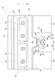
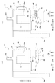
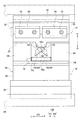
図1及び図2(a)(b)に示すように、本発明の実施形態に係る箱曲げ用金型セット10は、プレスブレーキの上部テーブル12の下端部にパンチホルダ(図示省略)を介して設けられた箱曲げ用パンチ金型14と、プレスブレーキの下部テーブル16の上端部に設けられた箱曲げ用ダイ金型18とからなる。また、箱曲げ用金型セット10は、板状のワーク(板金)Wの箱曲げ加工を行って4つのL字形状の曲げフランジFを有した箱製品Mを製作する際に用いられる。特に、箱曲げ用金型セット10は、ワークWの箱曲げ加工のうち、ワークWにおける短辺側の曲げフランジに相当する部分F’の曲げ加工を行う際に用いられる。 As shown in FIGS. 1 and 2A and 2B, the box bending mold set 10 according to the embodiment of the present invention includes a punch holder (not shown) provided at the lower end of the upper table 12 of the press brake. And a box bending die 14 provided at the upper end of the lower table 16 of the press brake. The box bending die set 10 is used when a box-shaped workpiece (sheet metal) W is subjected to box bending to produce a box product M having four L-shaped bent flanges F. In particular, the box bending mold set 10 is used when performing bending of a portion F ′ corresponding to a bending flange on the short side of the work W in box bending of the work W.
なお、ワークWの箱曲げ加工のうち、ワークWにおける長辺側の曲げフランジに相当する部分F’の曲げ加工は、ワークWにおける短辺側の曲げフランジに相当する部分F’の曲げ加工を行う前に、汎用の金型セット(図示省略)を用いて行われる。図2(b)には、破線で曲げ線を示しており、各曲げ線に付した番号は、曲げ加工の順番を一例として示している。 In the box bending of the workpiece W, the bending of the portion F ′ corresponding to the bending flange on the long side of the workpiece W is performed by bending the portion F ′ of the workpiece W corresponding to the bending flange on the short side. Before performing the process, the process is performed using a general-purpose mold set (not shown). In FIG. 2B, the bending lines are indicated by broken lines, and the numbers assigned to the respective bending lines indicate the order of the bending as an example.
続いて、本発明の実施形態に係る箱曲げ用パンチ金型14の具体的な構成について図1から図5(a)(b)を参照して説明する。 Next, a specific configuration of the box bending punch die 14 according to the embodiment of the present invention will be described with reference to FIGS. 1 to 5A and 5B.
箱曲げ用パンチ金型14は、金型長さ方向に延びたパンチ金型本体20を備えている。パンチ金型本体20の上部には、上部テーブル12の下端部にパンチホルダを介して取付けるためシャンク部22が形成されている。パンチ金型本体20の正面側の下部には、段部(段状の凹部)20dが形成されている。
The box bending punch die 14 includes a punch die
図1から図5(a)(b)に示すように、パンチ金型本体20の段部20dには、金型長さ方向に延びたユニットベース24が着脱可能に設けられている。パンチ金型本体20の下面には、ユニットベース24を下方向から支持する支持プレート26が複数の取付ボルト(図示省略)を介して設けられている。パンチ金型本体20の正面(前面)には、ユニットベース24を前方向から押さえる複数の押え具28が複数の取付ボルト30を介して設けられている。パンチ金型本体20の左側面には、ユニットベース24の金型長さ方向の位置を規定するための規定板32が複数の取付ボルト(図示省略)を介して設けられている。
As shown in FIGS. 1 to 5A and 5B, a
ユニットベース24は、パンチ金型本体20の段部20dに着脱可能に設けられたベースブロック34を有しており、ベースブロック34は、金型長さ方向に延びている。ベースブロック34の下面の中央には、矩形状の凸部36が形成されている。また、ベースブロック34の凸部36の前部には、一方の支持部材としての支持片38が形成されている。支持片38は、その下側に、ワークWを上方向から押圧する平坦面状の押圧部38pを有している。支持片38の押圧部38pは、前側が後側よりも僅かに高くなるように水平方向に対して僅かに(例えば1度)傾斜しているが、水平方向に対して傾斜させなくてもよい。
The
ベースブロック34の凸部36の後部には、他方の支持部材としての支持爪40が支持片38と金型幅方向に間隔を置いて形成されている。支持爪40は、その下側に、ワークWを上方向から押圧する平坦面状の押圧部40pを有している。支持爪40の押圧部40pは、支持片38の押圧部38pと同一平面上に位置している。支持爪40の後部には、ワークW又は箱製品Mにおける短辺側のL字形状の曲げフランジFとの干渉を回避するためのバック傾斜面40bが形成されている(図5(b)参照)。
At the rear of the
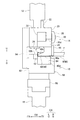
ユニットベース24における支持片38と支持爪40との間に、1つのヒンジピン42が金型幅方向に沿って連結するように設けられている。換言すれば、パンチ金型本体20の下面の中央部には、1つのヒンジピン42がユニットベース24を介して金型幅方向に沿って設けられている。また、ユニットベース24の凸部36の正面には、支持片38からの1つのヒンジピン42の離脱を防止するための止め板44が複数の取付ボルト(図示省略)を介して設けられている。
One
1つのヒンジピン42には、一対の回転パンチ46が回転可能に設けられており、一対の回転パンチ46は、金型長さ方向に対称に配置されている。また、各回転パンチ46は、ワークWを上方向から押圧する平坦面状の押圧部48pを有したパンチボディ48と、パンチボディ48の金型長さ方向内側に形成されかつ1つのヒンジピン42に回転可能に連結する連結片50とを有している。一対の回転パンチ46の連結片50は、支持片38と支持爪40の間において重なるように金型幅方向に位置をずらしている(図3A参照)。一対の回転パンチ46の連結片50の厚み(金型幅方向の長さ)の合計寸法は、支持片38と支持爪40との間隔寸法よりも僅かに小さく設定されている。各パンチボディ48の後部には、ワークW又は箱製品Mにおける短辺側のL字形状の曲げフランジFとの干渉を回避するためのバック傾斜面48bが形成されている(図8参照)。各パンチボディ48の金型長さ方向外側の側部には、ワークW又は箱製品Mにおける長辺側のL字形状の曲げフランジFとの干渉を回避するためのサイド傾斜面48sが形成されている(図7参照)。
A pair of
図3Aから図5(a)(b)に示すように、各回転パンチ46は、その回転によって水平姿勢と傾斜姿勢とに切り替わるように構成されている。水平姿勢とは、パンチボディ48の押圧部48pが水平になる姿勢のことをいう。傾斜姿勢とは、パンチボディ48の押圧部48pにおける金型長さ方向外側が金型長さ方向内側よりも低くなるように、パンチボディ48の押圧部48pが水平方向に対して傾斜した姿勢のことをいう。また、各回転パンチ46は、ワークWの曲げ加工後に上部テーブル12が上昇すると、自重(各回転パンチ46の自重)による回転によって水平姿勢から傾斜姿勢に切り替わるように構成されている(図9参照)。
As shown in FIGS. 3A to 5A and 5B, each
各連結片50には、各回転パンチ46の自重による回転を規制するためのストッパ面50sが形成されている(図4B参照)。各連結片50のストッパ面50sは、各回転パンチ46がワークWと非接触状態のときに、各回転パンチ46の自重によってベースブロック34の凸部36の下面に当接する。換言すれば、各回転パンチ46は、ワークWと非接触状態のときに、傾斜姿勢に保持されるように構成されている。また、水平姿勢の各回転パンチ46は、金型長さ方向外側から見ると支持片38と支持爪40に整合している(図5(a)参照)。換言すれば、水平姿勢の各パンチボディ48の押圧部48pは、支持片38の押圧部38p及び支持爪40の押圧部40pと同一平面上に位置している。更に、ベースブロック34の凸部36における1つのヒンジピン42の両側には、水平姿勢の回転パンチ46を下方向へ押圧するボールプランジャ52がそれぞれ設けられている(図4A及び図4B参照)。
Each connecting
ここで、ユニットベース24、1つのヒンジピン42、一対の回転パンチ46、及び一対のボールプランジャ52は、パンチ金型本体20に対して着脱可能なパンチユニットPUを構成している。
Here, the
パンチ金型本体20の背面(後側面)には、金型長さ方向に離隔した一対のバックプレート54が複数の取付ボルト(図示省略)を介して設けられており、各バックプレート54は、上下方向に延びている。なお、箱曲げ用パンチ金型14を保管する際に、各回転パンチ46が水平姿勢に保持されるようにしてもよい。
On the back surface (rear side surface) of the
続いて、本発明の実施形態に係る箱曲げ用ダイ金型18の具体的な構成について図1及び図6(a)(b)説明する。 Next, a specific configuration of the box bending die 18 according to the embodiment of the present invention will be described with reference to FIGS. 1 and 6A and 6B.
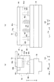
図1、図2(a)(b)、及び図6(a)(b)に示すように、箱曲げ用ダイ金型18は、下部テーブル16の上端部に設けられた取付ベース56を備えており、取付ベース56は、金型長さ方向に延びている。また、取付ベース56の上側には、金型長さ方向に延びたダイ金型本体58が複数の取付ボルト(図示省略)を介して設けられている。ダイ金型本体58は、上側に金型長さ方向に延びた凹部60dを有したダイボディ60と、ダイボディ60における凹部60dの背面側(後側)に着脱可能に設けられかつ金型長さ方向に延びた矩形断面の曲げ片62と有している。更に、曲げ片62は、その角部に、ワークWにおける短辺側の曲げフランジに相当する部分F’をL字状に曲げるための直角状の曲げ部62bを有しており、曲げ部62bは、金型長さ方向に延びている。なお、ダイ金型本体58から曲げ片62を省略して、ダイボディ60がワークWにおける短辺側の曲げフランジに相当する部分F’をL字状に曲げるための直角状の曲げ部(図示省略)を有してもよい。
As shown in FIGS. 1, 2 (a), (b), and FIGS. 6 (a), (b), the box bending die 18 includes a mounting
ダイボディ60の下部には、2つの段付き穴60hが金型長さ方向に間隔を置いて形成されており、各段付き穴60hの上端は、凹部60d側に開口している。また、ダイボディ60の下部における2つの段付き穴60hの間には、2つの支持穴60vが金型長さ方向に間隔を置いて形成されており、各支持穴60vの上端は、凹部60d側に開口している。
In the lower part of the
ダイボディ60の凹部60dには、金型長さ方向に延びた昇降ブロック64が昇降可能(上下方向へ移動可能)に設けられている。換言すれば、ダイ金型本体58における曲げ部62bの正面側には、金型長さ方向に延びた昇降ブロック64が昇降可能に設けられている。また、昇降ブロック64は、その上側に、ワークWを水平に支持する平坦面状の支持部64sを有しており、支持部64sは、金型長さ方向に延びている。昇降ブロック64の支持部64sは、一対のパンチボディ48の押圧部48p等(支持片38の押圧部38p及び支持爪40の押圧部40pを含む)と協働してワークWを挟持する。昇降ブロック64の支持部64sの後端は、各回転パンチ46の後端よりもワークWの厚み分だけ後方向に位置している。
An elevating
ダイボディ60の各段付き穴60hには、ストリッパボルト66が昇降可能に設けられており、各ストリッパボルト66の上端部(先端部)は、昇降ブロック64の下部に固定されている。各ストリッパボルト66の頭部は、昇降ブロック64の支持部64sが曲げ片62の上面と同じ高さに位置すると、ダイボディ60の各段付き穴60hの段部(段差部)に当接するように構成されている。また、ダイボディ60の各支持穴60vには、昇降ブロック64を上方向へ付勢する付勢部材としてコイルスプリング68が設けられている。なお、昇降ブロック64の支持部64sが曲げ片62の上面よりも僅かに高い高さに位置すると、各ストリッパボルト66の頭部がダイボディ60の各段付き穴60hの段部に当接するようにしてもよい。
In each stepped
ダイボディ60の背面には、一対のバックプレート54を上下方向へ摺動可能に案内するガイドプレート70が複数の取付ボルト(図示省略)を介して設けられており、各ガイドプレート70は、金型長さ方向に延びている。また、昇降ブロック64の支持部64sには、ワークWを金型長さ方向(左右方向)に位置決めするための位置決め部材72が設けられており、位置決め部材72は、金型幅方向(前後方向)に延びている。位置決め部材72は、金型長さ方向に位置調節可能であり、ワークWにおける長辺側の曲げフランジFを突当て可能な突当て面72sを有している。
A
続いて、本発明の実施形態の作用及び効果について説明する。 Subsequently, the operation and effect of the embodiment of the present invention will be described.
箱曲げ用金型セット10を用いてワークWにおける短辺側の曲げフランジに相当する部分F’の曲げ加工を行う前に、汎用の金型セットを用いてワークWにおける各長辺側の曲げフランジに相当する部分F’の曲げ加工を2回行う。これにより、ワークWにおける各長辺側にL字形状の曲げフランジFを形成する。 Before bending the portion F ′ corresponding to the bending flange on the short side of the work W using the box bending mold set 10, bending the long side of the work W using the general-purpose mold set. The bending process of the portion F 'corresponding to the flange is performed twice. Thus, an L-shaped bent flange F is formed on each long side of the work W.
次に、ワークWにおける一方の短辺側の曲げフランジに相当するF’の曲げ線が曲げ片62の曲げ部62bの後端に位置するように、ワークWを前後方向に位置決めする(図1参照)。また、ワークWにおける長辺側の曲げフランジFを位置決め部材72の突当て面72sに突き当てて、ワークWを左右方向に位置決めする。これにより、ワークWを箱曲げ用ダイ金型18に対してセットすることができる。
Next, the work W is positioned in the front-rear direction such that the bending line of F ′ corresponding to the bending flange on one short side of the work W is located at the rear end of the bending
続いて、上部テーブル12が下降することにより、各回転パンチ46が傾斜姿勢に保持された状態で、箱曲げ用パンチ金型14が下降して、各パンチボディ48の押圧部48pがワークWに接触する。そして、上部テーブル12の下降動作が継続されることにより、箱曲げ用パンチ金型14が下降しながら、各回転パンチ46が回転して傾斜姿勢から水平姿勢に切り替わる。すると、一対のパンチボディ48の押圧部48p等と昇降ブロック64の支持部64sとの協働によりワークWを挟持する。更に、上部テーブル12の下降動作が継続されことにより、箱曲げ用パンチ金型14が下降しながら、昇降ブロック64が複数のコイルスプリング68の付勢力に抗して下降する。すると、曲げ片62の曲げ部62bが昇降ブロック64に対して相対的に上昇する。これにより、図7及び図8に示すように、曲げ片62の曲げ部62bによってワークWにおける一方の短辺側の曲げフランジに相当する部分F’をL字状に曲げることができる。
Subsequently, as the upper table 12 is lowered, the box bending punches 14 are lowered in a state where the rotary punches 46 are held in the inclined posture, and the
ワークWの曲げ加工後に、図9に示すように、上部テーブル12が上昇することにより、箱曲げ用パンチ金型14が上昇しながら、各回転パンチ46がその自重による回転によって水平姿勢から傾斜姿勢に切り替わる。また、昇降ブロック64が複数のコイルスプリング68の付勢力によって元の高さ位置まで上昇する。これにより、箱曲げ用パンチ金型14及び箱曲げ用ダイ金型18、換言すれば、箱曲げ用金型セット10を元の状態に復帰させることができる。
After the work W is bent, as shown in FIG. 9, the upper table 12 is raised, so that the
前述の動作を繰り返すことにより、ワークWにおける一方の短辺側の曲げフランジに相当する部分F’の2回の曲げ加工を行って、ワークWにおける一方の短辺側にL字形状の曲げフランジFを形成することができる。また、ワークWを180度反転させて、前述の動作を繰り返すことにより、ワークWにおける他方の短辺側の曲げフランジに相当する部分F’の2回の曲げ加工を行って、ワークWにおける他方の短辺側にL字形状の曲げフランジFを形成することができる。これにより、4つのL字形状の曲げフランジFを有した箱製品Mを製作することができる。 By repeating the above-described operation, a portion F ′ corresponding to the bending flange on one short side of the work W is subjected to two bending processes, and an L-shaped bending flange is formed on one short side of the work W. F can be formed. Further, the work W is turned 180 degrees and the above operation is repeated, so that the part F ′ corresponding to the bending flange on the other short side of the work W is bent twice, and the other side of the work W is bent. An L-shaped bending flange F can be formed on the short side of. Thus, a box product M having four L-shaped bent flanges F can be manufactured.
前述のように、ワークWの曲げ加工後に上部テーブル12が上昇すると、各回転パンチ46がその自重による回転によって水平姿勢から傾斜姿勢に切り替わる。これにより、ワークWの箱曲げ加工の終了後又は途中に、各回転パンチ46とL字形状の曲げフランジFとの干渉を回避しつつ、箱曲げ用パンチ金型14を箱製品M又はワークWから抜くことができる。
As described above, when the upper table 12 is lifted after the work W is bent, each
また、前述のように、1つのヒンジピン42に一対の回転パンチ46が回転可能に設けられ、一対の回転パンチ46が金型長さ方向に対称的に配置されている。各回転パンチ46は、その回転によって水平姿勢と傾斜姿勢とに切り替わるよう構成されている。そのため、各回転パンチ46の回転動作の信頼性を確保しつつ、一対の回転パンチ46の最大の端部間距離を十分に短くすることができる。なお、一対の回転パンチ46の最大の端部間距離とは、各回転パンチ46を水平姿勢に切り替えた状態における一方の回転パンチ46の金型長さ方向外側の端部から他方の回転パンチ46の金型長さ方向の端部までの距離のことをいう。
As described above, a pair of
更に、前述のように、ユニットベース24、1つのヒンジピン42、一対の回転パンチ46、及び一対のボールプランジャ52は、パンチ金型本体20に対して着脱可能なパンチユニットPUを構成している。そのため、ユニットベース24(ベースブロック34)の後側面とパンチ金型本体20の段部20dの前側面との間にシム(図示省略)を介在させることにより、各回転パンチ46の金型幅方向の位置、換言すれば、昇降ブロック64の支持部64sの後端に対する各回転パンチ46の後端の前後方向の位置を変更することができる。併せて、一対の回転パンチ46の最大の端部間距離の異なる複数種のパンチユニットPUを用意することにより、パンチユニットPUの交換によって一対の回転パンチ46の最大の端部間距離を変更することができる。
Further, as described above, the
従って、本発明の実施形態によれば、各回転パンチ46の回転動作の信頼性を確保しつつ、一対の回転パンチ46の最大の端部間距離を十分に短くできるため、箱曲げ用金型セット10を用いて短辺側の寸法のより短い箱製品Mを製作することができる。
Therefore, according to the embodiment of the present invention, the maximum distance between the ends of the pair of
また、本発明の実施形態によれば、昇降ブロック64の支持部64sの後端に対する各回転パンチ46の後端の前後方向の位置を変更できるため、厚み(板厚)の異なる複数種のワークWの箱曲げを行うことができる。
Further, according to the embodiment of the present invention, since the position of the rear end of each
更に、本発明の実施形態によれば、パンチユニットPUの交換によって一対の回転パンチ46の最大の端部間距離を変更できるため、短辺側の寸法の異なる複数種の箱製品Mを製作することができる。
Further, according to the embodiment of the present invention, since the maximum distance between the ends of the pair of
なお、本発明は、前述の実施形態の説明に限るものでなく、次のように種々の態様で実施可能である。 The present invention is not limited to the above-described embodiment, but can be implemented in various modes as follows.
上部テーブル12が昇降する代わりに、下部テーブル16が昇降してもよい。換言すれば、箱曲げ用パンチ金型14が昇降する代わりに、箱曲げ用ダイ金型18が昇降してもよい。また、各パンチボディ48の押圧部48pを平坦面状に形成する代わりに、特許文献2に示すように、パンチ先端角を有した交差する2面状に形成してもよい。この場合には、箱曲げ用ダイ金型18に代えて、上面にV溝が形成された汎用ダイ金型(図示省略)を用いる。
Instead of the upper table 12 moving up and down, the lower table 16 may move up and down. In other words, instead of the
そして、本発明に包含される権利範囲は、前述の実施形態に限定されないものである。 The scope of rights included in the present invention is not limited to the above-described embodiment.
10 箱曲げ用金型セット
12 上部テーブル
14 箱曲げ用パンチ金型
16 下部テーブル
18 箱曲げ用ダイ金型
20 パンチ金型本体
20d パンチ金型本体の段部
22 シャンク部
24 ユニットベース
26 支持プレート
28 押え具
30 取付ボルト
32 規定板
34 ベースブロック
36 凸部
38 支持片(支持部材)
38p 支持片の押圧部
40 支持爪(支持部材)
40p 支持爪の押圧部
40b 支持爪のバック傾斜面
42 1つのヒンジピン
44 止め板
46 回転パンチ
48 パンチボディ
48p パンチボディの押圧部
48b パンチボディのバック傾斜面
48s パンチボディのサイド傾斜面
50 連結片
50s 連結片の当接面(ストッパ面)
52 ボールプランジャ
PU パンチユニット
54 バックプレート
56 取付ベース
58 ダイ金型本体
60 ダイボディ
60d ダイボディの凹部
60h ダイボディの段付き穴
60v ダイボディの支持穴
62 曲げ片
62b 曲げ片の曲げ部
64 昇降ブロック
64s 昇降ブロックの支持部
66 ストリッパボルト
68 コイルスプリング(付勢部材)
70 ガイドプレート
72 位置決め部材
72s 位置決め部材の突当て面
W ワーク(板金)
M 箱製品
F 曲げフランジ
F’ 曲げフランジに相当する部分
DESCRIPTION OF
38p Pressing portion of
40p Pressing portion of supporting
52 Ball Plunger
70
M Box product F Bending flange F 'Part corresponding to bending flange
Claims (7)
パンチ金型本体に金型幅方向に沿って設けられた1つのヒンジピンと、
1つの前記ヒンジピンに回転可能に設けられ、金型長さ方向に対称的に配置され、板状のワークを上方向から押圧する押圧部を有した一対の回転パンチと、備え、
各回転パンチは、その回転によって、前記押圧部が水平になる水平姿勢と、前記押圧部における金型長さ方向外側が金型長さ方向内側よりも低くなるように前記押圧部が水平方向に対して傾斜した傾斜姿勢とに切り替わるよう構成されると共に、ワークの曲げ加工後に自重よる回転によって前記水平姿勢から前記傾斜姿勢に切り替わるように構成されていることを特徴とする箱曲げ用パンチ金型。 A punch mold body,
One hinge pin provided on the punch die body along the die width direction;
A pair of rotary punches rotatably provided on one of the hinge pins, symmetrically arranged in a mold length direction, and having a pressing portion for pressing a plate-shaped work from above,
Each rotating punch has a horizontal posture in which the pressing portion is horizontal by the rotation thereof, and the pressing portion in the horizontal direction such that the outer side in the mold length direction of the pressing portion is lower than the inner side in the mold length direction. A punching die for box bending, wherein the punching die is configured to switch from the horizontal position to the tilted position by rotation due to its own weight after bending of the work. .
前記押圧部を有したパンチボディと、
前記パンチボディの金型長さ方向内側に形成され、1つの前記ヒンジピンに回転可能に連結する連結片と、を有し、
一対の前記回転パンチの前記連結片が重なるように金型幅方向に位置をずらしていることを特徴とする請求項1又は請求項2に記載の箱曲げ用パンチ金型。 Each rotating punch is
A punch body having the pressing portion;
A connecting piece formed inside the punch length direction of the punch body and rotatably connected to one of the hinge pins;
The punching die for box bending according to claim 1 or 2, wherein the positions of the pair of rotary punches are shifted in the die width direction so that the connecting pieces overlap with each other.
1つの前記ヒンジピンは、前記ユニットベースに設けられることにより、前記ユニットベースを介して前記パンチ金型本体に設けられており、
前記ユニットベース、1つの前記ヒンジピン、及び一対の前記回転パンチは、前記パンチ金型本体に対して着脱可能なパンチユニットを構成していることを特徴とする請求項1又は請求項2に記載の箱曲げ用パンチ金型。 A unit base provided detachably on the punch mold body,
One of the hinge pins is provided on the punch die main body via the unit base by being provided on the unit base,
The said unit base, one said hinge pin, and a pair of said rotary punches comprise the punch unit detachable with respect to the said punch die main body, The Claim 1 or Claim 2 characterized by the above-mentioned. Punch die for box bending.
前記パンチ金型本体に着脱可能に設けられたベースブロックと、
前記ベースブロックの下面に金型幅方向に間隔を置いて形成された一対の支持部材と、を有し、
1つの前記ヒンジピンは、一対の前記支持部材の間に金型幅方向に沿って連結するように設けられており、
各回転パンチは、
前記押圧部を有したパンチボディと、
前記パンチボディの金型長さ方向内側に形成され、1つの前記ヒンジピンに回転可能に連結する連結片と、を有し、
一対の前記回転パンチの前記連結片が一対の前記支持部材の間において重なるように金型幅方向に位置をずらしていることを特徴とする請求項4に記載の箱曲げ用パンチ金型。 The unit base is
A base block detachably provided on the punch mold body,
A pair of support members formed on the lower surface of the base block at intervals in the mold width direction,
One hinge pin is provided so as to be connected along a mold width direction between the pair of support members,
Each rotating punch is
A punch body having the pressing portion;
A connecting piece formed inside the punch length direction of the punch body and rotatably connected to one of the hinge pins;
The punching die for box bending according to claim 4, wherein the connecting pieces of the pair of rotary punches are shifted in the die width direction so as to overlap between the pair of support members.
前記箱曲げ用ダイ金型は、
上側に板状のワークにおける短辺側の曲げフランジに相当する部分を曲げるための直角状の曲げ部を有したダイ金型本体と、
前記ダイ金型本体における前記曲げ部の正面側に昇降可能に設けられ、上側にワークを支持しかつ一対の前記回転パンチの前記押圧部と協働してワークを挟持する平坦面状の支持部を有した昇降ブロックと、
前記昇降ブロックを上方向へ付勢する付勢部材と、を備えたことを特徴とする箱曲げ用金型セット。 It comprises a box bending die according to claim 2 and a box bending die.
The box bending die mold,
A die mold body having a right-angled bent portion for bending a portion corresponding to a short-side bent flange of a plate-shaped work on an upper side,
A flat surface-shaped support portion that is provided on the front side of the bent portion of the die mold body so as to be able to move up and down, supports the work on the upper side, and holds the work in cooperation with the pressing portions of the pair of rotary punches A lifting block having
A biasing member for biasing the lifting block upwards, comprising: a box bending mold set.
Priority Applications (1)
| Application Number | Priority Date | Filing Date | Title |
|---|---|---|---|
| JP2018176981A JP7089997B2 (en) | 2018-09-21 | 2018-09-21 | Box bending die and box bending die set |
Applications Claiming Priority (1)
| Application Number | Priority Date | Filing Date | Title |
|---|---|---|---|
| JP2018176981A JP7089997B2 (en) | 2018-09-21 | 2018-09-21 | Box bending die and box bending die set |
Publications (2)
| Publication Number | Publication Date |
|---|---|
| JP2020044569A true JP2020044569A (en) | 2020-03-26 |
| JP7089997B2 JP7089997B2 (en) | 2022-06-23 |
Family
ID=69900503
Family Applications (1)
| Application Number | Title | Priority Date | Filing Date |
|---|---|---|---|
| JP2018176981A Active JP7089997B2 (en) | 2018-09-21 | 2018-09-21 | Box bending die and box bending die set |
Country Status (1)
| Country | Link |
|---|---|
| JP (1) | JP7089997B2 (en) |
Cited By (1)
| Publication number | Priority date | Publication date | Assignee | Title |
|---|---|---|---|---|
| CN114054605A (en) * | 2021-10-27 | 2022-02-18 | 广州连捷精密技术有限公司 | Small-size iron-clad riveting machine |
Family Cites Families (1)
| Publication number | Priority date | Publication date | Assignee | Title |
|---|---|---|---|---|
| DE20310428U1 (en) | 2003-07-07 | 2003-09-18 | Trumpf Werkzeugmaschinen Gmbh | Bending tool with adjustable workpiece abutment segments and bending machine with such a bending tool |
-
2018
- 2018-09-21 JP JP2018176981A patent/JP7089997B2/en active Active
Cited By (1)
| Publication number | Priority date | Publication date | Assignee | Title |
|---|---|---|---|---|
| CN114054605A (en) * | 2021-10-27 | 2022-02-18 | 广州连捷精密技术有限公司 | Small-size iron-clad riveting machine |
Also Published As
| Publication number | Publication date |
|---|---|
| JP7089997B2 (en) | 2022-06-23 |
Similar Documents
| Publication | Publication Date | Title |
|---|---|---|
| JP5014069B2 (en) | Press mold | |
| WO2004030842A1 (en) | Method of processing formed product, and metal cope and metal drag used for the method | |
| JP2015174113A (en) | Press device | |
| JP2020044569A (en) | Box-bending punch die and box-bending punch die set | |
| JPWO2012090304A1 (en) | Press molding system | |
| JP2005021945A (en) | Metallic mold for press-forming and method for producing panel using it | |
| JP2008006470A (en) | Die for bending apparatus and method of working metal plate using the die for bending apparatus | |
| KR101904395B1 (en) | Roller Type Bending Press Device | |
| JP4376129B2 (en) | Arc-shaped bending method and apparatus for metal plate | |
| JP2007152417A (en) | Bending die device and bending method | |
| JP6159108B2 (en) | Bending mold | |
| CN207508095U (en) | A kind of notch flange stamping die of sheet metal | |
| JP7042119B2 (en) | Press equipment | |
| JP5035116B2 (en) | Press forming equipment | |
| JPH09276955A (en) | Die device and punch press using pie device | |
| WO2012090303A1 (en) | Press-molding device | |
| JP7307932B2 (en) | Method for manufacturing press machines and processed products | |
| JP5163554B2 (en) | Press machine | |
| JPH0428650Y2 (en) | ||
| CN217775210U (en) | Traceless bending die | |
| CN108015169A (en) | A kind of flanging molding die | |
| KR101748964B1 (en) | Material bending machine | |
| CN107639164B (en) | Workpiece bending die and workpiece bending processing assembly | |
| WO2018173997A1 (en) | Die mold for assymetrical bending, mold set for assymetrical bending, and bending processing method | |
| JP2004322167A (en) | Pressing apparatus |
Legal Events
| Date | Code | Title | Description |
|---|---|---|---|
| A621 | Written request for application examination |
Free format text: JAPANESE INTERMEDIATE CODE: A621 Effective date: 20210614 |
|
| A977 | Report on retrieval |
Free format text: JAPANESE INTERMEDIATE CODE: A971007 Effective date: 20220412 |
|
| A131 | Notification of reasons for refusal |
Free format text: JAPANESE INTERMEDIATE CODE: A131 Effective date: 20220421 |
|
| A521 | Request for written amendment filed |
Free format text: JAPANESE INTERMEDIATE CODE: A523 Effective date: 20220512 |
|
| TRDD | Decision of grant or rejection written | ||
| A01 | Written decision to grant a patent or to grant a registration (utility model) |
Free format text: JAPANESE INTERMEDIATE CODE: A01 Effective date: 20220517 |
|
| A61 | First payment of annual fees (during grant procedure) |
Free format text: JAPANESE INTERMEDIATE CODE: A61 Effective date: 20220613 |
|
| R150 | Certificate of patent or registration of utility model |
Ref document number: 7089997 Country of ref document: JP Free format text: JAPANESE INTERMEDIATE CODE: R150 |