JP2020003343A - Defect inspection device and defect inspection method - Google Patents
Defect inspection device and defect inspection method Download PDFInfo
- Publication number
- JP2020003343A JP2020003343A JP2018123063A JP2018123063A JP2020003343A JP 2020003343 A JP2020003343 A JP 2020003343A JP 2018123063 A JP2018123063 A JP 2018123063A JP 2018123063 A JP2018123063 A JP 2018123063A JP 2020003343 A JP2020003343 A JP 2020003343A
- Authority
- JP
- Japan
- Prior art keywords
- image
- light
- inspection object
- ring
- defect
- Prior art date
- Legal status (The legal status is an assumption and is not a legal conclusion. Google has not performed a legal analysis and makes no representation as to the accuracy of the status listed.)
- Pending
Links
Images


Abstract
Description
本発明は、被検査物の表面又は内部に、傷や異物等の欠陥が存在するか否かを検査する欠陥検査装置及び欠陥検査方法に係り、特に、暗視野照明としてリング状の照明光を用いた欠陥検査装置及び欠陥検査方法に関する。 The present invention relates to a defect inspection apparatus and a defect inspection method for inspecting whether or not a defect such as a scratch or a foreign substance is present on the surface or inside of an object to be inspected, and in particular, a ring-shaped illumination light as dark field illumination. The present invention relates to a defect inspection apparatus and a defect inspection method used.
例えば、めがねレンズは、その用途やデザイン性から、形状、曲率、屈折率、透過率、グラデーションコーティング等が異なり、それらの組合せで仕様が決まるため、少量多品種の製品である。従来、めがねレンズの表面又は内部に、傷、異物、コーティングむら等の欠陥が存在するか否かの検査は、検査員による目視検査が主流となっていた。しかしながら、目視検査は、検査員の経験や勘に頼る部分が大きいため精度にばらつきが発生し、また、検査員の人件費がレンズのコストアップの原因となり、検査の自動化が望まれていた。 For example, an eyeglass lens is a product of many kinds in a small quantity because the shape, curvature, refractive index, transmittance, gradation coating and the like are different depending on its use and design, and the specification is determined by a combination thereof. Conventionally, a visual inspection by an inspector has been mainly used to inspect whether or not a defect such as a scratch, a foreign substance, or an uneven coating exists on the surface or inside of the glasses lens. However, the visual inspection largely depends on the experience and intuition of the inspector, so that the accuracy varies, and the labor cost of the inspector causes an increase in the cost of the lens. Therefore, automation of the inspection has been desired.
めがねレンズの欠陥検査を、カメラ等の画像取得装置を用いて自動化しようとすると、レンズの種類毎に、照明装置及び画像取得装置の設定を変更する必要があった。これに対し、特許文献1には、複数のLEDと少なくとも2種類の異なる偏光方向を有する複数の偏光子を含み、複数のLEDを、複数のLED群に分割して駆動することにより、被測定物の状態によらず、高い検出感度を得るための調整が容易であり、検出感度の劣化要因となる照明光の発生を防ぐことが可能な照明装置、および光学装置が開示されている。
When attempting to automate the inspection of a lens for defects using an image acquisition device such as a camera, it is necessary to change the settings of the illumination device and the image acquisition device for each type of lens. On the other hand,
特許文献1の段落0002及び0003に記載されている様に、光学顕微鏡、光学測定機、画像観測装置等の光学装置では、観測方向、検出方向に対して斜めの方向から照明光を被測定物に照射する方式として、リング照明装置がよく用いられている。被検査物からの散乱光を観察する、リング照明装置を用いた暗視野観察は、レンズの傷や異物等の欠陥を検出する際にも、欠陥を高精度に検出するために非常に有効である。しかしながら、レンズの曲面の角度によっては、レンズの表面で照明光の反射が発生することがあり、反射光が発生した部分については、別の照明装置を使って検査を行うか、あるいは特許文献1に記載されている様に、複数のLED群の中から駆動するLED群を選択する必要があった。
As described in paragraphs 0002 and 0003 of
本発明の課題は、リング状の照明光を用い、被検査物の種類に応じて照明光を切り替える必要なく、被検査物の欠陥を高精度に検出することである。 An object of the present invention is to detect a defect of an inspection object with high accuracy without using a ring-shaped illumination light and switching the illumination light according to the type of the inspection object.
本発明の欠陥検査装置は、光を透過させる透明又は半透明な被検査物へ照射される、リング状の照明光の一部を表示するフラットパネルディスプレイ装置と、リング状の照明光を複数の区画に分割し、分割した各区画を、フラットパネルディスプレイ装置に順番に表示させる制御装置と、フラットパネルディスプレイ装置から、リング状の照明光の分割された各区画の光が照射された、被検査物の画像を取得して、画像信号を出力する画像取得装置と、画像取得装置から出力された各画像信号を処理して、被検査物の複数の画像を合成し、合成した画像から、被検査物の欠陥を検出する画像処理装置とを備えたことを特徴とする。 The defect inspection apparatus of the present invention is applied to a transparent or translucent inspection object that transmits light, a flat panel display device that displays a part of ring-shaped illumination light, and a plurality of ring-shaped illumination lights. A control device that divides each of the divided sections and sequentially displays each of the divided sections on a flat panel display device, and an inspection target in which the light of each divided section of the ring-shaped illumination light is emitted from the flat panel display device. An image acquisition device that acquires an image of an object and outputs an image signal; and processes each image signal output from the image acquisition device to synthesize a plurality of images of the inspected object. An image processing device for detecting a defect of the inspection object.
また、本発明の欠陥検査方法は、リング状の照明光を複数の区画に分割し、分割した各区画を、フラットパネルディスプレイ装置に順番に表示して、各区画の光を、光を透過させる透明又は半透明な被検査物へ順番に照射し、画像取得装置により、リング状の照明光の分割した各区画の光を照射した、被検査物の画像を取得して、画像信号を出力し、画像取得装置が出力した各画像信号を処理して、被検査物の複数の画像を合成し、合成した画像から、被検査物の欠陥を検出することを特徴とする。 Further, in the defect inspection method of the present invention, the ring-shaped illumination light is divided into a plurality of sections, the divided sections are sequentially displayed on a flat panel display device, and the light of each section is transmitted. By irradiating the transparent or translucent inspection object in order, the image acquisition device irradiates the light of each divided section of the ring-shaped illumination light, acquires an image of the inspection object, and outputs an image signal. Processing each image signal output by the image acquisition device, synthesizes a plurality of images of the inspection object, and detects a defect of the inspection object from the synthesized image.
リング状の照明光を複数の区画に分割し、分割した各区画を、フラットパネルディスプレイ装置に順番に表示して、各区画の光を、被検査物へ順番に照射し、画像取得装置により、リング状の照明光の分割した各区画の光を照射した、被検査物の画像を取得して、画像信号を出力するので、被検査物の種類に応じて照明光を切り替える必要はない。そして、画像取得装置が出力した各画像信号を処理して、被検査物の複数の画像を合成し、合成した画像から、被検査物の欠陥を検出するので、リング状の照明光を用い、被検査物の欠陥が高精度に検出される。 The ring-shaped illumination light is divided into a plurality of sections, and each of the divided sections is sequentially displayed on a flat panel display device, and the light of each section is sequentially irradiated on the inspection object. Since an image of the object to be inspected, which is obtained by irradiating the light of each of the divided sections of the ring-shaped illumination light, is obtained and an image signal is output, there is no need to switch the illumination light according to the type of the object to be inspected. Then, each image signal output by the image acquisition device is processed, a plurality of images of the inspection object are combined, and a defect of the inspection object is detected from the combined image. Defects of the inspection object are detected with high accuracy.
また、リング状の照明光の分割した各区画をフラットパネルディスプレイ装置に表示するので、リング状に配置したLED群と拡散板とを用いる場合に比べ、分解能が高くなり、かつ、拡散板から漏れた光が画像の合成の際に重複して加算されるのが防止され、被検査物の欠陥がより高精度に検出される。 In addition, since the divided sections of the ring-shaped illumination light are displayed on the flat panel display device, the resolution is higher than when the LED group and the diffuser arranged in a ring are used, and the leakage from the diffuser is increased. The combined light is prevented from being redundantly added during the synthesis of the images, and the defect of the inspection object is detected with higher accuracy.
あるいは、本発明の欠陥検査装置は、光を透過させる透明又は半透明な被検査物へ照射される光を発生する、リング状に配置された複数のLED群と、LED群から発生した光を拡散させる拡散板と、LED群を複数の区画に分割し、分割した各区画のLEDを順番に点灯させる制御装置と、LED群の分割された各区画のLEDの光が拡散板を通して照射された、被検査物の画像を取得して、画像信号を出力する画像取得装置と、画像取得装置から出力された各画像信号を処理して、被検査物の複数の画像を合成し、合成した画像から、被検査物の欠陥を検出する画像処理装置とを備えたことを特徴とする。 Alternatively, the defect inspection apparatus of the present invention generates a light that is emitted to a transparent or translucent inspection object that transmits light, a plurality of LED groups arranged in a ring shape, and light generated from the LED group. A diffusion plate to be diffused, a control device that divides the LED group into a plurality of sections, and sequentially turns on the LEDs in each of the divided sections, and light from the LEDs in each of the divided sections of the LED group is irradiated through the diffusion plate. An image acquisition device that acquires an image of an inspection object and outputs an image signal, processes each image signal output from the image acquisition device, synthesizes a plurality of images of the inspection object, and synthesizes the combined image. And an image processing device for detecting a defect of the inspection object.
また、本発明の欠陥検査方法は、複数のLED群をリング状に配置し、リング状に配置したLED群を複数の区画に分割し、分割した各区画のLEDを順番に点灯させて、各区画のLEDの光を、拡散板を通して、光を透過させる透明又は半透明な被検査物へ順番に照射し、画像取得装置により、分割した各区画のLEDの光を拡散板を通して照射した、被検査物の画像を取得して、画像信号を出力し、画像取得装置が出力した各画像信号を処理して、被検査物の複数の画像を合成し、合成した画像から、被検査物の欠陥を検出することを特徴とする。 Further, the defect inspection method of the present invention arranges a plurality of LED groups in a ring shape, divides the LED group arranged in a ring shape into a plurality of sections, and turns on the LEDs in each of the divided sections in order. The light of the LED of the section is sequentially irradiated to the transparent or translucent object through which light is transmitted through the diffusion plate, and the light of the LED of each divided section is irradiated through the diffusion plate by the image acquisition device. An image of the inspection object is acquired, an image signal is output, each image signal output by the image acquisition device is processed, a plurality of images of the inspection object are combined, and a defect of the inspection object is obtained from the combined image. Is detected.
複数のLED群をリング状に配置し、リング状に配置したLED群を複数の区画に分割し、分割した各区画のLEDを順番に点灯させて、各区画のLEDの光を、拡散板を通して、被検査物へ順番に照射し、画像取得装置により、分割した各区画のLEDの光を拡散板を通して照射した、被検査物の画像を取得して、画像信号を出力するので、被検査物の種類に応じて照明光を切り替える必要はない。そして、画像取得装置が出力した各画像信号を処理して、被検査物の複数の画像を合成し、合成した画像から、被検査物の欠陥を検出するので、リング状に配置されたLED群によるリング状の照明光を用い、被検査物の欠陥が高精度に検出される。 A plurality of LED groups are arranged in a ring shape, the LED group arranged in a ring shape is divided into a plurality of sections, the LEDs in each of the divided sections are sequentially turned on, and the light of the LEDs in each section is passed through the diffusion plate. Irradiates the inspection object in order, irradiates the LED light of each divided section through the diffusion plate by the image acquisition device, acquires an image of the inspection object, and outputs an image signal. There is no need to switch the illumination light according to the type of the illumination light. Then, each image signal output by the image acquisition device is processed, a plurality of images of the inspection object are synthesized, and a defect of the inspection object is detected from the synthesized image. The defect of the object to be inspected is detected with high accuracy by using the ring-shaped illumination light by the method.
さらに、本発明の欠陥検査装置は、画像処理装置が、画像取得装置から出力された各画像信号について、同じ位置の画素毎に、各画像信号を大きさ順に並べたとき、大きい方からm番目(m≧2)以降の各画像信号を加算して、被検査物の複数の画像を合成することを特徴とする。 Further, the defect inspection apparatus according to the present invention, when the image processing apparatus arranges each image signal for each pixel at the same position in order of size for each image signal output from the image acquisition apparatus, the m-th Each image signal after (m ≧ 2) is added to synthesize a plurality of images of the inspection object.
また、本発明の欠陥検査方法は、画像取得装置が出力した各画像信号について、同じ位置の画素毎に、各画像信号を大きさ順に並べたとき、大きい方からm番目(m≧2)以降の各画像信号を加算して、被検査物の複数の画像を合成することを特徴とする。 Further, the defect inspection method according to the present invention is characterized in that, for each image signal output from the image acquisition device, when each image signal is arranged in order of size for each pixel at the same position, the m-th (m ≧ 2) or more from the largest one Are added to synthesize a plurality of images of the inspection object.
画像取得装置が出力した各画像信号について、同じ位置の画素毎に、各画像信号を大きさ順に並べたとき、大きい方からm番目(m≧2)以降の各画像信号を加算して、被検査物の複数の画像を合成するので、リング状の照明光のいずれかの区画の光の照射、あるいは、リング状に配置したLED群のいずれかの区画のLEDの光の照射で、被検査物から透過光又は反射光が発生し、信号強度の非常に大きい画素が発生しても、信号強度の非常に大きい画素の画像信号は加算されず、透過光又は反射光の影響が除去される。従って、別の照明装置を用いる必要なく、被検査物の欠陥が検出される。 When each image signal output from the image acquisition device is arranged in order of size for each pixel at the same position, the m-th (m ≧ 2) or more image signals from the largest are added, and Since a plurality of images of the inspection object are combined, the object to be inspected can be irradiated by irradiating any one of the sections of the ring-shaped illumination light or irradiating the LED light of any one of the sections of the ring-shaped LED group. Even if transmitted or reflected light is generated from an object and a pixel with a very large signal intensity is generated, the image signal of the pixel with a very large signal intensity is not added, and the effect of the transmitted or reflected light is removed. . Therefore, the defect of the inspection object can be detected without using another illumination device.
さらに、本発明の欠陥検査装置は、フラットパネルディスプレイ装置を用いる場合に、画像処理装置が、画像取得装置から出力された各画像信号から、信号強度が所定値以上である画素を検出し、制御装置が、リング状の照明光の内径を、被検査物から透過光が発生する大きさに設定し、画像処理装置の検出結果に基づき、信号強度が所定値以上である画素がなくなるまで、設定したリング状の照明光の内径を拡大することを特徴とする。 Further, in the defect inspection apparatus of the present invention, when a flat panel display apparatus is used, the image processing apparatus detects a pixel whose signal intensity is equal to or more than a predetermined value from each image signal output from the image acquisition apparatus, and controls the image processing apparatus. The apparatus sets the inner diameter of the ring-shaped illumination light to a size at which transmitted light is generated from the object to be inspected, and based on the detection result of the image processing apparatus, sets until the pixel whose signal intensity is equal to or more than a predetermined value disappears. The inner diameter of the ring-shaped illumination light is enlarged.
また、本発明の欠陥検査方法は、フラットパネルディスプレイ装置を用いる場合に、リング状の照明光の内径を、被検査物から透過光が発生する大きさに設定し、画像取得装置が出力した各画像信号から、信号強度が所定値以上である画素を検出し、信号強度が所定値以上である画素がなくなるまで、設定したリング状の照明光の内径を拡大した後、被検査物の複数の画像を合成することを特徴とする。 Further, in the defect inspection method of the present invention, when a flat panel display device is used, the inner diameter of the ring-shaped illumination light is set to a size at which transmitted light is generated from the inspection object, and each image output by the image acquisition device is set. From the image signal, a pixel whose signal intensity is equal to or higher than a predetermined value is detected, and until the pixel whose signal intensity is equal to or higher than the predetermined value disappears, the inner diameter of the set ring-shaped illumination light is enlarged. It is characterized by combining images.
リング状の照明光は、被検査物から透過光が発生しない範囲で、被検査物から散乱光がより多く発生する様に、被検査物に近い位置に設けることが望ましい。リング状の照明光の内径を、被検査物から透過光が発生する大きさに設定し、画像取得装置が出力した各画像信号から、信号強度が所定値以上である画素を検出し、信号強度が所定値以上である画素がなくなるまで、設定したリング状の照明光の内径を拡大するので、リング状の照明光が、被検査物から透過光が発生しない範囲で、被検査物に近い位置に設けられる。 The ring-shaped illumination light is desirably provided at a position close to the object to be inspected so that more scattered light is generated from the object within a range where transmitted light is not generated from the object to be inspected. The inner diameter of the ring-shaped illumination light is set to a size at which transmitted light is generated from the inspection object, and from each image signal output by the image acquisition device, a pixel whose signal intensity is equal to or greater than a predetermined value is detected, and the signal intensity is detected. Until there is no pixel whose value is equal to or larger than a predetermined value, the set inner diameter of the ring-shaped illumination light is enlarged, so that the ring-shaped illumination light is positioned closer to the inspection object within a range in which no transmitted light is generated from the inspection object. Is provided.
本発明によれば、リング状の照明光を用い、被検査物の種類に応じて照明光を切り替える必要なく、被検査物の欠陥を高精度に検出することができる。 ADVANTAGE OF THE INVENTION According to this invention, the defect of a test object can be detected with high precision, without using a ring-shaped illumination light and switching illumination light according to the kind of a test object.
さらに、リング状の照明光の分割した各区画をフラットパネルディスプレイ装置に表示すると、リング状に配置したLED群と拡散板とを用いる場合に比べ、分解能を高くすることができ、かつ、拡散板から漏れた光が画像の合成の際に重複して加算されるのを防止することができるので、被検査物の欠陥をより高精度に検出することができる。 Furthermore, when the divided sections of the ring-shaped illumination light are displayed on a flat panel display device, the resolution can be increased as compared with a case where a ring-shaped LED group and a diffusion plate are used, and the diffusion plate It is possible to prevent the light leaked from from being redundantly added at the time of synthesizing the images, so that the defect of the inspection object can be detected with higher accuracy.
さらに、画像取得装置が出力した各画像信号について、同じ位置の画素毎に、各画像信号を大きさ順に並べたとき、大きい方からm番目(m≧2)以降の各画像信号を加算して、被検査物の複数の画像を合成することにより、リング状の照明光のいずれかの区画の光の照射、あるいは、リング状に配置したLED群のいずれかの区画のLEDの光の照射で、被検査物から透過光又は反射光が発生し、信号強度の非常に大きい画素が発生しても、信号強度の非常に大きい画素の画像信号を加算しないで、透過光又は反射光の影響を除去することができる。従って、別の照明装置を用いる必要なく、被検査物の欠陥を検出することができる。 Furthermore, for each image signal output by the image acquisition device, when the image signals are arranged in order of magnitude for each pixel at the same position, the m-th (m ≧ 2) or later image signals from the largest are added. By combining a plurality of images of the object to be inspected, irradiation of light in any of the sections of the ring-shaped illumination light, or irradiation of light of the LEDs in any of the sections of the LED group arranged in a ring can be performed. Even if transmitted light or reflected light is generated from the inspection object and a pixel having a very large signal intensity is generated, the influence of the transmitted light or the reflected light is not added without adding the image signal of the pixel having a very large signal intensity. Can be removed. Therefore, it is possible to detect a defect of the inspection object without using another illumination device.
さらに、フラットパネルディスプレイ装置を用いる場合に、リング状の照明光の内径を、被検査物から透過光が発生する大きさに設定し、画像取得装置が出力した各画像信号から、信号強度が所定値以上である画素を検出し、信号強度が所定値以上である画素がなくなるまで、設定したリング状の照明光の内径を拡大することにより、リング状の照明光を、被検査物から透過光が発生しない範囲で、被検査物に近づけ、被検査物から散乱光をより多く発生させて、被検査物の欠陥をより高精度に検出することができる。 Further, when a flat panel display device is used, the inner diameter of the ring-shaped illumination light is set to a size at which transmitted light is generated from the inspection object, and the signal intensity is determined from each image signal output by the image acquisition device. By detecting pixels having a value equal to or greater than the value and expanding the inner diameter of the set ring-shaped illumination light until there is no pixel having a signal intensity equal to or greater than a predetermined value, the ring-shaped illumination light is transmitted from the object to be inspected. Within the range in which does not occur, the object is brought closer to the inspection object, and more scattered light is generated from the inspection object, so that a defect of the inspection object can be detected with higher accuracy.
[実施の形態]
(第1の実施の形態)
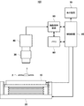
図1は、本発明の一実施の形態による欠陥検査装置の概略構成を示す図である。欠陥検査装置100は、ホルダー2、フラットパネルディスプレイ装置10、移動装置20、集光レンズ30、カメラ40、画像処理装置50、メモリ60、表示装置70、及び制御装置80を含んで構成されている。ホルダー2は、光を透過させる透明又は半透明な被検査物1の縁を、3つ以上の方向から挟み込んで保持する。なお、ホルダー2は、複数の被検査物1を保持し、集光レンズ30及びカメラ40に対して移動する構成であってもよい。あるいは、ホルダー2が複数の被検査物1を保持し、集光レンズ30及びカメラ40がホルダー2に対して移動する構成であってもよい。
[Embodiment]
(First Embodiment)
FIG. 1 is a diagram showing a schematic configuration of a defect inspection apparatus according to one embodiment of the present invention. The
フラットパネルディスプレイ装置10は、液晶ディスプレイ装置、プラズマディスプレイ装置、有機EL(Electroluminescence)ディスプレイ装置、プロジェクタ等からなり、制御装置80の制御により、リング状の照明光の一部を表示する。図2は、リング状の照明光の一例を示す図である。図2においては、黒色の背景に浮んだリング状の白い部分が、リング状の照明光11である。なお、リング状の照明光は、外周及び内周が円形のものに限らず、被検査物1の形状に応じて、外周及び内周が楕円形又は矩形、あるいは被検査物1の形状に合わせたものであってもよい。
The flat
図1において、制御装置80は、リング状の照明光を複数の区画に分割し、分割した各区画を、フラットパネルディスプレイ装置10に順番に表示させる。図3は、フラットパネルディスプレイ装置10に表示された、リング状の照明光の各区画の例を示す図である。本例は、図2に示したリング状の照明光11を、周方向に、図3(a)〜(h)の8つの区画に均等に分割した場合を示している。区画数は本例に限らず、リング状の照明光を7つ以下又は9つ以上に分割してもよい。また、分割の形態は、リング状の照明光を周方向に分割する場合に限らず、各区画の光が、被検査物1に対して異なる方向から入射し、又は異なる角度で入射する様に分割すればよい。
In FIG. 1, the
図1において、移動装置20は、フラットパネルディスプレイ装置10を上下に移動する。図4は、移動装置の動作を説明する図である。移動装置20は、テーブル21、ガイド22、及び昇降機構23を含んで構成されている。テーブル21は、フラットパネルディスプレイ装置10を搭載し、ガイド22に沿って図面上下方向へ移動する。昇降機構23は、テーブル21を上下させて、フラットパネルディスプレイ装置10を、被検査物1に近づく方向又は被検査物1から遠ざかる方向へ移動させる。これにより、図4(a),(b)に示す様に、フラットパネルディスプレイ装置10と被検査物1との距離Dが変化する。
In FIG. 1, a moving
図1において、集光レンズ30は、フラットパネルディスプレイ装置10から照射されて、被検査物1を透過した光を集光する。集光レンズ30には、入射瞳が無限遠にあり、主光線が光軸に対して平行なレンズが使用されている。カメラ40は、CCDやCMOS等の2次元センサーを有し、集光レンズ30により集光された光を受光して、被検査物1の画像を取得し、取得した画像の画像信号を出力する。
In FIG. 1, a
なお、図1に示した実施の形態では、フラットパネルディスプレイ装置10を、被検査物1を挟んでカメラ40と反対側(被検査物1の下方)に設けている。しかしながら、フラットパネルディスプレイ装置10をカメラ40と同じく被検査物1の上方に設け、フラットパネルディスプレイ装置10に表示されたリング状の照明光の一部を反射するミラーを、被検査物1の下方に設けてもよい。
In the embodiment shown in FIG. 1, the flat
画像処理装置50は、制御装置80の制御により、カメラ40から出力された画像信号を処理して、カメラ40により取得された被検査物1の複数の画像を合成し、合成した画像から、被検査物1の欠陥を検出する。メモリ60は、カメラ40から出力された画像信号、画像処理装置50により処理された画像信号、及び画像処理装置50により検出された、被検査物1の欠陥の情報を記憶する。表示装置70は、カメラ40により取得された画像、画像処理装置50により処理された画像、及び画像処理装置50により検出された、被検査物1の欠陥の位置、大きさ、形状等を表示する。制御装置80は、フラットパネルディスプレイ装置10、移動装置20、画像処理装置50、メモリ60、及び表示装置70を制御する。
The
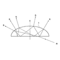
図5は、被検査物からの散乱光の発生を説明する図である。フラットパネルディスプレイ装置10に表示されたリング状の照明光の各区画からの光Rは、被検査物1の図面斜め下側から、被検査物1へ入射する。そして、被検査物1の内部へ透過した光は、被検査物1の内部で反射を繰り返す度に、その一部が散乱光Sとして被検査物1の外部へ放出される。散乱光Sは、リング状の照明光の各区画からの光Rが被検査物1へ入射した位置から、被検査物1の中心を通る中心線Cを挟んだ反対側で、多く発生する傾向にある。
FIG. 5 is a diagram illustrating generation of scattered light from the inspection object. The light R from each section of the ring-shaped illumination light displayed on the flat
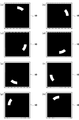
図6は、リング状の照明光の各区画の光が照射された被検査物の画像の例を示す図である。図6(a)〜(h)は、図3(a)〜(h)に対応して、図3(a)〜(h)に示すリング状の照明光の各区画の光が照射されたとき、カメラ40により取得されて表示装置70に表示された被検査物1の画像を、模式的に示したものでる。散乱光は、リング状の照明光の各区画からの光が被検査物1へ入射した位置の反対側で、多く発生する傾向にあるため、図6(a)〜(h)の各画像は、図3(a)〜(h)に示すリング状の照明光の各区画に対し、被検査物1の中心を挟んだ反対側でやや明るくなっている。
FIG. 6 is a diagram illustrating an example of an image of the inspection object irradiated with light of each section of the ring-shaped illumination light. 6 (a) to 6 (h) correspond to FIGS. 3 (a) to 3 (h), and the light of each section of the ring-shaped illumination light shown in FIGS. 3 (a) to 3 (h) is irradiated. At this time, the image of the
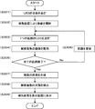
図7は、本発明の一実施の形態による欠陥検査装置の動作の一例を示すフローチャートである。まず、制御装置80は、リング状の照明光全体を、フラットパネルディスプレイ装置10に表示させる(ステップ101)。そして、制御装置80は、移動装置20により、フラットパネルディスプレイ装置10を上下に移動し、被検査物1の大きさや焦点距離に応じて、フラットパネルディスプレイ装置10と被検査物1との距離を調節する(ステップ102)。
FIG. 7 is a flowchart showing an example of the operation of the defect inspection device according to the embodiment of the present invention. First, the
次に、制御装置80は、リング状の照明光の1つの区画を、フラットパネルディスプレイ装置10に表示させる(ステップ103)。カメラ40は、被検査物1の画像を取得して、画像信号を出力する(ステップ104)。続いて、制御装置80は、リング状の照明光の全ての区画を、フラットパネルディスプレイ装置10に表示させ終ったか否かを判断し(ステップ105)、終っていない場合は、区画を変更して(ステップ106)、ステップ103へ戻る。
Next, the
全ての区画の表示が終了した場合、画像処理装置50は、制御装置80の制御により、カメラ40から出力された各画像信号を処理して、被検査物1の複数の画像を合成する(ステップ107)。このとき、画像処理装置50は、カメラ40から出力された各画像信号について、同じ位置の画素毎に、各画像信号を大きさ順に並べたとき、大きい方からm番目(m≧2)以降の各画像信号を加算して、被検査物1の複数の画像を合成する。
When the display of all the sections is completed, the
図8は、画像の合成処理を説明する図である。リング状の照明光を、図3(a)〜(h)に示す8つの区画に分割して、各区画の光を被検査物1へ順番に照射したとき、ある位置の画素の信号強度が、図8のn=1〜8に示す値であったとする。画像処理装置50は、これらの値を大きさ順に並べ変えて、m番目(m≧2)以降の各画像信号の値を加算する。例えば、m=4の場合は、(A)の式の通りとなる。
FIG. 8 is a diagram illustrating the image combining process. When the ring-shaped illumination light is divided into eight sections shown in FIGS. 3A to 3H and the light of each section is sequentially irradiated on the
カメラ40が出力した各画像信号について、同じ位置の画素毎に、各画像信号を大きさ順に並べたとき、大きい方からm番目(m≧2)以降の各画像信号を加算して、被検査物1の複数の画像を合成するので、リング状の照明光のいずれかの区画の光の照射で、被検査物1から透過光又は反射光が発生し、信号強度の非常に大きい画素が発生しても、信号強度の非常に大きい画素の画像信号は加算されず、透過光又は反射光の影響が除去される。従って、別の照明装置を用いる必要なく、被検査物1の欠陥が検出される。
When the image signals output from the
なお、図8において、例えば、m=4のとした理由は、リング状の照明光の分割したいずれかの区画の光の照射で透過光又は反射光が発生した場合、その区画に隣接する左右の区画の光の照射によっても、信号強度の大きい画素が発生する恐れがあるので、隣接する左右の区画を含む3つの区画の光を照射したときの画像の画素の画像信号を、除外するためである。しかしながら、mは、2、3、又は5以上であってもよい。 In FIG. 8, for example, the reason for setting m = 4 is that when transmitted light or reflected light is generated by irradiation of light in one of the divided sections of the ring-shaped illumination light, the left and right adjacent to that section There is a possibility that a pixel having a large signal intensity may be generated even by the irradiation of the light of the section (3). Therefore, the image signal of the pixel of the image when the light of the three sections including the adjacent left and right sections is irradiated is excluded. It is. However, m may be 2, 3, or 5 or more.
また、カメラ40から出力された各画像信号について、同じ位置の画素毎に、各画像信号を大きさ順に並べたとき、小さい方から所定数の画像信号も加算しない様にすると、カメラ40の各画像信号に発生するノイズの影響を除去することができる。従って、被検査物1の欠陥をさらに高精度に検出することができる。
In addition, for each image signal output from the
図7において、次に、画像処理装置50は、合成した画像から、被検査物1の欠陥を検出する(ステップ108)。制御装置80は、画像処理装置50の検出結果を、表示装置に表示する(ステップ109)。
In FIG. 7, next, the
図9は、合成した画像の一例を示す図である。図9は、図6(a)〜(h)に示した被検査物1の各画像を合成した画像を、図6と同様に模式的に示したものである。なお、図9では、被検査物1の丸い形が白っぽく表示されているが、実際の暗視野の画像では、黒色の背景に対して、少し明度の高い灰色(グレー)として観察される。そして、図9には、被検査物1の欠陥が表示されていないが、被検査物1の表面又は内部に傷、異物等の欠陥が存在すると、欠陥の存在する位置で散乱光の強度が他の部分より強くなり、その位置の画素の輝度が高くなる。画像処理装置50は、合成した画像の画像信号から、信号強度が所定のしきい値以上である画像信号を検出することにより、被検査物1の欠陥の位置、大きさ、形状等を検出する。
FIG. 9 is a diagram illustrating an example of a combined image. FIG. 9 schematically shows an image obtained by synthesizing the images of the
リング状の照明光を複数の区画に分割し、分割した各区画を、フラットパネルディスプレイ装置10に順番に表示して、各区画の光を、被検査物1へ順番に照射し、カメラ40により、リング状の照明光の分割した各区画の光を照射した、被検査物1の画像を取得して、画像信号を出力するので、被検査物1の種類に応じて照明光を切り替える必要はない。そして、カメラ40が出力した各画像信号を処理して、被検査物1の複数の画像を合成し、合成した画像から、被検査物1の欠陥を検出するので、リング状の照明光を用い、被検査物1の欠陥が高精度に検出される。
The ring-shaped illumination light is divided into a plurality of sections, and each of the divided sections is sequentially displayed on the flat
また、リング状の照明光の分割した各区画をフラットパネルディスプレイ装置10に表示するので、リング状に配置したLED群と拡散板とを用いる第2の実施の形態に比べ、分解能が高くなり、かつ、拡散板から漏れた光が画像の合成の際に重複して加算されるのが防止され、被検査物1の欠陥がより高精度に検出される。
Further, since the divided sections of the ring-shaped illumination light are displayed on the flat
図10は、本発明の一実施の形態による欠陥検査装置の動作の他の例を示すフローチャートである。まず、制御装置80は、移動装置20により、フラットパネルディスプレイ装置10を上下に移動し、被検査物1の大きさや焦点距離に応じて、フラットパネルディスプレイ装置10と被検査物1との距離を調節する(ステップ201)。次に制御装置80は、リング状の照明光の内径を設定する(ステップ202−1)。このとき、制御装置80は、リング状の照明光の内径を、被検査物1から透過光が発生する大きさに設定する。
FIG. 10 is a flowchart illustrating another example of the operation of the defect inspection device according to the embodiment of the present invention. First, the
次に、制御装置80は、リング状の照明光全体を、フラットパネルディスプレイ装置10に表示させる(ステップ202−2)。画像処理装置50は、制御装置80の制御により、カメラ40から出力された画像信号から、信号強度が所定値以上である画素を検出し、制御装置80は、画像処理装置50の検出結果から、信号強度が所定値以上である画素が存在したか否かを判断する(ステップ202−3)。
Next, the
信号強度が所定値以上である画素が存在した場合、制御装置80は、ステップ202−1で設定したリング状の照明光の内径を一定値だけ拡大して(ステップ202−4)、ステップ202−1へ戻る。そして、信号強度が所定値以上である画素がなくなるまで、ステップ202−1からステップ202−4を繰り返す。
If there is a pixel whose signal intensity is equal to or greater than the predetermined value, the
信号強度が所定値以上である画素が存在しなくなると、それ以降のステップ203〜209の処理は、図7のステップ103〜109の処理と同様である。 When there is no pixel whose signal strength is equal to or more than the predetermined value, the subsequent processing of steps 203 to 209 is the same as the processing of steps 103 to 109 in FIG.
リング状の照明光は、被検査物1から透過光が発生しない範囲で、被検査物1から散乱光がより多く発生する様に、被検査物1に近い位置に設けることが望ましい。リング状の照明光の内径を、被検査物1から透過光が発生する大きさに設定し、カメラ40が出力した各画像信号から、信号強度が所定値以上である画素を検出し、信号強度が所定値以上である画素がなくなるまで、設定したリング状の照明光の内径を拡大するので、リング状の照明光が、被検査物1から透過光が発生しない範囲で、被検査物1に近い位置に設けられる。
The ring-shaped illumination light is desirably provided at a position close to the
(第1の実施の形態の効果)
以上説明した第1の実施の形態によれば、次の効果を奏する。
(1)リング状の照明光を用い、被検査物1の種類に応じて照明光を切り替える必要なく、被検査物1の欠陥を高精度に検出することができる。
(Effects of the First Embodiment)
According to the first embodiment described above, the following effects can be obtained.
(1) Using the ring-shaped illumination light, the defect of the
(2)さらに、リング状の照明光の分割した各区画をフラットパネルディスプレイ装置10に表示することにより、リング状に配置したLED群と拡散板とを用いる第2の実施の形態に比べ、分解能を高くすることができ、かつ、拡散板から漏れた光が画像の合成の際に重複して加算されるのを防止することができるので、被検査物1の欠陥をより高精度に検出することができる。
(2) Further, by displaying each of the divided sections of the ring-shaped illumination light on the flat
(3)さらに、カメラ40が出力した各画像信号について、同じ位置の画素毎に、各画像信号を大きさ順に並べたとき、大きい方からm番目(m≧2)以降の各画像信号を加算して、被検査物1の複数の画像を合成することにより、リング状の照明光のいずれかの区画の光の照射で、被検査物1から透過光又は反射光が発生し、信号強度の非常に大きい画素が発生しても、信号強度の非常に大きい画素の画像信号を加算しないで、透過光又は反射光の影響を除去することができる。従って、別の照明装置を用いる必要なく、被検査物1の欠陥を検出することができる。
(3) Further, for each image signal output by the
(4)さらに、リング状の照明光の内径を、被検査物1から透過光が発生する大きさに設定し、カメラ40が出力した各画像信号から、信号強度が所定値以上である画素を検出し、信号強度が所定値以上である画素がなくなるまで、設定したリング状の照明光の内径を拡大することにより、リング状の照明光を、被検査物1から透過光が発生しない範囲で、被検査物1に近づけ、被検査物1から散乱光をより多く発生させて、被検査物1の欠陥をより高精度に検出することができる。
(4) Further, the inner diameter of the ring-shaped illumination light is set to a size at which transmitted light is generated from the
(第2の実施の形態)
本発明の他の実施の形態として、図1のフラットパネルディスプレイ装置10の代わりに、リング状に配置したLED群と拡散板とを有する照明装置を用いてもよい。図11(a)は本発明の他の実施の形態による欠陥検査装置の照明装置の上面図、図11(b)は図11(a)のB−B部断面図である。照明装置90は、ケース91、複数のLED92群、及び拡散板93を含んで構成されている。
(Second embodiment)
As another embodiment of the present invention, instead of the flat
図11(a)において、ケース91は、上方から見てリング形状であり、ケース91内には、破線で示す複数のLED92群が、リング状に配置されている。図11(b)において、ケース91の内壁には、複数のLED92群が発生する光を反射するために、ミラー加工が施されている。そして、ケース91の上面には、凹面93aを有する拡散板93が取り付けられている。拡散板93は、複数のLED92群が発生する光を拡散させ、これにより、被検査物1の表面に各LED92の形状が写り込むのが防止される。
In FIG. 11A, the
図1の制御装置80は、リング状に配置された複数のLED92群を複数の区画に分割し、分割した各区画のLED92を順番に点灯させる。図12は、分割された各区画のLEDの例を示す図である。本例は、図12(a)に破線で示したリング状に配置された複数のLED92群を、リングの周方向に、90a〜90hの8つの区画に均等に分割した場合を示している。区画数は本例に限らず、リング状に配置された複数のLED92群を、7つ以下又は9つ以上に分割してもよい。また、分割の形態は、リング状に配置された複数のLED92群を、リングの周方向に分割する場合に限らず、各区画のLEDの光が、被検査物1に対して異なる方向から入射し、又は異なる角度で入射する様に分割すればよい。
The
図13は、本発明の他の実施の形態による欠陥検査装置の動作を示すフローチャートである。まず、制御装置80は、リング状に配置されたLED92群全体を、点灯させる(ステップ301)。そして、制御装置80は、移動装置20により、照明装置90を上下に移動し、被検査物1の大きさや焦点距離に応じて、照明装置90と被検査物1との距離を調節する(ステップ302)。
FIG. 13 is a flowchart showing the operation of the defect inspection apparatus according to another embodiment of the present invention. First, the
次に、制御装置80は、LED92群の分割した1つの区画のLED92を点灯させる(ステップ303)。カメラ40は、被検査物1の画像を取得して、画像信号を出力する(ステップ304)。続いて、制御装置80は、全ての区画のLED92を、点灯させ終ったか否かを判断し(ステップ305)、終っていない場合は、区画を変更して(ステップ306)、ステップ303へ戻る。
Next, the
全ての区画のLED92の点灯が終了した場合、画像処理装置50は、制御装置80の制御により、カメラ40から出力された各画像信号を処理して、被検査物1の複数の画像を合成する(ステップ307)。合成処理の方法は、図8を用いて説明した、第1の実施の形態と同様である。
When the lighting of the
カメラ40が出力した各画像信号について、同じ位置の画素毎に、各画像信号を大きさ順に並べたとき、大きい方からm番目(m≧2)以降の各画像信号を加算して、被検査物1の複数の画像を合成するので、リング状に配置したLED92群のいずれかの区画のLED92の光の照射で、被検査物1から透過光又は反射光が発生し、信号強度の非常に大きい画素が発生しても、信号強度の非常に大きい画素の画像信号は加算されず、透過光又は反射光の影響が除去される。従って、別の照明装置を用いる必要なく、被検査物1の欠陥が検出される。
When the image signals output from the
次に、画像処理装置50は、合成した画像から、被検査物1の欠陥を検出する(ステップ308)。制御装置80は、画像処理装置50の検出結果を、表示装置に表示する(ステップ309)。
Next, the
複数のLED92群をリング状に配置し、リング状に配置したLED92群を複数の区画に分割し、分割した各区画のLED92を順番に点灯させて、各区画のLED92の光を、拡散板93を通して、被検査物1へ順番に照射し、カメラ40により、分割した各区画のLED92の光を拡散板93を通して照射した、被検査物1の画像を取得して、画像信号を出力するので、被検査物1の種類に応じて照明光を切り替える必要はない。そして、カメラ40が出力した各画像信号を処理して、被検査物1の複数の画像を合成し、合成した画像から、被検査物1の欠陥を検出するので、リング状に配置されたLED92群によるリング状の照明光を用い、被検査物1の欠陥が高精度に検出される。
A plurality of groups of
(第2の実施の形態の効果)
以上説明した第2の実施の形態によれば、次の効果を奏する。
(1)リング状に配置されたLED92群によるリング状の照明光を用い、被検査物1の種類に応じて照明光を切り替える必要なく、被検査物1の欠陥を高精度に検出することができる。
(Effect of Second Embodiment)
According to the second embodiment described above, the following effects can be obtained.
(1) It is possible to detect a defect of the
(2)さらに、カメラ40が出力した各画像信号について、同じ位置の画素毎に、各画像信号を大きさ順に並べたとき、大きい方からm番目(m≧2)以降の各画像信号を加算して、被検査物1の複数の画像を合成することにより、リング状に配置したLED92群のいずれかの区画のLED92の光の照射で、被検査物1から透過光又は反射光が発生し、信号強度の非常に大きい画素が発生しても、信号強度の非常に大きい画素の画像信号を加算しないで、透過光又は反射光の影響を除去することができる。従って、別の照明装置を用いる必要なく、被検査物1の欠陥を検出することができる。
(2) Further, when the image signals output from the
本発明は、レンズ等の光学部品の欠陥検査に限らず、パイプやガラス等の、光を透過させる透明又は半透明な被検査物の欠陥検査にも適用することができる。 INDUSTRIAL APPLICABILITY The present invention can be applied not only to defect inspection of optical components such as lenses, but also to defect inspection of transparent or translucent objects such as pipes and glass that transmit light.
1 被検査物
2 ホルダー
10 フラットパネルディスプレイ装置
11 リング状の照明光
20 移動装置
21 テーブル
22 ガイド
23 昇降機構
30 集光レンズ
40 カメラ
50 画像処理装置
60 メモリ
70 表示装置
80 制御装置
90 照明装置
91 ケース
92 LED
93 拡散板
100 欠陥検査装置
DESCRIPTION OF
93
Claims (10)
前記リング状の照明光を複数の区画に分割し、分割した各区画を、前記フラットパネルディスプレイ装置に順番に表示させる制御装置と、
前記フラットパネルディスプレイ装置から、前記リング状の照明光の分割された各区画の光が照射された、前記被検査物の画像を取得して、画像信号を出力する画像取得装置と、
前記画像取得装置から出力された各画像信号を処理して、前記被検査物の複数の画像を合成し、合成した画像から、前記被検査物の欠陥を検出する画像処理装置とを備えた
ことを特徴とする欠陥検査装置。 Irradiated on a transparent or translucent test object that transmits light, a flat panel display device that displays a part of ring-shaped illumination light,
A control device that divides the ring-shaped illumination light into a plurality of sections, and the divided sections are sequentially displayed on the flat panel display device,
From the flat panel display device, the light of each of the divided sections of the ring-shaped illumination light is irradiated, to obtain an image of the inspection object, an image acquisition device that outputs an image signal,
An image processing device that processes each image signal output from the image acquisition device, combines a plurality of images of the inspection object, and detects a defect of the inspection object from the combined image. A defect inspection apparatus characterized by the above-mentioned.
ことを特徴とする請求項1に記載の欠陥検査装置。 The image processing apparatus is configured such that, for each image signal output from the image acquisition apparatus, for each pixel at the same position, when arranging the image signals in order of magnitude, each of the m-th (m ≧ 2) and subsequent The defect inspection apparatus according to claim 1, wherein a plurality of images of the inspection object are synthesized by adding image signals.
前記制御装置は、前記リング状の照明光の内径を、前記被検査物から透過光が発生する大きさに設定し、前記画像処理装置の検出結果に基づき、信号強度が所定値以上である画素がなくなるまで、設定した前記リング状の照明光の内径を拡大する
ことを特徴とする請求項1又は請求項2に記載の欠陥検査装置。 The image processing device detects, from each image signal output from the image acquisition device, a pixel whose signal intensity is equal to or greater than a predetermined value,
The control device sets the inner diameter of the ring-shaped illumination light to a size at which transmitted light is generated from the inspection object, and based on a detection result of the image processing device, a pixel whose signal intensity is equal to or more than a predetermined value. 3. The defect inspection apparatus according to claim 1, wherein the set inner diameter of the ring-shaped illumination light is enlarged until no longer exists. 4.
前記LED群から発生した光を拡散させる拡散板と、
前記LED群を複数の区画に分割し、分割した各区画のLEDを順番に点灯させる制御装置と、
前記LED群の分割された各区画のLEDの光が前記拡散板を通して照射された、前記被検査物の画像を取得して、画像信号を出力する画像取得装置と、
前記画像取得装置から出力された各画像信号を処理して、前記被検査物の複数の画像を合成し、合成した画像から、前記被検査物の欠陥を検出する画像処理装置とを備えた
ことを特徴とする欠陥検査装置。 A plurality of LED groups arranged in a ring shape, which emit light to be transmitted to a transparent or translucent inspection object that transmits light,
A diffusion plate for diffusing light generated from the LED group;
A control device that divides the LED group into a plurality of sections, and sequentially turns on the LEDs in each of the divided sections;
An image acquisition device that acquires an image of the object to be inspected, in which the light of the LEDs in each of the divided sections of the LED group is irradiated through the diffusion plate, and outputs an image signal,
An image processing device that processes each image signal output from the image acquisition device, combines a plurality of images of the inspection object, and detects a defect of the inspection object from the combined image. A defect inspection apparatus characterized by the above-mentioned.
ことを特徴とする請求項4に記載の欠陥検査装置。 The image processing apparatus is configured such that, for each image signal output from the image acquisition apparatus, for each pixel at the same position, when arranging the image signals in order of magnitude, each of the m-th (m ≧ 2) and subsequent The defect inspection apparatus according to claim 4, wherein a plurality of images of the inspection object are synthesized by adding image signals.
分割した各区画を、フラットパネルディスプレイ装置に順番に表示して、各区画の光を、光を透過させる透明又は半透明な被検査物へ順番に照射し、
画像取得装置により、前記リング状の照明光の分割した各区画の光を照射した、前記被検査物の画像を取得して、画像信号を出力し、
前記画像取得装置が出力した各画像信号を処理して、前記被検査物の複数の画像を合成し、合成した画像から、前記被検査物の欠陥を検出する
ことを特徴とする欠陥検査方法。 Divide the ring-shaped illumination light into multiple sections,
Each of the divided sections is sequentially displayed on a flat panel display device, and the light of each section is sequentially radiated to a transparent or translucent test object that transmits light,
By the image acquisition device, irradiating the light of each divided section of the ring-shaped illumination light, to acquire an image of the inspection object, output an image signal,
A defect inspection method, comprising processing each image signal output by the image acquisition device, synthesizing a plurality of images of the inspection object, and detecting a defect of the inspection object from the synthesized image.
ことを特徴とする請求項6に記載の欠陥検査方法。 For each image signal output by the image acquisition device, for each pixel at the same position, when arranging the image signals in order of magnitude, adding the m-th (m ≧ 2) or later image signals from the largest, The defect inspection method according to claim 6, wherein a plurality of images of the inspection object are combined.
前記画像取得装置が出力した各画像信号から、信号強度が所定値以上である画素を検出し、
信号強度が所定値以上である画素がなくなるまで、設定した前記リング状の照明光の内径を拡大した後、
前記被検査物の複数の画像を合成する
ことを特徴とする請求項6又は請求項7に記載の欠陥検査方法。 The inner diameter of the ring-shaped illumination light is set to a size at which transmitted light is generated from the inspection object,
From each image signal output by the image acquisition device, a pixel whose signal intensity is equal to or greater than a predetermined value is detected,
Until there is no pixel whose signal intensity is equal to or greater than a predetermined value, after expanding the set inner diameter of the ring-shaped illumination light,
The defect inspection method according to claim 6, wherein a plurality of images of the inspection object are combined.
リング状に配置した前記LED群を複数の区画に分割し、
分割した各区画のLEDを順番に点灯させて、各区画のLEDの光を、拡散板を通して、光を透過させる透明又は半透明な被検査物へ順番に照射し、
画像取得装置により、分割した各区画のLEDの光を前記拡散板を通して照射した、前記被検査物の画像を取得して、画像信号を出力し、
前記画像取得装置が出力した各画像信号を処理して、前記被検査物の複数の画像を合成し、合成した画像から、前記被検査物の欠陥を検出する
ことを特徴とする欠陥検査方法。 Arrange a plurality of LED groups in a ring shape,
Dividing the LED group arranged in a ring shape into a plurality of sections,
The LEDs of each of the divided sections are sequentially turned on, and the light of the LEDs of each section is sequentially irradiated on a transparent or translucent test object that transmits light through a diffusion plate,
The image acquisition device irradiates the light of the LED of each divided section through the diffusion plate, acquires an image of the inspection object, outputs an image signal,
A defect inspection method, comprising processing each image signal output by the image acquisition device, synthesizing a plurality of images of the inspection object, and detecting a defect of the inspection object from the synthesized image.
ことを特徴とする請求項9に記載の欠陥検査方法。 For each image signal output by the image acquisition device, for each pixel at the same position, when arranging the image signals in order of magnitude, adding the m-th (m ≧ 2) or later image signals from the largest, The defect inspection method according to claim 9, wherein a plurality of images of the inspection object are combined.
Priority Applications (1)
| Application Number | Priority Date | Filing Date | Title |
|---|---|---|---|
| JP2018123063A JP2020003343A (en) | 2018-06-28 | 2018-06-28 | Defect inspection device and defect inspection method |
Applications Claiming Priority (1)
| Application Number | Priority Date | Filing Date | Title |
|---|---|---|---|
| JP2018123063A JP2020003343A (en) | 2018-06-28 | 2018-06-28 | Defect inspection device and defect inspection method |
Publications (1)
| Publication Number | Publication Date |
|---|---|
| JP2020003343A true JP2020003343A (en) | 2020-01-09 |
Family
ID=69099761
Family Applications (1)
| Application Number | Title | Priority Date | Filing Date |
|---|---|---|---|
| JP2018123063A Pending JP2020003343A (en) | 2018-06-28 | 2018-06-28 | Defect inspection device and defect inspection method |
Country Status (1)
| Country | Link |
|---|---|
| JP (1) | JP2020003343A (en) |
Cited By (1)
| Publication number | Priority date | Publication date | Assignee | Title |
|---|---|---|---|---|
| WO2024001495A1 (en) * | 2022-06-29 | 2024-01-04 | 京东方科技集团股份有限公司 | Fault detection method and device for display screen, and inspection robot |
Citations (4)
| Publication number | Priority date | Publication date | Assignee | Title |
|---|---|---|---|---|
| JP2007040783A (en) * | 2005-08-02 | 2007-02-15 | Shinko Seiki Co Ltd | Container for visual inspection |
| US20090303465A1 (en) * | 2008-06-05 | 2009-12-10 | Julie Ann Clements | Multi-imaging automated inspection methods and systems for wet ophthalmic lenses |
| JP2012042254A (en) * | 2010-08-16 | 2012-03-01 | Canon Inc | Method for inspecting lens defect |
| JP2018054576A (en) * | 2016-09-30 | 2018-04-05 | 東海光学株式会社 | Visual inspection device for lens |
-
2018
- 2018-06-28 JP JP2018123063A patent/JP2020003343A/en active Pending
Patent Citations (4)
| Publication number | Priority date | Publication date | Assignee | Title |
|---|---|---|---|---|
| JP2007040783A (en) * | 2005-08-02 | 2007-02-15 | Shinko Seiki Co Ltd | Container for visual inspection |
| US20090303465A1 (en) * | 2008-06-05 | 2009-12-10 | Julie Ann Clements | Multi-imaging automated inspection methods and systems for wet ophthalmic lenses |
| JP2012042254A (en) * | 2010-08-16 | 2012-03-01 | Canon Inc | Method for inspecting lens defect |
| JP2018054576A (en) * | 2016-09-30 | 2018-04-05 | 東海光学株式会社 | Visual inspection device for lens |
Cited By (1)
| Publication number | Priority date | Publication date | Assignee | Title |
|---|---|---|---|---|
| WO2024001495A1 (en) * | 2022-06-29 | 2024-01-04 | 京东方科技集团股份有限公司 | Fault detection method and device for display screen, and inspection robot |
Similar Documents
| Publication | Publication Date | Title |
|---|---|---|
| US10600173B2 (en) | Multi-optic vision device utilizing area-scanning for detecting defects | |
| JP2008501960A (en) | Device for controlling transparent or reflective parts | |
| JP2008249568A (en) | Visual examination device | |
| JP2007183225A (en) | Light radiation device, surface shape inspection system, and surface shape inspection method | |
| US20180213134A1 (en) | Optical Inspection System | |
| CN105486690A (en) | Optical detection device | |
| CN113686879A (en) | Optical film defect visual detection system and method | |
| TWI702381B (en) | Defect inspection device and defect inspection method | |
| JPWO2007132925A1 (en) | Surface inspection device | |
| JP4668354B1 (en) | Transparent tube bubble detection device and bubble detection method | |
| JP2020041800A (en) | Visual inspection device and inspection system | |
| JP2020003343A (en) | Defect inspection device and defect inspection method | |
| JP2007033339A (en) | Method and device for determining detection of fisheye | |
| JP2017166903A (en) | Defect inspection device and defect inspection method | |
| KR101520636B1 (en) | Optical Method and Apparatus of Image Acquisition and Illumination on Irregular Surface | |
| CN110658207A (en) | Detection method and device for distinguishing foreign matters inside and outside non-polarizing film | |
| JP2009139365A (en) | Device and method for defect inspection of translucent material | |
| KR101555542B1 (en) | inspecting machine for flat panel | |
| JP2014169988A (en) | Defect inspection device of transparent body or reflection body | |
| JP2014025884A (en) | Visual inspection method and visual inspection device | |
| KR20110119082A (en) | Apparatus for inspecting substrate and method of inspecting substrate | |
| CN111272761A (en) | Method and apparatus for inspecting surface defect of light-transmitting member | |
| JP2020012652A (en) | Lens checker | |
| KR20110133183A (en) | Inspecting machine for flat panel | |
| JP2002014058A (en) | Method and apparatus for checking |
Legal Events
| Date | Code | Title | Description |
|---|---|---|---|
| A621 | Written request for application examination |
Free format text: JAPANESE INTERMEDIATE CODE: A621 Effective date: 20210513 |
|
| A977 | Report on retrieval |
Free format text: JAPANESE INTERMEDIATE CODE: A971007 Effective date: 20220318 |
|
| A131 | Notification of reasons for refusal |
Free format text: JAPANESE INTERMEDIATE CODE: A131 Effective date: 20220412 |
|
| A711 | Notification of change in applicant |
Free format text: JAPANESE INTERMEDIATE CODE: A712 Effective date: 20220615 |
|
| A521 | Request for written amendment filed |
Free format text: JAPANESE INTERMEDIATE CODE: A523 Effective date: 20220705 |
|
| A02 | Decision of refusal |
Free format text: JAPANESE INTERMEDIATE CODE: A02 Effective date: 20220920 |