JP2019199994A - Air conditioner - Google Patents
Air conditioner Download PDFInfo
- Publication number
- JP2019199994A JP2019199994A JP2018094961A JP2018094961A JP2019199994A JP 2019199994 A JP2019199994 A JP 2019199994A JP 2018094961 A JP2018094961 A JP 2018094961A JP 2018094961 A JP2018094961 A JP 2018094961A JP 2019199994 A JP2019199994 A JP 2019199994A
- Authority
- JP
- Japan
- Prior art keywords
- temperature
- air conditioner
- unit
- indoor
- fan
- Prior art date
- Legal status (The legal status is an assumption and is not a legal conclusion. Google has not performed a legal analysis and makes no representation as to the accuracy of the status listed.)
- Pending
Links
Images


Classifications
-
- F—MECHANICAL ENGINEERING; LIGHTING; HEATING; WEAPONS; BLASTING
- F24—HEATING; RANGES; VENTILATING
- F24F—AIR-CONDITIONING; AIR-HUMIDIFICATION; VENTILATION; USE OF AIR CURRENTS FOR SCREENING
- F24F11/00—Control or safety arrangements
- F24F11/62—Control or safety arrangements characterised by the type of control or by internal processing, e.g. using fuzzy logic, adaptive control or estimation of values
- F24F11/63—Electronic processing
- F24F11/64—Electronic processing using pre-stored data
-
- F—MECHANICAL ENGINEERING; LIGHTING; HEATING; WEAPONS; BLASTING
- F24—HEATING; RANGES; VENTILATING
- F24F—AIR-CONDITIONING; AIR-HUMIDIFICATION; VENTILATION; USE OF AIR CURRENTS FOR SCREENING
- F24F11/00—Control or safety arrangements
- F24F11/62—Control or safety arrangements characterised by the type of control or by internal processing, e.g. using fuzzy logic, adaptive control or estimation of values
- F24F11/63—Electronic processing
- F24F11/65—Electronic processing for selecting an operating mode
-
- F—MECHANICAL ENGINEERING; LIGHTING; HEATING; WEAPONS; BLASTING
- F24—HEATING; RANGES; VENTILATING
- F24F—AIR-CONDITIONING; AIR-HUMIDIFICATION; VENTILATION; USE OF AIR CURRENTS FOR SCREENING
- F24F11/00—Control or safety arrangements
- F24F11/70—Control systems characterised by their outputs; Constructional details thereof
- F24F11/72—Control systems characterised by their outputs; Constructional details thereof for controlling the supply of treated air, e.g. its pressure
- F24F11/74—Control systems characterised by their outputs; Constructional details thereof for controlling the supply of treated air, e.g. its pressure for controlling air flow rate or air velocity
- F24F11/77—Control systems characterised by their outputs; Constructional details thereof for controlling the supply of treated air, e.g. its pressure for controlling air flow rate or air velocity by controlling the speed of ventilators
-
- F—MECHANICAL ENGINEERING; LIGHTING; HEATING; WEAPONS; BLASTING
- F24—HEATING; RANGES; VENTILATING
- F24F—AIR-CONDITIONING; AIR-HUMIDIFICATION; VENTILATION; USE OF AIR CURRENTS FOR SCREENING
- F24F11/00—Control or safety arrangements
- F24F11/70—Control systems characterised by their outputs; Constructional details thereof
- F24F11/80—Control systems characterised by their outputs; Constructional details thereof for controlling the temperature of the supplied air
- F24F11/86—Control systems characterised by their outputs; Constructional details thereof for controlling the temperature of the supplied air by controlling compressors within refrigeration or heat pump circuits
-
- F—MECHANICAL ENGINEERING; LIGHTING; HEATING; WEAPONS; BLASTING
- F24—HEATING; RANGES; VENTILATING
- F24F—AIR-CONDITIONING; AIR-HUMIDIFICATION; VENTILATION; USE OF AIR CURRENTS FOR SCREENING
- F24F2110/00—Control inputs relating to air properties
- F24F2110/10—Temperature
-
- F—MECHANICAL ENGINEERING; LIGHTING; HEATING; WEAPONS; BLASTING
- F24—HEATING; RANGES; VENTILATING
- F24F—AIR-CONDITIONING; AIR-HUMIDIFICATION; VENTILATION; USE OF AIR CURRENTS FOR SCREENING
- F24F2110/00—Control inputs relating to air properties
- F24F2110/10—Temperature
- F24F2110/12—Temperature of the outside air
-
- F—MECHANICAL ENGINEERING; LIGHTING; HEATING; WEAPONS; BLASTING
- F24—HEATING; RANGES; VENTILATING
- F24F—AIR-CONDITIONING; AIR-HUMIDIFICATION; VENTILATION; USE OF AIR CURRENTS FOR SCREENING
- F24F2120/00—Control inputs relating to users or occupants
- F24F2120/10—Occupancy
-
- Y—GENERAL TAGGING OF NEW TECHNOLOGICAL DEVELOPMENTS; GENERAL TAGGING OF CROSS-SECTIONAL TECHNOLOGIES SPANNING OVER SEVERAL SECTIONS OF THE IPC; TECHNICAL SUBJECTS COVERED BY FORMER USPC CROSS-REFERENCE ART COLLECTIONS [XRACs] AND DIGESTS
- Y02—TECHNOLOGIES OR APPLICATIONS FOR MITIGATION OR ADAPTATION AGAINST CLIMATE CHANGE
- Y02B—CLIMATE CHANGE MITIGATION TECHNOLOGIES RELATED TO BUILDINGS, e.g. HOUSING, HOUSE APPLIANCES OR RELATED END-USER APPLICATIONS
- Y02B30/00—Energy efficient heating, ventilation or air conditioning [HVAC]
- Y02B30/70—Efficient control or regulation technologies, e.g. for control of refrigerant flow, motor or heating
Abstract
Description
本発明は、空気調和機に関する。 The present invention relates to an air conditioner.
特許文献1には、空気調和対象の部屋に設置された空気調和機において、前記空気調和対象の部屋の範囲における空間情報を取得するセンサと、前記空間情報の範囲の中から人体の存在する範囲を判定する人体検出判定部と、前記人体検出判定部が判定した人体の存在する範囲の空間情報を解析することにより人体の状態を判定する人体状態判定部と、前記人体状態判定部が判定した人体の状態を元に空気調和機から吹き出す気流を制御する気流制御部とを備える空気調和機が記載されている。
In
タイマー等を設定していない場合、外出先から帰宅すると、空気調和機は停止しており、室内温度は外気温に近い状態となっている。真夏や真冬に空気調和機の運転を開始すると、空気調和機は最大能力で運転を開始する。
空気調和機が最大能力で運転する場合、ファンは最大回転速度で運転することになり、騒音も最大となる。ある程度部屋の温度が調整されるまでは最大能力の運転が続くため、騒音最大の状態が持続することになる。
When a timer or the like is not set, the air conditioner is stopped and the room temperature is close to the outside air temperature when returning home from the outside. When the operation of the air conditioner is started in midsummer or midwinter, the air conditioner starts operation with the maximum capacity.
When the air conditioner is operated at the maximum capacity, the fan is operated at the maximum rotation speed, and the noise is also maximized. The maximum capacity operation continues until the room temperature is adjusted to some extent, so that the maximum noise level is maintained.
本発明の目的は、人が帰宅した際の空気調和機の騒音を低減することができる空気調和機を提供することである。 The objective of this invention is providing the air conditioner which can reduce the noise of an air conditioner when a person goes home.
上記課題を解決するために、本発明の空気調和機は、空調対象の部屋または当該部屋を有する家屋と、当該部屋に入室する人との距離を検出する第1の検出手段と、前記部屋の温度または外気の温度を検出する第2の検出手段と、前記第1の検出手段と前記第2の検出手段の検出結果に基づいて空調の制御を行う制御手段とを備え、前記制御手段は、空調の停止時において、前記距離が設定距離よりも近づいて、かつ、前記部屋の温度または外気の温度と空調の設定温度との温度差が所定以上の場合に、室内機のファン、冷媒圧縮機、および、室外機のファンのうちの少なくとも1つの機器を回転作動させる。 In order to solve the above-described problem, an air conditioner of the present invention includes a first detection unit that detects a distance between a room to be air-conditioned or a house having the room, and a person entering the room, A second detection means for detecting a temperature or a temperature of the outside air; and a control means for controlling the air conditioning based on a detection result of the first detection means and the second detection means. When the air conditioning is stopped, when the distance is closer than the set distance and the temperature difference between the room temperature or the outside air temperature and the air conditioning set temperature is equal to or greater than a predetermined value, the fan of the indoor unit, the refrigerant compressor And at least one device among the fans of the outdoor unit is rotated.
本発明によれば、人が帰宅した際の空気調和機の騒音を低減することができる空気調和機を提供する。 ADVANTAGE OF THE INVENTION According to this invention, the air conditioner which can reduce the noise of the air conditioner when a person goes home is provided.
以下、本発明の実施形態について図面を参照して詳細に説明する。
(実施形態)
図1は、本発明の実施形態に係る空気調和機1の外観図である。
図1に示すように、空気調和機1は、例えばヒートポンプ技術等を用い、冷房や暖房等の室内の空気を調和する装置である。空気調和機1は、室内機10、室外機20およびリモコン30を含む。
Hereinafter, embodiments of the present invention will be described in detail with reference to the drawings.
(Embodiment)
FIG. 1 is an external view of an
As shown in FIG. 1, the
室内機10は、部屋(室内や廊下等)に設置され、室内に送る空気を調整することによって、室内の空気を調和する。室内機10は、壁、天井や床等に設置される。
以下においては、主に室内機10が壁および天井に囲まれる屋内(即ち室内)に設置される例を示す。
The
In the following, an example in which the
室外機20は、室内機10との間に冷媒サイクルを構築することによって、室内機10との間で熱を循環させる。室外機20は、冷媒サイクルを構築するため、室外ファン230および圧縮機240(後述)等を有する。室外機20は、屋外または室外に設置される。室内機10と室外機20とは、冷媒配管と通信ケーブルとによって接続される。
The
リモコン30は、利用者により入力された設定値を受け付け、受け付けた設定値を室内機10に送る。これによって、利用者は、リモコン30を用いて空気調和機10を操作する。リモコン30は、赤外線、電波、通信線等によって室内機10と通信する。
The
室内機10は、撮像部131(第3の検出手段)、室内温度検出部132(第2の検出手段)、および湿度検出部133(第5の検出手段)を有する。
撮像部131は、室内機10が設置された部屋(室内)を撮影するカメラ等を有し、画像を取得するための装置である。撮像部131は、画像処理によって人を検知する在室検出手段としての機能を有する。撮像部131は、室内を撮影できれば室内機10のいずれの位置に設置されてもよい。本実施形態では、撮像部131は、前面パネルの長手方向中央の下部に設置される。
The
The
室内温度検出部132は、室内の温度を検出する。室内温度検出部132は、例えば室内の家具、壁および床等の物体、並びに、室内機10が風を送る範囲に設置された物体の表面温度を取得する。室内温度検出部132は、撮像部131の隣に配置される。
例えば、撮像部131および室内温度検出部132は、赤外線センサ、近赤外線センサ(近赤外線照射用LEDおよび近赤外線を含む光環境を撮影可能なセンサ)、サーモグラフィー、焦電型センサ、騒音センサ、または超音波センサを有してもよい。
The
For example, the
なお、以下の説明において、撮像部131は、可視光画像を測定するCCD(Charge Coupled Device)イメージセンサを有し、室内温度検出部132は、表面温度を測定するためのサーモパイルを有する。
In the following description, the
湿度検出部133は、室内の湿度を測定するための装置である。
The
図2は、上記空気調和機1の構成を示すブロック図である。
図2に示すように、空気調和機1は、室内機10、室外機20およびリモコン30を備え、室内機10と室外機20は、制御線15により接続される。室内機10は、赤外線通信または近距離無線通信によりリモコン30から送信された制御信号により操作される。
FIG. 2 is a block diagram showing a configuration of the
As shown in FIG. 2, the
<室内機10>
室内機10は、室内機電装品を設置する室内基板100と、室内基板100に接続されたセンサ部130(第3の検出手段)と、室内基板100に接続された室内ファン140と、を備える。室内基板100は、制御部110(制御手段)と、人接近を知らせる外部信号を受信する受信部120(第1の検出手段)と、を備える。制御部110は、時計・カレンダーを保持する時計・カレンダー部111と、室内ファン140の回転速度を設定するファン回転速度設定部112と、を有する。
<
The
以降、「○○部は」と主体を記した場合は、制御部110が必要に応じROMから各プログラムを読み出した上でRAMにロードし、各機能(後記)を実行するものとする。各プログラムは、予め記憶部に記憶されていてもよいし、他の記憶媒体または通信媒体を介して、必要なときに制御部110に取り込まれてもよい。 Hereinafter, when the subject is described as “XX section”, it is assumed that the control section 110 reads each program from the ROM as necessary, loads it into the RAM, and executes each function (described later). Each program may be stored in the storage unit in advance, or may be taken into the control unit 110 when necessary via another storage medium or communication medium.
制御部110は、CPU(Central Processing Unit)等により構成され、空気調和機1全体を制御するとともに、制御プログラムを実行して、運転開始制御システムとして機能させる。制御部110は、制御線15を介して室外機20の室外基板200に接続され、室外機20の制御部210と連携して運転開始制御を行う。
The control unit 110 is configured by a CPU (Central Processing Unit) or the like, and controls the
制御部110は、室内(部屋または当該部屋を有する家屋)と人との距離が所定閾値より近づいて、かつ、室内(または室外)の温度と設定温度との温度差が所定以上の場合に、室内ファン140、圧縮機240、および/または、室外機20のうち少なくともいずれか一つの運転を開始する。この設定温度は、外気温を基に設定されるものでもよい。
When the distance between the room (the room or the house having the room) and the person is closer than a predetermined threshold, and the temperature difference between the indoor (or outdoor) temperature and the set temperature is greater than or equal to the predetermined value, the control unit 110 The operation of at least one of the
制御部110は、室内ファン140が、使用者が設定できる最大回転速度を超えた、最大能力の回転速度で運転が可能である場合に、前記運転開始するときは、室内ファン140最大能力の回転速度で運転する。なお、「使用者が設定できる最大回転速度」とは、例えば、リモコン30での風量設定ボタンの強・中・弱の「強」に相当する。
When the
制御部110は、無人で運転した後、カメラ等の撮像部131で人の在室を検出したときは、室内ファン140の回転速度を、少なくとも使用者が設定できる最大回転速度以下まで低減する。
After driving unattended, the control unit 110 reduces the rotational speed of the
制御部110は、室内の温度と設定温度との温度差に基づいて、(1)室内ファン140の回転速度のみ、(2)室内ファン140と圧縮機240の回転速度と室外ファン230の回転速度のいずれか一方、(3)室内ファン140、圧縮機240および室外機20の回転速度を、選択的または段階的に増加させる。即ち、(1)〜(3)の何れかを実行する(該当機器の回転速度を増加させる)。
Based on the temperature difference between the indoor temperature and the set temperature, the control unit 110 (1) only the rotational speed of the
制御部110は、時計・カレンダー部111を参照して、特定の日付または曜日または時間には、運転開始制御を実行しない。
The control unit 110 refers to the clock /
制御部110は、湿度検出部133による湿度の検出値に基づいて、室内ファン140の回転速度を増加させて運転する温度優先モードと室内ファン140の回転速度を低速運転する除湿優先モードとを切り替える。
The controller 110 switches between a temperature priority mode in which the rotational speed of the
受信部120は、部屋(室内)に入室する人との間の距離を検出する人検出手段(第1の検出手段)としての機能を有する。
受信部120は、(1)例えば、人が携帯するスマートフォン等のPDA(Personal Digital Assistants)、電子キー(スマートキー)等の携帯端末からの位置情報を受信する。この携帯端末は、自身の位置情報を知るための電波をGPS(Global Positioning System)衛星から受信し、現在位置情報を、緯度/経度/高度の3つのパラメータとして算出するGPS機能により位置情報を取得する。
受信部120は、(2)GPS以外の、基地局との位置関係を利用した方式でもよい。例えば、モバイル端末であるユーザ端末として、Android(登録商標)スマートフォンやスマートウォッチを使用する場合、GPS機能部に代えてまたは併用して、基地局および携帯電話通信網(図示省略)を介して携帯電話会社サーバと情報の送受信を行い、接近確認から自端末の現在位置情報を取得することも可能である。
The receiving
The receiving unit 120 (1) receives position information from a portable terminal such as a PDA (Personal Digital Assistants) such as a smartphone carried by a person, an electronic key (smart key), for example. This mobile terminal receives radio waves for knowing its own position information from a GPS (Global Positioning System) satellite, and acquires position information by a GPS function that calculates current position information as three parameters of latitude / longitude / altitude. To do.
The receiving
受信部120は、(3)Wi-Fi(Wireless Fidelity)測位による位置情報取得、すなわちWi-Fiアクセスポイントと所定の位置情報サービスを利用した位置情報取得を用いてもよい。
受信部120は、(4)上記GPS等のほか、マンション等の集合住宅の場合は、エントランスのロック解除を検出してもよい。エントランスのロック解除の場合、電子キー(スマートキー)の識別番号が取得され、該当する人であることが通知される(あらかじめ通知許可設定がされているものとする)。同様の方法で、ホテルでは、チェックインを検出するようにしてもよい。
(5)また、監視カメラを設置し、監視カメラで撮影した顔画面と顔画面登録データベースとの照合により人の位置場所を特定することも可能である。
The receiving
The receiving
(5) It is also possible to install a surveillance camera and specify the position of a person by collating the face screen imaged by the surveillance camera with the face screen registration database.
また、受信部120は、家屋の隣の家屋の人の在/不在を検出する第4の検出手段としての機能を有する。隣の家屋の人の在/不在は、例えば隣の家屋に出入りした人数をカウントし、カウントした人数が余剰であれば在宅を検出する。また、隣の家屋の照明のON/OFFを検知するセンサによって、隣の家屋の人の在/不在を検出してもよい。
Moreover, the receiving
センサ部130は、プロセッサや画像処理回路等を有し、室内機10が有する測定装置から取得されたデータを解析し、制御部110に送信する。センサ部130は、撮像部131(第3の検出手段)と、室内温度検出部132(第2の検出手段)と、湿度検出部133(第5の検出手段)とを有する。
撮像部131は、室内機10が設置された室内を撮影し、画像を取得する。また、センサ部130は、図示しない画像処理回路により、撮像部131が撮影したデータを画像処理して、室内の人の在、不在を検知する人検知部としての機能を有する。
室内温度検出部132は、室内機10が設置された室温を測定する。
湿度検出部133は、室内機10が設置された室内の湿度を測定する。
The
The
The indoor
The
上記人検出部は、撮像部131以外にも、赤外線センサ、近赤外線センサ、サーモグラフィー、焦電型センサ、超音波センサ、騒音センサを使用してもよい。人検出部で検出するのは、人の有無に限られず、位置、活動量、生活シーン等を検出してもよい。
室内ファン140は、室内から空気を集め、かつ、室内に空気を送り出す。また、室内ファン140は、室内に送り出す空気の風速を調整する。
In addition to the
The
<室外機20>
室内機20は、室外機電装品を設置する室外基板200と、室外基板200に接続されたセンサ部220と、室外基板200に接続された室外ファン230と、圧縮機240と、を備える。室外基板200は、制御部210(制御手段)を備え、制御部210は、ファン回転速度設定部211、および圧縮機回転速度設定部212を有する。
<
The
制御部210は、CPU等により構成され、室外機20を制御するとともに、室内機10の制御部110と連携して運転開始制御を行う。
The
センサ部220は、室外温度検出部221(第2の検出手段)を有する。室外温度検出部221は、室外温度を測定する。
The
室外ファン230は、空気調和機1の室外機熱交換器(図示省略)へ送風するためのファンである。室外に放熱または室外から吸熱するため、室外の空気を循環させる。
圧縮機240は、冷媒を圧縮する装置である。
その他、空気調和機1は、高圧の冷媒を減圧する膨張弁、および、冷媒の流路を切り替える四方弁等の装置を備える。
The
The
In addition, the
図3は、室内ファン140(室外ファン230、圧縮機240)の最大回転速度を説明する図である。
図3に示すように、本実施形態の空気調和機1は(既に説明したとおり)、使用者がリモコン30で設定できる室内ファン140の最大回転速度(図3破線参照)を超えた、例えば風量強・中・弱の「強」を超えた最大能力の回転速度で運転が可能である。使用者は、このような最大能力の回転速度で室内ファン140を運転させる設定はできない。なお、この最大能力の回転速度では、室内ファン140の回転に伴う騒音発生も最大となる。
FIG. 3 is a diagram illustrating the maximum rotation speed of the indoor fan 140 (the
As shown in FIG. 3, the
また、図3に示すように、上記最大能力の回転速度は、図3の横軸の家屋からの距離によって、設定または設定解除される。制御部110(図2参照)は、人(居住者)が家屋から図3の閾値以上離れている場合に、室内ファン140の回転速度を最大能力の回転速度とするように運転開始制御する。換言すれば、制御部110は、人が家屋からの距離が閾値より小さい場合、室内ファン140の回転速度を最大能力の回転速度とする運転開始制御を停止する。換言すると、制御部110は、人が閾値よりも近づいた場合に回転作動させ、人が閾値より離れている場合は停止する(停止状態を維持する)。
Further, as shown in FIG. 3, the maximum speed of rotation is set or canceled depending on the distance from the house on the horizontal axis in FIG. The control unit 110 (see FIG. 2) controls the start of operation so that the rotation speed of the
本実施形態では、空気調和機1は、人が家屋から閾値以上離れている場合に、室内ファン140、室外ファン230、および/または圧縮機240の回転速度を、最大能力の回転速度とする運転開始制御を行う(停止していた機器を作動させる)。具体的には、室内機10の制御部110は、停止していた室内ファン140の回転速度を、最大能力の回転速度とする運転開始制御を行う。同様に、室外機20の制御部210は、制御部110と連携して、停止していた室外ファン230、圧縮機240の回転速度を、最大能力の回転速度とする運転開始制御を行う。
In the present embodiment, the
なお、上記閾値は、室内ファン140の最大回転速度の場合と、室外ファン230の最大回転速度の場合と、圧縮機240の最大回転速度の場合とでそれぞれ異なるものでもよい。また、室内ファン140、室外ファン230、圧縮機240のうち、最大能力の回転速度で運転ができない仕様の場合がある。
The threshold value may be different for the maximum rotation speed of the
以下、上述のように構成された空気調和機1の運転開始制御動作について説明する。
<基本制御>
図4は、空気調和機1の運転開始制御を示すフローチャートである。図中、Sはフローの各ステップを示す。本フローは、図2のCPU等からなる制御部110において実行される。
空気調和機1の運転開始制御は、冷房時、暖房時のいずれにも適用される。冷房時の場合を例に採るが、暖房時の場合も同様に制御できる。
ステップS11で受信部120(図2参照)は、人接近を知らせる外部信号を受信する。
ステップS12で制御部110(図2参照)は、センサ部130(図2参照)の室内温度検出部132が測定した室内温度を検出する(測定信号を取り込む)。
ステップS13で制御部110は、検出した室内温度と設定温度との温度差が所定設定値以上かを判別する。
検出した室内温度と設定温度との温度差が所定設定値以上(温度差≧所定設定値)の場合(ステップS13:Yes)、ステップS14に進む。検出した室内温度と設定温度との温度差が所定値より小さい(温度差<所定設定値)の場合(ステップS13:No)は、本フローの処理を終了する。
Hereinafter, the operation start control operation of the
<Basic control>
FIG. 4 is a flowchart showing the operation start control of the
The operation start control of the
In step S <b> 11, the receiving unit 120 (see FIG. 2) receives an external signal that notifies the approach of a person.
In step S12, the control unit 110 (see FIG. 2) detects the room temperature measured by the room
In step S13, the control unit 110 determines whether the temperature difference between the detected room temperature and the set temperature is equal to or greater than a predetermined set value.
When the detected temperature difference between the room temperature and the set temperature is equal to or greater than the predetermined set value (temperature difference ≧ predetermined set value) (step S13: Yes), the process proceeds to step S14. When the detected temperature difference between the room temperature and the set temperature is smaller than the predetermined value (temperature difference <predetermined set value) (step S13: No), the process of this flow is terminated.
ステップS14で制御部110は、室内機10の室内ファン140(図2参照)を、使用者がリモコン30で設定できる室内ファン140の最大回転速度(図3参照)を超えた、最大能力の回転速度で運転する。具体的には、制御部110は、ファン回転速度設定部112に指令を送信して、室内ファン140の回転速度を最大能力に設定する。ファン回転速度設定部112にこの指令を受けて、室内ファン140を最大回転速度で運転する。
ただし、室内ファン140が、最大能力の回転速度で運転ができない仕様の空気調和機1の場合には、使用者がリモコン30で設定できる室内ファン140の最大回転速度で運転する。
In step S14, the control unit 110 rotates the maximum capacity of the indoor fan 140 (see FIG. 2) of the
However, when the
ステップS15で制御部110は、検出した室内温度があらかじめ設定された設定温度より高いか否かを判別する。
室内温度が設定温度以下(室内温度≦設定温度)場合(ステップS15:No)は、最大能力の回転速度で運転する必要がないと判断してステップS17に進む。
室内温度が設定温度より高い(室内温度>設定温度)場合(ステップS15:Yes)、ステップS16で制御部110は、室内(室内機10が設置されている室内)に人を検知したか否かを判別する。
上記人検出は、センサ部130の撮像部131の撮影画像処理による人検知のほか、赤外線センサ、近赤外線センサ、サーモグラフィー等を用いた人感センサによる人検知である。
In step S15, the control unit 110 determines whether or not the detected room temperature is higher than a preset set temperature.
If the room temperature is equal to or lower than the set temperature (room temperature ≦ set temperature) (step S15: No), it is determined that there is no need to operate at the maximum speed of rotation and the process proceeds to step S17.
If the room temperature is higher than the set temperature (room temperature> set temperature) (step S15: Yes), whether or not the control unit 110 detects a person in the room (the room where the
The human detection is human detection by a human sensor using an infrared sensor, a near-infrared sensor, a thermography, or the like, in addition to human detection by a captured image process of the
室内に人を検出していない場合(ステップS16:No)、ステップS14に戻って、上記最大能力の回転速度運転を継続する。
室内に人を検出した場合(ステップS16:Yes)、室内ファン140の騒音を低減する必要があると判断してステップS17に進む。
ステップS17で制御部110は、室内ファン140の回転速度を低減して本フローの処理を終了する。
なお、室内温度が設定温度に近い温度である場合等で、空気調和機1を起動させておく必要がない場合には、空気調和機1を停止させてもよい。
If no person is detected in the room (step S16: No), the process returns to step S14 and the maximum speed rotation operation is continued.
If a person is detected in the room (step S16: Yes), it is determined that the noise of the
In step S <b> 17, the control unit 110 reduces the rotation speed of the
Note that the
<カレンダー併用による運転開始制御>
図5は、空気調和機1のカレンダー併用による運転開始制御を示すフローチャートである。図4のフローと同一処理を行うステップには同一ステップ番号を付して重複箇所の説明を省略する。
空気調和機1のカレンダー併用による運転開始制御は、冷房時、暖房時のいずれにも適用される。冷房時の場合を例に採るが、暖房時の場合も同様に制御できる。
ステップS11で受信部120(図2参照)は、人接近を知らせる外部信号を受信する。
<Operation start control with calendar>
FIG. 5 is a flowchart showing the operation start control of the
The operation start control using the calendar of the
In step S <b> 11, the receiving unit 120 (see FIG. 2) receives an external signal that notifies the approach of a person.
ステップS21で制御部110(図2参照)は、現在の日時を確認し、ステップS22で制御部110は、時計・カレンダー部111(図2参照)を参照して、現在の日時が帰宅前運転除外日であるか否かを判別する。帰宅前運転除外日は、使用者があらかじめ運転開始制御を実行しないことを決めておいた日や曜日である。例えば、家屋には接近するものの、近くのスポーツジム等に行くことが決まっており、帰宅が遅れる場合等である。
帰宅前運転除外日の場合(ステップS22:Yes)は、本フローの処理を終了する。
帰宅前運転除外日でない場合(ステップS22:No)は、ステップS12に進む。
In step S21, the control unit 110 (see FIG. 2) confirms the current date and time. In step S22, the control unit 110 refers to the clock / calendar unit 111 (see FIG. 2). It is determined whether it is an exclusion date. The driving exclusion date before returning home is a day or a day of the week when the user has decided not to execute the driving start control in advance. For example, when the user approaches the house but has decided to go to a nearby gym or the like, and the return home is delayed.
In the case of the driving exclusion date before returning home (step S22: Yes), the processing of this flow is terminated.
When it is not a driving exclusion date before returning home (step S22: No), the process proceeds to step S12.
<温度と湿度の併用(湿度優先)による運転開始制御>
図6は、空気調和機1の温度と湿度の併用(湿度優先)による運転開始制御を示すフローチャートである。図4のフローと同一処理を行うステップには同一ステップ番号を付して重複箇所の説明を省略する。
空気調和機1の湿度優先併用による運転開始制御は、冷房時、暖房時のいずれにも適用される。冷房時の場合を例に採るが、暖房時の場合も同様に制御できる。
ステップS11で受信部120(図2参照)は、人接近を知らせる外部信号を受信する。
<Operation start control by combined use of temperature and humidity (humidity priority)>
FIG. 6 is a flowchart showing the operation start control based on the combined use of the temperature and humidity of the air conditioner 1 (humidity priority). Steps that perform the same processing as in the flow of FIG. 4 are assigned the same step numbers, and descriptions of overlapping portions are omitted.
The operation start control by the humidity-priority combined use of the
In step S <b> 11, the receiving unit 120 (see FIG. 2) receives an external signal that notifies the approach of a person.
ステップS31で制御部110(図2参照)は、センサ部130(図2参照)の室内温度検出部132が測定した室内温度と、湿度検出部133が測定した室内湿度とを検出する(各測定信号を取り込む)。
ステップS32で制御部110は、検出した室内温度があらかじめ設定された室内湿度より高いか否かを判別する。
In step S31, the control unit 110 (see FIG. 2) detects the indoor temperature measured by the indoor
In step S32, control unit 110 determines whether or not the detected room temperature is higher than a preset room humidity.
室内湿度が設定湿度より高い(室内湿度>設定湿度)場合(ステップS32:Yes)、ステップS33の湿度優先モードに移行する。湿度優先モードは、梅雨の時期や夏場の空調による冷え過ぎを抑えながら、除湿運転を行うモードである。例えば、吸込んだ室内空気冷やすことで除湿し、その空気を再度温めて室内の冷え過ぎを抑えながら吹き出すものである。このため、室内の温度と湿度が所定設定条件にある場合、湿度優先モードに移行する。湿度優先モードに移行する場合、運転開始制御は、実行せずに湿度優先制御とする。 When the room humidity is higher than the set humidity (room humidity> set humidity) (step S32: Yes), the process proceeds to the humidity priority mode in step S33. The humidity priority mode is a mode in which the dehumidifying operation is performed while suppressing excessive cooling due to air conditioning in the rainy season or summer. For example, the air is dehumidified by cooling the sucked indoor air, and the air is reheated to blow out while preventing the room from being overcooled. For this reason, when the indoor temperature and humidity are in the predetermined setting conditions, the mode shifts to the humidity priority mode. In the case of shifting to the humidity priority mode, the operation start control is not executed, but the humidity priority control is performed.
上記ステップS32で室内湿度が設定湿度以下(室内湿度≦設定湿度)場合(ステップS32:No)は、ステップS13に進む。 If the room humidity is equal to or lower than the set humidity (room humidity ≦ set humidity) in step S32 (step S32: No), the process proceeds to step S13.
<室内ファン140、室外ファン230、圧縮機240の回転速度による運転開始制御>
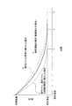
図7は、室内ファン140、室外ファン230、圧縮機240の回転作動を開始した場合に、室温の初期温度が設定温度まで到達する時間を示す図である。
本実施形態では、空気調和機1は、家屋から閾値以上離れていた対象となる人が、閾値よりも家屋に接近したときに、室内ファン140、室外ファン230、および/または圧縮機240の回転作動を開始し、最大能力の回転速度とする運転開始制御を行う。
図7の細鎖線aに示すように、通常運転の場合(機器が停止の場合(即ち本発明を実施しない場合))、室温の初期温度が設定温度まで到達する時間taは、最も長い。
図7の太鎖線bに示すように、室内機10の制御部110が、室内ファン140の回転作動を開始した場合(例えば室内ファン140の回転作動を開始し最大能力の回転速度とした場合)、室温の初期温度が設定温度まで到達する時間tbは、短縮される。
<Operation start control based on the rotational speed of the
FIG. 7 is a diagram illustrating a time for the initial temperature of the room temperature to reach the set temperature when the rotation operation of the
In the present embodiment, the
As shown by a thin chain line a in FIG. 7, in normal operation (when the device is stopped (that is, when the present invention is not performed)), the time ta when the initial temperature of the room temperature reaches the set temperature is the longest.
7, when the control unit 110 of the
図7の実線cに示すように、さらに、室外機20の制御部210が、制御部110と連携して、室内ファン140の回転作動の開始に加えて、室外ファン230、圧縮機240の回転作動を開始した場合(例えば室外ファン230、圧縮機240の回転作動を開始し最大能力の回転速度とした場合)、室温の初期温度が設定温度まで到達する時間tcは、最も短縮され、通常運転の場合に比べて約半減される。
このことから、室温の初期温度が設定温度までの温度差が大きい場合や、室温を設定温度に速やかに空調したい場合には、図7の実線cに示す室内ファン140、室外ファン230、および圧縮機240の回転作動を開始させることが有効である。機器の回転作動を開始させると、空気調和機1の騒音は増加するが、室内の場合は無人であるので、騒音は問題とならない(室内には騒音を気にする人が存在しない)。ただし、屋外に設置された室外ファン230、圧縮機240の回転速度が増加すると、近隣に対して騒音の影響が考えられる。しかしながら、室内ファン140、室外ファン230、圧縮機240の回転作動をいずれも開始させた場合、室温は上記設定温度までより速く到達するので、騒音の発生時間は短くなる。上記設定温度に達した後は、騒音の小さい通常運転に移行するか、または空気調和機1の運転は停止される。したがって、トータルでみた場合、近隣に対する騒音の発生時間は、短縮されるので、苦情等を招くおそれが少ないことが期待できる。
Further, as shown by a solid line c in FIG. 7, the
From this, when the temperature difference between the initial temperature of the room temperature and the set temperature is large, or when it is desired to quickly air-condition the room temperature to the set temperature, the
逆に、室温の初期温度が設定温度までの温度差が小さい場合には、室外ファン230、圧縮機240の回転作動を開始が可能な場合であっても、室外ファン230、圧縮機240の回転作動を開始は行わないようにすることも可能である。室外ファン230、圧縮機240の回転作動を開始を増加させなければ、近隣に対する騒音の影響は少ない。また、室内ファン140の回転作動を開始は、室内が無人であるので、騒音は問題とならない。なお、前記のように近隣の家屋の人の在/不在に応じて制御を行ってもよい。
On the contrary, when the temperature difference between the initial temperature of the room temperature and the set temperature is small, the rotation of the
図8は、空気調和機1の室内ファン140、室外ファン230、圧縮機240の回転速度による運転開始制御を示すフローチャートである。本フローは、図2のCPU等からなる制御部110において実行される。
空気調和機1の室内ファン140、室外ファン230、圧縮機240の回転速度による運転開始制御は、冷房時、暖房時のいずれにも適用される。冷房時の場合を例に採るが、暖房時の場合も同様に制御できる。
ステップS11で受信部120(図2参照)は、人接近を知らせる外部信号を受信する。
ステップS41で制御部110(図2参照)は、室内機10のセンサ部130(図2参照)の室内温度検出部132が測定した室内温度、および室外機20のセンサ部220(図2参照)の室外温度検出部221が測定した室外温度を検出する(測定信号を取り込む)。
ステップS13で制御部110は、検出した室内温度と設定温度との温度差が所定値以上かを判別する。
検出した室内温度と設定温度との温度差が所定設定値より小さい(温度差<所定設定値)場合(ステップS13:No)は、本フローの処理を終了する。
FIG. 8 is a flowchart showing the operation start control based on the rotation speeds of the
The operation start control based on the rotational speeds of the
In step S <b> 11, the receiving unit 120 (see FIG. 2) receives an external signal that notifies the approach of a person.
In step S41, the control unit 110 (see FIG. 2) determines the indoor temperature measured by the indoor
In step S13, the control unit 110 determines whether the detected temperature difference between the room temperature and the set temperature is equal to or greater than a predetermined value.
When the temperature difference between the detected room temperature and the set temperature is smaller than the predetermined set value (temperature difference <predetermined set value) (step S13: No), the process of this flow is terminated.
検出した室内温度と設定温度との温度差が所定設定値以上(温度差≧所定設定値)場合(ステップS13:Yes)、ステップS42に進む。
ステップS42で制御部110は、室内温度と室外温度との室内外温度差が室外ファン230、圧縮機240を回転作動させる設定値か否かを判別する。
室内外温度差が所定設定値以下(室内外温度差≦設定値)場合(ステップS42:No)は、室外ファン230、圧縮機240の回転作動を開始させて運転する必要がないと判断してステップS14に進む。
When the detected temperature difference between the room temperature and the set temperature is equal to or greater than the predetermined set value (temperature difference ≧ predetermined set value) (step S13: Yes), the process proceeds to step S42.
In step S <b> 42, the control unit 110 determines whether the indoor / outdoor temperature difference between the indoor temperature and the outdoor temperature is a set value for rotating the
When the indoor / outdoor temperature difference is equal to or smaller than the predetermined set value (indoor / outdoor temperature difference ≦ set value) (step S42: No), it is determined that it is not necessary to start the rotation operation of the
ステップS14で制御部110は、室内機10の室内ファン140(図2参照)を、使用者がリモコン30で設定できる室内ファン140の最大回転速度(図3参照)を超えた、最大能力の回転速度で運転する。具体的には、制御部110は、ファン回転速度設定部112に指令を送信して、室内ファン140の回転速度を最大能力に設定する。ファン回転速度設定部112にこの指令を受けて、室内ファン140を最大回転速度で運転する。
ただし、室内ファン140が、最大能力の回転速度で運転ができない仕様の空気調和機1の場合には、使用者がリモコン30で設定できる室内ファン140の最大回転速度で運転する。
In step S14, the control unit 110 rotates the maximum capacity of the indoor fan 140 (see FIG. 2) of the
However, when the
ステップS15で制御部110は、検出した室内温度があらかじめ設定された設定温度より高いか否かを判別する。
室内温度が設定温度以下(室内温度≦設定温度)場合(ステップS15:No)は、室内ファン140の回転速度を最大能力の回転速度で運転する必要がないと判断してステップS17に進む。
室内温度が設定温度より高い(室内温度>設定温度)場合(ステップS15:Yes)、ステップS16で制御部110は、室内に人を検知したか否かを判別する。
In step S15, the control unit 110 determines whether or not the detected room temperature is higher than a preset set temperature.
When the room temperature is equal to or lower than the set temperature (room temperature ≦ set temperature) (step S15: No), it is determined that it is not necessary to operate the
When the room temperature is higher than the set temperature (room temperature> set temperature) (step S15: Yes), in step S16, the control unit 110 determines whether a person is detected in the room.
室内に人を検知していない場合(ステップS16:No)、ステップS14に戻って、上記室内ファン140の回転速度の最大能力運転を継続する。
室内に人を検知した場合(ステップS16:Yes)、室内ファン140の騒音を低減する必要があると判断してステップS17に進む。
ステップS17で制御部110は、室内ファン140の回転速度を低減して本フローの処理を終了する。
When a person is not detected indoors (step S16: No), it returns to step S14 and continues the maximum capacity operation of the rotational speed of the
When a person is detected in the room (step S16: Yes), it is determined that the noise of the
In step S <b> 17, the control unit 110 reduces the rotation speed of the
一方、上記ステップS42において、室内温度と室外温度との室内外温度差が室外ファン230、圧縮機240を回転作動させる設定値より高い(室内外温度差>設定値)場合(ステップS42:Yes)は、室外ファン230、圧縮機240の回転速度を増加させて運転する必要があると判断してステップS43に進む。
ステップS43で制御部110は、室外機20の制御部210(図2参照)に、圧縮機240の回転速度を増加させる指令を発行し、制御部210は、これに応えて圧縮機240の回転速度を増加させる。
また、ステップS44で制御部110は、室外ファン230の回転速度を増加させる指令を発行し、制御部210は、これに応えて室外ファン230の回転速度を増加させる。
On the other hand, in step S42, when the indoor / outdoor temperature difference between the indoor temperature and the outdoor temperature is higher than the set value for rotating the
In step S43, the control unit 110 issues a command to increase the rotation speed of the
In step S44, the control unit 110 issues a command to increase the rotation speed of the
ステップS45で制御部110は、室内機10の室内ファン140を、使用者がリモコン30で設定できる室内ファン140の最大回転速度を超えた、最大能力の回転速度で運転する。ただし、室内ファン140が、最大能力の回転速度で運転ができない仕様の空気調和機1の場合には、使用者がリモコン30で設定できる室内ファン140の最大回転速度で運転する。
In step S <b> 45, the control unit 110 operates the
なお、本実施形態では、室内温度と室外温度との室内外温度差が室外ファン230、圧縮機240を回転作動させる設定値より高い場合、圧縮機240の回転速度と室外ファン230の回転作動をいずれも開始させているが、いずれか一方の回転作動を開始させる態様でもよい。
また、上記設定値を複数設け、室内外温度差に応じて、(1)室内機10の室内ファン140のみ、(2)室内機10の室内ファン140と圧縮機240の回転速度と室外ファン230の回転速度のいずれか一方、(3)室内ファン140、圧縮機240および室外ファン230の回転速度の回転作動を開始させる態様でもよい。
In the present embodiment, when the indoor / outdoor temperature difference between the indoor temperature and the outdoor temperature is higher than a set value for rotating the
Further, a plurality of the set values are provided, and (1) only the
室内温度が設定温度より高い(室内温度>設定温度)場合(ステップS46:Yes)、ステップS47で制御部110は、室内に人を検出したか否かを判別する。
室内に人を検知していない場合(ステップS47:No)、ステップS43に戻って、上記室内ファン140の回転速度の最大能力運転、圧縮機240および室外ファン230の回転速度の増加運転を継続する。
When the room temperature is higher than the set temperature (room temperature> set temperature) (step S46: Yes), in step S47, the control unit 110 determines whether a person is detected in the room.
When a person is not detected indoors (step S47: No), it returns to step S43 and continues the maximum capacity operation of the rotational speed of the
上記ステップS46で室内温度が設定温度以下(室内温度≦設定温度)場合(ステップS46:No)、または上記ステップS47で室内に人を検出した場合(ステップS47:Yes)、室内ファン140、圧縮機240および室外ファン230の騒音を低減する必要があると判断してステップS48に進む。
If the room temperature is equal to or lower than the set temperature in step S46 (room temperature ≦ set temperature) (step S46: No), or if a person is detected in the room in step S47 (step S47: Yes), the
ステップS48で制御部110は、室外ファン230の回転速度を低減させる指令を発行し、制御部210は、これに応えて室外ファン230の回転速度を低減させる。
ステップS49で制御部110は、室外機20の制御部210に、圧縮機240の回転速度を低減させる指令を発行し、制御部210は、これに応えて圧縮機240の回転速度を低減させる。
ステップS17で制御部110は、室内ファン140の回転速度を低減して本フローの処理を終了する。
なお、室内温度が設定温度に近い温度である場合等で、空気調和機1を起動させておく必要がない場合には、空気調和機1を停止させてもよい。
In step S48, the control unit 110 issues a command to reduce the rotational speed of the
In step S49, the control unit 110 issues a command to reduce the rotation speed of the
In step S <b> 17, the control unit 110 reduces the rotation speed of the
Note that the
以上説明したように、本実施形態に係る空気調和機1は、人接近を知らせる外部信号を受信する受信部120と、室内の温度を検出する室内温度検出部132と、室内と人との距離が所定閾値より近づいて、かつ、室内の温度と設定温度との温度差が所定以上の場合に、室内ファン140、圧縮機240、および/または、室外機20のうち少なくともいずれか一つの回転作動を開始する制御部110と、を備える。
制御部110は、室内と人との距離が所定閾値より近づいて、かつ、室内の温度と設定温度との温度差が所定以上の場合に、室内ファン140、圧縮機240、および/または、室外機20の回転速度を増加する。
As described above, the
When the distance between the room and the person is closer than a predetermined threshold and the temperature difference between the room temperature and the set temperature is greater than or equal to a predetermined value, the control unit 110 can control the
従来、空気調和機が最大能力で運転するとファンは最大回転速度で運転することになり、騒音も最大となる。ある程度部屋の温度が調整されるまでは最大能力の運転が続くため、騒音最大の状態が持続することになる。 Conventionally, when the air conditioner is operated at the maximum capacity, the fan is operated at the maximum rotation speed, and the noise is also maximized. The maximum capacity operation continues until the room temperature is adjusted to some extent, so that the maximum noise level is maintained.
本構成の空気調和機1は、使用者が外出して空気調和機が停止している際に、使用者が家屋(室内)から一定の閾値よりも近づくと、空気調和機1が使用者が設定できる最大以上の室内ファン140の回転速度、室外ファン230の回転速度、および/または、圧縮機240の回転速度で回転作動を開始する。これにより、人が室内にいない間に通常よりも大きな能力で空調することが可能になる。人が室内にいない室内をすばやく温調することで、人が帰宅した際に空気調和機が最大運転をする必要が無くなる。このため、人がいる際の空気調和機1の騒音を低減することができる。
In the
特に、制御部110は、室内ファン140が、使用者が設定できる最大回転速度を超えた、最大能力の回転速度で運転が可能である場合、室内と人との距離が所定閾値より近づいて、かつ、室内の温度と設定温度との温度差が所定以上の場合に、室内ファン140の最大能力の回転速度で運転する。
In particular, when the
この構成の場合、使用者が外出して帰宅する際、使用者が設定された閾値よりも家屋に近づいた際に室内ファン140や室外ファン230、圧縮機240を通常使用する最大回転速度を超える回転速度で運転する。これにより、使用者が家屋に到着する前に室内をすばやく温調することができ、帰宅時には室内が快適な環境となっている。なお、このときは空気調和機1の運転音が大きくなるが、室内には人がいないため問題とならない。
In the case of this configuration, when the user goes out and returns home, the maximum rotation speed at which the
本実施形態では、センサ部130が室内の人を検出し、制御部110は、無人で運転した後、在室を検出したときは、室内ファン140の回転速度を、少なくとも使用者が設定できる最大回転速度以下まで低減する。
室内に人が入ったことを検知すると通常回転速度での運転に切り替えることで、人がいる際に必要以上の騒音を発生し、使用者がうるさく感じることを防止できる。このとき、空気調和機1の温調(温度調節または空調)の能力は小さくなるが、既に大きな能力である程度の温調ができているため不快に感じることもない。なお、人を検出する前に室内温度が設定温度となった場合は、人を検出していなくても通常の運転に切り替えてもよい。
In the present embodiment, when the
When it is detected that a person has entered the room, it is possible to prevent the user from feeling noisy by generating more noise than necessary when the person is present by switching to driving at the normal rotation speed. At this time, the temperature adjustment (temperature adjustment or air conditioning) capability of the
本実施形態では、時計・カレンダー部111を備え、制御部110は、特定の日付、曜日や特定の時間には前述の機能を使用しないように設定してもよい。例えば、特定の曜日には帰宅途中に家屋近くの別の場所に用事があるような場合には、その曜日は本運転開始制御を実行しないように設定することで、長時間不在の場合に空調し続け、無駄な電力を使用することを防止できる。
In the present embodiment, the clock /
室外ファン230および圧縮機240の回転速度を通常の最大以上で運転すると、室外機20からの騒音が大きくなり、近隣からの苦情を招くおそれがある。そこで、本実施形態では、近隣の住宅の人の在/不在を検知する第4の検出手段を備え、近隣に人が不在の場合のみ、室外ファン10と圧縮機240の回転速度を最大以上で運転させるようにしてもよい。
When the rotational speeds of the
本実施形態では、制御部110は、室内の温度と設定温度との温度差に基づいて、室内ファン140の回転速度のみ、室内ファン140と圧縮機240の回転速度と室外ファン230の回転速度のいずれか一方、室内ファン140、圧縮機240および室外機20の回転作動を、選択的または段階的に開始させる。各回転速度を、選択的または段階的に開始することで、人が室内にいない室内をすばやく温調しつつ、人がいる際の空気調和機1の騒音と近隣への騒音低減の両立を図ることができる。より振動や騒音、異音の少なくかつ安定して運転できる空気調和機1を実現することができる。
In the present embodiment, the controller 110 determines only the rotational speed of the
本実施形態では、湿度検出部133を備え、制御部110は、湿度の検出値に基づいて、室内ファン140の回転速度を増加させて運転する温度優先モードと室内ファン140の回転速度を低速運転する除湿優先モードとを切り替える。これにより、室内機10の風量が大きい場合、除湿量は小さくなることに対応して、温度優先モードを選択することができる。
In the present embodiment, the
本発明は上記の実施形態例に限定されるものではなく、特許請求の範囲に記載した本発明の要旨を逸脱しない限りにおいて、他の変形例、応用例を含む。 The present invention is not limited to the above-described embodiments, and includes other modifications and application examples without departing from the gist of the present invention described in the claims.
上記した各実施形態例は本発明をわかりやすく説明するために詳細に説明したものであり、必ずしも説明した全ての構成を備えるものに限定されるものではない。また、ある実施形態例の構成の一部を他の実施形態例の構成に置き換えることが可能であり、また、ある実施形態例の構成に他の実施形態例の構成を加えることも可能である。また、各実施形態例の構成の一部について、他の構成の追加・削除・置換をすることが可能である。
例えば、本実施形態では、部屋(または家屋)とGPS機能等を有するスマートホン等を携帯した人との距離を求めて、距離に基づいて空調制御を行っているが、距離を時間に換算して上記のような空調制御を行ってもよい(距離と時間は等価である)。なお、距離は、直線距離でもよいが、マップマッチングして、地図上の道のりを距離としてもよい(当然、距離(道のり)を時間に換算した値を用いて制御してもよい)。いずれも、本発明の技術的範囲に属する。
Each of the above-described exemplary embodiments has been described in detail in order to explain the present invention in an easy-to-understand manner, and is not necessarily limited to one having all the configurations described. Further, a part of the configuration of an embodiment can be replaced with the configuration of another embodiment, and the configuration of another embodiment can be added to the configuration of an embodiment. . Further, it is possible to add, delete, and replace other configurations for a part of the configuration of each exemplary embodiment.
For example, in this embodiment, the distance between a room (or house) and a person carrying a smart phone having a GPS function or the like is obtained, and air conditioning control is performed based on the distance, but the distance is converted into time. The air conditioning control as described above may be performed (distance and time are equivalent). The distance may be a straight line distance, or may be a distance on a map by map matching (naturally, the distance (distance) may be controlled using a value converted into time). Both belong to the technical scope of the present invention.
1 空気調和機
10 室内機
20 室外機
30 リモコン
100 室内基板
110,220 制御部(制御手段)
111 時計・カレンダー部
112 ファン回転速度設定部
120 受信部(第1の検出手段,第4の検出手段)
130,220 センサ部(第3の検出手段)
131 撮像部(第3の検出手段)
132 室内温度検出部(第2の検出手段)
133 湿度検出部(第5の検出手段)
140 室内ファン(機器)
200 室外基板
211 ファン回転速度設定部
212 圧縮機回転速度設定部
221 室外温度検出部(第2の検出手段)
230 室外ファン(機器)
240 圧縮機(機器)
DESCRIPTION OF
111 Clock /
130, 220 sensor unit (third detection means)
131 Imaging unit (third detection means)
132 Indoor temperature detection part (2nd detection means)
133 Humidity detector (fifth detector)
140 Indoor fans (equipment)
200
230 Outdoor fan (equipment)
240 Compressor (Equipment)
Claims (5)
前記部屋の温度または外気の温度を検出する第2の検出手段と、
前記第1の検出手段と前記第2の検出手段の検出結果に基づいて空調の制御を行う制御手段とを備え、
前記制御手段は、
空調の停止時において、前記距離が設定距離よりも近づいて、かつ、前記部屋の温度または外気の温度と空調の設定温度との温度差が所定以上の場合に、室内機のファン、冷媒圧縮機、および、室外機のファンのうちの少なくとも1つの機器を回転作動させる空気調和機。 First detecting means for detecting a distance between a room to be air-conditioned or a house having the room and a person entering the room;
Second detection means for detecting the temperature of the room or the temperature of the outside air;
Control means for controlling air conditioning based on detection results of the first detection means and the second detection means;
The control means includes
When the air conditioning is stopped, when the distance is closer than the set distance and the temperature difference between the room temperature or the outside air temperature and the air conditioning set temperature is equal to or greater than a predetermined value, the fan of the indoor unit, the refrigerant compressor And an air conditioner that rotates at least one device of the fans of the outdoor unit.
前記室内機のファンを回転作動させる場合において、前記第3の検出手段が、人が前記部屋に入ったことを検出した際には前記室内機のファンを使用者が設定できる最大回転速度以下の回転速度で作動することを特徴とする請求項1に記載の空気調和機。 A third detecting means for detecting that a person is in the room;
In the case where the fan of the indoor unit is rotated, when the third detection unit detects that a person has entered the room, the fan of the indoor unit is not more than a maximum rotation speed that can be set by the user. The air conditioner according to claim 1, wherein the air conditioner operates at a rotational speed.
前記第4の検出手段が前記隣の家屋の人の不在を検出した場合は、前記室内機のファン、前記冷媒圧縮機、および、前記室外機のファンを、最大回転速度以上の回転速度で回転作動させることを特徴とする請求項1に記載の空気調和機。 A fourth detection means for detecting the presence / absence of a person in the house next to the house;
When the fourth detection means detects the absence of a person in the adjacent house, the fan of the indoor unit, the refrigerant compressor, and the fan of the outdoor unit are rotated at a rotation speed equal to or higher than the maximum rotation speed. The air conditioner according to claim 1, wherein the air conditioner is operated.
前記第5の検出手段が検出した湿度の検出値に応じて、前記室内機のファンの回転速度を最大回転速度以上の回転速度で回転作動する温度優先モードと前記室内機のファンの回転速度を低速で回転作動する除湿優先モードとを切り替えることを特徴とする請求項1に記載の空気調和機。 A fifth detecting means for detecting the humidity of the room;
The temperature priority mode in which the rotational speed of the fan of the indoor unit is rotated at a rotational speed equal to or higher than the maximum rotational speed and the rotational speed of the fan of the indoor unit according to the detected humidity value detected by the fifth detection means. The air conditioner according to claim 1, wherein the air conditioner is switched between a dehumidification priority mode that rotates at a low speed.
Priority Applications (2)
| Application Number | Priority Date | Filing Date | Title |
|---|---|---|---|
| JP2018094961A JP2019199994A (en) | 2018-05-16 | 2018-05-16 | Air conditioner |
| CN201810844391.3A CN110500732A (en) | 2018-05-16 | 2018-07-27 | Air conditioner |
Applications Claiming Priority (1)
| Application Number | Priority Date | Filing Date | Title |
|---|---|---|---|
| JP2018094961A JP2019199994A (en) | 2018-05-16 | 2018-05-16 | Air conditioner |
Publications (1)
| Publication Number | Publication Date |
|---|---|
| JP2019199994A true JP2019199994A (en) | 2019-11-21 |
Family
ID=68584215
Family Applications (1)
| Application Number | Title | Priority Date | Filing Date |
|---|---|---|---|
| JP2018094961A Pending JP2019199994A (en) | 2018-05-16 | 2018-05-16 | Air conditioner |
Country Status (2)
| Country | Link |
|---|---|
| JP (1) | JP2019199994A (en) |
| CN (1) | CN110500732A (en) |
Cited By (5)
| Publication number | Priority date | Publication date | Assignee | Title |
|---|---|---|---|---|
| CN112303849A (en) * | 2020-10-29 | 2021-02-02 | 青岛海尔空调电子有限公司 | Control method for reducing noise of air conditioner and air conditioner using same |
| CN113294886A (en) * | 2021-06-23 | 2021-08-24 | 宁波奥克斯电气股份有限公司 | Air conditioner noise reduction method and device and air conditioner |
| CN114413430A (en) * | 2021-09-13 | 2022-04-29 | Tcl空调器(中山)有限公司 | Air conditioner control method and device, air conditioner and storage medium |
| KR102430621B1 (en) * | 2021-11-16 | 2022-08-09 | 케빈랩 주식회사 | Controlling system and method for thermal comfort of room space |
| CN115854522A (en) * | 2022-11-28 | 2023-03-28 | 宁波奥克斯电气股份有限公司 | Air conditioner control method, control device, air conditioner and storage medium |
Families Citing this family (2)
| Publication number | Priority date | Publication date | Assignee | Title |
|---|---|---|---|---|
| CN111412614B (en) * | 2020-03-31 | 2022-03-01 | 广东美的制冷设备有限公司 | Vortex ring generation method based on air conditioner, storage medium and device |
| CN111706974B (en) * | 2020-06-05 | 2021-12-17 | 美的集团武汉暖通设备有限公司 | Control method of air conditioner, air conditioner and storage medium |
Citations (9)
| Publication number | Priority date | Publication date | Assignee | Title |
|---|---|---|---|---|
| JPH06249492A (en) * | 1993-02-26 | 1994-09-06 | Toshiba Corp | Air conditioning device |
| JP2011158170A (en) * | 2010-02-01 | 2011-08-18 | Panasonic Corp | Air-conditioner |
| JP2013200098A (en) * | 2012-03-26 | 2013-10-03 | Mitsubishi Electric Corp | Air conditioning device |
| JP2014153008A (en) * | 2013-02-12 | 2014-08-25 | Sharp Corp | Air conditioner |
| US20140309788A1 (en) * | 2013-04-11 | 2014-10-16 | Honeywell International Inc. | System and Method with GEO Location Triggering Automatic Action |
| JP2016008742A (en) * | 2014-06-23 | 2016-01-18 | パナソニックIpマネジメント株式会社 | Air conditioning device |
| WO2016157283A1 (en) * | 2015-03-27 | 2016-10-06 | 三菱電機株式会社 | Terminal apparatus, air conditioner, and wearable terminal |
| JP2017032156A (en) * | 2015-07-29 | 2017-02-09 | シャープ株式会社 | Air conditioner and control method |
| JP2017190880A (en) * | 2016-04-11 | 2017-10-19 | 三菱電機株式会社 | Control device, server, noise monitoring system, heat pump equipment and program |
Family Cites Families (1)
| Publication number | Priority date | Publication date | Assignee | Title |
|---|---|---|---|---|
| WO2012123989A1 (en) * | 2011-03-16 | 2012-09-20 | 三菱電機株式会社 | Air-conditioning system management device |
-
2018
- 2018-05-16 JP JP2018094961A patent/JP2019199994A/en active Pending
- 2018-07-27 CN CN201810844391.3A patent/CN110500732A/en active Pending
Patent Citations (9)
| Publication number | Priority date | Publication date | Assignee | Title |
|---|---|---|---|---|
| JPH06249492A (en) * | 1993-02-26 | 1994-09-06 | Toshiba Corp | Air conditioning device |
| JP2011158170A (en) * | 2010-02-01 | 2011-08-18 | Panasonic Corp | Air-conditioner |
| JP2013200098A (en) * | 2012-03-26 | 2013-10-03 | Mitsubishi Electric Corp | Air conditioning device |
| JP2014153008A (en) * | 2013-02-12 | 2014-08-25 | Sharp Corp | Air conditioner |
| US20140309788A1 (en) * | 2013-04-11 | 2014-10-16 | Honeywell International Inc. | System and Method with GEO Location Triggering Automatic Action |
| JP2016008742A (en) * | 2014-06-23 | 2016-01-18 | パナソニックIpマネジメント株式会社 | Air conditioning device |
| WO2016157283A1 (en) * | 2015-03-27 | 2016-10-06 | 三菱電機株式会社 | Terminal apparatus, air conditioner, and wearable terminal |
| JP2017032156A (en) * | 2015-07-29 | 2017-02-09 | シャープ株式会社 | Air conditioner and control method |
| JP2017190880A (en) * | 2016-04-11 | 2017-10-19 | 三菱電機株式会社 | Control device, server, noise monitoring system, heat pump equipment and program |
Cited By (7)
| Publication number | Priority date | Publication date | Assignee | Title |
|---|---|---|---|---|
| CN112303849A (en) * | 2020-10-29 | 2021-02-02 | 青岛海尔空调电子有限公司 | Control method for reducing noise of air conditioner and air conditioner using same |
| CN112303849B (en) * | 2020-10-29 | 2022-05-20 | 青岛海尔空调电子有限公司 | Control method for reducing noise of air conditioner and air conditioner using same |
| CN113294886A (en) * | 2021-06-23 | 2021-08-24 | 宁波奥克斯电气股份有限公司 | Air conditioner noise reduction method and device and air conditioner |
| CN114413430A (en) * | 2021-09-13 | 2022-04-29 | Tcl空调器(中山)有限公司 | Air conditioner control method and device, air conditioner and storage medium |
| CN114413430B (en) * | 2021-09-13 | 2023-01-20 | Tcl空调器(中山)有限公司 | Air conditioner control method and device, air conditioner and storage medium |
| KR102430621B1 (en) * | 2021-11-16 | 2022-08-09 | 케빈랩 주식회사 | Controlling system and method for thermal comfort of room space |
| CN115854522A (en) * | 2022-11-28 | 2023-03-28 | 宁波奥克斯电气股份有限公司 | Air conditioner control method, control device, air conditioner and storage medium |
Also Published As
| Publication number | Publication date |
|---|---|
| CN110500732A (en) | 2019-11-26 |
Similar Documents
| Publication | Publication Date | Title |
|---|---|---|
| JP2019199994A (en) | Air conditioner | |
| JP6052451B2 (en) | Air conditioning controller | |
| US11105885B2 (en) | System and methods for identifying the location of a device based on calibration information | |
| JP6091624B2 (en) | Air conditioning system | |
| JP6261295B2 (en) | Air conditioning system | |
| JP6125039B2 (en) | Air conditioning controller | |
| JP6722988B2 (en) | Air conditioner and control method | |
| JP2006245829A (en) | Apparatus, system, method and program for controlling electric appliance, and recording medium | |
| JPH0879840A (en) | Home control system | |
| JP6094698B2 (en) | Air conditioning controller | |
| JP2015078802A (en) | Indoor unit of air conditioning device and air conditioning device | |
| JP2013040713A (en) | Indoor environment conditioning system | |
| JP2004102653A (en) | Facility equipment, useful information generation system, portable terminal automatic restriction system, and portable terminal | |
| JP6169534B2 (en) | Message notification device, message notification method, message output device, message output system, portable device, automobile, air conditioning device, and program | |
| US11181292B2 (en) | Information output system, device control system, information output method, and program | |
| JP2011106763A (en) | Control system of air conditioner | |
| JP6804272B2 (en) | Air conditioner control device | |
| JP6636176B2 (en) | Remote controller and air conditioning system | |
| JP2016027303A (en) | Air conditioning system and air conditioner | |
| JP5821935B2 (en) | Air conditioning system | |
| JP6285815B2 (en) | Air conditioner or air conditioning system | |
| WO2018207237A1 (en) | Air conditioner and air conditioning system | |
| JP2017207254A (en) | Air Conditioning System | |
| JP6661798B2 (en) | Air conditioning system and air conditioning method | |
| JP7394992B2 (en) | Remote control equipment and air conditioning equipment |
Legal Events
| Date | Code | Title | Description |
|---|---|---|---|
| A621 | Written request for application examination |
Free format text: JAPANESE INTERMEDIATE CODE: A621 Effective date: 20190614 |
|
| A977 | Report on retrieval |
Free format text: JAPANESE INTERMEDIATE CODE: A971007 Effective date: 20200514 |
|
| A131 | Notification of reasons for refusal |
Free format text: JAPANESE INTERMEDIATE CODE: A131 Effective date: 20200609 |
|
| A02 | Decision of refusal |
Free format text: JAPANESE INTERMEDIATE CODE: A02 Effective date: 20201201 |