JP2017190880A - Control device, server, noise monitoring system, heat pump equipment and program - Google Patents
Control device, server, noise monitoring system, heat pump equipment and program Download PDFInfo
- Publication number
- JP2017190880A JP2017190880A JP2016078794A JP2016078794A JP2017190880A JP 2017190880 A JP2017190880 A JP 2017190880A JP 2016078794 A JP2016078794 A JP 2016078794A JP 2016078794 A JP2016078794 A JP 2016078794A JP 2017190880 A JP2017190880 A JP 2017190880A
- Authority
- JP
- Japan
- Prior art keywords
- frequency domain
- unit
- domain signal
- abnormality
- sound
- Prior art date
- Legal status (The legal status is an assumption and is not a legal conclusion. Google has not performed a legal analysis and makes no representation as to the accuracy of the status listed.)
- Granted
Links
Images


Landscapes
- Air Conditioning Control Device (AREA)
- Emergency Alarm Devices (AREA)
Abstract
【課題】室外機を備えるヒートポンプ機器において、室外機の騒音で近隣住民とのトラブルに発展することを防止する。【解決手段】制御装置1は、建屋10に設置されるヒートポンプ機器2の室外機21周辺の音を収音する騒音測定装置5が収音した収音信号を、室内機22を介して取得する。制御装置1は、収音信号を周波数ごとの信号レベルを表す周波数領域信号に変換し、ネットワーク6を介してクラウドサーバ3に送信する。クラウドサーバ3は、制御装置1から取得した周波数領域信号を記憶する。クラウドサーバ3は、制御装置1から取得した周波数領域信号と記憶している周波数領域信号との比較を行い、室外機21周辺の音に異常があるか否かを判定し、室外機21周辺の音に異常があると判定すると、室外機21周辺の音の異常を通知する警告情報を制御装置1に送信する。制御装置1は、クラウドサーバ3から受信した警告情報を出力する。【選択図】図1An object of the present invention is to prevent a heat pump device including an outdoor unit from developing into a trouble with neighboring residents due to the noise of the outdoor unit. A control device 1 acquires, via an indoor unit 22, a sound collection signal collected by a noise measuring device 5 that collects sound around an outdoor unit 21 of a heat pump device 2 installed in a building 10. . The control device 1 converts the collected sound signal into a frequency domain signal representing a signal level for each frequency, and transmits it to the cloud server 3 via the network 6. The cloud server 3 stores the frequency domain signal acquired from the control device 1. The cloud server 3 compares the frequency domain signal acquired from the control device 1 with the stored frequency domain signal, determines whether there is an abnormality in the sound around the outdoor unit 21, and When it is determined that the sound is abnormal, warning information for notifying the abnormality of the sound around the outdoor unit 21 is transmitted to the control device 1. The control device 1 outputs the warning information received from the cloud server 3. [Selection] Figure 1
Description
本発明は、ヒートポンプ機器の室外機の騒音を監視する制御装置、サーバ、騒音監視システム、ヒートポンプ機器およびプログラムに関する。 The present invention relates to a control device, a server, a noise monitoring system, a heat pump device, and a program for monitoring the noise of an outdoor unit of a heat pump device.
人口の都市部への集中化に伴い、各家庭からの騒音が近隣住民とのトラブルを引き起こす事例が増加している中で、給湯機や空調機などの室外機が発する低周波が苦情となる事例が多く報告されている。騒音トラブルの予防策として、屋内で一定以上の音量の騒音を検知した場合に、それを報知するシステムが提案されている。 As the population is concentrated in urban areas, there is an increasing number of cases where noise from households causes troubles with neighboring residents. Low frequencies generated by outdoor units such as water heaters and air conditioners are becoming complaints. Many cases have been reported. As a preventive measure for noise troubles, a system has been proposed that notifies when a noise of a certain level or higher is detected indoors.
例えば、特許文献1には、隣接する各住戸の住人が設定した騒音の希望閾値のうち、最小の閾値を超える騒音を発している場合に騒音発生を報知したり、騒音源となっている機器の音量を下げたりする騒音検知システムが開示されている。
For example, in
特許文献2には、周囲の住戸の人の在否や、周囲の住戸で発している騒音レベルに応じて警告表示を行う閾値が設定される騒音警告システムが開示されている。
しかしながら、特許文献1および特許文献2に記載の技術は、屋内で検知した音の音量が閾値以上であるか否かで騒音が発生しているか否かを判定し、騒音の発生を報知する、あるいは音量制御可能な機器の騒音低減を図るのみであり、給湯機や空調機などの室外機の騒音を検知するものではない。また、給湯機や空調機などのヒートポンプ機器の室外機の騒音は、ユーザ自身よりも近隣住民に対する迷惑となる場合が多く、近隣住民とのトラブルに発展する可能性が大きくなるという問題がある。騒音低減のためには、ユーザがヒートポンプ機器の点検修理サービスを提供するサービスセンターに連絡する手間が必要である。
However, the techniques described in
室外機の騒音はユーザ自身よりも近隣住民に対する迷惑となる場合が多く、サービスセンターに連絡する手間がかかることや、騒音源が屋外にあるためユーザがクレームとなるレベルの騒音の発生に気づかないことから、ユーザがサービスセンターへの連絡を行わず、近隣住民とのトラブルに発展する可能性が大きくなるという問題がある。また、人が不愉快に感じる騒音は周波数によって異なるので、音量のみでヒートポンプ機器の騒音判定を行うと、騒音と判定されないにもかかわらず、近隣住民からのクレームとなる場合がある。 Outdoor unit noise is often more annoying to neighboring residents than the user himself, and it takes time to contact the service center and the user is unaware of the level of noise that is claimed by the user because the noise source is outdoors. For this reason, there is a problem that the possibility that the user will not contact the service center and develop into troubles with neighboring residents increases. In addition, since the noise that people feel unpleasant varies depending on the frequency, if the noise determination of the heat pump device is performed based only on the volume, there may be a complaint from a neighboring resident even though the noise is not determined.
本発明は、上述のような事情に鑑みてなされたもので、室外機を備えるヒートポンプ機器において、室外機の騒音で近隣住民とのトラブルに発展することを防止することを目的とする。 The present invention has been made in view of the above-described circumstances, and an object of the present invention is to prevent a heat pump device including an outdoor unit from developing into trouble with neighboring residents due to the noise of the outdoor unit.
上記目的を達成するため、本発明に係る制御装置は、建屋に設置される室外機および室内機を含むヒートポンプ機器の室外機周辺の音を収音する騒音測定装置、ならびに、建屋外部のネットワークに接続されたサーバと接続される。制御装置は、収音信号取得部と、周波数領域変換部と、周波数領域信号送信部と、警告情報受信部と、警告情報出力部とを備える。収音信号取得部は、騒音測定装置が収音した収音信号を取得する。周波数領域変換部は、収音信号を周波数ごとの信号レベルを表す周波数領域信号に変換する。周波数領域信号送信部は、周波数領域信号をサーバに送信する。警告情報受信部は、サーバから、周波数領域信号に基づいて判定された室外機周辺の音の異常を通知する警告情報を受信する。警告情報出力部は、警告情報受信部が受信した警告情報を出力する。 In order to achieve the above object, a control device according to the present invention is installed in an outdoor unit installed in a building and a noise measuring device that collects sound around the outdoor unit of a heat pump device including the indoor unit, and a network in an outdoor part of the building. Connected to the connected server. The control device includes a collected sound signal acquisition unit, a frequency domain conversion unit, a frequency domain signal transmission unit, a warning information reception unit, and a warning information output unit. The collected sound signal acquisition unit acquires a collected sound signal collected by the noise measurement device. The frequency domain conversion unit converts the collected sound signal into a frequency domain signal representing a signal level for each frequency. The frequency domain signal transmission unit transmits the frequency domain signal to the server. The warning information receiving unit receives warning information for notifying abnormality of sound around the outdoor unit determined based on the frequency domain signal from the server. The warning information output unit outputs the warning information received by the warning information receiving unit.
本発明によれば、ヒートポンプ機器が備える室外機周辺の音を収音し、収音した音の周波数ごとの信号レベルに基づいて、室外機周辺の音に異常があると判定された場合に、室外機周辺の音に異常があることを通知する警告情報を出力することで、室外機の騒音で近隣住民とのトラブルに発展することを防止することができる。 According to the present invention, the sound around the outdoor unit provided in the heat pump device is collected, and when it is determined that the sound around the outdoor unit is abnormal based on the signal level for each frequency of the collected sound, By outputting warning information notifying that there is an abnormality in the sound around the outdoor unit, it is possible to prevent the noise from the outdoor unit from developing into a trouble with neighboring residents.
以下に、本発明を実施するための形態について図面を参照して詳細に説明する。なお、図中同一または相当する部分には同じ符号を付す。本実施の形態では、制御装置に接続するサーバがクラウドサーバである例について説明する。 EMBODIMENT OF THE INVENTION Below, the form for implementing this invention is demonstrated in detail with reference to drawings. In addition, the same code | symbol is attached | subjected to the part which is the same or it corresponds in a figure. In the present embodiment, an example in which the server connected to the control device is a cloud server will be described.
(実施の形態1)
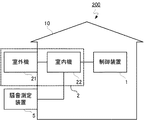
図1は、本発明の実施の形態1に係る騒音管理システムの構成例を示す図である。騒音管理システム100は、制御装置1と、ヒートポンプ機器2と、騒音測定装置5と、クラウドサーバ3とで構成される。ヒートポンプ機器2は、空調機や給湯機といったヒートポンプ機器であり、室外機21および室内機22とで構成される。制御装置1は、室内機22に接続し、建屋10の外部のネットワーク6を介してクラウドサーバ3に接続する。建屋10は、居住用家屋、店舗および工場などを含む。クラウドサーバ3は、ネットワーク6を介して制御装置1およびサービスセンターサーバ4に接続する。サービスセンターサーバ4は、ヒートポンプ機器2の点検修理サービスを提供するサービスセンターが管理するサーバである。ネットワーク6は、インターネットのような外部と接続するネットワークである。図1では、建屋10は代表して1つ記載しているが、これに限らず、建屋10は2以上であってもよい。この場合、複数の建屋10がそれぞれ備える制御装置1は、ネットワーク6を介してクラウドサーバ3に接続する。
(Embodiment 1)
FIG. 1 is a diagram illustrating a configuration example of a noise management system according to
騒音測定装置5は、例えばマイクロフォンのような音を収音できるセンサであり、室外機21周辺の音を収音する。騒音測定装置5が収音した収音信号は例えば音圧(単位dB)を示す。騒音測定装置5は、室外機21に内蔵されてもよい。室内機22は、騒音測定装置5から収音信号を取得し、記憶する。制御装置1は、決められたタイミングで収音信号を要求する要求信号を室内機22に送り、室内機22はこれに応答して収音信号を制御装置1に送る。あるいは、制御装置1は、騒音測定装置5に接続し、騒音測定装置5から収音信号を取得してもよい。
The noise measuring
制御装置1は、例えば、HEMS(Home Energy Management System)コントローラであり、室内機22から取得した収音信号を周波数ごとの信号レベル(音圧レベル)を表す周波数領域信号に変換してクラウドサーバ3に送信する。HEMSコントローラとは、一般的に家庭内の各種ヒートポンプ機器と無線あるいは有線による宅内ネットワークで接続し、各ヒートポンプ機器の電力消費量や運転状態を取得して見える化を実現するとともに、各ヒートポンプ機器の電源のON−OFFや運転モードの切り替えなどの制御を可能にするHEMSのコントローラである。制御装置1は、周波数領域信号の他にも、HEMSで収集されるヒートポンプ機器2の稼働状況、建屋10の周辺の騒音状況、およびヒートポンプ機器2の点検修理の実施状況のうち少なくともいずれかを示すヒートポンプ機器状況をクラウドサーバ3に送信する構成にしてもよい。ヒートポンプ機器状況は、さらにヒートポンプ機器2の故障の詳細や建屋10の近隣住民からのクレームの履歴などを含んでもよい。
The
クラウドサーバ3は、制御装置1から受信した周波数領域信号を記憶する。複数の建屋10がある場合には、クラウドサーバ3は、複数の建屋10の制御装置1からそれぞれ受信した周波数領域信号を建屋10ごとに記憶する。クラウドサーバ3は、制御装置1から受信した周波数領域信号と、蓄積された周波数領域信号との比較を行い、室外機21周辺の音の異常の有無を判定する。周波数領域信号が記憶される前は、初期値との比較を行い、室外機21周辺の音の異常の有無を判定する。クラウドサーバ3が制御装置1からヒートポンプ機器状況を受信する場合は、制御装置1から受信した周波数領域信号と、蓄積された周波数領域信号とに加えて、制御装置1から受信したヒートポンプ機器状況を用いて、室外機21周辺の音の異常の有無を判定する。クラウドサーバ3は、室外機21周辺の音に異常ありと判定した場合は、制御装置1と、サービスセンターサーバ4とに、室外機21周辺の音の異常を通知する警告情報を送信する。制御装置1は、クラウドサーバ3から受信した警告情報を出力する。
The
サービスセンターサーバ4は、クラウドサーバ3から警告情報を受信すると、音に異常が発生している室外機21の周波数領域信号や、室外機21周辺の音に異常が発生している建屋10のヒートポンプ機器状況を取得し、これに基づいて、ヒートポンプ機器2の点検修理が必要か否かを判断する。また、サービスセンターに届いた建屋10の近隣住民からのクレームの履歴をサービスセンターサーバ4が記憶している場合には、これを加味してもよい。室外機21の周波数領域信号や建屋10のヒートポンプ機器状況は、クラウドサーバ3から取得してもよいし、制御装置1から取得してもよい。サービスセンターサーバ4は、ヒートポンプ機器2の点検修理が必要と判断した場合、ヒートポンプ機器2の点検修理を提案する提案情報を、制御装置1に送信する。あるいは、サービスセンターの担当者が、ヒートポンプ機器2のユーザに電話や書簡でヒートポンプ機器2の点検修理を提案してもよいし、作業者が建屋10を訪問して室外機21の点検修理を行うようにしてもよい。これにより、建屋10の周辺住民からのクレームとなる前に、室外機21の騒音に対して対応することが可能となる。
When the
提案情報は、電話や書簡に加え、HEMSを利用して、建屋10内のユーザが使用するスマートフォンやタブレット、PCなどのユーザ端末に画面表示させたり、プッシュ通知したり、自動メールで送信したりすることも可能である。HEMSの仕組みを活用することで、電話や書簡でユーザと連絡が取りにくい場合でも、迅速に通知することが可能となる。なお、クラウドサーバ3は制御装置1に警告情報を送信せず、サービスセンターサーバ4が、点検修理が必要と判断した場合に、サービスセンターサーバ4が制御装置1に警告情報を送信する構成にしてもよい。
Proposal information can be displayed on a user terminal such as a smartphone, tablet, or PC used by users in the
図2は、実施の形態1に係る制御装置の機能構成例を示す図である。制御装置1は、収音信号取得部11と、周波数領域変換部12と、周波数領域信号送信部13と、警告情報受信部14と、警告情報出力部15とを備える。収音信号取得部11は、室内機22から収音信号を取得し、周波数領域変換部12に送る。室内機22から取得する収音信号は、制御装置1の要求信号を送信する周期(例えば30秒周期)に合わせて、その周期内の平均値としてもよいし、要求信号を送信したタイミングの瞬時値としてもよい。周波数領域変換部12は、収音信号取得部11から受け取った収音信号を周波数領域信号に変換し、周波数領域信号送信部13に送る。周波数領域信号は、例えば、収音信号をフーリエ変換して得られる周波数スペクトルであり、周波数ごとの信号レベルを示すテーブルである。周波数領域信号送信部13は、周波数領域変換部12から受け取った周波数領域信号をクラウドサーバ3に送信する。なお、周波数領域変換部12は、室内機22が備えてもよい。この場合、制御装置1は室内機22から周波数領域信号を取得し、クラウドサーバ3に送信する。
FIG. 2 is a diagram illustrating a functional configuration example of the control device according to the first embodiment. The
警告情報受信部14は、クラウドサーバ3から警告情報を受信し、警告情報出力部15に送る。警告情報出力部15は、警告情報受信部14から受け取った警告情報を出力する。警告情報の出力方法は、画面表示や音声出力でもよいし、HEMSを利用して、建屋10内のユーザ端末に送信してもよい。あるいは、室内機22が画面表示や音声出力機能を備える場合には、警告情報を室内機22に送って画面表示や音声出力させてもよい。また、クラウドサーバ3はサービスセンターサーバ4に警告情報を送信せず、警告情報出力部15がサービスセンターサーバ4に警告情報を送信する構成にしてもよい。
The warning
図3は、実施の形態1に係るクラウドサーバの機能構成例を示す図である。クラウドサーバ3は、周波数領域信号取得部31と、周波数領域信号記憶部32と、異常判定部33と、警告情報送信部34とを備える。周波数領域信号取得部31は、制御装置1から周波数領域信号を取得すると、異常判定部33に送り、周波数領域信号記憶部32に記憶する。異常判定部33は、周波数領域信号取得部31から受け取った周波数領域信号と周波数領域信号記憶部32が記憶している周波数領域信号との比較を行い、室外機21周辺の音に異常があるか否かを判定する。周波数領域信号が周波数領域信号記憶部32に記憶される前は、周波数領域信号記憶部32が記憶する初期値との比較を行い、室外機21周辺の音の異常の有無を判定する。
FIG. 3 is a diagram illustrating a functional configuration example of the cloud server according to the first embodiment. The
室外機21周辺の音の異常の有無の判定は、例えば、周波数領域信号に基づいて、信号レベルが閾値以上の周波数帯域があるか否かを判定し、閾値以上の周波数帯域がある場合、信号レベルが決められた閾値以上の周波数帯域を特定する。信号レベルが閾値以上の周波数帯域が予め決められた低周波帯に含まれるか否かを判定し、低周波帯に含まれる場合、低周波帯に含まれる周波数領域信号の信号レベルが閾値以上となっている状態が予め決められた判定時間以上継続しているか否かを判定する。信号レベルが閾値以上の周波数帯域が予め決められた低周波帯に含まれるか否かを判定するのは、クレームとなる可能性が高い騒音は低周波帯の音であるからである。予め決められた低周波帯の音の信号レベルが閾値以上となっている状態が判定時間以上継続している場合、室外機21周辺の音に異常があると判定する。信号レベル判定に用いられる閾値、周波数帯域判定に用いられる低周波帯、および、継続判定に用いられる判定時間は、判定データとして周波数領域信号記憶部32が記憶する。
For example, whether there is an abnormality in the sound around the
判定データは、初期値が設定されており、周波数領域信号記憶部32に周波数領域信号が記憶された後は、周波数領域信号記憶部32が記憶する過去の周波数領域信号から算出される。判定データの初期値は、ヒートポンプ機器2にあらかじめ設定されており、制御装置1がヒートポンプ機器2から取得する構成にしてもよいし、制御装置1にあらかじめ設定されていてもよい。周波数領域信号記憶部32は、初期値に加えて、周波数領域信号取得部31が制御装置1から周波数領域信号を取得する度に、または、決められた期間ごとに取得した周波数領域信号を記憶する。信号レベル判定に用いられる閾値は、初期値の他に、例えば、過去の周波数領域信号の信号レベルの平均値や、過去に異常と判定された周波数領域信号の信号レベルの最低値である。周波数帯域判定に用いられる低周波帯は、初期値の他に、例えば、過去にクレームになった場合において、閾値以上の信号レベルとなった周波数帯域の最高値以下の低周波帯や、過去に異常と判定された周波数領域信号の周波数帯域の最高値以下の低周波帯である。継続判定に用いられる判定時間は、初期値の他に、例えば、過去の低周波帯に含まれる周波数領域信号の信号レベルが閾値以上となっている状態が継続した時間の平均値や、過去にクレームになった場合の周波数領域信号の信号レベルが決められた閾値以上となっている状態が継続した時間の最小値である。このようにすることで、初期値との比較では検出できない室外機21の変調や、室外機21が設置された地域および位置による事情を考慮することができる。
The determination data is set to an initial value. After the frequency domain signal is stored in the frequency domain
クラウドサーバ3は、制御装置1からヒートポンプ機器状況を取得するヒートポンプ機器状況取得部を備えてもよい。この場合、異常判定部33は、周波数領域信号取得部31が取得した周波数領域信号と、周波数領域信号記憶部32が記憶する周波数領域信号とに加えて、ヒートポンプ機器状況取得部が取得したヒートポンプ機器状況を用いて、室外機21周辺の音の異常の有無を判定する。異常判定部33は、室外機21周辺の音に異常があると判定すると、室外機21周辺の音に異常があることを通知する警告情報を警告情報送信部34に送る。警告情報送信部34は、異常判定部33から受け取った警告情報を制御装置1およびサービスセンターサーバ4に送信する。なお、警告情報送信部34は、制御装置1にのみ警告情報を送信してもよいし、サービスセンターサーバ4にのみ警告情報を送信してもよい。ここで、図4を用いて騒音管理システム100の各装置が行う処理について説明する。
The
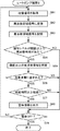
図4は、実施の形態1に係る騒音管理システムの動作の一例を示すフローチャートである。以下の処理は、騒音管理システム100を構成する各装置が起動すると開始する。ヒートポンプ機器2の室内機22は、騒音測定装置5から室外機21周辺の音を収音した収音信号を取得する(ステップS11)。室内機22は、騒音測定装置5から取得した収音信号を記憶する(ステップS12)。制御装置1の収音信号取得部11は、決められたタイミングで収音信号を要求する要求信号を室内機22に送信する(ステップS21)。室内機22が制御装置1から要求信号を受信しない場合(ステップS13;NO)、処理はステップS15に移行する。室内機22が制御装置1から要求信号を受信した場合(ステップS13;YES)、室内機22は、これに応答して収音信号を制御装置1に送信する(ステップS14)。ヒートポンプ機器2の電源がOFFになっていなければ(ステップS15;NO)、処理はステップS11に戻り、ステップS11〜ステップS15を繰り返す。ヒートポンプ機器2の電源がOFFになると(ステップS15;YES)、処理を終了する。
FIG. 4 is a flowchart showing an example of the operation of the noise management system according to the first embodiment. The following process starts when each device constituting the
制御装置1の収音信号取得部11は、室内機22から収音信号を受信し(ステップS22)、周波数領域変換部12に送る。周波数領域変換部12は、収音信号取得部11から受け取った収音信号を周波数領域信号に変換し(ステップS23)、周波数領域信号送信部13に送る。周波数領域信号送信部13は、周波数領域変換部12から受け取った周波数領域信号をクラウドサーバ3に送信する(ステップS24)。このとき、周波数領域信号送信部13は、クラウドサーバ3へのアップロード用データに変換して送信する。アップロード用データへの変換は、ネットワーク6の通信に必要なデータ整形、セキュリティに必要な暗号化処理などを含む。制御装置1がヒートポンプ機器状況をクラウドサーバ3に送信する構成の場合は、ヒートポンプ機器状況と合わせてアップロード用データへの変換がなされる。ここで、周波数領域信号送信部13は、例えばヒートポンプ機器2の電源がOFFの間(あるいはその前後)のデータを無効データとしてもよいし、室外機21あるいはヒートポンプ機器2自体に何らかの異常や故障が発生している時のデータを無効データとしてもよい。
The sound collection
クラウドサーバ3の周波数領域信号取得部31は、制御装置1から周波数領域信号を受信すると(ステップS31)、異常判定部33に送り、周波数領域信号記憶部32に記憶する(ステップS32)。クラウドサーバ3の周波数領域信号取得部31は、ステップS31で制御装置1から周波数領域信号を受信する度に判定データを更新してもよいし、または、決められた期間ごとに更新してもよい。異常判定部33は、周波数領域信号取得部31から受け取った周波数領域信号に基づいて、信号レベルが閾値以上の周波数帯域があるか否かを判定する(ステップS33)。閾値以上の周波数帯域がない場合(ステップS33;NO)、処理はステップS38に移行する。閾値以上の周波数帯域がある場合(ステップS33;YES)、異常判定部33は、信号レベルが閾値以上の周波数帯域を特定する(ステップS34)。
When the frequency domain
異常判定部33は、信号レベルが閾値以上の周波数帯域が予め決められた低周波帯に含まれるか否かを判定する(ステップS35)。低周波帯に含まれない場合(ステップS35;NO)、処理はステップS38に移行する。低周波帯に含まれる場合(ステップS35;YES)、異常判定部33は、信号レベルが閾値以上となっている状態が判定時間以上継続しているか否かを判定する(ステップS36)。判定時間以上継続していない場合(ステップS36;NO)、処理はステップS38に移行する。判定時間以上継続している場合(ステップS36;YES)、異常判定部33は、室外機21周辺の音に異常があると判定し、室外機21周辺の音に異常があることを通知する警告情報を警告情報送信部34に送る。警告情報送信部34は、異常判定部33から受け取った警告情報を制御装置1およびサービスセンターサーバ4に送信する(ステップS37)。クラウドサーバ3の電源がOFFになっていなければ(ステップS38;NO)、処理はステップS31に戻り、ステップS31〜ステップS38を繰り返す。クラウドサーバ3の電源がOFFになると(ステップS38;YES)、処理を終了する。
The
サービスセンターサーバ4では、クラウドサーバ3から警告情報を受信すると、音に異常が発生している室外機21の周波数領域信号と、室外機21周辺の音に異常が発生している建屋10のヒートポンプ機器状況とに基づいて、ヒートポンプ機器2の点検修理が必要か否かを判断する。ヒートポンプ機器2の点検修理が必要か否かの判断は、サービスセンターサーバ4が記憶する判断基準に従って自動で行ってもよいし、担当者が判断してサービスセンターサーバ4に入力してもよい。サービスセンターサーバ4は、ヒートポンプ機器2の点検修理が必要と判断した場合、ヒートポンプ機器2の点検修理を提案する提案情報を、室外機21周辺の音に異常が発生している建屋10の制御装置1に送信する。サービスセンターサーバ4は、提案が実施されたか否かを示す情報やヒートポンプ機器2の点検修理が必要か否かの判断基準となった情報をクラウドサーバ3にフィードバックしてもよい。
When the
制御装置1の警告情報受信部14がクラウドサーバ3から警告情報を受信しない場合(ステップS25;NO)、処理はステップS27に移行する。警告情報受信部14は、クラウドサーバ3から警告情報を受信すると(ステップS25;YES)、警告情報出力部15に送る。警告情報出力部15は、警告情報受信部14から受け取った警告情報を出力する(ステップS26)。制御装置1の電源がOFFになっていなければ(ステップS27;NO)、処理はステップS21に戻り、ステップS21〜ステップS27を繰り返す。制御装置1の電源がOFFになると(ステップS27;YES)、処理を終了する。
When the warning
以上説明したように実施の形態1の騒音管理システム100によれば、ヒートポンプ機器2が備える室外機21周辺の音を収音し、収音した音の周波数ごとの信号レベルに基づいて、室外機21周辺の音に異常があると判定した場合に、室外機21周辺の音に異常があることを通知する警告情報を出力することで、室外機21の騒音で近隣住民とのトラブルに発展することを防止することができる。また、ユーザが室外機21周辺の音に異常があることに気づかず放置することによって室外機21が故障することを防止することができる。さらに、サービスセンターサーバ4に自動的に警告情報を送信することで、ユーザがサービスセンターサーバ4に連絡する手間を省くことができる。
As described above, according to the
サービスセンターサーバ4からフィードバックされた情報やHEMSで収集されるヒートポンプ機器状況をクラウドサーバ3で継続的に蓄積して解析し、判定データに反映することで、判定データの精度を向上させることができる。また、騒音管理システム100を構成する建屋10が多いほど、クラウドサーバ3に蓄積されるサービスセンターサーバ4からフィードバックされた情報や制御装置1から取得したヒートポンプ機器状況が増え、ヒートポンプ機器2の機種別の傾向、地域別の傾向なども加味して、判定データの精度を向上させることができる。
The information fed back from the
(実施の形態2)
実施の形態2では、周波数領域信号を制御装置1内に蓄積し、制御装置1が室外機21周辺の音の異常の有無を判定する。
(Embodiment 2)
In the second embodiment, the frequency domain signal is accumulated in the
図5は、本発明の実施の形態2に係る騒音管理システムの構成例を示す図である。騒音管理システム200は、制御装置1と、ヒートポンプ機器2と、騒音測定装置5とで構成される。ヒートポンプ機器2および騒音測定装置5の構成は実施の形態1と同様である。制御装置1は、室内機22から収音信号を取得する。制御装置1は、室内機22から取得した収音信号を周波数領域信号に変換して記憶する。制御装置1は、変換した周波数領域信号と、蓄積された周波数領域信号との比較を行い、室外機21周辺の音の異常の有無を判定する。制御装置1は、室内機22から取得した収音信号を変換した周波数領域信号と、蓄積された周波数領域信号とに加えて、HEMSで収集されるヒートポンプ機器状況を用いて、室外機21周辺の音の異常の有無を判定してもよい。制御装置1は、室外機21周辺の音に異常ありと判定した場合は、室外機21周辺の音の異常を通知する警告情報を出力する。
FIG. 5 is a diagram showing a configuration example of a noise management system according to
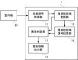
図6は、実施の形態2に係る制御装置の機能構成例を示す図である。制御装置1は、収音信号取得部11と、周波数領域変換部12と、周波数領域信号記憶部16と、異常判定部17と、警告情報出力部15とを備える。収音信号取得部11は、室内機22から収音信号を取得し、周波数領域変換部12に送る。周波数領域変換部12は、収音信号取得部11から受け取った収音信号を周波数領域信号に変換して周波数領域信号記憶部16に記憶し、異常判定部17に送る。異常判定部17は、周波数領域変換部12から受け取った周波数領域信号と周波数領域信号記憶部16が記憶している周波数領域信号との比較を行い、室外機21周辺の音に異常があるか否かを判定する。制御装置1の周波数領域信号記憶部16は、HEMSで収集されるヒートポンプ機器状況を記憶してもよい。この場合、異常判定部17は、周波数領域変換部12から受け取った周波数領域信号と周波数領域信号記憶部16が記憶している周波数領域信号とに加えて、周波数領域信号記憶部16が記憶しているヒートポンプ機器状況を用いて、室外機21周辺の音の異常の有無を判定する。異常判定部17は、室外機21周辺の音に異常があると判定すると、室外機21周辺の音に異常があることを通知する警告情報を警告情報出力部15に送る。警告情報出力部15は、異常判定部17から受け取った警告情報を出力する。警告情報の出力方法は、画面表示や音声出力でもよいし、HEMSを利用して、建屋10内のユーザ端末に送信してもよい。あるいは、室内機22が画面表示や音声出力機能を備える場合には、警告情報を室内機22に送って画面表示や音声出力させてもよいし、サービスセンターサーバ4に接続して警告情報を送信してもよい。ここで、図7を用いてヒートポンプ機器2が行う処理について説明する。
FIG. 6 is a diagram illustrating a functional configuration example of the control device according to the second embodiment. The
図7は、実施の形態2に係る騒音管理システムの動作の一例を示すフローチャートである。以下の処理は、騒音管理システム200を構成する各装置が起動すると開始する。ヒートポンプ機器2の室内機22は、騒音測定装置5から室外機21周辺の音を収音した収音信号を取得する(ステップS41)。室内機22は、騒音測定装置5から取得した収音信号を記憶する(ステップS42)。制御装置1の収音信号取得部11は、決められたタイミングで収音信号を要求する要求信号を室内機22に送信する(ステップS51)。室内機22が制御装置1から要求信号を受信しない場合(ステップS43;NO)、処理はステップS45に移行する。室内機22が制御装置1から要求信号を受信した場合(ステップS43;YES)、室内機22は、これに応答して収音信号を制御装置1に送信する(ステップS44)。ヒートポンプ機器2の電源がOFFになっていなければ(ステップS45;NO)、処理はステップS41に戻り、ステップS41〜ステップS45を繰り返す。ヒートポンプ機器2の電源がOFFになると(ステップS45;YES)、処理を終了する。
FIG. 7 is a flowchart showing an example of the operation of the noise management system according to the second embodiment. The following process starts when each device constituting the
制御装置1の収音信号取得部11は、室内機22から収音信号を受信し(ステップS52)、周波数領域変換部12に送る。周波数領域変換部12は、収音信号取得部11から受け取った収音信号を周波数領域信号に変換し(ステップS53)、周波数領域信号記憶部16に記憶する(ステップS54)。また、周波数領域変換部12は、変換した周波数領域信号を異常判定部17に送る。異常判定部17は、周波数領域変換部12から受け取った周波数領域信号に基づいて、信号レベルが閾値以上の周波数帯域があるか否かを判定する(ステップS55)。
The sound collection
閾値以上の周波数帯域がない場合(ステップS55;NO)、処理はステップS60に移行する。閾値以上の周波数帯域がある場合(ステップS55;YES)、異常判定部17は、信号レベルが決められた閾値以上の周波数帯域を特定する(ステップS56)。異常判定部17は、信号レベルが閾値以上の周波数帯域が予め決められた低周波帯に含まれるか否かを判定する(ステップS57)。低周波帯に含まれない場合(ステップS57;NO)、処理はステップS60に移行する。低周波帯に含まれる場合(ステップS57;YES)、異常判定部17は、信号レベルが閾値以上となっている状態が判定時間以上継続しているか否かを判定する(ステップS58)。判定時間以上継続していない場合(ステップS58;NO)、処理はステップS60に移行する。判定時間以上継続している場合(ステップS58;YES)、異常判定部17は、室外機21周辺の音に異常があると判定し、室外機21周辺の音に異常があることを通知する警告情報を警告情報出力部15に送る。警告情報出力部15は、異常判定部17から受け取った警告情報を出力する(ステップS59)。ヒートポンプ機器2の電源がOFFになっていなければ(ステップS60;NO)、処理はステップS51に戻り、ステップS51〜ステップS60を繰り返す。制御装置1の電源がOFFになると(ステップS60;YES)、処理を終了する。
If there is no frequency band equal to or greater than the threshold (step S55; NO), the process proceeds to step S60. When there is a frequency band equal to or higher than the threshold (step S55; YES), the
以上説明したように実施の形態2の騒音管理システム200によれば、ヒートポンプ機器2が備える室外機21周辺の音を収音し、収音した音の周波数ごとの信号レベルに基づいて、室外機21周辺の音に異常があると判定した場合に、室外機21周辺の音に異常があることを通知する警告情報を出力することで、室外機21の騒音で近隣住民とのトラブルに発展することを防止することができる。また、ユーザが室外機21周辺の音に異常があることに気づかず放置することによって室外機21が故障することを防止することができる。さらに、サービスセンターサーバ4に自動的に警告情報を送信することで、ユーザがサービスセンターサーバ4に連絡する手間を省くことができる。
As described above, according to the
(実施の形態3)
実施の形態3では、周波数領域信号をヒートポンプ機器2内に蓄積し、ヒートポンプ機器2が室外機21周辺の音の異常の有無を判定する。
(Embodiment 3)
In the third embodiment, the frequency domain signal is accumulated in the
図8は、本発明の実施の形態3に係るヒートポンプ機器の構成例を示す図である。実施の形態1と同様に、実施の形態3のヒートポンプ機器2は、空調機や給湯機といったヒートポンプ機器であり、室外機21および室内機22で構成される。実施の形態3では、騒音測定装置5は室外機21に内蔵されるが、実施の形態1および2と同様に、室外機21の外に設置されてもよい。室内機22は、騒音測定装置5から収音信号を取得する。室内機22は、騒音測定装置5から取得した収音信号を周波数領域信号に変換して記憶する。室内機22は、変換した周波数領域信号と、蓄積された周波数領域信号との比較を行い、室外機21周辺の音の異常の有無を判定する。室内機22は、騒音測定装置5から取得した収音信号を変換した周波数領域信号と、蓄積された周波数領域信号とに加えて、HEMSで収集されるヒートポンプ機器状況を用いて、室外機21周辺の音の異常の有無を判定してもよい。室内機22は、室外機21周辺の音に異常ありと判定した場合は、室外機21周辺の音の異常を通知する警告情報を出力する。
FIG. 8 is a diagram illustrating a configuration example of the heat pump device according to the third embodiment of the present invention. Similarly to the first embodiment, the
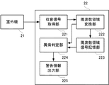
図9は、実施の形態3に係る室内機の機能構成例を示す図である。室内機22は、収音信号取得部221と、周波数領域変換部222と、周波数領域信号記憶部223と、異常判定部224と、警告情報出力部225とを備える。収音信号取得部221は、騒音測定装置5から収音信号を取得し、周波数領域変換部222に送る。周波数領域変換部222は、収音信号取得部221から受け取った収音信号を周波数領域信号に変換して周波数領域信号記憶部223に記憶し、異常判定部224に送る。異常判定部224は、周波数領域変換部222から受け取った周波数領域信号と周波数領域信号記憶部223が記憶している周波数領域信号との比較を行い、室外機21周辺の音に異常があるか否かを判定する。
FIG. 9 is a diagram illustrating a functional configuration example of the indoor unit according to
ヒートポンプ機器2は、HEMSからヒートポンプ機器状況を取得するヒートポンプ機器状況取得部を備えてもよい。この場合、異常判定部224は、周波数領域変換部222が変換した周波数領域信号と、周波数領域信号記憶部223が記憶する周波数領域信号とに加えて、ヒートポンプ機器状況取得部が取得したヒートポンプ機器状況を用いて、室外機21周辺の音の異常の有無を判定する。異常判定部224は、室外機21周辺の音に異常があると判定すると、室外機21周辺の音に異常があることを通知する警告情報を警告情報出力部225に送る。警告情報出力部225は、異常判定部224から受け取った警告情報を出力する。警告情報出力部225は、例えば、室内機22本体のLEDやリモコンの表示部などである。あるいは、警告情報出力部225は、サービスセンターサーバ4に接続して警告情報を送信してもよい。ここで、図10を用いてヒートポンプ機器2が行う処理について説明する。
The
図10は、実施の形態3に係るヒートポンプ機器の動作の一例を示すフローチャートである。以下の処理は、ヒートポンプ機器2が起動すると開始する。ヒートポンプ機器2の室内機22の収音信号取得部221は、騒音測定装置5から室外機21周辺の音を収音した収音信号を取得し(ステップS61)、周波数領域変換部222に送る。周波数領域変換部222は、収音信号取得部221から受け取った収音信号を周波数領域信号に変換し(ステップS62)、周波数領域信号記憶部223に記憶する(ステップS63)。また、周波数領域変換部222は、変換した周波数領域信号を異常判定部224に送る。異常判定部224は、周波数領域変換部222から受け取った周波数領域信号に基づいて、信号レベルが閾値以上の周波数帯域があるか否かを判定する(ステップS64)。
FIG. 10 is a flowchart illustrating an example of the operation of the heat pump device according to the third embodiment. The following process starts when the
閾値以上の周波数帯域がない場合(ステップS64;NO)、処理はステップS69に移行する。閾値以上の周波数帯域がある場合(ステップS64;YES)、異常判定部224は、信号レベルが決められた閾値以上の周波数帯域を特定する(ステップS65)。異常判定部224は、信号レベルが閾値以上の周波数帯域が予め決められた低周波帯に含まれるか否かを判定する(ステップS66)。低周波帯に含まれない場合(ステップS66;NO)、処理はステップS69に移行する。低周波帯に含まれる場合(ステップS66;YES)、異常判定部224は、信号レベルが閾値以上となっている状態が判定時間以上継続しているか否かを判定する(ステップS67)。判定時間以上継続していない場合(ステップS67;NO)、処理はステップS69に移行する。判定時間以上継続している場合(ステップS67;YES)、異常判定部224は、室外機21周辺の音に異常があると判定し、室外機21周辺の音に異常があることを通知する警告情報を警告情報出力部225に送る。警告情報出力部225は、異常判定部224から受け取った警告情報を出力する(ステップS68)。ヒートポンプ機器2の電源がOFFになっていなければ(ステップS69;NO)、処理はステップS61に戻り、ステップS61〜ステップS69を繰り返す。ヒートポンプ機器2の電源がOFFになると(ステップS69;YES)、処理を終了する。
If there is no frequency band equal to or greater than the threshold (step S64; NO), the process proceeds to step S69. When there is a frequency band equal to or higher than the threshold (step S64; YES), the
以上説明したように実施の形態3のヒートポンプ機器2によれば、ヒートポンプ機器2が備える室外機21周辺の音を収音し、収音した音の周波数ごとの信号レベルに基づいて、室外機21周辺の音に異常があると判定した場合に、室外機21周辺の音に異常があることを通知する警告情報を出力することで、室外機21の騒音で近隣住民とのトラブルに発展することを防止することができる。また、ユーザが室外機21周辺の音に異常があることに気づかず放置することによって室外機21が故障することを防止することができる。さらに、サービスセンターサーバ4に自動的に警告情報を送信することで、ユーザがサービスセンターサーバ4に連絡する手間を省くことができる。
As described above, according to the
上記の実施の形態1では、周波数領域信号をクラウドサーバ3内に蓄積し、クラウドサーバ3が室外機21周辺の音の異常の有無を判定する場合について説明した。実施の形態2では、周波数領域信号を制御装置1内に蓄積し、制御装置1が室外機21周辺の音の異常の有無を判定する場合について説明した。実施の形態3では、周波数領域信号をヒートポンプ機器2内に蓄積し、ヒートポンプ機器2が室外機21周辺の音の異常の有無を判定する場合について説明した。各機能のハードウェアの分担はこれに限らず、本発明の騒音管理システムは、建屋10に設置される室外機21および室内機22を含むヒートポンプ機器2の室外機21周辺の音を収音する騒音測定装置5が収音した収音信号を取得する収音信号取得部と、収音信号取得部が取得した収音信号を周波数領域信号に変換する周波数領域変換部と、周波数領域変換部が変換した周波数領域信号を記憶する周波数領域信号記憶部と、周波数領域信号取得部が取得した周波数領域信号と周波数領域信号記憶部が記憶している周波数領域信号との比較を行い、室外機21周辺の音に異常があるか否かを判定する異常判定部と、異常判定部が室外機21周辺の音に異常があると判定すると、室外機21周辺の音に異常があることを通知する警告情報を出力する警告情報出力部と、をいずれかの装置が備えていればよい。
In the first embodiment, the case where the frequency domain signal is accumulated in the
図11は、本発明の実施の形態に係る制御装置、クラウドサーバおよび室内機のハードウェア構成の一例を示す図である。制御装置1、クラウドサーバ3および室内機22は、それぞれの装置を制御するハードウェア構成としてプロセッサ101、メモリ102、インターフェース103を備える。これらの装置の各機能は、プロセッサ101がメモリ102に記憶されたプログラムを実行することにより実現される。インターフェース103は各装置を接続し、通信を確立させるためのものであり、必要に応じて複数の種類のインターフェースから構成されてもよい。図11では、プロセッサ101およびメモリ102をそれぞれ1つで構成する例を示しているが、複数のプロセッサ101および複数のメモリ102が連携して各機能を実行してもよい。
FIG. 11 is a diagram illustrating an example of a hardware configuration of the control device, the cloud server, and the indoor unit according to the embodiment of the present invention. The
その他、前記のハードウェア構成やフローチャートは一例であり、任意に変更および修正が可能である。 In addition, the hardware configuration and the flowchart described above are merely examples, and can be arbitrarily changed and modified.
プロセッサ101、メモリ102、インターフェース103から構成される各装置の処理を行う中心となる部分は、専用のシステムによらず、通常のコンピュータシステムを用いて実現可能である。例えば、前記の動作を実行するためのコンピュータプログラムを、コンピュータが読み取り可能な記録媒体(フレキシブルディスク、CD−ROM、DVD−ROMなど)に格納して配布し、当該コンピュータプログラムをコンピュータにインストールすることにより、前記の処理を実行する装置を構成してもよい。また、インターネットなどの通信ネットワーク上のサーバ装置が有する記憶装置に当該コンピュータプログラムを格納しておき、通常のコンピュータシステムがダウンロードなどすることで各装置を構成してもよい。
The central part that performs processing of each device including the
また、各装置の機能を、OS(オペレーティングシステム)とアプリケーションプログラムの分担、またはOSとアプリケーションプログラムとの協働により実現する場合などには、アプリケーションプログラム部分のみを記録媒体や記憶装置に格納してもよい。 In addition, when the functions of each device are realized by sharing an OS (operating system) and an application program or by cooperation between the OS and the application program, only the application program portion is stored in a recording medium or a storage device. Also good.
また、搬送波にコンピュータプログラムを重畳し、通信ネットワークを介して提供することも可能である。例えば、通信ネットワーク上の掲示板(BBS, Bulletin Board System)に前記コンピュータプログラムを掲示し、ネットワークを介して前記コンピュータプログラムを提供してもよい。そして、このコンピュータプログラムを起動し、OSの制御下で、他のアプリケーションプログラムと同様に実行することにより、前記の処理を実行できるように構成してもよい。 It is also possible to superimpose a computer program on a carrier wave and provide it via a communication network. For example, the computer program may be posted on a bulletin board (BBS, Bulletin Board System) on a communication network, and the computer program may be provided via the network. The computer program may be started and executed in the same manner as other application programs under the control of the OS, so that the above-described processing may be executed.
本発明は、本発明の広義の精神と範囲を逸脱することなく、様々な実施の形態および変形が可能とされるものである。また、前記した実施の形態は、本発明を説明するためのものであり、本発明の範囲を限定するものではない。本発明の範囲は、実施の形態ではなく、特許請求の範囲によって示される。そして、特許請求の範囲内およびそれと同等の発明の意義の範囲内で施される様々な変形が、本発明の範囲内とみなされる。 Various embodiments and modifications can be made to the present invention without departing from the broad spirit and scope of the present invention. The above-described embodiments are for explaining the present invention and do not limit the scope of the present invention. The scope of the present invention is shown not by the embodiments but by the claims. Various modifications within the scope of the claims and within the scope of the equivalent invention are considered to be within the scope of the present invention.
1 制御装置、2 ヒートポンプ機器、3 クラウドサーバ、4 サービスセンターサーバ、5 騒音測定装置、6 ネットワーク、10 建屋、11 収音信号取得部、12 周波数領域変換部、13 周波数領域信号送信部、14 警告情報受信部、15 警告情報出力部、16 周波数領域信号記憶部、17 異常判定部、21 室外機、22 室内機、31 周波数領域信号取得部、32 周波数領域信号記憶部、33 異常判定部、34 警告情報送信部、100,200 騒音管理システム、101 プロセッサ、102 メモリ、103 インターフェース、221 収音信号取得部、222 周波数領域変換部、223 周波数領域信号記憶部、224 異常判定部、225 警告情報出力部。
DESCRIPTION OF
Claims (12)
前記騒音測定装置が収音した収音信号を取得する収音信号取得部と、
前記収音信号を周波数ごとの信号レベルを表す周波数領域信号に変換する周波数領域変換部と、
前記周波数領域信号を前記サーバに送信する周波数領域信号送信部と、
前記サーバから、前記周波数領域信号に基づいて判定された前記室外機周辺の音の異常を通知する警告情報を受信する警告情報受信部と、
前記警告情報受信部が受信した前記警告情報を出力する警告情報出力部と、
を備える制御装置。 A noise measuring device that collects sound around the outdoor unit of the heat pump device including an outdoor unit and an indoor unit installed in a building, and a control device connected to a server connected to a network in the outdoor part of the building ,
A sound collection signal acquisition unit for acquiring a sound collection signal collected by the noise measuring device;
A frequency domain conversion unit that converts the collected sound signal into a frequency domain signal representing a signal level for each frequency;
A frequency domain signal transmitter for transmitting the frequency domain signal to the server;
A warning information receiving unit for receiving warning information for notifying abnormality of sound around the outdoor unit determined based on the frequency domain signal from the server;
A warning information output unit that outputs the warning information received by the warning information receiving unit;
A control device comprising:
前記制御装置から、前記周波数領域信号を取得する周波数領域信号取得部と、
前記周波数領域信号から、前記室外機周辺の音に異常があるか否かを判定する異常判定部と、
前記異常判定部が前記室外機周辺の音に異常があると判定すると、前記室外機周辺の音に異常があることを通知する警告情報を、前記制御装置および前記ヒートポンプ機器の点検修理サービスを提供するサービスセンターが管理するサービスセンターサーバの少なくともいずれかに送信する警告情報送信部と、
を備えるサーバ。 A server connected to the control device according to claim 1,
A frequency domain signal acquisition unit for acquiring the frequency domain signal from the control device;
From the frequency domain signal, an abnormality determination unit that determines whether there is an abnormality in the sound around the outdoor unit,
When the abnormality determination unit determines that there is an abnormality in the sound around the outdoor unit, it provides warning information for notifying that there is an abnormality in the sound around the outdoor unit, and provides inspection and repair services for the control device and the heat pump device. A warning information transmitter that transmits to at least one of the service center servers managed by the service center;
A server comprising
前記周波数領域信号記憶部に前記周波数領域信号が記憶された後は、前記閾値は、前記周波数領域信号記憶部に記憶された前記周波数領域信号の信号レベルから算出される請求項3に記載のサーバ。 A frequency domain signal storage unit for storing the frequency domain signal acquired by the frequency domain signal acquisition unit;
The server according to claim 3, wherein after the frequency domain signal is stored in the frequency domain signal storage unit, the threshold value is calculated from a signal level of the frequency domain signal stored in the frequency domain signal storage unit. .
前記周波数領域信号記憶部に前記周波数領域信号が記憶された後は、前記低周波帯は、前記周波数領域信号記憶部に記憶された前記周波数領域信号のうち、過去に異常と判定された前記周波数領域信号の周波数帯域から算出される請求項3から5のいずれか1項に記載のサーバ。 A frequency domain signal storage unit for storing the frequency domain signal acquired by the frequency domain signal acquisition unit;
After the frequency domain signal is stored in the frequency domain signal storage unit, the low frequency band is the frequency that has been determined to be abnormal in the past among the frequency domain signals stored in the frequency domain signal storage unit. The server according to claim 3, wherein the server is calculated from a frequency band of the region signal.
前記異常判定部は、前記周波数領域信号に加えて、前記ヒートポンプ機器状況取得部が取得した前記ヒートポンプ機器状況を用いて、前記室外機周辺の音に異常があるか否かを判定する、
請求項2から6のいずれか1項に記載のサーバ。 A heat pump device status acquisition unit that acquires a heat pump device status indicating at least one of an operating status of the heat pump device, a noise status around the building, and an implementation status of inspection and repair of the heat pump device from the control device; ,
The abnormality determination unit determines whether or not there is an abnormality in the sound around the outdoor unit using the heat pump device status acquired by the heat pump device status acquisition unit in addition to the frequency domain signal.
The server according to any one of claims 2 to 6.
前記室外機周辺の音を収音する騒音測定装置と、
請求項1に記載の制御装置と、
請求項2から7のいずれか1項に記載のサーバと、
を備える騒音監視システム。 Heat pump equipment including outdoor units and indoor units installed in the building;
A noise measuring device for collecting sounds around the outdoor unit;
A control device according to claim 1;
A server according to any one of claims 2 to 7;
A noise monitoring system comprising:
前記騒音測定装置が収音した収音信号を取得する収音信号取得部と、
前記収音信号を周波数ごとの信号レベルを表す周波数領域信号に変換する周波数領域変換部と、
前記周波数領域信号から、前記室外機周辺の音に異常があるか否かを判定する異常判定部と、
前記異常判定部が前記室外機周辺の音に異常があると判定すると、前記室外機周辺の音に異常があることを通知する警告情報を出力する警告情報出力部と、
を備える制御装置。 A control device connected to a noise measuring device that collects sound around the outdoor unit of the heat pump device including the outdoor unit and the indoor unit installed in the building,
A sound collection signal acquisition unit for acquiring a sound collection signal collected by the noise measuring device;
A frequency domain conversion unit that converts the collected sound signal into a frequency domain signal representing a signal level for each frequency;
From the frequency domain signal, an abnormality determination unit that determines whether there is an abnormality in the sound around the outdoor unit,
When the abnormality determining unit determines that there is an abnormality in the sound around the outdoor unit, a warning information output unit that outputs warning information notifying that there is an abnormality in the sound around the outdoor unit;
A control device comprising:
室外機と、
前記室外機周辺の音を収音する騒音測定装置と、
前記騒音測定装置が収音した収音信号を取得する収音信号取得部、
前記収音信号を周波数ごとの信号レベルを表す周波数領域信号に変換する周波数領域変換部、
前記周波数領域信号から、前記室外機周辺の音に異常があるか否かを判定する異常判定部、および、
前記異常判定部が前記室外機周辺の音に異常があると判定すると、前記室外機周辺の音に異常があることを通知する警告情報を出力する警告情報出力部、
を含む室内機と、
を備えるヒートポンプ機器。 Installed in the building,
Outdoor unit,
A noise measuring device for collecting sounds around the outdoor unit;
A sound collection signal acquisition unit for acquiring a sound collection signal collected by the noise measurement device;
A frequency domain converter that converts the collected sound signal into a frequency domain signal representing a signal level for each frequency;
An abnormality determining unit that determines whether there is an abnormality in the sound around the outdoor unit from the frequency domain signal, and
When the abnormality determining unit determines that there is an abnormality in the sound around the outdoor unit, a warning information output unit that outputs warning information notifying that there is an abnormality in the sound around the outdoor unit;
An indoor unit including
Heat pump equipment comprising.
前記収音信号を周波数ごとの信号レベルを表す周波数領域信号に変換する周波数領域変換部と、
前記周波数領域信号から、前記室外機周辺の音に異常があるか否かを判定する異常判定部と、
前記異常判定部が前記室外機周辺の音に異常があると判定すると、前記室外機周辺の音に異常があることを通知する警告情報を出力する警告情報出力部と、
を備える騒音監視システム。 A sound collection signal acquisition unit that acquires a sound collection signal collected by a noise measurement device that collects sound around the outdoor unit of a heat pump device including an outdoor unit and an indoor unit installed in a building;
A frequency domain conversion unit that converts the collected sound signal into a frequency domain signal representing a signal level for each frequency;
From the frequency domain signal, an abnormality determination unit that determines whether there is an abnormality in the sound around the outdoor unit,
When the abnormality determining unit determines that there is an abnormality in the sound around the outdoor unit, a warning information output unit that outputs warning information notifying that there is an abnormality in the sound around the outdoor unit;
A noise monitoring system comprising:
建屋に設置される室外機および室内機を含むヒートポンプ機器の前記室外機周辺の音を収音する騒音測定装置が収音した収音信号を周波数ごとの信号レベルを表す周波数領域信号に変換する周波数領域変換部、
前記周波数領域信号から、前記室外機周辺の音に異常があるか否かを判定する異常判定部、ならびに、
前記異常判定部が前記室外機周辺の音に異常があると判定すると、前記室外機周辺の音に異常があることを通知する警告情報を出力する警告情報出力部、
として機能させるプログラム。 Computer
The frequency at which the collected sound signal collected by the noise measuring device for collecting the sound around the outdoor unit of the heat pump device including the outdoor unit and the indoor unit installed in the building is converted into a frequency domain signal representing a signal level for each frequency. Area converter,
From the frequency domain signal, an abnormality determination unit that determines whether there is an abnormality in the sound around the outdoor unit, and
When the abnormality determining unit determines that there is an abnormality in the sound around the outdoor unit, a warning information output unit that outputs warning information notifying that there is an abnormality in the sound around the outdoor unit;
Program to function as.
Priority Applications (1)
| Application Number | Priority Date | Filing Date | Title |
|---|---|---|---|
| JP2016078794A JP6749131B2 (en) | 2016-04-11 | 2016-04-11 | Control device, server, noise monitoring system, heat pump device and program |
Applications Claiming Priority (1)
| Application Number | Priority Date | Filing Date | Title |
|---|---|---|---|
| JP2016078794A JP6749131B2 (en) | 2016-04-11 | 2016-04-11 | Control device, server, noise monitoring system, heat pump device and program |
Publications (2)
| Publication Number | Publication Date |
|---|---|
| JP2017190880A true JP2017190880A (en) | 2017-10-19 |
| JP6749131B2 JP6749131B2 (en) | 2020-09-02 |
Family
ID=60085839
Family Applications (1)
| Application Number | Title | Priority Date | Filing Date |
|---|---|---|---|
| JP2016078794A Expired - Fee Related JP6749131B2 (en) | 2016-04-11 | 2016-04-11 | Control device, server, noise monitoring system, heat pump device and program |
Country Status (1)
| Country | Link |
|---|---|
| JP (1) | JP6749131B2 (en) |
Cited By (7)
| Publication number | Priority date | Publication date | Assignee | Title |
|---|---|---|---|---|
| CN108469109A (en) * | 2018-03-01 | 2018-08-31 | 广东美的制冷设备有限公司 | Detection method, device, system, air conditioner and the storage medium of unit exception |
| CN109458720A (en) * | 2018-10-22 | 2019-03-12 | 四川虹美智能科技有限公司 | A kind of central air conditioner system |
| CN110425710A (en) * | 2019-08-30 | 2019-11-08 | 盈盛智创科技(广州)有限公司 | A kind of fault detection method of air-conditioning, device, equipment and storage medium |
| JP2019199994A (en) * | 2018-05-16 | 2019-11-21 | 日立ジョンソンコントロールズ空調株式会社 | Air conditioner |
| JP2020046160A (en) * | 2018-09-21 | 2020-03-26 | 東芝キヤリア株式会社 | Air conditioning device and method for controlling air conditioning device |
| JPWO2021245941A1 (en) * | 2020-06-05 | 2021-12-09 | ||
| CN119594524A (en) * | 2023-09-08 | 2025-03-11 | 青岛海尔空调器有限总公司 | Intelligent noise reduction control method, device, equipment and computer storage medium |
Citations (8)
| Publication number | Priority date | Publication date | Assignee | Title |
|---|---|---|---|---|
| JPH03269221A (en) * | 1990-03-19 | 1991-11-29 | Hitachi Ltd | Abnormal sound diagnosis device for rotating equipment |
| JPH0599475A (en) * | 1991-10-08 | 1993-04-20 | Daikin Ind Ltd | Noise diagnosis device for air conditioner |
| JPH11118592A (en) * | 1997-10-15 | 1999-04-30 | Hitachi Ltd | Device abnormality diagnosis device and plant device equipped with the same |
| JP2002041143A (en) * | 2000-07-31 | 2002-02-08 | Chiyoda Corp | Method for diagnosing abnormalities in operation section and method for diagnosing valve abnormalities in compressor |
| JP2004132683A (en) * | 2002-08-09 | 2004-04-30 | Daikin Ind Ltd | Failure diagnosis system, examination device, and data server |
| JP2010065594A (en) * | 2008-09-10 | 2010-03-25 | Mitsubishi Electric Corp | Failure diagnostic system of electric blower and electric equipment mounted with the same |
| JP2010198362A (en) * | 2009-02-25 | 2010-09-09 | Mitsubishi Heavy Ind Ltd | Remote maintenance management system for air conditioning equipment and remote maintenance management server |
| US20140137583A1 (en) * | 2012-11-12 | 2014-05-22 | Seontaek Kim | Apparatus for controlling an air conditioner |
-
2016
- 2016-04-11 JP JP2016078794A patent/JP6749131B2/en not_active Expired - Fee Related
Patent Citations (8)
| Publication number | Priority date | Publication date | Assignee | Title |
|---|---|---|---|---|
| JPH03269221A (en) * | 1990-03-19 | 1991-11-29 | Hitachi Ltd | Abnormal sound diagnosis device for rotating equipment |
| JPH0599475A (en) * | 1991-10-08 | 1993-04-20 | Daikin Ind Ltd | Noise diagnosis device for air conditioner |
| JPH11118592A (en) * | 1997-10-15 | 1999-04-30 | Hitachi Ltd | Device abnormality diagnosis device and plant device equipped with the same |
| JP2002041143A (en) * | 2000-07-31 | 2002-02-08 | Chiyoda Corp | Method for diagnosing abnormalities in operation section and method for diagnosing valve abnormalities in compressor |
| JP2004132683A (en) * | 2002-08-09 | 2004-04-30 | Daikin Ind Ltd | Failure diagnosis system, examination device, and data server |
| JP2010065594A (en) * | 2008-09-10 | 2010-03-25 | Mitsubishi Electric Corp | Failure diagnostic system of electric blower and electric equipment mounted with the same |
| JP2010198362A (en) * | 2009-02-25 | 2010-09-09 | Mitsubishi Heavy Ind Ltd | Remote maintenance management system for air conditioning equipment and remote maintenance management server |
| US20140137583A1 (en) * | 2012-11-12 | 2014-05-22 | Seontaek Kim | Apparatus for controlling an air conditioner |
Cited By (9)
| Publication number | Priority date | Publication date | Assignee | Title |
|---|---|---|---|---|
| CN108469109A (en) * | 2018-03-01 | 2018-08-31 | 广东美的制冷设备有限公司 | Detection method, device, system, air conditioner and the storage medium of unit exception |
| JP2019199994A (en) * | 2018-05-16 | 2019-11-21 | 日立ジョンソンコントロールズ空調株式会社 | Air conditioner |
| JP2020046160A (en) * | 2018-09-21 | 2020-03-26 | 東芝キヤリア株式会社 | Air conditioning device and method for controlling air conditioning device |
| JP7300252B2 (en) | 2018-09-21 | 2023-06-29 | 東芝キヤリア株式会社 | AIR CONDITIONER AND CONTROL METHOD OF AIR CONDITIONER |
| CN109458720A (en) * | 2018-10-22 | 2019-03-12 | 四川虹美智能科技有限公司 | A kind of central air conditioner system |
| CN110425710A (en) * | 2019-08-30 | 2019-11-08 | 盈盛智创科技(广州)有限公司 | A kind of fault detection method of air-conditioning, device, equipment and storage medium |
| JPWO2021245941A1 (en) * | 2020-06-05 | 2021-12-09 | ||
| JP7325630B2 (en) | 2020-06-05 | 2023-08-14 | 三菱電機株式会社 | Air conditioner diagnostic system and learning device |
| CN119594524A (en) * | 2023-09-08 | 2025-03-11 | 青岛海尔空调器有限总公司 | Intelligent noise reduction control method, device, equipment and computer storage medium |
Also Published As
| Publication number | Publication date |
|---|---|
| JP6749131B2 (en) | 2020-09-02 |
Similar Documents
| Publication | Publication Date | Title |
|---|---|---|
| JP6749131B2 (en) | Control device, server, noise monitoring system, heat pump device and program | |
| US10397042B2 (en) | Method and apparatus for automation and alarm architecture | |
| US10803720B2 (en) | Intelligent smoke sensor with audio-video verification | |
| JP6493828B2 (en) | Outing support device and program | |
| WO2016049778A1 (en) | Method and apparatus for resource balancing in an automation and alarm architecture | |
| JP2011055121A (en) | Equipment control system | |
| US20230244437A1 (en) | Systems and methods to adjust loudness of connected and media source devices based on context | |
| JP2009212699A (en) | Information processing system and information processor | |
| JP7285497B2 (en) | EQUIPMENT MANAGEMENT SYSTEM, CONTROL METHOD, AND PROGRAM | |
| JP6022797B2 (en) | Alarm linkage system | |
| US8761361B2 (en) | Management unit with microphone | |
| JP5964559B2 (en) | Alarm linkage system | |
| JP2020136771A (en) | Information notification device and disaster-time situation notification system | |
| KR101965284B1 (en) | System and method for controlling domestic appliances, and computer readable medium for performing the method | |
| JP6594110B2 (en) | Control device, control system, and program | |
| US20220036876A1 (en) | Speech apparatus, server, and control system | |
| CN115309062B (en) | Device control method, device, storage medium and electronic device | |
| JP2011151680A (en) | Intercom system | |
| JP2020167567A (en) | Control system and control method | |
| KR102282710B1 (en) | Farm House's Power Distribution Method with Patient Monitering Means and System thereof | |
| JP2015175793A (en) | Noise measurement system, noise measurement program, and noise measurement method | |
| CN117542355A (en) | Distributed voice awakening method and device, storage medium and electronic device | |
| CN115312050B (en) | Instruction response method, storage medium and electronic device | |
| TWI578279B (en) | Intellectual alarm module and intellectual alarm method | |
| CN115312049B (en) | Instruction response method, storage medium and electronic device |
Legal Events
| Date | Code | Title | Description |
|---|---|---|---|
| A621 | Written request for application examination |
Free format text: JAPANESE INTERMEDIATE CODE: A621 Effective date: 20190314 |
|
| A977 | Report on retrieval |
Free format text: JAPANESE INTERMEDIATE CODE: A971007 Effective date: 20191213 |
|
| A131 | Notification of reasons for refusal |
Free format text: JAPANESE INTERMEDIATE CODE: A131 Effective date: 20200107 |
|
| A521 | Request for written amendment filed |
Free format text: JAPANESE INTERMEDIATE CODE: A523 Effective date: 20200306 |
|
| TRDD | Decision of grant or rejection written | ||
| A01 | Written decision to grant a patent or to grant a registration (utility model) |
Free format text: JAPANESE INTERMEDIATE CODE: A01 Effective date: 20200714 |
|
| A61 | First payment of annual fees (during grant procedure) |
Free format text: JAPANESE INTERMEDIATE CODE: A61 Effective date: 20200811 |
|
| R150 | Certificate of patent or registration of utility model |
Ref document number: 6749131 Country of ref document: JP Free format text: JAPANESE INTERMEDIATE CODE: R150 |
|
| R250 | Receipt of annual fees |
Free format text: JAPANESE INTERMEDIATE CODE: R250 |
|
| LAPS | Cancellation because of no payment of annual fees |