JP2019199683A - Storage tank - Google Patents
Storage tank Download PDFInfo
- Publication number
- JP2019199683A JP2019199683A JP2018092734A JP2018092734A JP2019199683A JP 2019199683 A JP2019199683 A JP 2019199683A JP 2018092734 A JP2018092734 A JP 2018092734A JP 2018092734 A JP2018092734 A JP 2018092734A JP 2019199683 A JP2019199683 A JP 2019199683A
- Authority
- JP
- Japan
- Prior art keywords
- storage tank
- liquid
- peripheral wall
- outlet
- partition wall
- Prior art date
- Legal status (The legal status is an assumption and is not a legal conclusion. Google has not performed a legal analysis and makes no representation as to the accuracy of the status listed.)
- Granted
Links
Images


Classifications
-
- E—FIXED CONSTRUCTIONS
- E03—WATER SUPPLY; SEWERAGE
- E03C—DOMESTIC PLUMBING INSTALLATIONS FOR FRESH WATER OR WASTE WATER; SINKS
- E03C1/00—Domestic plumbing installations for fresh water or waste water; Sinks
- E03C1/12—Plumbing installations for waste water; Basins or fountains connected thereto; Sinks
- E03C1/122—Pipe-line systems for waste water in building
- E03C1/1222—Arrangements of devices in domestic waste water pipe-line systems
Landscapes
- Engineering & Computer Science (AREA)
- Structural Engineering (AREA)
- Environmental & Geological Engineering (AREA)
- Health & Medical Sciences (AREA)
- Life Sciences & Earth Sciences (AREA)
- Hydrology & Water Resources (AREA)
- Public Health (AREA)
- Water Supply & Treatment (AREA)
- Sink And Installation For Waste Water (AREA)
- Devices For Dispensing Beverages (AREA)
- Details Of Rigid Or Semi-Rigid Containers (AREA)
Abstract
Description
本発明は、貯留槽に関する。 The present invention relates to a storage tank.
集合住宅等の排水システムとしては、サイホンの原理を利用したサイホン排水システムと呼ばれるものがある。サイホン排水システムによれば、水廻り機器からの排水を行う際、サイホン排水管に生じたサイホン力により、当該排水を促進させることができる。その一方、サイホン排水システムでは、多量の液体の排水を一度に行うことを想定し、サイホン排水管よりも上流に、排水の促進(サイホン力の発生)が開始されるまでの間、一時的に液体を蓄えることができる貯留槽を設ける必要がある。こうした貯留槽としては、当該貯留槽の流出口と貯留槽本体との間に流路縮小部を設けると共に、当該流路縮小部の一部に、外側に膨出する内壁面を設けたものがある(例えば、特許文献1参照。)。 As a drainage system for an apartment house, there is a so-called siphon drainage system using the principle of siphon. According to the siphon drainage system, when draining from a watering device, the drainage can be promoted by the siphon force generated in the siphon drain pipe. On the other hand, in the siphon drainage system, it is assumed that a large amount of liquid is drained at once, and until the drainage promotion (generation of siphon force) starts upstream from the siphon drainage pipe, It is necessary to provide a storage tank that can store liquid. As such a storage tank, a flow path reducing portion is provided between the outlet of the storage tank and the storage tank body, and an inner wall surface bulging outward is provided in a part of the flow path reduced portion. (For example, refer to Patent Document 1).
上述した貯留槽によれば、流出口付近に滞留した液体が前記流路縮小部の内壁面に沿って前記流出口から離間される方向に導かれる。これにより、上述した貯留槽によれば、液体の流れが流出口付近で阻害されることなく、多くの液体を迅速かつスムーズに流出させることができる。 According to the storage tank described above, the liquid staying in the vicinity of the outlet is guided in a direction away from the outlet along the inner wall surface of the flow path reducing portion. Thereby, according to the storage tank mentioned above, many liquids can be flowed out quickly and smoothly, without the flow of a liquid being obstruct | occluded in the outflow port vicinity.
しかしながら、例えば、上述した貯留槽を用いた場合等であっても、多くの液体をより迅速かつスムーズに流出させる余地があった。 However, for example, even when the above-described storage tank is used, there is room for more liquid to flow out more quickly and smoothly.
本発明の目的は、多くの液体を迅速かつスムーズに流出させることができる、新規な貯留槽を提供することである。 An object of the present invention is to provide a novel storage tank capable of allowing many liquids to flow out quickly and smoothly.
本発明に係る貯留槽は、流出口付近の液体の水頭を迅速に高めた場合、多くの液体を迅速かつスムーズに流出させることができることに着目してなされたものである。 The storage tank according to the present invention is made by paying attention to the fact that a large amount of liquid can flow out quickly and smoothly when the liquid head in the vicinity of the outlet is quickly raised.
本発明に係る貯留槽は、液体が流入する流入口と、前記液体が流出する流出口と、を有し、前記流入口から流入した前記液体を内部に貯留可能な貯留槽であって、底面に対して起立する周壁と、前記底面に対して起立する仕切壁と、を備えており、前記周壁は、前記流入口が形成されている流入口部分と、前記流入口部分と対向していると共に前記流出口が形成されている流出口部分と、を備えており、前記仕切壁は、前記流出口に向かって延在している。
本発明に係る貯留槽によれば、流出口付近の液体の水頭を迅速に高めることができる。このため、本発明に係る貯留槽によれば、多くの液体を迅速かつスムーズに流出させることができる。
A storage tank according to the present invention is a storage tank having an inlet through which a liquid flows in and an outlet through which the liquid flows out, and capable of storing the liquid flowing in from the inlet. A peripheral wall that stands up against the bottom surface, and a partition wall that stands up against the bottom surface, the peripheral wall facing the inlet portion where the inlet is formed, and the inlet portion And an outlet portion where the outlet is formed, and the partition wall extends toward the outlet.
According to the storage tank according to the present invention, the liquid head near the outlet can be quickly increased. For this reason, according to the storage tank which concerns on this invention, many liquids can be poured out quickly and smoothly.
本発明に係る貯留槽において、前記仕切壁は、当該仕切壁から前記液体が越流可能な高さを有していることが好ましい。
この場合、流出口付近の液体の水頭が一定以上となると、当該流出口付近の液体を仕切壁から逃がすことができる。このため、液体の流れが流出口付近で阻害され難く、より迅速かつスムーズな排水が可能になる。
In the storage tank according to the present invention, it is preferable that the partition wall has a height that allows the liquid to overflow from the partition wall.
In this case, when the liquid head in the vicinity of the outlet becomes a certain level or more, the liquid in the vicinity of the outlet can be released from the partition wall. For this reason, it is difficult for the flow of the liquid to be disturbed in the vicinity of the outlet, and more rapid and smooth drainage is possible.
本発明に係る貯留槽において、前記仕切壁の高さは、前記流出口に向かうに従って高くなることが好ましい。
この場合、流出口付近の液体の水頭を高めつつ、当該流出口から離れるに従って、仕切壁から逃がす液体の量を増加させることができる。
The storage tank which concerns on this invention WHEREIN: It is preferable that the height of the said partition wall becomes high as it goes to the said outflow port.
In this case, it is possible to increase the amount of liquid that escapes from the partition wall as the distance from the outlet increases while increasing the liquid head near the outlet.
本発明に係る貯留槽において、前記流出口は、前記流入口よりも低い位置に設けられていることが好ましい。
この場合、より迅速かつスムーズな排水が可能になる。
The storage tank which concerns on this invention WHEREIN: It is preferable that the said outflow port is provided in the position lower than the said inflow port.
In this case, more rapid and smooth drainage is possible.
本発明に係る貯留槽において、前記仕切壁は、前記周壁の前記流出口部分の一部として構成されており、前記周壁の前記流出口部分と隣接する当該周壁の流出側隣接部分の内面は、前記仕切壁の頂面に繋がっていると共に、当該仕切壁の頂面と同一面を形作っていることが好ましい。ここで、「同一面」とは、「滑らかに繋がる連続的な面」をいい、「平面」及び「曲面」のいずれの面も含まれる。
この場合、仕切壁から逃がした液体を、周壁の流出側隣接部分の内面に沿って更に逃がすことができる。
In the storage tank according to the present invention, the partition wall is configured as a part of the outlet portion of the peripheral wall, and an inner surface of the outlet side adjacent portion of the peripheral wall adjacent to the outlet portion of the peripheral wall is It is preferable that it is connected to the top surface of the partition wall and forms the same surface as the top surface of the partition wall. Here, the “same surface” means “a continuous surface smoothly connected”, and includes both a “plane” and a “curved surface”.
In this case, the liquid escaped from the partition wall can be further escaped along the inner surface of the peripheral portion on the outflow side.
本発明に係る貯留槽において、前記仕切壁の頂面の端縁部は、前記貯留槽の内部に向かって凸の曲面であることが好ましい。
この場合、流出口付近の液体を、仕切壁から周壁の流出側隣接部分の内面に沿って効率的かつスムーズに逃がすことができる。
The storage tank which concerns on this invention WHEREIN: It is preferable that the edge part of the top surface of the said partition wall is a convex curved surface toward the inside of the said storage tank.
In this case, the liquid in the vicinity of the outlet can be efficiently and smoothly released from the partition wall along the inner surface of the peripheral wall adjacent to the outflow side.
本発明に係る貯留槽において、前記周壁の前記流入口部分は、前記周壁の前記流入口部分と隣接する当該周壁の流入側隣接部分よりも流出側に窪んでいることが好ましい。
この場合、貯留槽内を流れる液体は、液体の流出方向に戻り易くなる。このため、より迅速かつスムーズに排水することができる。
The storage tank which concerns on this invention WHEREIN: It is preferable that the said inflow port part of the said surrounding wall is depressed in the outflow side rather than the inflow side adjacent part of the said surrounding wall adjacent to the said inflow port part of the said surrounding wall.
In this case, the liquid flowing in the storage tank easily returns to the liquid outflow direction. For this reason, it can drain more quickly and smoothly.
本発明に係る貯留槽において、前記仕切壁は、溝部と隣接している位置から起立していることが好ましい。
この場合、少量の液体であっても当該液体を溝部により迅速に集めることができる。このため、更に迅速かつスムーズな排水が可能になる。特に、この場合、仕切壁は、溝部と隣接している位置から起立しているため、流出口付近の液体の水頭をより迅速に高めることができる。
In the storage tank according to the present invention, it is preferable that the partition wall is erected from a position adjacent to the groove.
In this case, even a small amount of liquid can be quickly collected by the groove. For this reason, more rapid and smooth drainage becomes possible. In particular, in this case, since the partition wall is erected from a position adjacent to the groove, the liquid head near the outlet can be raised more quickly.
前記周壁の前記流出口部分は、前記周壁の前記流出口部分と隣接する当該周壁の流出側隣接部分よりも流出側に突出していることが好ましい。
この場合、流出口付近に液体を集め易い構造となる。このため、本発明に係る貯留槽によれば、多くの液体を迅速かつスムーズに流出させることができる。
The outlet portion of the peripheral wall preferably protrudes to the outflow side from the outflow side adjacent portion of the peripheral wall adjacent to the outflow portion of the peripheral wall.
In this case, the liquid is easily collected in the vicinity of the outlet. For this reason, according to the storage tank which concerns on this invention, many liquids can be poured out quickly and smoothly.
本発明に係る貯留槽において、前記周壁の前記流出側隣接部分の内面は、側面視の断面形状が流出側に向かって凸の曲線からなる曲面であることが好ましい。
この場合、仕切壁から逃がした液体を、上下方向(縦方向)の対流(循環)を生じさせながら、周壁の流出側隣接部分の内面に沿って更に逃がすことができる。
The storage tank which concerns on this invention WHEREIN: It is preferable that the inner surface of the said outflow side adjacent part of the said surrounding wall is a curved surface which the cross-sectional shape of a side view becomes a convex curve toward an outflow side.
In this case, the liquid that has escaped from the partition wall can be further escaped along the inner surface of the adjacent portion on the outflow side of the peripheral wall while causing convection (circulation) in the vertical direction (vertical direction).
本発明に係る貯留槽において、前記流入口と前記流出口との間を延在している液体通過領域と、前記液体通過領域を挟んだ両側のそれぞれの位置に配置されている液体滞留領域と、を備えることが好ましい。
この場合、液体通過領域に液体を流しつつ、当該液体の残りを液体滞留領域内に滞留させることができる。このため、液体の流れが流出口付近で阻害され難く、より迅速かつスムーズな排水を一定量だけ連続して行うことが可能になる。
In the storage tank according to the present invention, a liquid passage region extending between the inflow port and the outflow port, and a liquid retention region disposed at each position on both sides of the liquid passage region Are preferably provided.
In this case, the remaining liquid can be retained in the liquid retention region while flowing the liquid in the liquid passage region. For this reason, it is difficult for the liquid flow to be obstructed in the vicinity of the outflow port, and it becomes possible to continuously perform more rapid and smooth drainage by a certain amount.
本発明に係る貯留槽において、前記周壁の内面のうち、平面視で前記貯留槽の内部に隅部を形作る当該周壁の内面は、平面視の輪郭形状が曲線からなる曲面であることが好ましい。
この場合、液体通過領域から流れた液体を、液体通過領域と液体滞留領域との間でより効率的に対流させることができる。
The storage tank which concerns on this invention WHEREIN: It is preferable that the inner surface of the said surrounding wall which forms a corner part inside the said storage tank by planar view among the inner surfaces of the said circumferential wall is a curved surface from which planar outline shape becomes a curve.
In this case, the liquid flowing from the liquid passage region can be convected more efficiently between the liquid passage region and the liquid retention region.
本発明によれば、多くの液体を迅速かつスムーズに流出させることができる、新規な貯留槽を提供することができる。 ADVANTAGE OF THE INVENTION According to this invention, the novel storage tank which can flow out many liquids rapidly and smoothly can be provided.
以下、図面を参照して、本発明の様々な実施形態に係る貯留槽について詳細に説明をする。 Hereinafter, storage tanks according to various embodiments of the present invention will be described in detail with reference to the drawings.
[本発明に係る貯留槽を適用可能な排水システム]
図19は、本発明に係る貯留槽を適用可能な排水システムの一例を一部断面で示す模式的なシステム図である。図19中、符号100は、本発明の一実施形態に係る貯留槽を適用可能な、排水システムの一例である。本例では、排水システム100は、サイホン排水システムである。サイホン排水システムは、サイホンの原理を利用した排水システムである。サイホン排水システムによれば、水廻り機器からの排水を行う際、サイホン排水管に生じたサイホン力により、当該排水を促進させることができる。サイホン排水システムは、例えば、1棟の建物が複数階に区画された集合住宅の排水システムとして採用される。
[Drainage system to which storage tank according to the present invention is applicable]
FIG. 19 is a schematic system diagram showing in partial cross section an example of a drainage system to which the storage tank according to the present invention can be applied. In FIG. 19, the code |
本例では、排水システム100は、水廻り器具110と、器具排水管120と、本発明の一実施形態に係る貯留槽1と、サイホン排水管130と、を備えている。
In this example, the
水廻り器具110は、建物の各階に配置されている。水廻り器具110としては、例えば、浴槽(例えば、ユニットバス)、洗面台、流し台が挙げられる。本例では、水廻り器具110は、浴槽である。
The watering
器具排水管120は、水廻り器具110と貯留槽1とを接続している。本例では、器具排水管120は、床下空間S内に配置されている。本例では、床下空間Sは、建築物の床部材101と床スラブ102との間に形成された空間である。また本例では、器具排水管120は、縦方向に延びている上流側部分120aと、横方向に延びている下流側部分120bとで構成されている。上流側部分120aは、水廻り器具110に接続されている。下流側部分120bは、上流側部分120aに繋がっている。本例では、下流側部分120bは、上流側部分120aから下流に向かうに従って下方に傾斜している。下流側部分120bは、貯留槽1に接続されている。なお、本例では、下流側部分120bの途中に排水トラップ121を介在させている。
The
サイホン排水管130は、貯留槽1と立て管150とを接続している。立て管150は、建物の各階を上下方向に貫く排水管である。本例では、サイホン排水管130は、床下空間S内に配置された横引き管130aと、床スラブ102を貫通して下方に垂下している竪管130bとで構成されている。横引き管130aは、貯留槽1に接続されている。本例では、横引き管130aは、ほぼ水平の無勾配となるように横方向に延びている。詳細には、水廻り器具110が設置されている階の床スラブ102に沿って、略水平の無勾配で配管されている。竪管130bは、横引き管130aに繋がっている。竪管130bは、管継手140を介して立て管150に接続されている。詳細には、竪管130bは、横引き管130aの略垂直下方に延在して、垂下部を形成しサイホン力(例えば、負圧力)を発生させる。
The siphon
本例の排水システム100では、まず水廻り器具110の流出口とサイホン排水管130の横引き管130aとの高低差H1から、水廻り器具110から液体を流出させる。水廻り器具110から流出した液体(例えば、水)は、当該液体の自重(落下押し込み圧力)によって、器具排水管120から貯留槽1に流入する。貯留槽1は、液体の一部を内部に蓄えながら、残りの液体をサイホン排水管130に流出させる。
In the
本例において、サイホン排水管130は、サイホン力による吸引力を発生させるサイホン排水路を形成する。サイホン排水路では、サイホン排水管130内に発生したサイホン力によって、サイホン排水管130からの液体の排水を促進させることができる。
In this example, the siphon
本例のサイホン排水路においては、水廻り器具110の流出口とサイホン排水管130の横引き管130aの高低差H1による、水廻り器具110からの排水の落下押し込み圧力で、器具排水管120及びサイホン排水管130の横引き管130aを充水させ、サイホン排水管130の横引き管130aの充水により、当該サイホン排水管130の竪管130b(垂下長H2)に達した排水が当該竪管130bを落下し始め、サイホン排水管130の横引き管130aが満水状態になることで、サイホン作用が発生する。このサイホン作用を排水動力として、サイホン排水路内に発生する高速の流れにより、水廻り器具110からの排水が行われ、排水は、管継手140の内部へとスムーズかつ速やかに放出される。
In the siphon drainage channel of the present example, the
本例では、排水システム100として、サイホン排水システムを採用したことから、排水管内部が満水状態に充填される満流排水となる。このように排水システム100として、サイホン排水システムを採用すれば、液体の排水が満流排水となるため、管内に固形物が付着するのを防止できると共に、小口径管を使用することができる。また、本例では、排水システム100として、サイホン排水システムを採用したことから、排水管を無勾配で配置することができる。このように排水システム100として、サイホン排水システムを採用すれば、排水管を無勾配で配置することができることにより、排水管を配置する床下の空間高さを低くすることが可能になる。また本例では、排水システム100として、サイホン排水システムを採用したことから、排水元(例えば、各種水廻り器具110)から立て管150までの延長距離(例えば、水廻り器具110の流出口からサイホン排水管130の竪管130bまでの水平長L)を長くすることができ(図17参照)、ひいては、居室レイアウトの自由度を上げることが可能となる。
In this example, since the siphon drainage system is adopted as the
ところで、サイホン排水システムを採用した排水システム100では、水廻り器具110から一度に多量の液体の排水が行われることを想定し、器具排水管120とサイホン排水管130との間に、本発明の一実施形態に係る貯留槽1が設けられている。貯留槽1は、排水の促進(サイホン力の発生)が開始されるまでの間、水廻り器具110から一度に排水された多量の水を一時的に蓄えることができる。
By the way, in the
[本発明の第1実施形態に係る貯留槽]
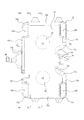
図1は、本発明の第一実施形態に係る貯留槽1Aの流入側を、上方から示す斜視図である。図2は、図1の貯留槽1Aの流出側を、上方から示す斜視図である。貯留槽1Aは、液体が流入する流入口A1と、前記液体が流出する流出口A2と、を有し、流入口A1から流入した前記液体を内部に貯留可能である。
[Storage tank according to the first embodiment of the present invention]
FIG. 1 is a perspective view showing the inflow side of the
図3は、貯留槽1Aを流入側から示す正面図である。また図4は、貯留槽1Aを流出側から示す背面図である。図4に示すように、貯留槽1Aは、底壁11と、底面に対して起立する周壁12と、底面に対して起立する2つの仕切壁13と、を備えている。本実施形態では、貯留槽1Aは、天壁14を備えている。天壁14は、周壁12の上端と繋がっている。これにより、本実施形態では、貯留槽1Aの内部には、底壁11と、周壁12と、天壁14と、で区画された空間が形成されている。なお、本実施形態では、周壁12には、通気口H12が形成されている。通気口H12は、貯留槽1Aの内部空間を外界に通じさせる。これにより、貯留槽1Aの内部が負圧になることを防止する。
FIG. 3 is a front view showing the
図5は、貯留槽1Aを上方から示す平面図である。図6は、貯留槽1Aを下方から示す底面図である。図6に示すように、貯留槽1Aにおいて、周壁12は、流入口A1が形成されている流入口部分12aと、流入口部分12aと対向していると共に流出口A2が形成されている流出口部分12bと、を備えている。本実施形態では、周壁12は、流入口部分12aと、流出口部分12bと、流入口部分12aと隣接する流入側隣接部分12cと、流出口部分12bと隣接する流出側隣接部分12dと、側面部分12eと、を備えている。更に本実施形態では、周壁12は、流入側隣接部分12cと側面部分12eとを繋ぐ流入側隅部分12fと、側面部分12eと流出側隣接部分12dとを繋ぐ流出側隅部分12gと、を備えている。
FIG. 5 is a plan view showing the
図6に示すように、貯留槽1Aでは、底壁11は、周壁12によって区画されている。図5に示すように、天壁14も、底壁11と同様に、周壁12によって区画されている。なお、本実施形態では、天壁14は、2つの開口部A3を有している。開口部A3は、貯留槽1Aの内部空間を外界に通じさせる。また本実施形態では、周壁12は、天壁14の側において、流入側隅部分12f及び流出側隅部分12gのそれぞれの位置において、窪み部12hを有している。
As shown in FIG. 6, in the
図7は、図3のA−A断面図である。図7は、貯留槽1Aの最大断面である。図8は、図3のB−B断面図である。図8は、流入口A1の中心Oaを通る断面である。図9は、図4のC−C断面図である。図9は、流出口A2の中心Obを通る断面である。図7等に示すように、貯留槽1Aは、流入口A1と流出口A2との間を延在している液体通過領域R1と、液体通過領域R1を挟んだ両側のそれぞれの位置に配置されている液体滞留領域R2と、を備える。貯留槽1Aでは、液体通過領域R1は、流入口A1と流出口A2とを結び、流入口A1から流入した液体を流出口A2に案内する。液体通過領域R1は、平面視で曲線状にしたり、ジグザグ状に延在することも可能である。本実施形態では、液体通過領域R1は、図7〜図9に示すように、直線状に延在している。これにより、液体通過領域R1は、流入口A1と流出口A2とを結ぶ液体通過路として最短の経路となる。
7 is a cross-sectional view taken along the line AA in FIG. FIG. 7 is a maximum cross section of the storage tank 1A. 8 is a cross-sectional view taken along the line BB in FIG. FIG. 8 is a cross section passing through the center Oa of the inlet A1. 9 is a cross-sectional view taken along the line CC of FIG. FIG. 9 is a cross section passing through the center Ob of the outlet A2. As shown in FIG. 7 and the like, the
一方、図7等に示すように、2つの液体滞留領域R2は、液体通過領域R1を挟んだ両側のそれぞれの位置にあって、液体通過領域R1と隣接する位置に配置されている。2つの液体滞留領域R2は、それぞれ、流入口A1から流入した液体を滞留させることができる。 On the other hand, as shown in FIG. 7 and the like, the two liquid retention regions R2 are disposed at positions on both sides of the liquid passage region R1 and adjacent to the liquid passage region R1. Each of the two liquid retention regions R2 can retain the liquid flowing in from the inflow port A1.
また、図7等に示すように、貯留槽1Aでは、周壁12の流入口部分12aは、流入口部分12aと隣接する流入側隣接部分12cよりも流出側に窪んでいる。本実施形態では、図7等に示すように、周壁12の流入側隣接部分12cは、2つの流入側隅部分12j及び12iを介して流入口部分12aに繋がっている。
Moreover, as shown in FIG. 7 etc., in the
また、貯留槽1Aでは、周壁12の流出口部分12bは、流出側隣接部分12dよりも流出側に突出している。本実施形態では、図7等に示すように、周壁12の流出側隣接部分12dは、流出口部分12bに繋がっている。
Moreover, in the
図10は、貯留槽1Aの右側面を示す右側面図である。図11は、貯留槽1Aの左側面を示す左側面図である。図10等に示すように、貯留槽1Aでは、流入口A1は、周壁12の流入口部分12a及び流出口部分12bを除く周壁12よりも下側に位置されている。流出口A2も、流入口A1と同様、周壁12の流入口部分12a及び流出口部分12bを除く周壁12よりも下側に位置されている。
FIG. 10 is a right side view showing the right side surface of the
図12は、図5のD−D断面図である。図12は、貯留槽1Aを二分する断面である。図12は、貯留槽1Aの内部における、液体通過領域R1と液体滞留領域R2との内部構造を示す。図13は、図5のE−E断面図である。図13は、貯留槽1Aの内部における、液体滞留領域R2の内部構造を示す。図12に示すように、貯留槽1Aでは、流入口A1は、周壁12の流入口部分12aに形成された流入路P1で構成されている。また流出口A2は、周壁12の流出口部分12bに形成された流出路P2で構成されている。貯留槽1Aでは、液体通過領域R1は、周壁12の流入口部分12aの内面12faと、底壁11のうち、当該底壁11の下側部分11aの内面(底面)11faと、周壁12の流出口部分12bの内面12fbと、で構成されている。貯留槽1Aでは、図12に示すように、液体通過領域R1の底面F1は、平坦な面で構成されている。本実施形態では、液体通過領域R1の底面F1は、周壁12の流入口部分12aの内面12faのうち、当該内面12faの最下端(流入口部分12aの液体流通方向に延在する最も下側の延在端)12fa1と、底壁11の下側部分11aの内面11faのうち、当該内面11faの最下端(下側部分11aの液体流通方向に延在する最も下側の延在端)12fa1と、周壁12の流出口部分12bの内面12fbのうち、当該内面12fbの最下端(流出口部分12bの液体流通方向に延在する最も下側の延在端)最下端12fb1と、で構成されている。
12 is a cross-sectional view taken along the line DD of FIG. FIG. 12 is a cross section that bisects the
なお、図12において、符号12fp1は、流入路P1の最下端(流入路P1の液体流通方向に延在する最も下側の延在端)である。また符号12fp2は、流出口部分12bに形成された流出路P2の最下端(流出路P2の液体流通方向に延在する最も下側の延在端)である。図12等に示すように、貯留槽1Aでは、底壁11の下側部分11aの最下端(底面)11fa1は、下流に向かって下方に傾斜しており、流出口A2は、流入口A1よりも低い位置に設けられている。
In FIG. 12, reference numeral 12fp1 is the lowermost end of the inflow path P1 (the lowermost extending end extending in the liquid flow direction of the inflow path P1). Reference numeral 12fp2 is the lowermost end of the outflow passage P2 formed in the
一方、図7等に示すように、2つの液体滞留領域R2は、それぞれ、平面視において、周壁12のうち、流入口部分12a及び流出口部分12bを除いた周壁12と、液体通過領域R1と、で区画されている。詳細には、2つの液体滞留領域R2は、それぞれ、平面視において、流入側隅部分12iの内面12fiと、流入側隅部12jの内面12fjと、流入側隣接部分12cの内面12fcと、流入側隅部分12fの内面12ffと、側面部分12eの内面12feと、流出側隅部分12gの内面12fgと、流出側隣接部分12dの内面12fdと、液体通過領域R1と、で区画されている。更に、2つの液体滞留領域R2は、それぞれ、図13等に示すように、底壁11のうち、当該底壁11の上側部分11bの内面(底面)11fbと、天壁14の内面(天面)14fと、で構成されている。なお、貯留槽1Aでは、図13に示すように、液体滞留領域R2の底面F2は、平坦な面で構成されている。本実施形態では、液体滞留領域R2の底面F2は、底壁11の上側部分11bの内面11fbで構成されている。
On the other hand, as shown in FIG. 7 and the like, each of the two liquid retention regions R2 includes, in plan view, the
図14は、図5のF−F断面を流入側から示す斜視図である。F−F断面は、天壁14の2つの開口部A3の中心軸を含む平面の断面である。図14に示すように、液体通過領域R1には、溝部Gが配置されている。溝部Gは、流入口A1と流出口A2との間に配置されている。図14等に示すように、貯留槽1Aでは、溝部Gの一部は、底壁11の下側部分11aの内面11faで形作られている。貯留槽1Aでは、底壁11の下側部分11aは、底壁11の上側部分11bに対して窪んでいる。本実施形態では、底壁11の下側部分11aの内面11faは、最深面11fa1と2つの側面11fa2とで構成されている。最深面11fa1は、底壁11のうちの、最も深い面(最下端)である。最深面11fa1は、側面11fa2を介して、底壁11の上側部分11bの内面11fbに繋がっている。最深面11fa1は、側面11fa2に対して液体通過領域R1の延在方向視で曲線からなる曲面で繋がっている。側面11fa2は、上側部分11bの内面11fbに対して液体通過領域R1の延在方向視で曲線からなる曲面で繋がっている。
FIG. 14 is a perspective view showing the FF cross section of FIG. 5 from the inflow side. The FF cross section is a plane cross section including the central axis of the two openings A3 of the
また貯留槽1Aでは、溝部Gの一部は、周壁12の流出口部分12bの内面12fbで形作られている。図10等に示すように、貯留槽1Aでは、周壁12の流出口部分12bは、流出口A2が流出側隣接部分12dよりも下側の位置になるように、下側に延在している。図14に示すように、本実施形態では、周壁12の流出口部分12bの内面12fbは、最深面12fb1と2つの側面11fb2とを含んでいる。最深面12fb1は、側面12fb2に対して液体通過領域R1の延在方向視で曲線からなる曲面で繋がっている。側面12fb2は、底壁11の下側部分11aの側面11fa2と同一平面を構成している。最深面12fb1は、周壁12の流出口部分12bの内面12fbのうちの、最も深い面(最下端)である。最深面12fb1は、底壁11の下側部分11aの最深面11fa1と同一平面を構成している。また最深面12fb1は、側面12fb2を介して、仕切壁13の内面13f1に繋がっている。側面12fb2は、仕切壁13の内面13f1と同一平面を構成している。
In the
更に図8等に示すように、貯留槽1Aでは、溝部Gの一部は、周壁12の流入口部分12aの内面11faで形作られている。図10等に示すように、貯留槽1Aでは、周壁12の流入口部分12aは、流入口A1が流入側隣接部分12cよりも下側の位置になるように、下側に延在している。図8に示すように、本実施形態では、周壁12の流入口部分12aの内面12faは、最深面12fa1と2つの側面11fa2とで構成されている。最深面12fa1は、側面12fa2に対して液体通過領域R1の延在方向視で曲線からなる曲面で繋がっている。側面12fa2は、底壁11の下側部分11aの側面11fa2と同一平面を構成している。図12等に示すように、最深面12fa1は、周壁12の流入口部分12aの内面12faのうちの、最も深い面(最下端)である。最深面12fa1は、底壁11の下側部分11aの最深面11fa1と同一平面を構成している。また図8等に示すように、最深面12fa1は、側面12fa2を介して、流入側隅部分12iの内面12fiに繋がっている。
Further, as shown in FIG. 8 and the like, in the
図9等に示すように、2つの仕切壁13は、流出口A2に向かって延在している。貯留槽1Aでは、流出口A2を確保するように流出口A2に向かって延在している。ここで、「流出口A2を確保する」とは、「流出口A2の開口を閉じない」ことをいう。
As shown in FIG. 9 and the like, the two
また図12に示すように、貯留槽1Aでは、仕切壁13は、当該仕切壁13から前記液体が越流可能な高さH13を有している。本実施形態では、仕切壁13の高さH13は、液体通過領域R1の底面F1からの高さである。これにより、液体通過領域R1を通る液体は、当該液体の水頭が一定以上となると、液体滞留領域R2に流すことができる。
As shown in FIG. 12, in the
また図12等に示すように、貯留槽1Aでは、仕切壁13の高さH13は、流出口A2に向かうに従って高くなる。図12等に示すように、本実施形態では、仕切壁13の頂面13f2は、側面視の断面形状が流出側に向かって凸の曲線からなる曲面である。図12に示すように、本実施形態では、仕切壁13の頂面13f2の曲線は、曲率半径R13で構成されている。
Moreover, as shown in FIG. 12 etc., in the
貯留槽1Aでは、仕切壁13は、周壁12の流出口部分12bの一部として構成されている。仕切壁13は、溝部Gと隣接している位置から起立している。図15は、図5のG−G断面を流入側から示す斜視図である。G−G断面は、周壁12と底壁11との境界を含む平面の断面である。図15等に示すように、貯留槽1Aでは、仕切壁13の内面13f1は、周壁12の流出口部分12bの内面12fbのうち、当該内面12fbの側面12fb2に繋がっていると共に、当該側面12fb2と同一平面を構成している。また貯留槽1Aでは、周壁12の流出口部分12bと隣接する当該周壁12の流出側隣接部分12dの内面12fdは、仕切壁13の頂面13f2に繋がっていると共に、当該仕切壁13の頂面13f2と同一面を形作っている。ここで、「同一面」とは、「滑らかに繋がる連続的な面」をいい、「平面」及び「曲面」のいずれの面も含まれる。
In the
図16は、図5のG−G断面図である。図16に示すように、貯留槽1Aでは、仕切壁13の頂面13f2の端縁部13eは、貯留槽1Aの内部に向かって凸の曲面である。
16 is a cross-sectional view taken along the line GG in FIG. As shown in FIG. 16, in the
また図13に示すように、貯留槽1Aでは、周壁12の流出側隣接部分12dの内面12fdは、側面視の断面形状が流出側に向かって凸の曲線からなる曲面である。図13に示すように、本実施形態では、流出側隣接部分13dの内面13fdは、底壁11側の曲線は大きな曲率半径Rd11で構成されている。本実施形態では、曲率半径Rd11は、仕切壁13の頂面13f2の曲線を形作る曲率半径R13と同一である。一方、天壁14側の曲線は、底壁11側の曲線よりも小さな曲率半径Rd14で構成されている。
As shown in FIG. 13, in the
本願発明者は、鋭意、試験・研究の結果、サイホン排水システムに用いられる貯留槽において、当該貯留槽の流出口付近の液体の水頭を迅速に高めた場合、多くの液体を迅速かつスムーズに流出させることができ、ひいては、サイホン力が発生するまでの時間を短縮できることを見出した。本実施形態に係る貯留槽1Aは、流出口A2付近の液体の水頭を迅速に高めた場合、多くの液体を迅速かつスムーズに流出させることができることに着目してなされたものである。
As a result of diligent and test / research, the inventor of the present application, in the storage tank used in the siphon drainage system, when the liquid head in the vicinity of the outlet of the storage tank is quickly increased, a large amount of liquid can flow out quickly and smoothly. It has been found that the time until the siphon force is generated can be shortened. The
図12等に示すように、本実施形態に係る貯留槽1Aは、液体が流入する流入口A1と、前記液体が流出する流出口A2と、を有し、流入口A1から流入した前記液体を内部に貯留可能な貯留槽である。貯留槽1Aは、底面に対して起立する周壁12と、底面に対して起立する2つの仕切壁13と、を備えており、周壁12は、流入口A1が形成されている流入口部分12aと、流入口部分12aと対向していると共に流出口A2が形成されている流出口部分12bと、を備えている。2つの仕切壁13は、流出口A2に向かって延在している。
As shown in FIG. 12 and the like, the
本実施形態に係る貯留槽1Aによれば、仕切壁13を設けたことにより、矢印D1に示すように、流出口A2への液体の流れを確保しつつ、流出口A2付近の液体の水頭を迅速に高めることができる。流入口A1から流入した前記液体(排水)が少量の場合であっても、本実施形態によれば、貯留槽1A内に仕切壁13を設けたことにより、流出口A2付近の液体の水頭を迅速に高めることができ、結果的に、サイホン起動を発生させ易くなる。例えば、液体が流入口A1から大量に流入する場合であっても、最初の段階において、流出口A2付近に到達する液体は少量である。このように、流出口A2付近の液体が少量であっても、本実施形態によれば、貯留槽1A内に仕切壁13を設けたことにより、流出口A2付近の液体の水頭を迅速に高めることができ、結果的に、サイホン起動を発生させ易くなる。このため、本実施形態に係る貯留槽1Aによれば、多くの液体を迅速かつスムーズに流出させることができる。特に本実施形態のように、サイホン排水システムに対して貯留槽1Aを用いれば、多くの液体を排水する場合であっても、サイホン力が発生するまでの時間を短縮することができる。
According to the
また図12に示すように、本実施形態において、仕切壁13は、当該仕切壁13から前記液体が越流可能な高さH13を有している。この場合、流出口A2付近の液体の水頭が一定以上となると、図15等の矢印D2に示すように、当該流出口A2付近の液体を仕切壁13から逃がすことができる。このため、本実施形態によれば、液体の流れが流出口A2付近で阻害され難く、より迅速かつスムーズな排水が可能になる。
As shown in FIG. 12, in this embodiment, the
また図12に示すように、本実施形態において、仕切壁13の高さH13は、流出口A2に向かうに従って高くなっている。この場合、流出口A2付近の液体の水頭を高めつつ、当該流出口A2から離れるに従って、仕切壁13から逃がす液体の量を増加させることができる。このため、本実施形態によれば、サイホン力が発生するまでの時間の短縮と、スムーズな排水とのバランス(両立)を図ることができる。
Moreover, as shown in FIG. 12, in this embodiment, height H13 of the
また図12に示すように、本実施形態において、流出口A2は、流入口A1よりも低い位置に設けられている。この場合、より迅速かつスムーズな排水が可能になる。このため、本実施形態によれば、サイホン力が発生するまでの時間をより短縮することができる。 Moreover, as shown in FIG. 12, in this embodiment, the outflow port A2 is provided in the position lower than the inflow port A1. In this case, more rapid and smooth drainage is possible. For this reason, according to this embodiment, the time until the siphon force is generated can be further shortened.
また図15等に示すように、本実施形態において、仕切壁13は、周壁12の流出口部分12bの一部として構成されており、周壁12の流出口部分12bと隣接する当該周壁12の流出側隣接部分12dの内面12fdは、仕切壁13の頂面13f2に繋がっていると共に、当該仕切壁13の頂面13f2と同一面を形作っている。この場合、矢印D2に示すように、仕切壁13から逃がした液体を、周壁12の流出側隣接部分12dの内面12fdに沿って更に逃がすことができる。このため、本実施形態によれば、液体の流れが流出口A2付近でより阻害され難く、より迅速かつスムーズな排水が可能となる。
15 and the like, in this embodiment, the
また図16に示すように、本実施形態において、仕切壁13の頂面13f2の端縁部13eは、貯留槽1Aの内部に向かって凸の曲面である。この場合、矢印D2に示すように、流出口A2付近の液体を、仕切壁13から周壁12の流出側隣接部分12dの内面12fdに沿って効率的かつスムーズに逃がすことができる。このため、本実施形態によれば、迅速かつスムーズな排水を効率的に行うことが可能となる。
As shown in FIG. 16, in the present embodiment, the
また図13等に示すように、本実施形態において、周壁12の流出側隣接部分12dの内面12fdは、側面視の断面形状が流出側に向かって凸の曲線からなる曲面である。この場合、矢印D3に示すように、仕切壁13から逃がした液体を、上下方向(縦方向)の対流(循環)を生じさせながら、周壁12の流出側隣接部分12dの内面12fdに沿って更に逃がすことができる。このため、本実施形態によれば、更に迅速かつスムーズな排水が可能となる。
Further, as shown in FIG. 13 and the like, in the present embodiment, the inner surface 12fd of the outflow side
特に図7等に示すように、本実施形態に係る貯留槽1Aは、流入口A1と流出口A2との間を延在している液体通過領域R1と、液体通過領域R1を挟んだ両側のそれぞれの位置に配置されている液体滞留領域R2と、を備えている。この場合、矢印D1及びD2に示すように、液体通過領域R1に液体を流しつつ、当該液体の残りを液体滞留領域R2内に滞留させることができる。このため、本実施形態によれば、液体通過領域R1の延在方向長さの長大化を抑制しつつ、より多くの液体を液体滞留領域R2に貯留することができる。従って、貯留槽1Aによれば、液体の流れが流出口A2付近で阻害され難く、より多くの液体を迅速かつスムーズな排水を一定量だけ連続して行うことが可能になる。加えて、この場合、液体通過領域R1から流れた液体は、矢印D4に示すように、液体通過領域R1と液体滞留領域R2との間で対流(循環)させることができる。このため、本実施形態によれば、液体通過領域R1の延在方向長さの長大化を抑制しつつ、更に多くの液体を迅速かつスムーズに排水することができる。更にこの場合、液体通過領域R1から流れた液体が、液体通過領域R1と液体滞留領域R2との間で対流することから、貯留槽1Aの内部に汚れが付着し難くなる。これにより、貯留槽1Aの洗浄に必要な作業の回数を削減することができる。
In particular, as shown in FIG. 7 and the like, the
さらに、本実施形態によれば、液体滞留領域R2は、液体通過領域R1を挟んだ両側のそれぞれの位置に配置されているので、液体滞留領域R2の容積を確保するためには、例えば、当該液体滞留領域R2が延在する方向の寸法(面積)を大きくするだけで済み、液体滞留領域R2の高さ、ひいては貯留槽1Aの高さを高くしないようにすることができる。従って、本実施形態のように、例えば、貯留槽1Aを、液体通過領域R1を挟んだ両側で液体滞留領域R2が延在する方向を水平方向とし、周壁12の立設方向が鉛直方向となるように、床スラブ102等に設置すれば、床下空間Sの高さを大きく確保することなく、多くの液体を迅速かつスムーズに排水することもできる。ここで、「貯留槽1Aの高さ」とは、貯留槽1Aの鉛直方向の高さ(寸法)である。言い換えれば、貯留槽1Aの周壁12の立設方向の高さ(寸法)である。
Furthermore, according to the present embodiment, the liquid staying region R2 is disposed at each position on both sides of the liquid passage region R1, so in order to ensure the volume of the liquid staying region R2, for example, It is only necessary to increase the dimension (area) in the direction in which the liquid retention region R2 extends, and the height of the liquid retention region R2 and hence the height of the
上記の観点から、より具体的に例えば、本実施形態では、貯留槽1Aの高さは、貯留槽1Aの幅より低くすることができ、好ましくは、貯留槽1Aの高さは、貯留槽1Aの幅の1/2以下であり、より好ましくは、貯留槽1Aの高さは、貯留槽1Aの幅の1/3以下である。ここで、「貯留槽1の幅」とは、互いに対向する貯留槽1Aの周壁12のうち、貯留槽1Aの高さ方向及び液体通過領域R1の延在方向に対して直交する方向の、2つの周壁12の間の最大幅である。即ち、図7を参照すれば、図面上下方向に配置された貯留槽1Aにおける2つの周壁(側壁)12eの外面の間の幅(寸法)である。
From the above viewpoint, more specifically, for example, in the present embodiment, the height of the
また図7等に示すように、貯留槽1Aでは、周壁12の流入口部分12aは、当該流入口部分12aと隣接する当該周壁12の流入側隣接部分12cよりも流出側に窪んでいる。この場合、貯留槽1A内を流れる液体は、液体の流出方向に戻り易くなる。このため、より迅速かつスムーズに排水することができる。特に、本実施形態では、液体滞留領域R2が液体通過領域R1と隣接する位置に配置されているので、液体通過領域R1から流れた液体は、当該液体通過領域R1に戻り易くなる。即ち、本実施形態では、液体通過領域R1と液体滞留領域R2との間で効率的に対流させることができる。このため、本実施形態によれば、液体通過領域R1を通して多くの液体を、より迅速かつスムーズに排水することができる。また本実施形態では、貯留槽1Aの内部に汚れが更に付着し難くなる。これにより、貯留槽1Aの洗浄に必要な作業の回数を更に削減することができる。
Further, as shown in FIG. 7 and the like, in the
また図15等に示すように、仕切壁13は、溝部Gと隣接している位置から起立している。本実施形態では、溝部Gは、液体通過領域R1に配置されている。この場合、少量の液体であっても当該液体を溝部Gにより迅速に集めることができる。このため、更に迅速かつスムーズな排水が可能になる。本実施形態では、仕切壁13は、液体通過領域R1に配置された溝部Gと隣接している位置から起立している。この場合、少量の液体であっても当該液体を液体通過領域R1に迅速に集めることができる。このため、本実施形態によれば、液体通過領域R1通して多くの液体を、更に迅速かつスムーズに排水することができる。特に、この場合、仕切壁13は、液体通過領域R1に配置された溝部Gと隣接している位置から起立しているため、流出口A2付近の液体の水頭をより迅速に高めることができる。このため、本実施形態によれば、液体通過領域R1を通して多くの液体を、更に一層迅速かつスムーズに排水することができる。
Further, as shown in FIG. 15 and the like, the
また図7等に示すように、貯留槽1Aでは、周壁12の内面12fのうち、平面視で貯留槽1Aの内部に隅部を形作る当該周壁12の内面12fは、平面視の輪郭形状が曲線からなる曲面である。本実施形態では、例えば、流入側隅部分12iの内面12fi、流入側隅部分12jの内面12fj及び流入側隅部分12fの内面12ff、流出側隅部分12gの内面12fgは、それぞれ、平面視の輪郭形状が曲線からなる曲面である。この場合、液体通過領域R1から流れた液体を、液体通過領域R1と液体滞留領域R2との間でより効率的に対流させることができる。従って、本実施形態によれば、多くの液体をより一層スムーズに排水することができると共に、貯留槽1Aの洗浄に必要な作業の回数を更に一層削減することができる。
Further, as shown in FIG. 7 and the like, in the
ところで、本願発明者は、鋭意、試験・研究の結果、サイホン排水システムに用いられる貯留槽において、当該貯留槽の流出口付近に液体を集めた場合も、多くの液体を迅速かつスムーズに流出させることができ、ひいては、サイホン力が発生するまでの時間を短縮できることを見出した。本実施形態に係る貯留槽1Aは、流出口A2付近に液体を集めた場合、多くの液体を迅速かつスムーズに流出させることができることに着目してなされたものである。
By the way, as a result of diligent and test / research, the inventor of the present application causes a large amount of liquid to flow out quickly and smoothly even when liquid is collected near the outlet of the storage tank used in the siphon drainage system. As a result, it has been found that the time until the siphon force is generated can be shortened. The
貯留槽1Aでは、周壁12の流出口部分12bは、周壁12の前記流出口部分12bと隣接する当該周壁12の流出側隣接部分12dよりも流出側に突出している。この場合、流出口A2付近に液体を集め易い構造となる。このため、本実施形態によれば、多くの液体を迅速かつスムーズに流出させることができる。特に本実施形態のように、サイホン排水システムに対して貯留槽1Aを用いれば、多くの液体を排水する場合であっても、サイホン力が発生するまでの時間を短縮することができる。
In the
図17は、図5のH−H断面図である。H−H断面は、周壁12の流出側隣接部分12dの上端を含む平面の断面である。図17に示すように、貯留槽1Aでは、周壁12の流出口部分12bの内面12fbは、液体流通方向視の断面形状がレーストラック形状である。この場合、流出口A2付近に液体をより集め易い構造となる。本実施形態では、レーストラック形状は、横方向(水平方向)に延びる偏平な形状である。例示的なレーストラック形状としては、片側に1つの中心O1が配置された片側単心円のレーストラック形状、片側に2つの中心O1及び中心O2が配置された片側二心円のレーストラック形状、片側に3つの中心O1、中心O2及び中心O3が配置された片側三心円のレーストラック形状が挙げられる。更に片側三心円のレーストラック形状としては、3つの中心O1〜O3が整列した片側正三心円のレーストラック形状、2つの中心O1及び中心O3との間の1つの中心O2が外側に配置された片側鋭三心円のレーストラック形状、2つの中心O1及び中心O3との間の1つの中心O2が内側に配置された鈍三心円のレーストラック形状が挙げられる。本実施形態では、流出口A2の断面形状は、片側鋭三心円のレーストラック形状に類似する形状である。なお、本実施形態では、1つの中心O2を挟んだ、2つの中心O1及び中心O2が非整列であって、A−B間は直線である。またそれ以外の間は曲線である。
17 is a cross-sectional view taken along the line HH in FIG. The HH cross section is a plane cross section including the upper end of the outflow side
特に、貯留槽1Aでは、図7等に示すように、周壁12の流出口部分12bの内面12fbは、流出口A2に向かうに従って先細りする曲面を含んでいる。この場合、流出口A2付近に液体をより集め易い構造となる。
In particular, in the
ところで、図16に示すように、貯留槽1Aでは、液体滞留領域R2の底面F2は、液体通過領域R1の延在方向視で、液体通過領域R1に向かうに従って下方に傾斜し、当該液体通過領域R1の底面F1に繋がる平面である。この場合、液体滞留領域R2の液体は、当該液体滞留領域R2の底面F2を伝って、液体通過領域R1に流れ込み易くなる。このため、本実施形態によれば、液体通過領域R1を通して多くの液体を、よりスムーズに排水することができる。本実施形態では、液体滞留領域R2の底面F2は、水平軸(図16では、水平面を液体通過領域R1の延在方向視したときに現れる直線Oyで示す。)に対して角度θ11bで傾斜している。角度θ11bは、貯留槽1の内容量、大きさ等に応じて、適宜設定することができる。角度θ11bとしては、例えば、0.5°〜5°の角度とすることができる。角度θ11bが0.5°未満の場合、排水の対流を形成するのに効果が薄くなる。また角度θ11bが5°以上の場合、傾斜がきつくなりすぎることから、液体が流出口A2に入りきらずに水が溢れた場合、溢れた液体がうまく液体滞留領域R2に流れていかない。
Incidentally, as shown in FIG. 16, in the
ところで、貯留槽1Aでは、図16に示すとおり、2つの液体滞留領域R2の底面F2は、互いに接近するに従って下方に傾斜している。この場合、2つの液体滞留領域R2の底面F2の下端を直結すれば、液体通過領域R1は、2つの底面F2の直結部分を溝底とするV溝とすることができる。或いは、2つの液体滞留領域R2の底面F2の下端を平面を介して連結すれば、液体通過領域R1は、前記平面を溝底とする台形V溝とすることもできる。これらの液体通過領域R1の底面F1はいずれも2つの液体滞留領域R2の底面F2と同一の高さ位置にある。
Incidentally, in the
これに対し、図12等に示すように、貯留槽1Aでは、液体通過領域R1の底面F1は、液体滞留領域R2の底面F2よりも低い位置に配置されている。この場合、多くの液体を液体通過領域R1に集めることができる。このため、本実施形態によれば、液体通過領域R1を通して多くの液体を、よりスムーズに排水することができる。本実施形態では、液体通過領域R1に溝部Gを配置している。流出口A2の最下端12fP2が液体滞留領域R2の底面F2よりも低い位置に配置されている。
On the other hand, as illustrated in FIG. 12 and the like, in the
また図12〜図16等に示すように、本実施形態では、少なくとも液体滞留領域R2における周壁12の内面12fは、周壁12の延在方向視の断面形状が貯留槽1Aの内部から外向きに凸の曲線からなる曲面である。この場合、液体通過領域R1から流れた液体は、上下方向(縦方向)の対流(循環)が生じながら、周壁12の流出側隣接部分12dの内面12fdに沿って更に逃げる。このため、本実施形態によれば、液体通過領域R1と液体滞留領域R2との間の対流をより効率的に行うことができる。従って、本実施形態によれば、多くの液体をより一層スムーズに排水することができると共に、貯留槽1Aの洗浄に必要な作業の回数を更に一層削減することができる。
As shown in FIGS. 12 to 16 and the like, in this embodiment, at least the
また本実施形態では、液体通過領域R1は、図3及び図4に示すように、流出口A2が、液体の流通方向視(液体通過領域R1の延在方向視)で、流入口A1の少なくとも一部と一直線上に重なるように整列されている。 In the present embodiment, as shown in FIGS. 3 and 4, the liquid passage region R <b> 1 is configured such that the outlet A <b> 2 is at least the inlet A <b> 1 in the liquid flow direction view (the liquid passage region R <b> 1 extension direction view). It is aligned so as to overlap with a part.
図3を参照すると、流入口A1及び流出口A2の整列に関する具体例としては、例えば、以下の、(1)〜(3)のいずれかを組み合わせる方法が挙げられる。
(1)流入口A1の中心Oaと、流出口1bの中心Obと、を、液体通過領域R1の延在方向視で、同一の鉛直線Oz上に整列させる。
(2)流入口A1の内径の大きさ(流入口A1の半径raの大きさ)と、流出口A2の内径の大きさ(流出口A2の半径rbの大きさ)と、を調整する。
(3)流入口A1の中心Oaと、流出口A2の中心Obとの、鉛直方向(鉛直線Ozの方向)の間隔ΔZを調整する。
Referring to FIG. 3, as a specific example of the alignment of the inlet A1 and the outlet A2, for example, a method of combining any of the following (1) to (3) may be mentioned.
(1) The center Oa of the inflow port A1 and the center Ob of the outflow port 1b are aligned on the same vertical line Oz as viewed in the extending direction of the liquid passage region R1.
(2) The size of the inner diameter of the inlet A1 (the size of the radius ra of the inlet A1) and the size of the inner diameter of the outlet A2 (the size of the radius rb of the outlet A2) are adjusted.
(3) The interval ΔZ in the vertical direction (the direction of the vertical line Oz) between the center Oa of the inlet A1 and the center Ob of the outlet A2 is adjusted.
本実施形態では、(1)〜(3)の全ての方法を使用して、流出口A2が、液体通過領域Rの延在方向視)で、流入口A1の少なくとも一部と一直線上に重なるように整列させている。特に、図3に示すように、本実施形態では、(2)において、流出口A2の内径の大きさが流入口A1の内径の大きさよりも小さくなるように設定している。これにより、流出口A2から流出される液体の量は、流入口A1から流入する液体の量に比べて小さくなる。また本実施形態では、図3に示すように、(3)において、流入口A1の中心Oaと、流出口A2の中心Obとは、流入口A1の開口内下端部に、流出口A2の開口内上端が重なるように、鉛直方向の間隔ΔZを調整している。 In this embodiment, using all the methods (1) to (3), the outlet A2 overlaps with at least a part of the inlet A1 in a straight line when viewed in the extending direction of the liquid passage region R). Are aligned. In particular, as shown in FIG. 3, in this embodiment, in (2), the inner diameter of the outlet A2 is set to be smaller than the inner diameter of the inlet A1. As a result, the amount of liquid flowing out from the outlet A2 becomes smaller than the amount of liquid flowing in from the inlet A1. Moreover, in this embodiment, as shown in FIG. 3, in (3), the center Oa of the inflow port A1 and the center Ob of the outflow port A2 are the opening inside the opening A2 and the opening of the outflow port A2. The vertical interval ΔZ is adjusted so that the inner upper ends overlap.
[本発明の第2実施形態に係る貯留槽]
図18は、本発明の第二実施形態に係る貯留槽1Bの流入側を、上方から示す斜視図である。本実施形態では、周壁12は、液体通過領域R1と、液体通過領域R1の両側に配置された2つの液体滞留領域R2とを取り囲んで、貯留槽1Bの外形形状をバタフライ形(H形)に形作っている。本実施形態では、仕切壁13は、周壁12と異なる壁である。
[Storage tank according to the second embodiment of the present invention]
FIG. 18 is a perspective view showing the inflow side of the
上述したところは、本発明の例示的な実施形態を説明したものであり、特許請求の範囲を逸脱しない範囲で様々な変更を行うことができる。例えば、貯留槽1は、樹脂による射出成形によって一体に製造することができる。特に貯留槽1Aは、ブロー成形することができる。但し、貯留槽1の製造方法は、射出成形に限定されない。貯留槽1には、周壁12の上端に形成された天壁14の有無は問わない。また排水システム100の構成は、本実施形態の構成に限定されるものではない。例えば、器具排水管120及びサイホン排水管130は、それぞれの上流側部分(横引き管)と下流側部分(竪管)とが一体の排水管で説明したが、上流側部分(横引き管)と下流側部分(竪管)とを別体の排水管とし、これらの排水管を互いに接続させることにより、器具排水管120又はサイホン排水管130とすることができる。また、上述した貯留槽1A又は貯留槽1Bに採用された様々な構成は、相互に適宜、置き換えることができる。
What has been described above describes exemplary embodiments of the present invention, and various modifications can be made without departing from the scope of the claims. For example, the
1A:貯留槽, 1B:貯留槽, A1:流入口, P1:流入路, A2:流出口, P2:流出路, 1c:通気口, 11:底壁, 11a:底壁の下側部分, 11fa:底壁の下側部分の内面, 11fa1:底壁の下側部分の最深面, 11fa2:底壁の下側部分の側面, 11b:底壁の上側部分, 11fb:底壁の上側部分の内面, 12:周壁, 12a:周壁の流入口部分, 12fa:周壁の流入口部分の内面, 12fa1:周壁の流入口部分の内面の最深面, 12fa2:周壁の流入口部分の内面の側面, 12b:周壁の流出口部分, 12fb:周壁の流出口部分の内面, 12fb1:周壁の流出口部分の内面の最深面, 12fb2:周壁の流出口部分の内面の側面, 12c:周壁の流入口隣接部分, 12fc:周壁の流入口隣接部分の内面, 12d:周壁の流出口隣接部分, 12fd:周壁の流出口隣接部分の内面, 12e:周壁の側面部分, 12fe:周壁の側面部分の内面, 12f:周壁の流入側隅部分, 12ff:周壁の流入側隅部分の内面, 12i:周壁の流入側隅部分, 12fi:周壁の流入側隅部分の内面, 12j:周壁の流入側隅部分, 12fj:周壁の流入側隅部分の内面, 12g:周壁の流出側隅部分, 12fg:周壁の流出側隅部分の内面, 13:仕切壁, 13f1:仕切壁の側面, 13f2:仕切壁の頂面, 13e:仕切壁の頂面の端縁部, R1:液体通過領域, G:溝部, F1:液体通過領域の底面, R2:液体滞留領域, F2:液体滞留領域の底面, 100:排水システム, 101:床部材, 102:床スラブ, 110:水廻り器具, 120:器具排水管, 120a:器具排水管の上流側部分, 120b:器具排水管の下流側部分, 121:排水トラップ, 130:サイホン排水管, 130a:サイホン排水管の横引き管, 130b:サイホン排水管の竪管, 140:管継手, 150:立て管, S:床下空間 1A: Reservoir, 1B: Reservoir, A1: Inlet, P1: Inlet, A2: Outlet, P2: Outlet, 1c: Vent, 11: Bottom wall, 11a: Lower part of bottom wall, 11fa : Inner surface of lower part of bottom wall, 11fa1: deepest surface of lower part of bottom wall, 11fa2: side surface of lower part of bottom wall, 11b: upper part of bottom wall, 11fb: inner surface of upper part of bottom wall , 12: peripheral wall, 12a: inlet portion of the peripheral wall, 12fa: inner surface of the inlet portion of the peripheral wall, 12fa1: deepest surface of the inner surface of the inlet portion of the peripheral wall, 12fa2: side surface of the inner surface of the inlet portion of the peripheral wall, 12b: 12fb: inner surface of the peripheral wall outlet portion, 12fb1: deepest surface of the inner surface of the peripheral wall outlet portion, 12fb2: side surface of the inner surface of the peripheral wall outlet portion, 12c: adjacent portion of the peripheral wall inlet port, 12fc 12d: inner surface of the peripheral wall outlet adjacent portion, 12e: inner surface of the peripheral wall outlet adjacent portion, 12e: side surface portion of the peripheral wall, 12fe: inner surface of the side surface portion of the peripheral wall, 12f: inflow of the peripheral wall 12ff: inner surface of inflow side corner portion of peripheral wall, 12fi: inner surface of inflow side corner portion of peripheral wall, 12j: inflow side corner portion of peripheral wall, 12fj: inflow side of peripheral wall 12g: Outer side corner portion of the peripheral wall, 12fg: Inner surface of the outer side corner portion of the peripheral wall, 13: Partition wall, 13f1: Side surface of the partition wall, 13f2: Top surface of the partition wall, 13e: Edge of top surface, R1: Liquid passage region, G: Groove, F1: Bottom surface of liquid passage region, R2: Liquid retention region, F2: Bottom surface of liquid retention region, 100: Drainage system, 101: Floor Material: 102: floor slab, 110: watering equipment, 120: equipment drain pipe, 120a: upstream part of the equipment drain pipe, 120b: downstream part of the equipment drain pipe, 121: drain trap, 130: siphon drain pipe, 130a: Horizontally drawn pipe of siphon drain pipe, 130b: Saddle pipe of siphon drain pipe, 140: Pipe joint, 150: Stand pipe, S: Under floor space
Claims (12)
底面に対して起立する周壁と、前記底面に対して起立する仕切壁と、を備えており、
前記周壁は、前記流入口が形成されている流入口部分と、前記流入口部分と対向していると共に前記流出口が形成されている流出口部分と、を備えており、
前記仕切壁は、前記流出口に向かって延在している、貯留槽。 A storage tank having an inflow port through which a liquid flows in and an outflow port through which the liquid flows out, and capable of storing the liquid flowing in from the inflow port;
A peripheral wall that stands up with respect to the bottom surface, and a partition wall that stands up with respect to the bottom surface,
The peripheral wall includes an inlet portion where the inlet is formed, and an outlet portion facing the inlet portion and where the outlet is formed,
The said partition wall is a storage tank extended toward the said outflow port.
前記周壁の前記流出口部分と隣接する当該周壁の流出側隣接部分の内面は、前記仕切壁の頂面に繋がっていると共に、当該仕切壁の頂面と同一面を形作っている、請求項1乃至4のいずれか1項に記載の貯留槽。 The partition wall is configured as a part of the outlet portion of the peripheral wall,
The inner surface of the outflow side adjacent portion of the peripheral wall adjacent to the outlet portion of the peripheral wall is connected to the top surface of the partition wall and forms the same surface as the top surface of the partition wall. The storage tank of any one of thru | or 4.
Priority Applications (3)
| Application Number | Priority Date | Filing Date | Title |
|---|---|---|---|
| JP2018092734A JP7017466B2 (en) | 2018-05-14 | 2018-05-14 | Storage tank |
| TW108116355A TWI717731B (en) | 2018-05-14 | 2019-05-13 | Storage tank (1) |
| CN201910396990.8A CN110485520B (en) | 2018-05-14 | 2019-05-14 | Storage tank |
Applications Claiming Priority (1)
| Application Number | Priority Date | Filing Date | Title |
|---|---|---|---|
| JP2018092734A JP7017466B2 (en) | 2018-05-14 | 2018-05-14 | Storage tank |
Publications (2)
| Publication Number | Publication Date |
|---|---|
| JP2019199683A true JP2019199683A (en) | 2019-11-21 |
| JP7017466B2 JP7017466B2 (en) | 2022-02-08 |
Family
ID=68546175
Family Applications (1)
| Application Number | Title | Priority Date | Filing Date |
|---|---|---|---|
| JP2018092734A Active JP7017466B2 (en) | 2018-05-14 | 2018-05-14 | Storage tank |
Country Status (3)
| Country | Link |
|---|---|
| JP (1) | JP7017466B2 (en) |
| CN (1) | CN110485520B (en) |
| TW (1) | TWI717731B (en) |
Citations (5)
| Publication number | Priority date | Publication date | Assignee | Title |
|---|---|---|---|---|
| JP2009275438A (en) * | 2008-05-15 | 2009-11-26 | Bridgestone Corp | Reservoir and siphon drainage system |
| JP2010270465A (en) * | 2009-05-20 | 2010-12-02 | Bridgestone Corp | Storage tank for siphon drainage system, and siphon drainage system |
| JP2011256557A (en) * | 2010-06-07 | 2011-12-22 | Bridgestone Corp | Siphon drainage system |
| JP2016108749A (en) * | 2014-12-02 | 2016-06-20 | 株式会社ブリヂストン | Storing tank, siphonic drainage system and outflow pipe connecting member |
| JP2017190626A (en) * | 2016-04-14 | 2017-10-19 | 株式会社ブリヂストン | Siphon drainage system |
Family Cites Families (5)
| Publication number | Priority date | Publication date | Assignee | Title |
|---|---|---|---|---|
| JP2008019642A (en) * | 2006-07-13 | 2008-01-31 | Bridgestone Corp | Storage part for siphon draining system |
| JP2008127837A (en) * | 2006-11-20 | 2008-06-05 | Bridgestone Corp | Siphon drainage system and structure of vent pipe for use in it |
| JP5085949B2 (en) * | 2007-01-29 | 2012-11-28 | 株式会社ブリヂストン | Siphon drainage system |
| JP5642424B2 (en) * | 2010-05-19 | 2014-12-17 | 株式会社ブリヂストン | Cleaning jig |
| JP6454526B2 (en) * | 2014-12-02 | 2019-01-16 | 株式会社ブリヂストン | Storage tank |
-
2018
- 2018-05-14 JP JP2018092734A patent/JP7017466B2/en active Active
-
2019
- 2019-05-13 TW TW108116355A patent/TWI717731B/en active
- 2019-05-14 CN CN201910396990.8A patent/CN110485520B/en active Active
Patent Citations (5)
| Publication number | Priority date | Publication date | Assignee | Title |
|---|---|---|---|---|
| JP2009275438A (en) * | 2008-05-15 | 2009-11-26 | Bridgestone Corp | Reservoir and siphon drainage system |
| JP2010270465A (en) * | 2009-05-20 | 2010-12-02 | Bridgestone Corp | Storage tank for siphon drainage system, and siphon drainage system |
| JP2011256557A (en) * | 2010-06-07 | 2011-12-22 | Bridgestone Corp | Siphon drainage system |
| JP2016108749A (en) * | 2014-12-02 | 2016-06-20 | 株式会社ブリヂストン | Storing tank, siphonic drainage system and outflow pipe connecting member |
| JP2017190626A (en) * | 2016-04-14 | 2017-10-19 | 株式会社ブリヂストン | Siphon drainage system |
Also Published As
| Publication number | Publication date |
|---|---|
| JP7017466B2 (en) | 2022-02-08 |
| CN110485520B (en) | 2021-02-12 |
| TWI717731B (en) | 2021-02-01 |
| CN110485520A (en) | 2019-11-22 |
| TW202003970A (en) | 2020-01-16 |
Similar Documents
| Publication | Publication Date | Title |
|---|---|---|
| TWI672418B (en) | Storage tank | |
| JP5619478B2 (en) | Siphon drainage system | |
| JP2019199683A (en) | Storage tank | |
| JP4617415B2 (en) | Drain trap | |
| JP2019199682A (en) | Storage tank | |
| JP7429635B2 (en) | siphon drainage system | |
| JP7429634B2 (en) | siphon drainage system | |
| JP6971128B2 (en) | Storage tank | |
| JP6503263B2 (en) | Drainage structure of bathroom | |
| JP2007205147A (en) | Overflow device | |
| JP2017089326A (en) | Storage tank and syphon drainage system | |
| JP6397260B2 (en) | Join | |
| JP7393320B2 (en) | siphon drainage system | |
| JP6384912B2 (en) | Flush toilet | |
| JP7421305B2 (en) | How to clean pipe fittings, pipes, and drain pipes | |
| JP7436178B2 (en) | drain pipe structure | |
| JP7328118B2 (en) | Drain cleaning method | |
| JP6843368B2 (en) | Flush toilet | |
| JP6185705B2 (en) | Temporary storage tank | |
| JP2023179301A (en) | Piping structure | |
| TW202134505A (en) | Muffler | |
| JP2022091507A (en) | Storage tank | |
| JP2023077897A (en) | piping structure | |
| JP2023179302A (en) | Piping structure | |
| JP2023077901A (en) | piping structure |
Legal Events
| Date | Code | Title | Description |
|---|---|---|---|
| A621 | Written request for application examination |
Free format text: JAPANESE INTERMEDIATE CODE: A621 Effective date: 20201217 |
|
| A131 | Notification of reasons for refusal |
Free format text: JAPANESE INTERMEDIATE CODE: A131 Effective date: 20211019 |
|
| A521 | Request for written amendment filed |
Free format text: JAPANESE INTERMEDIATE CODE: A523 Effective date: 20211215 |
|
| TRDD | Decision of grant or rejection written | ||
| A01 | Written decision to grant a patent or to grant a registration (utility model) |
Free format text: JAPANESE INTERMEDIATE CODE: A01 Effective date: 20220125 |
|
| A61 | First payment of annual fees (during grant procedure) |
Free format text: JAPANESE INTERMEDIATE CODE: A61 Effective date: 20220127 |
|
| R150 | Certificate of patent or registration of utility model |
Ref document number: 7017466 Country of ref document: JP Free format text: JAPANESE INTERMEDIATE CODE: R150 |