JP2007205147A - Overflow device - Google Patents
Overflow device Download PDFInfo
- Publication number
- JP2007205147A JP2007205147A JP2006053760A JP2006053760A JP2007205147A JP 2007205147 A JP2007205147 A JP 2007205147A JP 2006053760 A JP2006053760 A JP 2006053760A JP 2006053760 A JP2006053760 A JP 2006053760A JP 2007205147 A JP2007205147 A JP 2007205147A
- Authority
- JP
- Japan
- Prior art keywords
- overflow
- hole
- elbow
- water
- flow
- Prior art date
- Legal status (The legal status is an assumption and is not a legal conclusion. Google has not performed a legal analysis and makes no representation as to the accuracy of the status listed.)
- Pending
Links
- XLYOFNOQVPJJNP-UHFFFAOYSA-N water Substances O XLYOFNOQVPJJNP-UHFFFAOYSA-N 0.000 claims abstract description 73
- 238000012856 packing Methods 0.000 claims description 23
- 238000003780 insertion Methods 0.000 claims description 9
- 230000037431 insertion Effects 0.000 claims description 9
- 238000009825 accumulation Methods 0.000 description 7
- 238000013461 design Methods 0.000 description 6
- 239000011324 bead Substances 0.000 description 2
- 238000010276 construction Methods 0.000 description 1
- 230000003111 delayed effect Effects 0.000 description 1
- 238000000034 method Methods 0.000 description 1
- 238000012545 processing Methods 0.000 description 1
- 230000000717 retained effect Effects 0.000 description 1
- 230000002441 reversible effect Effects 0.000 description 1
- 238000007789 sealing Methods 0.000 description 1
- 229920003002 synthetic resin Polymers 0.000 description 1
- 239000000057 synthetic resin Substances 0.000 description 1
- 238000013022 venting Methods 0.000 description 1
- 239000003643 water by type Substances 0.000 description 1
Images




Landscapes
- Sink And Installation For Waste Water (AREA)
Abstract
Description
本発明は、洗面台、浴槽、流し台などにおけるあふれ出し防止をするオーバーフロー装置に関するものである。 The present invention relates to an overflow device for preventing overflow in a wash basin, a bathtub, a sink, and the like.
従来、洗面台、浴槽、流し台などのオーバーフロー装置は、オーバーフロー水が少量で、且つ徐々のオーバーフローである場合には、スムーズに流れているが、多量、且つ急激な増量となると、オーバーフロー孔が堰となって流れを遅延させ、また閉塞してしまう結果となっていた。況して、オーバーフロー孔が小さいと、尚更であった。 Conventionally, overflow devices such as wash basins, bathtubs, sinks, etc., flow smoothly when the amount of overflow water is small and gradually overflows. As a result, the flow was delayed and blocked. It was even more so when the overflow hole was small.
そこで、オーバーフロー孔を可能の限り大きくすることが考えられるけれど、それは意匠的機能構造からして芳しくなく、大きさにも限度がある。また、構造上より、オーバーフロー孔に接続するオーバーフロー排出管には空気溜りができてしまいやすく、それが流れを停滞し、そして更には閉塞させてしまうことになっていた。 Therefore, it is conceivable to make the overflow hole as large as possible, but it is not good from the viewpoint of the design functional structure, and the size is limited. In addition, due to the structure, the overflow discharge pipe connected to the overflow hole is likely to retain air, which stagnates and further blocks the flow.
特に、オーバーフロー孔を小さくした洗面台などでは、洗面ボールが合成樹脂でできているので、頑丈にするために肉厚を厚くした結果、オーバーフロー孔は、その孔径より孔奥行き長さが長くなり、オーバーフロー孔裏面のオーバーフロー排出管の取付部分に、空気溜りを形成されがちになり、オーバーフロー水の流れに障害となっていた。 In particular, in a washstand with a small overflow hole, the wash ball is made of synthetic resin, and as a result of increasing the thickness to make it sturdy, the overflow hole has a longer hole depth than its hole diameter, An air reservoir tends to be formed in the attachment portion of the overflow discharge pipe on the back surface of the overflow hole, which hinders the flow of overflow water.
そこで、オーバーフロー孔にオーバーフロー排水管を接続するのにオーバーフローエルボで繋ぐものの場合、多量のオーバーフロー水がオーバーフロー孔に流入すると、該オーバーフローエルボに空気が封入されてしまって、オーバーフロー水の流れを悪くしている。これを解決すべく、オーバーフローエルボの上側部にエプロンへと連設するエアベント(空気抜き口)を備えたものがある。(特許文献1) Therefore, in the case of connecting the overflow drain pipe to the overflow hole with an overflow elbow, if a large amount of overflow water flows into the overflow hole, air is sealed in the overflow elbow, which makes the overflow water flow worse. ing. In order to solve this problem, there are some which have an air vent (air vent) connected to the apron on the upper side of the overflow elbow. (Patent Document 1)
また、オーバーフロー孔の孔径を大きくすることは、洗面ボールの外観を悪くし、だからといって、孔径を小さくすれば排水効率が悪くなるので、これを解決すべく、オーバーフロー孔に接続するオーバーフロー排出管を繋ぐオーバーフローエルボにオーバーフロー孔より通水断面積の大きい水室を形成し、ここにオーバーフロー水を充満させた上で、水室の通水断面積より狭く狭窄した流出口によって、オーバーフロー水の流れを一且絞って流出させ、この流れがベンチュリー管の作用をし、増速されるというものがある。(特許文献2) Increasing the hole diameter of the overflow hole deteriorates the appearance of the wash bowl. However, if the hole diameter is reduced, the drainage efficiency is deteriorated. To solve this problem, an overflow discharge pipe connected to the overflow hole is connected. A water chamber having a larger cross-sectional area than the overflow hole is formed in the overflow elbow, and after overflow water is filled there, the flow of overflow water is unified by the outlet narrowed and narrower than the cross-sectional area of the water chamber. There is one that is squeezed out and this flow acts as a Venturi tube and is accelerated. (Patent Document 2)
従来には、オーバーフロー孔に接続するオーバーフロー排水管を繋ぐオーバーフローエルボに溜る空気を空気抜きするエアベントなどを設けたものがあって、一応は、オーバーフロー水の支障のない流出を可能とするものであるが、空気抜き口よりオーバーフロー水の溢れ出しを起こし、これを防止するため、空気抜き口にエアベントなど連設してエプロンに至らしめている。
このように空気抜き口に連設するエアベントなどはエプロンに露出させ、意匠的に見栄えよくなく、更にこれらを付設することによって、構造上、部品点数が増えてしまうことになった。
その上、オーバーフロー孔がより小さい孔径になると、オーバーフロー孔の閉塞現象を起すことになって不都合である。Conventionally, there has been provided an air vent or the like for venting the air accumulated in the overflow elbow connecting the overflow drain pipe connected to the overflow hole. For the time being, the overflow water can be discharged without any trouble. In order to prevent overflowing of overflow water from the air vent, an air vent is connected to the air vent to reach the apron.
As described above, the air vent connected to the air vent port is exposed to the apron and does not look good in design, and the addition of these also increases the number of parts in the structure.
In addition, if the overflow hole has a smaller diameter, the overflow hole is blocked, which is inconvenient.
だからといって、オーバーフロー孔の孔径の小さいものに対応できるように、オーバーフローエルボにオーバーフロー孔の孔径より大きな通水断面積を持つ水室を構成し、この水室にオーバーフロー孔の孔径より小さい流出口を設け、ここで流れを一且絞って流出することによってベンチュリー管作用をさせ、流れの増速をさせるというものである。しかし、オーバーフロー孔より大きな通水断面積の水室を設けることは、これにオーバーフロー水が充満する前に空気の溜る空気溜りを生ずることの根源となって、水室にオーバーフロー水が充満できず、況しては空気溜りでオーバーフロー水が保留されてしまって、流れによる流速が加わらないのでベンチュリー管作用を生じることなく、流れを逆に減速させ、流れなくしてしまうことになっていた。
また、極度に小さなオーバーフロー孔のものについては、その孔自身が堰となって流れを妨げることになって不都合であった。However, a water chamber having a water flow cross-sectional area larger than the diameter of the overflow hole is configured in the overflow elbow so that the overflow elbow has a smaller diameter than that of the overflow hole. In this case, the flow is squeezed once to flow out, thereby causing the Venturi tube action to increase the flow speed. However, providing a water chamber with a water flow cross-sectional area larger than the overflow hole is the source of the accumulation of air before the overflow water is filled, and the water chamber cannot be filled with overflow water. As a result, the overflow water was retained in the air pool, and the flow velocity due to the flow was not added. Therefore, the flow was reversely decelerated and prevented from flowing without causing the Venturi tube action.
In addition, the extremely small overflow hole is inconvenient because the hole itself becomes a weir and obstructs the flow.
そこで、オーバーフロー孔が小さくなっても、それに相応する流れを増してオーバーフロー水を流出できるようすることにある。 Therefore, even if the overflow hole becomes small, the corresponding flow is increased to allow the overflow water to flow out.
本発明は、オーバーフロー孔が小さくとも、給水量が増して水面が上昇すると、オーバーフロー孔からのオーバーフロー水の流れにサイフォン現象を起こさせて、流出することのできるオーバーフロー装置を提起するものである。 The present invention proposes an overflow device capable of causing a siphon phenomenon in the flow of overflow water from the overflow hole and flowing out when the water supply amount increases and the water surface rises even if the overflow hole is small.
請求項1記載のオーバーフロー装置は、オーバーフロー孔に曲管または曲折管のオーバーフローエルボを接続し、且つ該オーバーフローエルボにオーバーフロー排水管を接続して、オーバーフロー孔からオーバーフローエルボの流出口までをほぼ同じ通水断面積にするとともに、該流出口をオーバーフロー孔より低位置に形成し、オーバーフローエルボへの空気の流れ込みが無く、サイフォン現象を起させるものである。 The overflow device according to claim 1 is configured such that a bent pipe or an overflow elbow of a bent pipe is connected to the overflow hole, and an overflow drain pipe is connected to the overflow elbow so that substantially the same passage is made from the overflow hole to the outlet of the overflow elbow. In addition to the water cross-sectional area, the outlet is formed at a position lower than the overflow hole, so that air does not flow into the overflow elbow and a siphon phenomenon is caused.
請求項2記載のオーバーフロー装置は、オーバーフローエルボがオーバーフロー孔に接続する俯角の曲管または曲折管でなるものである。 The overflow device according to claim 2 is formed by a bent or bent tube having an overflow elbow connected to the overflow hole.
請求項3記載のオーバーフロー装置は、オーバーフロー孔に俯角の接続をするオーバーフローエルボのその垂直部分前までが、通水断面を横径より縦径の短い楕円形状とするものである。 In the overflow device according to the third aspect of the present invention, the water passage cross section has an elliptical shape with a vertical diameter shorter than the horizontal diameter up to the vertical portion of the overflow elbow connecting the depression to the overflow hole.
請求項4記載のオーバーフロー装置は、オーバーフローエルボが少なくとも2個の小孔であるオーバーフロー孔にそれぞれ接続する細管と、これらのオーバーフロー水の流れを合流させる基管とでなるものである。 The overflow apparatus according to claim 4 is composed of a narrow tube connected to an overflow hole, each of which has at least two small holes, and a base tube that joins the flows of these overflow waters.
請求項5記載のオーバーフロー装置は、オーバーフローエルボの少なくとも2本の細管と、基部とのオーバーフロー水の流れ合流部分に整流壁が形成されたものである。 In the overflow device according to the fifth aspect, a rectifying wall is formed at a portion where the overflow water flows and joins with at least two narrow tubes of the overflow elbow and the base.
請求項6記載のオーバーフロー装置は、オーバーフローエルボがオーバーフロー孔にパッキンを介して接続されるものである。 In the overflow device according to the sixth aspect, the overflow elbow is connected to the overflow hole via a packing.
請求項7記載のオーバーフロー装置は、パッキンがその接続のオーバーフロー孔と同形状の孔を形成し、該孔端に突出する挿込部を設け、該挿込部をオーバーフローエルボの孔端へ入れ子状に装着してオーバーフローエルボとオーバーフロー孔との孔内が面一にされるものである。 The overflow device according to claim 7, wherein the packing forms a hole having the same shape as the overflow hole of the connection, and an insertion portion protruding from the hole end is provided, and the insertion portion is nested in the hole end of the overflow elbow. And the inside of the overflow elbow and the overflow hole is flush with each other.
請求項8記載のオーバーフロー装置は、オーバーフロー孔とオーバーフローエルボとの間に介在されるパッキンがそのオーバーフロー水の流れる孔の孔面外側1個所に膨出部を形成したものである。 In the overflow device according to the eighth aspect, the packing interposed between the overflow hole and the overflow elbow forms a bulging portion at one location outside the hole surface of the hole through which the overflow water flows.
本発明のオーバーフロー装置は、オーバーフロー孔にオーバーフローエルボを接続し、オーバーフロー孔からオーバーフローエルボの流出口までをほぼ同じ通水断面積にするとともに、該流出口をオーバーフロー孔より低位置に形成するので、オーバーフロー孔から流れるオーバーフロー水には、オーバーフローエルボへの空気の流れ込みが無く、サイフォン現象を起し、流れに速度を増して流出させることができる。
そして、オーバーフロー孔が、比較的に小さくても、流れに速度を増すことができれば、オーバーフロー水を充分に排水することができる。In the overflow device of the present invention, an overflow elbow is connected to the overflow hole, and from the overflow hole to the outlet of the overflow elbow has substantially the same water cross-sectional area, and the outlet is formed at a position lower than the overflow hole. The overflow water flowing from the overflow hole has no air flowing into the overflow elbow, causes a siphon phenomenon, and can flow out at an increased speed.
And even if an overflow hole is comparatively small, if the speed can be increased in the flow, the overflow water can be sufficiently drained.
本発明のオーバーフロー装置は、オーバーフロー孔に曲管または曲折管のオーバーフローエルボを接続することで、しかも俯角の接続をすることによって、オーバーフローエルボへの空気の流れ込みを無くし、空気溜りを生じないようにでき、オーバーフローエルボが速くオーバーフロー水で満たされ易く、速くサイフォン現象を起させることができる。 The overflow device of the present invention eliminates the flow of air into the overflow elbow by connecting a bent pipe or an overflow elbow of a bent pipe to the overflow hole, and also by connecting a depression angle so as not to cause an air pool. The overflow elbow can be quickly filled with overflow water, and the siphon phenomenon can be caused quickly.
そして、本発明のオーバーフロー装置は、オーバーフロー孔に俯角の接続をするオーバーフローエルボのその垂直部分までが、通水断面を横径より縦径を短い楕円形状にすることによって、一層のオーバーフローエルボへの空気の流れ込みを無くし、空気溜りを全く生じさせなくでき、サイフォン現象を一層速くさせることができることになる。 The overflow device according to the present invention has an elliptical shape in which the vertical section of the water flow cross section is shorter than the horizontal diameter up to the vertical portion of the overflow elbow connecting the depression to the overflow hole. It is possible to eliminate the flow of air and to prevent any air accumulation and to speed up the siphon phenomenon.
そこで、設計上、小さなオーバーフロー孔にしなければならない場合でも、少なくとも2個のオーバーフロー孔を設け、それらに接続する細管と、この流れを合流させる基管とでなるオーバーフロー装置によって、オーバーフロー水の流量はオーバーフローエルボの通水断面積と、サイフォン現象で起る流れの速度とによって充足することができる。 Therefore, even if it is necessary to make a small overflow hole by design, the flow rate of the overflow water is provided by an overflow device comprising at least two overflow holes, a narrow tube connected to them, and a base tube that joins this flow. It can be satisfied by the cross-sectional area of the overflow elbow and the flow velocity caused by the siphon phenomenon.
況して、細管から基管への流れが合流する部分に整流壁を形成することによって、流れに渦流を起して空気溜りを生じさせることがなく、流暢な流れをさせることができ、サイフォン現象に支障を起させないようにできる。 By forming a rectifying wall at the part where the flow from the narrow tube to the base tube merges, it is possible to create a fluent flow without causing an eddy current in the flow and causing an air pool, and the siphon phenomenon It can be prevented from causing trouble.
そして、オーバーフロー孔にオーバーフローエルボを接続するに当って、パッキンを介在させることによって、それらのオーバーフロー水の流れる孔を容易に一致させやすくでき、作業性の向上を図ることができる。しかも、これらオーバーフロー孔とオーバーフローエルボとの間の接続部分に起り易い空気溜りの起因となる位置ヅレを解消させることができる。 In connecting the overflow elbow to the overflow hole, by interposing the packing, the holes through which the overflow water flows can be easily matched and workability can be improved. Moreover, it is possible to eliminate misalignment that causes an air pocket that tends to occur at the connecting portion between the overflow hole and the overflow elbow.
更に、パッキンが、その接続のオーバーフロー孔と同形状の孔を形成し、該孔端に突出する挿込部を設け、該挿込部をオーバーフローエルボの孔端へ入れ子状に装着すれば、オーバーフロー孔とオーバーフローエルボとの孔内を面一にさせることができ、空気溜りの起因を解消できることになる。 Furthermore, if the packing forms a hole having the same shape as the overflow hole of the connection, an insertion portion is provided at the end of the hole, and the insertion portion is nested in the hole end of the overflow elbow, the overflow It is possible to make the inside of the hole and the overflow elbow flush with each other, thereby eliminating the cause of air accumulation.
そしてまた、オーバーフロー孔とオーバーフローエルボとの間に介在されたパッキンのそのオーバーフロー水の流れる孔の孔面外側1個所に膨出部を形成したことによって、オーバーフロー水がオーバーフロー孔内周に沿い流れ易くして、空気溜りを起すことなく、瞬時にオーバーフロー孔内を満し、速く、且つ確実にサイフォン現象に至らしめることができる。 Further, since the bulging portion is formed at one position outside the hole surface of the hole of the packing interposed between the overflow hole and the overflow elbow, the overflow water easily flows along the inner periphery of the overflow hole. Thus, the inside of the overflow hole can be filled instantly without causing air accumulation, and the siphon phenomenon can be achieved quickly and reliably.
オーバーフロー装置は、オーバーフロー孔に接続されたオーバーフローエルボがサイフォン現象を発生し、オーバーフロー水を適宜に排水するものである。 In the overflow device, an overflow elbow connected to the overflow hole causes a siphon phenomenon, and the overflow water is appropriately drained.
本発明のオーバーフロー装置を図面に基いて説明すると、次のとおりである。 The overflow device of the present invention will be described with reference to the drawings as follows.
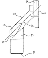
オーバーフロー装置Aは、オーバーフロー孔1に曲管または曲折管のオーバーフローエルボ2がパッキン3を介して接続し、且つ該オーバーフローエルボがオーバーフロー排水管Bに接続されるものである。そして、オーバーフロー孔1からオーバーフローエルボ2の流出口21までをほぼ同じ通水断面積にするとともに、該流出口21をオーバーフロー孔1より低位置に形成する。(図1) In the overflow device A, a bent pipe or an overflow elbow 2 of a bent pipe is connected to the overflow hole 1 via a
そこで、オーバーフロー装置は、オーバーフローエルボ2がオーバーフロー孔1に接続する俯角の曲管または曲折管でなっている。
俯角は、30度から60度の角度であって、望ましくは45度である。(図2)Therefore, the overflow device is a depression or bent tube in which the overflow elbow 2 is connected to the overflow hole 1.
The depression angle is an angle of 30 to 60 degrees, and preferably 45 degrees. (Figure 2)
このオーバーフロー装置は、オーバーフロー水が溢れ始めは、オーバーフロー孔1及びオーバーフローエルボ2の内壁に伝え沿ってオーバーフロー排水管Bへ流れているが、増水すると、オーバーフローエルボ2が曲管または曲折管であるので、特に、オーバーフローエルボ2がオーバーフロー孔1に俯角で接続しているので、オーバーフロー水が、直ぐにオーバーフロー孔1及びオーバーフローエルボ2の流入口26付近を塞ぐように満され、これより先の流出口21までの孔内を負圧とし、この負圧が塞いでいるオーバーフロー水を吸引し、吸引によって流出口21への流れの勢いを増すことになって流出し続ける。 In this overflow device, when overflow water begins to overflow, it flows to the overflow drain pipe B along the inner walls of the overflow hole 1 and the overflow elbow 2, but when the water increases, the overflow elbow 2 is a bent pipe or a bent pipe. In particular, since the overflow elbow 2 is connected to the overflow hole 1 at a depression angle, the overflow water is immediately filled so as to close the vicinity of the
そして、オーバーフロー装置Aは、オーバーフロー孔1からオーバーフローエルボ2の流出口21までがほぼ同じ通水断面積にするとともに、該流出口21をオーバーフロー孔1より低位置に形成することによって、孔内に空気溜りを生ずることなく、流出口21より流出するオーバーフロー水の重量によってオーバーフロー水の吸引となり、この吸引が流れの増速となって、サイフォン現象を起し、流れの増速が、結果的には、オーバーフロー水の増量した排水をすることができる。
よって、このようなオーバーフロー装置を備えていれば、仮に、オーバーフロー孔が小さいものであっても、流れを遅帯させたり、閉塞させたりすることは通常ではない。The overflow device A has substantially the same water flow cross-sectional area from the overflow hole 1 to the
Therefore, if such an overflow device is provided, even if the overflow hole is small, it is not normal to delay or block the flow.
なお、オーバーフローエルボ2をオーバーフロー孔1に俯角に接続することは、オーバーフロー水の流れを円滑にし、且つサイフォン現象を起こし易くすることにあるが、オーバーフローエルボ2をオーバーフロー孔1に取付けるとき、オーバーフローエルボ2を握ってもそれが邪魔にならずに螺子締めをすることができるといった施工上の利点もある。 Note that connecting the overflow elbow 2 to the overflow hole 1 at a depression angle facilitates the flow of overflow water and facilitates siphoning. However, when the overflow elbow 2 is attached to the overflow hole 1, the overflow elbow 2 There is also a construction advantage that even if 2 is gripped, it can be screwed without disturbing it.
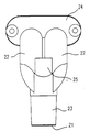
図2、図3は、設計上、加工上、並びに意匠上より、オーバーフロー孔を小さくしたが、オーバーフロー水の流量を減少させないように、2個のオーバーフロー孔1を並設したオーバーフロー装置のオーバーフローエルボ2を示す。 FIGS. 2 and 3 show an overflow elbow of an overflow device in which two overflow holes 1 are arranged in parallel so that the overflow hole is made smaller from the viewpoint of design, processing and design, but the flow rate of overflow water is not reduced. 2 is shown.
洗面台などでは、オーバーフロー水の溢れ出しを防止するため、ボールに大きなオーバーフロー孔を形成すればよいことになるが、意匠上、見栄えよくない。また、ボールに水を溜めるに当って、その満水時のボールへの容量を増すには、設計上、小さなオーバーフロー孔にすることで、満水時のボールの水の深さが増すことができる。また、オーバーフロー孔が小さいと、小さな孔の加工をすればよいことですみ、況して丸孔であると加工上の仕易さが上げられる。 In a washstand or the like, a large overflow hole may be formed in the ball in order to prevent overflow of overflow water, but it does not look good in terms of design. Further, in order to increase the capacity of the ball when the ball is full when the water is stored in the ball, the water depth of the ball when it is full can be increased by designing a small overflow hole. In addition, if the overflow hole is small, it is only necessary to process a small hole, and if it is a round hole, the workability is improved.
しかしながら、サイフォン現象を起すオーバーフロー装置であっても、そのオーバーフロー孔を極度に小さくすると、通水断面積が小さくなり、流量の限度を生ずることになる。
そこで、2個のオーバーフロー孔によるオーバーフロー装置について説明する。However, even in an overflow device that causes a siphon phenomenon, if the overflow hole is made extremely small, the cross-sectional area of water flow becomes small and a limit of the flow rate is generated.
Therefore, an overflow device having two overflow holes will be described.
2個のオーバーフロー孔に接続するオーバーフローエルボ2は、2個のオーバーフロー孔のそれぞれに接続する俯角の細管22と、この細管の流れを合流させた基管23と、それぞれの細管をオーバーフロー孔にパッキン3を介してともに接続させるフランジ24とからなっている。 The overflow elbow 2 connected to the two overflow holes includes a
2個のオーバーフロー孔に接続するオーバーフローエルボ2の細管22の各々の流れを合流させる交叉部25、及び流れを合流させた基管23の流出口21がオーバーフロー孔より低位置にされ、オーバーフロー孔から流出口21までを通水断面積がほぼ同じにされる。
即ち、2個のオーバーフロー孔の通水断面積、オーバーフローエルボ2の2本の細管22の通水断面積、そして基管23の通水断面積がともに、ほぼ同じである。The
That is, the cross-sectional area of the two overflow holes, the cross-sectional area of the two
オーバーフローエルボ2は、オーバーフロー孔より流入されたオーバーフロー水の流れが、オーバーフローエルボ2の細管22で曲折し、細管の交叉部25である流れの合流部分で再び曲折する曲折管になっている。 The overflow elbow 2 is a bent tube in which the flow of overflow water flowing in from the overflow hole is bent by the
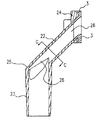
細管22の各々が流れを合流させる交叉部25には、細管22、基管23の流れに沿っての断面図である図4に示すように、整流壁28が設けられ、流れに渦流を起したり、空気溜りを生じさせたりしないようになっていて流暢に流れる。 As shown in FIG. 4, which is a cross-sectional view along the flow of the
この2個のオーバーフロー孔に接続されるオーバーフローエルボ2でなるオーバーフロー装置は、オーバーフロー水の溢れ始めには、どちらか一方のオーバーフロー孔からそれに繋っている細管22を経て、それらの内壁に伝い沿って流出口21より流出し、オーバーフロー排水管Bへ排出される。 In the overflow device composed of the overflow elbow 2 connected to these two overflow holes, the overflow water begins to overflow from one of the overflow holes to the inner wall via the
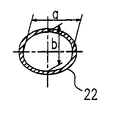
オーバーフロー水が増量すると、オーバーフローエルボ2は、渦流による空気溜りを生じないような曲折管、即ち、オーバーフロー孔に接続する俯角の細管22で、しかも該細管が、図5で示すように、通水断面を横径aより縦径bの短い楕円形状になっているので、この細管22のため、先ずこの細管の流入口26付近がオーバーフロー水で満され、塞がれ、それより先の基管23の流出口21までの孔内が負圧となって、オーバーフロー水を吸引し、後には、オーバーフローエルボ2がほぼ同じ通水断面積をしているので、空気溜りを生ずることなく、オーバーフロー水をオーバーフロー孔1から吸引される。 When the amount of overflow water increases, the overflow elbow 2 is a bent tube that does not cause air accumulation due to eddy current, that is, a
そして、オーバーフローエルボ2は、細管の交叉部25の流れの合流部分、及び流出口21がオーバーフロー孔より低位置にあるので、この曲折管内にあるオーバーフロー水の重量でサイフォン現象を起し、流れをスムーズに増量して、排水される。
よって、オーバーフロー水の流れの遅延や閉塞を起すことがない。And since the overflow elbow 2 has the confluence portion of the flow of the crossing
Therefore, there is no delay or blockage of the overflow water flow.
なお、オーバーフロー水で細管22が塞がるように満たされるには、2個の細管22の片方づつから始められるので、況してこの細管22が細いので、サイフォン現象を速く発生させ、且つ吸引が強いので流速を速め、孔内の汚れを付きづらくし、それとともに流量を増すことになる。 In order to fill the
ところで、本発明で多く用いられる実施態様としてのオーバーフローエルボは、オーバーフロー孔に俯角45度で接続する2個の細管22が、その各々の口径17mmで、長さ58mmであり、これらの流れを合流させる交叉部25を設けるとともに、この細管に45度で曲折する基管23が、口径21mmで、長さ53mmである。 By the way, the overflow elbow as an embodiment often used in the present invention has two
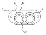
図6、図7は、オーバーフローエルボ2をオーバーフロー孔に接続するに当って、介入されるパッキン3である。
このパッキン3は、オーバーフローエルボ2の孔端に入れ子状に装着する挿入部部分31と、オーバーフローエルボ2のフランジ24に位置決めで嵌合するリブ32とを備えており、該リブ32は、オーバーフローエルボ2のフランジ24の上端と下端とに形成された溝へ嵌合してパッキン3をフランジへ確実に位置決め固定できることになる。6 and 7 show the
The
よって、パッキン3が、オーバーフローエルボ2の孔端に入れ子状に挿入部31を装着させているので、パッキン3の孔はオーバーフローエルボ2孔内と面一となって、空気溜りの起因が解消されることになる。 Therefore, since the
図8、図9は、オーバーフロー孔1とオーバーフローエルボ2との間に介在されるパッキン3aの他の実施例を示すものであって、該パッキン3aは、そのオーバーフロー水の流れる孔の孔面外側1個所に膨出部33を形成し、この膨出部33によって、オーバーフロー水が表面張力で引張られてオーバーフロー孔内周に沿い流れ、空気溜りを起すことになく、瞬時にオーバーフロー孔水が満し、速くサイフォン現象を起すことになる。
よって、このようなパッキンを採用することによって、速く流量を増し、且つ効率的にオーバーフロー水の排水をさせることになる。
なお、図中、34はシール性を向上させるためのビードである。8 and 9 show another embodiment of the
Therefore, by adopting such a packing, the flow rate is increased quickly and the overflow water is efficiently drained.
In the figure, 34 is a bead for improving the sealing performance.
A オーバーフロー装置
B オーバーフロー排水管
1 オーバーフロー孔
2 オーバーフローエルボ
21 流出口
22 細管
23 基管
24 フランジ
25 交叉部
26 流入口
28 整流壁
3 パッキン
31 挿入部
32 リブ
33 膨出部
34 ビードA Overflow device B Overflow drain pipe 1 Overflow hole 2
Claims (8)
Priority Applications (1)
| Application Number | Priority Date | Filing Date | Title |
|---|---|---|---|
| JP2006053760A JP2007205147A (en) | 2006-02-02 | 2006-02-02 | Overflow device |
Applications Claiming Priority (1)
| Application Number | Priority Date | Filing Date | Title |
|---|---|---|---|
| JP2006053760A JP2007205147A (en) | 2006-02-02 | 2006-02-02 | Overflow device |
Publications (1)
| Publication Number | Publication Date |
|---|---|
| JP2007205147A true JP2007205147A (en) | 2007-08-16 |
Family
ID=38484840
Family Applications (1)
| Application Number | Title | Priority Date | Filing Date |
|---|---|---|---|
| JP2006053760A Pending JP2007205147A (en) | 2006-02-02 | 2006-02-02 | Overflow device |
Country Status (1)
| Country | Link |
|---|---|
| JP (1) | JP2007205147A (en) |
Cited By (4)
| Publication number | Priority date | Publication date | Assignee | Title |
|---|---|---|---|---|
| JP2013002144A (en) * | 2011-06-16 | 2013-01-07 | Sekisui Chem Co Ltd | Rain gutter system |
| JP2013231287A (en) * | 2012-04-27 | 2013-11-14 | Maruichi Corp | Drain trap |
| JP2016176330A (en) * | 2016-06-08 | 2016-10-06 | 積水化学工業株式会社 | Gutter system |
| KR20220145571A (en) * | 2021-04-22 | 2022-10-31 | 주식회사 알앤더블유 | The showcase type towermodular hydroponics apparatus |
Citations (5)
| Publication number | Priority date | Publication date | Assignee | Title |
|---|---|---|---|---|
| JPS4857331A (en) * | 1971-11-06 | 1973-08-11 | ||
| JPH08260551A (en) * | 1995-03-27 | 1996-10-08 | Inax Corp | Drainage socket for connecting toilet bowl to soil-pipe |
| JPH0978651A (en) * | 1995-09-09 | 1997-03-25 | Toto Ltd | Overflow preventive device for bathtub |
| JP2004156288A (en) * | 2002-11-06 | 2004-06-03 | Tanico Corp | Overflow structure for sinks, etc. and detachable plate used for this |
| JP2005054468A (en) * | 2003-08-05 | 2005-03-03 | Sekisui Chem Co Ltd | Drainage header |
-
2006
- 2006-02-02 JP JP2006053760A patent/JP2007205147A/en active Pending
Patent Citations (5)
| Publication number | Priority date | Publication date | Assignee | Title |
|---|---|---|---|---|
| JPS4857331A (en) * | 1971-11-06 | 1973-08-11 | ||
| JPH08260551A (en) * | 1995-03-27 | 1996-10-08 | Inax Corp | Drainage socket for connecting toilet bowl to soil-pipe |
| JPH0978651A (en) * | 1995-09-09 | 1997-03-25 | Toto Ltd | Overflow preventive device for bathtub |
| JP2004156288A (en) * | 2002-11-06 | 2004-06-03 | Tanico Corp | Overflow structure for sinks, etc. and detachable plate used for this |
| JP2005054468A (en) * | 2003-08-05 | 2005-03-03 | Sekisui Chem Co Ltd | Drainage header |
Cited By (5)
| Publication number | Priority date | Publication date | Assignee | Title |
|---|---|---|---|---|
| JP2013002144A (en) * | 2011-06-16 | 2013-01-07 | Sekisui Chem Co Ltd | Rain gutter system |
| JP2013231287A (en) * | 2012-04-27 | 2013-11-14 | Maruichi Corp | Drain trap |
| JP2016176330A (en) * | 2016-06-08 | 2016-10-06 | 積水化学工業株式会社 | Gutter system |
| KR20220145571A (en) * | 2021-04-22 | 2022-10-31 | 주식회사 알앤더블유 | The showcase type towermodular hydroponics apparatus |
| KR102615723B1 (en) * | 2021-04-22 | 2023-12-20 | 주식회사 알앤더블유 | The showcase type towermodular hydroponics apparatus |
Similar Documents
| Publication | Publication Date | Title |
|---|---|---|
| JP6078713B2 (en) | Check valve | |
| JP2010180997A (en) | Drain pipe line structure | |
| JP4617415B2 (en) | Drain trap | |
| JP4968495B2 (en) | Drainage pipe | |
| JP4399522B2 (en) | Overflow device | |
| JP5624337B2 (en) | Drainage coupler | |
| JP6944745B2 (en) | Drain trap | |
| JP4779073B2 (en) | Drainage equipment | |
| JP6454848B2 (en) | Drain pipe | |
| JP7429635B2 (en) | siphon drainage system | |
| JP6019287B2 (en) | Drain trap | |
| JP3593620B2 (en) | Drain socket for connecting toilet bowl and defecation pipe | |
| JP4797205B2 (en) | Drain trap | |
| JP4114204B2 (en) | Drain socket | |
| JP2010236203A (en) | Flush toilet bowl | |
| JP4114203B2 (en) | Drain socket | |
| JP6303087B2 (en) | Overflow device | |
| JP6820173B2 (en) | Drain trap | |
| JP7249495B2 (en) | Drain joint with perforated plate | |
| JP2020029710A (en) | Drainage structure | |
| JP2011032797A (en) | Drain trap | |
| JP6508612B2 (en) | Flush toilet bowl | |
| JP6659207B2 (en) | Flush toilet | |
| JP2007002495A (en) | Double-basin sink | |
| EP3346065A1 (en) | Flush toilet |
Legal Events
| Date | Code | Title | Description |
|---|---|---|---|
| A621 | Written request for application examination |
Free format text: JAPANESE INTERMEDIATE CODE: A621 Effective date: 20090128 |
|
| A977 | Report on retrieval |
Free format text: JAPANESE INTERMEDIATE CODE: A971007 Effective date: 20110422 |
|
| A131 | Notification of reasons for refusal |
Free format text: JAPANESE INTERMEDIATE CODE: A131 Effective date: 20110719 |
|
| A02 | Decision of refusal |
Free format text: JAPANESE INTERMEDIATE CODE: A02 Effective date: 20111122 |