JP2019144360A - Performance support system and control method - Google Patents
Performance support system and control method Download PDFInfo
- Publication number
- JP2019144360A JP2019144360A JP2018027425A JP2018027425A JP2019144360A JP 2019144360 A JP2019144360 A JP 2019144360A JP 2018027425 A JP2018027425 A JP 2018027425A JP 2018027425 A JP2018027425 A JP 2018027425A JP 2019144360 A JP2019144360 A JP 2019144360A
- Authority
- JP
- Japan
- Prior art keywords
- unit
- performer
- music
- reproduction
- support system
- Prior art date
- Legal status (The legal status is an assumption and is not a legal conclusion. Google has not performed a legal analysis and makes no representation as to the accuracy of the status listed.)
- Granted
Links
Images


Landscapes
- Auxiliary Devices For Music (AREA)
- Electrophonic Musical Instruments (AREA)
Abstract
Description
本発明は、演奏支援システムおよび制御方法に関する。 The present invention relates to a performance support system and a control method.
例えば、楽器の演奏の練習や、コンサート等においては、MIDI規格(Musical Instrument Digital Interface)(登録商標)等の楽曲データをスピーカー等で再生して、その再生した楽曲に合わせて演奏者が楽器を演奏するという試みが行われている。 For example, when practicing playing musical instruments or performing concerts, music data such as MIDI standard (Musical Instrument Digital Interface) (registered trademark) is played back with a speaker, etc., and the performer plays a musical instrument along with the played music. Attempts have been made to perform.
上記楽曲データは、予め作成しておくこともでき、その際、抑揚、起伏、強弱、緩急等をつけて表現豊かな楽曲データを作成したとしても、実際に再生されるときは、作成した通りにしか再生されない。このため、演奏者は、再生された楽曲に合わせるだけという事態になりかねない。その結果、機械的な演奏になってしまい、いわゆる人間味が失われる。 The above music data can be created in advance. At that time, even if you create expressive music data with inflection, undulations, strengths, slowness, etc. Can only be played. For this reason, the performer may be in a situation where only the music is played. As a result, it becomes a mechanical performance, so-called humanity is lost.
楽曲データを再生しながら、その楽曲のテンポ、強弱をアレンジするための手段として、特許文献1に記載されているような装置が知られている。この装置によれば、指揮棒のような装置を用いて再生中の楽曲のテンポ、強弱を自由に変更することができる。 As a means for arranging the tempo and strength of the music while reproducing the music data, an apparatus as described in Patent Document 1 is known. According to this device, it is possible to freely change the tempo and strength of the music being played using a device such as a baton.
しかしながら、特許文献1に記載されているような装置を用いて再生中の楽曲をアレンジしながら、自身は、楽器の演奏を行うのは、到底無理である。 However, it is impossible to play a musical instrument while arranging the music being played using the apparatus described in Patent Document 1.
このように、楽曲データが再生された楽曲に合わせて演奏者が楽器の演奏を行う際に、表現豊かな楽曲を得るのは困難である。 In this way, it is difficult to obtain expressive music when a performer plays a musical instrument in accordance with music from which music data has been reproduced.
本発明の目的は、楽曲データが再生された楽曲に合わせて演奏者が楽器の演奏を行う際に、表現豊かな楽曲を得ることができる演奏支援システムおよび制御方法を提供することにある。 An object of the present invention is to provide a performance support system and a control method capable of obtaining a musical composition rich in expression when a performer plays a musical instrument in accordance with a musical composition from which musical composition data has been reproduced.
このような目的は、下記(1)〜(10)の本発明により達成される。
(1) 楽曲データを楽曲として再生する再生部と、
前記再生部によって再生された楽曲に合わせて楽器を演奏する演奏者に装着され、前記演奏者の動作を検出する動作検出部と、
前記動作検出部が検出した前記演奏者の動作に関する動作情報を受信する受信部と、
前記受信部が受信した前記動作情報に基づいて、前記再生部の再生条件を補正する制御部と、を備えることを特徴とする演奏支援システム。
Such an object is achieved by the present inventions (1) to (10) below.
(1) a playback unit that plays back music data as music;
An operation detection unit that is attached to a performer playing a musical instrument in accordance with the music reproduced by the reproduction unit, and detects an operation of the performer;
A receiver for receiving motion information relating to the performer's motion detected by the motion detector;
A performance support system comprising: a control unit that corrects a reproduction condition of the reproduction unit based on the operation information received by the reception unit.
(2) 前記制御部は、前記楽曲データのうちの、未だ再生されていない未再生データを補正して、前記再生部に再生させる上記(1)に記載の演奏支援システム。 (2) The performance support system according to (1), wherein the control unit corrects unreproduced data that has not been reproduced in the music data and causes the reproduction unit to reproduce the data.
(3) 前記制御部は、前記動作情報から前記演奏者が演奏しているテンポを検出し、その検出結果に基づいて、前記再生部による再生のテンポを補正する上記(2)に記載の演奏支援システム。 (3) The performance according to (2), wherein the control unit detects a tempo at which the performer is performing from the motion information, and corrects a tempo of reproduction by the reproduction unit based on the detection result. Support system.
(4) 前記動作検出部は、前記演奏者が演奏している間は、連続して前記動作情報を検出するものであり、
前記制御部は、所定時間での前記演奏者が演奏しているテンポの平均値を算出する上記(2)または(3)に記載の演奏支援システム。
(4) The motion detection unit continuously detects the motion information while the performer is playing,
The performance support system according to (2) or (3), wherein the control unit calculates an average value of tempos performed by the performer at a predetermined time.
(5) 前記制御部は、前記平均値が所定の範囲内であった場合、前記未再生データのテンポを補正せず、前記平均値が所定の範囲外であった場合、前記未再生データのテンポを補正する上記(4)に記載の演奏支援システム。 (5) When the average value is within a predetermined range, the control unit does not correct the tempo of the unreproduced data, and when the average value is outside the predetermined range, The performance support system according to (4), wherein the tempo is corrected.
(6) 前記制御部は、所定時間毎に前記平均値を算出し、最新の前記平均値を、前記未再生データのテンポを補正するか否かの判断に用いる上記(5)に記載の演奏支援システム。 (6) The performance according to (5), wherein the control unit calculates the average value every predetermined time and uses the latest average value for determining whether to correct the tempo of the unreproduced data. Support system.
(7) 前記制御部は、前記動作情報から前記演奏者の演奏の強弱を検出し、その検出結果に基づいて、前記未再生データの強弱を補正して、前記再生部に再生させる上記(2)ないし(6)のいずれかに記載の演奏支援システム。 (7) The control unit detects the strength of the performance of the performer from the motion information, corrects the strength of the unreproduced data based on the detection result, and causes the playback unit to reproduce (2) ) To (6).
(8) 前記動作検出部は、角速度センサーを有する上記(1)ないし(7)のいずれかに記載の演奏支援システム。 (8) The performance support system according to any one of (1) to (7), wherein the motion detection unit includes an angular velocity sensor.
(9) 前記再生部は、前記楽器を演奏する演奏装置を有する上記(1)ないし(8)のいずれかに記載の演奏支援システム。 (9) The performance support system according to any one of (1) to (8), wherein the reproduction unit includes a performance device for performing the musical instrument.
(10) 楽曲データを楽曲として再生する再生部と、前記再生部によって再生された楽曲に合わせて楽器を演奏する演奏者に装着され、前記演奏者の動作を検出する動作検出部と、前記動作検出部が検出した前記演奏者の動作に関する動作情報を受信する受信部と、を備える演奏支援システムを制御する制御方法であって、
前記受信部が受信した前記動作情報に基づいて、前記再生部の再生条件を補正することを特徴とする制御方法。
(10) A playback unit that plays back music data as a song, an operation detection unit that is attached to a player who plays a musical instrument in accordance with the music played back by the playback unit, and that detects the player's operation, and the operation A control method for controlling a performance support system comprising: a reception unit that receives operation information related to the player's motion detected by the detection unit;
A control method, comprising: correcting a reproduction condition of the reproduction unit based on the operation information received by the reception unit.
本発明によれば、楽曲データが再生された楽曲に合わせて演奏者が楽器の演奏を行う際に、表現豊かな楽曲を得ることができる演奏支援システムおよび制御方法を提供することができる。 ADVANTAGE OF THE INVENTION According to this invention, when a performer plays a musical instrument according to the music by which music data were reproduced | regenerated, the performance assistance system and control method which can obtain a music rich in expression can be provided.
以下、本発明の演奏支援システムおよび制御方法を添付図面に示す好適な実施形態に基づいて詳細に説明する。 Hereinafter, the performance support system and control method of the present invention will be described in detail based on preferred embodiments shown in the accompanying drawings.
図1は、本発明の演奏支援システムの概略構成図である。図2は、図1に示す演奏支援システムのブロック図である。図3は、図1に示す演奏装置の一例を示す側面図である。図4は、図1に示す動作検出部を演奏者に装着した状態を示す図である。図5は、図1に示す動作検出部を演奏者に装着した状態で演奏者が楽器を演奏している状態を示す図である。図6は、図1に示す制御装置が行う制御動作(本発明の制御方法)を説明するためのフローチャートである。図7は、縦軸が、動作検出部が検出した角速度、横軸が時間で表されるグラフである。図8および図9は、縦軸がBPM、横軸が時間で表されるグラフである。図10〜図13は、再生部が再生する楽曲のBPMを示す曲線である。 FIG. 1 is a schematic configuration diagram of a performance support system according to the present invention. FIG. 2 is a block diagram of the performance support system shown in FIG. FIG. 3 is a side view showing an example of the performance apparatus shown in FIG. FIG. 4 is a diagram illustrating a state in which the motion detection unit illustrated in FIG. 1 is attached to the performer. FIG. 5 is a diagram illustrating a state in which the performer is playing a musical instrument with the motion detection unit illustrated in FIG. 1 attached to the performer. FIG. 6 is a flowchart for explaining a control operation (control method of the present invention) performed by the control device shown in FIG. FIG. 7 is a graph in which the vertical axis represents the angular velocity detected by the motion detection unit, and the horizontal axis represents time. 8 and 9 are graphs in which the vertical axis represents BPM and the horizontal axis represents time. 10 to 13 are curves showing the BPM of the music reproduced by the reproducing unit.
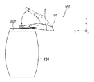
図1に示す演奏支援システム1は、再生される楽曲とともに演奏者100が楽器200を演奏する際に、演奏者100の演奏を支援するシステムである。この演奏支援システム1は、再生部2と、演奏者100に装着される動作検出部3と、演奏者が行う演奏のテンポを表示する表示装置4と、これら各部の制御を行う制御装置5と、を備えている。
The performance support system 1 shown in FIG. 1 is a system that supports the performance of the
以下、演奏支援システム1の各部について詳細に説明する。
[再生部]
図1に示す再生部2は、後述する制御装置5のメモリー53(図2参照)に記憶されている楽曲データを楽曲として再生(出力)する機能を有する。
Hereinafter, each part of the performance support system 1 will be described in detail.
[Playback section]
The reproducing
再生部2は、スピーカー21と、楽器300を演奏する演奏装置22と、を備えている。
The
スピーカー21は、制御装置5と電気的に接続されており、制御装置5から送信された楽曲データの電気信号を物理信号に変換して音を発して楽曲を再生するものである。スピーカー21が再生する楽曲データとしては、後に詳述するが、各種オーディオデータや、MIDIデータ(MIDI規格(Musical Instrument Digital Interface)(登録商標)の楽曲データ)等が挙げられる。
The
このスピーカー21と制御装置5との通信は、無線、有線の何れであってもよい。また、スピーカー21には、音量を調節する調節部が設けられていてもよい。
Communication between the
また、図示の構成では、再生部2が有するスピーカー21は1つであるが、これに限定されず、再生部2が有するスピーカー21は複数であってもよい。
In the illustrated configuration, the
図3に示す演奏装置22は、楽器300を演奏する演奏装置である。
楽器300としては、特に限定されず、例えば、後述するような、打楽器、弦楽器、鍵盤楽器、管楽器等が挙げられるが、本実施形態では、一例として、打楽器であるドラム301(スネアドラム、バスドラム、ハイハット、ライドシンバル、クラッシュシンバル)として説明する。
The
The
なお、本明細書中では、楽器とは、自身が音を発するものや、自身が発した音を増幅させてスピーカー等から出力するものや、自身は音を出さないが電気信号が入力されることによってスピーカー等から出力するものを含む。 In this specification, a musical instrument means a sound that it produces itself, a sound that it amplifies and outputs from a speaker, etc., or an electric signal that does not produce sound but is input Output from a speaker or the like.
演奏装置22は、ドラム301の各部(スネアドラム、バスドラム、ハイハット、ライドシンバル、クラッシュシンバル)にそれぞれ設けられた打撃部221と、打撃部221を駆動する駆動部222とを有している。
The
各打撃部221および各駆動部222は、設置位置および姿勢が異なること以外は略同様の構成であるため、以下では、スネアドラム(以下、スネアドラム302と言う)に設置された打撃部221および駆動部222について代表的に説明する。
Since each
打撃部221は、スティック221aと、スティック221aの基端部(グリップ)を回動可能に支持する回動支持部221bと、スティック221aの長手方向の途中に連結されたバネ221cと、ストッパー221dとを有する。
The
スティック221aは、スネアヘッドと衝突することによって音を鳴らすことができるものであれば特に限定されず、例えば、木製、金属製、樹脂製のものや、いわゆるブラシスティック等が挙げられる。また、ドラム301の部位(スネアドラム、バスドラム、ハイハット、ライドシンバル、クラッシュシンバル)に応じて先端部(チップ)に例えばスポンジ体等を装着してもよい。
The
回動支持部221bは、スティック221aを回動軸221e回りに回動可能に支持する。この回動支持部221bは、ヘッド303(打撃面)よりも上方(離間する側)に設置されている。また、回動軸221eは、スネアドラム302のヘッド303と略平行となっている。
The
この回動支持部221bによって、スティック221aは、スネアドラム302のヘッド303と当接(打撃)する状態と、離間した状態とをとり得る。なお、スネアドラム302のヘッド303と当接(打撃)する状態では、スティック221aの先端部(チップ)がヘッド303と当接するとともに、スティック221aの長手方向の途中(ショルダー)がリム304と当接するのが好ましい。これにより、鮮明な打撃音を得ることができる。
By this
バネ221cは、スティック221aの長手方向の途中に連結され、スティック221aがスネアドラム302から離間する方向に付勢するものである。これにより、スティック221aに外力が付与していない自然状態では、スティック221aは、スネアドラム302から離間した状態となる。
The
ストッパー221dは、スティック221aの移動限界を規制するものである。これにより、スティック221aの位置が不本意にずれたりするのを防止することができ、安定した打撃音を得ることができる。
The
駆動部222は、ロッド222aを有するソレノイドで構成されている。ロッド222aは、通電により駆動する駆動源(図示せず)によって、出没自在に構成されており、スティック221aのグリップを打撃する状態と、スティック221aから離間した状態とをとり得る。
The
ロッド222aがスティック221aを打撃(押圧)することよって、図3中二点鎖線で示すように、スティック221aがバネ221cの付勢力に抗して回動し、スティック221aの先端部(チップ)がヘッド303を打撃するとともにスティック221aの長手方向の途中(ショルダー)がリム304と当接する。これにより、スネアドラム302から打撃音を生じさせることができる。
When the
一方、ロッド222aが退避してスティック221aから離間した状態では、スティック221aは、バネ221cの付勢力によってスネアドラム302から離間した状態となる。
On the other hand, when the
ロッド222aが上記出没を繰り返すことによって、スネアドラム302を演奏することができる。
The
このような駆動部222は、制御装置5と電気的に接続されており、その作動が制御される。なお、駆動部222と制御装置5との通信は、無線、有線の何れであってもよい。
Such a
以上、再生部2について説明した。特に、再生部2が、楽器300を演奏する演奏装置22を有することにより、例えば、スピーカー等では再現できない楽器の倍音等の臨場感を演出することができる。
The
なお、本実施形態では、再生部2は、スピーカー21と演奏装置22とを有する構成である場合について説明したが、これらのうちのいずれか一方のみを有する構成であってもよい。
In the present embodiment, the case where the
また、再生部2は、例えば、イヤホンやヘッドホン等、演奏者100が装着する機器であってもよい。これにより、例えば、演奏者100が自宅で楽器200を練習する際、音量を気にせず、再生部2との合奏を楽しむことができる。なお、この構成の場合、イヤホンやヘッドホンが接続されるジャックは、制御装置5が収納された筐体(図示せず)や、スピーカー21に設けられた構成とすることができる。
Further, the
また、以下では、スピーカー21が再生する楽曲と、演奏装置22が演奏する楽曲とを合わせて、単に「再生部2による楽曲」とも言う。
Hereinafter, the music played by the
[動作検出部]
図4および図5に示す動作検出部3は、楽器200を演奏する演奏者100の動作を検出する機能を有する。
[Motion detector]
The
楽器200としては、特に限定されず、例えば、打楽器、弦楽器、鍵盤楽器、管楽器等が挙げられるが、本実施形態では、一例として、打楽器であるコンガ201として説明する。
The
なお、上記打楽器としては、上記ドラム、電子ドラム、和太鼓、カホン、ジャンベ、タンバリン、トライアングル、カスタネット、ウッドブロック、カウベル、拍子木、クラベス、木魚、ボンゴ、ティンパニ、コンサートチャイム、ウインドチャイム、カバサ、スレイベル、ティンパレス、アゴゴ等が挙げられる。 The percussion instrument includes the drum, electronic drum, Japanese drum, cajon, djembe, tambourine, triangle, castanets, wood blocks, cowbells, beat trees, claves, wooden fish, bongo, timpani, concert chimes, wind chimes, cabbages, Examples include slaves, tin palaces, and agogo.
上記弦楽器としては、アコースティックギター、エレキギター、アコースティックベース、エレキベース、ハープ、マンドリン、ヴァイオリン、ヴィオラ、チェロ、コントラバス等が挙げられる。 Examples of the stringed instrument include acoustic guitar, electric guitar, acoustic bass, electric bass, harp, mandolin, violin, viola, cello, and contrabass.
上記鍵盤楽器としては、ピアノ、ホンキートンクピアノ、エレクトリックピアノ、キーボード、チェンバロ、チェレスタ、オルガン、パイプオルガン、リードオルガン、エレクトーン、鍵盤ハーモニカ、アコーディオン、シンセサイザー等が挙げられる。 Examples of the keyboard instrument include a piano, a honky tonk piano, an electric piano, a keyboard, a harpsichord, a Celesta, an organ, a pipe organ, a reed organ, an electric tone, a keyboard harmonica, an accordion, and a synthesizer.
上記管楽器としては、フルート、クラリネット、オーボエ、サクスフォーン、ファゴット、笙、バグパイプ等の木管楽器や、トランペット、トンロンボーン、ホルン、ユーフォニアム、チューバ、ホイッスル、サンバホイッスル等の金管楽器等が挙げられる。 Examples of the wind instruments include woodwind instruments such as flute, clarinet, oboe, saxophone, bassoon, bass and bagpipe, and brass instruments such as trumpet, tonronborn, horn, euphonium, tuba, whistle and samba whistle.
これらの楽器の中でも、例えば、打楽器等、演奏の動作が大きいものや、演奏時に楽器に対する接触(インパクト)の瞬間の反力が大きいものが好ましい。これにより、動作検出部3による動作を明確に検出することができ、演奏者100の動作をより顕著に検出することができる。
Among these instruments, for example, instruments having a large performance such as percussion instruments and instruments having a large reaction force at the moment of contact (impact) with the instrument during performance are preferable. Thereby, the operation | movement by the operation |
動作検出部3は、本実施形態では、角速度を検出する角速度センサー31で構成されている。角速度センサー31は、筐体311と、筐体311に内蔵されたセンサー素子312と、制御装置5と通信を行う通信部313とを有する(図2参照)。
In the present embodiment, the
筐体311は、演奏者100の手首101にリストバンド102によって装着されている。なお、図示の構成に限定されず、指、頭部、腹部、足等、任意の部位に装着してもよい。また、動作検出部3は、演奏者100の任意の部位に複数装着されていてもよい。
The
センサー素子312は、静電容量式、歪みゲージ式、圧電式、渦電流式、電磁誘導式、光式のいずれのタイプのものであってもよい。センサー素子312が検出した角速度の情報は、電気信号に変換されて通信部313によって制御装置5に送信される。通信部313と制御装置5との通信は、無線、有線の何れであってもよい。
The sensor element 312 may be of any type of capacitance type, strain gauge type, piezoelectric type, eddy current type, electromagnetic induction type, and optical type. Information on the angular velocity detected by the sensor element 312 is converted into an electrical signal and transmitted to the control device 5 by the
ここで、図4および図5には、互いに交わる(直交する)x軸、y軸、z軸を図示している。x軸は、水平方向に沿った軸であり、かつ、演奏者100の左右方向に沿った軸である。y軸は、水平方向に沿った軸であり、かつ、前後方向に沿った軸である。z軸は、鉛直方向に沿った軸である。
Here, FIGS. 4 and 5 show x-axis, y-axis, and z-axis that intersect (orthogonal) each other. The x-axis is an axis along the horizontal direction and an axis along the left-right direction of the
図5に示すように、演奏者100がコンガ201を演奏する際、すなわち、コンガ201のヘッド202を叩く際、手を回動させる運動を行う。この運動の際、手および動作検出部3は、x軸回りに回動する。このため、演奏者100が演奏を行っているとき、x軸回りの角速度が顕著に変化する(図7参照)。よって、演奏者100の動作をより確実に検出することができる。
As shown in FIG. 5, when the
なお、演奏者100の動作をより顕著に検出するための軸は、楽器の種類に応じて、異なっている。例えば、ギターを演奏する場合には、演奏者100のピックを把持する方の手は、y軸回りに回転する。このため、y軸回りの角速度の変化が顕著になる。
In addition, the axis | shaft for detecting the operation | movement of the
また、楽器の種類に応じて角速度センサーに代えて、加速度センサーを用いてもよい。例えば、演奏者100がヴァイオリンを演奏する場合、弓を把持する方の手は、略x軸方向に沿って往復運動を行う。このため、この場合は、加速度センサーを用いた場合、x軸方向の加速度の変化が顕著になり、演奏者100の動作をより確実に検出することができる。
Further, an acceleration sensor may be used instead of the angular velocity sensor according to the type of musical instrument. For example, when the
このように、本実施形態では、演奏者100がコンガ201を演奏するため、角速度センサーが内蔵されているが、これに限定されず、楽器の種類に応じて、加速度センサー、角加速度センサー、磁気センサー、感圧センサー、変位センサー等を用いてもよい。また、これら各センサーのうちの複数が筐体311に内蔵されたものを用いてもよい。
As described above, in this embodiment, the
また、本実施形態では、演奏者100が演奏を行っている間は、動作検出部3は、連続して作動している。
Moreover, in this embodiment, while the
[表示装置]
図1に示す表示装置4は、表示画面41と、操作ボタン42と、通信部43とを有している。
[Display device]
The display device 4 illustrated in FIG. 1 includes a
表示画面41は、例えば、液晶画面、有機EL画面等で構成される。この表示画面41には、動作検出部3が検出した演奏者100の演奏のテンポが表示される。本実施形態では、BPM(Beats Per Minute)が表示される。この数値は、1分間に四分音符が何回現れるかを示す値であり、例えば、120BPMの場合、表示画面41には、「120」という数値が表示される。このBPMの算出方法は、後に詳述する。
The
また、表示画面41には、リアルタイム(例えば、1小節ごと)で演奏のBPMが表示される。従って、120BPMで演奏していて、演奏がもたついた場合、例えば、「110」という数字に切り替わる。
The
このような表示装置4によれば、演奏者100が、自身が演奏しているテンポの絶対的数値を知ることができる。さらに、相対的に早くなったか遅くなったかも把握することができ、表示画面41を見て修正することができる。
According to such a display device 4, the
また、操作ボタン42は、演奏者100が押圧操作すると、その情報を通信部43が電気信号に変換して制御装置5に送信する。これにより、後述するように制御装置5が再生部2を駆動して、再生部2が楽曲を再生する。よって、演奏者100が、再生部2が再生した楽曲に合わせて演奏を開始することができる。
When the
なお、操作ボタン42は、メカニカルスイッチや、表示画面41上に設けられた、いわゆるタッチパネル式であってもよい。
The
また、表示装置4は、例えば、ギターやベース等のチューニングを行う機能を有していてもよい。また、メトロノーム機能を有していてもよい。これにより、演奏者100は、表示装置4を参照しつつ、任意のテンポで演奏を行うことができる。メトロノーム機能としては、音を発するもの以外に、光、指示棒の動きなどでテンポを参照できるものであってもよい。
Further, the display device 4 may have a function of tuning a guitar or a bass, for example. Further, it may have a metronome function. Thus, the
また、表示画面41には、BPMの大小を示すインジケーターが表示されていてもよい。このインジケーターには、BPMの基準値が表示され、この基準値に対してゲージが増減する構成であるのが好ましい。これにより、演奏者100のBPMが速いか遅いかが一目で分かる。また、正確な演奏を可能とするため、基準値となるBPMに対して、演奏者100のBPMが、高い頻度、低い頻度、同じ頻度等を、回数や百分率などで表示するよう構成してもよく、標準偏差を表示するよう構成してもよい。
The
[制御装置]
図2に示すように、制御装置5は、CPU(Central Processing Unit)51と、I/Oインターフェース(受信部)52と、メモリー(記憶部)53とを有している。
[Control device]
As shown in FIG. 2, the control device 5 includes a CPU (Central Processing Unit) 51, an I / O interface (reception unit) 52, and a memory (storage unit) 53.
CPU(制御部)51は、メモリー53に記憶された複数のモジュールや、各種プログラム等を実行する。複数のモジュールは、論理ゲート、半導体デバイス、集積回路または他のどのような個別部品を含むハードウエア回路における内蔵コンポーネントを含んでいてもよい。また、モジュールは、ソフトウェアプログラムの一部であってもよい。ソフトウェアプログラムとしてのモジュールの実行は、CPU51または他のどのようなハードウェアエンティティによって実行されるべき論理演算命令のセットを含んでいてもよい。また、モジュールは、インターフェースを用いて、命令やプログラムのセットで具現化されていてもよい。
A CPU (control unit) 51 executes a plurality of modules stored in the
I/Oインターフェース52は、他の通信機器(再生部2、動作検出部3、表示装置4等)と通信を行うためのものである。I/Oインターフェース52としては、特に限定されないが、音声、アナログ、デジタル、モノラル、RCA、ステレオ、IEEE−1394、シリアルバス、ユニバーサルシリアルバス(USB)、赤外線、PS/2、BNC、同軸、コンポーネント、コンポジット、DVI(Digital Visual Interface)、HDMI(High-Definition Multimedia Interface)(登録商標)、RFアンテナ、S−ビデオ、VGA、ブルートゥース(登録商標)、Cellular(例えば、CDMA(Code-Division Multiple Access)、HSPA+(High-Speed Packet Access)、GSM(Global System for Mobile communications)(登録商標)、LTE(Long-Term Evolution)、WiMax等)、Wi-Fi規格、無線LAN等の通信プロトコル/方法を採用してもよい。
The I /
このI/Oインターフェース52は、動作検出部3が検出した演奏者100の動作に関する動作情報を受信する受信部として機能する。
The I /
メモリー53は、例えば不揮発性半導体メモリーの一種であるEEPROM(Electrically Erasable Programmable Read-Only Memory)等で構成されている。メモリー53に記憶されたモジュールは、再生モジュール531と、平均BPM算出モジュール532と、補正モジュール533と、通信モジュール534と、を含む。
The
再生モジュール531は、CPU51によって実行されたとき、楽曲データを再生部2によって再生するよう構成されている。
The
平均BPM算出モジュール532は、CPU51によって実行されたとき、後述する平均BPMを算出するよう構成されている。
The average
補正モジュール533は、CPU51によって実行されたとき、後述するように、再生部2によって再生される楽曲を補正するよう構成されている。
The
通信モジュール534は、CPU51によって実行されたとき、他の通信機器(再生部2、動作検出部3、表示装置4等)と通信を行うよう構成されている。
The
また、メモリー53には、再生部2が楽曲を再生するための楽曲データが記憶されている。この楽曲データは、特に限定されないが、例えば、WAVE(RIFF waveform Audio Format)、mp3(MPEG Audio Layer-3)等の音声ファイルフォーマットからなるオーディオデータや、MIDIデータ(MIDI規格(Musical Instrument Digital Interface)(登録商標)の楽曲データ)等が挙げられるが、以下では、MIDIデータとして説明する。MIDIデータを用いることにより、後述するような制御を容易に行うことができる。
The
また、メモリー53には、上記の他に、後述するような制御プログラム(本発明の制御方法)等が記憶されている。このような制御装置5は、表示装置4に内蔵されていてもよく、表示装置4とは異なる筐体に内蔵されたものであってもよい。
In addition to the above, the
以上、制御装置5について説明した。このような制御装置5は、以下で説明するような制御を行うことにより、再生部2の楽曲に合わせて演奏者100が楽器を演奏するのを支援することができる。以下、制御装置5の制御動作(本発明の制御方法)について、図6に示すフローチャートを用いて説明するが、演奏者100が再生部2の楽曲を再生する以前の段階から説明する。
The control device 5 has been described above. Such a control device 5 can assist the
まず、演奏者100がコンガ201を試演し、その平均BPMを算出する(ステップS101:平均BPM算出ステップ)。この算出方法を、図8に示すグラフを用いて説明する。
First, the
図8(図9についても同様)に示すグラフは、縦軸がBPMであり、横軸が時間(sec)となっている。このグラフには、演奏者100の動作が閾値を超えたとき、すなわち、コンガ201を打撃する際に、閾値を超える程度の強い打撃を検出したときを抽出し、各打撃を四分音符のタイミングとみなし、ある打撃とその次の打撃とを比較してBPMとしてプロットしている。
In the graph shown in FIG. 8 (the same applies to FIG. 9), the vertical axis represents BPM and the horizontal axis represents time (sec). In this graph, when the performance of the
また、時間t(所定時間)ごとに、その間の複数回(本実施形態では、3回)の打撃のBPMの平均値を相加平均で算出し、その値を平均BPMとする。なお、平均の算出方法としては、相乗平均、調和平均、加重平均などを用いてもよい。 In addition, for each time t (predetermined time), an average value of BPMs of a plurality of hits (three times in the present embodiment) in the meantime is calculated as an arithmetic average, and the value is set as an average BPM. Note that a geometric average, a harmonic average, a weighted average, or the like may be used as an average calculation method.
なお、本ステップでは、リアルタイムでBPMを表示装置4に表示する。これにより、演奏者100が試奏しているときのBPMをリアルタイムで把握することができる。よって、再生部2で再生したいBPMに近づけることができる。また、練習時に用いたとき、テンポキープが出来ているかを演奏者100が知ることができ、演奏の熟練度の向上に寄与する。
In this step, the BPM is displayed on the display device 4 in real time. Thereby, BPM when the
また、演奏者100のBPMに対して所定の範囲を設定し、所定の範囲から外れたら、その打撃を平均値の算出に用いないよう構成してもよい。例えば、BPMが100付近で演奏していて、演奏ミスでBPMが150になっても、この150という値は、平均値の算出に用いない。これにより、平均BPMの算出をより正確に、すなわち、演奏者100の意図に沿って行うことができる。
Further, a predetermined range may be set for the BPM of the
なお、上記では、各打撃を四分音符のタイミングとみなして平均BPMを算出したが、これに限定されず、例えば、八分音符のタイミングとみなして算出した値を2で割って平均BPMを算出してもよい。 In the above description, the average BPM is calculated by regarding each hit as a quarter note timing. However, the present invention is not limited to this. For example, the average BPM is calculated by dividing a value calculated by regarding the timing of an eighth note by two. It may be calculated.
また、上記では、各BMPに対して統計処理を行うことによって平均BPMを決定してもよい。例えば、分散や標準偏差を求め、頻度が多いBPMを平均BPMとしてもよい。 In the above, the average BPM may be determined by performing statistical processing on each BMP. For example, the variance or standard deviation is obtained, and the BPM having a high frequency may be used as the average BPM.
そして、ステップS102(再生BPM決定ステップ)において、再生部2が再生する楽曲のBPM(再生BPM)を決定する。
In step S102 (playback BPM determination step), the BPM (playback BPM) of the music played back by the
本実施形態では、演奏者100が、動作検出部3が装着された方の手首をひねる。すなわち、演奏者100が手首をy軸回りに回転させる。動作検出部3からの信号のうち、y軸回りの角速度が所定の値を超えた場合、その時点における平均BPMを再生BPMとして決定する。すなわち、ステップS101で算出した時間tごとの平均BPMのうち、最新の値を再生BPMとする。
In the present embodiment, the
なお、演奏者100が再生BPMを決定する際のトリガーとしては、演奏時の動作と区別することができれば、特に限定されない。
The trigger when the
なお、例えば、表示装置4からボタンなどで操作を行って再生BPMを決定する指示を行うよう構成してもよい。 Note that, for example, an instruction to determine the playback BPM may be performed by operating the display device 4 with a button or the like.
次いで、ステップS103(再生指示判断ステップ)において、演奏者100から再生指示があったか否かを判断する。再生指示があった場合、所定時間後に再生部2を駆動して再生を開始する。
Next, in step S103 (reproduction instruction determination step), it is determined whether or not there is a reproduction instruction from the
本ステップでは、ステップS102にてトリガーとして用いた動作や演奏時の動作とは異なる動作を再生指示の有無の判断に用いるのが好ましく、例えば、水平方向(x軸方向またはy軸方向)の加速度が閾値を超えた場合、再生指示があったとみなす。これにより、再生BPMの決定の指示と明確に区別することができ、再生指示の有無の判断を正確に行うことができる。 In this step, it is preferable to use an operation different from the operation used as a trigger in step S102 or the operation at the time of performance for determining whether or not there is a reproduction instruction. For example, acceleration in the horizontal direction (x-axis direction or y-axis direction) is used. If the value exceeds the threshold, it is considered that a reproduction instruction has been issued. Thereby, it can be clearly distinguished from the instruction for determining the reproduction BPM, and the presence / absence of the reproduction instruction can be accurately determined.
なお、例えば、表示装置4からボタンなどで操作を行って再生BPMを決定する指示を行うよう構成してもよい。また、例えば、タイマーを用いて、所定時間以上演奏の動きを検出しなかったら、準備完了とみなして、最後(最新)の平均BPMを再生BPMとしてもよい。また、ステップS102とステップS103との順番を入れ替えてもよい。 Note that, for example, an instruction to determine the playback BPM may be performed by operating the display device 4 with a button or the like. Further, for example, when a performance of a performance is not detected for a predetermined time or more using a timer, it is considered that preparation is completed, and the last (latest) average BPM may be used as the reproduction BPM. Further, the order of step S102 and step S103 may be switched.
ステップS103において再生指示があったと判断した場合、所定時間後に再生部2を駆動させて再生部2による楽曲の再生を開始する(ステップS104:再生部駆動ステップ)。
If it is determined in step S103 that a playback instruction has been given, the
本実施形態では、前述したように、メモリー53に記憶されている楽曲データは、MIDI規格のデータであるため、簡単な制御でスピーカー21および演奏装置22の同期をとることができる。
そして、再生部2の楽曲に合わせて、演奏者100がコンガ201を演奏する。
In the present embodiment, as described above, since the music data stored in the
Then, the
次いで、ステップS105において、演奏者100の演奏の強度が所定の範囲内であるか否かを判断する(ステップS105:強度判断ステップ)。なお、所定の範囲とは、予めメモリー53に記憶された(設定された)値であり、動作検出部3が検出する角速度の値(動作情報)において、最大値Smaxと最小値Sminとの間の領域である(図7参照)。すなわち、動作検出部3が検出した角速度の大小を、演奏者100の演奏の強弱とみなす。
なお、これら最大値Smaxおよび最小値Sminは、適宜変更することができる。
Next, in step S105, it is determined whether or not the performance intensity of the
Note that the maximum value S max and the minimum value S min can be changed as appropriate.
ステップS105において、動作検出部3が検出する角速度の値が最大値Smaxを超えたと判断した場合、再生部2が再生する楽曲データのうちの、未だ再生されていない(これから再生するデータ)未再生データの強度を強くするよう補正して再生する。すなわち、再生部2による再生音量が大きくなるよう楽曲データを補正する。
In step S105, when it is determined that the value of the angular velocity detected by the
一方、動作検出部3が検出する角速度の値が最小値Sminを下回ったと判断した場合、再生部2が再生する楽曲データのうちの、未だ再生されていない(これから再生するデータ)未再生データの強度を弱くするよう補正して再生する。すなわち、再生部2による再生音量が小さくなるよう楽曲データを補正する。
On the other hand, when it is determined that the value of the angular velocity detected by the
上記補正は、例えば、検出した角速度の情報を演奏の強弱となるベロシティー値に対応させて、MIDIデータのベロシティー信号に変換することにより行うことができる。なお、MIDIのエクスプレッション値やボリューム値等に対応させてもよい。 The correction can be performed, for example, by converting the detected angular velocity information into a velocity signal of MIDI data in association with a velocity value that is a strength of performance. It is also possible to correspond to a MIDI expression value, volume value, or the like.
このように、制御装置5は、演奏者100の動作情報から演奏者100の演奏の強弱を検出し、その検出結果に基づいて、未再生データの強弱を補正して、再生部2に再生させる(ステップS106:強弱補正ステップ)。これにより、演奏者100の演奏の強弱を再生部2の楽曲に反映することができる。よって、よって、演奏者100が再生部2の楽曲に合わせて演奏する、すなわち、合奏する場合であっても、演奏者100が表現したい音楽性が損なわれず、表現豊かな楽曲を得ることができる。
In this way, the control device 5 detects the strength of the performance of the
なお、再生部2の楽曲の強弱を補正する際、どの程度音量を補正するかは、例えば、検出した加速度の大小と、再生部2の再生音量を示す検量線(図示せず)に基づいて行うことができる。
In addition, when correcting the strength of the music of the
また、再生部2が楽曲を再生している間、演奏者100の動作を検出し、演奏者100の演奏の平均BPMが所定の範囲内か否かを判断する(ステップS107:平均BPM判断ステップ)。なお、所定の範囲とは、予めメモリー53に記憶された(設定された)最大値BPMmaxと最小値BPMminとの間の領域であり、最大値BPMmaxおよび最小値BPMminは、適宜変更することができる。
Further, while the
演奏者100の演奏の平均BPMが上記範囲外であった場合、再生部2が再生する楽曲データのうちの、未だ再生されていない(これから再生するデータ)未再生データのテンポを補正して再生する(ステップS108:テンポ補正ステップ)。これにより、演奏者100のテンポの変化を反映させた楽曲を再生部2から再生することができる。
When the average BPM of the performance of the
なお、再生部2のテンポの補正は、演奏者100のBPMと同じ値に随時追従させてもよいが、演奏者100のBPMが徐々に変化していった場合、その変化をある程度予測して、再生部2のテンポの補正を案内する構成とすることができる。
The tempo correction of the
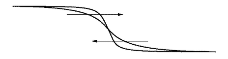
演奏者100のBPMの変化を予測する際、例えば、演奏者100のBPMのプロットを、各種関数を用いて直線または曲線に近似して、演奏者100のBPMのプロットを予測することができる。この関数としては、n次関数(nは、自然数)やこれらの多項式や、これらを変形させた関数が挙げられるが、シグモイド関数を用いるのが特に好ましい。これにより、自然な予測および追従を実現することができる。
このシグモイド関数としては、例えば、下記式(1)で示すようなものが挙げられる。
When predicting the change in the BPM of the
As this sigmoid function, for example, one represented by the following formula (1) can be cited.

この式(1)を用いたグラフを図9に示す。図9に示すグラフでは、演奏者100のBPMをドットで示し、再生部2のBPMを実線で示している。シグモイド関数を用いることにより、再生部2のBPMを示す実線は、なだらかなS字曲線を描く。このため、この曲線に沿って再生部2の楽曲のテンポを補正することにより、前述したような自然な予測および追従を実現することができる。
A graph using this equation (1) is shown in FIG. In the graph shown in FIG. 9, the BPM of the
また、式(1)中a1〜a7は、適宜値を設定することができ、各値を変更することにより、再生部2のBPMを示す実線を以下のように変更することができる。
Also, equation (1) was a 1 ~a 7 can be set as appropriate values by changing the values, it is possible to change the solid line indicating the BPM of the
図10に示すように、a1の値を大きくすると、グラフ中曲線部分以降の位置を下側にシフトさせることができる。a1の値を小さくすると、グラフ中曲線部分以降の位置を上側にシフトさせることができる。 As shown in FIG. 10, increasing the value of a 1, a position in the curved section after the graph can be shifted to the lower side. Lower values of a 1, it is possible to shift the position in the curved section after the graph on the upper side.
また、図10に示すように、a2の値を大きくすると、グラフ中曲線部分以降の位置を上側にシフトさせることができる。a2の値を小さくすると、グラフ中曲線部分以降の位置を下側にシフトさせることができる。 Further, as shown in FIG. 10, increasing the value of a 2, it is possible to shift the position in the curved section after the graph on the upper side. Lower values of a 2, a position in the curved section after the graph can be shifted to the lower side.
また、図11に示すように、a3の値を大きくすると、グラフ中曲線部分を右側にシフトさせることができ、a3の値を小さくすると、グラフ中曲線部分を左側にシフトさせることができる。 Further, as shown in FIG. 11, increasing the value of a 3, it is possible to shift the curved portion in the graph to the right, reducing the value of a 3, it is possible to shift the curved portion in the graph on the left .
また、図12に示すように、a4の値を大きくすると、グラフ中曲線部分の開始位置を右側にシフトさせることができるとともに、グラフ中曲線部分の終了位置を左側にシフトさせることができる。a4の値を小さくすると、グラフ中曲線部分の開始位置を左側にシフトさせることができるとともに、グラフ中曲線部分の終了位置を右側にシフトさせることができる Further, as shown in FIG. 12, increasing the value of a 4, it is possible with the start position of the curved portion in the graph can be shifted to the right, shifting the end point of the curved section in the graph on the left. Lower values of a 4, it is possible to it is possible to shift the starting position of the curved portion in the graph to the left, shifting the end point of the curved section in the graph on the right
また、図11に示すように、a5の値を大きくすると、グラフ中曲線部分を右側にシフトさせることができ、a5の値を小さくすると、グラフ中曲線部分を左側にシフトさせることができる。 Further, as shown in FIG. 11, increasing the value of a 5, it is possible to shift the curved portion in the graph to the right, reducing the value of a 5, it is possible to shift the curved portion in the graph on the left .
また、図11に示すように、a6の値を大きくすると、グラフ中曲線部分を右側にシフトさせることができ、a6の値を小さくすると、グラフ中曲線部分を左側にシフトさせることができる。 Further, as shown in FIG. 11, increasing the value of a 6, it is possible to shift the curved portion in the graph to the right, reducing the value of a 6, it is possible to shift the curved portion in the graph on the left .
また、図13に示すように、a7の値を大きくすると、グラフ全体を上側にシフトさせることができ、a7の値を小さくすると、グラフ全体を下側にシフトさせることができる。 As shown in FIG. 13, when the value of a 7 is increased, the entire graph can be shifted upward, and when the value of a 7 is decreased, the entire graph can be shifted downward.
このような式(関数)は、予めメモリー53に記憶されている。なお、演奏者100の平均BPMが徐々に速くなる(アッチェレランド)場合は、上記式(1)の右辺に−1を乗算した式を用いて制御を行うことができる。
Such an expression (function) is stored in the
このような補正案内では、演奏者100がBPMを変化させて演奏することにより、多段階で追加補正を行うこともできる。例えば、リタルダンドの場合、だんだん遅くなるようにBPMを補正案内させたつもりが、BPMの減少をもっと下げたいと判断した時点で、BPMを下げた演奏を行うと、それがトリガーとなって、再補正が行われて、再度、補正案内が行われる。
In such correction guidance, the
具体的に説明すると、例えば、式(1)を用いて補正を行っている途中で、式(1)中a1〜a7を変更する補正を行うことにより、案内終了時のBPMや、それに至るタイミングや、BPMの変化度合いを変更することもできる。また、例えば、一次関数を用いて案内をしていたときに、途中で傾きを変更したりすることもできる。 More specifically, for example, by performing correction by changing a 1 to a 7 in the equation (1) during the correction using the equation (1), the BPM at the end of the guidance, It is also possible to change the timing to reach and the degree of change in BPM. Further, for example, when guidance is performed using a linear function, the inclination can be changed in the middle.
このように補正データを算出してその信号を再生部2に送信する。また、楽曲データがMIDI規格のデータであるため、MIDIクロック信号を補正して再生部2に送信するという簡単な制御で上記補正を行うことができる。
In this way, correction data is calculated and the signal is transmitted to the reproducing
演奏者100の演奏の平均BPMが上記範囲内であった場合、未再生データのテンポを補正せず、後述するステップS111に移行する。
If the average BPM of the performance of the
このように、制御装置5は、平均BPM(平均値)が所定の範囲内であった場合、未再生データのテンポを補正せず、平均BPM(平均値)が所定の範囲外であった場合、未再生データのテンポを補正する。これにより、演奏者100の演奏のテンポのわずかなズレに、再生部2の楽曲が随時追従してしまい、演奏自体が不自然になってしまうのを防止することができる。よって、自然な演奏(合奏)を提供することができる。
As described above, when the average BPM (average value) is within the predetermined range, the control device 5 does not correct the tempo of the unreproduced data, and the average BPM (average value) is outside the predetermined range. Correct the tempo of unplayed data. As a result, it is possible to prevent the musical piece of the
また、制御装置5は、所定時間毎(図示の構成では、時間t毎)に前記平均値を算出し、最新の平均値を、未再生データのテンポを補正するか否かの判断に用いる。これにより、最新の演奏者の意図を、再生部2による楽曲に反映させることができる。
Further, the control device 5 calculates the average value every predetermined time (in the illustrated configuration, every time t), and uses the latest average value to determine whether or not to correct the tempo of unreproduced data. Thereby, the intention of the latest performer can be reflected in the music by the reproducing
最大値BPMmaxは、特に限定されないが、例えば、平均BPMの5%〜20%程度であるのが好ましく、平均BPMの8%〜11%程度であるのがより好ましい。最小値BPMminは、特に限定されないが、例えば、平均BPMの−20%〜−5%程度であるのが好ましく、平均BPMの−11%〜−8%程度であるのがより好ましい。これにより、上記効果をより確実に発揮することができる。 The maximum value BPM max is not particularly limited, but is preferably about 5% to 20% of the average BPM, and more preferably about 8% to 11% of the average BPM. The minimum value BPM min is not particularly limited. For example, the minimum value BPM min is preferably about −20% to −5% of the average BPM, and more preferably about −11% to −8% of the average BPM. Thereby, the said effect can be exhibited more reliably.
そして、ステップS109(補正解除指示判断ステップ)において、演奏者100からテンポの補正解除の指示があったか否かを判断する。
In step S109 (correction cancellation instruction determination step), it is determined whether or not the
本ステップでは、演奏者100が装着している動作検出部3からの信号によって判断する。ステップS102およびステップS103にてトリガーとして用いた動作や演奏時の動作とは異なる動作を補正解除指示の有無の判断に用いるのが好ましい。これにより、補正解除指示を、再生BPMの決定の指示および再生指示と明確に区別することができ、補正解除指示の有無の判断を正確に行うことができる。
In this step, the determination is made based on a signal from the
ステップS109において、補正解除指示があったと判断した場合、テンポの補正を解除、すなわち、元のBPM(テンポ補正前の最新の平均BPM)に戻して、再生部2から楽曲を再生する(ステップS110:補正解除ステップ)。 If it is determined in step S109 that a correction cancellation instruction has been issued, the tempo correction is canceled, that is, the original BPM (the latest average BPM before the tempo correction) is restored, and the music is played from the playback unit 2 (step S110). : Correction cancellation step).
なお、ステップS109において、補正解除指示が無いと判断した場合、ステップS111に移行する。 If it is determined in step S109 that there is no correction cancellation instruction, the process proceeds to step S111.
そして、再生終了指示があったか否かを判断する(ステップS111:再生終了指示判断ステップ)。 Then, it is determined whether or not there has been a reproduction end instruction (step S111: reproduction end instruction determination step).
本ステップでは、演奏者100が装着している動作検出部3からの信号によって判断する。ステップS102、ステップS103およびステップS109にてトリガーとして用いた動作や演奏時の動作とは異なる動作を再生終了指示の有無の判断に用いるのが好ましい。これにより、再生終了指示を、再生BPMの決定の指示、再生指示および補正解除指示と明確に区別することができ、再生終了指示の有無の判断を正確に行うことができる。
In this step, the determination is made based on a signal from the
ステップS111において、再生終了指示があった場合、再生部2による再生を終了する。また、ステップS111において、再生終了指示がないと判断した場合、ステップS105に戻り、以下のステップを順次繰り返す。
In step S111, when there is a reproduction end instruction, the reproduction by the
なお、上記ステップS104〜S111の途中に、楽曲データを最後まで再生した場合には、その時点で強制終了する。 If the music data is reproduced to the end during the steps S104 to S111, the process is forcibly terminated at that time.
以上説明したように、演奏支援システムは、楽曲データを楽曲として再生する再生部2と、再生部2によって再生された楽曲に合わせて楽器200を演奏する演奏者100に装着され、演奏者100の動作を検出する動作検出部3と、動作検出部3が検出した演奏者100の動作に関する動作情報を受信する受信部(I/Oインターフェース52)と、受信部(I/Oインターフェース52)が受信した動作情報に基づいて、再生部2の再生条件を補正するCPU51(制御部)と、を備える。
As described above, the performance support system is attached to the
このような本発明によれば、演奏者100の演奏中の動作情報を取得し、その動作情報を、リアルタイムで再生部2が再生する楽曲に反映することができる。よって、演奏者100が再生部2の楽曲に合わせて演奏する、すなわち、合奏する場合であっても、演奏者100が表現したい音楽性が損なわれず、表現豊かな楽曲を得ることができる。
According to the present invention as described above, it is possible to acquire motion information during the performance of the
また、本実施形態では、制御装置5は、演奏者100の動作情報から演奏者100が演奏しているテンポを検出し、その検出結果に基づいて、再生部2による再生のテンポを補正する。これにより、演奏者100が演奏中にテンポを変更したとしても、再生部2による楽曲もその変更したテンポで再生される。よって、さらに表現豊かな楽曲を得ることができる。
In the present embodiment, the control device 5 detects the tempo at which the
このため、例えば、バンドメンバーがそろっていなくても、ライブハウス等で表現豊かなバンド演奏を行うことができたり、オーケストラのメンバーがそろっていなくても、コンサート会場等で表現豊かなオーケストラ演奏を行うことができる。また、身体が不自由で楽器の演奏(合奏)をあきらめていた人も、合奏することの楽しさを体感することができる。 For this reason, for example, even if there are not all band members, you can perform expressive band performances at a live house, etc., or even if you do not have orchestral members, you can perform expressive orchestra performances at concert venues, etc. It can be carried out. In addition, people who are physically disabled and who have given up playing musical instruments (ensembles) can also experience the joy of performing ensembles.
また、本発明によれば、演奏者100が楽器200の練習しているとき、再生部2の楽曲についていけずに、遅れをとってしまっても、再生部2の楽曲が演奏者100の演奏に追従してテンポを遅くすることができる。これにより、演奏者100が練習中に演奏をあきらめるのを防止することができ、楽器200の練習を楽しく継続することができる。
Further, according to the present invention, when the
このため、例えば、音楽教室等で本システムを導入することにより、老若男女問わず生徒が楽しくレッスンを長続きすることができる。 For this reason, for example, by introducing this system in a music classroom or the like, a student can enjoy a lesson for a long time regardless of age or gender.
以上、本発明の演奏支援システムおよび制御方法を図示の実施形態について説明したが、本発明は、これに限定されるものではなく、演奏支援システムおよび制御方法を構成する各部(ステップ)は、同様の機能を発揮し得る任意の構成のものと置換することができる。また、任意の構成物やステップが付加されていてもよい。 The performance support system and the control method of the present invention have been described above with respect to the illustrated embodiment. However, the present invention is not limited to this, and the components (steps) constituting the performance support system and the control method are the same. It can be replaced with any structure that can exhibit the above function. Arbitrary components and steps may be added.
また、前記実施形態では、制御部は、演奏者の動作情報に基づいて、再生部の再生条件を補正するに際し、楽曲データを補正してその補正データを再生する構成について説明したが、本発明ではこれに限定されず、例えば、楽曲データを補正せず、再生速度や、再生音量を補正する構成であってもよい。 Further, in the above-described embodiment, the configuration has been described in which the control unit corrects the music data and reproduces the correction data when correcting the playback condition of the playback unit based on the performance information of the performer. However, the present invention is not limited to this, and for example, a configuration in which the playback speed and playback volume are corrected without correcting the music data may be used.
また、制御部は、演奏者の動作情報に基づいて、再生部の再生条件を補正するに際し、楽曲データのうちの、未だ再生されていない未再生データを補正して、前記再生部に再生させる構成について説明したが、本発明ではこれに限定されず、例えば、楽曲データのうちの、既に再生された部分に対しても同様の補正を行ってもよい。この場合、演奏者の動作情報が楽曲データに反映され、次回以降再生する場合、演奏者の動作情報や、演奏意図等が組み込まれた楽曲データとなる。すなわち、楽曲データを編集する作業を容易に行うことができたり、この楽曲データを、演奏者自身が聞き返すことにより、演奏の熟練度の向上に寄与することができる。 Further, the control unit corrects unreproduced data that has not yet been reproduced among the music data when the reproduction condition of the reproduction unit is corrected based on the performance information of the performer, and causes the reproduction unit to reproduce it. Although the configuration has been described, the present invention is not limited to this. For example, the same correction may be performed on a portion of music data that has already been reproduced. In this case, the player's motion information is reflected in the music data, and when it is reproduced from the next time, the player's motion information, performance intention, etc. are incorporated. That is, the work of editing music data can be easily performed, and the music player can listen to the music data and contribute to the improvement of the skill level of performance.
また、前記実施形態において、ステップS102、ステップS103、ステップS109およびステップS111では、一例として、判断基準のトリガーとして動作検出部が検出した動作を用いる場合について説明したが、本発明ではこれに限定されず、例えば、表示装置の操作ボタンや、別途設けたフットスイッチ等による操作であってもよい。 Further, in the above-described embodiment, in the steps S102, S103, S109, and S111, as an example, the case where the operation detected by the operation detection unit is used as a determination criterion trigger has been described, but the present invention is not limited thereto. Instead, for example, an operation using an operation button of the display device or a foot switch provided separately may be used.
なお、ステップS101およびステップS102を省略して、過去のデータに基づいて再生部が再生するBPMを決定してもよい。 Note that step S101 and step S102 may be omitted, and the BPM to be played back by the playback unit may be determined based on past data.
また、前記実施形態では、楽曲データが記憶された記憶部(メモリー)は、制御装置に内蔵されたものであったが、本発明ではこれに限定されず、外部の機器(例えば、USBフラッシュメモリー)に記憶された構成であってもよい。この場合、外部の装置を制御装置に接続することにより、実施形態で述べたような制御を行うことができる。 In the embodiment, the storage unit (memory) in which the music data is stored is built in the control device. However, the present invention is not limited to this, and an external device (for example, a USB flash memory) is used. ) May be stored. In this case, the control described in the embodiment can be performed by connecting an external device to the control device.
1 演奏支援システム
2 再生部
21 スピーカー
22 演奏装置
221 打撃部
221a スティック
221b 回動支持部
221c バネ
221d ストッパー
221e 回動軸
222 駆動部
222a ロッド
3 動作検出部
4 表示装置
41 表示画面
42 操作ボタン
43 通信部
5 制御装置
31 角速度センサー
311 筐体
312 センサー素子
313 通信部
51 CPU
52 I/Oインターフェース
53 メモリー
531 再生モジュール
532 平均BPM算出モジュール
533 補正モジュール
100 演奏者
101 手首
102 リストバンド
200 楽器
201 コンガ
202 ヘッド
300 楽器
301 ドラム
302 スネアドラム
303 ヘッド
304 リム
BPMmax 最大値
BPMmin 最小値
Smax 最大値
Smin 最小値
DESCRIPTION OF SYMBOLS 1
52 I /
Claims (10)
前記再生部によって再生された楽曲に合わせて楽器を演奏する演奏者に装着され、前記演奏者の動作を検出する動作検出部と、
前記動作検出部が検出した前記演奏者の動作に関する動作情報を受信する受信部と、
前記受信部が受信した前記動作情報に基づいて、前記再生部の再生条件を補正する制御部と、を備えることを特徴とする演奏支援システム。 A playback unit for playing back music data as music;
An operation detection unit that is attached to a performer playing a musical instrument in accordance with the music reproduced by the reproduction unit, and detects an operation of the performer;
A receiver for receiving motion information relating to the performer's motion detected by the motion detector;
A performance support system comprising: a control unit that corrects a reproduction condition of the reproduction unit based on the operation information received by the reception unit.
前記制御部は、所定時間での前記演奏者が演奏しているテンポの平均値を算出する請求項2または3に記載の演奏支援システム。 The motion detection unit continuously detects the motion information while the performer is playing,
The performance support system according to claim 2 or 3, wherein the control unit calculates an average value of tempos performed by the performer at a predetermined time.
前記受信部が受信した前記動作情報に基づいて、前記再生部の再生条件を補正することを特徴とする制御方法。 A playback unit that plays back music data as a song, a motion detection unit that is attached to a player who plays a musical instrument in accordance with the music played back by the playback unit, and detects the player's motion, and the motion detection unit A control method for controlling a performance support system comprising: a receiving unit that receives operation information related to the detected player's operation;
A control method, comprising: correcting a reproduction condition of the reproduction unit based on the operation information received by the reception unit.
Priority Applications (1)
| Application Number | Priority Date | Filing Date | Title |
|---|---|---|---|
| JP2018027425A JP7106091B2 (en) | 2018-02-19 | 2018-02-19 | Performance support system and control method |
Applications Claiming Priority (1)
| Application Number | Priority Date | Filing Date | Title |
|---|---|---|---|
| JP2018027425A JP7106091B2 (en) | 2018-02-19 | 2018-02-19 | Performance support system and control method |
Publications (2)
| Publication Number | Publication Date |
|---|---|
| JP2019144360A true JP2019144360A (en) | 2019-08-29 |
| JP7106091B2 JP7106091B2 (en) | 2022-07-26 |
Family
ID=67772273
Family Applications (1)
| Application Number | Title | Priority Date | Filing Date |
|---|---|---|---|
| JP2018027425A Active JP7106091B2 (en) | 2018-02-19 | 2018-02-19 | Performance support system and control method |
Country Status (1)
| Country | Link |
|---|---|
| JP (1) | JP7106091B2 (en) |
Cited By (1)
| Publication number | Priority date | Publication date | Assignee | Title |
|---|---|---|---|---|
| JP7366282B2 (en) | 2020-02-20 | 2023-10-20 | アンテスコフォ | Improved synchronization of pre-recorded musical accompaniments when users play songs |
Citations (6)
| Publication number | Priority date | Publication date | Assignee | Title |
|---|---|---|---|---|
| JPH03288896A (en) * | 1990-04-06 | 1991-12-19 | Yamaha Corp | Belt controller |
| JPH0654388A (en) * | 1992-04-07 | 1994-02-25 | Yamaha Corp | Sound parameter controller |
| JPH08278786A (en) * | 1995-04-07 | 1996-10-22 | Matsushita Electric Ind Co Ltd | Holonic rhythm generator device |
| JP2001215963A (en) * | 2000-02-02 | 2001-08-10 | Global A Entertainment Inc | Music playing device, music playing game device, and recording medium |
| JP2005062697A (en) * | 2003-08-19 | 2005-03-10 | Kawai Musical Instr Mfg Co Ltd | Tempo display device |
| JP2016114717A (en) * | 2014-12-12 | 2016-06-23 | 国立大学法人福井大学 | Automatic playing device and automatic playing method of percussion instrument |
-
2018
- 2018-02-19 JP JP2018027425A patent/JP7106091B2/en active Active
Patent Citations (6)
| Publication number | Priority date | Publication date | Assignee | Title |
|---|---|---|---|---|
| JPH03288896A (en) * | 1990-04-06 | 1991-12-19 | Yamaha Corp | Belt controller |
| JPH0654388A (en) * | 1992-04-07 | 1994-02-25 | Yamaha Corp | Sound parameter controller |
| JPH08278786A (en) * | 1995-04-07 | 1996-10-22 | Matsushita Electric Ind Co Ltd | Holonic rhythm generator device |
| JP2001215963A (en) * | 2000-02-02 | 2001-08-10 | Global A Entertainment Inc | Music playing device, music playing game device, and recording medium |
| JP2005062697A (en) * | 2003-08-19 | 2005-03-10 | Kawai Musical Instr Mfg Co Ltd | Tempo display device |
| JP2016114717A (en) * | 2014-12-12 | 2016-06-23 | 国立大学法人福井大学 | Automatic playing device and automatic playing method of percussion instrument |
Cited By (1)
| Publication number | Priority date | Publication date | Assignee | Title |
|---|---|---|---|---|
| JP7366282B2 (en) | 2020-02-20 | 2023-10-20 | アンテスコフォ | Improved synchronization of pre-recorded musical accompaniments when users play songs |
Also Published As
| Publication number | Publication date |
|---|---|
| JP7106091B2 (en) | 2022-07-26 |
Similar Documents
| Publication | Publication Date | Title |
|---|---|---|
| US9460695B2 (en) | Synthesizer with bi-directional transmission | |
| JP5664581B2 (en) | Musical sound generating apparatus, musical sound generating method and program | |
| US10832645B2 (en) | Transducer apparatus for a labrosone and a labrosone having the transducer apparatus | |
| CN107424593B (en) | Digital musical instrument of touch-control type curved surface stereo loudspeaker array is moved to regional stroke | |
| RU2502119C1 (en) | Musical sound generation instrument and computer readable medium | |
| JP2012018334A (en) | Player device and electric musical instrument | |
| JP2012118299A (en) | Performance device and electronic musical instrument | |
| US20110290097A1 (en) | Performance apparatus and electronic musical instrument | |
| US20100307314A1 (en) | Stringed instrument with keyboard | |
| JP2003076365A (en) | Musical sound controller | |
| JP2006163435A (en) | Musical sound controller | |
| JP4802857B2 (en) | Musical sound synthesizer and program | |
| JP7106091B2 (en) | Performance support system and control method | |
| JP7140083B2 (en) | Electronic wind instrument, control method and program for electronic wind instrument | |
| JP5732982B2 (en) | Musical sound generation device and musical sound generation program | |
| JP3972619B2 (en) | Sound generator | |
| JP2008242285A (en) | Performance device and program for attaining its control method | |
| KR101746216B1 (en) | Air-drum performing apparatus using arduino, and control method for the same | |
| JP2007078724A (en) | Electronic musical instrument | |
| JP2014238550A (en) | Musical sound producing apparatus, musical sound producing method, and program | |
| JP6111526B2 (en) | Music generator | |
| JP4244338B2 (en) | SOUND OUTPUT CONTROL DEVICE, MUSIC REPRODUCTION DEVICE, SOUND OUTPUT CONTROL METHOD, PROGRAM THEREOF, AND RECORDING MEDIUM CONTAINING THE PROGRAM | |
| JP7440727B2 (en) | Rhythm comprehension support system | |
| JP5742592B2 (en) | Musical sound generation device, musical sound generation program, and electronic musical instrument | |
| JP6149890B2 (en) | Musical sound generation device and musical sound generation program |
Legal Events
| Date | Code | Title | Description |
|---|---|---|---|
| RD01 | Notification of change of attorney |
Free format text: JAPANESE INTERMEDIATE CODE: A7426 Effective date: 20180403 |
|
| A621 | Written request for application examination |
Free format text: JAPANESE INTERMEDIATE CODE: A621 Effective date: 20210118 |
|
| A977 | Report on retrieval |
Free format text: JAPANESE INTERMEDIATE CODE: A971007 Effective date: 20211126 |
|
| A131 | Notification of reasons for refusal |
Free format text: JAPANESE INTERMEDIATE CODE: A131 Effective date: 20211207 |
|
| A521 | Request for written amendment filed |
Free format text: JAPANESE INTERMEDIATE CODE: A523 Effective date: 20220203 |
|
| TRDD | Decision of grant or rejection written | ||
| A01 | Written decision to grant a patent or to grant a registration (utility model) |
Free format text: JAPANESE INTERMEDIATE CODE: A01 Effective date: 20220628 |
|
| A61 | First payment of annual fees (during grant procedure) |
Free format text: JAPANESE INTERMEDIATE CODE: A61 Effective date: 20220706 |
|
| R150 | Certificate of patent or registration of utility model |
Ref document number: 7106091 Country of ref document: JP Free format text: JAPANESE INTERMEDIATE CODE: R150 |