JP2019129601A - Rotor for rotary electric machine - Google Patents
Rotor for rotary electric machine Download PDFInfo
- Publication number
- JP2019129601A JP2019129601A JP2018009882A JP2018009882A JP2019129601A JP 2019129601 A JP2019129601 A JP 2019129601A JP 2018009882 A JP2018009882 A JP 2018009882A JP 2018009882 A JP2018009882 A JP 2018009882A JP 2019129601 A JP2019129601 A JP 2019129601A
- Authority
- JP
- Japan
- Prior art keywords
- fitting
- rotor
- rotor core
- hole
- shaft
- Prior art date
- Legal status (The legal status is an assumption and is not a legal conclusion. Google has not performed a legal analysis and makes no representation as to the accuracy of the status listed.)
- Granted
Links
- 230000002093 peripheral effect Effects 0.000 claims abstract description 19
- 238000004519 manufacturing process Methods 0.000 abstract description 6
- 230000004907 flux Effects 0.000 description 9
- 230000002265 prevention Effects 0.000 description 8
- 229910000831 Steel Inorganic materials 0.000 description 3
- 238000000034 method Methods 0.000 description 3
- 239000010959 steel Substances 0.000 description 3
- 238000010586 diagram Methods 0.000 description 2
- 239000000463 material Substances 0.000 description 2
- 230000013011 mating Effects 0.000 description 2
- 229910000976 Electrical steel Inorganic materials 0.000 description 1
- 230000006866 deterioration Effects 0.000 description 1
- 238000010030 laminating Methods 0.000 description 1
- 230000000149 penetrating effect Effects 0.000 description 1
- 230000001360 synchronised effect Effects 0.000 description 1
Images


Classifications
-
- Y—GENERAL TAGGING OF NEW TECHNOLOGICAL DEVELOPMENTS; GENERAL TAGGING OF CROSS-SECTIONAL TECHNOLOGIES SPANNING OVER SEVERAL SECTIONS OF THE IPC; TECHNICAL SUBJECTS COVERED BY FORMER USPC CROSS-REFERENCE ART COLLECTIONS [XRACs] AND DIGESTS
- Y02—TECHNOLOGIES OR APPLICATIONS FOR MITIGATION OR ADAPTATION AGAINST CLIMATE CHANGE
- Y02T—CLIMATE CHANGE MITIGATION TECHNOLOGIES RELATED TO TRANSPORTATION
- Y02T10/00—Road transport of goods or passengers
- Y02T10/60—Other road transportation technologies with climate change mitigation effect
- Y02T10/64—Electric machine technologies in electromobility
Abstract
Description
本明細書は、ロータコアと、当該ロータコア内に埋め込まれる磁石と、ロータコアの軸孔に挿通されて固定される回転軸と、を備えた回転電機のロータを開示する。 The present specification discloses a rotor of a rotating electrical machine including a rotor core, a magnet embedded in the rotor core, and a rotating shaft that is inserted into and fixed to a shaft hole of the rotor core.
回転電機のロータでは、永久磁石が埋め込まれたロータコアの中心に回転軸が挿通されて固定されている。回転軸は、ロータコアとともに回転するために、ロータコアに強固に固定されることが求められる。そのため、従来から、回転軸の固定について、種々の技術が提案されている。 In a rotor of a rotating electrical machine, a rotating shaft is inserted and fixed at the center of a rotor core in which permanent magnets are embedded. The rotation shaft is required to be firmly fixed to the rotor core in order to rotate together with the rotor core. Therefore, conventionally, various techniques have been proposed for fixing the rotating shaft.
例えば、特許文献1にはナットを用いて、回転軸をロータコアに締結する技術が開示されている。すなわち、特許文献1では、回転軸に、ロータコアの軸方向一端面を支える大径部と、ナットが螺合される雌ネジと、を形成している。そして、回転軸に、ロータコアとナットを挿し込んだ後、ナットを、締めて、ロータコアをナットと大径部とで挟み込む。これにより、ロータコアの軸方向端面と、回転軸の大径部およびナットと、の間には、摩擦力が発生する。この摩擦力により、ロータコアと回転軸との間で回転力が伝達される。 For example, Patent Document 1 discloses a technique of fastening a rotating shaft to a rotor core using a nut. That is, in patent document 1, the large diameter part which supports the axial direction one end surface of a rotor core, and the internal thread with which a nut is screwed are formed in the rotating shaft. And after inserting a rotor core and a nut in a rotating shaft, a nut is tightened and a rotor core is inserted | pinched between a nut and a large diameter part. Thus, a frictional force is generated between the axial end surface of the rotor core and the large diameter portion of the rotation shaft and the nut. By this frictional force, the rotational force is transmitted between the rotor core and the rotating shaft.
しかしながら、こうしたナットを用いた締結の場合、ナットを適切なトルクで締め付けるための専用の設備が必要であり、製造コストの増加を招いていた。また、ロータコアの軸方向端面に生じる摩擦力で回転力を伝達するためには、ナットの締め付けトルクを大きくする必要があり、ナットの大型化や、ロータコアへの負荷増加などの問題も招いていた。 However, in the case of fastening using such a nut, a dedicated facility for fastening the nut with an appropriate torque is required, resulting in an increase in manufacturing cost. Further, in order to transmit the rotational force by the frictional force generated on the axial end surface of the rotor core, it is necessary to increase the tightening torque of the nut, which causes problems such as an increase in the size of the nut and an increase in load on the rotor core. .
そこで、本明細書では、部品を小型化でき、また、製造コストを低減できる回転電機のロータを開示する。 Therefore, the present specification discloses a rotor of a rotating electrical machine that can reduce the size of components and reduce the manufacturing cost.
本明細書で開示する回転電機のロータは、回転電機のロータであって、中心に延びる軸孔と、複数の磁極用孔と、を有するロータコアと、前記磁極用孔に挿入された永久磁石と、前記軸孔に挿通されて、1以上の嵌合部を介して前記軸孔に固定された回転軸と、を備え、前記嵌合部では、前記回転軸の外周面および前記軸孔の内周面の一方に設けられるとともに径方向に陥没する嵌合溝と、前記回転軸の外周面および前記軸孔の内周面の他方に設けられるとともに径方向に突出した嵌合突起と、が互いに嵌り合っており、前記嵌合部は、周方向に近接する二つの磁極用孔間の微小間隙部であるブリッジ部と周方向に重複しない位置に配されている、ことを特徴とする。 A rotor of a rotating electrical machine disclosed in the present specification is a rotor of a rotating electrical machine, and includes a rotor core having a shaft hole extending in the center and a plurality of magnetic pole holes, and a permanent magnet inserted into the magnetic pole hole. A rotating shaft that is inserted through the shaft hole and is fixed to the shaft hole via one or more fitting portions, wherein the fitting portion includes an outer peripheral surface of the rotating shaft and an inner portion of the shaft hole. A fitting groove provided on one of the peripheral surfaces and recessed in the radial direction, and a fitting protrusion provided on the other of the outer peripheral surface of the rotating shaft and the inner peripheral surface of the shaft hole and protruding in the radial direction are mutually connected. The fitting portion is arranged at a position that does not overlap in the circumferential direction with a bridge portion that is a minute gap portion between two magnetic pole holes adjacent in the circumferential direction.
かかる構成とすることで、嵌合部を介してロータコアと回転軸との間で回転力を伝達できるため、ナットが不要となる。結果として、部品を小型化でき、また、製造コストを低減できる。また、嵌合部が、強度的に弱いブリッジ部と周方向に重複しない位置に配されているため、ロータコアの破損を効果的に防止できる。 With such a configuration, a rotational force can be transmitted between the rotor core and the rotation shaft via the fitting portion, so that a nut is not necessary. As a result, the parts can be reduced in size and the manufacturing cost can be reduced. Further, since the fitting portion is disposed at a position that does not overlap with the bridge portion that is weak in strength in the circumferential direction, the rotor core can be effectively prevented from being damaged.
前記嵌合部は、前記嵌合突起の周方向寸法が前記嵌合溝の周方向寸法より大きい周側嵌合部と、前記嵌合突起の径方向寸法が前記嵌合溝の径方向寸法より大きい径側嵌合部と、を有してもよい。 The fitting portion includes a circumferential fitting portion in which a circumferential dimension of the fitting protrusion is larger than a circumferential dimension of the fitting groove, and a radial dimension of the fitting protrusion is larger than a radial dimension of the fitting groove. You may have a large diameter side fitting part.
かかる構成とすることで、周側嵌合部で回転が伝達され、径側嵌合部で回転軸の芯出しができる。 With such a configuration, rotation is transmitted by the circumferential fitting portion, and the rotation shaft can be centered by the radial fitting portion.
この場合、前記周側嵌合部と、前記径側嵌合部と、は、周方向に交互に並んでいてもよい。 In this case, the circumferential side fitting portions and the radial side fitting portions may be alternately arranged in the circumferential direction.
かかる構成とすることで、周方向の応力と径方向の応力とが、周方向に交互に発生するため、ロータコアにかかる負荷を均等に分散できる。 With this configuration, the circumferential stress and the radial stress are alternately generated in the circumferential direction, so the load applied to the rotor core can be evenly dispersed.
また、前記回転軸の外周面は、前記嵌合突起および嵌合溝として機能する歯および歯溝が周方向に連続して並ぶインボリュートスプライン形状であり、前記軸孔の内周面には、前記嵌合溝および嵌合突起として機能する歯溝および歯が、前記ブリッジ部と周方向に重複しない範囲に位置するように、間欠的に並んでいてもよい。 The outer peripheral surface of the rotating shaft has an involute spline shape in which teeth and tooth grooves functioning as the fitting protrusion and the fitting groove are continuously arranged in the circumferential direction, and the inner peripheral surface of the shaft hole has the The tooth grooves and teeth functioning as the fitting grooves and the fitting protrusions may be intermittently arranged so as to be located in a range not overlapping with the bridge portion in the circumferential direction.
回転軸の全周に、嵌合突起および嵌合溝を設けることで、1種類の回転軸を、ブリッジ部の位置や個数が異なる複数種類のロータコアに適用することができる。 By providing a fitting protrusion and a fitting groove on the entire circumference of the rotation shaft, one type of rotation shaft can be applied to a plurality of types of rotor cores having different positions and numbers of bridge portions.
また、前記嵌合部は、磁極境界位置と周方向に重複する位置に配されていてもよい。 The fitting portion may be disposed at a position overlapping the magnetic pole boundary position in the circumferential direction.
通常、磁極境界位置には、ブリッジ部は無いため、かかる構成とすることで、嵌合部とブリッジ部との重複を確実に防止できる。 Usually, since there is no bridge portion at the magnetic pole boundary position, such a configuration can reliably prevent overlapping of the fitting portion and the bridge portion.
本明細書で開示するロータによれば、嵌合部を介してロータコアと回転軸との間で回転力を伝達できるため、ナットが不要となる。結果として、部品を小型化でき、また、製造コストを低減できる。また、嵌合部が、強度的に弱いブリッジ部と周方向に重複しない位置に配されているため、ロータコアの破損を効果的に防止できる。 According to the rotor disclosed in the present specification, the rotational force can be transmitted between the rotor core and the rotating shaft via the fitting portion, so that a nut is not necessary. As a result, the parts can be reduced in size and the manufacturing cost can be reduced. Further, since the fitting portion is disposed at a position that does not overlap with the bridge portion that is weak in strength in the circumferential direction, the rotor core can be effectively prevented from being damaged.
以下、回転電機のロータ10の構成について図面を参照して説明する。図1は、回転電機のロータ10の概略縦断面図である。また、図2は、図1におけるA−A断面図である。また、図3は、ロータコア12の軸孔26周辺の図であり、図4は、回転軸16の断面図である。このロータ10は、回転電機、例えば、駆動源の一つとして電動車両に搭載される三相同期型回転電機等に用いられる。ロータ10は、ロータコア12と当該ロータコア12に埋め込まれる永久磁石14と、ロータ10に固着される回転軸16と、を備えている。
Hereinafter, the configuration of the
ロータコア12は、その中央に軸孔26が形成された略環状体である。ロータコア12は、複数の電磁鋼板(例えばケイ素鋼板等)を軸方向に積層してなる。複数の電磁鋼板は、例えば、カシメにより、互いに連結される。このカシメ結合を可能にするために、各電磁鋼板には、一面において突出し、他面において突出するカシメ部28が形成されている。図示例では、このカシメ部28は、隣接する二つの磁極の間、すなわち、q軸Lq上に設けられている。
The
ロータコア12の外周寄り位置には、複数の磁極用孔22a,22b,24a,24bが、周方向に間隔を開けて並んでいる。各磁極用孔は、磁極を構成するのに利用される孔であり、軸方向に貫通している。この磁極用孔は、磁石が挿入される磁石孔22a,22bと、磁束の漏れを抑制する磁束漏れ防止孔24a,24bと、を含む。磁石孔22a,22bには、1以上の永久磁石14が挿入され、磁極が構成される。
A plurality of
本例のロータ10は、図2に示す通り、8つの磁極を有している。ただし、この磁極数は、一例であり、偶数であるならば、磁極数は、適宜、変更されてもよい。本例において、一つの磁極は、複数の永久磁石14で構成されており、一つの磁極に属する永久磁石14は、略逆三角形状に配されている。すなわち、磁石孔22a,22bは、外側に広がるように略V字状に配された一対の第一磁石孔22aと、外周端近傍において一対の第一磁石孔22aの間に配された第二磁石孔22bと、を有しており、各磁石孔22a,22bに1以上の永久磁石14が挿入されている。
The
第二磁石孔22bの周方向両側には、二つの第二磁束漏れ防止孔24bが形成されている。また、第一磁石孔22aの径方向内側端部と、隣接する第一磁石孔22aの径方向内側端部の間には、第一磁束漏れ防止孔24aが設けられている。第一磁束漏れ防止孔24aと、第一磁石孔22aとは、周方向に近接して隣接しており、両者の間には、微小間隙であるブリッジ部25が形成されている。このブリッジ部25は、磁気的特性を重視すれば、ロータコア12の強度を維持できる範囲で、極力小さいことが望ましい。なお、本例では、このブリッジ部25を、ロータコア12の一部で構成しているが、当該ブリッジ部25となる箇所に貫通孔を形成するとともに、当該貫通孔にロータコア12とは別の部品を挿入することでブリッジ部25を構成してもよい。この場合、ブリッジ部25として挿入される部品の材質は、特に限定されないが、非磁性体であることが望ましい。
Two second magnetic flux
ロータコア12の中央には、軸方向に貫通する軸孔26が形成されている。この軸孔26は、回転軸16が挿通される孔である。この軸孔26の内周面には、後述する回転軸16の外歯36と噛み合うコア内歯30が形成されている(図3、図4参照)。このコア内歯30と回転軸16の外歯36とが互いに嵌り合うことで、回転軸16がロータコア12に固定されるが、これについては、後述する。
A
回転軸16は、ロータコア12の軸孔26に圧入される軸部材であり、その両端は、軸受を介してモータケース(いずれも図示せず)などにより軸支される。この回転軸16の途中には、軸孔26よりも大径の大径部38が形成されている。ロータコア12の軸方向一端面は、この大径部38に押し当てられる。また、ロータコア12を挟んで、この大径部38の反対側には、圧入リング18が取り付けられている。圧入リング18は、回転軸16に圧入されて固定される部品である。この圧入リング18と大径部38とで、ロータコア12が挟み込まれることで、ロータコア12の軸方向への移動が防止される。
The
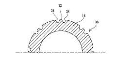
回転軸16のうち、軸孔26内に位置する部分は、インボリュートスプライン形状となっている。すなわち、回転軸16の当該箇所の外周には、径方向外側に突出する嵌合突起32(歯)と、径方向内側に陥没する嵌合溝34(歯溝)と、が周方向に連続して並ぶ外歯36が形成されている(図4参照)。この外歯36が、ロータコア12のコア内歯30と噛み合って嵌合することで、回転軸16がロータコア12に固定される。すなわち、回転軸16の嵌合突起32が、ロータコア12の嵌合溝34に、また、回転軸16の嵌合溝34が、ロータコア12の嵌合突起32に、それぞれ、嵌合することで、回転軸16がロータコア12に固定される。
A portion of the
そして、このように、嵌合突起32と嵌合溝34が嵌合することで、これら嵌合突起32および嵌合溝34を介して、ロータコア12と回転軸16との間で回転力が伝達される。換言すれば、本例によれば、ロータコア12と大径部38との摩擦力が小さくても、ロータコア12と回転軸16との間で回転力が伝達される。そのため、本例によれば、ロータコア12を軸方向に強く締め付けるナットが不要となり、ナットを締め付けるための設備が不要となる。結果として、ロータ10を製造する際のコストを低減できる。なお、本例では、ナットに替えて圧入リング18を設けているが、圧入リング18は、ナットに比べて取り付け工程が簡易であり、また、取り付けるための設備も比較的、安価に構成できる。
In this way, when the
ところで、この嵌合突起32と嵌合溝34が嵌合する嵌合部20c,20r(以下嵌合部20cと嵌合部20rを区別しないときは、単に「嵌合部20」という)が、ブリッジ部25の近くに存在すると、当該ブリッジ部25周辺に残留応力が発生しやすい。そして、かかる残留応力は、ブリッジ部25の劣化や損傷を招くことがある。
By the way, the
そこで、本例では、嵌合突起32と嵌合溝34とが嵌り合う嵌合部20を、ブリッジ部25と周方向に重複しない位置に配している。これについて、具体的に説明する。図4に示す通り、また、上述したとおり、回転軸16の外周面は、インボリュートスプライン形状であり、嵌合突起32(歯)と嵌合溝34(歯溝)が、全周に渡って連続している。一方、ロータコア12の軸孔26の内周面には、図3に示す通り、嵌合突起32および嵌合溝34が、間欠的に形成されている。より具体的には、軸孔26の内周面には、二つの嵌合突起32の間に一つの嵌合溝34が存在する突起と溝のセットが、周方向に間隔を開けて、8つ(すなわち磁極と同数)形成されている。一方、この突起と溝のセットが形成されていない箇所において、軸孔26の内径は、回転軸16の外径よりも大きくなっており、当該箇所において、軸孔26と回転軸16との嵌合は生じていない。したがって、この突起と溝のセットが存在する箇所が、回転軸16の嵌合突起/溝32,34と、軸孔26の嵌合溝/突起34,32と、が嵌合する嵌合部20となる。
Therefore, in this example, the
この嵌合部20は、図2に示す通り、ブリッジ部25と周方向に重複しない位置に設けられている。より具体的に説明すると、嵌合部20は、周方向に隣接する二つの磁極の間を通るq軸上に設けられている。本例では、全てのq軸上に嵌合部20を設けているため、嵌合部20の数は、磁極の数と同じになる。ただし、嵌合部20は、ブリッジ部25と周方向にズレているのであれば、その個数は、特に限定されない。ただし、嵌合に起因する応力の影響を均等化するためには、嵌合部20は、周方向に均等に配置されることが望ましい。また、嵌合部20の数は、磁極数の約数であることが望ましい。さらに、後述するように、嵌合部20として、周方向に嵌合する周側嵌合部20cと、径方向に嵌合する径側嵌合部20rと、設ける場合、周側嵌合部20cと径方向に嵌合する径側嵌合部20rとは、同数であり、嵌合部20全体の個数は、偶数であることが望ましい。
The
いずれにしても、嵌合部20を、ブリッジ部25と周方向にズレた位置に設けることで、嵌合部20と、ブリッジ部25との距離が大きくなる。そのため、嵌合に起因して生じる応力が、機械的強度が低下しているブリッジ部25に作用しにくくなる。その結果、ブリッジ部25に残留応力が生じにくく、ロータコア12の強度を高く維持できる。
In any case, the distance between the
ところで、本例では、嵌合部20として、主に周方向に嵌り合う周側嵌合部20cと、主に径方向に嵌り合う径側嵌合部20rと、を設けている。図2において、破線の楕円で囲った箇所は、周側嵌合部20cであり、破線の矩形で囲った箇所が径側嵌合部20rである。この周側嵌合部20cおよび径側嵌合部20rの構成について図5、図6を参照して説明する。
By the way, in this example, the peripheral side
図5は、周側嵌合部20cを説明する図である。図5においてハッチング範囲は、回転軸16を示している。図5の例では、回転軸16に、径方向外側に突出した嵌合突起32が、軸孔26に、径方向外側に陥没した嵌合溝34が形成されている。この嵌合突起32の径方向寸法は、嵌合溝34の径方向寸法と同じか、僅かに小さくなっている。一方、嵌合突起32の周方向寸法は、嵌合溝34の周方向寸法に比べて、僅かに大きくなっている。その結果、嵌合突起32と嵌合溝34は、周方向に密着しており、嵌合突起32と嵌合溝34との間で、周方向の動き、すなわち、回転が伝わるようになっている。このように嵌合突起32の周方向寸法が、嵌合溝34の周方向寸法より大きい周側嵌合部20cを設けることで、回転トルクが確実に伝達される。
FIG. 5 is a diagram for explaining the peripheral side
図6は、径側嵌合部20rを説明する図である。図6においても、ハッチング箇所が回転軸16を示しており、回転軸16に、嵌合突起32が、軸孔26に、嵌合溝34が形成されている。径側嵌合部20rでは、嵌合突起32の周方向寸法は、嵌合溝34の周方向寸法と同じか、僅かに小さくなっている。一方、嵌合突起32の径方向寸法は、嵌合溝34の径方向寸法よりも、僅かに大きくなっている。その結果、嵌合突起32と嵌合溝34は、周方向に密着することになる。かかる径側嵌合部20rを、周方向に2以上、より望ましくは3以上設けることで、容易に回転軸16の芯出しができる。
FIG. 6 is a diagram illustrating the radial side
本例では、図2に示す通り、周側嵌合部20c(破線楕円部)と径側嵌合部20r(破線矩形部)を、周方向に交互に配している。このように、2種類の嵌合部20を、交互に配することで、ロータコア12のかかる応力を均等に分散でき、ロータコア12にかかる負荷を軽減できる。
In this example, as shown in FIG. 2, the circumferential side
なお、これまで説明した構成は、一例であり、回転軸16の外周および軸孔26の内周の一方に形成された嵌合突起32が他方に形成された嵌合溝34に嵌合する嵌合部20が、ブリッジ部25と周方向に重複しない位置に設けられているのであれば、その他の構成は、適宜、変更されてもよい。例えば、本例では、回転軸16の外歯36を、嵌合突起32と嵌合溝34が連続して並ぶ歯車状(インボリュートスプライン状)としている。しかし、回転軸16の外歯36も、ロータコア12のコア内歯30と同様に、また、図7に示すように、嵌合突起32および/または嵌合溝34が、間欠的に並ぶ形状としてもよい。また、回転軸16の外歯36を、嵌合突起32および/または嵌合溝34が間欠的に並ぶ形状にするとともに、ロータコア12のコア内歯30を、嵌合突起32および嵌合溝34が連続的に並ぶ歯車状としてもよい。ただし、本例のように、回転軸16を歯車状とし、コア内歯30を突起/溝が間欠的に並ぶ形状としたほうが、1種類の回転軸16を、ブリッジ部25の位置や個数が異なる複数種類のロータコア12に適用することができる。
The configuration described so far is an example, and the
また、これまでの説明では、第一磁石孔22aと、第一磁束漏れ防止孔24aとの間に、ブリッジ部25が形成されるロータコア12を例に挙げた。しかし、ロータコア12は、周方向に近接して隣接する磁極用孔(磁石孔22および磁束漏れ防止孔24)の間に微小間隙であるブリッジ部25が形成されるのであれば、他の形態であってもよい。例えば、ロータコア12は、磁束漏れ防止孔を有さず、略V字状に配された二つの磁石孔を有する形態でもよい。この場合、一つの磁石孔の径方向内側端部と、隣接する磁石孔22a,22bの径方向内側端部と、の間の微小間隙がブリッジ部となる。また、これまでの説明では、嵌合突起および嵌合溝を、いずれも、略台形としているが、これらの形状は、適宜、変更されてもよい。
In the description so far, the
10 ロータ、12 ロータコア、14 永久磁石、16 回転軸、18 圧入リング、20 嵌合部、22 磁石孔、24 磁束漏れ防止孔、25 ブリッジ部、26 軸孔、28 カシメ部、30 コア内歯、32 嵌合突起、34 嵌合溝、36 外歯、38 大径部。
DESCRIPTION OF
Claims (1)
中心に延びる軸孔と、複数の磁極用孔と、を有するロータコアと、
前記磁極用孔に挿入された永久磁石と、
前記軸孔に挿通されて、1以上の嵌合部を介して前記軸孔に固定された回転軸と、
を備え、
前記嵌合部では、前記回転軸の外周面および前記軸孔の内周面の一方に設けられるとともに径方向に陥没する嵌合溝と、前記回転軸の外周面および前記軸孔の内周面の他方に設けられるとともに径方向に突出した嵌合突起と、が互いに嵌り合っており、
前記嵌合部は、周方向に近接する二つの磁極用孔間の微小間隙部であるブリッジ部と周方向に重複しない位置に配されている、
ことを特徴とする回転電機のロータ。
A rotor of a rotating electric machine,
A rotor core having a centrally extending axial hole and a plurality of magnetic pole holes;
A permanent magnet inserted into the magnetic pole hole;
A rotary shaft inserted into the shaft hole and fixed to the shaft hole via one or more fitting parts;
With
In the fitting portion, a fitting groove which is provided on one of the outer peripheral surface of the rotary shaft and the inner peripheral surface of the axial hole and which is recessed in the radial direction, the outer peripheral surface of the rotary shaft and the inner peripheral surface of the axial hole And fitting projections, which are provided on the other side of the housing and radially project, are fitted to each other,
The fitting portion is arranged at a position that does not overlap in the circumferential direction with a bridge portion that is a minute gap portion between two magnetic pole holes adjacent in the circumferential direction.
A rotor of a rotating electrical machine characterized by that.
Priority Applications (1)
| Application Number | Priority Date | Filing Date | Title |
|---|---|---|---|
| JP2018009882A JP7063637B2 (en) | 2018-01-24 | 2018-01-24 | Rotating machine rotor |
Applications Claiming Priority (1)
| Application Number | Priority Date | Filing Date | Title |
|---|---|---|---|
| JP2018009882A JP7063637B2 (en) | 2018-01-24 | 2018-01-24 | Rotating machine rotor |
Publications (2)
| Publication Number | Publication Date |
|---|---|
| JP2019129601A true JP2019129601A (en) | 2019-08-01 |
| JP7063637B2 JP7063637B2 (en) | 2022-05-09 |
Family
ID=67471461
Family Applications (1)
| Application Number | Title | Priority Date | Filing Date |
|---|---|---|---|
| JP2018009882A Active JP7063637B2 (en) | 2018-01-24 | 2018-01-24 | Rotating machine rotor |
Country Status (1)
| Country | Link |
|---|---|
| JP (1) | JP7063637B2 (en) |
Cited By (5)
| Publication number | Priority date | Publication date | Assignee | Title |
|---|---|---|---|---|
| JP2021045007A (en) * | 2019-09-13 | 2021-03-18 | アイシン・エィ・ダブリュ株式会社 | Rotor |
| JP2021045011A (en) * | 2019-09-13 | 2021-03-18 | アイシン・エィ・ダブリュ株式会社 | Rotor |
| JP6848135B1 (en) * | 2020-09-18 | 2021-03-24 | 株式会社東芝 | Rotor |
| DE102021205713A1 (en) | 2021-05-31 | 2022-12-01 | Valeo Eautomotive Germany Gmbh | Rotor for an electric machine |
| DE102021210755A1 (en) | 2021-09-27 | 2023-03-30 | Siemens Energy Global GmbH & Co. KG | Rotor for electric rotating machine, electric rotating machine, nacelle propulsion and watercraft |
Citations (6)
| Publication number | Priority date | Publication date | Assignee | Title |
|---|---|---|---|---|
| JP2005192288A (en) * | 2003-12-24 | 2005-07-14 | Okuma Corp | Rotor of reluctance motor |
| JP2006217770A (en) * | 2005-02-07 | 2006-08-17 | Oriental Motor Co Ltd | Fastening structure of rotor core to shaft of motor |
| JP2009153230A (en) * | 2007-12-18 | 2009-07-09 | Yaskawa Electric Corp | Method of manufacturing rotor core, rotor core manufactured by the manufacturing method, rotor core, embedded magnet type dynamo-electric machine having the rotor, vehicle, lift and working machine each using the dynamo-electric machine |
| JP2011147310A (en) * | 2010-01-18 | 2011-07-28 | Toyota Motor Corp | Rotor, and method and apparatus for manufacturing the same |
| JP2014072904A (en) * | 2012-09-27 | 2014-04-21 | Denso Corp | Dynamo-electric machine |
| JP2015104176A (en) * | 2013-11-22 | 2015-06-04 | トヨタ自動車株式会社 | Rotary electric machine rotor |
-
2018
- 2018-01-24 JP JP2018009882A patent/JP7063637B2/en active Active
Patent Citations (6)
| Publication number | Priority date | Publication date | Assignee | Title |
|---|---|---|---|---|
| JP2005192288A (en) * | 2003-12-24 | 2005-07-14 | Okuma Corp | Rotor of reluctance motor |
| JP2006217770A (en) * | 2005-02-07 | 2006-08-17 | Oriental Motor Co Ltd | Fastening structure of rotor core to shaft of motor |
| JP2009153230A (en) * | 2007-12-18 | 2009-07-09 | Yaskawa Electric Corp | Method of manufacturing rotor core, rotor core manufactured by the manufacturing method, rotor core, embedded magnet type dynamo-electric machine having the rotor, vehicle, lift and working machine each using the dynamo-electric machine |
| JP2011147310A (en) * | 2010-01-18 | 2011-07-28 | Toyota Motor Corp | Rotor, and method and apparatus for manufacturing the same |
| JP2014072904A (en) * | 2012-09-27 | 2014-04-21 | Denso Corp | Dynamo-electric machine |
| JP2015104176A (en) * | 2013-11-22 | 2015-06-04 | トヨタ自動車株式会社 | Rotary electric machine rotor |
Cited By (6)
| Publication number | Priority date | Publication date | Assignee | Title |
|---|---|---|---|---|
| JP2021045007A (en) * | 2019-09-13 | 2021-03-18 | アイシン・エィ・ダブリュ株式会社 | Rotor |
| JP2021045011A (en) * | 2019-09-13 | 2021-03-18 | アイシン・エィ・ダブリュ株式会社 | Rotor |
| JP6848135B1 (en) * | 2020-09-18 | 2021-03-24 | 株式会社東芝 | Rotor |
| WO2022059199A1 (en) * | 2020-09-18 | 2022-03-24 | 株式会社 東芝 | Rotor |
| DE102021205713A1 (en) | 2021-05-31 | 2022-12-01 | Valeo Eautomotive Germany Gmbh | Rotor for an electric machine |
| DE102021210755A1 (en) | 2021-09-27 | 2023-03-30 | Siemens Energy Global GmbH & Co. KG | Rotor for electric rotating machine, electric rotating machine, nacelle propulsion and watercraft |
Also Published As
| Publication number | Publication date |
|---|---|
| JP7063637B2 (en) | 2022-05-09 |
Similar Documents
| Publication | Publication Date | Title |
|---|---|---|
| JP7063637B2 (en) | Rotating machine rotor | |
| JP5310872B2 (en) | Rotor | |
| JP2007028868A (en) | Stator for rotary electric machine | |
| JP2007104819A (en) | Rotating electric machine | |
| WO2017119431A1 (en) | Rotating electric motor | |
| US20120200189A1 (en) | Rotating electrical machine | |
| WO2015050010A1 (en) | Rotor core, rotor, and rotary electric machine | |
| JP2007330030A (en) | Structure for fixing ring magnet in rotor and motor for electric power steering | |
| JP6801282B2 (en) | Rotating electric rotor | |
| CN112119572B (en) | Rotor of rotating electrical machine and rotor core support structure of rotating electrical machine | |
| JP4516392B2 (en) | Brushless motor rotor, brushless motor, and motor for power steering device | |
| JP2020058151A (en) | Rotor core | |
| JP2012222969A (en) | Rotor of rotary electric machine | |
| JP5495045B2 (en) | Rotating electrical machine rotor | |
| JP2014126048A (en) | Gear and electric motor using gear | |
| WO2015068846A1 (en) | Rotary electrical machine | |
| WO2019123962A1 (en) | Rotor and motor | |
| JP2017158313A (en) | Rotary electric machine and method of manufacturing the same | |
| JP2008167549A (en) | Rotor of rotary electric machine | |
| JP2014096869A (en) | Rotor of magnet embedded type motor | |
| US11063483B2 (en) | Electric motor | |
| WO2019123961A1 (en) | Rotor and motor | |
| JP3671928B2 (en) | Outer rotor structure of rotating electrical machine | |
| JP2018121407A (en) | Outer rotor type rotary electric machine | |
| JP2018007380A (en) | Rotary electric machine |
Legal Events
| Date | Code | Title | Description |
|---|---|---|---|
| A521 | Request for written amendment filed |
Free format text: JAPANESE INTERMEDIATE CODE: A523 Effective date: 20190704 |
|
| A711 | Notification of change in applicant |
Free format text: JAPANESE INTERMEDIATE CODE: A711 Effective date: 20190704 |
|
| A521 | Request for written amendment filed |
Free format text: JAPANESE INTERMEDIATE CODE: A821 Effective date: 20190704 |
|
| A621 | Written request for application examination |
Free format text: JAPANESE INTERMEDIATE CODE: A621 Effective date: 20200909 |
|
| A711 | Notification of change in applicant |
Free format text: JAPANESE INTERMEDIATE CODE: A712 Effective date: 20210423 |
|
| A977 | Report on retrieval |
Free format text: JAPANESE INTERMEDIATE CODE: A971007 Effective date: 20210709 |
|
| A131 | Notification of reasons for refusal |
Free format text: JAPANESE INTERMEDIATE CODE: A131 Effective date: 20210727 |
|
| A521 | Request for written amendment filed |
Free format text: JAPANESE INTERMEDIATE CODE: A523 Effective date: 20210914 |
|
| A131 | Notification of reasons for refusal |
Free format text: JAPANESE INTERMEDIATE CODE: A131 Effective date: 20220125 |
|
| A521 | Request for written amendment filed |
Free format text: JAPANESE INTERMEDIATE CODE: A523 Effective date: 20220316 |
|
| TRDD | Decision of grant or rejection written | ||
| A01 | Written decision to grant a patent or to grant a registration (utility model) |
Free format text: JAPANESE INTERMEDIATE CODE: A01 Effective date: 20220329 |
|
| A61 | First payment of annual fees (during grant procedure) |
Free format text: JAPANESE INTERMEDIATE CODE: A61 Effective date: 20220421 |
|
| R151 | Written notification of patent or utility model registration |
Ref document number: 7063637 Country of ref document: JP Free format text: JAPANESE INTERMEDIATE CODE: R151 |