JP3671928B2 - Outer rotor structure of rotating electrical machine - Google Patents
Outer rotor structure of rotating electrical machine Download PDFInfo
- Publication number
- JP3671928B2 JP3671928B2 JP2002098211A JP2002098211A JP3671928B2 JP 3671928 B2 JP3671928 B2 JP 3671928B2 JP 2002098211 A JP2002098211 A JP 2002098211A JP 2002098211 A JP2002098211 A JP 2002098211A JP 3671928 B2 JP3671928 B2 JP 3671928B2
- Authority
- JP
- Japan
- Prior art keywords
- magnet
- outer rotor
- rotor
- rotating electrical
- electrical machine
- Prior art date
- Legal status (The legal status is an assumption and is not a legal conclusion. Google has not performed a legal analysis and makes no representation as to the accuracy of the status listed.)
- Expired - Fee Related
Links
Images


Landscapes
- Permanent Field Magnets Of Synchronous Machinery (AREA)
Description
【0001】
【発明の属する技術分野】
この発明は、インナーロータおよびアウターロータの両ロータを具え、電動機および発電機として機能する回転電機のアウターロータ構造に関し、とくに、インナーロータの磁路内の磁場抵抗を低下させてインナーロータの出力を高める技術を提案するものである。
【0002】
【従来の技術】
ステータを隔てて配置されて、ステータのコイルを共用するインナーロータおよびアウターロータのそれぞれに、周方向に間隔をおいて複数の磁石を配設するとともに、アウターロータの磁石数をインナーロータのそれより多くしてなる従来のこの種の回転電機としては、たとえば、特開2001−78408号公報、特開2001−112221号公報および特開2001−231227号公報等に開示されたものがある。
【0003】
【発明が解決しようとする課題】
しかるに、これらのいずれの従来技術にあっても、ロータなかでもアウターロータに配設される磁石の形状、配置位置および、磁石の側部に設けられてその磁石の洩れ磁束の低減をもたらすエアギャップの形状、配設状態等についての十分な考慮がなされていなかったので、それらの従来技術は、二重ロータ回転電機としての最適な磁路を提供するものではなかった。
【0004】
この発明は、従来技術のこのような実情を鑑みてなされたものであり、それの目的とするところは、とくに、アウターロータの磁石および、その側部に隣接するエアギャップの形状、配置状態等を検討することにより、アウターロータの出力性能を十分高く維持しつつ、インナーロータの出力を高めることができる回転電機のアウターロータ構造を提供するにある。
【0005】
【課題を解決するための手段】
これがため、本願の請求項1に係る発明は、ステータを隔てて半径方向の内外に位置して、ステータのコイルを共用するともに同軸のインナーロータおよびアウターロータを具え、それぞれのロータが、周方向に間隔をおいて位置する複数個の磁石を有し、磁石の総数を、アウターロータでインナーロータより多くしてなる回転電機において、アウターロータのコア内に、そのロータの軸線方向への延在姿勢で各磁石、多くは永久磁石を配設するとともに、アウターロータ軸線と直交する断面内で、磁石の両側部に区画されるエアギャップの、半径方向の最大隙間を、磁石の同方向の最大厚みより小さくしてなる。
【0006】
ここでより好ましくは、請求項2に記載したように、磁石の両側部に区画されるエアギャップより半径方向内側に位置する、磁石の両側部部分に、半径方向内側に向けて漸次狭幅となるテーパ面を設ける。
【0007】
本願の請求項3に係る発明は、とくに、アウターロータのコア内に、そのロータの軸線方向への延在姿勢で磁石を配設するとともに、アウターロータ軸線と直交する断面内で、磁石の両側部に区画されるそれぞれのエアギャップの半径方向の外縁を、磁石から遠ざかるにつれて、アウターロータの外周、より直接的にはアウターロータコアの外周から次第に離隔する方向に曲がる曲線形状、多くは円弧形状としたものである。
【0008】
また、本願の請求項4に係る発明は、とくに、アウターロータのコア内に、そのロータの軸線方向への延在姿勢で磁石を配設するとともに、アウターロータ軸線と直交する断面内で、磁石の両側部に区画されるそれぞれのエアギャップの、磁石、ひいては、その側壁と隣接する位置での半径方向の最大間隙を、磁石の、側壁位置での最小厚みと等しくしたものである。
そしてさらに好ましくは、請求項5に記載したように、請求項1〜4のそれぞれに記載したアウターロータ構造の二種以上を組合わせた構造とする。
【0009】
【発明の効果】
内外二重ロータ構造の回転電機では、アウターロータは、インナーロータが発生する磁束の磁路を形成する役割を担っているので、アウターロータ内の磁場抵抗を低減させることにより、インナーロータの磁束が増加してインナーロータの出力が増加する。
【0010】
ここで、アウターロータ内の磁場抵抗の増加に大きく影響を及ぼす要因は、アウターロータの磁石および、磁石の側部に区画されるエアギャップの存在にある。従って、それらをともに削減すれば、アウターロータ内の磁場抵抗は低減されることになるも、アウターロータの磁石の削減は、アウターロータそれ自身の出力低下をもたらすことになり、また、その磁石の厚みの低減は、磁石内の磁束密度の低下につながり、減磁耐力の低下をもたらすことになる。
【0011】
そこで、請求項1に係る発明は、アウターロータの磁石の、体積および厚みを十分に確保しつつ、磁石の側部に位置するエアギャップの、半径方向の最大間隙を相対的に低減させることにより、アウターロータの性能はそのままに、インナーロータの磁路を形成するアウターロータ内の磁場抵抗を有利に低減させて、インナーロータの出力増加を実現する。
【0012】
ここで、請求項2に係るように、磁石の両側部に区画されるエアギャップより半径方向内方側に位置する、磁石の両側部部分に、たとえば面取り加工によって、半径方向内側に向けて漸次狭幅となるテーパ面を設けた場合には、磁石に面取り加工を施さない場合に比し、インナーロータの磁路内の磁石体積を減少させて、インナーロータ磁束に対する磁場抵抗を低下させることができ、この結果として、インナーロータの出力がより高まることになる。
【0013】
またこの場合には、磁石のテーパ面の作用下で、アウターロータの回転に伴う、磁束密度の急激な変化を抑制することで、トルクリップルを有効に低減させることができ、さらには、磁石の、アウターロータコアの磁石配置孔への嵌め込みによって、それのテーパ面を磁石配置孔の壁面に面接触させることにより、特別の磁石支持部材や接着剤の必要なしに、また、磁石コストおよび重量の増加なしに、磁石をアウターロータコアに固定することができ、併せて、アウターロータの高速回転に伴う、コアの磁石配置孔隅部への応力の発生を緩和することもできる。
【0014】
ところで、アウターロータ軸線と直交する断面内で、それぞれのエアギャップの、半径方向の外縁を、請求項3に記載したように、磁石から遠ざかるにつれて、アウターロータの外周から次第に離隔する方向に曲がる曲線形状としたときは、エアギャップ間隙を、ロータの周方向にほぼ一定とする場合に比し、インナーロータの磁路内のギャップ隙間を減少させることができ、これにより、インナーロータ磁束の磁場抵抗を小さくして、インナーロータの出力を高めることができる。そして、このことによれば、アウターロータの回転に伴ってエアギャップ外縁に発生する応力を緩和して、アウターロータの一層の高速回転を可能とするもこともできる。
【0015】
このようなアウターロータ磁石およびエアギャップの相対関係につき、請求項4に記載したように、それぞれのエアギャップの、磁石の側壁と隣接する位置での半径方向の最大間隙を、磁石の、最も薄肉となるその側壁位置の最小厚みと等しくした場合には、磁石の側壁部の薄肉化に基づいて、いいかえれば、ロータコアの、たとえば鋼板部分体積増加に基づいて、インナーロータ磁路での磁場抵抗を低下させることができ、これによってインナーロータの出力を高めることができる。
【0016】
なおこの場合は、磁石の洩れ磁束は、磁石の厚みが最も薄く、磁石のN極とS極との距離がとくに近くなるその側壁部で最も増加することになるも、ここでは、磁石が最小厚みとなるそれの側壁位置での厚みを、エアギャップの最大間隙と等しくすることにより、洩れ磁束を最小のエアギャップをもって有効に抑制することができ、結果として、アウターロータの出力を高めることができる。
そして、これらのことは、先に述べたアウターロータ構造の二種以上を組合わせた場合に、とくに顕著なものとなる。
【0017】
【発明の実施の形態】
以下にこの発明の実施の形態を図面に示すところに基づいて説明する。
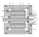
図1は、この発明に係る構造を具える回転電機を示す、軸線方向の略線断面図であり、図2は、図1の中心軸線と直交する断面内での半部断面図である。
【0018】
図1に示す複合電流多層モータは、一個の円筒状のステータ1と、このステータ1を隔てて、それの半径方向の内外に同軸に配置されて、スタータ1のコイルを共用するインナーロータ2およびアウターロータ3との三重構造になり、それらのそれぞれをハウジング4内に収納してなる。
【0019】
ハウジング4内へのこの収納に当たっては、アウターロータ3の外周側に取付けたトルク伝達シェル5の両端を、それぞれのベアリング6,7を介してハウジング4に回転自在に支持し、また、そのトルク伝達シェル5を、ベアリング7の側で中空のアウターロータシャフト8に連続させる。
【0020】
そして、インナーロータ2は、その中心に貫通させて固定したインナーロータシャフト9の一端を、ベアリング10を介してハウジング4に、また、その他端を、ベアリング11を介して中空のアウターロータシャフト8にそれぞれ支持することで、それらに対して回転自在に配設する。
【0021】
ところで、ステータ1は、それの、アウターロータシャフト8の存在側の端部ではハウジング4に支持させることができないので、たとえば図示のように、スタータ1をその軸線方向に貫通するボルト12,13により、アウターロータシャフト8とは反対側のハウジング端壁に締付け固定して、ハウジング4に片持ち支持させる。
【0022】
ここで、ステータ1は、たとえば、電磁鋼板をプレス加工してなる、図2に示すようなほぼT字状のステータ鋼板21をスタータの軸線方向に積層してステータピース22とし、各ステータピース22にコイル23を巻線するとともに、巻線を終えたそれぞれのステータピース22を、円周方向に等間隔に配置することによりスタータコアとし、このステータコアの全体を、樹脂材料でモールディンクして一体化することにより構成する。
なお、前述したステータ固定用のボルト12,13は、相互に隣接するステータピース22間で樹脂部に貫通して延在する。
【0023】
また、インナーロータ2は、これもたとえば電磁鋼板をプレス加工してなり、図2に示すように同一円周上に複数の開口を有する円板状板材24を、各開口が相互に重なり合うようにロータの軸線方向に積層してなるロータコア25に対し、それぞれの開口により形成されて軸線方向に延びる磁石配置孔26内へ永久磁石27を挿入固定することにより構成する。
【0024】
そしてまた、アウターロータ3は、電磁鋼板等をプレス加工して、同一円周上に複数の開口を穿設した図2に示すような円環状板材28を、開口が重なり合う姿勢でロータの軸線方向に積層してなるロータコア29に対し、それぞれの開口により区画されて軸線方向に延びる磁石配置孔30内へ永久磁石31を挿入固定するとともに、その磁石配置孔30、ひいては、永久磁石31のそれぞれの側部に、これも、前記開口の重なり合いによって区画されるエアギャップ32を設けてなる。
【0025】
このような基本構造を具える回転電機において、この実施形態では、図3に要部を拡大して示すように、アウターロータ3に設けたエアギャップ32の、半径方向の最大間隙δを、永久磁石31の半径方向の最大厚みTより小さくし、より好ましくは、永久磁石31の、エアギャップ32より半径方向内側に位置する両側部部分に、面取り加工その他によって、図示の断面内で半径方向内側に向けて漸次狭幅となるテーパ面33を設ける。
【0026】
前者によれば、永久磁石31の厚みを低減させることなく、エアギャップ32の最大間隙を減じることで、アウターロータ3の性能はそのままに、図1に閉曲線Aで示す、インナーロータ2の磁路内でのアウターロータ3の磁場抵抗を有効に低下させることができる。
【0027】
そして後者によれば、インナーロータ2の磁路内の磁石体積の減少に基づいて、これもまたアウターロータ3の磁場抵抗を有利に低下させることができる。またここでは、永久磁石31の両側部部分に設けたテーパ面33を、ロータコア29に形成した磁石配置孔30内へ面接触下で嵌め合わせてその磁石31を固定することにより、アウターロータ3が高速回転しても、応力の集中なしに磁石31を拘束することができる。
いいかえれば、磁石配置孔等に、磁石の固定のための突起等を別途設けた場合には、アウターロータの高速回転に伴う遠心力によって、突起等に大きな応力が発生するうれいがある。
【0028】
しかも、テーパ面33を設けない場合には、磁石のある場所とない場所との磁場抵抗が大きく異なり、多くは、ステータに鎖交する磁束が急変することに起因してトルクリップルが発生することになるところ、テーパ面33を設けた場合には、ステータからみた、磁石による磁場抵抗の変化が緩やかになり、しかも、ステータアウターロータ側ヨーク端部22aにおける磁束の集中が緩和されるので、トルクリップルが減少するという効果がある。
【0029】
ところで、ここにおけるテーパ面33は、磁石配置孔の壁面と正確に整合する、半径方向内側もしくは外側に凸となる曲面とすることも可能であるが、加工性、製造コスト等を考慮したときはテーパ面とすることが有利である。
【0030】
また、他の実施形態では、それぞれのエアギャップ32の半径方向の外縁を、磁石31から遠ざかるにつれて、ロータコア29の外周から次第に離隔する方向に曲がってギャップ間隙を次第に狭める曲線形状、図では円弧状部分34により形成する。なお、エアギャップ32の内縁は、図示のように直線状に形成することができる。
【0031】
ここで、エアギャップ上縁の円弧状部分34は、先に述べたように、エアギャップ体積を減少させるべく機能するので、インナーロータ2の磁路内の磁場抵抗の低下に有効に寄与することになる。この一方で、永久磁石31の洩れ磁束が最も多くなる磁石31の側部では、円弧状部分34を設けてなお、十分なエアギャップ間隙を確保することができるので、アウターロータ3の性能は高く維持することができる。
【0032】
加えて、上記円弧状部分34は、アウターロータ3の高速回転に際し、エアギャップの外縁への応力集中を防止するとともに、応力分散に基づく平均応力の低下をもたらすので、アウターロータ3の一層の高速回転を可能にすることができる。すなわち、ロータを高速回転させる場合には、磁石に隣接するエアギャップの形状によってアウターロータの内部応力が変化し、とくに、エアギャップの外縁周辺の応力は、エアギャップ内縁のそれより高くなるので、その外縁に角部が存在するときは、そこへの応力集中によってロータが破壊されるおそれがあるところ、エアギャプ外縁を円弧状部分34によって形成したときは、このようなおそれを十分に取り除くことができる。
【0033】
図4はさらに、他の実施形態を示す図3と同様の図であり、これは、それぞれのエアギャップ32の、磁石31の側壁と隣接する位置での半径方向の最大間隙δを、磁石それ自身の、側壁位置での最小厚みtと等しくしたものである。
これによれば、磁石31の側壁部での磁石厚みの低減により、たとえば図3に示す場合に比して、インナーロータ磁路内の磁場抵抗を一層低下させることができ、また、磁石31の洩れ磁束を、最小のエアギャップ間隙を持って十分に抑制し得る利点がある。
【0034】
以上この発明の実施の形態を図面に示すところに基いて説明したが、上述した各構成のそれぞれを組み合わせて、永久磁石31とエアギャップ32とを図4に示すような相対構成としたときは、インナーロータ2の出力をより一層高めることができる。
【図面の簡単な説明】
【図1】 この発明の実施の形態になるアウターロータ構造を具える回転電機の軸線方向略線断面図である。
【図2】 図1の中心軸線と直交する断面内での半部断面図である。
【図3】 図2の要部拡大図である。
【図4】 他の実施形態を示す図3と同様の図である。
【符号の説明】
1 ステータ
2 インナーロータ
3 アウターロータ
29 ロータコア
30 磁石配置孔
31 永久磁石
32 エアギャップ
33 テーパ面
34 円弧状部分
T 最大厚み
t 最小厚み
δ 最大間隙[0001]
BACKGROUND OF THE INVENTION
The present invention relates to an outer rotor structure of a rotating electrical machine that includes both an inner rotor and an outer rotor and functions as an electric motor and a generator, and in particular, reduces the magnetic field resistance in the magnetic path of the inner rotor to reduce the output of the inner rotor. It proposes technology to enhance.
[0002]
[Prior art]
A plurality of magnets are arranged at intervals in the circumferential direction on each of the inner rotor and the outer rotor that are arranged with a stator and share the stator coil, and the number of magnets of the outer rotor is set to be smaller than that of the inner rotor. Examples of this type of conventional rotating electric machine which are increased include those disclosed in Japanese Patent Application Laid-Open Nos. 2001-78408, 2001-112221, and 2001-231227, for example.
[0003]
[Problems to be solved by the invention]
However, in any of these prior arts, the shape and position of the magnet disposed on the outer rotor of the rotor, and the air gap provided on the side of the magnet to reduce the leakage flux of the magnet. Since sufficient consideration has not been given to the shape, arrangement state, and the like, those conventional techniques have not provided an optimum magnetic path as a double rotor rotating electric machine.
[0004]
The present invention has been made in view of such circumstances of the prior art, and the object of the present invention is, in particular, the shape of the outer rotor magnet and the air gap adjacent to its side, the arrangement state, etc. Is to provide an outer rotor structure for a rotating electrical machine that can increase the output of the inner rotor while maintaining the output performance of the outer rotor sufficiently high.
[0005]
[Means for Solving the Problems]
For this reason, the invention according to
[0006]
More preferably, as described in
[0007]
In the invention according to
[0008]
In addition, the invention according to
More preferably, as described in
[0009]
【The invention's effect】
In a rotating electric machine having an inner / outer double rotor structure, the outer rotor plays a role of forming a magnetic path of magnetic flux generated by the inner rotor, so that the magnetic flux of the inner rotor is reduced by reducing the magnetic field resistance in the outer rotor. Increase the output of the inner rotor.
[0010]
Here, the factor that greatly affects the increase in the magnetic field resistance in the outer rotor is the presence of the magnet of the outer rotor and the air gap defined on the side of the magnet. Therefore, if both of them are reduced, the magnetic field resistance in the outer rotor will be reduced, but the reduction of the magnet of the outer rotor will lead to a decrease in the output of the outer rotor itself, The reduction in thickness leads to a decrease in magnetic flux density in the magnet, resulting in a decrease in demagnetization resistance.
[0011]
Therefore, the invention according to
[0012]
Here, as claimed in
[0013]
In this case, the torque ripple can be effectively reduced by suppressing a sudden change in the magnetic flux density accompanying the rotation of the outer rotor under the action of the taper surface of the magnet. By fitting the outer rotor core into the magnet placement hole, the taper surface of the outer rotor core is brought into surface contact with the wall surface of the magnet placement hole, thereby eliminating the need for a special magnet support member or adhesive, and increasing the magnet cost and weight. Without being able to fix the magnet to the outer rotor core, it is also possible to alleviate the generation of stress at the corners of the magnet magnets where the outer rotor rotates at a high speed.
[0014]
By the way, in the cross section orthogonal to the outer rotor axis, the curved outer edge of each air gap bends away from the outer periphery of the outer rotor as the distance from the magnet increases. When the shape is used, the gap gap in the magnetic path of the inner rotor can be reduced compared to the case where the air gap gap is substantially constant in the circumferential direction of the rotor. Can be reduced to increase the output of the inner rotor. And according to this, the stress which generate | occur | produces in an air gap outer edge with rotation of an outer rotor is relieve | moderated, and it can also make the outer rotor further high-speed rotation.
[0015]
With respect to the relative relationship between the outer rotor magnet and the air gap, as described in
[0016]
In this case, the leakage flux of the magnet is the smallest at the side wall where the thickness of the magnet is the smallest and the distance between the north and south poles of the magnet is particularly short. By making the thickness at the side wall position, which is the thickness, equal to the maximum gap of the air gap, the leakage magnetic flux can be effectively suppressed with the minimum air gap, and as a result, the output of the outer rotor can be increased. it can.
These are particularly remarkable when two or more types of the outer rotor structure described above are combined.
[0017]
DETAILED DESCRIPTION OF THE INVENTION
Embodiments of the present invention will be described below based on the drawings.
FIG. 1 is a schematic cross-sectional view in the axial direction showing a rotating electrical machine having a structure according to the present invention, and FIG. 2 is a half-sectional view in a cross section orthogonal to the central axis of FIG.
[0018]
A composite current multilayer motor shown in FIG. 1 includes a single
[0019]
In this housing in the
[0020]
The
[0021]
Incidentally, since the
[0022]
Here, the
The
[0023]
The
[0024]
Further, the
[0025]
In the rotating electrical machine having such a basic structure, in this embodiment, as shown in an enlarged view of the main part in FIG. 3, the radial maximum gap δ of the
[0026]
According to the former, by reducing the maximum gap of the
[0027]
And according to the latter, based on the reduction of the magnet volume in the magnetic path of the
In other words, when a projection or the like for fixing the magnet is separately provided in the magnet arrangement hole or the like, a large stress may be generated on the projection or the like due to the centrifugal force accompanying the high-speed rotation of the outer rotor.
[0028]
In addition, when the tapered
[0029]
By the way, the
[0030]
In another embodiment, the outer edge of each
[0031]
Here, as described above, the arc-shaped
[0032]
In addition, the arc-shaped
[0033]
FIG. 4 is a view similar to FIG. 3 showing another embodiment, which shows the maximum radial gap δ of each
According to this, the magnetic field resistance in the inner rotor magnetic path can be further reduced by reducing the magnet thickness at the side wall portion of the
[0034]
The embodiment of the present invention has been described based on the drawings. However, when the
[Brief description of the drawings]
FIG. 1 is a schematic cross-sectional view in the axial direction of a rotating electrical machine having an outer rotor structure according to an embodiment of the present invention.
2 is a half cross-sectional view in a cross section orthogonal to the central axis of FIG. 1;
FIG. 3 is an enlarged view of a main part of FIG.
FIG. 4 is a view similar to FIG. 3 showing another embodiment.
[Explanation of symbols]
DESCRIPTION OF
Claims (5)
アウターロータのコア内に、そのロータの軸線方向への延在姿勢で磁石を配設するとともに、アウターロータ軸線と直交する断面内で、磁石の両側部に区画されるエアギャップの、半径方向の最大間隙を、磁石の同方向の最大厚みより小さくしてなる回転電機のアウターロータ構造。In a rotating electrical machine comprising an inner rotor and an outer rotor that are located inside and outside in the radial direction across a stator and share a coil, and each rotor has a plurality of magnets positioned at intervals in the circumferential direction,
A magnet is disposed in the core of the outer rotor so as to extend in the axial direction of the rotor, and the radial direction of the air gap defined on both sides of the magnet in the cross section orthogonal to the outer rotor axial line. An outer rotor structure for a rotating electrical machine in which the maximum gap is smaller than the maximum thickness in the same direction of the magnet.
アウターロータのコア内に、そのロータの軸線方向への延在姿勢で磁石を配設するとともに、アウターロータ軸線と直交する断面内で、磁石の両側部に区画されるそれぞれのエアギャップの半径方向の外縁を、磁石から遠ざかるにつれて、アウターロータの外周から次第に離隔する方向に曲がる曲線形状としてなる回転電機のアウターロータ構造。In a rotating electrical machine comprising an inner rotor and an outer rotor that are located inside and outside in the radial direction across a stator and share a coil, and each rotor has a plurality of magnets positioned at intervals in the circumferential direction,
In the core of the outer rotor, the magnet is disposed in a posture extending in the axial direction of the rotor, and the radial direction of each air gap defined on both sides of the magnet in a cross section orthogonal to the outer rotor axial line An outer rotor structure for a rotating electrical machine that has a curved shape that gradually curves away from the outer periphery of the outer rotor as the outer edge of the rotor moves away from the magnet.
アウターロータのコア内に、そのロータの軸線方向への延在姿勢で磁石を配設するとともに、アウターロータ軸線と直交する断面内で、磁石の両側部に区画されるそれぞれのエアギャップの、磁石と隣接する位置での半径方向の最大間隙を、磁石の、側壁位置での最小厚みと等しくしてなる回転電機のアウターロータ構造。In a rotating electrical machine comprising an inner rotor and an outer rotor that are located inside and outside in the radial direction across a stator and share a coil, and each rotor has a plurality of magnets positioned at intervals in the circumferential direction,
A magnet is disposed in the outer rotor core in a posture extending in the axial direction of the rotor, and each air gap magnet is defined on both sides of the magnet in a cross section orthogonal to the outer rotor axial line. Outer rotor structure of a rotating electrical machine in which the maximum radial gap at a position adjacent to the magnet is equal to the minimum thickness of the magnet at the side wall position.
Priority Applications (1)
| Application Number | Priority Date | Filing Date | Title |
|---|---|---|---|
| JP2002098211A JP3671928B2 (en) | 2002-04-01 | 2002-04-01 | Outer rotor structure of rotating electrical machine |
Applications Claiming Priority (1)
| Application Number | Priority Date | Filing Date | Title |
|---|---|---|---|
| JP2002098211A JP3671928B2 (en) | 2002-04-01 | 2002-04-01 | Outer rotor structure of rotating electrical machine |
Publications (2)
| Publication Number | Publication Date |
|---|---|
| JP2003299326A JP2003299326A (en) | 2003-10-17 |
| JP3671928B2 true JP3671928B2 (en) | 2005-07-13 |
Family
ID=29387888
Family Applications (1)
| Application Number | Title | Priority Date | Filing Date |
|---|---|---|---|
| JP2002098211A Expired - Fee Related JP3671928B2 (en) | 2002-04-01 | 2002-04-01 | Outer rotor structure of rotating electrical machine |
Country Status (1)
| Country | Link |
|---|---|
| JP (1) | JP3671928B2 (en) |
Families Citing this family (2)
| Publication number | Priority date | Publication date | Assignee | Title |
|---|---|---|---|---|
| US9431884B2 (en) * | 2013-03-26 | 2016-08-30 | Caterpillar Inc. | Dual rotor switched reluctance machine |
| CN109742917A (en) * | 2019-02-28 | 2019-05-10 | 郑州大学 | A kind of birotor permanent magnetic synchronous electric motor rotor fixed structure |
-
2002
- 2002-04-01 JP JP2002098211A patent/JP3671928B2/en not_active Expired - Fee Related
Also Published As
| Publication number | Publication date |
|---|---|
| JP2003299326A (en) | 2003-10-17 |
Similar Documents
| Publication | Publication Date | Title |
|---|---|---|
| US9071118B2 (en) | Axial motor | |
| US7411330B2 (en) | Rotating electric machine | |
| US7804216B2 (en) | Permanent-magnet reluctance electrical rotary machine | |
| JP4995459B2 (en) | motor | |
| JP2012120326A (en) | Interior magnet rotor, motor, and method for assembling motor | |
| JP2007014110A (en) | Rotary electric machine | |
| JP6022077B2 (en) | Rotor for rotating electrical machines | |
| EP3402041B1 (en) | Rotating electric motor | |
| WO2020230507A1 (en) | Rotor and motor provided with same | |
| WO2018037652A1 (en) | Consequent pole-type rotor, electric motor, and air conditioner | |
| JP2009273304A (en) | Rotor of rotating electric machine, and rotating electric machine | |
| JP2006271142A (en) | Rotary machine | |
| JP2009261162A (en) | Split stator core | |
| JP2013027157A (en) | Inner rotor type electric rotating machine and compressor | |
| JP2011172359A (en) | Split rotor and electric motor | |
| JP2005333762A (en) | Rotating electric machine and its rotor | |
| WO2017212575A1 (en) | Permanent magnet motor | |
| JP3671928B2 (en) | Outer rotor structure of rotating electrical machine | |
| US11594923B2 (en) | Rotor and motor including the same | |
| TW201742356A (en) | Axial gap type rotary electric machine | |
| JP2020108277A (en) | Rotor of dynamo-electric machine | |
| US20180138773A1 (en) | Rotor | |
| WO2017175461A1 (en) | Axial gap rotary electric machine | |
| WO2024084542A1 (en) | Rotary electric machine | |
| JP2004080950A (en) | Armature of dynamo-electric machine |
Legal Events
| Date | Code | Title | Description |
|---|---|---|---|
| A977 | Report on retrieval |
Free format text: JAPANESE INTERMEDIATE CODE: A971007 Effective date: 20041221 |
|
| A131 | Notification of reasons for refusal |
Free format text: JAPANESE INTERMEDIATE CODE: A131 Effective date: 20050104 |
|
| TRDD | Decision of grant or rejection written | ||
| A01 | Written decision to grant a patent or to grant a registration (utility model) |
Free format text: JAPANESE INTERMEDIATE CODE: A01 Effective date: 20050329 |
|
| A61 | First payment of annual fees (during grant procedure) |
Free format text: JAPANESE INTERMEDIATE CODE: A61 Effective date: 20050411 |
|
| R150 | Certificate of patent or registration of utility model |
Free format text: JAPANESE INTERMEDIATE CODE: R150 |
|
| FPAY | Renewal fee payment (event date is renewal date of database) |
Free format text: PAYMENT UNTIL: 20090428 Year of fee payment: 4 |
|
| FPAY | Renewal fee payment (event date is renewal date of database) |
Free format text: PAYMENT UNTIL: 20090428 Year of fee payment: 4 |
|
| FPAY | Renewal fee payment (event date is renewal date of database) |
Free format text: PAYMENT UNTIL: 20100428 Year of fee payment: 5 |
|
| FPAY | Renewal fee payment (event date is renewal date of database) |
Free format text: PAYMENT UNTIL: 20110428 Year of fee payment: 6 |
|
| LAPS | Cancellation because of no payment of annual fees |