WO2017175461A1 - Axial gap rotary electric machine - Google Patents
Axial gap rotary electric machine Download PDFInfo
- Publication number
- WO2017175461A1 WO2017175461A1 PCT/JP2017/003507 JP2017003507W WO2017175461A1 WO 2017175461 A1 WO2017175461 A1 WO 2017175461A1 JP 2017003507 W JP2017003507 W JP 2017003507W WO 2017175461 A1 WO2017175461 A1 WO 2017175461A1
- Authority
- WO
- WIPO (PCT)
- Prior art keywords
- magnet
- axial gap
- gap type
- rotating electrical
- type rotating
- Prior art date
Links
Images


Classifications
-
- H—ELECTRICITY
- H02—GENERATION; CONVERSION OR DISTRIBUTION OF ELECTRIC POWER
- H02K—DYNAMO-ELECTRIC MACHINES
- H02K1/00—Details of the magnetic circuit
- H02K1/06—Details of the magnetic circuit characterised by the shape, form or construction
- H02K1/22—Rotating parts of the magnetic circuit
-
- H—ELECTRICITY
- H02—GENERATION; CONVERSION OR DISTRIBUTION OF ELECTRIC POWER
- H02K—DYNAMO-ELECTRIC MACHINES
- H02K1/00—Details of the magnetic circuit
- H02K1/06—Details of the magnetic circuit characterised by the shape, form or construction
- H02K1/22—Rotating parts of the magnetic circuit
- H02K1/27—Rotor cores with permanent magnets
-
- H—ELECTRICITY
- H02—GENERATION; CONVERSION OR DISTRIBUTION OF ELECTRIC POWER
- H02K—DYNAMO-ELECTRIC MACHINES
- H02K21/00—Synchronous motors having permanent magnets; Synchronous generators having permanent magnets
- H02K21/12—Synchronous motors having permanent magnets; Synchronous generators having permanent magnets with stationary armatures and rotating magnets
- H02K21/24—Synchronous motors having permanent magnets; Synchronous generators having permanent magnets with stationary armatures and rotating magnets with magnets axially facing the armatures, e.g. hub-type cycle dynamos
Definitions
- the present invention relates to an axial gap type rotating electric machine, and more particularly to a structure of a rotor of the rotating electric machine.
- An axial gap type rotating electrical machine includes a stator and a rotor arranged in the direction of the rotation axis via the stator and a predetermined gap (gap).
- the rotor includes a plurality of permanent magnets arranged in the circumferential direction and a holding member that holds the magnets.
- ⁇ Axial gap type rotating electrical machines increase output by widening the facing area between the stator and the rotor.
- the output can be increased by increasing the magnetic force of the permanent magnet.
- the holding structure described in Patent Document 1 since the taper or notch is provided, the surface area of the magnet facing the stator is reduced, which causes a reduction in torque and efficiency of the rotating electrical machine.
- the holding structure described in Patent Document 2 has a structure in which a protrusion is provided in the gap portion to hold the magnet, and the gap length increases by the thickness of the protrusion. Incurring a decrease is a problem.
- the present invention provides an axial gap type rotating electrical machine that can reduce the magnet surface area and increase the gap length, and can secure the holding strength against the axial attractive force of the magnet. With the goal.
- the magnet arranged on the rotor A notch is provided on the inner diameter side or the outer periphery side and in the middle of the axial direction, and a projection that fits the notch of the magnet is provided on a yoke that holds the magnet.
- the present invention it is possible to reduce the possibility of causing a decrease in the magnet surface area and an increase in the gap length, and it is possible to hold the magnet against the axial attractive force while suppressing a decrease in the torque and efficiency of the motor. .
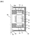
- the perspective view of the axial gap type rotary electric machine of embodiment of this invention Sectional drawing of the axial gap type rotary electric machine of embodiment of this invention.
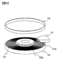
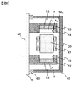
- FIGS. 1 and 2 are perspective views for explaining the basic configuration of a two-rotor type axial gap rotating electrical machine to which the present invention is applied.
- the axial gap type rotating electrical machine 1 is arranged so that a pair of disk-shaped rotors 10 face each other in the direction of the rotation axis 50, and a predetermined gap is interposed between the pair of rotors 10.
- the stator 20 is sandwiched.
- the stator 20 includes a plurality of cores 22 arranged in the circumferential direction and coils 21 wound around the cores, and is held on the housing 40 by, for example, a resin mold or a mechanical part (not shown).
- the core 21 is composed of a laminated body of magnetic thin plates such as electromagnetic steel plates and amorphous foil strips, and the magnetic thin plates are insulated by insulating layers.
- the rotor 10 includes a yoke 12 having a recess in the axial direction, and a rotor core 13 disposed in each recess.
- the rotor core 13 is installed in the concave portion of the yoke 12 by adhesion, for example.
- the present invention is not limited to the above-described two-rotor axial gap type rotating electrical machine.
- a pair of stators are arranged so as to face each other in the axial direction, and the rotor is interposed through a predetermined gap.
- It can also be applied to a two-stator type axial gap type rotating electrical machine in which a stator is arranged and a one-rotor one-stator type axial gap type rotating electrical machine in which one stator and a rotor are arranged with a predetermined gap. Needless to say.
- embodiments relating to the rotor structure will be described.
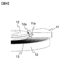
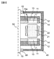
- Example (1) 2 to 4 show the rotor structure of the axial gap type rotating electric machine according to the first embodiment.
- the protrusion 12 a is provided on the inner diameter side of the yoke 12, and the notch 11 a is provided on the inner diameter side of the magnet 11.
- the magnet 11 is inserted from the outer diameter side and arranged so that the notch 11a fits into the protrusion 12a.
- an outer ring 14 is provided on the outer diameter side of the magnet 11.
- the magnet 11 and the rotor core 13 may be fixed by an adhesive force of an adhesive, for example, in addition to the attractive force of the magnet.
- the notch 11a of the magnet 11 is fitted to the protrusion 12a provided on the yoke 12, so that the rotating electrical machine is driven. It is possible to prevent the magnet from being pulled off in the axial direction (stator direction). Further, the positioning accuracy in the axial direction can be increased by fitting the protrusion 12a and the notch 11a. Furthermore, since the protrusion 12a and the notch 11a are provided in the middle of the side surface along the direction of the rotation axis 50 of the magnet 11, a larger facing area between the magnet 11 and the core 22 is secured, and high output is maintained. The holding strength against the axial attractive force of the magnet can be ensured.
- the position where the protrusion 12a and the notch 11a are provided is preferably approximately in the middle of the side surface along the direction of the rotation axis 50 of the magnet 11 from the viewpoint of holding strength, but the present invention is not limited to this.
- the protrusions 12a are provided on the entire circumference, the holding strength against the axial attractive force of the magnet can be further ensured.
- this invention is not restricted to this, You may provide the protrusion 12a partially in the circumferential direction.
- independent protrusions 12 a may be provided in accordance with the number of divisions of the magnet 11, the notches 11 a corresponding to the protrusions 12 may be provided, and the notches 11 a of the magnet 11 may be fitted into the protrusions 12 a. Good. Thereby, the positioning accuracy in the axial direction can be increased.
- FIG. 5 shows a rotor structure of the axial gap type rotating electric machine according to the second embodiment.
- an inner peripheral ring 15 is provided on the inner peripheral side.
- a protrusion 15 a is provided on the inner ring 15, and a notch 11 a provided in the magnet 11 is fitted and arranged.
- the inner ring 15 and the protrusion 15a can be configured by separate members, the manufacturability when the protrusion 15a is manufactured is improved.
- the inner ring 15 and the protrusion 15a are formed of separate members, for example, by using a high-strength member, it is possible to improve the strength against tensile force in the axial direction.
- the inner ring 15 and the protrusion 15a as a low-loss member, it is possible to reduce the loss caused by the leakage magnetic flux of the magnet 11 or the magnetic flux generated by the coil 21.
- the material of the member can be changed according to the characteristics of the rotating electrical machine.
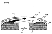
- FIG. 6 shows a rotor structure of an axial gap type rotating electric machine according to the third embodiment.
- the notch 11a is provided on the outer diameter side of the magnet 11, and the protrusion 14a for fitting with the notch 11a is provided on the outer ring 14.
- FIGS. 7 to 9 show an example of an assembling method that makes it possible to assemble all the magnets and realize this embodiment without dividing the outer ring.
- a part of the protrusion 14a provided on the outer peripheral ring 14 is removed (the portion shown in FIG. 14b).
- the width of the protrusion removing portion 14b is configured to be the same as or larger than the width of the magnet 11 on the outer diameter side.
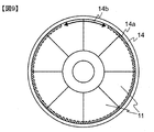
- the magnet 11 is inserted into the protrusion removal portion 14b from the axial direction, and then slid in the circumferential direction with the notch 11a and the protrusion 14a fitted. It is possible to install all the magnets by repeating the same method for all the magnets.
- FIG. 9 shows the structure of the rotor assembled as described above. As shown in the figure, when all the magnets are assembled, by arranging the two magnets 11 in the protrusion removing portion 14b, the protrusions 14a are fitted to all the magnets 11.
- the magnet 11 can be assembled without dividing the outer ring 14. Further, by fitting the notch 11a and the protrusion 14a on the outer diameter side of the magnet 11, it is possible to secure a large area for fitting compared to the structures shown in the first and second embodiments. The holding strength against the tensile force in the axial direction can be improved.
Abstract
Provided is a rotor structure for an axial gap rotary electric machine capable of securing strength for holding a magnet against axial attraction force without causing a reduction in the surface area of the magnet and an increase in the gap length. The present invention provides an axial gap rotary electric machine in which a stator and a rotor are arranged in the direction of the rotation axis with a gap therebetween, wherein a notch is provided on the inner diameter side or outer circumferential side of a magnet disposed in the rotor, and is provided in an intermediate position in the magnet in the axial direction, and a protrusion to be fitted into the notch of the magnet is provided in a yoke that holds the magnet.
Description
本発明は、アキシャルギャップ型回転電機に関し、とくに回転電機の回転子の構造に関する。
The present invention relates to an axial gap type rotating electric machine, and more particularly to a structure of a rotor of the rotating electric machine.
アキシャルギャップ型回転電機は、固定子と、この固定子と所定の空隙(ギャップ)を介して回転軸方向に配置される回転子で構成される。回転子は、周方向に配置された複数の永久磁石と、前記磁石を保持する保持部材で構成される。
An axial gap type rotating electrical machine includes a stator and a rotor arranged in the direction of the rotation axis via the stator and a predetermined gap (gap). The rotor includes a plurality of permanent magnets arranged in the circumferential direction and a holding member that holds the magnets.
アキシャルギャップ型回転電機は、固定子と回転子との対向面積を広くすることで出力を増加させている。加えて、永久磁石の磁力を大きくすることでも出力を増加させることが可能となる。
¡Axial gap type rotating electrical machines increase output by widening the facing area between the stator and the rotor. In addition, the output can be increased by increasing the magnetic force of the permanent magnet.
これに伴い、磁石に働く吸引力(空隙を介して、固定子方向に作用する電磁力)も増加する。例えば、特許文献1に記載のように磁石のギャップ対向面から軸方向にテーパや切欠を設けることで、軸方向(固定子方向)に働く吸引力に対して磁石を保持する方法がある。また、特許文献2に記載のように、磁石の外径側に設けた筒部の一部を内径側に突出させ、ギャップ部分に磁石を保持するための突起を設けることで磁石を保持する方法がある。
Along with this, the attractive force acting on the magnet (electromagnetic force acting in the direction of the stator via the gap) also increases. For example, there is a method of holding a magnet against an attractive force acting in the axial direction (stator direction) by providing a taper or notch in the axial direction from the gap facing surface of the magnet as described in Patent Document 1. Further, as described in Patent Document 2, a method of holding a magnet by projecting a part of a cylindrical portion provided on the outer diameter side of the magnet toward the inner diameter side and providing a protrusion for holding the magnet in the gap portion. There is.
しかしながら、 特許文献1に記載の保持構造では、テーパないしは切欠を設けているため、固定子と対向する磁石の表面積が減少するため、回転電機のトルク低下や効率低下を招くことが課題となる。一方、特許文献2に記載の保持構造では、磁石を保持するためにギャップ部分に突起を設けた構造となっており、突起の厚み分だけギャップ長が増加するために回転電機のトルク低下や効率低下を招くことが課題となる。
However, in the holding structure described in Patent Document 1, since the taper or notch is provided, the surface area of the magnet facing the stator is reduced, which causes a reduction in torque and efficiency of the rotating electrical machine. On the other hand, the holding structure described in Patent Document 2 has a structure in which a protrusion is provided in the gap portion to hold the magnet, and the gap length increases by the thickness of the protrusion. Incurring a decrease is a problem.
本発明は、上記の課題を解決するため、磁石表面積の減少やギャップ長の増加を招くおそれを低減させ、磁石の軸方向吸引力に対する保持強度を確保可能なアキシャルギャップ型回転電機を提供することを目的とする。
In order to solve the above-mentioned problems, the present invention provides an axial gap type rotating electrical machine that can reduce the magnet surface area and increase the gap length, and can secure the holding strength against the axial attractive force of the magnet. With the goal.
上記の目的を達成するために、本発明ではその一例として、回転軸方向に空隙を介して固定子と回転子とが配置されるアキシャルギャップ型回転電機において、前記回転子に配置される磁石の内径側または外周側であって、かつ軸方向の中途に切欠が設けられ、前記磁石を保持するヨークに、前記磁石の切欠と嵌合する突起が設けられていることを特徴とする。
In order to achieve the above object, in the present invention, as an example thereof, in an axial gap type rotating electric machine in which a stator and a rotor are arranged via a gap in the direction of the rotation axis, the magnet arranged on the rotor A notch is provided on the inner diameter side or the outer periphery side and in the middle of the axial direction, and a projection that fits the notch of the magnet is provided on a yoke that holds the magnet.
本発明によれば、磁石表面積の減少やギャップ長の増加を招くおそれを低減させ、モータのトルクや効率の低下を抑制しつつ、軸方向吸引力に対して磁石を保持することが可能となる。
According to the present invention, it is possible to reduce the possibility of causing a decrease in the magnet surface area and an increase in the gap length, and it is possible to hold the magnet against the axial attractive force while suppressing a decrease in the torque and efficiency of the motor. .
以下、本発明の実施例について説明する。図1および図2に本発明を適用する2ロータ型のアキシャルギャップ型回転電機の基本構成を説明するための斜視図を示す。同図に示すように、アキシャルギャップ型回転電機1は,回転軸50方向に一対の円板形状の回転子10を対向するように配置し,一対の回転子10の間に所定のギャップを介して固定子20を挟み込んだ構造を有している。
Hereinafter, examples of the present invention will be described. 1 and 2 are perspective views for explaining the basic configuration of a two-rotor type axial gap rotating electrical machine to which the present invention is applied. As shown in the figure, the axial gap type rotating electrical machine 1 is arranged so that a pair of disk-shaped rotors 10 face each other in the direction of the rotation axis 50, and a predetermined gap is interposed between the pair of rotors 10. Thus, the stator 20 is sandwiched.
<固定子>
固定子20は,周方向に配置される複数のコア22と,各コアの周囲に巻回されるコイル21から構成され、例えば樹脂によるモールドや機械部品(図示省略)によってハウジング40へと保持される。コア21は,渦電流の発生を抑制するために,例えば電磁鋼板やアモルファス箔帯などの磁性薄板の積層体で構成されており,各磁性薄板間は絶縁層で絶縁されている。 <Stator>
Thestator 20 includes a plurality of cores 22 arranged in the circumferential direction and coils 21 wound around the cores, and is held on the housing 40 by, for example, a resin mold or a mechanical part (not shown). The In order to suppress the generation of eddy current, the core 21 is composed of a laminated body of magnetic thin plates such as electromagnetic steel plates and amorphous foil strips, and the magnetic thin plates are insulated by insulating layers.
固定子20は,周方向に配置される複数のコア22と,各コアの周囲に巻回されるコイル21から構成され、例えば樹脂によるモールドや機械部品(図示省略)によってハウジング40へと保持される。コア21は,渦電流の発生を抑制するために,例えば電磁鋼板やアモルファス箔帯などの磁性薄板の積層体で構成されており,各磁性薄板間は絶縁層で絶縁されている。 <Stator>
The
<回転子>
回転子10は,軸方向に凹部を有するヨーク12と,各凹部に配置されるロータコア13を有する。ロータコア13は,例えば接着によってヨーク12の凹部に設置されている。 <Rotor>
Therotor 10 includes a yoke 12 having a recess in the axial direction, and a rotor core 13 disposed in each recess. The rotor core 13 is installed in the concave portion of the yoke 12 by adhesion, for example.
回転子10は,軸方向に凹部を有するヨーク12と,各凹部に配置されるロータコア13を有する。ロータコア13は,例えば接着によってヨーク12の凹部に設置されている。 <Rotor>
The
なお,本発明は上述した2ロータ型のアキシャルギャップ型回転電機に限定されるものではなく、例えば、軸方向に一対の固定子を対向するように配置して、所定のギャップを介して回転子が配置された2ステータ型のアキシャルギャップ型回転電機や、1つの固定子と回転子とが所定のギャップを配置して配置される1ロータ-1ステータ型のアキシャルギャップ型回転電機にも適用可能であることは言うまでもない。
以後,回転子構造に関する実施例を説明する。 The present invention is not limited to the above-described two-rotor axial gap type rotating electrical machine. For example, a pair of stators are arranged so as to face each other in the axial direction, and the rotor is interposed through a predetermined gap. It can also be applied to a two-stator type axial gap type rotating electrical machine in which a stator is arranged and a one-rotor one-stator type axial gap type rotating electrical machine in which one stator and a rotor are arranged with a predetermined gap. Needless to say.
Hereinafter, embodiments relating to the rotor structure will be described.
実施例(1)
図2から図4に実施形態1のアキシャルギャップ型回転電機の回転子構造を示す。同図らに示すように、実施形態1の回転子構造によれば、ヨーク12の内径側に突起12aを設け、かつ、磁石11の内径側に切欠11aを設けている。磁石11は外径側から挿入され、切欠11aが突起12aに嵌合するように配置する。磁石11を周方向に複数配置したのち、磁石11の外径側に外周リング14を設ける。また、磁石11とロータコア13は、磁石の吸引力に加えて、例えば接着剤による接着力によって固定してもよい。 Example (1)
2 to 4 show the rotor structure of the axial gap type rotating electric machine according to the first embodiment. As shown in the drawings, according to the rotor structure of the first embodiment, theprotrusion 12 a is provided on the inner diameter side of the yoke 12, and the notch 11 a is provided on the inner diameter side of the magnet 11. The magnet 11 is inserted from the outer diameter side and arranged so that the notch 11a fits into the protrusion 12a. After arranging a plurality of magnets 11 in the circumferential direction, an outer ring 14 is provided on the outer diameter side of the magnet 11. Further, the magnet 11 and the rotor core 13 may be fixed by an adhesive force of an adhesive, for example, in addition to the attractive force of the magnet.
図2から図4に実施形態1のアキシャルギャップ型回転電機の回転子構造を示す。同図らに示すように、実施形態1の回転子構造によれば、ヨーク12の内径側に突起12aを設け、かつ、磁石11の内径側に切欠11aを設けている。磁石11は外径側から挿入され、切欠11aが突起12aに嵌合するように配置する。磁石11を周方向に複数配置したのち、磁石11の外径側に外周リング14を設ける。また、磁石11とロータコア13は、磁石の吸引力に加えて、例えば接着剤による接着力によって固定してもよい。 Example (1)
2 to 4 show the rotor structure of the axial gap type rotating electric machine according to the first embodiment. As shown in the drawings, according to the rotor structure of the first embodiment, the
以上に示した第1実施例のアキシャルギャップ型回転電機の回転子構造によれば、ヨーク12に設けた突起12aに、磁石11の切欠11aを嵌合しているため、回転電機を駆動した際に磁石が軸方向(ステータ方向)に引っ張られて剥がれ落ちることを防ぐことが可能となる。また、突起12aと切欠11aの嵌合により、軸方向の位置決め精度を高めることも可能となる。さらに、突起12aと切欠11aは、磁石11の回転軸50方向に沿った側面の中途に設けているため、磁石11とコア22との対向面積をより多く確保し、高出力を維持しながら、磁石の軸方向吸引力に対する保持強度を確保することが出来る。
According to the rotor structure of the axial gap type rotating electrical machine of the first embodiment shown above, the notch 11a of the magnet 11 is fitted to the protrusion 12a provided on the yoke 12, so that the rotating electrical machine is driven. It is possible to prevent the magnet from being pulled off in the axial direction (stator direction). Further, the positioning accuracy in the axial direction can be increased by fitting the protrusion 12a and the notch 11a. Furthermore, since the protrusion 12a and the notch 11a are provided in the middle of the side surface along the direction of the rotation axis 50 of the magnet 11, a larger facing area between the magnet 11 and the core 22 is secured, and high output is maintained. The holding strength against the axial attractive force of the magnet can be ensured.
なお、突起12aと切欠11aを設ける位置は、磁石11の回転軸50方向に沿った側面の略中間が、保持強度の観点で望ましいが、本発明はこれに限定されるものではない。
In addition, the position where the protrusion 12a and the notch 11a are provided is preferably approximately in the middle of the side surface along the direction of the rotation axis 50 of the magnet 11 from the viewpoint of holding strength, but the present invention is not limited to this.
また、本実施例では、突起12aを周方向の全周に設けているため、より磁石の軸方向吸引力に対する保持強度を確保することが出来る。なお、本発明は、これに限られず、突起12aを周方向の部分的に設けられても構わない。例えば、図10に示すように、磁石11の分割数に合わせて独立した突起12aを設け、各突起12に対応する切欠11aを設けて突起12aに、磁石11の切欠11aを嵌合させてもよい。これにより、軸方向の位置決め精度を高めることも可能となる。
Further, in this embodiment, since the protrusions 12a are provided on the entire circumference, the holding strength against the axial attractive force of the magnet can be further ensured. In addition, this invention is not restricted to this, You may provide the protrusion 12a partially in the circumferential direction. For example, as illustrated in FIG. 10, independent protrusions 12 a may be provided in accordance with the number of divisions of the magnet 11, the notches 11 a corresponding to the protrusions 12 may be provided, and the notches 11 a of the magnet 11 may be fitted into the protrusions 12 a. Good. Thereby, the positioning accuracy in the axial direction can be increased.
実施例(2)
図5に実施形態2のアキシャルギャップ型回転電機の回転子構造を示す。同図に示すように、実施形態2の回転子構造によれば、実施形態1の構成に加えて、内周側に内周リング15を設ける。また、内周リング15に突起15aを設けて、磁石11に設けた切欠11aを嵌合して配置する。 Example (2)
FIG. 5 shows a rotor structure of the axial gap type rotating electric machine according to the second embodiment. As shown in the figure, according to the rotor structure of the second embodiment, in addition to the configuration of the first embodiment, an innerperipheral ring 15 is provided on the inner peripheral side. Further, a protrusion 15 a is provided on the inner ring 15, and a notch 11 a provided in the magnet 11 is fitted and arranged.
図5に実施形態2のアキシャルギャップ型回転電機の回転子構造を示す。同図に示すように、実施形態2の回転子構造によれば、実施形態1の構成に加えて、内周側に内周リング15を設ける。また、内周リング15に突起15aを設けて、磁石11に設けた切欠11aを嵌合して配置する。 Example (2)
FIG. 5 shows a rotor structure of the axial gap type rotating electric machine according to the second embodiment. As shown in the figure, according to the rotor structure of the second embodiment, in addition to the configuration of the first embodiment, an inner
以上に示した構造によれば、内周リング15および突起15aを別部材で構成することができるため、突起15aを製作する際の製作性が向上する。また、内周リング15および突起15aを別部材で構成しているため、例えば高強度部材を使用することで軸方向への引張力に対する耐強度を向上させることが出来る。また、内周リング15および突起15aを低損失部材にすることで、磁石11の漏れ磁束やコイル21が発生させる磁束が作用することで発生する損失を低減することも可能となる。このように、回転電機の特性に応じて部材の材質を変更することができる利点がある。
According to the structure shown above, since the inner ring 15 and the protrusion 15a can be configured by separate members, the manufacturability when the protrusion 15a is manufactured is improved. In addition, since the inner ring 15 and the protrusion 15a are formed of separate members, for example, by using a high-strength member, it is possible to improve the strength against tensile force in the axial direction. Further, by using the inner ring 15 and the protrusion 15a as a low-loss member, it is possible to reduce the loss caused by the leakage magnetic flux of the magnet 11 or the magnetic flux generated by the coil 21. Thus, there is an advantage that the material of the member can be changed according to the characteristics of the rotating electrical machine.
実施例(3)
図6は実施形態3のアキシャルギャップ型回転電機の回転子構造を示す。同図に示すように、実施形態3の回転子構造によれば、切欠11aを磁石11の外径側に設け、かつ、切欠11aと嵌合するための突起14aを外周リング14に設ける。 Example (3)
FIG. 6 shows a rotor structure of an axial gap type rotating electric machine according to the third embodiment. As shown in the figure, according to the rotor structure of the third embodiment, thenotch 11a is provided on the outer diameter side of the magnet 11, and the protrusion 14a for fitting with the notch 11a is provided on the outer ring 14.
図6は実施形態3のアキシャルギャップ型回転電機の回転子構造を示す。同図に示すように、実施形態3の回転子構造によれば、切欠11aを磁石11の外径側に設け、かつ、切欠11aと嵌合するための突起14aを外周リング14に設ける。 Example (3)
FIG. 6 shows a rotor structure of an axial gap type rotating electric machine according to the third embodiment. As shown in the figure, according to the rotor structure of the third embodiment, the
本実施例では、磁石11の外周側に切欠11aを設けているため、実施形態1および2とは逆に、磁石11を内径側から挿入して組み立てる必要があるが、内径側から挿入して組み立てる場合、最後に挿入する磁石を組み立てることが不可能となる。また、外周リング14を複数に分割することで組み立てることが可能となるが、耐遠心力強度が低下してしまう。そこで、全ての磁石を組み立てることを可能とし、かつ、外周リングを分割することなく本実施例を実現するための組立方法の一例を図7から図9に示す。
In this example, since the notch 11a is provided on the outer peripheral side of the magnet 11, it is necessary to assemble the magnet 11 from the inner diameter side, as opposed to the first and second embodiments. When assembling, it becomes impossible to assemble the magnet to be inserted last. Moreover, although it becomes possible to assemble by dividing | segmenting the outer periphery ring 14 into plurality, centrifugal strength strength will fall. Accordingly, FIGS. 7 to 9 show an example of an assembling method that makes it possible to assemble all the magnets and realize this embodiment without dividing the outer ring.
図7および図8に示すように、外周リング14に設けた突起14aの一部を取り除いている(同図14bで示した箇所)。また、突起除去部14bの幅は、磁石11の外径側の幅と同じか、それよりも大きくなるように構成する。次に、磁石11を軸方向から前述の突起除去部14bに挿入し、その後、切欠11aと突起14aを嵌合した状態で周方向にスライドさせる。全ての磁石について同様の方法をくり返すことで全ての磁石を設置することが可能となる。
7 and 8, a part of the protrusion 14a provided on the outer peripheral ring 14 is removed (the portion shown in FIG. 14b). The width of the protrusion removing portion 14b is configured to be the same as or larger than the width of the magnet 11 on the outer diameter side. Next, the magnet 11 is inserted into the protrusion removal portion 14b from the axial direction, and then slid in the circumferential direction with the notch 11a and the protrusion 14a fitted. It is possible to install all the magnets by repeating the same method for all the magnets.
図9は、上述により組み立てた回転子の構造を示している。同図に示すように、全ての磁石を組み立てた際、突起除去部14bに2つの磁石11が配置されるようにすることで、全ての磁石11に突起14aが嵌合された状態となる。
FIG. 9 shows the structure of the rotor assembled as described above. As shown in the figure, when all the magnets are assembled, by arranging the two magnets 11 in the protrusion removing portion 14b, the protrusions 14a are fitted to all the magnets 11.
以上に示した構造によれば、外周リング14を分割することなく磁石11を組み立てることが可能となる。また、磁石11の外径側で切欠11aと突起14aを嵌合することで、実施形態1および2に示した構造と比較して嵌合する面積を広く確保することが可能となり、磁石11の軸方向への引張力に対する保持強度を向上させることが可能となる。
According to the structure shown above, the magnet 11 can be assembled without dividing the outer ring 14. Further, by fitting the notch 11a and the protrusion 14a on the outer diameter side of the magnet 11, it is possible to secure a large area for fitting compared to the structures shown in the first and second embodiments. The holding strength against the tensile force in the axial direction can be improved.
1:アキシャルギャップ型回転電機
10:回転子
11:磁石
11a:切欠
12:ヨーク
12a:突起
13:ロータコア
14:外周リング
14a:突起
14b:突起除去部
15:内周リング
15a:突起
20:固定子
21:コイル
22:コア
40:ケース(ハウジング)
50:回転軸
60:軸受
70:シャフト 1: axial gap type rotating electrical machine 10: rotor 11:magnet 11a: notch 12: yoke 12a: protrusion 13: rotor core 14: outer ring 14a: protrusion 14b: protrusion removal part 15: inner ring 15a: protrusion 20: stator 21: Coil 22: Core 40: Case (housing)
50: Rotating shaft 60: Bearing 70: Shaft
10:回転子
11:磁石
11a:切欠
12:ヨーク
12a:突起
13:ロータコア
14:外周リング
14a:突起
14b:突起除去部
15:内周リング
15a:突起
20:固定子
21:コイル
22:コア
40:ケース(ハウジング)
50:回転軸
60:軸受
70:シャフト 1: axial gap type rotating electrical machine 10: rotor 11:
50: Rotating shaft 60: Bearing 70: Shaft
Claims (9)
- 回転軸方向に空隙を介して固定子と回転子とが配置されるアキシャルギャップ型回転電機において、
前記回転子に配置される磁石の内径側または外周側であって、かつ軸方向の中途に切欠が設けられ、
前記磁石を保持するヨークに、前記磁石の切欠と嵌合する突起が設けられていることを特徴とするアキシャルギャップ型回転電機。 In the axial gap type rotating electrical machine in which the stator and the rotor are arranged via a gap in the rotation axis direction,
A notch is provided on the inner diameter side or outer periphery side of the magnet disposed in the rotor and in the axial direction,
An axial gap type rotating electrical machine characterized in that a projection that fits into the notch of the magnet is provided on a yoke that holds the magnet. - 請求項1に記載されたアキシャルギャップ型回転電機であって、
前記突起が前記磁石の内径側に配置される内周リングに設けられていることを特徴とするアキシャルギャップ型回転電機。 An axial gap type rotating electrical machine according to claim 1,
An axial gap type rotating electrical machine, wherein the protrusion is provided on an inner ring disposed on the inner diameter side of the magnet. - 請求項1または2に記載されたアキシャルギャップ型回転電機であって、
前記磁石の内径側に設けた前記突起の一部が除去されており、かつ、前記突起の除去部が前記磁石の内径側の周長よりも大きいことを特徴とするアキシャルギャップ型回転電機。 An axial gap type rotating electrical machine according to claim 1 or 2,
An axial gap type rotating electrical machine characterized in that a part of the protrusion provided on the inner diameter side of the magnet is removed, and the removal portion of the protrusion is larger than the circumference on the inner diameter side of the magnet. - 請求項1に記載されたアキシャルギャップ型回転電機であって、
前記突起が前記磁石の外径側に配置される外周リングに設けられていることを特徴とするアキシャルギャップ型回転電機。 An axial gap type rotating electrical machine according to claim 1,
An axial gap type rotating electrical machine, wherein the protrusion is provided on an outer peripheral ring disposed on the outer diameter side of the magnet. - 請求項4に記載されたアキシャルギャップ型回転電機であって、
前記外周リングに設けた突起の一部が除去されており、かつ、前記突起の除去部が前記磁石の外径側の周長よりも大きいことを特徴とするアキシャルギャップ型回転電機。 An axial gap type rotating electrical machine according to claim 4,
An axial gap type rotating electrical machine, wherein a part of the protrusion provided on the outer ring is removed, and a removal portion of the protrusion is larger than a peripheral length on the outer diameter side of the magnet. - 請求項1から5のいずれか1項に記載されたアキシャルギャップ型回転電機であって、
前記磁石は周方向に分割された複数個の分割磁石で構成されることを特徴とするアキシャルギャップ型回転電機。 An axial gap type rotating electrical machine according to any one of claims 1 to 5,
The axial gap type rotating electric machine is characterized in that the magnet is composed of a plurality of divided magnets divided in the circumferential direction. - 請求項1から6のいずれか1項に記載されたアキシャルギャップ型回転電機であって、
前記磁石に設けられた切欠が、前記磁石の軸方向中央部から前記ヨーク側にずれた位置に設けられており、かつ、前記ヨークとの接触面部分に切欠が露出しない位置に設けられていることを特徴とするアキシャルギャップ型回転電機。 An axial gap type rotating electrical machine according to any one of claims 1 to 6,
The notch provided in the magnet is provided at a position shifted from the axial center of the magnet to the yoke side, and is provided at a position where the notch is not exposed at the contact surface portion with the yoke. An axial gap type rotating electrical machine characterized by the above. - 請求項1から6のいずれか1項に記載されたアキシャルギャップ型回転電機であって、
前記磁石に設けられた切欠が、前記磁石の軸方向中央部から前記空隙側にずれた位置に設けられており、かつ、前記空隙部分に切欠が露出しない位置に設けられていることを特徴とするアキシャルギャップ型回転電機。 An axial gap type rotating electrical machine according to any one of claims 1 to 6,
The notch provided in the magnet is provided at a position shifted from the axial center of the magnet toward the gap, and is provided at a position where the notch is not exposed in the gap. Axial gap type rotating electrical machine. - 請求項1から8のいずれか1項に記載されたアキシャルギャップ型回転電機であって、
前記突起及び前記切欠は、前記磁石の軸方向の中央部に設けられていることを特徴とするアキシャルギャップ型回転電機。 An axial gap type rotating electrical machine according to any one of claims 1 to 8,
The axial gap type rotating electrical machine, wherein the protrusion and the notch are provided in a central portion of the magnet in the axial direction.
Applications Claiming Priority (2)
| Application Number | Priority Date | Filing Date | Title |
|---|---|---|---|
| JP2016076266A JP6685166B2 (en) | 2016-04-06 | 2016-04-06 | Axial gap type rotating electric machine |
| JP2016-076266 | 2016-04-06 |
Publications (1)
| Publication Number | Publication Date |
|---|---|
| WO2017175461A1 true WO2017175461A1 (en) | 2017-10-12 |
Family
ID=60000301
Family Applications (1)
| Application Number | Title | Priority Date | Filing Date |
|---|---|---|---|
| PCT/JP2017/003507 WO2017175461A1 (en) | 2016-04-06 | 2017-02-01 | Axial gap rotary electric machine |
Country Status (3)
| Country | Link |
|---|---|
| JP (1) | JP6685166B2 (en) |
| TW (1) | TWI648939B (en) |
| WO (1) | WO2017175461A1 (en) |
Families Citing this family (1)
| Publication number | Priority date | Publication date | Assignee | Title |
|---|---|---|---|---|
| JP7139138B2 (en) * | 2018-04-18 | 2022-09-20 | 株式会社日立産機システム | Axial gap type rotary electric machine |
Citations (2)
| Publication number | Priority date | Publication date | Assignee | Title |
|---|---|---|---|---|
| JPS617275U (en) * | 1984-06-18 | 1986-01-17 | 三洋電機株式会社 | small motor rotor |
| JP2006304592A (en) * | 2005-04-22 | 2006-11-02 | Isa Innovation Sa | System for fixing permanent magnet |
Family Cites Families (4)
| Publication number | Priority date | Publication date | Assignee | Title |
|---|---|---|---|---|
| JP2006014520A (en) * | 2004-06-28 | 2006-01-12 | Toshiba Corp | External rotation type rotor of dynamo-electric machine |
| EP2081276A1 (en) * | 2008-01-21 | 2009-07-22 | Marco Cipriani | Electro-magnetical device with reversible generator-motor operation |
| TWI422437B (en) * | 2008-04-30 | 2014-01-11 | Nidec Copal Corp | Vibration motor |
| WO2015159329A1 (en) * | 2014-04-14 | 2015-10-22 | 株式会社日立産機システム | Axial-air-gap dynamo-electric machine |
-
2016
- 2016-04-06 JP JP2016076266A patent/JP6685166B2/en active Active
-
2017
- 2017-02-01 WO PCT/JP2017/003507 patent/WO2017175461A1/en active Application Filing
- 2017-03-08 TW TW106107593A patent/TWI648939B/en active
Patent Citations (2)
| Publication number | Priority date | Publication date | Assignee | Title |
|---|---|---|---|---|
| JPS617275U (en) * | 1984-06-18 | 1986-01-17 | 三洋電機株式会社 | small motor rotor |
| JP2006304592A (en) * | 2005-04-22 | 2006-11-02 | Isa Innovation Sa | System for fixing permanent magnet |
Also Published As
| Publication number | Publication date |
|---|---|
| TWI648939B (en) | 2019-01-21 |
| JP2017189019A (en) | 2017-10-12 |
| TW201737596A (en) | 2017-10-16 |
| JP6685166B2 (en) | 2020-04-22 |
Similar Documents
| Publication | Publication Date | Title |
|---|---|---|
| JP5958502B2 (en) | Rotor and rotating electric machine using the same | |
| WO2014034344A1 (en) | Rotating electric machine | |
| JP6274475B2 (en) | Rotor, rotating electric machine, and method of manufacturing rotor | |
| US9143014B2 (en) | Rotor, dynamo-electric machine having the rotor and rotor manufacturing method | |
| JP6640621B2 (en) | Motor rotor and brushless motor | |
| US9190878B2 (en) | Rotor including anti-rotation feature for multi-pole structure | |
| JP6055725B2 (en) | Axial type rotating electric machine using rotor and rotor | |
| JP2012120326A (en) | Interior magnet rotor, motor, and method for assembling motor | |
| JP2014045634A (en) | Rotor and rotary electric machine including the same | |
| JP6112970B2 (en) | Permanent magnet rotating electric machine | |
| JP2005333762A (en) | Rotating electric machine and its rotor | |
| WO2017212575A1 (en) | Permanent magnet motor | |
| WO2017175461A1 (en) | Axial gap rotary electric machine | |
| JP2012244808A (en) | Rotor for rotary electric machine | |
| CN112542905A (en) | Axial gap motor | |
| JP2017046386A (en) | Permanent magnet electric motor | |
| JP2010011621A (en) | End plate for rotating electrical machine | |
| JP2015220950A (en) | Rotating electrical machine | |
| JP2014220879A (en) | Permanent magnet rotary electric machine | |
| JP2013031287A (en) | Surface magnet type permanent magnet rotating electric machine | |
| WO2022219923A1 (en) | Rotor and electric motor | |
| JPWO2018131402A1 (en) | Permanent magnet embedded rotor and electric motor equipped with the same | |
| WO2022219942A1 (en) | Rotor and electric motor | |
| JP2009159714A (en) | Electric motor | |
| JP2022011327A (en) | Permanent magnet rotary electric machine and rotor |
Legal Events
| Date | Code | Title | Description |
|---|---|---|---|
| NENP | Non-entry into the national phase |
Ref country code: DE |
|
| 121 | Ep: the epo has been informed by wipo that ep was designated in this application |
Ref document number: 17778840 Country of ref document: EP Kind code of ref document: A1 |
|
| 122 | Ep: pct application non-entry in european phase |
Ref document number: 17778840 Country of ref document: EP Kind code of ref document: A1 |