JP2019062005A - High temperature superconducting coil device and high temperature superconducting magnet device - Google Patents
High temperature superconducting coil device and high temperature superconducting magnet device Download PDFInfo
- Publication number
- JP2019062005A JP2019062005A JP2017183443A JP2017183443A JP2019062005A JP 2019062005 A JP2019062005 A JP 2019062005A JP 2017183443 A JP2017183443 A JP 2017183443A JP 2017183443 A JP2017183443 A JP 2017183443A JP 2019062005 A JP2019062005 A JP 2019062005A
- Authority
- JP
- Japan
- Prior art keywords
- temperature superconducting
- high temperature
- superconducting wire
- wire
- coil device
- Prior art date
- Legal status (The legal status is an assumption and is not a legal conclusion. Google has not performed a legal analysis and makes no representation as to the accuracy of the status listed.)
- Granted
Links
Images


Landscapes
- Superconductors And Manufacturing Methods Therefor (AREA)
Abstract
Description
本発明の実施形態は、テープ状の高温超電導線材を巻回した高温超電導コイル装置及びこれを用いた高温超電導マグネット装置に関する。 The embodiments of the present invention relate to a high temperature superconducting coil device in which a tape-shaped high temperature superconducting wire is wound and a high temperature superconducting magnet device using the same.
超電導線材には、超電導状態を維持できる電流、温度、磁場の範囲、いわゆる臨界電流、臨界温度、臨界磁場が存在する。したがって、電気抵抗がほぼゼロといえども無限に電流が流せるわけではなく、いずれかの臨界値を超えると、常電導状態への転移現象、すなわちクエンチが発生する。 The superconducting wire has a current, a temperature, a range of a magnetic field capable of maintaining a superconducting state, a so-called critical current, a critical temperature, and a critical magnetic field. Therefore, even if the electrical resistance is almost zero, the current can not flow infinitely, and when any one of the critical values is exceeded, a transition to a normal conducting state, ie, quenching occurs.
このようなクエンチによる常電導転移領域のジュール発熱は、瞬時に超電導コイルを熱暴走させ、最悪の場合、焼損に至る危険性がある。そのため、クエンチに対する保護技術が不可欠である。 Such joule heat generation in the normal conduction transition region due to the quenching instantaneously causes thermal runaway of the superconducting coil, and in the worst case, there is a risk of burnout. Therefore, protection techniques against quench are essential.
クエンチ保護に関する従来技術としては、例えば超電導コイルと並列に保護抵抗を接続する方法がある。この方法は、常電導状態に転移することで発生するコイル電圧の上昇又は温度上昇を検出し、この検出結果をトリガーとして励磁電源を遮断する方法である。電源遮断後は、超電導コイルと保護抵抗の閉回路となるため、室温部に配置した保護抵抗のジュール発熱で超電導コイルの蓄積エネルギーが消費され、超電導コイルに流れる電流を減衰させることができる。 As a prior art regarding a quench protection, there exists a method of connecting a protection resistance in parallel with a superconducting coil, for example. This method is a method of detecting a rise in coil voltage or a temperature rise generated by transitioning to a normal conduction state, and using this detection result as a trigger to shut off the excitation power supply. After the power is turned off, a closed circuit of the superconducting coil and the protective resistor is formed, so that the stored energy of the superconducting coil is consumed by Joule heating of the protective resistor disposed at the room temperature portion, and the current flowing in the superconducting coil can be attenuated.
このような超電導コイルに使用する超電導線材としては、例えばBi2Sr2Ca2Cu3O10+x線材や、RE1B2C3O7線材といった高温超電導線材がある。ここで、「RE」は希土類元素であり、「B」はバリウム(Ba)を、「C」は銅(Cu)を、「O」は酸素(O)を意味している。高温超電導線材を用いた超電導コイルでは、従来のNbTi等の低温超電導線材に比べ、20K〜50Kといった高い温度でも高い臨界電流密度を有するため、高温での高電流密度運転が可能となる。
Such superconducting wire used for superconducting coils, for example, Bi 2 Sr 2 Ca 2 Cu 3
しかしながら、高電流密度運転時にクエンチが生じた場合、20K〜50Kの温度範囲では、低温超電導線材を使った超電導マグネットの運転温度よりも比熱が大きいため、常電導転移領域の拡大が遅い。また、高電流密度運転を行うと発熱密度も高くなるため、上記従来技術のクエンチ保護方法では、検知する前に局所的に熱暴走が発生し焼損してしまう。 However, when quenching occurs during high current density operation, the expansion of the normal conduction transition region is slow in the temperature range of 20 K to 50 K because the specific heat is larger than the operating temperature of the superconducting magnet using a low temperature superconducting wire. In addition, since the heat generation density also increases when the high current density operation is performed, in the above-described quench protection method of the prior art, thermal runaway occurs locally before detection and burnout occurs.
そこで、例えば特許文献1では、高温超電導コイル内部において、経験磁場が厳しく臨界電流が低い巻線部に高温超電導線材を貼り合せて部分的に2枚重ねにする技術が提案されている。この技術によれば、通常クエンチする電流値、もしくは温度に達しても、貼り合せた高温超電導線材へ電流を転流することができる。そのため、1枚あたりの高温超電導線材の電流分担は約半分となり、ジュール発熱が抑制されることで、熱暴走を未然に防止することができる。また、部分的に貼り合せることで、電流密度の低下を最低限に留めることができる。
Therefore, for example,
ところで、上記特許文献1では、高温超電導線材を貼り合せる接合方法として、例えば100mmのラップ長で0.01μΩレベルの接続方法が提案されており、通常、本オーダーの抵抗の接続方法としてはハンダ接続がある。その他の接合方法としては、拡散接合、溶接、超音波接合等による接続方法がある。
By the way, in the said
しかしながら、図10に示すように接続した2枚重ねの高温超電導線材1,2は、接合層3を介して一体化されているため、コイル化した際の曲げ歪ε=(t´/2)/Rが、1枚の場合の2倍となる。ここで、Rは平均曲率半径を示し、t´は、接合層3の厚さを含めた2枚の高温超電導線材1,2の厚さの和t´=t1+t2+t3を示す。また、t1、t2は、2枚の高温超電導線材1,2の厚さを示し、t3は、接合層3の厚さを示している。
However, since the two high temperature
さらに、上記2枚重ねの高温超電導線材1,2は、線材厚さ方向の剛性が高くなるため、巻線時、均一な曲率で円形の巻線部に巻き取ることが困難になる。したがって、不均一な曲率で曲げると、局所的に許容曲げ歪を超えてしまい、高温超電導線材1,2の臨界電流特性が1枚あるいは2枚とも劣化する。その結果、当初目的とした電流の転流による熱暴走を防止することができなくなるばかりか、劣化箇所のジュール発熱で熱暴走し焼損してしまう可能性があった。
Furthermore, since the high-temperature
本実施形態が解決しようとする課題は、高温超電導線材の臨界電流特性を劣化させることなく、内部における局所的な熱暴走を未然に防止可能な高温超電導コイル装置及び高温超電導マグネット装置を提供することにある。 The problem to be solved by the present embodiment is to provide a high temperature superconducting coil device and a high temperature superconducting magnet device capable of preventing local thermal runaway inside without deteriorating the critical current characteristics of the high temperature superconducting wire. It is in.
上記課題を解決するために、本実施形態に係る高温超電導コイル装置は、テープ状の高温超電導線材を巻回した高温超電導コイル装置であって、少なくとも1ターンを超える巻線部の少なくとも1箇所において、前記高温超電導線材が複数巻回され、これら複数の高温超電導線材が直接接触にて電気的に接続されていることを特徴とする。 In order to solve the above problems, the high temperature superconducting coil device according to the present embodiment is a high temperature superconducting coil device in which a tape-shaped high temperature superconducting wire is wound, and at least one place of a winding portion exceeding at least one turn. A plurality of the high temperature superconducting wires are wound, and the plurality of high temperature superconducting wires are electrically connected by direct contact.
本実施形態に係る高温超電導マグネット装置は、本実施形態に係る高温超電導コイル装置を備えていることを特徴とする。 The high temperature superconducting magnet apparatus according to the present embodiment is characterized by including the high temperature superconducting coil apparatus according to the present embodiment.
本実施形態によれば、高温超電導線材の臨界電流特性を劣化させることなく、高温超電導コイル装置内部における局所的な熱暴走を未然に防止することが可能になる。 According to this embodiment, it is possible to prevent local thermal runaway inside the high temperature superconducting coil device without deteriorating the critical current characteristics of the high temperature superconducting wire.
以下、本実施形態に係る高温超電導コイル装置及び高温超電導マグネット装置について、図面を参照して説明する。 Hereinafter, the high temperature superconducting coil device and the high temperature superconducting magnet device according to the present embodiment will be described with reference to the drawings.
(高温超電導線材)
図1は各実施形態の高温超電導コイル装置に用いられる高温超電導線材(超電導テープ線)の一例を示す構成図である。
(High temperature superconducting wire)
FIG. 1: is a block diagram which shows an example of the high temperature superconducting wire (superconducting tape wire) used for the high temperature superconducting coil apparatus of each embodiment.
なお、従来例と同一又は対応する部分には、同一の符号を付して説明する。また、以下の説明において、第1の高温超電導線材と第2の高温超電導線材を区別して説明する場合には、それぞれ符号1,2を付して説明する。また、第1の高温超電導線材と第2の高温超電導線材をまとめて説明する場合には、単に符号1だけを付して説明する。
The same or corresponding parts as in the conventional example will be described with the same reference numerals. In the following description, when the first high-temperature superconducting wire and the second high-temperature superconducting wire are described separately, they are denoted by
図1に示すように、高温超電導線材1は、全体がテープ状に形成されている。高温超電導線材1は、少なくともテープ基板4と、中間層5と、超電導層6とを有し、その両面が安定化層7で被覆されている。
As shown in FIG. 1, the high-temperature
高温超電導線材1は、必要に応じて、テープ基板4と中間層5との間に配向層8を、超電導層6と安定化層7との間に保護層9を、それぞれ設けることもできる。
The high temperature
テープ基板4は、例えばステンレス鋼、ハステロイ等のニッケル合金、銀合金等の材質で形成される。 The tape substrate 4 is formed of, for example, a material such as stainless steel, a nickel alloy such as hastelloy, or a silver alloy.
中間層5は、拡散防止層であり、例えば、酸化セリウム、イットリア安定化ジルコニア(YSZ)、酸化マグネシウム、酸化イットリウム、酸化イッテルビウム、バリウムジルコニア等の材質からなり、テープ基板4上に形成される。 The intermediate layer 5 is a diffusion preventing layer and made of, for example, materials such as cerium oxide, yttria-stabilized zirconia (YSZ), magnesium oxide, yttrium oxide, ytterbium oxide, barium zirconia and the like, and is formed on the tape substrate 4.
超電導層6は、例えば、RE123系の組成(RE1B2C3O7等)を有する超電導体薄膜からなる。なお、「RE1B2C3O7」の「RE」は希土類元素(例えば、ネオジム(Nd)、ガドリニウム(Gd)、ホルミニウム(Ho)、サマリウム(Sm)等)及びイットリウム元素の少なくともいずれかを、「B」はバリウム(Ba)を、「C」は銅(Cu)を、「O」は酸素(O)を意味している。 The superconducting layer 6 is made of, for example, a superconductor thin film having a composition of RE123 system (RE 1 B 2 C 3 O 7 or the like). In addition, "RE" of "RE 1 B 2 C 3 O 7 " is at least one of rare earth elements (eg, neodymium (Nd), gadolinium (Gd), holmium (Ho), samarium (Sm), etc.) and yttrium element. “B” means barium (Ba), “C” means copper (Cu) and “O” means oxygen (O).
安定化層7は、超電導層6に過剰に電気が流れた場合に超電導層6が燃焼するのを防止する目的で設けられ、導電性の高い銀等から形成される。
The
配向層8は、テープ基板4上に中間層5を配向させて形成する目的で設けられ、酸化マグネシウム(MgO)等から形成される。なお、配向層8は、配向した基板を用いる場合には省略することができる。
The
保護層9は、超電導層6が空気中の水分に触れて劣化するのを防止する等の目的で設けられ、銀等から形成される。なお、保護層9も超電導層6に過剰に電気が流れた場合に超電導層6が燃焼するのを防止する役割も果たす。 The protective layer 9 is provided for the purpose of preventing the superconducting layer 6 from deteriorating due to contact with moisture in the air, and is made of silver or the like. The protective layer 9 also plays a role of preventing the superconducting layer 6 from burning when electricity flows excessively to the superconducting layer 6.
このような多層からなる高温超電導線材1のテープ幅wは、例えば4〜12mm、テープ厚さtは0.1〜0.2mmとされる。また、高温超電導線材1は、長手方向の機械強度に優れている半面、テープ面垂直方向の引張応力(剥離応力)には脆弱であるという特徴を備える。
The tape width w of the high temperature
また、さらに高温超電導線材1の周囲をポリイミドやポリイミドアミドのような絶縁材で被覆した絶縁被覆超電導テープ線としてもよい。
Furthermore, an insulation coated superconducting tape wire may be used in which the high temperature
(高温超電導コイル装置)
図2(a)は各実施形態の高温超電導コイル装置の一例のパンケーキコイルを示す概略斜視図、図2(b)は図2(a)の概略断面図、図2(c)は図2(b)の拡大断面図である。
(High temperature superconducting coil device)
Fig.2 (a) is a schematic perspective view which shows the pancake coil of an example of the high temperature superconducting coil apparatus of each embodiment, FIG.2 (b) is a schematic sectional drawing of Fig.2 (a), FIG.2 (c) is FIG. It is an expanded sectional view of (b).
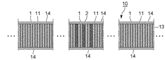
図2(b),(c)に示すように、高温超電導線材1は、絶縁テープ線11と重ね合わせ、ガラス繊維強化プラスチック(FRP)や補強型PTFE(ポリテトラフルオロエチレン)等の絶縁材からなる巻枠12の周囲に渦巻状に巻回された、いわゆるパンケーキ形状の巻線部13が形成される。また、必要に応じて巻線部13の上下両面に絶縁層14を形成することで、図2(a)に示すようないわゆるパンケーキ形状の高温超電導コイル装置10、すなわちパンケーキコイルが形成される。
As shown in FIGS. 2 (b) and 2 (c), the high
(第1実施形態)
(構 成)
図3は第1実施形態の高温超電導コイル装置を示す断面図である。図4は第1実施形態において巻取り直後の高温超電導線材をコイル上面から見た図である。図5は第1実施形態において共巻きされる巻線部のターン数と単位長さあたりの電圧との関係を示すグラフである。
First Embodiment
(Constitution)
FIG. 3 is a cross-sectional view showing the high-temperature superconducting coil device of the first embodiment. FIG. 4 is a view of the high-temperature superconducting wire immediately after winding in the first embodiment as viewed from the top of the coil. FIG. 5 is a graph showing the relationship between the number of turns of the winding part to be co-wound and the voltage per unit length in the first embodiment.
本実施形態の高温超電導コイル装置10は、図3に示すように巻枠12の外周に巻回された第1の高温超電導線材1は、少なくとも1ターンを超える巻線部13において、第1の高温超電導線材1に隣接して第2の高温超電導線材2が共巻きされている。第1の高温超電導線材1と第2の高温超電導線材2とは、従来のようにハンダ等の接合層を介して固着されておらず、直接接触により電気的に接続されて構成されている。第2の高温超電導線材2は、高温超電導線材1の多層構造、テープ幅w、及び厚さtと同一のものである。
In the high temperature
ここで、共巻きされる少なくとも1ターンを超える巻線部13は、クエンチ保護の設計に応じて、少なくとも1箇所に設ければよく、本実施形態では、例えば全ターン数が100ターンのコイルにおいて、10から30ターンと、90から100ターンの2箇所に共巻きされている。
Here, the
なお、第1の高温超電導線材1と第2の高温超電導線材2との間の直接接触による単位長さあたりの電気的な接続の抵抗Rjointは、励磁電源のリップル電流がおおよそ0.1〜数%である。これにより、転流の効果を得るためには、第1の高温超電導線材1に対する第2の高温超電導線材2への転流比を、少なくとも1/1000以上にしておく必要がある。
The resistance R joint of the electrical connection per unit length by the direct contact between the first high
一方、クエンチする前後で高温超電導線材1,2に発生する単位長さあたりの電圧は、1μV/cm程度であるから、抵抗値は1μV/cmを運転電流値で割って算出される値となる。
On the other hand, since the voltage per unit length generated in the high
したがって、第1の高温超電導線材1と第2の高温超電導線材2との間の直接接触による単位長さあたりの電気的な接続の抵抗Rjointを、単位長さあたりの電圧1μV/cmを運転電流値で割って算出される抵抗値の1000倍以下とすることが好ましい。
Therefore, the resistance R joint of electrical connection per unit length by direct contact between the first high
一例として、運転電流値が100Aの場合には、クエンチする前後で高温超電導線材1,2に発生する単位長さあたりの抵抗値が10−8Ω/cmとなることから、第1の高温超電導線材1と第2の高温超電導線材2との間の直接接触による単位長さあたりの電気的な接続の抵抗Rjointは、10−5Ω/cm以下に設定すればよい。
As an example, when the operating current value is 100 A, the resistance value per unit length generated in the high
また、第2の高温超電導線材2は、第1の高温超電導線材1と同様に、RE1B2C3O7を超電導層とした高温超電導線材以外に、(Bi,Pb)2Ca2Sr1Cu2O10+x、(Bi,Pb)2Ca2Sr2Cu3O10+x、(Bi,Pb)2Ca2Sr3Cu4O10+x等の組成のいわゆるビスマス系高温超電導材料を用いた超電導テープであってもよい。
Further, the second high
このようなビスマス系の超電導テープは、銀の母材にフィラメント状のビスマス系高温超電導材料が複数注入された、いわゆる多芯テープ線材であり、設計に応じては補強用に高強度の金属テープが付属される。 Such a bismuth-based superconducting tape is a so-called multicore tape wire material in which a plurality of filamentous bismuth-based high-temperature superconducting materials are injected into a silver base material, and depending on the design, a high-strength metal tape for reinforcement. Is attached.
(作 用)
上述したように、従来例において、2枚重ねの高温超電導線材1,2は、ハンダ等の接合層3により一体化されているため、厚みが1枚の場合の2倍となり、コイル化した際の曲げ歪も、1枚の場合の2倍となる。そして、線材厚さ方向の剛性が高くなるため、巻線時、均一な曲率で円形の巻線部13に巻き取ることが困難になる。したがって、不均一な曲率で曲げてしまうと、局所的に許容曲げ歪を超えてしまい、高温超電導線材1,2の臨界電流特性が1枚あるいは2枚とも劣化する。その結果、当初目的とした電流の転流による熱暴走の防止ができなくなるばかりか、劣化箇所のジュール発熱で熱暴走し焼損してしまう可能性がある。
(Operation)
As described above, in the conventional example, since the two high
これに対し、本実施形態において、第1の高温超電導線材1と第2の高温超電導線材2とは、ハンダ等の接合層3により一体化されておらず、直接接触により電気的に接続されている。そのため、第2の高温超電導線材2は、巻線時、図4に示す矢印の方向に摺動可能となる。
On the other hand, in the present embodiment, the first high
そのため、本実施形態では、第2の高温超電導線材2は、第1の高温超電導線材1と同じく、1枚分の曲げ歪ε=(t2/2)/Rで曲げることができる。また、巻線時、第1の高温超電導線材1と同じく、均一な曲率で円形の巻線部13に巻き取ることができるため、第1の高温超電導線材1と第2の高温超電導線材2の臨界電流特性を劣化させることがなくなる。そして、第1の高温超電導線材1がクエンチした際、第2の高温超電導線材2への電流の転流が可能となり、ジュール発熱が抑制される効果で、高温超電導コイル装置10内部における局所的な熱暴走を未然に防止することが可能となる。
Therefore, in this embodiment, the second high-
具体的に、本実施形態では、例えば全ターン数(全巻数N)が100ターンのコイルにおいて、第1の高温超電導線材1の10から30ターンと、90から100ターンの2箇所に第2の高温超電導線材2が共巻きされている。図5に示すように第1の高温超電導線材1がクエンチした際、10から30ターンと、90から100ターンの2箇所においては、第1の高温超電導線材1に発生する単位長さあたりの電圧V(V/cm)が実線で示す波形から波線で示す波形になる。これは、第1の高温超電導線材1がクエンチした際、第2の高温超電導線材2へ電流が確実に転流することで、単位長さあたりの電圧Vが低下していることを表している。
Specifically, in the present embodiment, for example, in a coil having a total number of turns (total number of turns N) of 100 turns, the second high
(効 果)
このように本実施形態によれば、第1の高温超電導線材1と第2の高温超電導線材2とは、直接接触により電気的に接続されているため、第1の高温超電導線材1と第2の高温超電導線材2の臨界電流特性の臨界電流特性を劣化させることなく、高温超電導コイル装置10内部における局所的な熱暴走を未然に防止することが可能になる。
(Effect)
As described above, according to the present embodiment, since the first high
なお、本実施形態では、高温超電導コイル装置10として、同心円状に巻回してなる、いわゆるパンケーキ形状のパンケーキコイルの例を示したが、これに限らずパンケーキコイルを中心軸方向に2つ積層し、かつ最内周では高温超電導線材が軸方向に転移する、いわゆるダブルパンケーキ方式の高温超電導コイル装置にも適用可能である。また、パンケーキコイル10を中心軸方向に3つ以上積層するように構成してもよい。さらに、コイルの平面形状は、円形に限らず、D形状や楕円形状、レーストラック形状、3次元形状等の非円形のコイル形状でも同様の効果を得ることができる。
In the present embodiment, an example of a pancake coil of a so-called pancake shape, which is wound concentrically as the high temperature
(第2実施形態)
(構 成)
図6は第2実施形態において第1と第2の高温超電導線材が共巻きされている部分を示す拡大断面図である。なお、第2実施形態は、前記第1実施形態の変形例である。第2実施形態は、前記第1実施形態と同一又は対応する部分には、同一の符号を付して重複する説明は省略し、異なる構成及び作用のみを説明する。その他の実施形態も同様とする。
Second Embodiment
(Constitution)
FIG. 6 is an enlarged sectional view showing a portion where the first and second high temperature superconducting wires are co-wound in the second embodiment. The second embodiment is a modification of the first embodiment. In the second embodiment, the same or corresponding parts as in the first embodiment are given the same reference numerals, and redundant explanations will be omitted, and only different configurations and actions will be described. The same applies to the other embodiments.
図6に示すように、本実施形態の高温超電導コイル装置10は、第1の高温超電導線材1の超電導層15と第2の高温超電導線材2の超電導層16が片側に寄って設けられている。
As shown in FIG. 6, in the high temperature
そして、本実施形態の高温超電導コイル装置10は、第1の高温超電導線材1の超電導層15に近い側のテープ面と、第2の高温超電導線材2の超電導層16に近い側のテープ面とが隣接して構成されている。
The high temperature
(作 用)
このように構成された本実施形態において、第1の高温超電導線材1と第2の高温超電導線材2とは、超電導層15,16に近い側のテープ面同士が隣接して配置されている。そのため、両方の高温超電導線材1,2がテープ基板4に近い側のテープ面を向いている場合と比較して、電気的な接続の抵抗をより低くすることができる。
(Operation)
In the embodiment configured as described above, the first high
(効 果)
このように本実施形態によれば、第1の高温超電導線材1と第2の高温超電導線材2との電気的な接続の抵抗をより低くすることができるため、第1の高温超電導線材1がクエンチした際、第2の高温超電導線材2への電流の転流が容易となり、前記第1実施形態と比較して、より確実に高温超電導コイル装置10内部における局所的な熱暴走を未然に防止することが可能になる。
(Effect)
As described above, according to the present embodiment, since the resistance of the electrical connection between the first high
(第3実施形態)
(構 成)
図7は第3実施形態の高温超電導コイル装置を示す断面図である。
Third Embodiment
(Constitution)
FIG. 7 is a cross-sectional view showing the high-temperature superconducting coil device of the third embodiment.
図7に示すように、本実施形態の高温超電導コイル装置10は、第2の高温超電導線材2に隣接して、テープ状の金属線材17が直接接触により電気的に接続されて構成されている。金属線材17の材質としては、銅や金、銀、インジウム等の純金属や、ステンレス鋼や銅合金、銀合金等の合金を用いることができる。
As shown in FIG. 7, the high temperature
(作 用)
このように構成された本実施形態において、第2の高温超電導線材2に隣接して、テープ状の金属線材17が直接接触により電気的に接続されているため、第1の高温超電導線材1がクエンチした際、電流が転流可能な領域が拡大するとともに、1ターン分の巻線部13の熱容量が増加するため、ジュール発熱による温度上昇を抑制することができる。
(Operation)
In the embodiment configured as described above, since the tape-shaped
(効 果)
このように本実施形態によれば、第1の高温超電導線材1がクエンチした際、電流が転流可能な領域が拡大するとともに、1ターン分の巻線部13の熱容量が増加するため、ジュール発熱による温度上昇を抑制することができるため、第1実施形態及び第2実施形態よりも、さらに確実に高温超電導コイル装置10内部における局所的な熱暴走を未然に防止することが可能になる。
(Effect)
As described above, according to the present embodiment, when the first high
(変形例)
なお、本実施形態の高温超電導コイル装置10は、テープ状の金属線材17が第2の高温超電導線材2に直接接触により電気的に接続されているが、この金属線材17は、第1の高温超電導線材1に直接接触により電気的に接続するようにしてもよい。また、金属線材17は、第2の高温超電導線材2及び第1の高温超電導線材1の双方に直接接触により電気的に接続するようにしてもよい。要するに、金属線材17は、第2の高温超電導線材2及び第1の高温超電導線材1の少なくとも一方に直接接触により電気的に接続させればよい。
(Modification)
In the high temperature
(第4実施形態)
(構 成)
図8は第4実施形態の高温超電導コイル装置を示す断面図である。
Fourth Embodiment
(Constitution)
FIG. 8 is a cross-sectional view showing the high-temperature superconducting coil device of the fourth embodiment.
図8に示すように、本実施形態の高温超電導コイル装置10は、第2の高温超電導線材2が、前記第1実施形態乃至第3実施形態に記載の第2の高温超電導線材2よりもテープ厚さが薄く形成されている。
As shown in FIG. 8, in the high temperature
すなわち、前記第1実施形態乃至第3実施形態に記載の第2の高温超電導線材2は、第1の高温超電導線材1とテープ厚さが同じであるが、本実施形態の第2の高温超電導線材2は、第1の高温超電導線材1よりもテープ厚さが薄く形成されている。
That is, although the second high-
例えば、前記第1実施形態乃至第3実施形態に記載の第1の高温超電導線材1と第2の高温超電導線材2のテープ厚さが0.17mmとすると、本実施形態の第2の高温超電導線材2のテープ厚さが0.1mmである。
For example, assuming that the tape thickness of the first high-
(作 用)
このように構成された本実施形態において、第2の高温超電導線材2のテープ厚さを第1の高温超電導線材1よりも薄く形成したので、前記第1実施形態乃至第3実施形態に比べて1ターンの巻線部13の熱容量は減少するものの、巻線部13の断面積をより小さくすることができる。
(Operation)
In this embodiment configured as described above, the tape thickness of the second high
(効 果)
このように本実施形態によれば、前記第1実施形態乃至第3実施形態に比べて1ターンの巻線部13の熱容量は減少するものの、巻線部13の断面積をより小さくすることができるため、共巻きの影響による電流密度の低下を抑えることができる。
(Effect)
As described above, according to the present embodiment, although the heat capacity of the winding
(変形例)
なお、本実施形態の第2の高温超電導線材2は、前記第1実施形態乃至第3実施形態に記載の第1の高温超電導線材1と第2の高温超電導線材2よりもテープ厚さtを薄く形成したが、これに限らず第2の高温超電導線材2を前記第1実施形態乃至第3実施形態に記載の第2の高温超電導線材2よりもテープ幅wを狭く形成してもよい。このように第1の高温超電導線材1と第2の高温超電導線材2は、テープ厚さt又はテープ幅wが必ずしも同じでなくてもよい。
(Modification)
The second high-
(高温超電導マグネット装置)
図9は各実施形態の高温超電導コイル装置を適用した高温超電導マグネット装置の一例を示す縦断面図である。
(High temperature superconducting magnet device)
FIG. 9 is a longitudinal sectional view showing an example of a high temperature superconducting magnet device to which the high temperature superconducting coil device of each embodiment is applied.
図9に示すように、高温超電導マグネット装置20は、真空容器21内に上述した各実施形態のいずれかの高温超電導コイル装置10が収納されている。この高温超電導コイル装置10は、図示しない支持部材によって支持されている。
As shown in FIG. 9, in the high-temperature
冷凍機22は、真空容器21内で伝熱板23を介して高温超電導コイル装置10と熱的に接続されている。真空容器21の外側には、2つの電流導入端子24,24が設けられている。これら2つの電流導入端子24,24のそれぞれに電流リード25,25の一端が接続され、これら電流リード25,25の他端が高温超電導コイル装置10に接続されている。電流リード25,25は、冷凍機22の冷却端と熱アンカー26を介して熱的に接続されている。
The
したがって、このように構成された高温超電導マグネット装置20に各実施形態の高温超電導コイル装置10を収納することで、高温超電導コイル装置10内部の熱暴走を未然に防止することができる。
Therefore, thermal runaway inside high temperature
(その他の実施形態)
本発明の実施形態を説明したが、この実施形態は、例として提示したものであり、発明の範囲を限定することは意図していない。この実施形態は、その他の様々な形態で実施されることが可能であり、発明の要旨を逸脱しない範囲で、種々の省略、置き換え、変更、組み合わせを行うことができる。この実施形態やその変形は、発明の範囲や要旨に含まれると同様に、特許請求の範囲に記載された発明とその均等の範囲に含まれるものである。
(Other embodiments)
Although the embodiments of the present invention have been described, this embodiment is presented as an example and is not intended to limit the scope of the invention. This embodiment can be implemented in other various forms, and various omissions, replacements, changes, and combinations can be made without departing from the scope of the invention. This embodiment and its modifications are included in the invention described in the claims and the equivalents thereof as well as included in the scope and the gist of the invention.
なお、上記各実施形態の高温超電導コイル装置10では、2つの高温超電導線材、すなわち第1の高温超電導線材1と第2の高温超電導線材2を共巻きした例について説明したが、これに限らず例えばテープ状の高温超電導線材を3つ以上直接接触にて電気的に接続するようにしてもよい。
In the high temperature
また、上記第1実施形態の高温超電導コイル装置10では、巻線部13の2箇所において2つの高温超電導線材1,2を共巻きした例について説明したが、これに限らず巻線部13の少なくとも1箇所において2つの高温超電導線材1,2を共巻きするようにしてもよい。
In the high temperature
さらに、上記各実施形態の高温超電導コイル装置10の特徴を組み合わせて実施することもできる。
Furthermore, the features of the high temperature
1…第1の高温超電導線材、2…第2の高温超電導線材、3…接合層、4…テープ基板、5…中間層、6…超電導層、7…安定化層、8…配向層、9…保護層、10…高温超電導コイル装置(パンケーキコイル)、11…絶縁テープ線、12…巻枠、13…巻線部、14…絶縁層、15,16…超電導層、17…金属線材、20…高温超電導マグネット装置、21…真空容器、22…冷凍機、23…伝熱板、24…電流導入端子、25…電流リード、26…熱アンカー
DESCRIPTION OF
Claims (9)
少なくとも1ターンを超える巻線部の少なくとも1箇所において、前記高温超電導線材が複数巻回され、これら複数の高温超電導線材が直接接触にて電気的に接続されていることを特徴とする高温超電導コイル装置。 A high temperature superconducting coil device in which a tape-shaped high temperature superconducting wire is wound,
A high temperature superconducting coil characterized in that a plurality of the high temperature superconducting wires are wound in at least one place of a winding part exceeding at least one turn, and the plurality of high temperature superconducting wires are electrically connected in direct contact. apparatus.
Priority Applications (1)
| Application Number | Priority Date | Filing Date | Title |
|---|---|---|---|
| JP2017183443A JP6871117B2 (en) | 2017-09-25 | 2017-09-25 | High-temperature superconducting coil device and high-temperature superconducting magnet device |
Applications Claiming Priority (1)
| Application Number | Priority Date | Filing Date | Title |
|---|---|---|---|
| JP2017183443A JP6871117B2 (en) | 2017-09-25 | 2017-09-25 | High-temperature superconducting coil device and high-temperature superconducting magnet device |
Publications (2)
| Publication Number | Publication Date |
|---|---|
| JP2019062005A true JP2019062005A (en) | 2019-04-18 |
| JP6871117B2 JP6871117B2 (en) | 2021-05-12 |
Family
ID=66177569
Family Applications (1)
| Application Number | Title | Priority Date | Filing Date |
|---|---|---|---|
| JP2017183443A Active JP6871117B2 (en) | 2017-09-25 | 2017-09-25 | High-temperature superconducting coil device and high-temperature superconducting magnet device |
Country Status (1)
| Country | Link |
|---|---|
| JP (1) | JP6871117B2 (en) |
Cited By (1)
| Publication number | Priority date | Publication date | Assignee | Title |
|---|---|---|---|---|
| JP7438830B2 (en) | 2020-04-10 | 2024-02-27 | 株式会社東芝 | Bundle-wound high-temperature superconducting coil device |
Citations (3)
| Publication number | Priority date | Publication date | Assignee | Title |
|---|---|---|---|---|
| JP2005510843A (en) * | 2001-11-28 | 2005-04-21 | アメリカン スーパーコンダクター コーポレイション | Superconductor cables and magnetic devices |
| JP2015179764A (en) * | 2014-03-19 | 2015-10-08 | 株式会社東芝 | High-temperature superconducting magnet device and high-temperature superconducting magnet demagnetizing method |
| JP2017068931A (en) * | 2015-09-28 | 2017-04-06 | 株式会社東芝 | High-temperature superconductor, high-temperature superconducting coil, and high-temperature superconducting coil connection structure |
-
2017
- 2017-09-25 JP JP2017183443A patent/JP6871117B2/en active Active
Patent Citations (3)
| Publication number | Priority date | Publication date | Assignee | Title |
|---|---|---|---|---|
| JP2005510843A (en) * | 2001-11-28 | 2005-04-21 | アメリカン スーパーコンダクター コーポレイション | Superconductor cables and magnetic devices |
| JP2015179764A (en) * | 2014-03-19 | 2015-10-08 | 株式会社東芝 | High-temperature superconducting magnet device and high-temperature superconducting magnet demagnetizing method |
| JP2017068931A (en) * | 2015-09-28 | 2017-04-06 | 株式会社東芝 | High-temperature superconductor, high-temperature superconducting coil, and high-temperature superconducting coil connection structure |
Cited By (1)
| Publication number | Priority date | Publication date | Assignee | Title |
|---|---|---|---|---|
| JP7438830B2 (en) | 2020-04-10 | 2024-02-27 | 株式会社東芝 | Bundle-wound high-temperature superconducting coil device |
Also Published As
| Publication number | Publication date |
|---|---|
| JP6871117B2 (en) | 2021-05-12 |
Similar Documents
| Publication | Publication Date | Title |
|---|---|---|
| JP5823116B2 (en) | Superconducting coil | |
| JP5259487B2 (en) | Superconducting coil | |
| JP4743150B2 (en) | Superconducting coil and superconducting conductor used therefor | |
| JP6666274B2 (en) | High temperature superconducting permanent current switch and high temperature superconducting magnet device | |
| JPWO2017061563A1 (en) | Superconducting coil | |
| WO2017057064A1 (en) | High-temperature superconducting conductor, high-temperature superconducting coil, and connecting structure of high-temperature superconducting coil | |
| ES2938711T3 (en) | High Temperature Superconducting Magnet | |
| JP5879749B2 (en) | Superconducting coil, superconducting magnet, and manufacturing method of superconducting coil | |
| JP5022279B2 (en) | Oxide superconducting current lead | |
| JP2012256744A (en) | Superconductive coil | |
| JP6548916B2 (en) | High temperature superconducting coil | |
| JP2014154320A (en) | Connection structure of oxide superconductive wire rod and superconductive apparatus | |
| JP6738720B2 (en) | Superconducting wire connection structure | |
| JP6871117B2 (en) | High-temperature superconducting coil device and high-temperature superconducting magnet device | |
| JP7210411B2 (en) | Superconducting coil device | |
| JP6035050B2 (en) | Superconducting coil device and manufacturing method thereof | |
| JP5728365B2 (en) | Oxide superconducting coil, superconducting equipment, and oxide superconducting coil manufacturing method | |
| JP2020136637A (en) | High-temperature superconducting magnet device | |
| JP2017204333A (en) | Superconductive tape wire, superconductive current lead using superconductive tape, permanent current switch, and superconductive coil | |
| JP6005428B2 (en) | Superconducting coil and superconducting coil device | |
| JP2009230912A (en) | Oxide superconductive current lead | |
| JP7222622B2 (en) | Superconducting coil and superconducting coil device | |
| JP4634954B2 (en) | Superconducting device | |
| JP2015035308A (en) | Connection structure of oxide superconductive wire and superconductive apparatus provided with the same | |
| JP7438830B2 (en) | Bundle-wound high-temperature superconducting coil device |
Legal Events
| Date | Code | Title | Description |
|---|---|---|---|
| A711 | Notification of change in applicant |
Free format text: JAPANESE INTERMEDIATE CODE: A712 Effective date: 20171201 Free format text: JAPANESE INTERMEDIATE CODE: A711 Effective date: 20171201 |
|
| A621 | Written request for application examination |
Free format text: JAPANESE INTERMEDIATE CODE: A621 Effective date: 20200210 |
|
| A977 | Report on retrieval |
Free format text: JAPANESE INTERMEDIATE CODE: A971007 Effective date: 20201120 |
|
| A131 | Notification of reasons for refusal |
Free format text: JAPANESE INTERMEDIATE CODE: A131 Effective date: 20201208 |
|
| A521 | Request for written amendment filed |
Free format text: JAPANESE INTERMEDIATE CODE: A523 Effective date: 20210127 |
|
| TRDD | Decision of grant or rejection written | ||
| A01 | Written decision to grant a patent or to grant a registration (utility model) |
Free format text: JAPANESE INTERMEDIATE CODE: A01 Effective date: 20210316 |
|
| A61 | First payment of annual fees (during grant procedure) |
Free format text: JAPANESE INTERMEDIATE CODE: A61 Effective date: 20210415 |
|
| R150 | Certificate of patent or registration of utility model |
Ref document number: 6871117 Country of ref document: JP Free format text: JAPANESE INTERMEDIATE CODE: R150 |