JP2018154198A - Vessel - Google Patents
Vessel Download PDFInfo
- Publication number
- JP2018154198A JP2018154198A JP2017051762A JP2017051762A JP2018154198A JP 2018154198 A JP2018154198 A JP 2018154198A JP 2017051762 A JP2017051762 A JP 2017051762A JP 2017051762 A JP2017051762 A JP 2017051762A JP 2018154198 A JP2018154198 A JP 2018154198A
- Authority
- JP
- Japan
- Prior art keywords
- ship
- stern
- air
- inclined surface
- air blowing
- Prior art date
- Legal status (The legal status is an assumption and is not a legal conclusion. Google has not performed a legal analysis and makes no representation as to the accuracy of the status listed.)
- Pending
Links
Images


Classifications
-
- B—PERFORMING OPERATIONS; TRANSPORTING
- B63—SHIPS OR OTHER WATERBORNE VESSELS; RELATED EQUIPMENT
- B63B—SHIPS OR OTHER WATERBORNE VESSELS; EQUIPMENT FOR SHIPPING
- B63B1/00—Hydrodynamic or hydrostatic features of hulls or of hydrofoils
- B63B1/32—Other means for varying the inherent hydrodynamic characteristics of hulls
- B63B1/34—Other means for varying the inherent hydrodynamic characteristics of hulls by reducing surface friction
- B63B1/38—Other means for varying the inherent hydrodynamic characteristics of hulls by reducing surface friction using air bubbles or air layers gas filled volumes
-
- Y—GENERAL TAGGING OF NEW TECHNOLOGICAL DEVELOPMENTS; GENERAL TAGGING OF CROSS-SECTIONAL TECHNOLOGIES SPANNING OVER SEVERAL SECTIONS OF THE IPC; TECHNICAL SUBJECTS COVERED BY FORMER USPC CROSS-REFERENCE ART COLLECTIONS [XRACs] AND DIGESTS
- Y02—TECHNOLOGIES OR APPLICATIONS FOR MITIGATION OR ADAPTATION AGAINST CLIMATE CHANGE
- Y02T—CLIMATE CHANGE MITIGATION TECHNOLOGIES RELATED TO TRANSPORTATION
- Y02T70/00—Maritime or waterways transport
- Y02T70/10—Measures concerning design or construction of watercraft hulls
Abstract
Description
本発明は、船体に作用する摩擦抵抗を低減する摩擦低減装置を備える船舶に関するものである。 The present invention relates to a ship provided with a friction reducing device that reduces frictional resistance acting on a hull.
船舶の船体に作用する摩擦抵抗を低減する技術として、空気(気泡)を水中に吹き出して船体の表面を気泡で覆うものが知られている。この船体摩擦抵抗低減装置は、気体室(エアチャンバ)に気体供給管が接続されると共に、気体室における船底の外板部に複数の空気噴出口が設けられ、気体室の気体供給管の接続部と各空気噴出口との間にバッフルプレートを配設したものとなっている。そのため、気体供給管から気体室に供給された空気がバッフルプレートに衝突して拡散され、各空気噴出口から水中へほぼ一様な状態で噴出される。このような船体摩擦抵抗低減装置としては、例えば、下記特許文献1に記載されているものがある。
As a technique for reducing the frictional resistance acting on the hull of a ship, a technique is known in which air (bubbles) is blown into water to cover the surface of the hull with bubbles. In this hull frictional resistance reduction device, a gas supply pipe is connected to a gas chamber (air chamber), and a plurality of air jets are provided on the outer plate of the ship bottom in the gas chamber. A baffle plate is disposed between the air outlet and each air outlet. Therefore, the air supplied from the gas supply pipe to the gas chamber collides with the baffle plate and is diffused, and is ejected from each air ejection port into the water in a substantially uniform state. As such a hull frictional resistance reduction device, for example, there is one described in
ところで、一般的に、排水量型の商船は、載荷状態でイーブンキールを前提に設計、建造がなされており、船底は、この載荷状態で水面に対して平行となっている。例えば、コンテナ船は、載荷状態にて、コンテナを案内するコンテナガイドレールが甲板に鉛直方向に沿って設置されており、コンテナをスムーズに積み込めることができる。また、LNG船やLPG船などのタンカーは、タンクに貯留される液体が甲板と平行になるようにタンクが設置されている。そのため、いずれの船舶であっても、載荷状態にて、船底は水面に対して水平で設計されている。そして、船舶が所定速度で運航すると、船底流速による負圧で、船体は沈下すると共に船首側の沈下量が大きくなり、船首下げの状態で航走している。 By the way, in general, a displacement-type merchant ship is designed and constructed on the premise of an even keel in a loaded state, and the bottom of the ship is parallel to the water surface in the loaded state. For example, in a container ship, a container guide rail that guides the container is installed on the deck along the vertical direction in a loaded state, and the container can be loaded smoothly. In addition, tankers such as LNG ships and LPG ships are provided with tanks so that the liquid stored in the tanks is parallel to the deck. Therefore, in any ship, the bottom of the ship is designed to be horizontal to the water surface in the loaded state. When the ship operates at a predetermined speed, the hull sinks due to the negative pressure due to the ship bottom flow velocity, and the sinking amount on the bow side increases, and the ship sails in a state where the bow is lowered.
船体摩擦抵抗低減装置は、空気を船底に設けられた吹き出し口から水中へ噴出し、吹き出された気泡が船底の表面から離れることなく、船尾側に流れることで広い範囲にわたって摩擦抵抗を低減することが望ましい。ところが、上述したように一般的な船舶は、載荷状態にて、船底が水面に対して水平であり、航走状態では、船尾側に対して船首側が沈下した船首下げの状態となる。そのため、吹き出し口から水中へ吹き出された気泡は、船尾側に流れると共に船底の表面から離れてしまい、摩擦低減効果を十分に発揮することができない。その対策として、吹き出し口から水中へ噴出する空気量を増加させることが考えられるが、空気噴出用のブロアやコンプレッサなどの大型化及び高コスト化、電力消費量の増加などを招いてしまう。 The hull frictional resistance reduction device reduces the frictional resistance over a wide range by blowing air into the water from the outlet provided on the bottom of the ship and allowing the blown bubbles to flow toward the stern without leaving the surface of the bottom of the ship. Is desirable. However, as described above, a general ship is in a bow-down state in which the bottom of the ship is horizontal with respect to the water surface in the loaded state and the bow side sinks with respect to the stern side in the sailing state. For this reason, the bubbles blown out into the water from the blowout port flow toward the stern side and are separated from the surface of the bottom of the ship, so that the friction reducing effect cannot be sufficiently exhibited. As a countermeasure, it is conceivable to increase the amount of air ejected into the water from the outlet, but this leads to an increase in the size and cost of air blowers and compressors and an increase in power consumption.
本発明は上述した課題を解決するものであり、摩擦抵抗低減効果の向上を図る船舶を提供することを目的とする。 This invention solves the subject mentioned above, and aims at providing the ship which aims at the improvement of a frictional resistance reduction effect.
上記の目的を達成するための本発明の船舶は、船底の空気吹き出し部から外部に空気を吹き出す摩擦低減装置が搭載される船舶において、前記船底は、少なくとも前記空気吹き出し部より船尾側に前記船尾側に向けて喫水が深くなる傾斜面が設けられる、ことを特徴とするものである。 In order to achieve the above object, a ship according to the present invention is equipped with a friction reduction device that blows air out from an air blowing part at the bottom of the ship, wherein the ship bottom is at least stern on the stern side of the air blowing part. An inclined surface in which the draft is deepened toward the side is provided.
従って、空気が空気吹き出し部から水中に吹き出されると、この空気が多数の気泡となって船底の表面に沿って船尾側に流れるが、船底に船尾側に向けて喫水が深くなる傾斜面が設けられていることから、多数の気泡は、船尾側に流れにくくなり、気泡の密度が高くなり、摩擦抵抗低減効果の向上を図ることができる。 Therefore, when air is blown into the water from the air blowing part, this air becomes a large number of bubbles and flows to the stern side along the surface of the ship bottom, but there is an inclined surface where the draft becomes deeper toward the stern side on the ship bottom. Since it is provided, it becomes difficult for many bubbles to flow to the stern side, the density of the bubbles is increased, and the effect of reducing frictional resistance can be improved.
本発明の船舶では、前記空気吹き出し部は、船長の中間位置より船首側に設けられ、前記傾斜面は、舵軸心から船首側に水線間長の10%移行した位置から、舵軸心から船首側に水線間長の90%移行した位置との間の領域に設けられることを特徴としている。 In the ship according to the present invention, the air blowing portion is provided on the bow side from an intermediate position of the captain, and the inclined surface is located at a rudder axis center from a position at which 10% of the length between water lines has shifted from the rudder axis to the bow side. It is characterized in that it is provided in a region between the position where 90% of the length between the water lines has shifted to the bow side.
従って、傾斜面を船長方向における最適領域に設けることで、気泡の拡散を抑制して摩擦抵抗低減効果の向上を図ることができる。 Therefore, by providing the inclined surface in the optimum region in the ship length direction, it is possible to suppress the bubble diffusion and improve the frictional resistance reduction effect.
本発明の船舶では、前記傾斜面は、船長方向に沿って水線間長の20%以上の領域に設けられることを特徴としている。 In the ship of the present invention, the inclined surface is provided in an area of 20% or more of the length between waterlines along the ship length direction.
従って、船長方向における傾斜面の領域の長さを設定することで、気泡の拡散を抑制して摩擦抵抗低減効果の向上を図ることができる。 Therefore, by setting the length of the area of the inclined surface in the ship length direction, it is possible to suppress the bubble diffusion and improve the frictional resistance reduction effect.
本発明の船舶では、前記傾斜面は、船長方向に沿う喫水線に対して、0.001度から2度の傾斜角度に設定されることを特徴としている。 In the ship of this invention, the said inclined surface is set to the inclination angle of 0.001 degree to 2 degree | times with respect to the waterline along a ship length direction, It is characterized by the above-mentioned.
従って、傾斜面の最適な傾斜角度の領域を設定することで、造波抵抗、粘性圧力抵抗の増加を抑制しながら、粘性摩擦抵抗低減効果の向上を図ることができる。 Therefore, by setting the region of the optimum inclination angle of the inclined surface, it is possible to improve the viscous frictional resistance reduction effect while suppressing the increase in wave resistance and viscous pressure resistance.
本発明の船舶では、前記傾斜面は、幅が船幅の30%以上の領域に設けられることを特徴としている。 In the ship of the present invention, the inclined surface is provided in a region having a width of 30% or more of the ship width.
従って、傾斜面を船長方向における最適領域に設けることで、気泡の拡散を抑制して摩擦抵抗低減効果の向上を図ることができる。 Therefore, by providing the inclined surface in the optimum region in the ship length direction, it is possible to suppress the bubble diffusion and improve the frictional resistance reduction effect.
本発明の船舶では、前記船底における前記傾斜面より船首側に船長方向に沿って喫水が一定な船首側水平面が設けられることを特徴としている。 The ship according to the present invention is characterized in that a bow side horizontal plane having a constant draft is provided along the captain direction on the bow side from the inclined surface in the ship bottom.
従って、傾斜面より船首側に船首側水平面を設けることで、造波抵抗、粘性圧力抵抗の増加を抑制しながら、粘性摩擦抵抗低減効果の向上を図ることができる。 Therefore, by providing the bow side horizontal surface on the bow side from the inclined surface, it is possible to improve the effect of reducing the viscous frictional resistance while suppressing the increase of the wave resistance and the viscous pressure resistance.
本発明の船舶では、前記船底における前記傾斜面より船尾側に船長方向に沿って喫水が一定な船尾側水平面が設けられることを特徴としている。 The ship according to the present invention is characterized in that a stern side horizontal plane having a constant draft is provided along the length of the stern from the inclined surface at the bottom of the ship.
従って、傾斜面より船尾側に船尾側水平面を設けることで、造波抵抗、粘性圧力抵抗の増加を抑制しながら、粘性摩擦抵抗低減効果の向上を図ることができる。 Therefore, by providing the stern side horizontal plane on the stern side from the inclined surface, it is possible to improve the viscous frictional resistance reduction effect while suppressing increases in wave resistance and viscous pressure resistance.
本発明の船舶では、前記空気吹き出し部は、船長方向に所定間隔を空けて複数設けられることを特徴としている。 The ship according to the present invention is characterized in that a plurality of the air blowing portions are provided at predetermined intervals in the ship length direction.
従って、船幅方向への気泡の拡散を抑制して摩擦抵抗低減効果の向上を図ることができる。 Therefore, it is possible to suppress the diffusion of bubbles in the ship width direction and improve the frictional resistance reduction effect.
本発明の船舶では、前記船底は、前記空気吹き出し部より船尾側に凹部が設けられることを特徴としている。 The ship according to the present invention is characterized in that the ship bottom is provided with a recess on the stern side of the air blowing part.
従って、空気吹き出し部から水中に吹き出された空気は、多数の気泡となって一時的に凹部に貯留されることで船幅方向への気泡の拡散が抑制され、摩擦抵抗低減効果の向上を図ることができる。 Therefore, the air blown out into the water from the air blowing portion becomes a large number of bubbles and is temporarily stored in the concave portion, thereby suppressing the diffusion of the bubbles in the ship width direction and improving the frictional resistance reduction effect. be able to.
本発明の船舶では、前記船底は、前記空気吹き出し部より船幅方向の外側に空気の拡散を抑制するガイド部が設けられることを特徴としている。 In the ship according to the present invention, the ship bottom is provided with a guide portion that suppresses air diffusion outside the air blowing portion in the ship width direction.
従って、空気吹き出し部から水中に吹き出された空気は、多数の気泡となってガイド部により船幅方向への気泡の拡散が抑制され、摩擦抵抗低減効果の向上を図ることができる。 Therefore, the air blown into the water from the air blowing portion becomes a large number of bubbles, and the diffusion of the bubbles in the ship width direction is suppressed by the guide portion, so that the effect of reducing the frictional resistance can be improved.
本発明の船舶によれば、摩擦抵抗低減効果の向上を図ることができる。 According to the ship of the present invention, it is possible to improve the frictional resistance reduction effect.
以下に添付図面を参照して、本発明に係る船舶の好適な実施形態を詳細に説明する。なお、この実施形態により本発明が限定されるものではなく、また、実施形態が複数ある場合には、各実施形態を組み合わせて構成するものも含むものである。 Hereinafter, preferred embodiments of a ship according to the present invention will be described in detail with reference to the accompanying drawings. In addition, this invention is not limited by this embodiment, and when there are two or more embodiments, what comprises combining each embodiment is also included.
[第1実施形態]
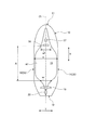
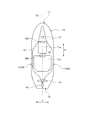
図1は、第1実施形態の摩擦低減装置を搭載した船舶の概略側面図、図2は、摩擦低減装置を搭載した船舶の概略底面図、図3は、空気供給系統を表す概略図である。
[First Embodiment]
FIG. 1 is a schematic side view of a ship equipped with the friction reducing device of the first embodiment, FIG. 2 is a schematic bottom view of the ship equipped with the friction reducing device, and FIG. 3 is a schematic diagram showing an air supply system. .
第1実施形態の船舶は、船長が100m以上の大型船舶であって、例えば、大型石油タンカー(VLCC,ULCC)、LNG船やLPG船、旅客船(カーフェリー)などであり、摩擦低減装置を搭載している。 The ship of the first embodiment is a large ship having a captain of 100 m or more, for example, a large oil tanker (VLCC, ULCC), an LNG ship, an LPG ship, a passenger ship (car ferry), etc., and is equipped with a friction reducing device. doing.
図1及び図2に示すように、船体10は、船首11と、船尾12と、船底13と、左舷14と、右舷15を有している。本実施形態では、船体10の船長方向(前後方向)をX方向、船幅方向(幅方向)をY方向、船高方向(上下方向)をZ方向として表している。そして、CLは、船体10の幅方向におけるセンターラインを表し、WLは、船体10の満載喫水線を表している。
As shown in FIGS. 1 and 2, the
船体10は、船尾12側に隔壁16により機関室17が区画され、この機関室17に主機関(例えば、ディーゼルエンジン)18が配置されている。この主機関18は、推進力を伝達するプロペラ19が駆動連結されている。また、船体10は、船尾12に船体10の方向を制御する舵20が設けられている。
In the
また、船体10は、空気供給機器室21と、船倉22と、甲板23と、甲板暴露部25と、隔壁26と、船底外板27と、船側外板28,29とを有している。空気供給機器室21は、船倉22より船首11側に配置されている。空気供給機器室21と船倉22は、隔壁26により仕切られている。甲板23は、空気供給機器室21及び船倉22の床面を形成している。甲板暴露部25は、例えば、船首11の上甲板であり、空気供給機器室21の上方に配置される。
Further, the
摩擦低減装置31は、空気供給装置32と、エアクーラ33と、通風筒34と、空気吸い込み口35と、空気吹き出し部36と、海水取入部37と、ポンプ38とを有している。空気吹き出し部36は、船首11側の船底13に配置されている。空気供給装置32及びエアクーラ33は、空気供給機器室21に設置されている。通風筒34及び空気吸い込み口35は、甲板暴露部25に配置されている。通風筒34は、空気供給機器室21に連通され、空気供給機器室21を換気するために用いられる。空気吸い込み口35は空気供給装置32に接続されている。空気供給装置32は、エアクーラ33を介して空気吹き出し部36に接続されている。海水取入部37は、ポンプ38を介してエアクーラ33に接続されている。
The
船底13は、船体10における船底外板27の平坦な部分(平坦面)に配置されており、船体10のセンターラインCL(船長方向X)に沿って船首11側に延出されると共に、船尾12側に延出され、船幅方向Yに沿って両側に延出されている。空気吹き出し部36と海水取入部37は、船底13における船体10のセンターラインCL上に配置され、海水取入部37が空気吹き出し部36より船首11側に配置されている。空気吹き出し部36は、船幅方向Yに沿って配置されている。
The ship bottom 13 is disposed on a flat portion (flat surface) of the
空気供給装置32は、空気吸い込み口35から吸い込んだ空気を加圧し、その加圧された圧縮空気をエアクーラ33から空気吹き出し部36に供給する。ポンプ38は、海水取入部37から取り入れられた海水をエアクーラ33に供給する。エアクーラ33は、海水を用いて圧縮空気を冷却する。エアクーラ33は、例えば、圧縮空気と海水を熱交換する熱交換器である。また、エアクーラ33は、圧縮空気中に海水を散布して圧縮空気を冷却するように構成してもよく、海水中に圧縮空気を吹き出して圧縮空気を冷却するように構成してもよい。空気吹き出し部36は、空気供給装置32から供給された圧縮空気を水中に吹き出す。即ち、船底13の空気吹き出し部36から水中に空気が吹き出され、この吹き出された空気により形成される気泡が平坦面となる船底13の表面に送り出され、この気泡により船底13が覆われることで船体10の摩擦抵抗が低減される。
The
また、船首11側の船底13に配置された空気吹き出し部36は、図3に示すように、船体10の内部に設けられる複数の気体室41と、この各気体室41内と船体10の外方とを仕切る仕切壁としての船底外板27と、船底外板27に設けられる複数の空気吹き出し口42とを有している。気体室41は、密閉された空間であって、エアクーラ33を介して空気供給装置32が接続されている。複数の空気吹き出し口42は、気体室41から船底外板27を貫通して船体10の外方、つまり、水中に流通する通路である。この複数の空気吹き出し口42は、船底13の船長方向(X方向)に沿うと共に、船幅方向(Y方向)に所定間隔を空けて配置されている。そのため、複数の空気吹き出し口42から水中に吹き出された圧縮空気は、気泡となり、船底13の平坦部を後方に流れると共に幅方向に拡散する。
Further, as shown in FIG. 3, the
空気供給装置32は、気体室41と、空気吹き出し口42と、圧縮機43と、主空気供給配管44と、メインチャンバ45と、複数の副空気供給配管(空気供給通路)46とを有している。圧縮機43は、空気取り込み配管47を介して空気吸い込み口35が接続されている。また、圧縮機43は、主空気供給配管44を介してメインチャンバ45が接続されている。この圧縮機43は、例えば、取り込んだ空気を500kPa以上(望ましくは、700kPa〜1300kPa)に加圧することができる。主空気供給配管44は、開閉弁48、流量計49、圧力計50が設けられている。
The
メインチャンバ45は、圧縮機43により加圧供給された圧縮空気を所定圧の状態で、所定量だけ貯留することができる。このメインチャンバ45は、主空気供給配管44の下流端部が接続されると共に、複数の副空気供給配管46の各上流側他端部がそれぞれ接続されている。この各副空気供給配管46は、下流側端部がそれぞれ気体室41に接続されている。副空気供給配管46は、流量調整弁51と遮断弁52が設けられている。
The
そのため、開閉弁48を開放して圧縮機43を駆動すると、圧縮機43は、取り込んだ空気を所定圧まで加圧し、主空気供給配管44を通してメインチャンバ45に送り、メインチャンバ45は、圧縮空気を所定圧の状態で貯留する。ここで、流量調整弁51と遮断弁52を開放すると、メインチャンバ45の圧縮空気が各副空気供給配管46を介して各気体室41にそれぞれ供給され、各気体室41に供給された圧縮空気が複数の空気吹き出し口42から水中に吹き出され、気泡となって平坦面となる船底13の表面に沿って船尾12側に流れる。
Therefore, when the on-off
本実施形態の船舶は、図1及び図2に示すように、船底13において、少なくとも空気吹き出し部36より船尾12側に、船尾12側に向けて喫水が深くなる傾斜面61が設けられている。本実施形態では、船底13自体が、船尾12側に向けて喫水が深くなるように所定の傾斜角度θだけ傾斜した傾斜面61となっている。即ち、傾斜面61である船底13は、満載喫水線WLと平行な水平線WL1に対して、船尾12側に向けて船高方向Zの下方側に所定の傾斜角度θで傾斜している。
As shown in FIGS. 1 and 2, the ship according to the present embodiment is provided with an
但し、船底13の全域を傾斜させて傾斜面61を形成する必要はなく、空気吹き出し部36は、船長方向Xの中間位置より船首11側に設けられており、傾斜面61は、少なくともこの空気吹き出し部36より船尾12側に設けられていればよい。
However, it is not necessary to incline the entire region of the ship bottom 13 to form the
例えば、舵軸心の位置P1から、船首11側における船体10の前端と満載喫水線WLとの交点P2までの船長方向Xの長さを水線間長Lとする。このとき、傾斜面61は、舵軸心の位置P1から船首11側に水線間長Lの10%だけ移行した位置P3から、舵軸心の位置P1から船首11側に水線間長Lの90%だけ移行した位置P4との間の領域Aに設けられていることが好ましい。なお、傾斜面61の形成領域は、位置P1から位置P4までの領域Aに限らず、舵軸心の位置P1から船首11側に水線間長Lの20%だけ移行した位置から、舵軸心の位置P1から船首11側に水線間長Lの80%だけ移行した位置との間の領域に設けられていることが更に好ましい。
For example, the length in the ship length direction X from the position P1 of the rudder axis to the intersection P2 between the front end of the
また、傾斜面61は、船長方向Xに沿って水線間長Lの20%以上の領域に設けられることが好ましい。そして、この傾斜面61は、船長方向Xに沿う満載喫水線WL(水平線WL1)に対して、0.001度から2度の傾斜角度θに設定されることが好ましい。この傾斜角度θは、気泡の拡散幅に対する空気吹き出し部36からの長さにより実験に基づいて設定される。好ましくは、0.1度から0.2度の傾斜角度θである。
Further, the
そのため、圧縮空気が空気吹き出し部36から水中に吹き出されると、この圧縮空気が多数の気泡となって船底13の表面に沿って船尾12側に流れる。このとき、船底13の表面に沿って船尾12側に流れる多数の気泡は、船高方向Zの下方に拡散するが、船底13が船尾12側に向けて喫水が深くなる傾斜面61であることから、多数の気泡は、船尾12側に流れにくくなり、気泡の密度(ボイド率)が高くなる。そのため、船体10の摩擦抵抗低減効果が向上する。
Therefore, when the compressed air is blown into the water from the
図4は、船底に対する気泡位置を表すグラフである。図4に示すように、従来の船底は、船尾12側に向けて喫水が一定となる水平面であり、一点鎖線で表す気泡位置が船底から離間する方向に拡散することから、従来の船底と気泡位置との距離d1は、船尾12側に行くほどに大きくなり、気泡密度が減少することで船体10の摩擦抵抗低減効果が薄れてしまう。一方、本実施形態の船底13は、船尾12側に向けて喫水が深くなる傾斜面61であり、一点鎖線で表す気泡位置が船底から離間する方向に拡散するものの、本実施形態の船底13と気泡位置との距離d2は、船尾12側に行ってもほぼ一定に維持され、気泡密度が維持されることで船体10の摩擦抵抗低減効果が従来に比べて向上する。
FIG. 4 is a graph showing the bubble position with respect to the ship bottom. As shown in FIG. 4, the conventional ship bottom is a horizontal plane in which the draft is constant toward the stern 12, and the bubble position represented by the alternate long and short dash line diffuses away from the ship bottom. The distance d1 from the position increases as it goes toward the stern 12 side, and the effect of reducing the frictional resistance of the
このように第1実施形態の船舶にあっては、船底13の空気吹き出し部36から水中に空気を吹き出す摩擦低減装置31が搭載される船舶において、船底13は、少なくとも空気吹き出し部36より船尾12側に船尾12側に向けて喫水が深くなる傾斜面61が設けられる。
As described above, in the ship according to the first embodiment, in the ship on which the
従って、空気吹き出し部36から水中に吹き出された空気は、多数の気泡となって船底13の表面に沿って船尾12側に流れる。このとき、船底13に船尾12側に向けて喫水が深くなる傾斜面61が設けられていることから、多数の気泡は、船尾12側に流れにくくなって気泡の密度が高くなり、摩擦抵抗低減効果の向上を図ることができる。
Therefore, the air blown into the water from the
第1実施形態の船舶では、空気吹き出し部36を船長方向Xの中間位置より船首11側に設け、傾斜面61を舵軸心の位置P1から船首11側に水線間長Lの10%移行した位置P3から、舵軸心の位置P1から船首11側に水線間長L90%移行した位置P4との間の領域Aに設けている。従って、傾斜面61を船長方向Xにおける最適領域に設けることで、気泡の拡散を抑制して摩擦抵抗低減効果の向上を図ることができる。
In the ship of the first embodiment, the
第1実施形態の船舶では、傾斜面61を船長方向Xに沿って水線間長Lの20%以上の領域に設けている。従って、船長方向Xにおける傾斜面61の領域の長さを設定することで、気泡の拡散を抑制して摩擦抵抗低減効果の向上を図ることができる。
In the ship of the first embodiment, the
第1実施形態の船舶では、傾斜面61は、船長方向Xに沿う満載喫水線WLに対して、0.001度から2度の傾斜角度θに設定されている。従って、傾斜面61の最適な傾斜角度の領域を設定することで、造波抵抗、粘性圧力抵抗の増加を抑制しながら、粘性摩擦抵抗低減効果の向上を図ることができる。
In the ship of the first embodiment, the
[第2実施形態]
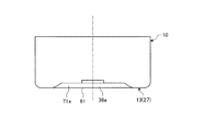
図5は、第2実施形態の摩擦低減装置を搭載した船舶の概略側面図、図6は、摩擦低減装置を搭載した船舶の概略底面図である。なお、上述した実施形態と同様の機能を有する部材には、同一の符号を付して詳細な説明は省略する。
[Second Embodiment]
FIG. 5 is a schematic side view of a ship equipped with the friction reducing device of the second embodiment, and FIG. 6 is a schematic bottom view of the ship equipped with the friction reducing device. In addition, the same code | symbol is attached | subjected to the member which has the same function as embodiment mentioned above, and detailed description is abbreviate | omitted.
第2実施形態の船舶は、図5及び図6に示すように、船底13において、少なくとも空気吹き出し部36より船尾12側に、船尾12側に向けて喫水が深くなる傾斜面62が設けられている。そして、本実施形態にて、傾斜面62は、幅が船幅Wの30%以上の領域に設けられている。即ち、船底13は、船体10のセンターラインCL(船長方向X)に沿って船首11側及び船尾12側に延出され、船首11側及び船尾12側に向けてその幅が小さくなっている。傾斜面62は、幅が船幅Wf=0.3Wより船尾12側で、船幅Wr=0.3Wより船首11側に設けられる。
As shown in FIGS. 5 and 6, the ship according to the second embodiment is provided with an
そして、船底13は、傾斜面62より船首11側に船長方向Xに沿って喫水が一定な船首側水平面63が設けられている。また、船底13は、傾斜面62より船尾12側に船長方向Xに沿って喫水が一定な船尾側水平面64が設けられている。即ち、傾斜面62と船首側水平面63とにおける船幅Wfが0.3Wであり、傾斜面62と船尾側水平面64とにおける船幅Wrが0.3Wである。但し、傾斜面62を空気吹き出し部36から船尾方向に所定距離離れた位置から船尾12側に設けてもよい。
The ship bottom 13 is provided with a bow-side
そのため、空気吹き出し部36から水中に吹き出された圧縮空気は、多数の気泡となって船底13の表面に沿って船尾12側に流れる。このとき、船底13の表面に沿って船尾12側に流れる多数の気泡は、傾斜面62を流れるときに船尾12側に流れにくくなり、気泡の密度(ボイド率)が高くなる。そのため、船体10の摩擦抵抗低減効果が向上する。
Therefore, the compressed air blown out into the water from the
このように第2実施形態の船舶にあっては、傾斜面62の幅を船幅Wの30%以上の領域に設けている。従って、傾斜面62を船長方向Xにおける最適領域に設けることで、気泡の拡散を抑制して摩擦抵抗低減効果の向上を図ることができる。
Thus, in the ship of the second embodiment, the width of the
第2実施形態の船舶では、船底13における傾斜面62より船首11側に船長方向Xに沿って喫水が一定な船首側水平面63を設けている。従って、船首11側での船体抵抗が低減して造波抵抗、粘性圧力抵抗の増加を抑制しながら、粘性摩擦抵抗低減効果の向上を図ることができる。
In the ship according to the second embodiment, a bow side
第2実施形態の船舶では、船底13における傾斜面62より船尾12側に船長方向Xに沿って喫水が一定な船尾側水平面64を設けている。従って、船尾12側での船体抵抗が低減して造波抵抗、粘性圧力抵抗の増加を抑制しながら、粘性摩擦抵抗低減効果の向上を図ることができる。
In the ship of the second embodiment, a stern side
[第3実施形態]
図7は、第3実施形態の摩擦低減装置を搭載した船舶の概略底面図である。なお、上述した実施形態と同様の機能を有する部材には、同一の符号を付して詳細な説明は省略する。
[Third Embodiment]
FIG. 7 is a schematic bottom view of a ship equipped with the friction reducing device of the third embodiment. In addition, the same code | symbol is attached | subjected to the member which has the same function as embodiment mentioned above, and detailed description is abbreviate | omitted.
第3実施形態の船舶は、図7に示すように、船底13に複数(本実施形態では、3個)の空気吹き出し部36a,36b,36cが船長方向Xに所定間隔を空けて設けられている。そして、船底13において、少なくとも船首11側の空気吹き出し部36aより船尾12側に、船尾12側に向けて喫水が深くなる傾斜面61が設けられている。
As shown in FIG. 7, the ship of the third embodiment is provided with a plurality (three in this embodiment) of
そのため、各空気吹き出し部36a,36b,36cから水中に吹き出された圧縮空気は、多数の気泡となって船底13の表面に沿って船尾12側に流れる。このとき、船底13の表面に沿って船尾12側に流れる多数の気泡は、傾斜面61を流れるときに船尾12側に流れにくくなり、気泡の密度(ボイド率)が高くなる。そのため、船体10の摩擦抵抗低減効果が向上する。
Therefore, the compressed air blown into the water from each of the
このように第3実施形態の船舶にあっては、船底13の船長方向Xに所定間隔を空けて複数の空気吹き出し部36a,36b,36cを設けている。従って、空気吹き出し部36a,36b,36cから船底13のセンターラインCLに沿って空気を吹き出すことで、船幅方向への気泡の拡散を抑制して摩擦抵抗低減効果の向上を図ることができる。
Thus, in the ship of 3rd Embodiment, the several
[第4実施形態]
図8は、第4実施形態の摩擦低減装置を搭載した船舶の概略底面図、図9は、摩擦低減装置を搭載した船舶の概略縦断面図である。なお、上述した実施形態と同様の機能を有する部材には、同一の符号を付して詳細な説明は省略する。
[Fourth Embodiment]
FIG. 8 is a schematic bottom view of a ship equipped with the friction reducing device of the fourth embodiment, and FIG. 9 is a schematic longitudinal sectional view of the ship equipped with the friction reducing device. In addition, the same code | symbol is attached | subjected to the member which has the same function as embodiment mentioned above, and detailed description is abbreviate | omitted.
第4実施形態の船舶は、図8及び図9に示すように、船底13に複数(本実施形態では、2個)の空気吹き出し部36a,36bが船長方向Xに所定間隔を空けて設けられている。そして、船底13において、少なくとも船首11側の空気吹き出し部36aより船尾12側に、船尾12側に向けて喫水が深くなる傾斜面61が設けられている。
As shown in FIGS. 8 and 9, the ship of the fourth embodiment is provided with a plurality of (two in this embodiment)
また、船底13において、各空気吹き出し部36a,36bより船尾12側に凹部71a,71bが設けられている。即ち、各凹部71a,71bは、船底13に矩形状をなして設けられており、船内側に凹んで形成されており、ほぼ一定な深さとなっている。各空気吹き出し部36a,36bは、各凹部71a,71b内における船首11側の端部に設けられている。但し、各凹部71a,71bを各空気吹き出し部36a,36bの船尾12側の直後に設けたり、所定距離だけ離れて設けたりしてもよい。
Further, in the bottom 13, recesses 71 a and 71 b are provided on the stern 12 side from the
そのため、各空気吹き出し部36a,36bから水中に吹き出された圧縮空気は、多数の気泡となって船底13の表面に沿って船尾12側に流れる。このとき、船底13の表面に沿って船尾12側に流れる多数の気泡は、各凹部71a,71b内に一時的に貯留され、船幅方向Yに拡散しにくくなり、また、傾斜面61を流れるときに船尾12側に流れにくくなり、気泡の密度(ボイド率)が高くなる。そのため、船体10の摩擦抵抗低減効果が向上する。
Therefore, the compressed air blown out into the water from each of the
なお、船底13に対する各凹部71a,71bの構成は、上述したものに限定されるものではない。図10は、第4実施形態の第1変形例を表す摩擦低減装置を搭載した船舶の概略縦断面図、図11は、第4実施形態の第2変形例を表す摩擦低減装置を搭載した船舶の概略縦断面図である。
In addition, the structure of each recessed
図10に示すように、船底13に複数(本実施形態では、2個)の空気吹き出し部36d,36eが船幅方向Yに所定間隔を空けて設けられている。また、船底13において、各空気吹き出し部36d,36eより船尾12側に1個の凹部71aが設けられている。即ち、凹部71aは、船底13に矩形状をなして設けられており、船内側に凹んで形成されており、ほぼ一定な深さとなっている。各空気吹き出し部36d,36eは、この凹部71a内における船首11側の端部に設けられている。
As shown in FIG. 10, a plurality (two in this embodiment) of
また、図11に示すように、船底13に複数(本実施形態では、2個)の空気吹き出し部36d,36eが船幅方向Yに所定間隔を空けて設けられている。また、船底13において、各空気吹き出し部36d,36eより船尾12側に複数(本実施形態では、2個)の凹部71c,71dが船幅方向Yに所定間隔を空けて設けられている。即ち、各凹部71c,71dは、船底13に矩形状をなして設けられており、船内側に凹んで形成されており、ほぼ一定な深さとなっている。各空気吹き出し部36d,36eは、この各凹部71c,71d内における船首11側の端部に設けられている。
In addition, as shown in FIG. 11, a plurality (two in this embodiment) of
このように第4実施形態の船舶にあっては、船底13は、空気吹き出し部36a,36b,36d,36eより船尾12側に凹部71a,71b,71c,71dが設けられている。従って、空気吹き出し部36a,36b,36d,36eから水中に吹き出された空気は、多数の気泡となって一時的に凹部71a,71b,71c,71dに貯留されることで船幅方向Yへの気泡の拡散が抑制され、摩擦抵抗低減効果の向上を図ることができる。
Thus, in the ship of the fourth embodiment, the bottom 13 is provided with the
[第5実施形態]
図12は、第5実施形態の摩擦低減装置を搭載した船舶の概略底面図、図13は、摩擦低減装置を搭載した船舶の概略縦断面図である。なお、上述した実施形態と同様の機能を有する部材には、同一の符号を付して詳細な説明は省略する。
[Fifth Embodiment]
FIG. 12 is a schematic bottom view of a ship equipped with the friction reducing device of the fifth embodiment, and FIG. 13 is a schematic longitudinal sectional view of the ship equipped with the friction reducing device. In addition, the same code | symbol is attached | subjected to the member which has the same function as embodiment mentioned above, and detailed description is abbreviate | omitted.
第5実施形態の船舶は、図12及び図13に示すように、船底13において、少なくとも空気吹き出し部36aより船尾12側に、船尾12側に向けて喫水が深くなる傾斜面61が設けられている。また、船底13において、空気吹き出し部36より船幅方向Yの外側に空気の拡散を抑制する一対のガイド部81が設けられている。各ガイド部81は、船底13(傾斜面61)における船幅方向Yの端部から所定長さだけセンターラインCLに寄った位置に船長方向Xに沿って設けられている。このガイド部81は、船底から外部に突出したものであるが、その突出量は、船尾12側に向けて一定であっても、減少または増加していてもよい。また、このガイド部81は、船長方向Xに平行であるが、船尾側に向けて広くなったり、狭くなったりしていてもよい。
As shown in FIGS. 12 and 13, the ship of the fifth embodiment is provided with an
そのため、空気吹き出し部36から水中に吹き出された圧縮空気は、多数の気泡となって船底13の表面に沿って船尾12側に流れる。このとき、船底13の表面に沿って船尾12側に流れる多数の気泡は、各ガイド部81により船幅方向Yの外側への拡散が抑制され、また、傾斜面61を流れるときに船尾12側に流れにくくなり、気泡の密度(ボイド率)が高くなる。そのため、船体10の摩擦抵抗低減効果が向上する。
Therefore, the compressed air blown out into the water from the
このように第5実施形態の船舶にあっては、船底13に空気吹き出し部36より船幅方向Yの外側に空気の拡散を抑制するガイド部81を設けている。従って、空気吹き出し部36から水中に吹き出された空気は、多数の気泡となってガイド部81により船幅方向Yへの気泡の拡散が抑制され、摩擦抵抗低減効果の向上を図ることができる。
As described above, in the ship according to the fifth embodiment, the
なお、上述した各実施形態にて、船底13に設けた傾斜面61,62を平坦面としたが、船長方向Xに沿って湾曲する曲面としてもよい。また、傾斜面61,62を船幅方向Yの全域に設けたが、センターラインCLに寄った領域だけに設けてもよい。
In addition, in each embodiment mentioned above, although the
10 船体
11 船首
12 船尾
13 船底
14 左舷(船側)
15 右舷(船側)
21 空気供給機器室
27 船底外板
28,29 船側外板
31 摩擦低減装置
32 空気供給装置
33 エアクーラ
34 通風筒
35 空気吸い込み口
36,36a,36b,36c,36d,36e 空気吹き出し部
37 海水取入部
38 ポンプ
61,62 傾斜面
63 船首側水平面
64 船尾側水平面
71a,71b,71c,71d 凹部
81 ガイド部
X 船長方向
Y 船幅方向
Z 船高方向
10
15 Starboard (ship side)
21 Air
Claims (10)
前記船底は、少なくとも前記空気吹き出し部より船尾側に前記船尾側に向けて喫水が深くなる傾斜面が設けられる、
ことを特徴とする船舶。 In a ship equipped with a friction reducing device that blows air to the outside from the air blowing part at the bottom of the ship,
The ship bottom is provided with an inclined surface where the draft becomes deeper toward the stern side at least on the stern side than the air blowing portion.
A ship characterized by that.
Priority Applications (2)
| Application Number | Priority Date | Filing Date | Title |
|---|---|---|---|
| JP2017051762A JP2018154198A (en) | 2017-03-16 | 2017-03-16 | Vessel |
| PCT/JP2018/008649 WO2018168585A1 (en) | 2017-03-16 | 2018-03-06 | Ship |
Applications Claiming Priority (1)
| Application Number | Priority Date | Filing Date | Title |
|---|---|---|---|
| JP2017051762A JP2018154198A (en) | 2017-03-16 | 2017-03-16 | Vessel |
Publications (2)
| Publication Number | Publication Date |
|---|---|
| JP2018154198A true JP2018154198A (en) | 2018-10-04 |
| JP2018154198A5 JP2018154198A5 (en) | 2019-08-22 |
Family
ID=63522220
Family Applications (1)
| Application Number | Title | Priority Date | Filing Date |
|---|---|---|---|
| JP2017051762A Pending JP2018154198A (en) | 2017-03-16 | 2017-03-16 | Vessel |
Country Status (2)
| Country | Link |
|---|---|
| JP (1) | JP2018154198A (en) |
| WO (1) | WO2018168585A1 (en) |
Family Cites Families (4)
| Publication number | Priority date | Publication date | Assignee | Title |
|---|---|---|---|---|
| JPS5078092A (en) * | 1973-11-13 | 1975-06-25 | ||
| JPS60163784A (en) * | 1984-02-07 | 1985-08-26 | Kazu Tanabe | Ship with air exhaust nozzles at bottom |
| JPS62143595U (en) * | 1986-03-05 | 1987-09-10 | ||
| CH670430A5 (en) * | 1986-09-12 | 1989-06-15 | Sulzer Ag |
-
2017
- 2017-03-16 JP JP2017051762A patent/JP2018154198A/en active Pending
-
2018
- 2018-03-06 WO PCT/JP2018/008649 patent/WO2018168585A1/en active Application Filing
Also Published As
| Publication number | Publication date |
|---|---|
| WO2018168585A1 (en) | 2018-09-20 |
Similar Documents
| Publication | Publication Date | Title |
|---|---|---|
| KR100188464B1 (en) | Method and device of reducing friction on a navigating vehicle | |
| AU2014206874B2 (en) | Fast ship | |
| US7581508B2 (en) | Monohull fast ship or semi-planing monohull with a drag reduction method | |
| US6748891B2 (en) | Frictional resistance reducing method, and ship with reduced frictional resistance | |
| KR101616261B1 (en) | Ship provided with bubble resistance reduction device, and method for reducing resistance of ship | |
| JPH07156859A (en) | Method to reduce friction of sailing body and friction reducing sailing body and generating method of microbubble used to reduce friction and device thereof | |
| JP2018154199A (en) | Vessel | |
| WO2018168585A1 (en) | Ship | |
| JP2017165386A (en) | Hull frictional resistance reduction device | |
| JPH10175588A (en) | Frictional resistance reducing device for ship | |
| RU2263602C2 (en) | High-speed vessel at delivery of air under bottom | |
| JP5806251B2 (en) | Ship equipped with bubble resistance reduction device and ship resistance reduction method | |
| JP2001106171A (en) | Frictional resistance reduced-ship and method of reducing frictional resistance of hull | |
| JPH09151913A (en) | Method of reducing friction of ship etc and friction reduced ship | |
| JP2009292202A (en) | Method for reducing frictional resistance force between ship body and water | |
| JP2001106173A (en) | Frictional resistance reduced-ship | |
| JP2004114996A (en) | Air cushion ship | |
| WO2001066410A1 (en) | Frictional resistance reducing method, and ship with reduced frictional resistance | |
| US7470161B2 (en) | Lifting body water jet propulsion inlet inductor | |
| JP3077032B1 (en) | Air cushion ship | |
| JP2023148982A (en) | Friction reduction device | |
| JP2007246041A (en) | Low frictional resistance enlarged ship | |
| JP2000203485A (en) | Friction resistance reducing ship | |
| JP6664907B2 (en) | Air generator | |
| KR20210002105A (en) | Ship |
Legal Events
| Date | Code | Title | Description |
|---|---|---|---|
| A711 | Notification of change in applicant |
Free format text: JAPANESE INTERMEDIATE CODE: A712 Effective date: 20180522 |
|
| A521 | Written amendment |
Free format text: JAPANESE INTERMEDIATE CODE: A523 Effective date: 20190711 |
|
| A621 | Written request for application examination |
Free format text: JAPANESE INTERMEDIATE CODE: A621 Effective date: 20190711 |
|
| A131 | Notification of reasons for refusal |
Free format text: JAPANESE INTERMEDIATE CODE: A131 Effective date: 20200428 |
|
| A02 | Decision of refusal |
Free format text: JAPANESE INTERMEDIATE CODE: A02 Effective date: 20201027 |