JP2018138186A - Pachinko game machine - Google Patents
Pachinko game machine Download PDFInfo
- Publication number
- JP2018138186A JP2018138186A JP2018079821A JP2018079821A JP2018138186A JP 2018138186 A JP2018138186 A JP 2018138186A JP 2018079821 A JP2018079821 A JP 2018079821A JP 2018079821 A JP2018079821 A JP 2018079821A JP 2018138186 A JP2018138186 A JP 2018138186A
- Authority
- JP
- Japan
- Prior art keywords
- game
- main
- main game
- ball
- symbol
- Prior art date
- Legal status (The legal status is an assumption and is not a legal conclusion. Google has not performed a legal analysis and makes no representation as to the accuracy of the status listed.)
- Pending
Links
Images


Abstract
Description
ぱちんこ遊技機に関する。 It relates to pachinko machines.
現在最も普及しているぱちんこ遊技機は、始動口(スタートチャッカー)に遊技球が入球したことを契機として、7セグ等の表示部上で「特別図柄」と称される図柄が変動表示され、当該特別図柄が特定態様(例えば「7」)となった場合、通常遊技状態よりも遊技者にとって利益状態の高い特別遊技状態{通常時は閉状態にある大入賞口(アタッカー)が所定条件で開放する内容の遊技}に移行するタイプの、いわゆる「デジパチ」と呼ばれている機種(従来の「第一種遊技機」)である。ここで、遊技者の利益に直結する特別図柄の表示制御の負担を軽減するために、前記の「特別図柄」とは別に、遊技の興趣性を高めるための演出用の「装飾図柄」と称される図柄が、前記特別図柄の変動とシンクロした形で、前記表示部よりもサイズが大きい演出用表示装置(例えば、液晶等のディスプレイ)上で変動表示される。そして、特別図柄の変動が開始されると装飾図柄もこれに合わせて変動を開始し、特別図柄が特定態様(例えば「7」)で停止した場合、装飾図柄もこれに合わせて所定態様(例えば「777」)で停止することとなる。そして、遊技者は、装飾図柄が所定態様で停止したことにより、特別遊技へ移行が確定したことを認識する。 The most popular pachinko machines are currently displayed with a special symbol on the 7-segment display, such as when a game ball enters the starter (start chucker). When the special symbol is in a specific mode (for example, “7”), a special gaming state that is more profitable for the player than the normal gaming state {a special winning opening (attacker) that is normally closed is a predetermined condition Is a model that is called “Digipachi” (conventional “first-class game machine”). Here, in order to reduce the burden of display control of special symbols that are directly linked to the interests of the player, in addition to the aforementioned “special symbols”, it is referred to as “decorative symbols” for the purpose of enhancing the fun of the game. The symbol to be displayed is variably displayed on an effect display device (for example, a display such as a liquid crystal) having a size larger than that of the display unit in a form synchronized with the variation of the special symbol. And when the change of the special symbol is started, the decorative symbol also starts to change accordingly, and when the special symbol stops in a specific mode (for example, “7”), the decorative symbol also changes to the predetermined mode (for example, “777”). Then, the player recognizes that the transition to the special game has been confirmed because the decorative symbol has stopped in a predetermined manner.
このように構成されたぱちんこ遊技機においては、演出用表示装置上の表示内容に係る視認性の向上や演出用表示装置の保護等を目的とし、当該演出用表示装置が設けられている空間と遊技球が転動する空間(いわゆる遊技領域)とを区分けするための部材(以下、センター役物やセンター飾りと呼ぶことがある)が設けられている。ここで、近年のぱちんこ遊技機においては、演出用表示装置の巨大化等に起因してセンター役物も巨大化する傾向にあり、特に、遊技領域の右側に設けられたレール部材(いわゆる外レール)近傍までセンター役物が伸長しているものも存在する。この場合、遊技領域の右側に打ちこまれた遊技球は、センター役物とレール部材との間隙によって形成されたルートを流下することとなるが、当該間隙幅が狭い場合(例えば、遊技球1個分以上2個分未満となる幅)には釘部材等を設けることが困難なことに起因して、当該ルートを流下する遊技球の球速が減速され難い構成となる。このような構成においては、遊技球の球速が減速され難いことに起因して、当該ルート出口に設けられた部材(例えば、アタッカー)の破損率が増大してしまう等の問題が発生しているため、従来より当該問題の解決手法が提案されている(例えば、特許文献1)。
In the pachinko gaming machine configured in this way, for the purpose of improving the visibility related to the display contents on the display device for production, protecting the display device for production, etc., and the space provided with the display device for production A member (hereinafter also referred to as a center accessory or a center decoration) is provided for distinguishing a space (a so-called game area) in which the game ball rolls. Here, in recent pachinko gaming machines, there is a tendency that the center role is also enlarged due to the enlargement of the display device for production, in particular, a rail member (so-called outer rail) provided on the right side of the game area. ) There are some where the center role extends to the vicinity. In this case, the game ball hit to the right of the game area flows down the route formed by the gap between the center role and the rail member, but the gap width is narrow (for example, the
しかしながら、このような手法では、遊技機の製造過程において発生し得る誤差(個体差)等によって、前述した問題を効果的に解決できない恐れがあるため、更なる改善の余地があるという課題が存在している。 However, with such a technique, there is a problem that there is room for further improvement because there is a possibility that the above-mentioned problem may not be effectively solved due to errors (individual differences) that may occur in the manufacturing process of gaming machines. doing.
本態様に係るぱちんこ遊技機は、
遊技盤の前面に形成された遊技領域と、
遊技領域と非遊技領域とを区画するレール部材と、
遊技領域へ向けて所定の発射強度で遊技球を放出可能な発射装置と、
遊技領域内において遊技盤から遊技者側に突出して設けられた、遊技球が流入可能な流路を備えた部材と
を有しており、
前記流路の入口は、前記レール部材の内壁に沿った、前記所定の発射強度が少なくとも最大の発射強度である場合における遊技球の流下経路上に配置されており、
前記流路を構成する壁面のうち、遊技盤の中心側の壁面および対向する壁面には一又は複数の突起部がそれぞれ一体成型されており、前記流路を流下する遊技球が前記一又は複数の突起部に衝突することで流下速度が減速されるよう構成され、前記流路の出口手前には前記突起部によって減速された遊技球の速度を更に減速させるコーナー構造が設けられ、
前記流路に一体成型された複数の突起部のうち、遊技球が最初に当接し得る突起部は前記レール部材側に配置された突起部であり、前記レール部材と前記流路を備えた部材との略当接部には微小な隙間が設けられている
ことを特徴とするぱちんこ遊技機である。
<付記>
尚、本態様とは異なる別態様について以下に列記しておくが、これらには何ら限定されることなく実施することが可能である。
本別態様に係るぱちんこ遊技機は、
遊技盤(例えば、遊技盤前面A1)の前面に形成された遊技領域(例えば、遊技領域A1a)と、
遊技領域(例えば、遊技領域A1a)と非遊技領域(例えば、遊技領域A1a外)とを区画するレール部材(例えば、右外レール部材A1−2)と、
遊技領域へ向けて所定の発射強度で遊技球を放出可能な発射装置(例えば、発射ハンドルB5−3)と、
遊技領域内において遊技盤から遊技者側に突出して設けられた、遊技球が流入可能な流路を備えた部材(例えば、減速形状A1−3a)と
を有しており、
前記流路の入口は、前記レール部材(例えば、右外レール部材A1−2)の内壁に沿った、前記所定の発射強度が少なくとも最大の発射強度である場合における遊技球の流下経路上に配置されており、
前記流路を構成する第一壁面(例えば、減速形状A1−3aの右壁面)と当該第一壁面(例えば、減速形状A1−3aの右壁面)と対向した第二壁面(例えば、減速形状A1−3aの左壁面)とが一体成型されており、且つ、第一壁面(例えば、減速形状A1−3aの右壁面)及び第二壁面(例えば、減速形状A1−3aの左壁面)には一又は複数の突起部(例えば、突起A1−3a−a、突起A1−3a−b、突起A1−3a−c及び突起A1−3a−d)がそれぞれ一体成型されており、前記流路を流下する遊技球が前記一又は複数の突起部(例えば、突起A1−3a−a、突起A1−3a−b、突起A1−3a−c及び突起A1−3a−d)に衝突することで流下速度が減速されるよう構成されている
ことを特徴とするぱちんこ遊技機である。
The pachinko gaming machine according to this aspect is
A game area formed on the front of the game board;
A rail member that partitions a gaming area and a non-gaming area;
A launcher capable of releasing a game ball at a predetermined launch intensity toward the game area;
And a member provided with a flow path through which a game ball can flow, provided to protrude from the game board to the player side in the game area,
The inlet of the flow path is disposed along the flow path of the game ball along the inner wall of the rail member when the predetermined firing strength is at least the maximum firing strength,
Of the wall surfaces constituting the flow path, one or a plurality of protrusions are integrally formed on the wall surface on the center side of the game board and the opposite wall surface, and the game ball flowing down the flow path is the one or more game balls. It is configured to reduce the flow velocity by colliding with the protruding portion of, and a corner structure for further reducing the speed of the game ball decelerated by the protruding portion is provided before the outlet of the flow path,
Of the plurality of protrusions integrally molded in the flow path, the protrusion that the game ball can first contact is a protrusion disposed on the rail member side, and the member including the rail member and the flow path It is a pachinko gaming machine characterized in that a minute gap is provided in the substantially abutting portion.
<Appendix>
In addition, although the different aspect different from this aspect is listed below, it can implement without being limited to these at all.
The pachinko gaming machine according to this different aspect is
A game area (for example, game area A1a) formed on the front surface of the game board (for example, game board front surface A1);
A rail member (e.g., right outer rail member A1-2) that partitions a gaming area (e.g., gaming area A1a) and a non-gaming area (e.g., outside gaming area A1a);
A launcher (e.g., launch handle B5-3) capable of releasing a game ball at a predetermined launch intensity toward the game area;
And a member (for example, a deceleration shape A1-3a) provided with a flow path through which a game ball can flow in provided in the game area so as to protrude from the game board to the player side.
The inlet of the flow path is disposed on the flow path of the game ball along the inner wall of the rail member (for example, the right outer rail member A1-2) when the predetermined firing strength is at least the maximum firing strength. Has been
A first wall surface (for example, the right wall surface of the deceleration shape A1-3a) constituting the flow path and a second wall surface (for example, the deceleration shape A1) facing the first wall surface (for example, the right wall surface of the deceleration shape A1-3a). -3a and the second wall surface (for example, the left wall surface of the deceleration shape A1-3a) and the second wall surface (for example, the left wall surface of the deceleration shape A1-3a). Or the some protrusion part (For example, protrusion A1-3a-a, protrusion A1-3a-b, protrusion A1-3a-c, and protrusion A1-3a-d) is integrally molded, respectively, and flows down the said flow path. The game ball collides with the one or more protrusions (for example, the protrusion A1-3a-a, the protrusion A1-3a-b, the protrusion A1-3a-c, and the protrusion A1-3a-d), and the flow-down speed is reduced. Pachinko machines characterized by being configured A.
本態様に係るぱちんこ遊技機によれば、強めに発射された遊技球の球速を効果的に減速できるという効果を奏する。 According to the pachinko gaming machine according to this aspect, it is possible to effectively decelerate the ball speed of the game ball that has been strongly launched.
はじめに、本明細書における各用語の意義について説明する。「入球口」とは、始動口や大入賞口といった遊技進行に直接的に関与するもののみならず、一般入賞口のような賞球払出のみが行われるものも含み、また、賞球払出が行われないもの(いわゆるゲート)をも含む概念である(よって、「入球口誘導部材」によって遊技球が誘導される入球口とは、これらすべてのものが含まれる)。「球受部材」とは、一般的には方形箱状の部材であるが、これには限定されず、例えば、湾曲した壁面を有する箱状の部材や、複数の異なる平板上の部材が近接(当接)して方形箱状をなすような態様をも含まれる。「レール部材」とは、単一のレール(モノレール)であってもよいし、複数のレールから構成されるものであってもよく、要するに案内路の役割を果たすものであれば、その態様には特に限定されるものではない。「可変部材の移動態様が所定態様とは異なる特殊態様」とは、例えば、所定態様における可変部材の移動速度と特殊態様における可変部材の移動速度とが相違する、所定態様における可変部材の移動距離と特殊態様における可変部材の移動距離とが相違する、所定態様における可変部材の移動パターンと特殊態様における可変部材の移動パターンとが相違する、等を挙げることができる。「遊技の進行に係る情報」とは、遊技の結果に影響を与える情報{例えば、抽選乱数(遊技の結果に影響を与えるいわゆる「基本乱数」、具体的には、特別遊技の移行と関連した「当選乱数」、識別図柄の変動態様を決定するための「変動態様決定乱数」、停止図柄を決定する「図柄決定乱数」、特別
遊技後に特定遊技に移行するか否かを決定する「当り図柄決定乱数」等を挙げることができる。また、「遊技用乱数」は、一種類でも複数種類でもよい。)や抽選乱数に紐づく情報、等}のみならず、遊技機の動作状態に係る情報(例えば、エラー発生情報、設定変更動作状態に係る情報、等)をも含む概念である。
First, the meaning of each term in this specification will be described. “Pitch entrance” includes not only those that are directly involved in the game progress such as start entrances and grand prize exits, but also those that only pay out prize balls such as general prize entrances. This is also a concept that includes what is not performed (so-called gate) (thus, the entrance where the game ball is guided by the “entrance entrance guiding member” includes all of these). The “ball receiving member” is generally a rectangular box-shaped member, but is not limited thereto. For example, a box-shaped member having a curved wall surface or a plurality of members on different flat plates are close to each other. A mode of forming a rectangular box shape by abutting is also included. The “rail member” may be a single rail (monorail) or may be composed of a plurality of rails. Is not particularly limited. “The special mode in which the movement mode of the variable member is different from the predetermined mode” is, for example, the moving distance of the variable member in the predetermined mode in which the moving speed of the variable member in the predetermined mode is different from the moving speed of the variable member in the special mode. And the movement distance of the variable member in the special mode are different from each other, the movement pattern of the variable member in the predetermined mode is different from the movement pattern of the variable member in the special mode, and the like. “Information relating to the progress of the game” refers to information that affects the outcome of the game {eg, a lottery random number (a so-called “basic random number that affects the outcome of the game, specifically related to the transition of special games” “Winning random number”, “Fluctuation mode determination random number” for determining the variation mode of the identification symbol, “Design determination random number” for determining the stop symbol, “Decision symbol for determining whether to shift to a specific game after a special game” In addition, the “game random number” may be one type or a plurality of types.) And the information associated with the lottery random number, etc.}, as well as information on the operating state of the gaming machine (For example, error occurrence information, information related to a setting change operation state, etc.).
以下、本実施形態について図面を用いて説明する。まず、本実施形態に係る遊技機は、例えば、従来の第1種(所謂デジパチタイプ)、第2種(所謂ハネモノタイプ)、第3種(所謂権利物タイプ)、電役(所謂一般電役、所謂普通電役)、一般機等、又はこれらの機能を複数有する複合機(例えば、第1種第1種複合機)等の、遊技媒体が遊技球である弾球式遊技機である。尚、アレンジボール機、雀球機、ぱちんこ式スロットマシン機、コインゲーム機等のアーケードマシン、各種ゲーム機を概念することができ、要するに、遊技媒体の流下による遊技を実現する遊技領域を有するあらゆる遊技機が含まれる。以下、本実施形態として、デジパチ遊技(1種遊技、図柄変動遊技ともいう)を実現する所謂1種1種複合機タイプのぱちんこ遊技機について例示説明する。 Hereinafter, the present embodiment will be described with reference to the drawings. First, the gaming machine according to the present embodiment includes, for example, a conventional first type (so-called digipachi type), second type (so-called honey monotype), third type (so-called right property type), electric role (so-called general electric role). A so-called ordinary electric machine), a general machine, or a multi-function machine having a plurality of these functions (for example, a first-type first-type multi-function machine) is a ball-type game machine in which a game medium is a game ball. Arcade machines such as arrange ball machines, sparrow ball machines, pachinko slot machines, coin game machines, and various game machines can be conceptualized. In short, any game area that realizes games by the flow of game media. Includes gaming machines. Hereinafter, as this embodiment, a so-called 1-type 1-type multi-function machine pachinko game machine that realizes a digipachi game (also referred to as a 1-type game or a symbol variation game) will be described.
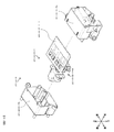
まず、図1〜図4を参照しながら、本実施形態に係るぱちんこ遊技機の前面側の基本構造を説明する。はじめに、図1及び図2に示されるように、本実施形態に係るぱちんこ遊技機は、大別すると遊技機枠ユニット群Bと遊技盤Aとに分けられ、遊技機枠ユニット群B及び遊技盤Aを構成する各ユニットの夫々を組み付けて形成されている。以下、遊技機枠ユニット群B及び遊技盤Aを構成する各ユニットについて順に説明する。 First, the basic structure of the front side of the pachinko gaming machine according to the present embodiment will be described with reference to FIGS. First, as shown in FIG. 1 and FIG. 2, the pachinko gaming machine according to the present embodiment is roughly divided into a gaming machine frame unit group B and a gaming board A, and the gaming machine frame unit group B and the gaming board. Each unit constituting A is assembled and formed. Hereinafter, the units constituting the gaming machine frame unit group B and the gaming board A will be described in order.
次に、ぱちんこ遊技機の遊技機枠ユニット群Bは、外枠ユニットB1、前枠(又は中枠)ユニットB2、透明板ユニット(又はガラスユニット)B3、扉ユニット(又は前枠ユニット、ガラス扉ユニット)B4、球皿ユニットB5(上球皿B5−1、下球皿B5−2及び発射ハンドルB5−3を含む)を主体として構成される。 Next, the gaming machine frame unit group B of the pachinko gaming machine includes an outer frame unit B1, a front frame (or middle frame) unit B2, a transparent plate unit (or glass unit) B3, a door unit (or front frame unit, glass door). Unit) B4 and a ball tray unit B5 (including an upper ball tray B5-1, a lower ball tray B5-2, and a firing handle B5-3).
外枠ユニットB1は、ぱちんこ遊技機を設置すべき位置に固定するための枠体であり、上下左右の枠杆(上枠杆B1d、下枠杆B1e、左枠杆B1a、右枠杆B1b)及び幕板B1cを、額縁状に適宜組み付けてユニット化されている。ここで、左枠杆B1aには、前枠ユニットB2を組み付けるための上下1組の前枠用ヒンジB1a−1が固着され、右枠杆B1bには、前枠ユニットB2を施錠するための外枠側の施錠金具(不図示)が固着されている。また、本実施形態では、幕板B1cにて、遊技状態に応じた音声を出力可能なスピーカ114が配設されており、左右の枠杆(左枠杆B1a、右枠杆B1b)が金属により、上下の枠杆(上枠杆B1d、下枠杆B1e)が木材により、幕板B1cが樹脂により、夫々形成されている。
The outer frame unit B1 is a frame for fixing the pachinko gaming machine to a position where it is to be installed, and the upper, lower, left and right frame fences (upper frame collar B1d, lower frame collar B1e, left frame collar B1a, right frame collar B1b). The curtain plate B1c is assembled in a frame shape as a unit. Here, a pair of upper and lower front frame hinges B1a-1 for assembling the front frame unit B2 is fixed to the left frame rod B1a, and an outer frame for locking the front frame unit B2 is fixed to the right frame rod B1b. A frame side locking bracket (not shown) is fixed. Further, in the present embodiment, the
前枠ユニットB2は、外形サイズが、外枠ユニットB1の開口部分に整合する枠体であり、外枠ユニットB1に設けられた前枠用ヒンジB1a−1及び施錠金具(不図示)と、前枠ユニットB2の適宜位置に設けられた(これらに対応した)ヒンジ機構B2a−1並びに施錠装置(不図示)により、外枠ユニットB1に対して横開き開閉可能、且つ施錠可能に取り付けられる。ここで、前枠ユニットB2には、遊技球を発射する発射機構、遊技盤Aを着脱可能に収容させるための遊技盤収容機構、賞球を付与するための賞球払出機構や、遊技済み球を誘導又は回収するための遊技済み球排出機構等が設けられている(詳細図示は省略)。本実施形態では、基体を成し遊技盤収容機構が形成されると共に発射機構の取り付けられた前枠本体B2aと、前枠本体B2aに着脱可能に取り付けられ、賞球払出機構、遊技済み球排出機構が形成された裏機構ユニットB2bと、から前枠ユニットB2が形成されている。また、前枠本体B2aの左側部には、後述する扉ユニットB4を組み付けるための上下1組のガラス枠用ヒンジB2a−2が設けられており、前枠本体B2aの右側部に扉ユニットB4を施錠するためのガラス枠用施錠装置(不図示)が設けられている。更に前枠本体B2aの下部には、後述する球皿ユニットB5を組み付けるための
球皿ユニット支持機構(球皿用ヒンジB2a−3を含む)が設けられている。
The front frame unit B2 is a frame whose outer size matches the opening of the outer frame unit B1, and includes a front frame hinge B1a-1 and a locking bracket (not shown) provided on the outer frame unit B1. A hinge mechanism B2a-1 and a locking device (not shown) provided at appropriate positions of the frame unit B2 and a locking device (not shown) are attached to the outer frame unit B1 so as to be openable and closable and lockable. Here, the front frame unit B2 includes a launching mechanism for launching a game ball, a game board housing mechanism for detachably housing the game board A, a prize ball payout mechanism for giving a prize ball, A game-completed ball discharge mechanism for guiding or collecting the game is provided (detailed illustration is omitted). In the present embodiment, a base board B2a that forms a base and forms a game board accommodation mechanism and is attached to a launch mechanism, and is detachably attached to the front frame body B2a. A front frame unit B2 is formed from the back mechanism unit B2b on which the mechanism is formed. Further, a pair of upper and lower glass frame hinges B2a-2 for assembling a door unit B4, which will be described later, is provided on the left side of the front frame body B2a, and the door unit B4 is attached to the right side of the front frame body B2a. A glass frame locking device (not shown) for locking is provided. Further, a ball tray unit support mechanism (including a ball tray hinge B2a-3) for assembling a ball tray unit B5 described later is provided at the lower portion of the front frame body B2a.
透明板ユニットB3は、複数枚(例えば2枚)のガラスやアクリル板などの透明板B3aを所定の間隔(20mm程度)をあけて平行に保持するためのものであり、コの字状の第一部材B3bに形成されたガラス保持部(不図示)に透明板B3aを挿入した後に、挿入部分を遮蔽する第二部材B3cをはめ込み接着して一体化されて形成される。尚、透明板ユニットB3(特に、透明板B3a)は、後述する扉ユニットB4の開口面を介して、後述する遊技盤Aの遊技領域A1aを透視可能で且つ、当該開口面から異物が進入しない(当該開口面から遊技盤A及び遊技領域A1aへアクセス困難となる)ように取り付けられる。 The transparent plate unit B3 is for holding a plurality of (for example, two) transparent plates B3a such as glass and acrylic plates in parallel with a predetermined interval (about 20 mm). After the transparent plate B3a is inserted into a glass holding portion (not shown) formed on the one member B3b, the second member B3c that shields the insertion portion is fitted and bonded to be integrated. The transparent plate unit B3 (particularly, the transparent plate B3a) can see through a game area A1a of a game board A (described later) through an opening surface of a door unit B4 (described later), and foreign matter does not enter from the opening surface. (It is difficult to access the game board A and the game area A1a from the opening surface).
扉ユニット(ガラス扉)B4は、前枠ユニットB2に設けられたガラス枠用ヒンジB2a−2及びガラス枠用施錠装置(不図示)と、扉ユニットB4の適宜位置に設けられた(これらに対応した)ヒンジ機構並びに施錠金具(不図示)により、前枠ユニットB2に対して横開き開閉可能、且つ施錠可能に取り付けられる。尚、扉ユニットB4は、外形サイズが、遊技盤Aの外形に略整合する大きさで構成されており、中央に透明板ユニットB3よりも小さい面積にて開口部B4aが設けられ、透明板ユニットB3を介して後述する遊技盤A及び遊技領域A1aが視認可能となっている。ここで、扉ユニットB4には、その背面側に、透明板ユニットB3を保持する透明板ユニット保持部B4b、開口部B4aの周囲に電飾効果や視覚的効果が得られるような装飾が施された装飾部B4c等も形成されている。尚、本実施形態では、扉ユニットB4の左右上部に夫々スピーカ114(不図示)が配設されている。 The door unit (glass door) B4 is provided at an appropriate position of the glass frame hinge B2a-2 and the glass frame locking device (not shown) provided in the front frame unit B2, and the door unit B4 (corresponding to these). It is attached to the front frame unit B2 so that it can be opened and closed laterally and locked by a hinge mechanism and a locking metal fitting (not shown). The door unit B4 is configured to have an outer size substantially matching the outer shape of the game board A, and an opening B4a is provided in the center with an area smaller than the transparent plate unit B3. A game board A and a game area A1a, which will be described later, are visible through B3. Here, the door unit B4 is decorated on the back side thereof so as to obtain an electric decoration effect and a visual effect around the transparent plate unit holding portion B4b for holding the transparent plate unit B3 and the opening B4a. A decorative part B4c and the like are also formed. In the present embodiment, speakers 114 (not shown) are provided on the upper left and right sides of the door unit B4.
球皿ユニットB5は、前枠ユニットB2に設けられた球皿ユニット支持機構(球皿用ヒンジB2a−3を含む)と、球皿ユニットB5の適宜位置に設けられた係合部材(例えば、係合部材B5a−1)とにより、前枠ユニットB2に対して着脱可能に取り付けられる。尚、球皿ユニットB5は、扉ユニットB4を開閉した状態でのみ前枠ユニットB2から着脱可能とすることで、当該遊技機専用の鍵を設けずとも、遊技に供されている状態では取り外しが困難な構造(例えば、扉ユニットB4の一部と球皿ユニットB5の一部がラップする構造)を採用している。ここで、球皿ユニットB5は、外形サイズが、方形状に形成され、上部にて発射装置に遊技球を供給する上球皿B5−1、下部にて多数の賞球が払い出されたことにより、上球皿B5−1に過剰な遊技球が供給された場合に当該過剰分の遊技球を貯留可能な下球皿B5−2が形成され、下球皿B5−2の右側に、遊技者の操作により発射装置の発射強度(遊技球の打球位置)を調整する発射ハンドルB5−3が設けられている。また、球皿ユニットB5の一部表面(本例では、上球皿B5−1の上面)には、遊技者が演出時に操作するサブ入力ボタンB5−4、遊技球の貸し出し要求を行うための貸出操作部(不図示)が配設されている。 The ball tray unit B5 includes a ball tray unit support mechanism (including a ball tray hinge B2a-3) provided in the front frame unit B2, and an engagement member (for example, an engagement member) provided at an appropriate position of the ball tray unit B5. It is detachably attached to the front frame unit B2 by the joint member B5a-1). The ball tray unit B5 can be detached from the front frame unit B2 only when the door unit B4 is opened and closed, so that the ball tray unit B5 can be removed in a state where it is used for gaming without providing a dedicated key for the gaming machine. A difficult structure (for example, a structure in which a part of the door unit B4 and a part of the ball tray unit B5 wrap) is employed. Here, the ball tray unit B5 has an outer shape formed in a square shape, and an upper ball tray B5-1 that supplies game balls to the launching device at the upper part, and a large number of prize balls are paid out at the lower part. Thus, when an excessive game ball is supplied to the upper ball tray B5-1, a lower ball tray B5-2 capable of storing the excess game balls is formed, and a game is placed on the right side of the lower ball tray B5-2. A firing handle B5-3 is provided for adjusting the firing strength (game ball hitting position) of the launching device by the user's operation. In addition, a sub-input button B5-4 operated by the player at the time of production, a lending request for the game ball is made on a part of the surface of the ball tray unit B5 (in this example, the upper surface of the upper ball tray B5-1). A lending operation unit (not shown) is provided.
尚、本実施形態における遊技機枠ユニット群Bの概略構成は以上の通りであるが、前述したように、遊技機枠ユニット群Bは複数のユニットから構成されており、より具体的には、外枠ユニットB1の前方に前枠ユニットB2(遊技盤Aを内包)、前枠ユニットB2の前方に透明板ユニットB3、扉ユニットB4及び球皿ユニットB5が、それぞれ着脱可能(又は開閉可能)に構成されている。このため、それぞれのユニットの整合部分には、開閉操作や着脱操作を容易にするための微少な間隙を有することとなる。よって、本実施形態においては、図示は省略するが、各ユニットの整合部分には、異物の混入を抑止するために、間隙が直線的にならないように整合部分にラビリンス構造(断面視で凹凸形状となるような構造)を採用していることが望ましい(但し、これには限定されない)。 In addition, although the schematic structure of the gaming machine frame unit group B in the present embodiment is as described above, as described above, the gaming machine frame unit group B is composed of a plurality of units, and more specifically, Front frame unit B2 (including game board A) in front of outer frame unit B1, and transparent plate unit B3, door unit B4, and ball tray unit B5 are detachable (or openable) in front of front frame unit B2. It is configured. For this reason, the alignment part of each unit has a minute gap for facilitating the opening / closing operation and the attaching / detaching operation. Therefore, in this embodiment, although not shown in the drawings, the alignment portion of each unit has a labyrinth structure (uneven shape in a cross-sectional view) so that the gap does not become linear in order to prevent foreign matter from entering. It is desirable to employ a structure such that (but not limited to).
尚、本実施形態では、扉ユニットB4と球皿ユニットB5とが別体の構造を採用しているが、双方を一体構造を採用しても良い。また、本実施形態においては、遊技結果に応じ
て物理的な遊技媒体を払い出す構造を採用しているが、電子式な媒体管理を行うよう構成してもよい。その場合には、下球皿B5−2や賞球払出機構等は不要となり、遊技済み球を上皿B5−1に戻して電子的な管理を行う遊技機形態(いわゆる封入循環形態)が採用され、球皿ユニットB5或いは扉ユニットB4等に電子媒体による精算・貸出用の操作部が配設されることになることを補足しておく。
In the present embodiment, the door unit B4 and the ball tray unit B5 adopt separate structures, but both may adopt an integral structure. Further, in the present embodiment, a structure in which a physical game medium is paid out according to the game result is adopted. However, electronic medium management may be performed. In that case, the lower ball tray B5-2, the prize ball payout mechanism, etc. are not required, and a game machine form (so-called enclosed circulation form) in which a game-completed ball is returned to the upper plate B5-1 for electronic management is adopted. In addition, it will be supplemented that an operation unit for settlement / rental using an electronic medium is arranged in the ball tray unit B5 or the door unit B4.
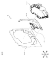
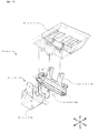
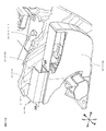
次に、図2を参照しながら、遊技盤Aを説明する。遊技盤Aは、遊技球が転動する遊技領域(詳細後述)を備えた遊技盤前面A1と、演出用役物(可動体)及びその駆動機構が備えられていると共に入賞球やアウト球を回収するための機構を備えた遊技盤背面A2と、を備えている。そして、遊技盤前面A1は遊技盤背面A2に組み付けられており、この組み付けられたものが前述した前枠ユニットB2に取り付けられている。 Next, the game board A will be described with reference to FIG. The game board A is provided with a game board front face A1 having a game area (details will be described later) on which a game ball rolls, an effect player (movable body), and a drive mechanism thereof. And a game board rear surface A2 having a mechanism for collecting. And the game board front surface A1 is assembled | attached to the game board back surface A2, and this assembled thing is attached to the front frame unit B2 mentioned above.
次に、図3及び図4を参照しながら、遊技盤前面A1を詳述する。まず、図3に示すように、遊技盤前面A1は、遊技板A1−1と、遊技板A1−1に嵌め込まれる大入賞口ユニットA1−4と、遊技板A1−1に嵌め込められる右外レール部材A1−2と、遊技板A1−1に嵌め込められるセンター役物A1−3と、を有している(左側の外レール部材等は省略)。 Next, the game board front surface A1 will be described in detail with reference to FIGS. First, as shown in FIG. 3, the game board front surface A1 has a game board A1-1, a big prize opening unit A1-4 fitted into the game board A1-1, and a right outside fitted into the game board A1-1. It has a rail member A1-2 and a center accessory A1-3 fitted into the game board A1-1 (the left outer rail member and the like are omitted).
ここで、図4は、遊技板A1−1に、これら(大入賞口ユニットA1−4、右外レール部材A1−2、センター役物A1−3等)が嵌め込められた状態を前面から眺めた図である。図4に示すように、遊技盤前面A1には、遊技球が転動し得る領域である遊技領域A1aが形成されている。具体的には、遊技領域A1aは、外レールA1−5と、内レールA1−6と、右外レール部材A1−2と、センター役物A1−3の外周壁(及び後述する減速形状A1−3a)と、等で区画された領域である。尚、センター役物A1−3の外壁にはワープルート(不図示)が設けられており、当該ワープルートを介して、遊技球がセンター役物A1−3内で転動し、その後再びセンター役物A1−3外に放出されるように構成されている。よって、センター役物A1−3内の一部も遊技領域A1aの一部を構成する。更に、図4に示すように、遊技盤前面A1には、第1主遊技始動口A1−7、第2主遊技始動口A1−8、補助遊技始動口A1−4−4、大入賞口入賞部A1−4a、アウト口A1−2a、演出表示装置A2−3等が備えられている。更に、詳細図示は省略するが、遊技盤前面A1の適宜位置にて、第1主遊技図柄表示装置2130、第2主遊技図柄表示装置2230、補助遊技図柄表示装置2420等も備えられている。 Here, FIG. 4 is a view of the state in which these (large prize winning unit A1-4, right outer rail member A1-2, center accessory A1-3, etc.) are fitted to the game board A1-1 from the front. It is a figure. As shown in FIG. 4, a game area A1a, which is an area in which a game ball can roll, is formed on the front surface A1 of the game board. Specifically, the game area A1a includes an outer rail A1-5, an inner rail A1-6, a right outer rail member A1-2, and an outer peripheral wall of a center accessory A1-3 (and a deceleration shape A1- described later). 3a), and the like. A warp route (not shown) is provided on the outer wall of the center accessory A1-3, and the game ball rolls in the center accessory A1-3 via the warp route, and then the center role again. It is comprised so that it may be discharged | emitted out of the thing A1-3. Therefore, a part in the center bonus A1-3 also constitutes a part of the game area A1a. Further, as shown in FIG. 4, the first main game starting port A1-7, the second main game starting port A1-8, the auxiliary game starting port A1-4-4, and the grand prize winning award are placed on the front A1 of the game board. A part A1-4a, an outlet A1-2a, an effect display device A2-3, and the like are provided. Further, although not shown in detail, a first main game symbol display device 2130, a second main game symbol display device 2230, an auxiliary game symbol display device 2420, and the like are also provided at appropriate positions on the front surface A1 of the game board.
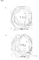
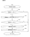
次に、図5及び図6を参照しながら、本実施形態の特徴部分の説明に先立ち、遊技内容の説明をする。まず、図5(a)に示されるように、ぱちんこ遊技において遊技者は、通常時には遊技領域左側を狙うこと(発射装置による遊技球の発射強度が弱い場合であり、例えば、所謂ブッコミ打ち)で第1主遊技始動口A1−7を狙い、図5(b)に示されるように、大当り時及び時短遊技時(確率変動状態の時短遊技時を含む)には遊技領域右側を狙うこと{発射装置による遊技球の発射強度が強い(少なくとも発射強度=最大を含む)場合であり、例えば、所謂強め打ち、ゴム打ち}で、大入賞口入賞部A1−4a及び第2主遊技始動口A1−8を狙う、という遊技が実行される(以下、前者における遊技球の流下経路を左打ちルート、後者における遊技球の流下経路を右打ちルートと呼ぶことがある)。そして、遊技球が右打ちルートを流下した場合、時短遊技時等である状況下では、図6(a)に示されるように、閉状態にある大入賞口入賞部A1−4aによって、当該流下した遊技球が第2主遊技始動口A1−8側へ誘導され、大当り時である状況下では、図6(b)に示されるように、開状態にある大入賞部A1−4a内部へと当該流下した遊技球が誘導されることとなる。このような遊技性を踏まえ、以下で本実施形態における特徴部分について詳述する。 Next, with reference to FIG. 5 and FIG. 6, the game content will be described prior to the description of the characteristic part of the present embodiment. First, as shown in FIG. 5 (a), in a pachinko game, the player usually aims at the left side of the game area (when the launching intensity of the game ball by the launching device is weak, for example, so-called bukkomi hitting). Aim at the first main game start opening A1-7, and as shown in FIG. 5B, aim at the right side of the game area at the time of big hit and short-time games (including short-time games in the probability variation state). This is a case where the launching strength of the game ball by the device is strong (including at least firing strength = maximum), for example, so-called strong hitting, rubber hitting, and the big winning opening winning portion A1-4a and the second main game starting opening A1- A game of aiming at 8 is executed (hereinafter, the flow path of game balls in the former may be called a left-handed route, and the flow path of game balls in the latter may be called a right-handed route). Then, when the game ball flows down the right-handed route, in the situation such as a short-time game, etc., as shown in FIG. When the game ball is guided to the second main game start opening A1-8 and is in a big hit, as shown in FIG. 6 (b), the open winning portion A1-4a is opened. The flowed game ball will be guided. Based on such game characteristics, the characteristic part in this embodiment is explained in full detail below.
(特徴部分1に係る課題)
次に、図7及び図8を参照しながら、右打ちルートを流下する遊技球を減速する部材(以下、減速形状と呼ぶことがある)における、従来技術の問題点について説明する。従来における減速形状は、図7に示されるように、減速形状の右壁面を構成する部材A1−2bと、減速形状の左壁面を構成するセンター役物A1−3と、が別部材によって構成されていた(本例では、レール飾りA1−2にて、減速形状の右壁面を構成する部材A1−2bが一体成型されている)。このような構成では、当該部材A1−2bを遊技板A1−1に組み付ける作業と、センター役物A1−3を遊技板A1−1に組み付ける作業と、が別々の作業であるため、減速形状の右壁面と左壁面の組み付けが別々の作業となる。その結果、図8に示されるように、減速形状の通路幅w1は、組み付け作業時において、設計幅と誤差が生じるものであった。そのため、設計時の意図として、減速形状の通路幅をより狭めることで遊技球の減速効果を高めようとする場合、確実に遊技球が流下可能となる減速形状の通路幅w1を確保するための誤差を考慮した余裕のある設計が必要となる。従って、減速形状の通路幅w1が余分に広くなり、遊技球を減速させる効果を好適に得られず、右打ちルートを通過する発射速度の速い遊技球が、減速形状出口に存在する役物等(例えば、センター役物A1−3や電動役物等)に衝突した際、その衝撃力で当該役物等が破損してしまうという問題があった。更に、従来における減速形状は、レール飾りA1−2に減速形状の右壁面を構成する部材A1−2bが一体成型されているため、当該減速形状の右壁面を構成する部材A1−2bに遊技球が衝突した場合、衝撃が吸収され難く、減速効果を発揮しにくいものであった。
(Problems related to feature 1)
Next, with reference to FIG. 7 and FIG. 8, problems of the prior art in a member for decelerating the game ball flowing down the right-handed route (hereinafter sometimes referred to as a deceleration shape) will be described. As shown in FIG. 7, in the conventional deceleration shape, the member A1-2b constituting the right wall surface of the deceleration shape and the center accessory A1-3 constituting the left wall surface of the deceleration shape are constituted by different members. (In this example, the member A1-2b constituting the right wall surface of the deceleration shape is integrally molded with the rail decoration A1-2). In such a configuration, the work of assembling the member A1-2b to the game board A1-1 and the work of assembling the center accessory A1-3 to the game board A1-1 are separate work. The assembly of the right and left wall surfaces is a separate task. As a result, as shown in FIG. 8, the deceleration-shaped passage width w <b> 1 has a design width and an error during assembly work. Therefore, as an intention at the time of design, when trying to enhance the deceleration effect of the game ball by narrowing the passage width of the deceleration shape, it is necessary to ensure the deceleration shape passage width w1 that allows the game ball to flow down reliably. A design with a margin in consideration of errors is required. Accordingly, the speed-decreasing shape passage width w1 becomes excessively wide, and the effect of decelerating the game ball cannot be suitably obtained. When it collides with (for example, center accessory A1-3, an electric accessory, etc.), there existed a problem that the said accessory etc. will be damaged with the impact force. Furthermore, since the member A1-2b that forms the right wall surface of the deceleration shape is integrally formed with the rail decoration A1-2, the conventional deceleration shape is a game ball on the member A1-2b that forms the right wall surface of the deceleration shape. In the case of collision, the shock is hardly absorbed and the deceleration effect is difficult to be exhibited.
(特徴部分1に係る構成)
次に、図9を参照しながら、本実施形態における減速形状A1−3aの構造を説明する。本実施形態においては、センター役物A1−3の一部として減速形状A1−3aが一体成型されており、更に、減速形状A1−3aは、当該減速形状を構成する流路における左壁面と右壁面とが一体となるように成型されている。ここで、減速形状A1−3aには、当該流路を形成する左壁面及び右壁面にて、各々対向する壁面に向かって起伏した、三角形状の突起(A1−3a−a、A1−3a−b、A1−3a−c及びA1−3a−d)が設けられている(本実施形態では、減速形状A1−3aの右壁面及び左壁面には、略三角形状である突起A1−3a−a、A1−3a−b、A1−3a−c及びA1−3a−dが、左右方向に互い違いに設けられている)。更に、当該右壁面に設けられた突起A1−3a−a(A1−3a−c)の先端部と当該左壁面に設けられた突起A1−3a−b(A1−3a−d)の先端部の上下方向の間隔が遊技球の直径よりも小さくなるように複数設けられている。更に、減速形状A1−3aは、当該左壁面に設けられた突起A1−3a−b(A1−3a−d)と当該右壁面に設けられた突起A1−3a−a(A1−3a−c)との最接近距離が遊技球1個〜2個分であり、右打ちルート内壁の水平方向左右断面における最遠距離が遊技球2個分未満となっている。尚、減速形状A1−3aは、減速形状A1−3aを構成する左壁と右壁とが一体成型され、且つ減速形状A1−3a内を遊技球が通過可能であれば、本形態には何ら限定されるものではない。即ち、減速形状A1−3aに存在する突起の、大きさ、個数、位置及び形状等は自由に変更可能である。更には、減速形状A1−3aの幅や設置箇所等も自由に変更可能であり、遊技盤側の内壁面に突起を設けたり、遊技球の流路において遊技者側となる面に新しく壁面を設け、当該壁面の流路側面に突起を設けてもよい。更に、減速形状A1−3aに設けられた突起(A1−3a−a、A1−3a−b、A1−3a−c及びA1−3a−d)の少なくとも一部を、減速形状A1−3aの減速効果を高めるために、合成樹脂以外の材質、例えばゴム等を合わせて用いるような態様も考えられる。例えば、突起(A1−3a−a、A1−3a−b、A1−3a−c及びA1−3a−d)の先端部をゴム等によって形成してもよい。また、当該突起(A1−3a−a、A1−3a−b、A1−3a−c及びA1−3a−d)の内部(肉厚部)にゴム及び/又はその他の異種材質を埋めこんだり、突起(A1−3a−a、A1−3a−b、A1−3a−c及びA1−3a−d)の設置面にゴム及び/又はその他の異種材質の層を挟み込むように配してもよい。
(Configuration related to feature 1)
Next, the structure of the deceleration shape A1-3a in the present embodiment will be described with reference to FIG. In the present embodiment, a deceleration shape A1-3a is integrally formed as a part of the center accessory A1-3, and the deceleration shape A1-3a further includes a left wall surface and a right wall in a flow path that constitutes the deceleration shape. Molded so that the wall surface is integrated. Here, the deceleration shape A1-3a includes triangular protrusions (A1-3a-a, A1-3a-) that undulate toward the opposing wall surfaces on the left wall surface and the right wall surface forming the flow path. b, A1-3a-c, and A1-3a-d) (in this embodiment, the right and left wall surfaces of the deceleration shape A1-3a are substantially triangular projections A1-3a-a. , A1-3a-b, A1-3a-c, and A1-3a-d are provided alternately in the left-right direction). Furthermore, the tip of the projection A1-3a-a (A1-3a-c) provided on the right wall surface and the tip of the projection A1-3a-b (A1-3a-d) provided on the left wall surface A plurality of vertical intervals are provided so as to be smaller than the diameter of the game ball. Further, the deceleration shape A1-3a includes a protrusion A1-3a-b (A1-3a-d) provided on the left wall surface and a protrusion A1-3a-a (A1-3a-c) provided on the right wall surface. Is the distance between one and two game balls, and the farthest distance in the horizontal cross section of the inner wall of the right-handed route is less than two game balls. The deceleration shape A1-3a is not limited to this embodiment as long as the left wall and the right wall constituting the deceleration shape A1-3a are integrally molded and the game ball can pass through the deceleration shape A1-3a. It is not limited. That is, the size, number, position, shape, and the like of the protrusions present in the deceleration shape A1-3a can be freely changed. Furthermore, the width, installation location, etc. of the deceleration shape A1-3a can be freely changed, and a protrusion is provided on the inner wall surface on the game board side, or a new wall surface is provided on the surface on the player side in the flow path of the game ball. Protrusion may be provided on the flow path side surface of the wall surface. Further, at least a part of the protrusions (A1-3a-a, A1-3a-b, A1-3a-c, and A1-3a-d) provided on the deceleration shape A1-3a is used to reduce the deceleration of the deceleration shape A1-3a. In order to enhance the effect, a mode in which materials other than the synthetic resin, such as rubber, are used together is also conceivable. For example, the tips of the protrusions (A1-3a-a, A1-3a-b, A1-3a-c, and A1-3a-d) may be formed of rubber or the like. Also, rubber and / or other dissimilar materials are embedded in the protrusions (A1-3a-a, A1-3a-b, A1-3a-c and A1-3a-d) (thick part), You may arrange | position so that the layer of rubber | gum and / or another different material may be pinched | interposed into the installation surface of protrusion (A1-3a-a, A1-3a-b, A1-3a-c, and A1-3a-d).
(特徴部分1に係る作用)
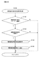
次に、図10を参照しながら、本実施形態における減速形状の作用を説明する。まず、本実施形態のように、センター役物A1−3の一部として減速形状A1−3aが一体成型されて構成されている場合、センター役物A1−3を遊技板A1−1に組み付ける作業のみで、右打ちルートを流下する遊技球を減速する部材が設けられることとなる。即ち、前述したような組み付け誤差を抑制することが可能となり、減速形状A1−3aの通路幅w2は、遊技機毎の個体差が発生し難くなる結果、設計時において減速形状の通路幅w2を可能な限り狭いものとすることが可能となる。よって、右打ちルートを通過し減速形状A1−3aへ流入した遊技球は、突起A1−3a−aに接触した遊技球が次の(下流側の)突起A1−3a−b、A1−3a−c、A1−3a−dに安定して誘導される。即ち、遊技球はジグザグ状に流下しながら、これら突起と衝突を繰り返す{図10(b)}ため、減速形状A1−3aを有する右打ちルートを通過した遊技球は、減速形状A1−3aを有しない右打ちルートを通過した遊技球と比較して大きく減速される。その結果、減速形状A1−3a出口に存在する役物等(例えば、センター役物A1−3や電動役物等)に衝突した際の衝撃力を低減することが可能となり、これら役物等の破損率を低減することができるのである。
(Operation related to the characteristic part 1)
Next, the operation of the deceleration shape in the present embodiment will be described with reference to FIG. First, when the deceleration shape A1-3a is integrally formed as a part of the center accessory A1-3 as in the present embodiment, the center accessory A1-3 is assembled to the game board A1-1. Only, the member which decelerates the game ball which flows down the right-handed route will be provided. That is, it becomes possible to suppress the assembly error as described above, and the passage width w2 of the deceleration shape A1-3a is less likely to cause individual differences for each gaming machine. It can be as narrow as possible. Therefore, the game ball that has passed through the right-handed route and has flowed into the deceleration shape A1-3a is the next (downstream) projection A1-3a-b, A1-3a- c, is stably induced to A1-3a-d. That is, the game ball repeatedly collides with these protrusions while flowing in a zigzag shape {FIG. 10 (b)}. Therefore, the game ball that has passed the right-handed route having the deceleration shape A1-3a has the deceleration shape A1-3a. Compared with the game ball that has passed the right-handed route that does not have, it is greatly decelerated. As a result, it becomes possible to reduce the impact force when colliding with an accessory (eg, center accessory A1-3 or electric accessory) existing at the exit of the deceleration shape A1-3a. The breakage rate can be reduced.
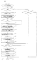
また、センター役物A1−3を遊技板A1−1に組み付け、レール飾りA1−2を遊技板A1−1に組み付ける際には、双方の部材間に間隙(クリアランス)dが生じるよう構成されているため、双方の部材の組み付け誤差を吸収することが可能となり、製品としての品質を向上させることができるのである。更に、双方の部材間に間隙dが生じることは、換言すれば、減速形状A1−3aを形成する右側壁面を別の部材に固定しないように組み付けることで、減速形状A1−3aの右側壁面がレール飾りのみから形成される従来の構成と比較して、部材の揺動を始めとした緩衝効果が得られることを意味する{図10(a)}。より具体的には、間隙dを設けることにより、減速形状A1−3a(特に右壁部)に遊技球が衝突した際、当該間隙dがクッションとして機能し、大きな緩衝効果を発揮するため、より安定して遊技球を減速させることが可能となる。尚、前述のように、本実施形態に係る減速形状A1−3aは、左壁面と右壁面とが一体成型により形成されているため、これらの組み付けは、通路幅w2に影響を与えることなく任意で行うことが可能である。そのため、減速形状A1−3aの開始端である減速形状A1−3aの右壁面の略最上端部において、当該右壁面に設けられた突起A1−3a−aとレール飾りA1−2との略当接部に、微小に隙間を存在させる、又は当該隙間を排除し可能な限り密着させる、といった微調整を行うことが可能である(当該略当接部を密着構造とした場合には、減速形状A1−3aの右壁面の最上端に遊技球が衝突し難くなるため、減速形状A1−3aに余剰な衝撃が加わらず破損が生じる可能性が低くなる一方、当該略当接部に適度な隙間を設けるよう構成した場合には、当該隙間がクッションとして機能し、緩衝効果が発揮されることとなる)。更に、本実施形態において右打ちルートを流下する遊技球は、レール飾りA1−2側壁面(右側壁面)に沿って落下し得る。その結果、減速形状A1−3aを通過する遊技球は、減速形状A1−3aの右壁面に設けられた、最上部に存在する突起A1−3a−aの、特に強度が高い箇所である根元部に安定して衝突し易くなる。従って、大量の遊技球が速い速度で減速形状A1−3aに流入した際にも、突起A1−3a−aが破損する可能性は低くなることを補足しておく。 Further, when the center accessory A1-3 is assembled to the game board A1-1 and the rail decoration A1-2 is assembled to the game board A1-1, a gap (clearance) d is formed between both members. Therefore, it is possible to absorb assembly errors of both members and improve the quality as a product. Furthermore, the gap d is generated between the two members. In other words, the right side wall surface of the deceleration shape A1-3a is assembled so that the right side wall surface forming the deceleration shape A1-3a is not fixed to another member. This means that a buffering effect such as swinging of the member can be obtained as compared with the conventional configuration formed only from the rail decoration {FIG. 10 (a)}. More specifically, by providing the gap d, when the game ball collides with the deceleration shape A1-3a (particularly the right wall portion), the gap d functions as a cushion and exhibits a large cushioning effect. It becomes possible to decelerate the game ball stably. As described above, in the deceleration shape A1-3a according to the present embodiment, the left wall surface and the right wall surface are formed by integral molding, so that these assembly are arbitrary without affecting the passage width w2. Can be done. Therefore, at the substantially uppermost end portion of the right wall surface of the deceleration shape A1-3a, which is the starting end of the deceleration shape A1-3a, the protrusion A1-3a-a provided on the right wall surface and the rail decoration A1-2 are substantially aligned. It is possible to make fine adjustments such that there is a minute gap at the contact portion, or close contact as much as possible (if the substantially contact portion has a close contact structure, a deceleration shape Since it becomes difficult for the game ball to collide with the uppermost end of the right wall surface of A1-3a, there is less possibility of damage caused by excessive impact on the deceleration shape A1-3a. When the structure is provided, the gap functions as a cushion and exhibits a buffering effect). Furthermore, in this embodiment, the game ball flowing down the right-handed route can fall along the rail decoration A1-2 side wall surface (right wall surface). As a result, the game ball passing through the deceleration shape A1-3a is a root portion of the protrusion A1-3a-a that is provided on the right wall surface of the deceleration shape A1-3a and has a particularly high strength. It becomes easy to collide stably. Therefore, it is supplemented that the possibility that the protrusion A1-3a-a is damaged even when a large amount of game balls flow into the deceleration shape A1-3a at a high speed.
尚、本実施形態における減速形状A1−3aに設けられた各突起の形状が、突起の根元部と突起設置面とが成す角度が比較的浅い形状(例えば、略三角形状)である場合には、遊技球から突起面に分散される衝撃が小さくなる。その結果、減速形状を通過する遊技球への減速効果が低くなると考えられる。更に、突起の形状が、突起の根元部分と突起設置面とのなす角が直角に近い形状(例えば、かまぼこ形状)である場合は、遊技球から突起面に分散される衝撃が大きくなる。その結果、減速形状を通過する遊技球への減速効果が
高くなると考えられる。このように、突起の形状を変更することにより、減速形状を通過した後の遊技球の速度を様々に調整することが可能となるが、減速形状A1−3aが鉛直方向を基準として傾きを有している場合、過剰に減速効果を高めることにより、球詰まりの原因になる恐れがある。よって、これら突起の形状は、当該傾きの度合いを考慮して決定する必要があることを補足しておく。
In addition, when the shape of each protrusion provided in the deceleration shape A1-3a in this embodiment is a relatively shallow shape (for example, a substantially triangular shape) formed by the base of the protrusion and the protrusion installation surface. The impact distributed from the game ball to the projecting surface is reduced. As a result, it is considered that the deceleration effect on the game ball passing through the deceleration shape is reduced. Furthermore, when the shape of the protrusion is a shape in which the angle formed by the root portion of the protrusion and the protrusion installation surface is close to a right angle (for example, a kamaboko shape), the impact distributed from the game ball to the protrusion surface increases. As a result, it is considered that the deceleration effect on the game ball passing through the deceleration shape is enhanced. As described above, by changing the shape of the protrusion, the speed of the game ball after passing through the deceleration shape can be variously adjusted. However, the deceleration shape A1-3a has an inclination with respect to the vertical direction. If this is the case, excessively increasing the deceleration effect may cause clogging of the balls. Therefore, it is supplemented that the shape of these protrusions needs to be determined in consideration of the degree of the inclination.
(特徴部分1のまとめ)
以上のように、本実施形態に係る減速形状A1−3aは、左壁面と右壁面とが一体成型により形成されているため、当該減速形状の両壁を一体成型とすることで、当該減速形状A1−3aを形成する右壁面と左壁面の組み付け誤差を小さくすることが可能となる。よって、減速形状の通路幅w2を可能な限り狭いものとすることが可能となり、減速形状A1−3a内の各突起と遊技球を安定して衝突させることができ、遊技球への安定した減速効果を期待出来ることとなる。
(Summary of feature 1)
As described above, the deceleration shape A1-3a according to the present embodiment is formed by integrally molding the left wall surface and the right wall surface, so that the deceleration shape can be obtained by integrally molding both walls of the deceleration shape. Assembling errors between the right wall surface and the left wall surface forming A1-3a can be reduced. Therefore, it becomes possible to make the passage width w2 of the deceleration shape as narrow as possible, the projections in the deceleration shape A1-3a and the game ball can be stably collided, and stable deceleration to the game ball The effect can be expected.
(特徴部分2に係る課題)
次に、図11を参照しながら、従来技術におけるスライド式アタッカー{遊技者側に対して進退可能に構成された蓋部材を設け、当該蓋部材を進出位置に変位させることで箱状部材の開口部(及び連通した入球口)を閉状態とする一方、当該蓋部材を退出位置に変位させることで当該箱状部材の開口部(及び連通した入球口)を開状態とするタイプの大入賞口}に係る問題点を説明する。一般的なスライド式アタッカーは、スライド式アタッカー可変部材A1−4−3−1−1が閉位置にある場合、箱状部材A1−4−2内及び大入賞部A1−4aに遊技球が入球不能又は入球困難な状態となり、スライド式アタッカー可変部材A1−4−3−1−1上を遊技球が転動可能となる。即ち、スライド式アタッカー可変部材A1−4−3−1−1は、スライド式アタッカー可変部材A1−4−3−1−1へ流下する遊技球の着地箇所及び/又は遊技球を転動通路A1−4−2bへ誘導する部材として機能する{図11(a)}。ここで、補助遊技始動口A1−4−4及び大入賞口入賞部A1−4aの位置関係は、周辺部材の大きさや配置によって制限されるため、遊技釘(不図示)を始めとする、遊技球を減速させる機能を有する部材を、スライド式アタッカー可変部材A1−4−3−1−1の直上にて十分数設置することが困難な場合があり、スライド式アタッカー可変部材A1−4−3−1−1へ誘導される遊技球の速度を充分に減速させることが困難となる場合がある。例えば、本例に示されるような構成(配置)の場合、遊技球が速い速度を保ったままスライド式アタッカー可変部材A1−4−3−1−1に衝突することに起因して、スライド式アタッカー可変部材A1−4−3−1−1の破損率が高まるという問題があった。
(Problems related to feature 2)
Next, referring to FIG. 11, a slide-type attacker in the prior art {provided with a lid member configured to be able to advance and retract with respect to the player side, and opening the box-shaped member by displacing the lid member to the advanced position The type (and the entrance hole that communicated) is closed, while the lid member is displaced to the exit position to open the opening of the box-like member (and the entry hole that communicates). The problems relating to the winning prize} will be described. In a general slide-type attacker, when the slide-type attacker variable member A1-4-3-1-1 is in the closed position, a game ball enters the box-shaped member A1-4-2 and the big winning portion A1-4a. It becomes a state where it is impossible to enter or difficult to enter, and the game ball can roll on the slide-type attacker variable member A1-4-3-1-1. That is, the slide-type attacker variable member A1-4-3-1-1 moves the landing point and / or the game ball flowing down to the slide-type attacker variable member A1-4-3-1-1 in the rolling path A1. It functions as a member for guiding to -4-2b {FIG. 11 (a)}. Here, since the positional relationship between the auxiliary game start opening A1-4-4 and the grand prize winning section A1-4a is limited by the size and arrangement of the peripheral members, games such as game nails (not shown) are included. It may be difficult to install a sufficient number of members having a function of decelerating the sphere directly above the slide-type attacker variable member A1-4-3-1-1, and the slide-type attacker variable member A1-4-3 may be difficult to install. It may be difficult to sufficiently reduce the speed of the game ball guided to 1-1-1. For example, in the case of the configuration (arrangement) as shown in this example, the sliding ball is caused by the game ball colliding with the sliding attacker variable member A1-4-3-1-1 while maintaining a high speed. There was a problem that the damage rate of the attacker variable member A1-4-3-1-1 increased.
次に、スライド式アタッカー可変部材A1−4−3−1−1が開位置にある場合には、箱状部材A1−4−2に遊技球が流入し得る状態となる{図11(b)}。ここで、箱状部材A1−4−2に流入した遊技球の着地面である、箱状部材に設けられた遊技球着地面A1−4−2aと、箱状部材A1−4−2の開口部との間には、ある程度の高さがある。更に、前述のように、箱状部材A1−4−2に誘導される遊技球は速い速度で落下し得るため、遊技球の跳ね上がりの高さが高くなる。そして、従来のスライド式アタッカーでは、少なくとも遊技球着地面A1−4−2aの底面は平板状であったがため、速い速度で遊技球着地面A1−4−2aに着地し高く跳ね上がった遊技球が、箱状部材A1−4−2から飛び出してしまうという問題があった。また、従来の箱状部材A1−4−2においては、箱状部材A1−4−2の底面において、遊技球着地面A1−4−2aを含む大入賞口入賞部A1−4aへの誘導路が平板上であったがため、複数の遊技球が箱状部材A1−4−2に流入した際、平面状に敷き詰められるように遊技球が並び、球ガミや球詰まりが発生するという問題があった{図11(c)}。 Next, when the sliding-type attacker variable member A1-4-3-1-1 is in the open position, the game ball can flow into the box-shaped member A1-4-2 {FIG. 11 (b). }. Here, the game ball landing A1-4-2a provided on the box-shaped member, which is the landing of the game ball flowing into the box-shaped member A1-4-2, and the opening of the box-shaped member A1-4-2 There is a certain height between the parts. Furthermore, as described above, since the game ball guided to the box-shaped member A1-4-2 can fall at a high speed, the height of the game ball jumping increases. In the conventional slide-type attacker, since at least the bottom surface of the game ball landing surface A1-4-2a is flat, the game ball landed on the game ball landing surface A1-4-2a at a high speed and jumped high. However, there existed a problem of jumping out from box-shaped member A1-4-2. In addition, in the conventional box-shaped member A1-4-2, a guide path to the big winning opening winning portion A1-4a including the game ball landing surface A1-4-2a on the bottom surface of the box-shaped member A1-4-2. However, when a plurality of game balls flow into the box-shaped member A1-4-2, the game balls are arranged so as to be spread in a flat shape, and there is a problem that ball stagnation or ball clogging occurs. There was {FIG. 11 (c)}.
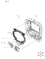
(特徴部分2に係る構成1)
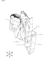
次に、図12を参照しながら、本実施形態に係るスライド式アタッカーユニットA1−4の構成について説明する。スライド式アタッカーユニットA1−4は、スライド式アタッカー開閉機構A1−4−3、前飾り一体部材A1−4−1、箱状部材A1−4−2、転動通路A1−4−2b、一般入賞口A1−4−5及び補助遊技始動口A1−4−4で構成されている。より具体的には、前飾り一体部材A1−4−1の前面に箱状部材A1−4−2が設けられ、更に前飾り一体部材A1−4−1の後ろにスライド式アタッカー開閉機構A1−4−3が設けられている。箱状部材A1−4−2の左上端部には、転動通路A1−4−2bが設けられている。また、前飾り一体部材A1−4−1の左下部には、一般入賞口A1−4−5を含む部材が設けられ、前飾り一体部材A1−4−1の右上部には、補助遊技始動口A1−4−4を含む部材が後面から設けられることで、スライド式アタッカーユニットA1−4が構成されている。これらの部材は、ネジ留め及び/又は嵌め込み加工等によって一体となっている。尚、本構成はあくまで一例であり、部材点数(特に、始動口や入賞口の有無)、各部材の形状や配置位置及び大きさ等は、本構成には何ら限定されず、例えば、水平方向において転動通路A1−4−2bと隣接していない側の箱状部材A1−4−2の上端(右上端)にて、箱状部材A1−4−2へ遊技球を誘導する通路となるような部材を別途配置してもよい(箱状部材A1−4−2への誘導路を別途設けるとの趣旨)。
(
Next, the configuration of the sliding attacker unit A1-4 according to the present embodiment will be described with reference to FIG. The slide-type attacker unit A1-4 includes a slide-type attacker open / close mechanism A1-4-3, a front decoration integrated member A1-4-1, a box-shaped member A1-4-2, a rolling passage A1-4-2b, and a general prize. It consists of a mouth A1-4-5 and an auxiliary game starting mouth A1-4-4. More specifically, a box-shaped member A1-4-2 is provided on the front surface of the front ornament integrated member A1-4-1, and a slide-type attacker opening / closing mechanism A1- is provided behind the front ornament integrated member A1-4-1. 4-3 is provided. A rolling passage A1-4-2b is provided at the upper left end of the box-shaped member A1-4-2. In addition, a member including a general prize opening A1-4-5 is provided at the lower left portion of the front ornament integrated member A1-4-1, and an auxiliary game start is provided at the upper right portion of the front ornament integrated member A1-4-1. The slide type attacker unit A1-4 is configured by providing the member including the mouth A1-4-4 from the rear surface. These members are integrated by screwing and / or fitting. Note that this configuration is merely an example, and the number of members (particularly, the presence or absence of a start opening or a prize opening), the shape, arrangement position, size, and the like of each member are not limited to this configuration. For example, the horizontal direction In the upper end (upper right end) of the box-shaped member A1-4-2 on the side not adjacent to the rolling path A1-4-2b, the game ball is guided to the box-shaped member A1-4-2. Such a member may be separately arranged (the purpose of providing a separate guide path to the box-shaped member A1-4-2).
次に、図13を参照しながら、本実施形態に係る遊技球着地面A1−4−2aを含む箱状部材A1−4−2の構成を説明する。少なくとも遊技球着地面A1−4−2aを含む箱状部材の底面は、箱状部材A1−4−2における遊技盤側の側面との角度が鋭角となる、換言すれば、球体が静止し得る仮想平面を基準として角度c1分だけ、当該底面が後下方向へ沈み込むように傾斜している。ここで、本実施形態では、箱状部材における遊技盤側の側面と、遊技球着地面と、が成す傾斜角度は約80度(角度c1=10度)であるが、当該傾斜角度には何ら限定されない。また、スライド式アタッカー可変部材A1−4−3−1−1と遊技球着地面A1−4−2aとの距離は、遊技球2〜3個分であるが、当該距離には何ら限定されない。更に、箱状部材A1−4−2の奥行(遊技球着地面A1−4−2aの前後幅)は、少なくとも遊技球1個分よりも大きく好適には遊技球1〜2個分であるが、これに限定されるわけではない。更に、少なくとも遊技球着地面A1−4−2aを含む箱状部材A1−4−2の底面及び壁面には、溝や段差c2等が設けられている。尚、本実施形態における箱状部材A1−4−2のように方形形状であることには限定されず、特に、箱状部材の開口部と遊技球着地面A1−4−2aとの距離や、遊技者側の壁面の高さ、遊技球着地面A1−4−2aを含む底面の奥行等を自由に変更可能である。また、本実施形態に係る箱状部材A1−4−2に設けられた溝や段差構造の、配置、形状及び設置数等は、本実施形態には何ら限定されない。更に、少なくとも遊技球着地面A1−4−2aを含む箱状部材A1−4−2の底面の材質は、合成樹脂のみに限定されず、合成樹脂以外の材質、例えばゴム等を合わせて用いる態様も考えられる。例えば、少なくとも遊技球着地面A1−4−2aを含む箱状部材A1−4−2の底面の少なくとも一部を、合成樹脂以外の材質、例えばゴム等で形成してもよい。また、当少なくとも遊技球着地面A1−4−2aを含む箱状部材A1−4−2の底面の下部や肉厚内に、ゴム及び/又はその他の異種材質を埋めこんだり、ゴム及び/又はその他の異種材質の層を挟み込むように配してもよい。 Next, the configuration of the box-shaped member A1-4-2 including the game ball landing surface A1-4-2a according to the present embodiment will be described with reference to FIG. The bottom surface of the box-shaped member including at least the game ball landing surface A1-4-2a has an acute angle with the side surface of the box-shaped member A1-4-2 on the game board side. In other words, the sphere can be stationary. The bottom surface is inclined with respect to the virtual plane by an angle c1 so that the bottom surface sinks downward. Here, in this embodiment, the inclination angle formed by the side surface of the box-shaped member on the game board side and the landing on the game ball is about 80 degrees (angle c1 = 10 degrees). It is not limited. Further, the distance between the slide-type attacker variable member A1-4-3-1-1 and the game ball landing surface A1-4-2a is two to three game balls, but is not limited to the distance. Further, the depth of the box-shaped member A1-4-2 (the front-rear width of the game ball landing surface A1-4-2a) is larger than at least one game ball, and preferably one or two game balls. However, it is not limited to this. Further, a groove, a step c2 and the like are provided on the bottom surface and the wall surface of the box-shaped member A1-4-2 including at least the game ball landing surface A1-4-2a. In addition, it is not limited to having a rectangular shape like the box-shaped member A1-4-2 in the present embodiment, in particular, the distance between the opening of the box-shaped member and the game ball landing surface A1-4-2a The height of the wall surface on the player side, the depth of the bottom surface including the game ball landing surface A1-4-2a, and the like can be freely changed. Moreover, arrangement | positioning, a shape, the number of installation, etc. of the groove | channel and level | step difference structure provided in box-shaped member A1-4-2 which concern on this embodiment are not limited at all to this embodiment. Furthermore, the material of the bottom surface of the box-shaped member A1-4-2 including at least the game ball landing surface A1-4-2a is not limited to the synthetic resin, and a mode in which a material other than the synthetic resin, such as rubber, is used in combination. Is also possible. For example, at least a part of the bottom surface of the box-shaped member A1-4-2 including at least the game ball landing surface A1-4-2a may be formed of a material other than synthetic resin, such as rubber. Further, rubber and / or other dissimilar materials are embedded in the lower part or thickness of the bottom surface of the box-shaped member A1-4-2 including at least the game ball landing surface A1-4-2a, or rubber and / or You may arrange | position so that the layer of another different material may be inserted | pinched.
(特徴部分2に係る作用1)
次に、図14を参照しながら、本実施形態に係る、箱状部材A1−4−2の底面の作用について説明する。前述のように、箱状部材A1−4−2の底面の一部である遊技球着地面A1−4−2aは、箱状部材A1−4−2における遊技盤側の側面との角度が鋭角となるように傾斜している。このような構成のため、箱状部材A1−4−2に落下した遊技球は、傾斜を持つ遊技球着地面A1−4−2aに接触し、遊技球の跳ね上がり方向が後上方向へ転向される。その結果、遊技球の予想外の跳ね上がりにより箱状部材A1−4−2か
ら遊技球が飛び出すことを抑制することが可能となるため、箱状部材A1−4−2へ流入した遊技球が大入賞口入賞部A1−4a側へ誘導されないという、遊技者に不利益を与えてしまう事態を防止することが可能となる。
(
Next, the operation of the bottom surface of the box-shaped member A1-4-2 according to the present embodiment will be described with reference to FIG. As described above, the game ball landing surface A1-4-2a which is a part of the bottom surface of the box-shaped member A1-4-2 has an acute angle with the side surface of the box-shaped member A1-4-2 on the game board side. It is inclined to become. Due to such a configuration, the game ball dropped on the box-shaped member A1-4-2 comes into contact with the game ball landing surface A1-4-2a having an inclination, and the jumping-up direction of the game ball is turned backward and upward. The As a result, it is possible to prevent the game ball from jumping out of the box-shaped member A1-4-2 due to an unexpected jump of the game ball, so that the game ball flowing into the box-shaped member A1-4-2 is large. It is possible to prevent a situation in which a player is disadvantaged that the prize is not guided to the prize winning section A1-4a.
更に、図15を参照しながら、本実施形態に係る、箱状部材A1−4−2の底面のもう一つの作用について説明する。前述のように、本実施形態では、箱状部材A1−4−2の底面の一部である遊技球着地面A1−4−2aは、箱状部材A1−4−2における遊技盤側の側面との角度が鋭角となるように傾斜していることに加え、当該底面には段差c2が設けられている。これにより、箱状部材A1−4−2に導入された遊技球が、当該傾斜に沿って1列に並び易くなることに加え、段差c2によって、ある遊技球と当該ある遊技球に後続する遊技球との重心が上下方向にずれることとなる。その結果、箱状部材A1−4−2aの底面にて平面的に遊技球が詰まることを防止出来ることに加え、高い位置に存在する遊技球が低い位置に存在する遊技球を押し出すため、球ガミや球詰まりを顕著に防止することが可能となる。 Further, another operation of the bottom surface of the box-shaped member A1-4-2 according to the present embodiment will be described with reference to FIG. As described above, in the present embodiment, the game ball landing surface A1-4-2a, which is a part of the bottom surface of the box-shaped member A1-4-2, is the side surface of the box-shaped member A1-4-2 on the game board side. In addition, the bottom surface is provided with a step c2. As a result, the game balls introduced into the box-shaped member A1-4-2 are easily arranged in a line along the inclination, and a game ball and a game game following the game ball are caused by the step c2. The center of gravity with the sphere will shift in the vertical direction. As a result, in addition to preventing the game ball from being clogged in a planar manner at the bottom surface of the box-shaped member A1-4-2a, the game ball present at a high position pushes out the game ball present at a low position. It becomes possible to remarkably prevent clogging and ball clogging.
(特徴部分2に係る構成2)
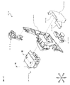
次に、図16を参照しながら、スライド式アタッカー開閉機構A1−4−3の構成に関して説明する。スライド式アタッカー開閉機構A1−4−3は、裏箱前部A1−4−3−2a、裏箱後部A1−4−3−2b、スライド式アタッカー可変部材A1−4−3−1−1及びソレノイド駆動機構A1−4−3−1−2から形成されるスライド式アタッカー可動部A1−4−3−1から構成されている。ここで、裏箱前部A1−4−3−2aの開口内部には、スライド式アタッカー可動部A1−4−3−1に設けられたスライド式アタッカー可変部材A1−4−3−1−1が挿入される。また、スライド式アタッカー可動部A1−4−3−1のソレノイド駆動機構A1−4−3−1−2を後ろから覆うように、裏箱後部A1−4−3−2bを裏箱前部A1−4−3−2aに嵌め込み、スライド式アタッカー可動部A1−4−3−1を固着して構成されている。
(
Next, the configuration of the slide-type attacker opening / closing mechanism A1-4-3 will be described with reference to FIG. The sliding-type attacker opening / closing mechanism A1-4-3 includes a back box front part A1-4-3-2a, a back box rear part A1-4-3-2b, a slide type attacker variable member A1-4-3-1-1 and It is composed of a slide-type attacker movable part A1-4-3-1 formed from a solenoid drive mechanism A1-4-3-1-2. Here, inside the opening of the back box front portion A1-4-3-2a, a slide-type attacker variable member A1-4-3-1-1 provided in the slide-type attacker movable portion A1-4-3-1. Is inserted. Further, the back box rear part A1-4-3-2b is covered with the back box front part A1 so as to cover the solenoid drive mechanism A1-4-3-1-2 of the sliding-type attacker movable part A1-4-3-1 from behind. -4-3-3-2a, and a sliding-type attacker movable part A1-4-3-1 is fixedly configured.
次に、図17を参照しながら、スライド式アタッカー可動部A1−4−3−1の可動態様に関して説明する。前述のように、スライド式アタッカー可動部A1−4−3−1は、スライド式アタッカー可変部材A1−4−3−1−1及びソレノイド駆動機構A1−4−3−1−2から構成されている。更に、ソレノイド駆動機構A1−4−3−1−2は、ソレノイドA1−4−3−1−2a、中間駆動材前部A1−4−3−1−2c及び中間駆動材後部A1−4−3−1−2bから構成されている。ここで、中間駆動材前部A1−4−3−1−2cと中間駆動材後部A1−4−3−1−2bとが接続されており、ソレノイドA1−4−3−1−2aから突き出したロッド形状(ソレノイドロッド)が中間駆動材後部A1−4−3−1−2bと接続され、ソレノイド駆動機構A1−4−3−1−2が一体となって連動する。また、中間駆動材前部A1−4−3−1−2cには上部が解放された持ち手が設けられ、当該持ち手を介して、スライド式アタッカー可変部材A1−4−3−1−1に設けられた棒状部品と接続され、ソレノイド駆動機構A1−4−3−1−2とスライド式アタッカー可変部材A1−4−3−1−1が一体となっている。ソレノイドA1−4−3−1−2aの非励磁状態/励磁状態に合わせてソレノイドロッドが前後駆動し、当該前後駆動力が中間駆動材後部A1−4−3−1−2bに伝達される。当該駆動力により、中間駆動材後部A1−4−3−1−2bと接続された、中間駆動材前部A1−4−3−1−2cに設けられた持ち手が前後駆動し、更にスライド式アタッカー可変部材A1−4−3−1−1の棒状部品を介してスライド式アタッカー可変部材A1−4−3−1−1に当該前後駆動力が伝達され、スライド式アタッカー可変部材A1−4−3−1−1が前後駆動する。 Next, the movable mode of the sliding-type attacker movable unit A1-4-3-1 will be described with reference to FIG. As described above, the slide-type attacker movable part A1-4-3-1 is configured by the slide-type attacker variable member A1-4-3-1-1 and the solenoid drive mechanism A1-4-3-1-2. Yes. Further, the solenoid drive mechanism A1-4-3-1-2 includes a solenoid A1-4-3-1-2a, an intermediate drive material front part A1-4-3-1-2c, and an intermediate drive material rear part A1-4-. It is composed of 3-1-2b. Here, the intermediate drive material front part A1-4-3-1-2c and the intermediate drive material rear part A1-4-3-1-2b are connected and protrude from the solenoid A1-4-3-1-2a. The rod shape (solenoid rod) is connected to the intermediate drive material rear part A1-4-3-1-2b, and the solenoid drive mechanism A1-4-3-1-2 is integrally interlocked. In addition, the intermediate drive member front portion A1-4-3-1-2c is provided with a handle whose upper portion is released, and a slide-type attacker variable member A1-4-3-1-1 is provided via the handle. The solenoid drive mechanism A1-4-3-1-2 and the slide-type attacker variable member A1-4-3-1-1 are integrated with each other. The solenoid rod is driven back and forth in accordance with the non-excited state / excited state of the solenoid A1-4-3-1-2a, and the front and rear driving force is transmitted to the intermediate drive material rear part A1-4-3-1-2b. By the driving force, the handle provided in the intermediate driving material front part A1-4-3-1-2c connected to the intermediate driving material rear part A1-4-3-1-2b is driven back and forth, and further slides. The front-rear driving force is transmitted to the slide-type attacker variable member A1-4-3-1-1 via the rod-shaped part of the variable-type attacker variable member A1-4-3-1-1, and the slide-type attacker variable member A1-4. 3-1-1 drives back and forth.
このように構成されたスライド式アタッカー可動部A1−4−3−1において、スライド式アタッカー可変部材A1−4−3−1−1は、スライド式アタッカー可変部材A1−
4−3−1−1を囲うように設けられた裏箱前部A1−4−3−2aの開口部によって上下左右方向の動きを制限される。ここで、裏箱前部A1−4−3−2aの開口部は、スライド式アタッカー可変部材A1−4−3−1−1の大きさに対して遊びが存在するように設計されている。更に、スライド式アタッカー可変部材A1−4−3−1−1と接続されている中間駆動材前部A1−4−3−1−2cは、スライド式アタッカー可変部材A1−4−3−1−1との接続箇所を形成するパーツが、一部開放されている形状でスライド式アタッカー可変部材A1−4−3−1−1と接続されている。
In the slide-type attacker movable unit A1-4-3-1 configured as described above, the slide-type attacker variable member A1-4-3-1-1 is configured to be a slide-type attacker variable member A1-.
The movement in the vertical and horizontal directions is restricted by the opening of the back box front part A1-4-3-2a provided so as to surround the 4-3-1-1. Here, the opening of the back box front part A1-4-3-2a is designed such that there is play with respect to the size of the slide type attacker variable member A1-4-3-1-1. Further, the intermediate drive member front part A1-4-3-1-2c connected to the slide-type attacker variable member A1-4-3-1-1 is connected to the slide-type attacker variable member A1-4-3-1-1. 1 is connected to the slide-type attacker variable member A1-4-3-1-1 in a partially open shape.
(特徴部分2に係る作用2)
次に、図18を参照しながら、スライド式アタッカー可変部材A1−4−3−1−1の有する緩衝効果について説明する。従来のスライド式可変部材の構成においては、スライド式可変部材が直接ソレノイドと接続され、ソレノイドの前後駆動が直接スライド式可変部材の前後駆動力となっていた。ここで、本実施形態においては、スライド式アタッカー可変部材A1−4−3−1−1は、スライド式アタッカー可変部材A1−4−3−1−1を囲うように設けられた裏箱前部A1−4−3−2aの開口部は、スライド式アタッカー可変部材A1−4−3−1−1の大きさに対して遊び(図中f1)が存在するように設計されている。更に、スライド式アタッカー可変部材A1−4−3−1−1と接続されている中間駆動材前部A1−4−3−1−2cは、スライド式アタッカー可変部材A1−4−3−1−1との接続箇所を形成するパーツが、一部開放(図中f2)されている形状でスライド式アタッカー可変部材A1−4−3−1−1と接続されている。従って、スライド式アタッカー可変部材A1−4−3−1−1が微小に揺動等する場合、中間駆動材前部A1−4−3−1−2cによっては揺動が制限されず、裏箱前部A1−4−3−2aに設計されている遊びの範囲内で上下左右方向に揺動可能な構造となっている。そのため、本実施形態に係るスライド式アタッカー可変部材A1−4−3−1−1は、スライド式アタッカー可変部材A1−4−3−1−1上から流下した遊技球がスライド式アタッカー可変部材A1−4−3−1−1に衝突した際、その衝撃力に合わせてスライド式アタッカー可変部材A1−4−3−1−1自体が揺動することで、当該衝撃力に対する緩衝効果を発揮する。従って、遊技球の落下衝撃によるスライド式アタッカー可変部材A1−4−3−1−1の破損を回避することが可能となる。
(
Next, the buffering effect of the sliding-type attacker variable member A1-4-3-1-1 will be described with reference to FIG. In the configuration of the conventional slide type variable member, the slide type variable member is directly connected to the solenoid, and the longitudinal drive of the solenoid is the front / rear driving force of the direct slide type variable member. Here, in the present embodiment, the slide-type attacker variable member A1-4-3-1-1 has a back box front portion provided so as to surround the slide-type attacker variable member A1-4-3-1-1. The opening of A1-4-3-2a is designed such that there is play (f1 in the figure) with respect to the size of the sliding-type attacker variable member A1-4-3-1-1. Further, the intermediate drive member front part A1-4-3-1-2c connected to the slide-type attacker variable member A1-4-3-1-1 is connected to the slide-type attacker variable member A1-4-3-1-1. 1 is connected to the slide-type attacker variable member A1-4-3-1-1 in a partially open shape (f2 in the drawing). Therefore, when the sliding-type attacker variable member A1-4-3-1-1 swings slightly, the swinging is not limited by the intermediate drive member front part A1-4-3-1-2c. It has a structure that can swing in the vertical and horizontal directions within the range of play designed in the front part A1-4-3-2a. Therefore, the slide-type attacker variable member A1-4-3-1-1 according to this embodiment is configured such that the game ball flowing down from the slide-type attacker variable member A1-4-3-1-1 is a slide-type attacker variable member A1. When it collides with -4-3-1-1, the sliding-type attacker variable member A1-4-3-1-1 itself swings in accordance with the impact force, thereby exhibiting a buffering effect against the impact force. . Therefore, it is possible to avoid damage to the slide-type attacker variable member A1-4-3-1-1 due to the drop impact of the game ball.
尚、図4等に示されるように、本実施形態に係るスライド式アタッカー可変部材A1−4−3−1−1は、水平面に対する傾斜を有する。更に、当該スライド式可変部材と隣接して存在する転動通路A1−4−2bにも同様な傾斜が設けられている。このような構造であるため、スライド式アタッカー可変部材A1−4−3−1−1が略閉位置にある等、遊技球の流路として機能する際、当該スライド式アタッカー可変部材A1−4−3−1−1及び転動通路A1−4−2b上に遊技球が滞留することを防止出来る。尚、本実施形態では、スライド式アタッカー可変部材A1−4−3−1−1及び転動通路A1−4−2bに約10度の傾斜を設けるように構成したが、これには限定されず、当該傾斜の角度は、0度(傾斜なし)〜30度程度まで自由に設定可能である。 In addition, as FIG. 4 etc. show, the slide type | mold attacker variable member A1-4-3-1-1 which concerns on this embodiment has an inclination with respect to a horizontal surface. Furthermore, the same inclination is provided also in rolling passage A1-4-2b which adjoins the said slide type variable member. Because of this structure, when the slide-type attacker variable member A1-4-3-1-1 is functioning as a flow path for a game ball, such as when the slide-type attacker variable member A1-4-3-1-1 is in a substantially closed position, It is possible to prevent the game balls from staying on the 3-1-1 and the rolling passage A1-4-2b. In the present embodiment, the sliding-type attacker variable member A1-4-3-1-1 and the rolling passage A1-4-2b are configured to have an inclination of about 10 degrees. However, the present invention is not limited to this. The inclination angle can be freely set from 0 degrees (no inclination) to about 30 degrees.
(特徴部分2のまとめ)
以上のように、本実施形態では、遊技球着地面A1−4−2aを含む箱状部材の底面は、箱状部材A1−4−2における遊技盤側の側面との角度が鋭角となるように傾斜しているため、箱状部材A1−4−2に落下した遊技球は、傾斜を持つ遊技球着地面A1−4−2aに接触し、遊技球の跳ね上がり方向が後上方向へ転向される。その結果、遊技球の予想外の跳ね上がりにより箱状部材A1−4−2から遊技球が飛び出すことを抑制することが可能となる。加えて、当該底面には段差が設けられているため、箱状部材A1−4−2aの底面にて平面的に遊技球が詰まることを防止出来ることに加え、高い位置に存在する遊技球が低い位置に存在する遊技球を押し出すため、球ガミや球詰まりを顕著に防止することが可能となるのである。そして、スライド式アタッカー可変部材A1−4−3−1−
1が微小に揺動等する場合、中間駆動材前部A1−4−3−1−2cによっては揺動が制限されず、且つ、裏箱前部A1−4−3−2aに設計されている遊びの範囲内で上下左右方向に揺動可能な構造となっているため、遊技球がスライド式アタッカー可変部材A1−4−3−1−1に衝突した際、その衝撃力に対する緩衝効果を発揮することとなる。
(Summary of feature 2)
As described above, in this embodiment, the bottom surface of the box-shaped member including the game ball landing surface A1-4-2a has an acute angle with the side surface of the box-shaped member A1-4-2 on the game board side. Therefore, the game ball that has fallen on the box-shaped member A1-4-2 comes into contact with the slanted game ball landing surface A1-4-2a, and the jumping-up direction of the game ball is turned to the rear upward direction. The As a result, it is possible to prevent the game ball from jumping out of the box-shaped member A1-4-2 due to an unexpected jump of the game ball. In addition, since the bottom surface is provided with a step, it is possible to prevent the game ball from being clogged in a planar manner at the bottom surface of the box-shaped member A1-4-2a, and in addition, there is a game ball present at a high position. Since the game ball present at a low position is pushed out, it becomes possible to remarkably prevent ball bites and ball clogging. And slide type attacker variable member A1-4-3-1-
When 1 is slightly swung, the rocking is not limited by the intermediate drive material front part A1-4-3-1-2c, and the back box front part A1-4-3-2a is designed. Since it has a structure that can swing in the vertical and horizontal directions within the range of play, when the game ball collides with the slide-type attacker variable member A1-4-3-1-1, a buffering effect against the impact force is provided. Will be demonstrated.
(特徴部分3に係る課題)
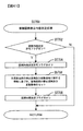
次に、図19を参照しながら、本実施形態における、演出用の可変部材(本例では、所謂シャッター役物)の一般的な動作及び問題点を説明する。まず、本実施形態においては、後述する演出制御処理によって可動するシャッター役物として、シャッター役物左部A2−2L及びシャッター役物右部A2−2Rを備えている。ここで、シャッター役物左部A2−2L及びシャッター役物右部A2−2Rは、退避位置{図19(a)}と、出現位置と{図19(b)}に変位可能に構成されている。尚、本実施形態においては、遊技領域に打ちこまれた遊技球が、シャッター役物左部A2−2L及びシャッター役物右部A2−2Rの可動領域に入り込まないよう構成(例えば、シャッター役物前面にて透明板を設ける等)されており、本来であればシャッター役物の可動領域には遊技球が入り込むことはない。しかしながら、演出装置内に遊技球が侵入することを防ぐために透明な板等を設ける場合、演出の視認性が低下するという問題があるため、当該板状部品を排除した構成が望ましい。しかし、そのような構成とすると、不測の事態、例えば遊技球の想定外の跳ね上がりや遊技盤の整備の際等に、遊技球(エラー球)がシャッター役物左部A2−2L及び/又はシャッター役物右部A2−2Rの可動領域に入り込み、ガイドレール上に乗り上がってしまう場合がある。その場合、シャッター役物左部A2−2L及びシャッター役物右部A2−2Rが退避位置から出現位置へと変位した際等に、シャッター役物左部A2−2L及びシャッター役物右部A2−2R間に遊技球が挟まれ{図19(c)}、シャッター役物の動作が阻害され得る結果、シャッター役物による演出が中断され遊技者の不利益となるだけでなく、シャッター役物に負荷がかかり、シャッター役物が破損してしまう恐れがあった。
(Problems related to feature 3)
Next, with reference to FIG. 19, general operations and problems of a production variable member (a so-called shutter accessory in this example) in the present embodiment will be described. First, in the present embodiment, a shutter accessory left part A2-2L and a shutter accessory right part A2-2R are provided as shutter accessories that can be moved by an effect control process described later. Here, the shutter accessory left portion A2-2L and the shutter accessory right portion A2-2R are configured to be displaceable to a retracted position {FIG. 19 (a)}, an appearance position, and {FIG. 19 (b)}. Yes. In the present embodiment, the configuration is such that the game balls hit in the game area do not enter the movable areas of the shutter accessory left part A2-2L and the shutter accessory right part A2-2R (for example, the shutter accessory A transparent plate is provided on the front surface, etc.), and game balls do not enter the movable region of the shutter accessory. However, when a transparent board or the like is provided in order to prevent the game ball from entering the effect device, there is a problem that the visibility of the effect is lowered. Therefore, a configuration in which the plate-like component is excluded is desirable. However, in such a configuration, the game ball (error ball) is moved to the left part A2-2L of the shutter and / or the shutter in an unexpected situation, for example, when the game ball jumps up unexpectedly or when the game board is maintained. There is a case where it enters the movable region of the right part A2-2R of the accessory and gets on the guide rail. In that case, when the shutter accessory left part A2-2L and the shutter accessory right part A2-2R are displaced from the retracted position to the appearance position, the shutter accessory left part A2-2L and the shutter accessory right part A2- A game ball is sandwiched between 2Rs {FIG. 19 (c)}, and as a result of the action of the shutter object being hindered, the production by the shutter object is interrupted, which not only disadvantages the player, but also to the shutter object. There was a risk that the shutter would be damaged due to the load.
(特徴部分3に係る構成)
次に、図20を参照しながら、本実施形態に係る、演出装置A2の組み付けを説明する。尚、本図では、シャッター役物に係る演出装置を図示し、液晶等のその他の演出装置は不図示である。まず、本実施形態に係る演出装置A2は、遊技盤枠A2−1にシャッターユニットA2−2を設け、更に当該シャッターユニットA2−2の上からカバー部材下部A2−1−1a、カバー部材前部A2−1−1b及びカバー部材前部A2−1−1cを遊技盤枠A2−1に組み付けるように設けることで、構成されている。
(Configuration related to characteristic part 3)
Next, assembly of the rendering device A2 according to the present embodiment will be described with reference to FIG. In the drawing, an effect device related to the shutter accessory is illustrated, and other effect devices such as a liquid crystal are not shown. First, the rendering device A2 according to the present embodiment is provided with a shutter unit A2-2 on the game board frame A2-1, and further, the cover member lower part A2-1-1a and the cover member front part from above the shutter unit A2-2. It is configured by providing A2-1-1b and a cover member front part A2-1-1c so as to be assembled to the game board frame A2-1.
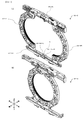
次に、図21(a)及び(b)を参照しながら、本実施形態に係る、シャッターユニットA2−2の構成を説明する。まず、本実施形態に係るシャッターユニットA2−2は、ガイドレールA2−2d、シャッター役物左部A2−2L、シャッター役物右部A2−2R、ギアボックスA2−2u、モーター(不図示)、ピニオンギア(不図示)等によって構成されている。ここで、ガイドレールA2−2dがシャッター役物左部A2−2Lの下部及びシャッター役物右部A2−2Rの下部を挟み込むように組み付けられ、シャッター役物左部A2−2L及びシャッター役物右部A2−2Rが左右変位可能に略固定されている。また、ガイドレールA2−2dの略中心部には、遊技球1個分以上の径であるエラー球排出口左部A2−2d−L及びエラー球排出口右部A2−2d−Rが隔壁wで分断される形で設けられている。尚、隔壁wは、シャッター役物左部A2−2L及び/又はシャッター役物右部A2−2Rの、最大変位位置を制限するストッパーとして好適に作用するが、当該形態に何ら限定されるものではない。更に、エラー球排出口左部A2−2d−L、エラー球排出口右部A2−2d−R及びガイドレールA2−2d等の構成も、当該形態には何ら限定されるものではない(例えば、ガイドレールは左右方向に分断可能な形状であってもよい)。そして、シャッター役物左部A2−2L及びシャッター役物右部A2−2
Rの上部を挟み込むようにギアボックスA2−2uが組み付けられ、シャッター役物左部A2−2L及びシャッター役物右部A2−2Rが左右変位可能に略固定されている。また、シャッター役物左部A2−2L及びシャッター役物右部A2−2Rの上面部には、ラック形状が設けられており、当該ラック形状はギアボックスA2−2uに設けられたギアと当接している。更に、ギアボックスA2−2uの後ろにはモーターが設けられており、ギアボックスA2−2uの空孔を通して、モーターとピニオンギアが接続されている。本実施形態においては、モーターの駆動力により、ピニオンギアが回転駆動し、当該回転駆動力がシャッター役物に設けられたラック形状を介して直線駆動力に変換される。当該駆動力により、シャッター役物左部A2−2L及びシャッター役物右部A2−2Rが、それぞれガイドレールA2−2dの略端部から略中心部の範囲で、退避位置から出現位置まで変位する。
Next, the configuration of the shutter unit A2-2 according to the present embodiment will be described with reference to FIGS. 21 (a) and (b). First, the shutter unit A2-2 according to the present embodiment includes a guide rail A2-2d, a shutter accessory left part A2-2L, a shutter accessory right part A2-2R, a gear box A2-2u, a motor (not shown), It is comprised by the pinion gear (not shown) etc. Here, the guide rail A2-2d is assembled so as to sandwich the lower part of the shutter accessory left part A2-2L and the lower part of the shutter accessory right part A2-2R, and the shutter accessory left part A2-2L and the shutter accessory right part The part A2-2R is substantially fixed so as to be laterally displaceable. In addition, an error ball discharge port left portion A2-2d-L and an error ball discharge port right portion A2-2d-R each having a diameter equal to or larger than one game ball are formed in a substantially central portion of the guide rail A2-2d. It is provided in a form that is divided by. The partition wall w preferably acts as a stopper for limiting the maximum displacement position of the shutter accessory left part A2-2L and / or the shutter accessory right part A2-2R, but is not limited to this form. Absent. Further, the configurations of the error ball discharge port left portion A2-2d-L, the error ball discharge port right portion A2-2d-R, the guide rail A2-2d, and the like are not limited to the form (for example, The guide rail may have a shape that can be divided in the left-right direction). The shutter accessory left part A2-2L and the shutter accessory right part A2-2
The gear box A2-2u is assembled so as to sandwich the upper part of R, and the shutter accessory left part A2-2L and the shutter accessory right part A2-2R are substantially fixed so as to be laterally displaceable. In addition, rack shapes are provided on the upper surfaces of the shutter accessory left part A2-2L and the shutter accessory right part A2-2R, and the rack shape abuts on the gear provided on the gear box A2-2u. ing. Further, a motor is provided behind the gear box A2-2u, and the motor and the pinion gear are connected through a hole in the gearbox A2-2u. In the present embodiment, the pinion gear is rotationally driven by the driving force of the motor, and the rotational driving force is converted into a linear driving force via a rack shape provided in the shutter accessory. By the driving force, the shutter accessory left part A2-2L and the shutter accessory right part A2-2R are displaced from the retracted position to the appearance position in the range from the substantially end part to the substantially central part of the guide rail A2-2d, respectively. .
(特徴部分3に係る作用)
次に、図22〜図24を参照しながら、本実施形態に係るエラー球排出口の作用を説明する。前述のように、ガイドレールA2−2dの略中心部には、エラー球排出口左部A2−2d−L及びエラー球排出口右部A2−2d−Rが設けられている。当該エラー球排出口左部A2−2d−L及びエラー球排出口右部A2−2d−Rは、共にエラー球排出流路(カバー部材下部A2−1−1a内に設けられた遊技球流路)と導通されている、更に、当該エラー球排出流路は、アウト口A1−2aと導通されている。その結果、遊技中に万一、ガイドレールA2−2d上に遊技球がエラー球eとして入り込んで停留していたとしても(図22)、演出発生時等によりシャッター役物左部A2−2L及び/又はシャッター役物右部A2−2Rが退避位置から出現位置(例えば略最大可動位置)へ移動した場合には、当該エラー球はエラー球排出口左部A2−2d−L及び/又はエラー球排出口右部A2−2d−Rへ押し出される(図24)。そして、当該押し出されたエラー球は、エラー球排出口左部A2−2d−L及び/又はエラー球排出口右部A2−2d−Rを通してエラー球排出流路へ流入し、アウト口A1−2aを通し、遊技領域外へと排出される(図23)。従って、遊技球がガイドレールA2−2dに乗り上がった場合であっても、遊技球が当該ガイドレール上に停留しシャッター役物左部A2−2L及び/又はシャッター役物右部A2−2Rの動きを阻害する、といった事態を防止することが可能となる。その結果、シャッター役物の予期せぬ破損を防いだり、遊技者の不利益を回避することが可能となる。また、当該構成では、ガイドレールに乗り上がった遊技球を、遊技を中断することなく排除する機能を有するため、演出装置等の前面に透明な板等を設ける必要がなくなり、従来の構成と比較し、液晶等による演出の視認性を確保することが可能となる。
(Operation related to characteristic part 3)
Next, the operation of the error ball discharge port according to the present embodiment will be described with reference to FIGS. As described above, the error ball discharge port left portion A2-2d-L and the error ball discharge port right portion A2-2d-R are provided at the substantially central portion of the guide rail A2-2d. The error ball discharge port left portion A2-2d-L and the error ball discharge port right portion A2-2d-R are both error ball discharge channels (game ball channels provided in the cover member lower portion A2-1-1a). In addition, the error ball discharge flow path is connected to the out port A1-2a. As a result, even if a game ball enters and stops as an error ball e on the guide rail A2-2d during the game (FIG. 22), the shutter accessory left part A2-2L and When the shutter part right part A2-2R moves from the retracted position to the appearance position (for example, approximately the maximum movable position), the error sphere is the error sphere outlet left part A2-2d-L and / or the error sphere. It is pushed out to the discharge port right part A2-2d-R (FIG. 24). The pushed error sphere flows into the error sphere discharge flow path through the error sphere discharge port left portion A2-2d-L and / or the error sphere discharge port right portion A2-2d-R, and the out port A1-2a. And is discharged out of the gaming area (FIG. 23). Therefore, even when the game ball rides on the guide rail A2-2d, the game ball stops on the guide rail and the shutter accessory left part A2-2L and / or the shutter accessory right part A2-2R It is possible to prevent such a situation that the movement is hindered. As a result, it is possible to prevent the shutter accessory from being unexpectedly damaged and to avoid the disadvantage of the player. In addition, the configuration has a function to eliminate the game ball that has been on the guide rail without interrupting the game, so there is no need to provide a transparent plate or the like on the front surface of the production device, etc. Compared to the conventional configuration In addition, it is possible to ensure the visibility of the performance by the liquid crystal or the like.
(特徴部分3のまとめ)
以上のように、本実施形態では、シャッター役物左部A2−2L及びシャッター役物右部A2−2Rが、それぞれガイドレールA2−2dの略端部から略中心部の範囲で、退避位置から出現位置まで変位するよう構成されている状況下、ガイドレールA2−2dの略中心部には、エラー球排出口左部A2−2d−L及びエラー球排出口右部A2−2d−Rが設けられているため、遊技球がガイドレールA2−2dに乗り上がった場合であっても、遊技球が当該ガイドレール上に停留しシャッター役物左部A2−2L及び/又はシャッター役物右部A2−2Rの動きを阻害する、といった事態を防止することが可能となるのである。
(Summary of feature 3)
As described above, in the present embodiment, the shutter accessory left part A2-2L and the shutter accessory right part A2-2R are each in the range from the substantially end part to the substantially central part of the guide rail A2-2d from the retracted position. Under the condition that the guide rail A2-2d is displaced to the appearance position, an error ball discharge port left portion A2-2d-L and an error ball discharge port right portion A2-2d-R are provided in the substantially central portion of the guide rail A2-2d. Therefore, even when the game ball rides on the guide rail A2-2d, the game ball stops on the guide rail and the shutter accessory left part A2-2L and / or the shutter accessory right part A2 It is possible to prevent such a situation that the movement of -2R is inhibited.
(変更例)
尚、本実施形態は、スライド式アタッカー可変部材が略閉位置にある場合、当該スライド式アタッカー可変部材は遊技球の転動流路として機能するよう構成されている。ここで、当該スライド式アタッカー可変部材上を転動する遊技球の速度が速い場合がある。例えば、スライド式アタッカー可変部材に当接されるように設けられている転動通路等も含めた、スライド式アタッカー可変部材周辺における遊技球の転動流路において、当該転動流
路上を転動する遊技球が停留しないように、当該転動流路に傾斜を設ける場合である。しかし、当該構成においては、当該転動流路の傾斜によって遊技球が加速される可能性がある。このように、遊技球が速い速度でスライド式アタッカー可変部材上や転動通路を転動し得るため、当該遊技球が速い速度を保ったまま役物や遊技釘等に衝突した際、その衝撃力で当該役物等が破損する可能性がある。そこで、このような問題点を回避するための構成を、本実施形態からの変更例とし、以下、本実施形態からの変更点についてのみ詳述する。
(Example of change)
In this embodiment, when the slide-type attacker variable member is in the substantially closed position, the slide-type attacker variable member functions as a rolling flow path for the game ball. Here, the speed of the game ball rolling on the slide-type attacker variable member may be high. For example, in a rolling flow path of a game ball around a sliding attack variable member, including a rolling passage provided so as to be in contact with the sliding attack variable member, it rolls on the rolling flow path. This is a case where the rolling channel is provided with an inclination so that the game ball to be stopped does not stop. However, in the said structure, there exists a possibility that a game ball may be accelerated by the inclination of the said rolling flow path. In this way, the game ball can roll on the sliding attacker variable member and the rolling passage at a high speed, so when the game ball collides with an object or a game nail while maintaining a high speed, the impact There is a possibility of damage to the relevant items by force. Therefore, a configuration for avoiding such a problem will be described as a modified example from the present embodiment, and only the modified points from the present embodiment will be described in detail below.
本変更例は、スライド式アタッカー可変部材及び、スライド式アタッカー可変部材と略当接し且つ遊技球の転動流路となるような部材(例えば転動通路A1−4−2b)に、遊技球を減速させる形状を設けた態様である(以下、当該形状を第2減速形状とする)。遊技球が転動流路上の第2減速形状を転動することで減速されるよう構成されている限り、当該第2減速形状は、その形状、位置、長さ及び減速機構等は何ら限定されるものではない。従って、本変更例に係る第2減速形状は、転動通路A1−4−2bやスライド式アタッカー可変部材A1−4−3−1−1上に第2減速形状を設ける構成が考えられる。他にも、箱状部材の上端(右上端)にて、箱状部材A1−4−2aへ遊技球を誘導する、遊技球の転動流路となるような部材を新たに設け、当該部材上に第2減速形状を設けるような構成が考えられる。更に、当該変更例に係る第2減速形状は、転動流路における遊技球接地面や転動流路の壁面に第2減速形状を設ける構成や、当該転動流路を覆うように新たに遊技球が接する壁面を設け、当該壁面に第2減速形状を設けるような構成が考えられる。また、本変更例に係る第2減速形状は、遊技球が接する面に、突起、溝、段差等を設けることで、当該突起、溝、段差等に遊技球を衝突させることで遊技球を減速させるような構成が考えられる。更に、第2減速形状を形成する壁面の少なくとも一部を、当該第2減速
形状の減速効果を高めるために、合成樹脂以外の材質、例えばゴム等を合わせて用いるような態様も考えられる。例えば、第2減速形状内部に設けた、突起、溝や段差を、合成樹脂以外の材質、例えばゴム等によって形成してもよい。また、当該突起、溝や段差の内部(肉厚内)にゴム及び/又はその他の異種材質を埋めこんだり、当該突起、溝や段差の設置面にゴム及び/又はその他の異種材質の層を挟み込むように配してもよい。
In this modified example, a game ball is placed on a slide-type attacker variable member and a member (for example, the rolling path A1-4-2b) that is substantially in contact with the slide-type attacker variable member and serves as a rolling channel of the game ball. This is a mode in which a shape to be decelerated is provided (hereinafter, this shape is referred to as a second deceleration shape). As long as the game ball is configured to be decelerated by rolling the second deceleration shape on the rolling flow path, the shape, position, length, deceleration mechanism, etc. of the second deceleration shape are not limited. It is not something. Therefore, the 2nd deceleration shape which concerns on this example of a change can consider the structure which provides a 2nd deceleration shape on rolling channel | path A1-4-2b or slide type | mold attacker variable member A1-4-3-1-1. In addition, at the upper end (upper right end) of the box-shaped member, a member that guides the game ball to the box-shaped member A1-4-2a and serves as a rolling flow path for the game ball is newly provided. A configuration in which a second deceleration shape is provided on the top is conceivable. Furthermore, the 2nd deceleration shape which concerns on the said modification is newly provided so that the 2nd deceleration shape may be provided in the game ball | bowl grounding surface in the rolling flow path, or the wall surface of a rolling flow path, and the said rolling flow path may be covered. A configuration is conceivable in which a wall surface that is in contact with the game ball is provided and a second deceleration shape is provided on the wall surface. In addition, the second deceleration shape according to this modified example provides a projection, a groove, a step, etc. on the surface that comes into contact with the game ball, thereby decelerating the game ball by causing the game ball to collide with the projection, groove, step, etc. Such a configuration is conceivable. Furthermore, an aspect in which at least a part of the wall surface forming the second deceleration shape is used in combination with a material other than synthetic resin, such as rubber, in order to enhance the deceleration effect of the second deceleration shape. For example, the protrusions, grooves, and steps provided in the second deceleration shape may be formed of a material other than synthetic resin, such as rubber. Also, rubber and / or other dissimilar materials are embedded in the protrusions, grooves and steps (within the wall thickness), or a layer of rubber and / or other dissimilar materials is placed on the installation surface of the protrusions, grooves and steps. You may arrange so that it may pinch | interpose.
ここで、図25を参照しながら、本変更例に係る第2減速形状の構成の一形態を説明する。本形態における転動通路A1−4−2bには、トンネル構造A1−4−bが設けられ第2減速形状を構成している。当該トンネル構造A1−4−bは、転動通路A1−4−2b、前飾り一体部材A1−4−1及びL字構造体A1−4−6で囲われて形成されている。L字構造体A1−4−6は、略閉位置にあるスライド式アタッカー可変部材A1−4−3−1−1と略当接するように設けられている。L字構造体A1−4−6は、嵌め込み加工及び/又はネジ留め等により、着脱可能に設計されている。L字構造体A1−4−6を転動通路A1−4−2bに設置した際、L字構造体A1−4−6の内側面であり、トンネル構造A1−4−b内部の遊技者側である壁面には、突起A1−4−6bが複数設けられている(図26参照)。尚、L字構造体A1−4−6には、突起ではなく、溝や段差等を設けることにより第2減速形状を成してもよい。また、L字構造体A1−4−6に設けられた、突起A1−4−6bの大きさ、個数、位置及び形状等は本形態に何ら限定されるものではない。また、本形態に係るL字構造体A1−4−6の、長さ、幅、高さ、組み付け方法及び組み付け位置等は、当該トンネル構造A1−4−bを遊技球が転動可能である限り、本形態に何ら限定されるものではない。例えば、箱状部材の上端(右上端)にて、箱状部材A1−4−2aへ遊技球を誘導する、遊技球の転動流路となるような部材を新たに設け、当該部材上にL字構造体A1−4−6を設けてもよい。 Here, an example of the configuration of the second deceleration shape according to this modification will be described with reference to FIG. In the rolling passage A1-4-2b in this embodiment, a tunnel structure A1-4-b is provided to constitute a second deceleration shape. The tunnel structure A1-4-b is formed by being surrounded by a rolling passage A1-4-2b, a front decoration integrated member A1-4-1, and an L-shaped structure A1-4-6. The L-shaped structure A1-4-6 is provided so as to be substantially in contact with the slide-type attacker variable member A1-4-3-1-1 in the substantially closed position. The L-shaped structure A1-4-6 is designed to be detachable by fitting and / or screwing or the like. When the L-shaped structure A1-4-6 is installed in the rolling passage A1-4-2b, it is the inner surface of the L-shaped structure A1-4-6 and the player side inside the tunnel structure A1-4-b A plurality of protrusions A1-4-6b are provided on the wall surface (see FIG. 26). Note that the L-shaped structure A1-4-6 may have a second reduction shape by providing a groove, a step, or the like instead of a protrusion. Further, the size, number, position, shape, and the like of the protrusions A1-4-6b provided in the L-shaped structure A1-4-6 are not limited to this embodiment. Further, the length, width, height, assembling method, assembling position, and the like of the L-shaped structure A1-4-6 according to the present embodiment are such that the game ball can roll on the tunnel structure A1-4-b. As long as it is not limited to this form. For example, at the upper end (upper right end) of the box-shaped member, a member that serves as a rolling flow path for the game ball that guides the game ball to the box-shaped member A1-4-2a is newly provided on the member. An L-shaped structure A1-4-6 may be provided.
次に、図26を参照しながら、本変更例に係る第2減速形状の一形態の作用を説明する。第2減速形状をこのような構成とすることで、転動通路A1−4−2bを通過する遊技球は、トンネル構造A1−4−b内で、突起A1−4−6bや前飾り一体部材側の壁面と
衝突し、減速される。そのため、遊技球の流路において転動通路A1−4−2bの下流に存在する、第2主遊技始動口電動役物を始めとする役物や遊技釘等に衝突する際の、遊技球の衝撃力を緩和することが可能となる。更に、当該L字構造体A1−4−6を着脱可能とすることで、当該L字構造体A1−4−6を着脱したり、L字構造体の構成を変更する等し、遊技球の速度に合わせて減速効果の強弱等を変更することが可能になるという効果を奏する。L字構造体A1−4−6は遊技者の視認性を悪化させるが、当該L字構造体A1−4−6は着脱可能であるため、転動流路を通過する遊技球の速度が速い場合には当該L字構造体A1−4−6を設け、転動流路を通過する遊技球の速度が遅い場合には当該L字構造体A1−4−6を設けないように構成することが好適である。
Next, the operation of one embodiment of the second deceleration shape according to this modification will be described with reference to FIG. By configuring the second deceleration shape as described above, the game ball passing through the rolling passage A1-4-2b can be used as a protrusion A1-4-6b or a front decoration integrated member in the tunnel structure A1-4-b. It collides with the side wall and is decelerated. Therefore, when the game ball collides with an accessory such as a second main game start opening electric accessory or a game nail, which exists downstream of the rolling passage A1-4-2b in the flow path of the game ball, It is possible to reduce the impact force. Further, by making the L-shaped structure A1-4-6 detachable, the L-shaped structure A1-4-6 can be detached, the configuration of the L-shaped structure can be changed, etc. There is an effect that it is possible to change the strength of the deceleration effect according to the speed. Although the L-shaped structure A1-4-6 deteriorates the visibility of the player, since the L-shaped structure A1-4-6 is detachable, the speed of the game ball passing through the rolling flow path is high. In this case, the L-shaped structure A1-4-6 is provided, and when the speed of the game ball passing through the rolling flow path is low, the L-shaped structure A1-4-6 is not provided. Is preferred.
ここで、前述のように、箱状部材内に遊技球が流入する場合、遊技球着地面を箱状部材における遊技盤側の側面との角度が鋭角となるように傾斜させることで、遊技球が遊技球着地面で跳ね上がり転動通路へ飛び出すことを防止出来る(図14参照)。しかし、不測の事態、例えば、既に遊技球着地面に存在している遊技球の上に別の遊技球が落下する等し、当該遊技球が予想外に跳ね上がった場合等には、遊技球が転動通路へ乗り上がる可能性がある。その結果、遊技球が、箱状部材内部に設けられた大入賞口入賞検出装置に誘導されず、転動通路上を転動しアウト口に誘導される等し、遊技者の不利益となる可能性がある。しかし、本形態のように、閉位置にあるスライド式アタッカー可変部材と略当接するように、転動通路にトンネル構造を設ける構成とすることにより、転動通路へ乗り上がるように跳ね上がった遊技球を、トンネル構造の縁に衝突させ、箱状部材内へ押し戻すことが可能となる。即ち、本形態のように第2減速形状を構成することで、遊技球を減速させることで各種部材の長寿命化が可能となるのみならず、遊技者の不利益を軽減することが可能となるという効果を奏する。 Here, as described above, when a game ball flows into the box-shaped member, the game ball landing is inclined so that the angle with the side surface of the box-shaped member on the game board side becomes an acute angle. Can be prevented from jumping up on the game ball landing and jumping out to the rolling path (see FIG. 14). However, in an unforeseen situation, for example, when another game ball falls on the game ball already existing on the game ball landing surface and the game ball jumps up unexpectedly, the game ball There is a possibility of getting on the rolling path. As a result, the game ball is not guided to the big prize opening prize detection device provided inside the box-shaped member, but rolls on the rolling path and is guided to the out mouth, resulting in a disadvantage to the player. there is a possibility. However, as in this embodiment, a game ball that has jumped up so as to ride on the rolling passage is formed by providing a tunnel structure in the rolling passage so as to substantially contact the slide-type attacker variable member in the closed position. Can collide with the edge of the tunnel structure and be pushed back into the box-shaped member. That is, by configuring the second deceleration shape as in this embodiment, it is possible not only to extend the life of various members by decelerating the game ball, but also to reduce the disadvantage of the player. The effect of becoming.
次に、図27のブロック図を参照しながら、本実施形態に係るぱちんこ遊技機の各種機能について説明する。はじめに、主制御装置1000は、遊技に係る遊技周辺機器(第1主遊技周辺機器A、第2主遊技周辺機器B、第1・第2主遊技共用周辺機器C、補助遊技周辺機器D)、演出に係るサブメイン制御部2320(演出表示制御手段2320)、主制御装置1000からの払出指示に基づき所定数の賞球の払出制御を行う賞球払出制御装置3000と、情報伝達可能に接続されている。また、サブメイン制御部2320(演出表示制御手段2320)は、画像演出を実行するサブサブ制御部2310(演出表示手段2310)、各種遊技効果ランプ(例えばサイドランプ)やスピーカ等とも電気的に接続されている。更に、賞球払出制御装置3000は、ステッピングモータやスプロケット等を備えた賞球払出装置と電気的に接続されている。尚、主制御装置1000、サブメイン制御部2320(演出表示制御手段2320)、サブサブ制御部2310(演出表示手段2310)、賞球払出制御装置3000等は、ハードウエア的にはデータやプログラムを格納するROMやRAM、演算処理に用いるCPU等の素子等から構成される。尚、以下で主制御装置1000に含まれるとする各手段を周辺機器(例えば、遊技周辺機器2000)に搭載される形で構成してもよい。例えば、周辺機器(例えば、遊技周辺機器2000)に含まれるとする各手段を主制御装置1000に搭載される形で構成してもよい。以下、上記各手段(装置)の詳細を説明する。
Next, various functions of the pachinko gaming machine according to the present embodiment will be described with reference to the block diagram of FIG. First, the
まず、主制御装置1000は、主遊技(第1主遊技、第2主遊技、特別遊技)・補助遊技・一般遊技に関する主たる制御を司る遊技制御手段1100と、遊技周辺機器2000側に各種遊技情報{例えば、停止図柄情報、停止図柄の属性情報{例えば、15R大当り(出球あり)、2R大当り(出球無し)、小当り、ハズレ}、変動態様に関する情報(例えば、変動時間)、特別遊技の開始信号・状態情報・終了信号、保留情報等}を送信するための情報送信制御手段1300と、各種入賞口への遊技球の入賞に基づき所定の賞球の払出を行うように賞球払出制御装置3000を制御する賞球払出決定手段1400と、を有している。
First, the
ここで、遊技制御手段1100は、各入球口(始動口等)への遊技球の流入を判定するための入球判定手段1110と、各乱数の取得可否を判定し、当該判定結果に基づき当該各乱数を取得するための乱数取得判定実行手段1120と、変動表示中における各始動口への入球を保留球として上限個数以内で一時記憶するための保留制御手段1130と、後述する第1主遊技側乱数・第2主遊技側乱数・補助遊技側乱数に基づき特別遊技の当否及び第2主遊技始動口電動役物2112の開放可否を抽選する当否抽選手段1135と、各乱数に基づき、各図柄の停止図柄及び変動態様(変動時間等)を決定するための図柄内容決定手段1140と、各図柄の変動及び停止表示する制御を行うための表示制御手段1150と、第2主遊技始動口2110の第2主遊技始動口電動役物2112の開閉決定に直接関連する各種処理を行うための電動役物開閉制御手段1160と、通常遊技よりも遊技者に有利な特別遊技に関する制御を司る特別遊技制御手段1170と、第1主遊技及び第2主遊技並びに補助遊技に関し、現在の遊技状態をどの遊技状態に移行させるかの決定と、当該決定に基づき遊技状態を移行させる処理を行うための特定遊技制御手段1180と、現在及び過去の遊技状態[例えば、主遊技に関する状態{通常遊技状態、特定遊技状態(確率変動遊技状態、時間短縮遊技状態、限定頻度遊技状態)、特別遊技状態}、補助遊技に関する状態(易開放状態、非易開放状態)、主遊技図柄や補助遊技図柄に係る停止図柄及び変動態様情報、各種フラグのオンオフ状況、特別遊技中の遊技状態(例えばラウンド数や入賞個数情報)]等を一時記憶するための遊技状態一時記憶手段1190と、を有している。以下、各手段について詳述する。 Here, the game control means 1100 determines whether or not each random number can be acquired by determining whether or not each ball can be acquired, and whether or not the ball determination means 1110 determines whether the game ball flows into each ball entrance (starting port, etc.). Random number acquisition determination execution means 1120 for acquiring each random number, a hold control means 1130 for temporarily storing a ball entering each start port during a variable display as a hold ball within an upper limit number, and a first to be described later On the basis of each random number, a random determination means 1135 for determining whether or not the special game is successful and whether or not the second main game start opening electrical accessory 2112 is open based on the main game side random number, the second main game side random number, and the auxiliary game side random number, Symbol content determination means 1140 for determining the stop symbol and variation mode (variation time, etc.) of each symbol, display control means 1150 for controlling the variation and stop display of each symbol, and the second main game start port 21 0 for controlling the opening / closing of the second main game start opening electric accessory 2112 and the special control for controlling the special game advantageous to the player over the normal game. With respect to the game control means 1170, the first main game, the second main game, and the auxiliary game, a determination as to which game state the current game state is to be transferred to, and a process for changing the game state based on the determination Specific game control means 1180 and current and past game states [for example, states related to the main game {normal game state, specific game state (probability variation game state, time-reduced game state, limited frequency game state), special game state}, State related to auxiliary games (easy-open state, non-easy-open state), stop symbol and variation mode information related to main game symbol and auxiliary game symbol, on / off status of various flags, special game Have the game state temporary storage means 1190 for temporarily storing the game state (eg, the number of rounds and the winning number information) or the like, the. Hereinafter, each means will be described in detail.
まず、入球判定手段1110は、第1主遊技始動口2210(第1主遊技始動口A1−7)へ遊技球が入球したか否かを判定する第1主遊技始動口入球判定手段1111と、第2主遊技始動口2110(第2主遊技始動口A1−8)へ遊技球が入球したか否かを判定する第2主遊技始動口入球判定手段1112と、補助遊技始動口2410(補助遊技始動口A1−4−4)に遊技球が流入したか否かを判定する補助遊技入球口入球判定手段1113とを有している。 First, the entrance determination means 1110 is a first main game start opening entrance determination means for determining whether or not a game ball has entered the first main game start opening 2210 (first main game start opening A1-7). 1111, a second main game start port entrance determining means 1112 for determining whether or not a game ball has entered the second main game start port 2110 (second main game start port A1-8), and an auxiliary game start Auxiliary game entrance entrance entrance judging means 1113 for judging whether or not a game ball has flowed into the mouth 2410 (auxiliary game start entrance A1-4-4) is provided.
次に、乱数取得判定実行手段1120は、第1主遊技始動口2210への遊技球の入球に基づき第1主遊技側乱数を取得するか否かを判定すると共に、判定結果に応じて当該乱数(例えば、第1当選乱数、第1変動態様決定乱数、第1主遊技図柄決定乱数等)を取得する第1主遊技乱数取得判定実行手段1121と、第2主遊技始動口2110への遊技球の入球に基づき第2主遊技側乱数を取得するか否かを判定すると共に、判定結果に応じて当該乱数(例えば、第2当選乱数、第2変動態様決定乱数、第2主遊技図柄決定乱数等)を取得する第2主遊技乱数取得判定実行手段1122と、補助遊技側選乱数の取得の可否を判定し、当該判定結果に基づき当該乱数を取得するための補助遊技乱数取得判定実行手段1123とを有している。 Next, the random number acquisition determination execution means 1120 determines whether or not to acquire the first main game side random number based on the game ball entering the first main game start port 2210, and according to the determination result, A first main game random number acquisition determination execution means 1121 for acquiring random numbers (for example, a first winning random number, a first variation mode determination random number, a first main game symbol determination random number, etc.) and a game to the second main game start port 2110 It is determined whether or not the second main game random number is acquired based on the incoming ball, and the random number (for example, the second winning random number, the second variation mode determining random number, the second main game symbol, etc.) according to the determination result A second main game random number acquisition determination execution unit 1122 for acquiring a determined random number, etc., and determining whether or not the auxiliary game side selection random number can be acquired, and executing an auxiliary game random number acquisition determination for acquiring the random number based on the determination result Means 1123.
ここで、上記を含め本特許請求の範囲及び本明細書における「乱数」は、例えば、乱数の種類(例えば、当選乱数や変動態様決定乱数)により割り振られた「0」〜「65535」や「0」〜「255」といった所定範囲からランダムに選択された値である。また、乱数としては、数学的に発生させる乱数でなくともよく、ハードウエア乱数やソフトウエア乱数等により発生させる擬似乱数でもよい。例えば、乱数にある夫々の値の発現方式が、乱数の数列に沿って順々に値を発現させる方式(プラスワン方式)、乱数の数列の最終値が発現したときの次の値(初期値)を偶然性のある値によって定める方式(初期値更新方式)、これらの組み合わせ等を挙げることができる。 Here, the “random number” in the claims and the present specification including the above is, for example, “0” to “65535” or “random number” assigned according to the type of random number (for example, a winning random number or a variation mode determining random number). It is a value randomly selected from a predetermined range such as “0” to “255”. The random number may not be a mathematically generated random number, but may be a pseudo random number generated by a hardware random number, a software random number, or the like. For example, the expression method of each value in the random number is a method in which the value is expressed in order along the random number sequence (plus one method), the next value when the final value of the random number sequence is expressed (initial value) ) With a contingent value (initial value update method), a combination of these, and the like.
次に、保留制御手段1130は、第1主遊技図柄変動許可が下りていない状況で取得した当該第1主遊技側乱数を一時記憶するか否かを判定し、当該判定結果に基づき前記乱数を図柄変動許可が下りるまで第1主遊技図柄保留情報一時記憶手段1131aに保留する
ための第1主遊技図柄保留手段1131と、第2主遊技図柄変動許可が下りていない状況で取得した当該第2主遊技側乱数を一時記憶するか否かを判定し、当該判定結果に基づき前記乱数を図柄変動許可が下りるまで第2主遊技図柄保留情報一時記憶手段1132aに保留するための第2主遊技図柄保留手段1132と、補助遊技図柄変動許可が下りていない状況で取得した補助遊技側乱数を一時記憶するか否かを判定し、当該判定結果に基づき当該乱数を図柄変動許可が下りるまで補助遊技図柄保留情報一時記憶手段1133aに保留するための補助遊技図柄保留手段1133と、を有している。ここで、第1主遊技図柄保留手段1131、第2主遊技図柄保留手段1132及び補助遊技図柄保留手段1133は、最大4個まで記憶可能な、前記乱数を保留順序と結合した形で一時記憶するための、第1主遊技図柄保留情報一時記憶手段1131a、第2主遊技図柄保留情報一時記憶手段1132a及び補助遊技図柄保留情報一時記憶手段1133aを夫々有している。
Next, the hold control means 1130 determines whether or not to temporarily store the first main game random number acquired in a situation where the first main game symbol variation permission has not been given, and based on the determination result, the random number is determined. The first main game symbol holding means 1131 for holding in the first main game symbol hold information temporary storage means 1131a until the symbol change permission is lowered, and the second acquired in the situation where the second main game symbol change permission is not lowered. It is determined whether or not the main game side random number is temporarily stored, and based on the determination result, the second main game symbol for holding the random number in the second main game symbol hold information temporary storage means 1132a until the symbol variation permission is lowered. It is determined whether or not to temporarily store the holding game 1132 and the auxiliary game side random number acquired in a situation where the auxiliary game symbol variation permission has not been granted, and the random number is reduced based on the determination result. Up has an auxiliary game symbol hold means 1133 for holding the auxiliary game symbol reservation information temporary storage means 1133a, the. Here, the first main game symbol holding means 1131, the second main game symbol holding means 1132 and the auxiliary game symbol holding means 1133 can temporarily store up to four random numbers combined with the holding order. The first main game symbol hold information temporary storage means 1131a, the second main game symbol hold information temporary storage means 1132a, and the auxiliary game symbol hold information temporary storage means 1133a are provided.
次に、当否抽選手段1135は、当否抽選の結果、当りである場合に特別遊技への移行決定をする(例えば、内部的に当りフラグをオンにする)特別遊技移行決定手段1135aと、当否抽選を行う際に参照される当否抽選用テーブル1135bとを、有している。ここで、当否抽選用テーブル1135bは、第1主遊技図柄に関しての当否抽選を行う際に参照される第1主遊技用当否抽選テーブル1135b−1と、第2主遊技図柄に関しての当否抽選を行う際に参照される第2主遊技用当否抽選テーブル1135b−3と、を有している。尚、詳細なテーブル構成の一例については後述する。 Next, the success / failure lottery means 1135 determines whether or not to win a special game if the result of the success / failure lottery is a win (for example, internally turns on the winning flag), and the success / failure lottery means 1135a. And a success / failure lottery table 1135b which is referred to when performing. Here, the success / failure lottery table 1135b performs the first main game success / failure lottery table 1135b-1 referred to when performing the success / failure lottery with respect to the first main game symbol and the second main game symbol with respect to success / failure lottery. And a second main game success / failure lottery table 1135b-3 referred to at the time. An example of a detailed table configuration will be described later.
次に、図柄内容決定手段1140は、取得した遊技内容決定乱数(第1主遊技乱数)に基づき、第1主遊技図柄の停止図柄と変動態様(変動時間等)を決定する第1主遊技内容決定手段1141と、取得した遊技内容決定乱数(第2主遊技乱数)に基づき、第2主遊技図柄の停止図柄と変動態様(変動時間等)を決定する第2主遊技内容決定手段1142と、取得した補助遊技図柄当選乱数に基づき補助遊技図柄の停止図柄を決定する補助遊技内容決定手段1143とを有している。 Next, the symbol content determination means 1140 determines the stop symbol and variation mode (variation time, etc.) of the first main game symbol based on the acquired game content determination random number (first main game random number). A second main game content determination unit 1142 that determines a stop pattern and a variation mode (variation time, etc.) of the second main game symbol based on the determination unit 1141 and the acquired game content determination random number (second main game random number); And auxiliary game content determining means 1143 for determining a stop symbol of the auxiliary game symbol based on the acquired auxiliary game symbol winning random number.
ここで、第1主遊技内容決定手段1141は、第1主遊技図柄に係る停止図柄や変動態様を決定する際に参照される第1主遊技内容決定用抽選テーブル1141aを有しており、当該第1主遊技内容決定用抽選テーブル1141aは、当否結果・遊技状態に応じて異なる各種抽選テーブルを備えている(例えば、遊技状態に関しては、通常遊技→第1主遊技通常遊技状態用抽選テーブル、確率変動遊技→第1主遊技確率変動遊技状態用抽選テーブル、時間短縮遊技→第1主遊技時間短縮遊技状態用抽選テーブル)。また、第2主遊技内容決定手段1142は、第2主遊技図柄に係る停止図柄や変動態様を決定する際に参照される第2主遊技内容決定用抽選テーブル1142aを有しており、当該第2主遊技内容決定用抽選テーブル1142aは、当否結果・遊技状態に応じて異なる各種抽選テーブルを備えている(例えば、遊技状態に関しては、通常遊技→第2主遊技通常遊技状態用抽選テーブル、確率変動遊技→第2主遊技確率変動遊技状態用抽選テーブル、時間短縮遊技→第2主遊技時間短縮遊技状態用抽選テーブル)。尚、詳細なテーブル構成の一例については後述する。更に、補助遊技内容決定手段1143は、補助遊技図柄に係る停止図柄を決定する際に参照される補助遊技内容決定用抽選テーブル1143aを有しており、当該補助遊技内容決定用抽選テーブル1143aは、遊技状態に応じて異なる各種当選テーブルを備えている(通常遊技→補助遊技通常用抽選テーブル、確率変動遊技及び時間短縮遊技→補助遊技時間短縮用抽選テーブル)。 Here, the first main game content determination means 1141 has a first main game content determination lottery table 1141a that is referred to when determining a stop symbol or a variation mode related to the first main game symbol, The first main game content determination lottery table 1141a includes various lottery tables that differ depending on the result of the success / failure and the gaming state (for example, with regard to the gaming state, the lottery table for the first main game normal gaming state, Probability change game → first main game probability change game state lottery table, time reduction game → first main game time reduction game state lottery table). The second main game content determination means 1142 has a second main game content determination lottery table 1142a that is referred to when determining a stop symbol or a variation mode related to the second main game symbol. The two main game content determination lottery table 1142a includes various lottery tables that differ depending on the result of the success / failure and the game state (for example, with regard to the game state, the lottery table for the second main game normal game state, the probability Floating game → second main game probability variable game state lottery table, time reduction game → second main game time reduction game state lottery table). An example of a detailed table configuration will be described later. Furthermore, the auxiliary game content determination means 1143 has an auxiliary game content determination lottery table 1143a that is referred to when determining a stop symbol related to the auxiliary game symbol, and the auxiliary game content determination lottery table 1143a includes: Various winning tables that differ depending on the game state are provided (normal game → auxiliary game normal lottery table, probability variation game and time shortening game → auxiliary game time shortening lottery table).
次に、表示制御手段1150は、第1主遊技図柄表示装置2130の第1主遊技図柄表示部2131上で、所定時間第1主遊技図柄を変動させた後に停止表示する制御を行う第1主遊技図柄制御手段1151と、第2主遊技図柄表示装置2230の第2主遊技図柄表示部2231上で、所定時間第2主遊技図柄を変動させた後に停止表示する制御を行う第2主遊技図柄制御手段1152と、第1主遊技図柄保留情報一時記憶手段1131a及び
第2主遊技図柄保留情報一時記憶手段1132aのいずれにも乱数が一時記憶されている場合には、いずれの乱数保留手段に一時記憶された乱数に基づく主遊技図柄の変動を優先するかを決定する主遊技図柄保留解除制御手段1154と、補助遊技図柄表示装置2420の補助遊技図柄表示部2421上で、所定時間補助遊技図柄を変動させた後に停止表示する制御を行う補助遊技図柄制御手段1153とを有している。
Next, the display control means 1150 controls the first main game symbol display unit 2130 of the first main game symbol display device 2130 to stop and display after changing the first main game symbol for a predetermined time. On the game symbol control means 1151 and the second main game symbol display unit 2231 of the second main game symbol display device 2230, the second main game symbol is controlled to stop and display after changing the second main game symbol for a predetermined time. If random numbers are temporarily stored in the control means 1152, the first main game symbol hold information temporary storage means 1131a, and the second main game symbol hold information temporary storage means 1132a, the random number hold means temporarily Main game symbol hold release control means 1154 for determining whether to prioritize fluctuations in the main game symbol based on the stored random number, and the auxiliary game symbol display unit 242 of the auxiliary game symbol display device 2420 Above, and an auxiliary game symbol control means 1153 for performing the control for stopping the display after varying the predetermined time auxiliary game design.
ここで、第1主遊技図柄制御手段1151は、前記第1主遊技内容決定手段1141により決定された変動態様に係る変動時間を管理するための第1主遊技図柄変動時間管理手段1151aを更に有している。また、第1主遊技図柄変動時間管理手段1151aは、ゼロクリア可能な第1主遊技図柄変動管理用タイマ1151a−1(デクリメントカウンタ)を更に有している。次に、第2主遊技図柄制御手段1152は、前記第2主遊技内容決定手段1142により決定された変動態様に係る変動時間を管理するための第2主遊技図柄変動時間管理手段1152aを更に有している。また、第2主遊技図柄変動時間管理手段1152aは、ゼロクリア可能な第2主遊技図柄変動管理用タイマ1152a−1(デクリメントカウンタ)を更に有している。更に、補助遊技図柄制御手段1153は、補助遊技図柄表示装置2420の補助遊技図柄表示部2421上での補助遊技図柄の変動時間を管理するための補助遊技図柄変動時間管理手段1153aを有している。また、補助遊技図柄変動時間管理手段1153aは、時間を計測可能な補助遊技図柄変動管理用タイマ1153a−1を更に備えている。
Here, the first main game symbol control means 1151 further includes first main game symbol change time management means 1151a for managing the change time according to the change mode determined by the first main game content determination means 1141. doing. The first main game symbol variation time management means 1151a further includes a first main game symbol variation management timer 1151a-1 (decrement counter) that can be cleared to zero. Next, the second main game symbol control means 1152 further has second main game symbol change time management means 1152a for managing the change time according to the change mode determined by the second main game content determination means 1142. doing. The second main game symbol variation time management means 1152a further includes a second main game symbol
次に、電動役物開閉制御手段1160は、第2主遊技始動口2110の電動役物2112を開閉する処理を行うための条件を充足しているか否かを判定するための条件判定手段1161と、第2主遊技始動口2110の電動役物2112の駆動(開放)時間を計測する開放タイマ1162とを有している。 Next, the electric accessory opening / closing control means 1160 includes a condition determining means 1161 for determining whether or not a condition for performing a process for opening and closing the electric accessory 2112 of the second main game starting port 2110 is satisfied. And an opening timer 1162 for measuring the driving (opening) time of the electric accessory 2112 in the second main game starting port 2110.
次に、特別遊技制御手段1170は、特別遊技(大当り)に移行するための条件を充足しているか否か、具体的には、大当りに当選している{特別遊技(大当り)実行許可フラグが発生している}か否かを判定する条件判定手段1171と、特別遊技移行条件を充足している場合、当該特別遊技の内容(具体的には、開状態となる大入賞口、ラウンド数、ラウンド間時間等)を特別遊技関連情報一時記憶手段1194中にセットする特別遊技内容決定手段1172と、第1大入賞口2120(大入賞口入賞部A1−4a)を所定条件で開状態にするという特別遊技(大当り)を実行するための特別遊技実行手段1173と、特別遊技に関する各種処理の時間管理(例えば、大入賞口2120の開閉時間)を行うための特別遊技時間管理手段1174とを有している。ここで、特別遊技時間管理手段1174は、ラウンド時間を管理する特別遊技用タイマ1174aを更に有している。また、特別遊技内容決定手段1172は、特別遊技関連情報一時記憶手段1194にセットされるべき前記特別遊技の内容を特定する際に参照される特別遊技内容参照テーブル1172aを更に有している(テーブルの詳細については不図示)。 Next, the special game control means 1170 determines whether or not the condition for shifting to the special game (big hit) is satisfied. Specifically, the special game (big hit) execution permission flag is won. If the condition determination means 1171 for determining whether or not has occurred and the special game transition condition is satisfied, the content of the special game (specifically, the big winning opening to be opened, the number of rounds, The special game content determination means 1172 that sets the time between rounds etc.) in the special game related information temporary storage means 1194 and the first big prize opening 2120 (big prize opening prize winning part A1-4a) are opened under predetermined conditions. Special game execution means 1173 for executing the special game (big hit), and special game time management means 1 for performing time management of various processes related to the special game (for example, opening / closing time of the big prize opening 2120) And a 74. Here, the special game time management means 1174 further includes a special game timer 1174a for managing the round time. The special game content determination unit 1172 further includes a special game content reference table 1172a that is referred to when specifying the content of the special game to be set in the special game related information temporary storage unit 1194 (table). Details are not shown).
次に、特定遊技制御手段1180は、特定遊技状態の終了条件を充足しているか否かを判定する特定遊技終了条件判定手段1181を有している。ここで、特定遊技終了条件判定手段1181は、時短回数をカウント可能な時短回数カウンタ1181aを更に有している。ここで、「特定遊技」とは、例えば、特別遊技への抽選確率が通常遊技時よりも高い確率変動遊技や、主遊技図柄の変動時間が通常遊技時よりも相対的に短い時間短縮遊技を指す。 Next, the specific game control means 1180 has specific game end condition determination means 1181 for determining whether or not the end condition for the specific game state is satisfied. Here, the specific game end condition determining means 1181 further includes a time reduction counter 1181a capable of counting the time reduction. Here, the “specific game” means, for example, a probability variation game in which a lottery probability for a special game is higher than that in a normal game or a time shortening game in which the variation time of the main game symbol is relatively shorter than that in a normal game. Point to.
ここで、本実施形態においては、時短中には、非時短中と比較して、第1主遊技図柄及び第2主遊技図柄の変動時間が相対的に短縮される(時間短縮機能)。更に、補助遊技図柄の変動時間も相対的に短縮されると共に、第2主遊技始動口2110の電動役物2112の開放延長時間が相対的に延長される(開放時間延長機能)。また、本実施形態におけ
る時短は、第1主遊技図柄の変動回数と第2主遊技図柄の変動回数の合計値が所定回数を超えた場合に終了する(時短回数制限無しの確率変動遊技を除く)。即ち、時短回数は、第1主遊技図柄及び第2主遊技図柄の変動(停止)毎に減算されるよう構成されている。尚、上記の特定遊技終了条件判定手段1181は、例えば、図柄変動の度に所定確率で特定遊技(例えば確率変動遊技や時間短縮遊技)から通常遊技への移行抽選を行う機能を有していてもよい(転落抽選機能を有するぱちんこ遊技機の場合)。
Here, in the present embodiment, during the time reduction, the variation time of the first main game symbol and the second main game symbol is relatively shortened (time reduction function) as compared with the non-time reduction. Furthermore, the variation time of the auxiliary game symbol is also relatively shortened, and the opening extension time of the electric accessory 2112 of the second main game starting port 2110 is relatively extended (opening time extension function). In addition, the time reduction in this embodiment ends when the total value of the number of changes in the first main game symbol and the number of changes in the second main game symbol exceeds a predetermined number (excluding a probability change game with no time limit limitation). ). That is, the number of time reductions is configured to be subtracted every time the first main game symbol and the second main game symbol fluctuate (stop). The above-mentioned specific game end condition determining means 1181 has, for example, a function of performing a lottery transition from a specific game (for example, a probability-change game or a time-reduced game) to a normal game with a predetermined probability every time a symbol changes. Good (in the case of pachinko machines with a falling lottery function).
次に、遊技状態一時記憶手段1190は、第1主遊技(第1主遊技図柄の変動から停止に至るまでの遊技)における現在の遊技状態を一時記憶するための第1主遊技状態一時記憶手段1191と、第2主遊技(第2主遊技図柄の変動から停止に至るまでの遊技)における現在の遊技状態を一時記憶するための第2主遊技状態一時記憶手段1192と、補助遊技における現在の遊技状態を一時記憶するための補助遊技状態一時記憶手段1193と、特別遊技における現在の遊技状態(例えば、ラウンド数、任意のラウンドにおける遊技球の入賞個数、特別遊技に関する各種フラグのオンオフ等)を一時記憶するための特別遊技関連情報一時記憶手段1194とを有している。 Next, the game state temporary storage means 1190 is a first main game state temporary storage means for temporarily storing the current game state in the first main game (game from the change of the first main game symbol to the stop). 1191, second main game state temporary storage means 1192 for temporarily storing the current game state in the second main game (game from the change of the second main game symbol to the stop), and current in the auxiliary game Auxiliary game state temporary storage means 1193 for temporarily storing the game state and the current game state in the special game (for example, the number of rounds, the number of game balls won in any round, on / off of various flags related to the special game, etc.) Special game related information temporary storage means 1194 for temporary storage.
ここで、第1主遊技状態一時記憶手段1191は、第1主遊技に関する各種遊技状態における各種フラグのオンオフ情報を一時記憶するための第1フラグ一時記憶手段1191aと、現在変動中の第1主遊技図柄(変動開始条件が成立した第1主遊技図柄)に係る停止図柄及び変動態様情報を一時記憶するための第1主遊技図柄情報一時記憶手段1191bとを有している。 Here, the first main game state temporary storage means 1191 is a first flag temporary storage means 1191a for temporarily storing ON / OFF information of various flags in various game states related to the first main game, and the first main game state that is currently changing. And a first main game symbol information temporary storage means 1191b for temporarily storing stop symbols and variation mode information related to the game symbols (first main game symbols satisfying the change start condition).
また、第2主遊技状態一時記憶手段1192は、第2主遊技に関する各種遊技状態における各種フラグのオンオフ情報を一時記憶するための第2フラグ一時記憶手段1192aと、現在変動中の第2主遊技図柄(変動開始条件が成立した第2主遊技図柄)に係る停止図柄及び変動態様情報を一時記憶するための第2主遊技図柄情報一時記憶手段1192bとを有している。 The second main game state temporary storage means 1192 includes second flag temporary storage means 1192a for temporarily storing ON / OFF information of various flags in various game states related to the second main game, and the second main game that is currently changing. There is a second main game symbol information temporary storage means 1192b for temporarily storing the stop symbol and the variation mode information related to the symbol (second main game symbol for which the variation start condition is satisfied).
また、補助遊技状態一時記憶手段1193は、補助遊技に関する情報(例えば、補助遊技図柄当選フラグ・開放延長フラグ・時間短縮フラグ等の各種フラグのオンオフ情報)を一時記憶するための補助遊技関連情報一時記憶手段1193aと、現在変動中の補助遊技図柄(変動開始条件が成立した補助遊技図柄)に係る停止図柄等の情報を一時記憶するための補助遊技図柄情報一時記憶手段1193bとを有している。 The auxiliary game state temporary storage unit 1193 temporarily stores information related to the auxiliary game (for example, on / off information of various flags such as an auxiliary game symbol winning flag, a release extension flag, and a time reduction flag). It has storage means 1193a and auxiliary game symbol information temporary storage means 1193b for temporarily storing information such as stop symbols related to the currently changing auxiliary game symbols (auxiliary game symbols for which change start conditions are established). .
次に、遊技周辺機器2000について説明する。尚、一部の周辺機器については既に詳細構成を述べたので、残る構成について簡潔に説明する。まず、遊技周辺機器は、第1主遊技側の周辺機器である第1主遊技周辺機器Aと、第2主遊技側の周辺機器である第2主遊技周辺機器Bと、第1主遊技側と第2主遊技側の共用周辺機器である第1・第2主遊技共用周辺機器Cと、補助遊技に関する補助遊技周辺機器Dと、サブメイン制御部2320(演出表示制御手段2320)、サブサブ制御部2310(演出表示装置2310)等、を有している。ここで、サブメイン制御部2320により制御される演出は、第1主遊技図柄及び第2主遊技図柄の変動と時間的に同期の取れた形での装飾図柄の変動を含め、遊技の結果に影響を与えない情報のみの表示に係るものである。以下、これらの周辺機器を順番に説明する。
Next, the gaming
まず、第1主遊技周辺機器Aは、特別遊技移行の契機となる第1主遊技始動口2210と、第1主遊技図柄の停止表示及び変動表示が可能な第1主遊技図柄表示装置2130と、を有している。 First, the first main game peripheral device A includes a first main game start port 2210 that triggers the transition to a special game, and a first main game symbol display device 2130 that can display stop and change display of the first main game symbol. ,have.
次に、第2主遊技周辺機器Bは、特別遊技移行の契機となる第2主遊技始動口2110
と、第2主遊技図柄の停止表示及び変動表示が可能な第2主遊技図柄表示装置2230と、を有している。
Next, the second main game peripheral device B has a second main game start port 2110 that triggers the transition to the special game.
And a second main game symbol display device 2230 capable of displaying and stopping the second main game symbol.
次に、第1・第2主遊技共用周辺機器Cは、通常遊技の際には閉状態にあり、特別遊技の際には所定条件下で開状態となる大入賞口2120を有する。 Next, the first and second main game shared peripheral device C has a special winning opening 2120 that is in a closed state during a normal game and is open under a predetermined condition during a special game.
次に、補助遊技周辺機器Dは、第2主遊技始動口2110の第2主遊技始動口電動役物2112の開放の契機となる補助遊技始動口2410と、補助遊技図柄の停止表示及び変動表示が可能な補助遊技図柄表示装置2420とを有している。 Next, the auxiliary game peripheral device D includes an auxiliary game start port 2410 that triggers the opening of the second main game start port electric accessory 2112 of the second main game start port 2110, and a stop display and change display of the auxiliary game symbols. And an auxiliary game symbol display device 2420 capable of supporting the above.
ここで、演出表示制御手段(サブメイン制御部)2320は、主制御装置1000側からの各種情報を受信するための表示情報受信手段2321と、装飾図柄の変動態様や停止図柄の決定処理及び表示制御処理を司る装飾図柄表示制御手段2322と、装飾図柄の保留個数管理や保留表示処理を司る装図保留情報表示制御手段2323と、演出制御全般に係る情報を一時記憶するための演出一般情報一時記憶手段2324と、サブサブ制御部2310側との情報送受信を制御する情報送受信制御手段2400と、可動体役物による演出に係る処理を司る可動体役物制御手段2325と、を有している。以下、上記各手段を詳述する。
Here, the effect display control means (sub-main control section) 2320, display information receiving means 2321 for receiving various information from the
まず、表示情報受信手段2321は、主制御装置1000側からの第1主遊技及び第2主遊技に関する図柄情報や表示指示情報を一時記憶するためのメイン側情報一時記憶手段2321aを有している。
First, the display information receiving means 2321 has main-side information temporary storage means 2321a for temporarily storing symbol information and display instruction information related to the first main game and the second main game from the
次に、装飾図柄表示制御手段2322は、主制御装置1000側からの情報に基づいて、装飾図柄の停止図柄及び変動態様を決定する装図表示内容決定手段2322aと、装飾図柄の図柄変動に係る各種情報(変動態様情報、停止図柄情報、各種フラグ等)を一時記憶するための装図表示関連情報一時記憶手段2322cと、装飾図柄の変動時間を計時するための装図変動時間管理タイマ2322dと、を有している。ここで、装図表示内容決定手段2322aは、装飾図柄の停止図柄及び変動態様を決定する際に参照される装図変動内容決定用抽選(参照)テーブル2322a−1を有している。
Next, the decorative symbol display control means 2322 is based on the information from the
次に、装図保留情報表示制御手段2323は、装飾図柄に係る保留に関する情報を一時記憶するための装図保留情報一時記憶手段2323aを有している。 Next, the drawing hold information display control means 2323 has a drawing hold information temporary storage means 2323a for temporarily storing information related to the hold related to the decorative design.
次に、可動体役物制御手段2325は、可動体役物の演出に係る駆動タイミングや演出態様等の情報を一時記憶するための可動体役物関連情報一時記憶手段2325aと、可動体役物の駆動タイミング及び演出態様を決定する際に参照される可動体役物演出テーブル2325bと、を有している。 Next, the movable body accessory control means 2325 includes a movable body accessory-related information temporary storage means 2325a for temporarily storing information such as drive timings and effects related to the effect of the movable body accessory, and a movable body accessory. A movable body effect production table 2325b referred to when determining the drive timing and the production mode.
また、演出表示手段(サブサブ制御部)2310は、演出表示装置2140上表示領域である装飾図柄表示領域2311、第1保留表示部2312a、第2保留表示部2312bへ画像を表示する画像表示制御手段2313と、サブメイン制御部2320側との情報送受信を制御する副情報送受信制御手段2450と、を有している。ここで、画像表示制御手段2313は、サブメイン制御部2320側から受信したコマンドや各種画像表示に係る情報を一時記憶するための画像表示関連情報一時記憶手段2451を更に有している。 Further, the effect display means (sub-sub control unit) 2310 is an image display control means for displaying an image on the decorative symbol display area 2311, the first hold display part 2312a, and the second hold display part 2312b which are display areas on the effect display device 2140. 2313 and sub information transmission / reception control means 2450 for controlling information transmission / reception with the sub main control unit 2320 side. Here, the image display control unit 2313 further includes an image display related information temporary storage unit 2451 for temporarily storing commands received from the sub main control unit 2320 side and information related to various image displays.
尚、第1主遊技図柄表示装置2130、第2主遊技図柄表示装置2230及び補助遊技図柄表示装置2420が、主制御装置1000と情報伝達可能に接続されており、残る演出表示手段2310が、演出表示制御手段2320と情報伝達可能に接続されている。即
ち、第1主遊技図柄表示装置2130、第2主遊技図柄表示装置2230及び補助遊技図柄表示装置2420は、主制御装置1000により制御され、演出表示手段2310は、演出表示制御手段2320により制御されることを意味する。尚、主制御装置1000と片方向通信(一方向通信)により制御される他の周辺機器を介して、別の周辺機器を制御するように構成してもよい。
The first main game symbol display device 2130, the second main game symbol display device 2230, and the auxiliary game symbol display device 2420 are connected to the
次に、図28〜図38を参照しながら、主制御基板1000が行う制御処理について説明する。まず、図28は、主制御装置1000が行う一般的な処理の流れを示したメインフローチャートである。遊技機の電源投入後、同図(a)の処理が実行される。即ち、遊技機の電源投入後、初期設定を行った後(不図示)、ステップ3002で、主制御装置1000は、RAMクリアボタンの入力ポートを確認し、電源供給ユニット290のリセットボタン(RAMクリアボタン)が操作されたか否か、即ち、遊技場の管理者等によって意図的にRAMの内容をクリアさせる操作が行われたか否かを判定する。ステップ3002でYesの場合、ステップ3004で、主制御装置1000は、主制御装置1000側のRAM内容(例えば、遊技状態一時記憶手段1190内の情報等)を全てクリアする。次に、ステップ3006で、情報送信制御手段1300は、主制御基板1000のRAMをクリアしたことを示すラムクリア情報(コマンド)をサブメイン制御部2320側に送信し(当該タイミングにて送信してもよいし、当該タイミングではコマンドをセットしておき後述する制御コマンド送信処理にて送信するよう構成してもよい)、ステップ3014の処理に移行する。他方、ステップ3002でNoの場合は、ステップ3008で、主制御装置1000は、主制御装置1000におけるRAM領域の内容をチェックする(例えば、電断時に記録されたチェックサムとRAM領域に保存されている情報量との比較を行う)。次に、ステップ3010で、主制御装置1000は、当該チェック結果に基づきRAMの内容が正常でないか否か(正確に電断時の情報がRAMにバックアップされていないか否か)を判定する。ステップ3010でYes、即ちRAMにバックアップされていたデータが異常な場合には、ステップ3004の処理(前述したRAMクリア処理)に移行する。他方、ステップ3010でNo、即ちRAMにバックアップされていたデータが正常な場合、ステップ3011で、主制御装置1000は、主遊技装置1000におけるRAM内に記憶(バックアップ)されている電断時の各種情報コマンドを取得し、ステップ3012で、取得した各種情報コマンドをサブメイン制御部2320側に送信し(当該タイミングにて送信してもよいし、当該タイミングではコマンドをセットしておき後述する制御コマンド送信処理にて送信するよう構成してもよい)、ステップ3014の処理に移行する。
Next, a control process performed by the
次に、ステップ3014で、主制御装置1000は、同図のステップ1000によって示される主制御装置1000側のメイン処理に係る実行定時割り込み(例えば、約1.5ms毎のハードウェア割り込みを契機とするが、本例では、当該割り込み周期をTとする)を許可し(その結果、当該実行定時割り込みタイミング到達時には、同図(b)が実行されることとなる)、ステップ3020の処理に移行する。尚、ステップ3020に移行後は、次の定時割り込みタイミングに到達するまで、主制御装置1000は、各種乱数更新処理(例えば、乱数カウンタのインクリメント処理)を繰り返し実行することとなる。
Next, at
次に、タイマ割り込み処理について説明する。主制御装置1000は、定時割り込みタイミングに到達した場合に発生する割り込み要求に基づいて、同図(b)の処理を実行する。即ち、定時割り込み周期Tの到達時(例えば、約1.5ms毎のハードウェア割り込み)を契機として、ステップ1100で、主制御装置1000は、後述の補助遊技内容決定乱数取得処理を実行する。次に、ステップ1200で、主制御装置1000は、後述の電動役物駆動判定処理を実行する。次に、ステップ1300で、主制御装置1000は、後述の主遊技内容決定乱数取得処理を実行する。次に、ステップ1400で、主制御装置1000は、後述の主遊技図柄表示処理を実行する。次に、ステップ1500で、主制御
装置1000は、後述の特別遊技作動条件判定処理を実行する。次に、ステップ1600で、主制御装置1000は、後述の特別遊技制御処理を実行する。次に、ステップ1700で、主制御装置1000(特に賞球払出決定手段1400)は、遊技球が入賞した入賞口に基づき、賞球払出制御処理(賞球払出機構210の駆動制御等を賞球払出制御基板3000に実行させ、その結果を管理するための処理等)を行う。次に、ステップ1800で、主制御装置1000は、外部信号の出力処理(外部端子板、ホールコンピュータH等への情報出力)を実行する。次に、ステップ1900で、主制御装置1000は、前述の各処理でセットされたコマンドを送信し、本割り込み処理の実行直前に実行されていた処理に復帰する。
Next, timer interrupt processing will be described.
次に、NMI割り込み処理について説明する。前述の通り、主制御装置1000は、リセットICからの電断信号がCPUのNMI端子に入力されるように構成されており、遊技機における電源断時において、同図(c)の処理が実行される。即ち、遊技機の電源断時(本例では、NMI割り込み時)において、ステップ3604で、主制御装置1000は、RAM領域の情報に基づき電断時情報(例えば、チェックサム)をセットする。次に、ステップ3606で、主制御装置1000は、RAM領域への書き込みを禁止すると共に、タイマ割り込み処理を禁止し、電源断待ちループ処理に移行する。
Next, NMI interrupt processing will be described. As described above, the
次に、図29は、図28におけるステップ1100のサブルーチンに係る、補助遊技内容決定乱数取得処理のフローチャートである。まず、ステップ1102で、補助遊技入球口入球判定手段1113は、補助遊技入球口2410に遊技球が入球(流入、ゲートの場合は通過)したか否かを判定する。ステップ1102でYesの場合、ステップ1104で、補助遊技乱数取得判定実行手段1123は、補助遊技図柄保留情報一時記憶手段1133aを参照し、保留球が上限(例えば4個)でないか否かを判定する。ステップ1104でYesの場合、ステップ1106で、補助遊技乱数取得判定実行手段1123は、補助遊技内容決定乱数(例えば、補助遊技図柄当選乱数)を取得する。次に、ステップ1108で、補助遊技図柄保留手段1133は、何個目の保留であるかという情報と共に、当該乱数を補助遊技図柄保留情報一時記憶手段1133aにセットする形で保留球を1加算し、次の処理(ステップ1200の電動役物駆動判定処理)に移行する。尚、ステップ1102及びステップ1104でNoの場合も、次の処理(ステップ1200の電動役物駆動判定処理)に移行する。
Next, FIG. 29 is a flowchart of auxiliary game content determination random number acquisition processing according to the subroutine of
次に、図30は、図28におけるステップ1200のサブルーチンに係る、電動役物駆動判定処理のフローチャートである。まず、ステップ1202で、電動役物開閉制御手段1160は、補助遊技関連情報一時記憶手段1193aを参照して、電動役物開放中フラグがオフであるか否かを判定する。ステップ1202でYesの場合、ステップ1204で、補助遊技図柄制御手段1153は、補助遊技関連情報一時記憶手段1193aを参照して、補助遊技図柄変動中フラグがオフであるか否かを判定する。ステップ1204でYesの場合、ステップ1206で、補助遊技内容決定手段1143は、補助遊技図柄保留情報一時記憶手段1133aにアクセスし、補助遊技図柄に関する保留球があるか否かを判定する。ステップ1206でYesの場合、ステップ1216で、補助遊技内容決定手段1143は、補助遊技状態一時記憶手段1193を参照して補助遊技側の遊技状態(補助遊技時短フラグのフラグ状態)を取得すると共に、補助遊技内容決定用抽選テーブル1143aを参照し、当該取得した補助遊技側の遊技状態及び当該保留球に基づく補助遊技図柄乱数に基づき停止図柄を決定(例えば、補助遊技時短フラグがオンである場合には、オフである場合と比して高確率で当選図柄を選択)して補助遊技図柄情報一時記憶手段1193bに一時記憶する。次に、ステップ1218で、補助遊技図柄変動時間管理手段1153aは、補助遊技側の遊技状態(補助遊技時短フラグのフラグ状態)に基づき、補助遊技図柄変動管理用タイマ1153a−1に補助遊技図柄の変動時間に係る所定時間(例えば、補助遊技時短フラグがオンの場合には5秒、補助遊技時短フラグがオフの場合には
30秒)をセットする。そして、ステップ1220で、補助遊技図柄制御手段1153は、補助遊技関連情報一時記憶手段1193a中の補助遊技図柄変動中フラグをオンにする。次に、ステップ1222で、補助遊技図柄保留手段1133は、補助遊技図柄に関する当該保留球を1減算した上で補助遊技図柄保留情報一時記憶手段1133aに記録されている保留情報を更新すると共に、補助遊技図柄制御手段1153は、補助遊技図柄変動管理用タイマ1153a−1をスタートした後、補助遊技図柄表示部2421上で補助遊技図柄の変動表示を開始する。次に、ステップ1224で、補助遊技図柄変動時間管理手段1153aは、補助遊技図柄変動管理用タイマ1153a−1を参照して、補助遊技図柄の変動時間に係る所定時間に到達したか否かを判定する。ステップ1224でYesの場合、ステップ1226で、補助遊技図柄制御手段1153は、補助遊技図柄情報一時記憶手段1193bを参照して補助遊技図柄の停止図柄を取得すると共に、当該取得した補助遊技図柄の停止図柄を補助遊技図柄表示部2421上で確定表示する。そして、ステップ1228で、補助遊技図柄制御手段1153は、補助遊技関連情報一時記憶手段1193a中の補助遊技図柄変動中フラグをオフにする。次に、ステップ1230で、条件判定手段1161は、当該補助遊技図柄の停止図柄が「当り」であるか否かを判定する。ステップ1230でYesの場合、ステップ1232で、電動役物開閉制御手段1160は、補助遊技側の遊技状態(補助遊技時短フラグのフラグ状態)に基づき、開放タイマ1162に電動役物の開放時間に係る所定時間(例えば、補助遊技時短フラグがオンの場合には6秒、補助遊技時短フラグがオフの場合には0.5秒)をセットする。次に、ステップ1234で、電動役物開閉制御手段1160は、補助遊技関連情報一時記憶手段1193a中の電動役物開放中フラグをオンにする。そして、ステップ1236で、電動役物開閉制御手段1160は、第2主遊技始動口2110の電動役物2112を開放する。次に、ステップ1238で、電動役物開閉制御手段1160は、開放タイマ1162を参照して、電動役物の開放時間に係る所定時間に到達したか否かを判定する。ステップ1238でYesの場合、ステップ1240及びステップ1242で、電動役物開閉制御手段1160は、第2主遊技始動口2110の電動役物2112を閉鎖すると共に、補助遊技関連情報一時記憶手段1193a中の電動役物開放中フラグをオフにし、次の処理(ステップ1300の主遊技内容決定乱数取得処理)に移行する。
Next, FIG. 30 is a flowchart of the electric accessory driving determination process according to the subroutine of
尚、ステップ1202でNoの場合にはステップ1238に移行し、ステップ1204でNoの場合にはステップ1224に移行し、ステップ1206、ステップ1224、ステップ1230及びステップ1238でNoの場合には次の処理(ステップ1300の主遊技内容決定乱数取得処理)に移行する。
If NO in step 1202, the process proceeds to step 1238. If NO in
また、本フローチャートでは、便宜上、ステップ1226での停止図柄表示後、すぐに次のステップに移行しているが、これには限定されない。その場合には、500ms程度の停止表示固定時間を経てから次の処理に移行するよう構成してもよい(例えば、停止表示固定中フラグ及びタイマを利用して分岐処理を行うことによりこの処理を達成可能である)。
Further, in this flowchart, for the sake of convenience, after the stop symbol is displayed in
次に、図31は、図28におけるステップ1300のサブルーチンに係る、主遊技内容決定乱数取得処理のフローチャートである。まず、ステップ1302で、第1主遊技始動口入球判定手段1111は、第1主遊技始動口2210の第1入球検出装置2211から第1主遊技始動口入球情報を受信したか否かを判定する。ステップ1302でYesの場合、ステップ1304で、第1主遊技乱数取得判定実行手段1121は、第1主遊技図柄保留情報一時記憶手段1131aを参照し、主遊技(特に第1主遊技側)に関する保留球が上限(例えば4個)でないか否かを判定する。ステップ1304でYesの場合、ステップ1306で、第1主遊技乱数取得判定実行手段1121は、第1主遊技内容決定乱数を取得する。次に、ステップ1312で、第1主遊技図柄保留手段1131は、当該第1主遊技内容決定乱数を第1主遊技図柄保留情報一時記憶手段1131aに記憶する。次に
、ステップ1313で、情報送信制御手段1300は、第1主遊技乱数が取得された旨の情報(保留発生情報)を、サブメイン制御部2320側へ送信する。次に、ステップ1314で、第2主遊技始動口入球判定手段1112は、第2主遊技始動口2110の第2入球検出装置2111から第2主遊技始動口入球情報を受信したか否かを判定する。ステップ1314でYesの場合、ステップ1316で、第2主遊技乱数取得判定実行手段1122は、第2主遊技図柄保留情報一時記憶手段1132aを参照し、主遊技(特に第2主遊技側)に関する保留球が上限(例えば4個)でないか否かを判定する。ステップ1316でYesの場合、ステップ1318で、第2主遊技乱数取得判定実行手段1122は、第2主遊技内容決定乱数を取得する。次に、ステップ1324で、第2主遊技図柄保留手段1132は、当該第2主遊技内容決定乱数を第2主遊技図柄保留情報一時記憶手段1132aに記憶する。次に、ステップ1325で、情報送信制御手段1300は、第2主遊技乱数が取得された旨の情報(保留発生情報)を、サブメイン制御部2320側へ送信し、次の処理(ステップ1400の主遊技図柄表示処理)に移行する。尚、ステップ1302及びステップ1304でNoの場合にはステップ1314に移行し、ステップ1314及びステップ1316でNoの場合には次の処理(ステップ1400の主遊技図柄表示処理)に移行する。
Next, FIG. 31 is a flowchart of main game content determination random number acquisition processing according to the subroutine of
尚、本実施形態では、ステップ1313、ステップ1325にてサブメイン制御部2320へ送信する情報として、乱数が取得された旨の情報を送信しているが、当該乱数値の情報や主遊技図柄の保留数を付帯して送信してもよく、これらの情報により乱数が取得された旨の情報として代用することも可能である。
In the present embodiment, information indicating that a random number has been acquired is transmitted as information to be transmitted to the sub-main control unit 2320 in Step 1313 and
次に、図32は、図28におけるステップ1400のサブルーチンに係る、主遊技図柄表示処理のフローチャートである。まず、ステップ1401で、主遊技図柄保留解除制御手段1154は、第2主遊技図柄保留情報一時記憶手段1132aを参照し、第2主遊技図柄の保留が存在していないか否かを確認する。ステップ1401でYesの場合、ステップ1400(1)で、主制御装置1000は、後述の第1主遊技図柄表示処理を実行し、次の処理(ステップ1500の特別遊技作動条件判定処理)に移行する。他方、ステップ1401でNoの場合、ステップ1400(2)で、主制御装置1000は、後述の第2主遊技図柄表示処理を実行し、次の処理(ステップ1500の特別遊技作動条件判定処理)に移行する。このように、本実施形態においては、第2主遊技図柄の保留球が存在する場合には、第1主遊技図柄の保留球の存在に係らず(たとえ入賞順序が第1主遊技図柄の保留の方が先でも)、第2主遊技図柄の保留消化を優先して実行するよう構成されているが、これには限定されない(入賞順序に基づく保留消化や、双方の主遊技図柄を同時並行的に抽選する並列抽選を実行するよう構成してもよい)。
Next, FIG. 32 is a flowchart of the main game symbol display process according to the subroutine of step 1400 in FIG. First, in
次に、図33は、図28におけるステップ1400(1){ステップ1400(2)}のサブルーチンに係る、第1主遊技図柄表示処理(第2主遊技図柄表示処理)のフローチャートである。尚、本処理は、第1主遊技図柄側と第2主遊技図柄とで略同一の処理となるため、第1主遊技図柄側について主に説明し、第2主遊技図柄側の処理については括弧書きとする。まず、ステップ1402で、第1主遊技内容決定手段1141(第2主遊技内容決定手段1142)は、変動開始条件が成立しているか否かを判定する。ここで、この変動開始条件は、特別遊技中や図柄変動中でないことが条件となる。
Next, FIG. 33 is a flowchart of the first main game symbol display process (second main game symbol display process) according to the subroutine of step 1400 (1) {step 1400 (2)} in FIG. In addition, since this process is substantially the same process on the first main game symbol side and the second main game symbol side, the first main game symbol side will be mainly described, and the processing on the second main game symbol side will be described. Use parentheses. First, in
次に、ステップ1414で、第1主遊技内容決定手段1141(第2主遊技内容決定手段1142)は、第1主遊技図柄保留情報一時記憶手段1131a(第2主遊技図柄保留情報一時記憶手段1132a)に一時記憶されている、今回の図柄変動に係る第1主遊技内容決定乱数(第2主遊技内容決定乱数)を読み出し、第1主遊技図柄保留情報一時記憶手段1131a(第2主遊技図柄保留情報一時記憶手段1132a)から削除すると共に、当該一時記憶されている残りの情報をシフトする(保留消化処理)。次に、ステップ1
403で、当否抽選手段1135は、各遊技状態に対応する第1主遊技用当否抽選テーブル1135b−1(第2主遊技用当否抽選テーブル1135b−3)を参照し、第1主遊技内容決定乱数(第2主遊技内容決定乱数)(特に、当選抽選乱数)に基づき、主遊技図柄当否抽選を実行する。
Next, in step 1414, the first main game content determination means 1141 (second main game content determination means 1142) is a first main game symbol hold information temporary storage means 1131a (second main game symbol hold information temporary storage means 1132a. ), The first main game content determination random number (second main game content determination random number) related to the current symbol variation is read, and the first main game symbol hold information temporary storage means 1131a (second main game symbol) is read. The information is deleted from the hold information temporary storage means 1132a) and the remaining information temporarily stored is shifted (holding digestion process). Next,
In 403, the winner / lottery means 1135 refers to the first main game winner / lottery table 1135b-1 (second main game winner / lottery table 1135b-3) corresponding to each gaming state, and determines the first main game content determination random number. Based on the (second main game content determination random number) (particularly, the winning lottery random number), the main game symbol winning lottery is executed.
ここで、図34(主遊技テーブル1)は、第1主遊技用当否抽選テーブル1135b−1(第2主遊技用当否抽選テーブル1135b−3)の一例である。本例に示されるように、本実施形態においては、確率変動遊技状態時における大当り当選確率は、非確率変動遊技状態時における大当り当選確率よりも高確率となるよう構成されている。尚、当選確率はあくまでも一例であり、これには何ら限定されない。 Here, FIG. 34 (main game table 1) is an example of a first main game success / failure lottery table 1135b-1 (second main game success / failure lottery table 1135b-3). As shown in this example, in this embodiment, the jackpot winning probability in the probability varying gaming state is configured to be higher than the jackpot winning probability in the non-stochastic varying gaming state. Note that the winning probability is merely an example, and is not limited to this.
フローチャートの説明に戻ると、次に、ステップ1417で、特別遊技移行決定手段1135aは、当該主遊技図柄の当否抽選結果が当りか否かを判定する。ステップ1417でYesの場合、ステップ1418で、特別遊技移行決定手段1135aは、第1フラグ一時記憶手段1191a(第2フラグ一時記憶手段1192a)中の「当りフラグ」をオンにする。他方、ステップ1417でNoの場合には、ステップ1418をスキップする。 Returning to the description of the flowchart, next, in step 1417, the special game transition determining means 1135a determines whether or not the winning lottery result of the main game symbol is successful. In the case of Yes in step 1417, in step 1418, the special game transition determining unit 1135a turns on the “hit flag” in the first flag temporary storage unit 1191a (second flag temporary storage unit 1192a). On the other hand, if step 1417 is No, step 1418 is skipped.
次に、ステップ1416−1で、第1主遊技内容決定手段1141(第2主遊技内容決定手段1142)は、第1主遊技内容決定用抽選テーブル1141a(第2主遊技内容決定用抽選テーブル1142a)を参照し、主遊技図柄当否抽選結果及び第1主遊技内容決定乱数(第2主遊技内容決定乱数)(特に、図柄抽選乱数)に基づいて主遊技図柄に関する停止図柄を決定し、これらを第1主遊技図柄情報一時記憶手段1191b(第2主遊技図柄情報一時記憶手段1192b)に一時記憶する。 Next, in Step 1416-1, the first main game content determination means 1141 (second main game content determination means 1142) is a first main game content determination lottery table 1141a (second main game content determination lottery table 1142a). ) To determine the stop symbol for the main game symbol based on the main game symbol determination lottery result and the first main game content determination random number (second main game content determination random number) (particularly, the symbol lottery random number), The first main game symbol information temporary storage means 1191b (second main game symbol information temporary storage means 1192b) is temporarily stored.
ここで、図34(主遊技テーブル2)は、第1主遊技内容決定用抽選テーブル1141a(第2主遊技内容決定用抽選テーブル1142a)の一例である(特に、停止図柄決定用テーブルの一例)。本例に示されるように、本実施形態においては、大当りに当選した場合、特別遊技時における最大実行ラウンド数の異なる複数の主遊技図柄候補の内から一の主遊技図柄が大当り図柄として決定されるよう構成されている。ここで、大当り図柄「2A、2B、4A、4B、6A、6B」は、後述するように、当該大当り図柄に係る特別遊技実行後には確率変動遊技状態へ移行しないこととなる態様である(以下、非確変大当り、と呼ぶことがある)一方、大当り図柄「1A、1B、3A、3B、5A、5B、7A、7B」は、後述するように、当該大当り図柄に係る特別遊技実行後には確率変動遊技状態へ移行することとなる態様である(以下、確変大当り、と呼ぶことがある)。 Here, FIG. 34 (main game table 2) is an example of a first main game content determination lottery table 1141a (second main game content determination lottery table 1142a) (particularly, an example of a stop symbol determination table). . As shown in this example, in this embodiment, when a big win is won, one main game symbol is determined as a big win symbol from among a plurality of main game symbol candidates having different maximum number of rounds played during special games. It is comprised so that. Here, the jackpot symbol “2A, 2B, 4A, 4B, 6A, 6B” is a mode in which, as will be described later, after the special game related to the jackpot symbol is executed, the game does not shift to the probability variation gaming state (hereinafter referred to as the “hit” game). On the other hand, the jackpot symbol “1A, 1B, 3A, 3B, 5A, 5B, 7A, 7B” is a probability after the special game related to the jackpot symbol is executed, as will be described later. This is a mode in which the game state is shifted to the variable game state (hereinafter, referred to as a probable big hit).
次に、ステップ1416−3で、第1主遊技内容決定手段1141(第2主遊技内容決定手段1142)は、各遊技状態に対応する第1主遊技内容決定用抽選テーブル1141a(第2主遊技内容決定用抽選テーブル1142a)を参照し、主遊技図柄当否抽選結果及び第1主遊技内容決定乱数(第1主遊技内容決定乱数)(特に、変動態様抽選乱数)に基づいて主遊技図柄の変動態様を決定し、これらを第1主遊技図柄情報一時記憶手段1191b(第2主遊技図柄情報一時記憶手段1192b)に一時記憶して、ステップ1419に移行する。 Next, in step 1416-3, the first main game content determination means 1141 (second main game content determination means 1142) selects a first main game content determination lottery table 1141a (second main game content) corresponding to each game state. Refer to the content determination lottery table 1142a) and change the main game symbol based on the main game symbol determination lottery result and the first main game content determination random number (first main game content determination random number) (particularly, the variation mode lottery random number). The mode is determined, and these are temporarily stored in the first main game symbol information temporary storage unit 1191b (second main game symbol information temporary storage unit 1192b), and the process proceeds to Step 1419.
ここで、図34(主遊技テーブル3)は、第1主遊技内容決定用抽選テーブル1141a(第2主遊技内容決定用抽選テーブル1142a)の一例である(特に、変動態様決定用テーブルの一例)。本例に示されるように、本実施形態においては、主遊技図柄の当否抽選結果及び主遊技時短フラグ状態に基づき、主遊技図柄の変動態様(変動時間)が決定されるよう構成されている。即ち、主遊技図柄の当否抽選結果が当りの場合には相対的に変動時間が長時間となる変動態様が決定され易く、主遊技時短フラグがオンである場合(
時短遊技状態)には相対的に変動時間が短時間となる変動態様が決定され易いよう構成されている。尚、本例はあくまでも一例であり、停止図柄の種類や選択率等には何ら限定されない。また、本実施形態では、説明の便宜上、保留球数に応じて異なるテーブルを有するよう構成しなかったが、保留球数に応じて異なるテーブルを有するように構成してもよいことはいうまでもない。
Here, FIG. 34 (main game table 3) is an example of a first main game content determination lottery table 1141a (second main game content determination lottery table 1142a) (particularly, an example of a variation mode determination table). . As shown in this example, the present embodiment is configured such that the variation mode (variation time) of the main game symbol is determined based on the main game symbol winning / losing lottery result and the main game short time flag state. That is, when the main game symbol winning / failing lottery result is a win, it is easy to determine a variation mode in which the variation time is relatively long, and the main game short flag is on (
In the short-time gaming state), a variation mode in which the variation time is relatively short is easily determined. This example is merely an example, and is not limited to the type of stop symbol, the selection rate, or the like. Further, in the present embodiment, for convenience of explanation, it is not configured to have a different table according to the number of reserved balls, but needless to say, it may be configured to have a different table according to the number of reserved balls. Absent.
次に、ステップ1419で、情報送信制御手段1300は、第1主遊技図柄情報一時記憶手段1191b(第2主遊技図柄情報一時記憶手段1192b)に一時記憶された主遊技図柄に係る情報(停止図柄情報、停止図柄の属性情報、変動態様情報等)及び現在の遊技状態に係る情報(図柄変動表示開始指示情報)を、サブメイン制御部2320側に送信する。次に、ステップ1420で、第1主遊技図柄変動時間管理手段1151a(第2主遊技図柄変動時間管理手段1152a)が、主遊技図柄の変動時間に係る所定時間を第1主遊技図柄変動管理用タイマ1151a−1(第2主遊技図柄変動管理用タイマ1152a−1)にセットする。そして、ステップ1422で、第1主遊技図柄制御手段1151(第2主遊技図柄制御手段1152)は、第1主遊技図柄表示装置2130(第2主遊技図柄表示装置2230)の第1主遊技図柄表示部2131(第2主遊技図柄表示部2231)上で、第1主遊技図柄情報一時記憶手段1191b(第2主遊技図柄情報一時記憶手段1192b)に記憶された変動態様に従い、主遊技図柄の変動表示を開始する。次に、ステップ1446で、第1主遊技図柄制御手段1151(第2主遊技図柄制御手段1152)は、第1フラグ一時記憶手段1191a(第2フラグ一時記憶手段1192a)中の変動中フラグをオンする。そして、ステップ1434で、第1主遊技図柄変動時間管理手段1151a(第2主遊技図柄変動時間管理手段1152a)が、主遊技図柄の変動時間に係る所定時間に到達したか否かを判定する。ステップ1434でYesの場合、ステップ1438で、第1主遊技図柄制御手段1151(第2主遊技図柄制御手段1152)は、第1主遊技図柄表示装置2130(第2主遊技図柄表示装置2230)の第1主遊技図柄表示部2131(第2主遊技図柄表示部2231)上での主遊技図柄の変動表示を停止し、第1主遊技図柄情報一時記憶手段1191b(第2主遊技図柄情報一時記憶手段1192b)に記憶されている停止図柄を確定停止図柄として表示制御する。次に、ステップ1440で、第1主遊技図柄制御手段1151(第2主遊技図柄制御手段1152)は、第1フラグ一時記憶手段1191a(第2フラグ一時記憶手段1192a)中の変動中フラグをオフにする。そして、ステップ1442で、第1主遊技図柄変動時間管理手段1151a(第2主遊技図柄変動時間管理手段1152a)は、第1主遊技図柄変動管理用タイマ1151a−1(第2主遊技図柄変動管理用タイマ1152a−1)をリセットし、ステップ1450に移行する。
Next, in
次に、ステップ1450で、主制御装置1000は、後述の特定遊技終了判定処理を実行し、次の処理(ステップ1500の特別遊技作動条件判定処理)に移行する。尚、ステップ1434又はステップ1448−4でNoの場合には、次の処理(ステップ1500の特別遊技作動条件判定処理)に移行する。
Next, at
尚、ステップ1402でNoの場合には、ステップ1444で、第1主遊技図柄制御手段1151(第2主遊技図柄制御手段1152)は、第1フラグ一時記憶手段1191a(第2フラグ一時記憶手段1192a)を参照し、変動中フラグがオンであるか否かを判定する。ステップ1444でYesの場合にはステップ1434に移行し、ステップ1444でNoの場合には次の処理(ステップ1500の特別遊技作動条件判定処理)に移行する。
In the case of No in
次に、図35は、図28におけるステップ1450のサブルーチンに係る、特定遊技終了判定処理のフローチャートである。まず、ステップ1452で、特定遊技制御手段1180は、時短回数カウンタ1181aを参照して、時短回数カウンタ値が0よりも大きい
か否かを判定する。ステップ1452でYesの場合、ステップ1454で、特定遊技制御手段1180は、時短回数カウンタ1181aの時短回数カウンタ値を1減算する。次に、ステップ1456で、特定遊技制御手段1180は、時短回数カウンタ1181aを参照して、時短回数が0であるか否かを判定する。ステップ1456でYesの場合、ステップ1460で、特定遊技制御手段1180は、第1フラグ一時記憶手段1191a中の主遊技時短フラグ及び第2フラグ一時記憶手段1192a中の主遊技時短フラグをオフにする。次に、ステップ1462で、特定遊技制御手段1180は、遊技状態一時記憶手段1190内の補助遊技時短フラグをオフにし、次の処理(ステップ1500の特別遊技作動条件判定処理)に移行する。尚、ステップ1452及びステップ1456でNoの場合にも、次の処理(ステップ1500の特別遊技作動条件判定処理)に移行する。
Next, FIG. 35 is a flowchart of specific game end determination processing according to the subroutine of
次に、図36は、図28におけるステップ1500のサブルーチンに係る、特別遊技作動条件判定処理のフローチャートである。まず、ステップ1502で、条件判定手段1171は、第1主遊技図柄表示装置2130(第2主遊技図柄表示装置2230)の第1主遊技図柄表示部2131(第2主遊技図柄表示部2231)上に表示された主遊技図柄が停止したか否かを判定する。ステップ1502でYesの場合、ステップ1504で、条件判定手段1171は、第1フラグ一時記憶手段1191a(第2フラグ一時記憶手段1192a)を参照し、当りフラグがオンであるか否かを判定する。ステップ1504でYesの場合、ステップ1505で、特別遊技内容決定手段1172は、当該所定態様に基づき、特別遊技内容参照テーブル1172aを参照することにより、当該特別遊技の内容(例えば、当たり図柄に対応した最大ラウンド数や、各ラウンドにおける大入賞口の開閉態様)を特別遊技関連情報一時記憶手段1194にセットする。
Next, FIG. 36 is a flowchart of the special game operation condition determination process according to the subroutine of
フローチャートの説明に戻ると、次に、ステップ1552及びステップ1554で、特定遊技制御手段1180は、第1フラグ一時記憶手段1191a及び第2フラグ一時記憶手段1192a中の特定遊技フラグ(主遊技確変フラグ・主遊技時短フラグ・補助遊技時短フラグ)を一旦オフにすると共に、時短回数カウンタ1181aをリセット(時短回数カウンタ値=0)する。そして、ステップ1506及びステップ1508で、条件判定手段1171は、特別遊技関連情報一時記憶手段1194中の特別遊技移行許可フラグをオンにすると共に、第1フラグ一時記憶手段1191a(第2フラグ一時記憶手段1192a)中の当りフラグをオフにし、次の処理(ステップ1600の特別遊技制御処理)に移行する。尚、ステップ1502及びステップ1504でNoの場合にも、次の処理(ステップ1600の特別遊技制御処理)に移行する。
Returning to the description of the flowchart, next, in step 1552 and step 1554, the specific game control unit 1180 determines that the specific game flag (main game probability change flag. The short time flag for the main game and the short flag for the auxiliary game are once turned off, and the hour number counter 1181a is reset (time number counter value = 0). Then, in
次に、図37は、図28におけるステップ1600のサブルーチンに係る、特別遊技制御処理のフローチャートである。まず、ステップ1602で、特別遊技実行手段1173は、特別遊技関連情報一時記憶手段1194を参照し、特別遊技移行許可フラグがオンであるか否かを判定する。ステップ1602でYesの場合、ステップ1604及びステップ1606で、特別遊技実行手段1173は、特別遊技関連情報一時記憶手段1194内の特別遊技移行許可フラグをオフにすると共に特別遊技実行フラグをオンにする。次に、ステップ1608で、情報送信制御手段1300は、特別遊技を開始する旨の情報(特別遊技開始表示指示情報)を、サブメイン制御部側に送信し、ステップ1612に移行する。他方、ステップ1602でNoの場合、ステップ1610で、特別遊技実行手段1173は、特別遊技関連情報一時記憶手段1194を参照し、特別遊技実行フラグがオンであるか否かを判定する。そして、ステップ1610でYesの場合には、ステップ1612に移行する。尚、ステップ1610でNoの場合には、特別遊技実行手段1173は、特別遊技の許可が下りていないと判定し、次の処理(ステップ1700の賞球払出処理)に移行する。
Next, FIG. 37 is a flowchart of the special game control process according to the subroutine of
次に、ステップ1612で、特別遊技実行手段1173は、特別遊技関連情報一時記憶
手段1194を参照し、ラウンド継続フラグがオンであるか否か、換言すれば、当該ラウンドが途中であるか否かを判定する。ステップ1612でYesの場合、即ち、当該ラウンドが途中である場合、以下で詳述するステップ1614〜1624の処理を行うことなく、ステップ1626に移行する。他方、ステップ1612でNoの場合、即ち、当該ラウンドの開始直前である場合、まず、ステップ1614で、特別遊技実行手段1173は、特別遊技関連情報一時記憶手段1194にセットした開放パターン(例えば、開放し続ける開放パターン、開閉を行うパターン)をセットする。次に、ステップ1616で、特別遊技実行手段1173は、特別遊技関連情報一時記憶手段1194内の入賞球カウンタをゼロクリアする。次に、ステップ1618で、特別遊技実行手段1173は、特別遊技関連情報一時記憶手段1194内のラウンド数カウンタに1を加算する。尚、特別遊技関連情報一時記憶手段1194に記憶されているラウンド数は、特別遊技開始直後(初期値)は0であり、以後ラウンドを重ねていく毎に1ずつインクリメントされる。次に、ステップ1620で、特別遊技実行手段1173は、特別遊技関連情報一時記憶手段1194内のラウンド継続フラグをオンにする。そして、ステップ1622で、特別遊技実行手段1173は、大入賞口2120の第1電動役物2122を駆動して大入賞口2120を開放し、特別遊技用タイマ1174a(特に開放時間タイマ)に所定時間(例えば30秒)をセットする。次に、ステップ1624で、情報送信制御手段1300は、現在の特別遊技中に係る遊技状態情報(例えば、現在のラウンド数や遊技球の入賞個数等)を、サブメイン制御部2320側に送信し、ステップ1626に移行する。
Next, in
次に、ステップ1626で、特別遊技実行手段1173は、特別遊技関連情報一時記憶手段1194を参照して当該ラウンドで所定球(例えば10球)の入賞球があったか否かを判定する。ステップ1626でYesの場合には、ステップ1630に移行する。他方、ステップ1626でNoの場合、ステップ1628で、特別遊技実行手段1173は、特別遊技用タイマ1174a(特に開放時間タイマ)を参照して大入賞口開放に係る所定時間が経過したか否かを判定する。ステップ1628でYesの場合にも、ステップ1630に移行し、ステップ1628でNoの場合には、次の処理(ステップ1700の賞球払出処理)に移行する。
Next, in
次に、ステップ1630で、特別遊技実行手段1173は、大入賞口2120の第1電動役物2122の駆動を停止して大入賞口2120を閉鎖する。そして、ステップ1632で、特別遊技実行手段1173は、特別遊技用タイマ1174a(特に開放時間タイマ)をリセットする。次に、ステップ1634で、特別遊技実行手段1173は、特別遊技関連情報一時記憶手段1194内のラウンド継続フラグをオフにする。次に、ステップ1636で、特別遊技実行手段1173は、特別遊技関連情報一時記憶手段1194を参照して、当該ラウンドが最終ラウンド(例えば、確率変動大当り及び時間短縮変動大当りの場合は第15ラウンド、突然確率変動大当りの場合は第2ラウンド)であるか否かを判定する。ステップ1636でYesの場合、ステップ1638で、特別遊技実行手段1173は、特別遊技関連情報一時記憶手段1194内の特別遊技実行フラグをオフにする。次に、ステップ1640で、情報送信制御手段1300は、特別遊技を終了する旨の情報(特別遊技終了表示指示情報)を、サブメイン制御部2320側に送信する。そして、ステップ9000で、遊技制御手段1100は、後述の特別遊技終了後の遊技状態決定処理を実行し、次の処理(ステップ1700の賞球払出処理)に移行する。尚、ステップ1636でNoの場合にも、次の処理(ステップ1700の賞球払出処理)に移行する。
Next, in step 1630, the special game executing means 1173 stops driving the first electric accessory 2122 of the big prize opening 2120 and closes the big prize opening 2120. In
次に、図38は、図28におけるステップ9000のサブルーチンに係る、特別遊技終了後の遊技状態決定処理のフローチャートである。まず、ステップ9002で、特定遊技制御手段1180は、第1主遊技・第2主遊技図柄関連情報一時記憶手段1191aを参照し、特別遊技の開始時における停止図柄を確認する。次に、ステップ9012で、特定遊技制御手段1180は、当該確認結果に基づき、特別遊技の開始時における停止図柄が
確変大当り図柄(本例では、「1A、1B、3A、3B、5A、5B、7A、7B」)であるか否かを判定する。ステップ9012でYesの場合、ステップ9014で、特定遊技制御手段1180は、主遊技側遊技状態一時記憶手段1191b内の主遊技確変フラグをオンにし、ステップ9020に移行する。他方、ステップ9012でNoの場合には、ステップ9020に移行する。次に、ステップ9020で、特定遊技制御手段1180は、当該確認結果に基づき、特別遊技の開始時における停止図柄が潜伏確変大当り図柄(確率変動遊技状態に移行する一方、時間短縮遊技に移行しない大当り図柄であり、本例では、「3A」とする)であるか否かを判定する。ステップ9020でYesの場合には、ステップ9022〜ステップ9026の処理(後述する時間短縮遊技に移行させる処理)を実行せず、本サブルーチンの呼び出し元に復帰する。他方、ステップ9020でNoの場合、ステップ9022で、特定遊技制御手段1180は、主遊技時短回数カウンタ1181bのカウンタ値に所定値(本例では、100)をセットする。次に、ステップ9024で、特定遊技制御手段1180は、主遊技側遊技状態一時記憶手段1191b内の主遊技時短フラグをオンにする。次に、ステップ9026で、特定遊技制御手段1180は、補助遊技側遊技状態一時記憶手段1192bの補助遊技時短フラグをオンにし、本サブルーチンの呼び出し元に復帰する。尚、ステップ9010でNoの場合にも、本サブルーチンの呼び出し元に復帰する。
Next, FIG. 38 is a flowchart of the gaming state determination processing after the special game according to the subroutine of
次に、図39〜図46を参照して、サブメイン制御部2320側で実行される制御処理を説明する。まず、図39は、本実施形態に係るぱちんこ遊技機における、副制御基板2000側(特に、サブメイン制御部2320側)のメインフローチャートである。ここで、同図(a)の処理は、遊技機への電源投入時等のリセット後に実行されるサブ基板側での初期処理である。即ち、遊技機への電源投入時において、まず、ステップ4002で、サブメイン制御部2320は、メイン側情報一時記憶手段2321aを参照し、メイン側からRAMクリア情報を受信したか否かを判定する。ステップ4002でYesの場合、ステップ4004で、サブメイン制御部2320は、サブメイン制御部2320のRAM情報(例えば、各フラグ状態や選択されている装図情報等)をリセットし、サブメイン制御部2320の繰り返し処理ルーチンであるステップ5000を繰り返し実行するループ処理に移行する。他方、ステップ4002でNoの場合にもステップ5000を繰り返し実行数ループ処理に移行する。ここで、ステップ5000が実行された場合、同図(b)の処理に示されるように、まず、ステップ5600で、演出表示制御手段2320は、後述する保留情報管理処理を実行する。次に、ステップ5700で、演出表示制御手段2320は、後述する装飾図柄表示内容決定処理を実行する。次に、ステップ5800で、演出表示制御手段2320は、後述する装飾図柄表示制御処理を実行する。次に、ステップ6000で、演出表示制御手段2320は、後述する特別遊技中表示制御処理を実行する。次に、ステップ9500で、演出表示制御手段2320は、後述する可動体役物演出動作内容決定処理を実行する。次に、ステップ9600で、演出表示制御手段2320は、後述する可動体役物演出動作制御処理を実行する。次に、ステップ7000で、演出表示制御手段2320は、前述した各処理でセットされたコマンドを送信し、本繰り返し処理ルーチンを終了する。
Next, control processing executed on the sub-main control unit 2320 side will be described with reference to FIGS. First, FIG. 39 is a main flowchart on the
以上のように、サブメイン制御部は、リセット後、同図(b)のサブメイン側ルーチン(S5000〜S7000)をループ処理する形態を採用している。また、同図(c)の処理は、サブメイン制御部2320の割り込み処理であり、前述した主制御基板1000のSTB信号線からの信号がサブメイン制御部2320のCPUの一端子(本例では、NMI端子)に接続されていた場合における処理フロー(ステップ4700)である。即ち、サブメイン制御部2320のCPUにおいてNMI割り込みが発生した場合(STB信号線がオンとなった場合)、ステップ4800で、サブメイン制御部2320は、主制御装置1000側からのコマンド入力ポート(前述したデータ信号線の入力ポート)を確認する。そして、ステップ4900で、サブメイン制御部2320は、当該確認結果に基づ
き、サブメイン制御部2320側のRAM(本例では、メイン側情報一時記憶手段2321a)に、主制御装置1000側から送信されたコマンドを一時記憶し、本割り込み処理直前に実行されていた処理へ復帰する。
As described above, the sub-main control unit employs a form in which the sub-main routine (S5000 to S7000) in FIG. Also, the process of FIG. 7C is an interrupt process of the sub main control unit 2320, and the signal from the STB signal line of the
次に、図40は、図39におけるステップ5600のサブルーチンに係る、保留情報管理処理のフローチャートである。まず、ステップ5602で、装図保留情報表示制御手段2323は、メイン側情報一時記憶手段2321aを参照し、主制御装置1000側から新たな保留発生情報(第1主遊技図柄又は第2主遊技図柄に係る保留情報)を受信したか否かを判定する。ステップ5602でYesの場合、ステップ5604で、装図保留情報表示制御手段2323は、装図保留情報一時記憶手段2323a内の装図保留カウンタ(本例では、第1主遊技用が最大4個、第2主遊技用が最大4個)に「1」を加算する。次に、ステップ5606で、装図保留情報表示制御手段2323は、主制御装置1000側から送信された保留発生情報に基づき、保留情報(特に、主遊技図柄抽選に係る乱数値)を、装図保留情報一時記憶手段2323aに一時記憶し、ステップ5620に移行する。他方、ステップ5602でNoの場合、ステップ5610で、装図保留情報表示制御手段2323は、メイン側情報一時記憶手段2321aを参照し、主制御装置1000側から図柄変動表示開始指示情報を受信したか否かを判定する。ステップ5610でYesの場合、ステップ5612で、装図保留情報表示制御手段2323は、装図保留情報一時記憶手段2323a内の装図保留カウンタから「1」を減算する。次に、ステップ5614で、装図保留情報表示制御手段2323は、当該図柄変動に係る保留情報を、装図保留情報一時記憶手段2323aから削除すると共に、残りの保留情報をシフトする。次に、ステップ5616で、演出表示制御手段2320は、装図表示関連情報一時記憶手段2322cのフラグ領域にアクセスし、図柄内容決定許可フラグをオンにし、ステップ5620に移行する。次に、ステップ5620で、装図保留情報表示制御手段2323は、演出表示手段2310を駆使して演出表示装置2140上(特に、第1保留表示部2312a、第2保留表示部2312b)に、装図保留情報一時記憶手段2323a内の装図保留カウンタ値と同数の保留表示ランプを点灯表示し、次の処理(ステップ5700の装飾図柄表示内容決定処理)に移行する。尚、ステップ5610でNoの場合には、ステップ5620に移行する。
Next, FIG. 40 is a flowchart of the hold information management process according to the subroutine of
次に、図41は、図39におけるステップ5700のサブルーチンに係る、装飾図柄表示内容決定処理のフローチャートである。まず、ステップ5702で、装図表示内容決定手段2322aは、装図表示関連情報一時記憶手段2322cのフラグエリアを参照し、図柄内容決定許可フラグがオンであるか否かを判定する。ステップ5702でYesの場合、ステップ5704で、装図表示内容決定手段2322aは、装図表示関連情報一時記憶手段2322cのフラグエリア内にある図柄内容決定許可フラグをオフにする。次に、ステップ5706で、装図表示内容決定手段2322aは、メイン側情報一時記憶手段2321a内に一時記憶された図柄情報(主遊技図柄に係る停止図柄・変動態様)と、装図変動内容決定用抽選テーブル2322a−1とを参照して、装飾図柄の停止図柄及び変動態様{例えば、非リーチ(変動時間5秒)、非リーチ(変動時間10秒)、ノーマルリーチ(変動時間30秒)、スーパーリーチ(変動時間50秒)}を決定し装図表示関連情報一時記憶手段2322cに一時記憶する。
Next, FIG. 41 is a flowchart of the decorative symbol display content determination process according to the subroutine of
そして、ステップ5708で、装図表示内容決定手段2322aは、装図表示関連情報一時記憶手段2322c内の図柄内容決定フラグをオンにし、次の処理(ステップ5800の装飾図柄表示制御処理)に移行する。尚、ステップ5702でNoの場合にも、次の処理(ステップ5800の装飾図柄表示制御処理)に移行する。
In
次に、図42は、図39におけるステップ5800のサブルーチンに係る、装飾図柄表示制御処理のフローチャートである。まず、ステップ5802で、装飾図柄表示制御手段
2322は、装図表示関連情報一時記憶手段2322c内の図柄内容決定フラグがオンであるか否かを判定する。ステップ5802でYesの場合、ステップ5804で、装飾図柄表示制御手段2322は、装図表示関連情報一時記憶手段2322c内の図柄内容決定フラグをオフにする。次に、ステップ5805で、装飾図柄表示制御手段2322は、可動体役物関連情報一時記憶手段2325aのフラグエリア内にある可動体役物演出動作内容決定許可フラグをオンにする。次に、ステップ5806で、装飾図柄表示制御手段2322は、図柄の変動を開始すると共に、装図表示関連情報一時記憶手段2322c内の図柄変動中フラグをオンにし、ステップ5810に移行する。尚、ステップ5802でNoの場合にも、ステップ5810に移行する。
Next, FIG. 42 is a flowchart of the decorative symbol display control process according to the subroutine of
次に、ステップ5810で、装飾図柄表示制御手段2322は、装図表示関連情報一時記憶手段2322c内の図柄変動中フラグがオンであるか否かを判定する。ステップ5810でYesの場合、ステップ5812で、装飾図柄表示制御手段2322は、装図変動時間管理タイマ2322dと装図表示関連情報一時記憶手段2322cに一時記憶された変動態様に基づき、予告画像又はリーチ画像の表示タイミングに到達したか否かを判定する。ステップ5812でYesの場合、ステップ5814で、装飾図柄表示制御手段2322は、当該表示更新タイミングに係る画像を表示し、ステップ5816に移行する。他方、ステップ5812でNoの場合、ステップ5816に移行する。
Next, in step 5810, the decorative symbol display control unit 2322 determines whether or not the symbol changing flag in the drawing display related information temporary storage unit 2322c is on. In the case of Yes in step 5810, in step 5812, the decorative symbol display control means 2322 displays the notice image or reach based on the fluctuation mode temporarily stored in the drawing fluctuation
次に、ステップ5816で、装飾図柄表示制御手段2322は、主遊技図柄が停止表示されたか否かを判定する(例えば、メイン側情報一時記憶手段2321aを参照し、主制御装置1000側から主遊技図柄が停止表示される旨の情報を受信したか否かを判定する)。ステップ5816でYesの場合、ステップ5818で、装飾図柄表示制御手段2322は、図柄の変動を終了すると共に、装図表示関連情報一時記憶手段2322c内の図柄変動中フラグをオフにし、次の処理(ステップ6000の特別遊技中表示制御処理)に移行する。尚、ステップ5810又はステップ5816でNoの場合にも、次の処理(ステップ6000の特別遊技中表示制御処理)に移行する。
Next, in
次に、図43は、図39におけるステップ6000のサブルーチンに係る、特別遊技中表示制御処理のフローチャートである。まず、ステップ6002で、演出表示制御手段2320は、演出一般情報一時記憶手段2324のフラグエリアを参照し、特別遊技中フラグがオフであるか否かを判定する。ステップ6002でYesの場合、ステップ6004で、演出表示制御手段2320は、メイン側情報一時記憶手段2321aを参照し、メイン側から特別遊技開始表示指示情報を受信したか否かを判定する。ステップ6004でYesの場合、ステップ6006及びステップ6008で、演出表示制御手段2320は、演出一般情報一時記憶手段2324のフラグエリア内にある特別遊技中フラグをオンにすると共に、演出表示装置2140上で大当り開始表示を行い(大当りの種類に基づき適宜表示を行う)、ステップ6012に移行する。尚、ステップ6002でNoの場合にも、ステップ6012に移行する。
Next, FIG. 43 is a flowchart of the display control process during special game according to the subroutine of
次に、ステップ6012で、演出表示制御手段2320は、メイン側から逐次送信されている遊技情報に基づき、演出表示装置2140上にてラウンド数と入賞個数を逐次表示する(遊技性や大当りの種類等に基づき、必要に応じて適宜実行すればよい)。次に、ステップ6014で、演出表示制御手段2320は、メイン側情報一時記憶手段2321aを参照し、メイン側から特別遊技終了表示指示情報を受信したか否かを判定する。ステップ6014でYesの場合、ステップ6016で、演出表示制御手段2320は、演出表示装置2140上で、大当り終了表示を行う(大当りの種類に基づき適宜表示を行う)。次に、ステップ6018で、演出表示制御手段2320は、演出一般情報一時記憶手段2324のフラグエリア内にある特別遊技中フラグをオフにし、次の処理(ステップ7000の表示コマンド送信制御処理)に移行する。尚、ステップ6004又はステップ601
4でNoの場合にも、次の処理(ステップ7000の表示コマンド送信制御処理)に移行する。
Next, in step 6012, the effect display control means 2320 sequentially displays the number of rounds and the number of winnings on the effect display device 2140 based on the game information sequentially transmitted from the main side (type of game play or jackpot Etc. based on the above etc.) Next, in step 6014, the effect display control means 2320 refers to the main side information temporary storage means 2321a and determines whether or not special game end display instruction information has been received from the main side. In the case of Yes in step 6014, in step 6016, the effect display control means 2320 performs jackpot end display on the effect display device 2140 (appropriate display is performed based on the type of jackpot). Next, in step 6018, the effect display control means 2320 turns off the special gaming flag in the flag area of the effect general information temporary storage means 2324, and proceeds to the next process (display command transmission control process in step 7000). To do. Step 6004 or step 601
Also in the case of No in 4, the process proceeds to the next process (display command transmission control process in step 7000).
次に、図44は、図39におけるステップ9500のサブルーチンに係る、可動体役物演出動作内容決定処理のフローチャートである。まず、ステップ9502で、可動体役物制御手段2325は、可動体役物関連情報一時記憶手段2325aのフラグエリアを参照し、可動体役物演出動作内容決定許可フラグがオンであるか否かを判定する。ステップ9502でYesの場合、ステップ9504で、可動体役物制御手段2325は、可動体役物関連情報一時記憶手段2325aのフラグエリア内にある可動体役物演出動作内容決定許可フラグをオフにする。次に、ステップ9506で、可動体役物制御手段2325は、メイン側情報一時記憶手段2321a内にある主遊技図柄の変動態様に関する情報に基づき、可動体役物演出テーブル2325bを参照し、可動体役物の演出動作及び駆動態様をセットする。次に、ステップ9508で、可動体役物制御手段2325は、可動体役物関連情報一時記憶手段2325aのフラグエリア内にある可動体役物演出動作開始許可フラグをオンにし、次の処理(ステップ9600の可動体役物演出動作制御処理)に移行する。尚、ステップ9502でNoの場合にも、次の処理(ステップ9600の可動体役物演出動作制御処理)に移行する。
Next, FIG. 44 is a flowchart of the movable body effect effect operation content determination process according to the subroutine of
ここで、図45は、可動体役物演出テーブル2325bの一例である。本例に示されるように、本実施形態においては、装飾図柄の変動態様(例えば、ノーマルリーチ、スーパーリーチ等)に基づき、可動体役物L、R(前述したシャッター役物左部A2−2L及びシャッター役物右部A2−2Rと同一)の動作態様を決定可能に構成されている。例えば、装飾図柄の変動態様がノーマルリーチ(変動時間30秒)である場合には、装飾図柄の変動開始から10秒後の動作タイミングにて、出現動作Aを動作パターンとして、可動体役物L、Rが同時に駆動開始するよう構成されている。また、装飾図柄の変動態様がスーパーリーチ(変動時間50秒)である場合には、装飾図柄の変動開始から20秒後の動作タイミングにて、出現動作Bを動作パターンとして、可動体役物L、Rが同時に駆動開始するよう構成されている。ここで、本実施形態においては、動作パターンが出現動作Bの場合には、動作パターンが出現動作Aの場合よりも、可動体役物L、Rの移動速度が高速となるよう夫々の駆動源(モーター)が励磁されるよう構成されている。そして、後述するように、動作パターンが出現動作A又は出現動作Bである場合には、可動体役物L、Rを退避位置から出現位置まで変位させる一方、動作パターンが収納動作である場合には、可動体役物L、Rを出現位置から退避位置まで変位させるよう制御されることとなる。尚、演出動作内容やモータ駆動内容はあくまでも一例であり、これには何ら限定されない{特に、本例では、装飾図柄の変動態様に基づき、可動体役物L、Rの動作可否及び動作内容が決定されるよう構成されているが、装飾図柄の変動態様とは異なるファクタ(例えば、いわゆる予告演出の実行可否や実行内容)に基づき、可動体役物L、Rの動作可否及び動作内容が決定されるよう構成してもよい}。
Here, FIG. 45 is an example of the movable article effect table 2325b. As shown in this example, in the present embodiment, based on the decorative pattern variation mode (for example, normal reach, super reach, etc.), the movable body accessory L, R (the shutter accessory left part A2-2L described above and The operation mode of the shutter part right part A2-2R) can be determined. For example, when the variation pattern of the decorative symbol is normal reach (
次に、図46は、図39におけるステップ9600のサブルーチンに係る、可動体役物演出動作制御処理のフローチャートである。まず、ステップ9602で、可動体役物制御手段2325は、可動体役物関連情報一時記憶手段2325aのフラグエリアを参照し、可動体役物演出動作開始許可フラグがオンであるか否かを判定する。ステップ9602でYesの場合、ステップ9604で、可動体役物制御手段2325は、可動体役物の出現動作に係る動作タイミングに到達したか否かを判定する。ステップ9604でYesの場合、ステップ9606で、可動体役物制御手段2325は、可動体役物関連情報一時記憶手段2325aを参照し、セットされた演出動作及び駆動態様に基づき、可動体役物の出現動作を開始し、ステップ9608の処理に移行する。他方、ステップ9604でNoの場合、ステップ9610で、可動体役物制御手段2325は、可動体役物の収納動作に係る動作タイミングに到達したか否かを判定する。ステップ9610でYesの場合、ステ
ップ9612で、可動体役物制御手段2325は、可動体役物関連情報一時記憶手段2325aを参照し、セットされた演出動作及び駆動態様に基づき、可動体役物の収納動作を開始する。次に、ステップ9614で、可動体役物制御手段2325は、可動体役物関連情報一時記憶手段2325aのフラグエリア内にある可動体役物演出動作開始許可フラグをオフにし、次の処理(ステップ7000の表示コマンド送信制御処理)に移行する。尚、ステップ9602又はステップ9608でNoの場合にも、次の処理(ステップ7000の表示コマンド送信制御処理)に移行する。尚、本例はあくまでも一例であり、可動体役物の演出動作や処理には何ら限定されない。また、本実施形態では、可動体役物が出現動作と収納動作とを実行するよう構成したが、他の演出動作(例えば、回転動作、振動動作、開閉動作等)を行うよう構成してもよい。
Next, FIG. 46 is a flowchart of the movable body effect production operation control process according to the subroutine of
(作用)
以上のように構成することで、本実施形態によれば、(特徴部分3に係る作用)にて説明したように、可動体役物L、Rのガイドレール(ガイドレールA2−2d)上に遊技球がエラー球として入り込んで停留していたとしても、可動体役物L、Rが出現動作を行った場合、換言すれば、可動体役物L、Rを退避位置から出現位置まで変位させた際には、当該停留しているエラー球を遊技機外部へと排出することができることとなる。
(Function)
With the configuration as described above, according to the present embodiment, as described in (Operation relating to the characteristic portion 3), on the guide rails (guide rails A2-2d) of the movable body accessories L and R. Even if the game ball enters and stops as an error ball, when the movable object L, R appears, in other words, the movable object L, R is displaced from the retreat position to the appearance position. In such a case, the stopped error ball can be discharged out of the gaming machine.
(変更例)
尚、本実施形態においては、ガイドレール(ガイドレールA2−2d)上に、遊技球を排出可能な排出口が設けられている結果、当該ガイドレール上に遊技球が停留した場合、可動体役物L、R(シャッター役物)の動作によって遊技球がアウト口へと誘導されるよう構成されているが、シャッター役物の動作によってエラー球排出口へと誘導する際、シャッター役物の駆動速度が速い場合、可動体役物L、Rとの間にエラー球が挟まってしまい、エラー球排出口より排出されないことが想定される。また、遊技者が打ちこんだ遊技球が不測の事態によってアウト口へと誘導されてしまうという事態を想定した場合、遊技者に対して損失感を抱かせる恐れもある。そこで、このような問題点を回避するための構成を、本実施形態からの変更例とし、以下、本実施形態からの変更点についてのみ詳述する。
(Example of change)
In the present embodiment, as a result of providing a discharge port through which the game ball can be discharged on the guide rail (guide rail A2-2d), when the game ball is stopped on the guide rail, Although the game balls are configured to be guided to the outlet by the operation of the objects L and R (shutter accessory), when the shutter balls are guided to the error ball discharge port by the operation of the shutter accessory, the shutter accessory is driven. When the speed is high, it is assumed that an error ball is sandwiched between the movable object L and R and is not discharged from the error ball discharge port. In addition, assuming that the game ball that the player has struck is guided to the outlet due to an unexpected situation, there is a risk that the player may feel lost. Therefore, a configuration for avoiding such a problem will be described as a modified example from the present embodiment, and only the modified points from the present embodiment will be described in detail below.
(変更例1)
次に、図47は、本実施形態からの変更例1における、サブメイン制御部2320が行う一般的な処理の流れを示したメインフローチャートである。はじめに、本実施形態からの変更点は、同図(b)のステップ5200についてであり、その目的は、ガイドレール(ガイドレールA2−2d)上に、遊技球(エラー球)が停留しているか否かを判定可能に構成することである。即ち、サブメイン制御部への電源投入後において、ステップ5200で、サブメイン制御部2320は、後述するエラー球検出処理を実行し、ステップ5600に移行するよう構成されている。ここで、ガイドレール上に遊技球が停留していることを検出するための方法には特に限定されないが、例えば、当該ガイドレール上に加圧センサ(以下、シャッター役物レールセンサと呼ぶことがある)を設け、加圧センサからの信号をサブメイン制御部2320へ入力することで実現可能である。
(Modification 1)
Next, FIG. 47 is a main flowchart showing the flow of general processing performed by the sub-main control unit 2320 in the first modification from the present embodiment. First, the change from this embodiment is about
次に、図48は、本実施形態からの変更例1における、図39のステップ5200に係るサブメイン制御部2320が行うエラー球検出処理のフローチャートである。まず、ステップ5202で、可動体役物制御手段2325は、シャッター役物レールセンサ(不図示)からのエラー球情報(例えば、センサからのON/OFF信号)を確認する。次に、ステップ5204で、可動体役物制御手段2325は、エラー球情報を参照し、エラー球を検出したか否かを判定する。ステップ5204でYesの場合、ステップ5206で、可動体役物制御手段2325は、可動体役物関連情報一時記憶手段2325aのフラグエリア内にあるエラー球検出フラグをオンにし、本サブルーチンの呼び出し元に復帰する。
他方、ステップ5204でNoの場合、ステップ5208で、可動体役物制御手段2325は、可動体役物関連情報一時記憶手段2325aのフラグエリア内にあるエラー球検出フラグをオフにし、本サブルーチンの呼び出し元に復帰する。
Next, FIG. 48 is a flowchart of error sphere detection processing performed by the sub-main control unit 2320 according to
On the other hand, in the case of No in step 5204, in step 5208, the movable body accessory control means 2325 turns off the error ball detection flag in the flag area of the movable body accessory related information temporary storage means 2325a and calls this subroutine. Return to the original.
次に、図49は、本実施形態からの変更例1における、図39のステップ9500に係るサブメイン制御部2320が行う可動体役物演出動作内容決定処理のフローチャートである。はじめに、本実施形態からの変更点は、ステップ9505、9510であり、その目的は、ガイドレール(ガイドレールA2−2d)上にエラー球が存在する場合には、エラー球をより確実に排出可能とするよう、可動体役物L、Rの駆動態様を変更可能に構成することである。即ち、ステップ9504の実行後において、ステップ9505で、可動体役物制御手段2325は、可動体役物関連情報一時記憶手段2325aのフラグエリアを参照し、エラー球検出フラグがオフであるか否かを判定する。ステップ9505でYesの場合には、本実施形態と同様にステップ9506の処理を実行して、可動体役物L、Rの駆動態様を決定して、ステップ9508の処理に移行する。他方、ステップ9505でNoの場合には、ステップ9510で、可動体役物制御手段2325は、装飾図柄の変動態様に関する情報に基づき、ステップ9506の処理では決定され得ない可動体役物L、Rの駆動態様(特殊駆動態様)を決定して、ステップ9508の処理に移行する。ここで、特殊駆動態様の一例としては、前述の出現動作A及び出現動作Bよりも更に可動体役物L、Rの移動速度を低速とする、可動体役物L、Rを小刻みに移動させる、可動体役物L、Rを退避位置から出現位置の途中まで移動させる、等を挙げることができる。尚、特殊駆動態様を決定するに際しては、例えば、装飾図柄の変動時間が短時間となる場合(本例での非リーチ変動態様が該当)であっても、可動体役物L、Rを移動させるよう構成してもよい。
Next, FIG. 49 is a flowchart of the movable body effect effect operation content determination process performed by the sub-main control unit 2320 according to
以上のように変更することで、本実施形態からの変更例によれば、ガイドレール上に遊技球(エラー球)が停留していることを検知した際には、可動体役物L、Rの駆動態様を変更することで、エラー球を遊技機外へ好適に排出することが可能となる結果、可動体役物Lと可動体役物Rとの間にエラー球が挟まってしまい排出されない事態を回避することができることとなる。また、エラー球検出時に演出補填(通常では見られない演出等)を実行するよう構成した場合、遊技者に対して損失感を抱かせてしまう事態を回避することも可能である。 By changing as described above, according to the modified example from the present embodiment, when it is detected that the game ball (error ball) is stopped on the guide rail, the movable object L, R As a result of changing the driving mode, it is possible to suitably discharge the error ball outside the gaming machine. As a result, the error ball is sandwiched between the movable object L and the movable object R and is not discharged. The situation can be avoided. In addition, when an effect compensation (such as an effect that is not normally seen) is executed when an error ball is detected, it is possible to avoid a situation in which the player feels lost.
(変更例2)
尚、エラー球検出時に演出補填を実行するとの観点において、変更例1とは異なる態様を概念することもできる。ここで、本実施形態においては、装飾図柄の変動態様に基づき、可動体役物L、Rの駆動可否が一義的に決定される(例えば、装飾図柄の変動態様が非リーチであれば、可動体役物L、Rが動作せず、装飾図柄の変動態様がノーマルリーチ又はスーパーリーチであれば、可動体役物L、Rが動作する)よう構成されているが、一般的には、装飾図柄の変動態様に基づき、可動体役物L、Rの駆動可否が抽選によって決定されることが多い(例えば、装飾図柄の変動態様が同一であっても、大当り信頼度が高い場合において可動体役物L、Rを高確率で動作させるよう構成されることが多い)。そこで、このような一般的な構成をベースとし、エラー球検出時に演出補填を実行するための構成について説明する。
(Modification 2)
It should be noted that a mode different from the first modification can be conceptualized from the viewpoint of performing effect compensation when an error ball is detected. Here, in the present embodiment, whether or not the movable objects L and R can be driven is uniquely determined based on the variation pattern of the decorative symbol (for example, if the variation pattern of the decorative symbol is non-reachable, it is movable). If the body objects L and R do not operate and the variation pattern of the decorative pattern is normal reach or super reach, the movable body objects L and R operate). In many cases, whether or not the movable objects L and R can be driven is determined by lottery based on the variation mode (for example, even if the variation pattern of the decorative symbols is the same, the movable character combination is high when the big hit reliability is high. The objects L and R are often configured to operate with high probability). Therefore, based on such a general configuration, a configuration for performing effect compensation at the time of detecting an error sphere will be described.
次に、図50は、本実施形態からの変更例2における、図39のステップ9500に係るサブメイン制御部2320が行う可動体役物演出動作内容決定処理のフローチャートである。はじめに、変更例1からの変更点は、ステップ9506、9510であり、その目的は、ガイドレール(ガイドレールA2−2d)上にエラー球が存在する場合には、いち早くエラー球を排出可能とするよう、可動体役物L、Rの駆動態様を変更可能に構成することである。即ち、ステップ9504の実行後において、ステップ9505で、可動体役物制御手段2325は、可動体役物関連情報一時記憶手段2325aのフラグエリアを参照し、エラー球検出フラグがオフであるか否かを判定する。ステップ9505でYesの場合には、ステップ9506で、可動体役物制御手段2325は、装飾図柄の変動態様に基づき、非エラー球検出時用演出テーブルを参照して、可動体役物の駆動有無を乱数による抽選で決定すると共に、可動体役物L、Rの駆動態様を決定して、ステップ9508の処理に移行する。他方、ステップ9505でNoの場合には、ステップ9510で、可動体役物制御手段2325は、装飾図柄の変動態様に基づき、エラー球検出時用演出テーブルを参照して、可動体役物の駆動有無を乱数による抽選で決定すると共に、可動体役物L、Rの駆動態様を決定して、ステップ9508の処理に移行する。ここで、エラー球検出時用演出テーブルとは、通常の演出テーブル(非エラー球検出時用演出テーブル)と比較して、可動体役物を駆動する確率が高い演出テーブルである(例えば、通常の演出テーブルでは、取得した乱数値が0〜400の場合は可動体役物の駆動無、401〜511の場合は可動体役物の駆動有、に対して、エラー球検出時用演出テーブルでは、取得した乱数値が0〜63の場合は可動体役物の駆動無、64〜511の場合は可動体役物の駆動有、とする等)。
Next, FIG. 50 is a flowchart of the movable body effect effect operation content determination process performed by the sub main control unit 2320 according to
以上のように変更することで、本実施形態からの変更例によれば、ガイドレール上に遊技球(エラー球)が停留していることを検知した際には、可動体役物L、Rが駆動する確率の高い抽選を行うことで、可動体役物が駆動する機会を通常時より多く得ることが可能となる結果、可動体役物Lと可動体役物Rとの間に挟まったエラー球をいち早く遊技機外へ排出することができることに加え、普段は駆動し難い可動体役物L、Rに係る演出を見ることができるため、エラー球検出時に演出補填を実行するとの目的を達成することも可能となるのである。尚、エラー球検出時に演出補填を実行する場合の他の例示としては、例えば、エラー球排出口(エラー球排出口左部A2−2d−L及びエラー球排出口右部A2−2d−R)に入球検出センサを設けておき、エラー球の排出を検出した場合であって演出表示装置2140上にて演出実行中である場合(特に、大当り変動時)において、通常時には選択され得ない(又は選択される確率が著しく低い)演出(いわゆるプレミア演出)を強制的に表示する(又は選択される確率が上昇する)よう構成する、或いは、エラー球の排出を検出した場合であって演出表示装置2140上にて演出非実行中である場合(特に、潜伏確変時)において、通常時には選択され得ない(又は選択される確率が著しく低い)演出ステージ(いわゆる特殊演出ステージ)へ強制的に移行させる(又は移行される確率が上昇する)よう構成することを挙げることができる。 By changing as described above, according to the modified example from the present embodiment, when it is detected that the game ball (error ball) is stopped on the guide rail, the movable object L, R As a result, it is possible to obtain more opportunities for the movable object to be driven than usual, and as a result, the movable object L is sandwiched between the movable object L and the movable object R. In addition to being able to quickly discharge error balls to the outside of the gaming machine, it is possible to see the effects related to the movable objects L and R, which are usually difficult to drive, so the purpose of performing effect compensation when detecting error balls It can also be achieved. In addition, as another example when performing effect compensation at the time of error ball detection, for example, an error ball discharge port (error ball discharge port left part A2-2d-L and error ball discharge port right part A2-2d-R) When a ball detection sensor is provided to detect the discharge of an error ball and when an effect is being executed on the effect display device 2140 (particularly during a big hit fluctuation), it cannot be selected during normal times ( Or, it is configured to forcibly display an effect (the so-called premier effect) (or the probability of being selected increases), or when it is detected that an error sphere has been discharged and the effect is displayed. When the production is not being executed on the device 2140 (particularly when the latent probability is changed), the production stage (the so-called special production stage) that cannot be selected (or has a very low probability of being selected) at the normal time. ) Probability of being forced to shift (or moves to can be cited configuring rising) as.
A 遊技盤、A1 遊技盤前面
A1a 遊技領域、A1−1 遊技板
A1−2 右外レール部材、A1−2a アウト口
A1−2b 減速形状の右壁面を構成する部材、A1−3 センター役物
A1−3a 減速形状、A1−3a−a〜A1−3a−d 突起
A1−4 大入賞口ユニット、A1−4b トンネル構造
A1−4 スライド式アタッカーユニット、A1−4−1 前飾り一体部材
A1−4−2 箱状部材、A1−4−2a 遊技球着地面
A1−4−2b 転動通路、A1−4−3 スライド式アタッカー開閉機構
A1−4−3−1 スライド式アタッカー可動部、A1−4−3−1−1 スライド式アタッカー可変部材
A1−4−3−1−2 ソレノイド駆動機構、A1−4−3−1−2a ソレノイド
A1−4−3−1−2b 中間駆動材後部、A1−4−3−1−2c 中間駆動材前部
A1−4−3−2a 裏箱前部、A1−4−3−2b 裏箱後部
A1−4−4補助遊技始動口、A1−4−5 一般入賞口
A1−4−6 L字構造体、A1−5 外レール
A1−6 内レール、A1−7 第1主遊技始動口
A1−8 第2主遊技始動口、A2 遊技盤背面
A2 演出装置、A2−1 遊技盤枠
A2−1−1a カバー部材下部、A2−1−1b カバー部材前部
A2−1−1c カバー部材前部、A2−2 シャッターユニット
A2−2L シャッター役物左部、A2−2R シャッター役物右部
A2−2d ガイドレール、A2−2d−L エラー球排出口左部
A2−2d−R エラー球排出口右部、A2−2u ギアボックス
A2−3 演出表示装置、B 遊技機枠ユニット群
B1 外枠ユニット、B1a 左枠杆、B1a−1 前枠用ヒンジ
B1b 右枠杆、B1c 幕板
B1d 上枠杆、B1e 下枠杆
B2 前枠ユニット、B2a 前枠本体
B2a−1 ヒンジ機構、B2a−2 ガラス枠用ヒンジ
B2a−3 球皿用ヒンジ、B2b 裏機構ユニット
B3 透明板ユニット、B3a 透明板
B3b 第一部材、B3c 第二部材
B4 扉ユニット、B4a 開口部
B4b 透明板ユニット保持部、B4c 装飾部
B5 球皿ユニット、B5−1 上球皿
B5−2 下球皿、B5−3 発射ハンドル
B5−4 サブ入力ボタン、c1 角度
c2 段差、d 間隙
e エラー球、w 隔壁
w1 通路幅、w2 通路幅
114 スピーカ、2130 第1主遊技図柄表示装置
2230 第2主遊技図柄表示装置、2420 補助遊技図柄表示装置
A game board, A1 game board front face A1a game area, A1-1 game board A1-2 right outer rail member, A1-2a outlet A1-2b member constituting the right wall of the deceleration shape, A1-3 center accessory A1 -3a Deceleration shape, A1-3a-a to A1-3a-d Protrusion A1-4 Big prize opening unit, A1-4b Tunnel structure A1-4 Slide-type attacker unit, A1-4-1 Front decoration integrated member A1-4 -2 Box-shaped member, A1-4-2a Game ball landing surface A1-4-2b Rolling path, A1-4-3 Sliding-type attacker opening / closing mechanism A1-4-3-1 Sliding-type attacker moving part, A1-4 -3-1-1 Slide-type attacker variable member A1-4-3-1-2 Solenoid drive mechanism, A1-4-3-1-2a Solenoid A1-4-3-1-2b Intermediate drive material rear, A1- 4-3 1-2c Intermediate drive member front part A1-4-3-2a Back box front part, A1-4-3-2b Back box rear part A1-4-4 Auxiliary game start opening, A1-4-5 General prize opening A1- 4-6 L-shaped structure, A1-5 outer rail A1-6 inner rail, A1-7 first main game start port A1-8 second main game start port, A2 game board rear A2 stage device, A2-1 game Panel frame A2-1-1a Cover member lower part, A2-1-1b Cover member front part A2-1-1c Cover member front part, A2-2 Shutter unit A2-2L Shutter accessory left part, A2-2R Shutter accessory Right part A2-2d Guide rail, A2-2d-L Error ball outlet left part A2-2d-R Error ball outlet right part, A2-2u Gearbox A2-3 Production display device, B Game machine frame unit group B1 Outer frame unit, B1a left frame, B1a-1 front Hinge for frame B1b Right frame rod, B1c Curtain plate B1d Upper frame rod, B1e Lower frame rod B2 Front frame unit, B2a Front frame body B2a-1 Hinge mechanism, B2a-2 Glass frame hinge B2a-3 Ball tray hinge, B2b Back mechanism unit B3 Transparent plate unit, B3a Transparent plate B3b First member, B3c Second member B4 Door unit, B4a Opening portion B4b Transparent plate unit holding portion, B4c Decoration portion B5 Ball tray unit, B5-1 Upper ball tray B5 -2 Lower ball dish, B5-3 Launch handle B5-4 Sub input button, c1 angle c2 step, d gap e error ball, w bulkhead w1 passage width, w2 passage width 114 speaker, 2130 first main game symbol display device 2230 Second main game symbol display device, 2420 Auxiliary game symbol display device
Claims (1)
遊技領域と非遊技領域とを区画するレール部材と、
遊技領域へ向けて所定の発射強度で遊技球を放出可能な発射装置と、
遊技領域内において遊技盤から遊技者側に突出して設けられた、遊技球が流入可能な流路を備えた部材と
を有しており、
前記流路の入口は、前記レール部材の内壁に沿った、前記所定の発射強度が少なくとも最大の発射強度である場合における遊技球の流下経路上に配置されており、
前記流路を構成する壁面のうち、遊技盤の中心側の壁面および対向する壁面には一又は複数の突起部がそれぞれ一体成型されており、前記流路を流下する遊技球が前記一又は複数の突起部に衝突することで流下速度が減速されるよう構成され、前記流路の出口手前には前記突起部によって減速された遊技球の速度を更に減速させるコーナー構造が設けられ、
前記流路に一体成型された複数の突起部のうち、遊技球が最初に当接し得る突起部は前記レール部材側に配置された突起部であり、前記レール部材と前記流路を備えた部材との略当接部には微小な隙間が設けられている
ことを特徴とするぱちんこ遊技機。 A game area formed on the front of the game board;
A rail member that partitions a gaming area and a non-gaming area;
A launcher capable of releasing a game ball at a predetermined launch intensity toward the game area;
And a member provided with a flow path through which a game ball can flow, provided to protrude from the game board to the player side in the game area,
The inlet of the flow path is disposed along the flow path of the game ball along the inner wall of the rail member when the predetermined firing strength is at least the maximum firing strength,
Of the wall surfaces constituting the flow path, one or a plurality of protrusions are integrally formed on the wall surface on the center side of the game board and the opposite wall surface, and the game ball flowing down the flow path is the one or more game balls. It is configured to reduce the flow velocity by colliding with the protruding portion of, and a corner structure for further reducing the speed of the game ball decelerated by the protruding portion is provided before the outlet of the flow path,
Of the plurality of protrusions integrally molded in the flow path, the protrusion that the game ball can first contact is a protrusion disposed on the rail member side, and the member including the rail member and the flow path A pachinko gaming machine characterized in that a small gap is provided in a substantially abutting portion with the.
Priority Applications (1)
| Application Number | Priority Date | Filing Date | Title |
|---|---|---|---|
| JP2018079821A JP2018138186A (en) | 2018-04-18 | 2018-04-18 | Pachinko game machine |
Applications Claiming Priority (1)
| Application Number | Priority Date | Filing Date | Title |
|---|---|---|---|
| JP2018079821A JP2018138186A (en) | 2018-04-18 | 2018-04-18 | Pachinko game machine |
Related Parent Applications (1)
| Application Number | Title | Priority Date | Filing Date |
|---|---|---|---|
| JP2017038794A Division JP6327540B2 (en) | 2017-03-01 | 2017-03-01 | Pachinko machine |
Publications (2)
| Publication Number | Publication Date |
|---|---|
| JP2018138186A true JP2018138186A (en) | 2018-09-06 |
| JP2018138186A5 JP2018138186A5 (en) | 2018-12-20 |
Family
ID=63450757
Family Applications (1)
| Application Number | Title | Priority Date | Filing Date |
|---|---|---|---|
| JP2018079821A Pending JP2018138186A (en) | 2018-04-18 | 2018-04-18 | Pachinko game machine |
Country Status (1)
| Country | Link |
|---|---|
| JP (1) | JP2018138186A (en) |
Cited By (1)
| Publication number | Priority date | Publication date | Assignee | Title |
|---|---|---|---|---|
| JP7275200B2 (en) | 2021-06-24 | 2023-05-17 | 株式会社平和 | game machine |
Citations (1)
| Publication number | Priority date | Publication date | Assignee | Title |
|---|---|---|---|---|
| JP2007020985A (en) * | 2005-07-20 | 2007-02-01 | Sophia Co Ltd | Game machine |
-
2018
- 2018-04-18 JP JP2018079821A patent/JP2018138186A/en active Pending
Patent Citations (1)
| Publication number | Priority date | Publication date | Assignee | Title |
|---|---|---|---|---|
| JP2007020985A (en) * | 2005-07-20 | 2007-02-01 | Sophia Co Ltd | Game machine |
Cited By (1)
| Publication number | Priority date | Publication date | Assignee | Title |
|---|---|---|---|---|
| JP7275200B2 (en) | 2021-06-24 | 2023-05-17 | 株式会社平和 | game machine |
Similar Documents
| Publication | Publication Date | Title |
|---|---|---|
| JP2014018306A (en) | Pachinko game machine | |
| JP2014018304A (en) | Pachinko game machine | |
| JP5979715B2 (en) | Pachinko machine | |
| JP5330638B2 (en) | Game machine | |
| JP5676383B2 (en) | Game machine | |
| JP2014113262A (en) | Pachinko game machine | |
| JP2023126416A (en) | game machine | |
| JP2018138186A (en) | Pachinko game machine | |
| JP2019136591A (en) | Pachinko game machine | |
| JP6327540B2 (en) | Pachinko machine | |
| JP2016189837A (en) | Pachinko game machine | |
| JP2016189836A (en) | Pachinko game machine | |
| JP6082482B2 (en) | Game machine | |
| JP4771990B2 (en) | Game machine | |
| JP2018166790A (en) | Game machine | |
| JP2018166789A (en) | Game machine | |
| JP2018166793A (en) | Game machine | |
| JP2018166792A (en) | Game machine | |
| JP6945350B2 (en) | Pachinko machine | |
| JP2019162493A (en) | Pachinko game machine | |
| JP6299791B2 (en) | Game machine | |
| JP6157446B2 (en) | Game machine | |
| JP4987139B2 (en) | Game machine | |
| JP2018051256A (en) | Pachinko game machine | |
| JP2018051257A (en) | Pachinko game machine |
Legal Events
| Date | Code | Title | Description |
|---|---|---|---|
| A521 | Request for written amendment filed |
Free format text: JAPANESE INTERMEDIATE CODE: A523 Effective date: 20181109 |
|
| A977 | Report on retrieval |
Free format text: JAPANESE INTERMEDIATE CODE: A971007 Effective date: 20181217 |
|
| A131 | Notification of reasons for refusal |
Free format text: JAPANESE INTERMEDIATE CODE: A131 Effective date: 20181220 |
|
| A02 | Decision of refusal |
Free format text: JAPANESE INTERMEDIATE CODE: A02 Effective date: 20190702 |