JP2018071237A - Fixture - Google Patents
Fixture Download PDFInfo
- Publication number
- JP2018071237A JP2018071237A JP2016213909A JP2016213909A JP2018071237A JP 2018071237 A JP2018071237 A JP 2018071237A JP 2016213909 A JP2016213909 A JP 2016213909A JP 2016213909 A JP2016213909 A JP 2016213909A JP 2018071237 A JP2018071237 A JP 2018071237A
- Authority
- JP
- Japan
- Prior art keywords
- frame
- foam material
- heating foam
- shoji
- metal
- Prior art date
- Legal status (The legal status is an assumption and is not a legal conclusion. Google has not performed a legal analysis and makes no representation as to the accuracy of the status listed.)
- Granted
Links
Images


Landscapes
- Wing Frames And Configurations (AREA)
- Support Devices For Sliding Doors (AREA)
- Special Wing (AREA)
Abstract
【課題】見栄えを良くしつつ、框体と枠体との間の隙間からの延焼を抑制することができる建具を提供する。【解決手段】建具は、構造物の開口部に設けられる枠体と、枠体の内部に、見付け方向にスライド可能に設けられた障子2Xと、を備え、障子2Xの下框22には、見付け方向に走行可能な戸車28が設けられ、障子の縦框23には、戸車28を臨むように戸車調整孔62が形成され、縦框23の見込み方向に沿うとともに枠体の縦枠と対向する見込み面には、戸車調整孔62を避けた位置に第一加熱発泡材105が設けられていることを特徴とする。【選択図】図4PROBLEM TO BE SOLVED: To provide a fitting capable of suppressing the spread of fire from a gap between a frame body and a frame body while improving the appearance. SOLUTION: The fitting includes a frame body provided in an opening of a structure and a shoji 2X provided inside the frame body so as to be slidable in the finding direction, and a lower stile 22 of the shoji 2X has a fitting. A door roller 28 that can travel in the finding direction is provided, and a door roller adjusting hole 62 is formed in the vertical stile 23 of the shoji so as to face the door roller 28, along the expected direction of the vertical stile 23 and facing the vertical frame of the frame. The prospective surface is characterized in that the first heated foaming material 105 is provided at a position avoiding the door roller adjusting hole 62. [Selection diagram] Fig. 4
Description
本発明は、構造物の開口部に設けられる建具に関するものである。 The present invention relates to a joinery provided at an opening of a structure.
従来から、防火性能を向上させた防火建具として、ガラスパネルの端部を支持する框に加熱発泡材が設けられたたものが知られている。例えば、縦框の縦枠側に延出する延出部の見付け面に沿って、加熱発泡材が設けられたものが提案されている(下記の特許文献1参照)。火災時に、熱風や火炎の熱によって加熱発泡材が見込み方向に膨張発泡して、開口部に固定される縦枠と縦框との間の隙間を塞ぐ構成とされている。
2. Description of the Related Art Conventionally, as a fire prevention fixture having improved fire prevention performance, a fire foaming material provided on a ridge supporting an end portion of a glass panel is known. For example, there has been proposed one in which a heating foam material is provided along the finding surface of the extending portion extending to the vertical frame side of the vertical fence (see
しかしながら、上記の特許文献1に記載された建具では、火災時に、縦框と縦枠との間を十分に塞ぐためには、見付け方向に十分な幅の加熱発泡材が必要となる。このため、加熱発泡材を支持する縦框の見付け方向の幅が広くなり、縦框の意匠性が劣るという問題点がある。
However, in the joinery described in the above-mentioned
また、火災時に、縦框等の框体が縦枠等の枠体から離間する方向に反って変形すると、框体と枠体との間に隙間が生じてしまう虞がある。 In addition, when a frame such as a vertical frame is deformed in a fire and is deformed in a direction away from the frame such as a vertical frame, a gap may be generated between the frame and the frame.
そこで、本発明は、上記事情に鑑みてなされたものであり、見栄えを良くしつつ、框体と枠体との間の隙間からの延焼を抑制することができる建具を提供する。 Then, this invention is made | formed in view of the said situation, and provides the fitting which can suppress the fire spread from the clearance gap between a housing and a frame, improving the appearance.
上記目的を達成するために、本発明は以下の手段を採用している。
すなわち、本発明に係る建具は、構造物の開口部に設けられる枠体と、該枠体の内部に、見付け方向にスライド可能に設けられた障子と、を備え、前記障子の框体における前記枠体と対向し、見込み方向に沿う見込み面には、第一加熱発泡材が設けられていることを特徴とする。
In order to achieve the above object, the present invention employs the following means.
That is, a joinery according to the present invention includes a frame body provided at an opening of a structure, and a shoji provided inside the frame so as to be slidable in the direction of finding, and A prospective surface that faces the frame and extends along the prospective direction is provided with a first heating foam material.
このように構成された建具では、第一加熱発泡材は框体の見込み方向に沿う見込み面に設けられていて、火災時には、第一加熱発泡材が見付け方向に発泡して、框体と該框体と対向する枠体との間の隙間を塞ぐ。第一加熱発泡材が縦框等の框体の見付け方向に沿って配置されている場合には、第一加熱発泡材は縦框と縦枠との間の隙間を塞ぐのに十分は幅(見付け方向の幅)が必要となり、これにともない加熱発泡材を支持する縦框の見付け方向の幅を大きく確保する必要がある。本発明では、第一加熱発泡材は見付け方向に発泡することで框体と枠体との間の隙間を塞ぐ構成であるため、框体の見付け方向の幅を大きくする必要がなく、縦框の見栄えを良好とすることができる。
また、第一加熱発泡材は、見付け方向に発泡して框体と枠体との間の隙間を塞ぐため、障子が枠体から離間するように見付け方向に反っても、框体と枠体との間の隙間からの延焼を抑制することができる。
In the joinery thus configured, the first heating foam material is provided on the prospective surface along the prospective direction of the housing, and in the event of a fire, the first heating foam material foams in the direction of finding, Close the gap between the frame and the opposite frame. When the first heating foam material is arranged along the direction in which the casing such as a vertical fence is found, the first heating foam is wide enough to close the gap between the vertical fence and the vertical frame ( Accordingly, it is necessary to ensure a large width in the direction of finding the vertical hooks that support the heated foam material. In the present invention, since the first heating foam material is configured to close the gap between the frame and the frame by foaming in the direction of finding, there is no need to increase the width in the direction of finding the case, and The appearance can be made good.
In addition, the first heating foam material foams in the direction of finding and closes the gap between the case and the frame. Can be spread from the gap between the two.
また、本発明に係る建具は、前記枠体には、前記障子側に向かって突出し、前記障子を前記見込み方向に挟むように配置された一対の変位規制部が設けられていてもよい。 In the joinery according to the present invention, the frame body may be provided with a pair of displacement restricting portions arranged so as to protrude toward the shoji side and sandwich the shoji in the prospective direction.
このように構成された建具では、障子は一対の変位規制部により見込み方向に挟まれているため、火災時に障子が見込み方向に反った場合には、障子は一対の変位規制部に挟まれて、障子の見込み方向の変位が規制される。 In the joinery configured in this way, the shoji is sandwiched in the expected direction by the pair of displacement restricting portions. Therefore, when the shoji warps in the expected direction during a fire, the shoji is sandwiched by the pair of displacement restricting portions. Displacement in the expected direction of shoji is regulated.
また、本発明に係る建具は、前記障子の前記框体の前記見込み方向に沿う見込み面には、加工孔が形成され、前記第一加熱発泡材は、前記加工孔に対して前記見込み方向にずれた位置に設けられていてもよい。 Further, in the joinery according to the present invention, a machining hole is formed in a prospective surface along the prospective direction of the casing of the shoji, and the first heating foam is in the prospective direction with respect to the machining hole. It may be provided at a shifted position.
このように構成された建具では、障子の框体の見込み方向に沿う見込み面に加工孔が形成されていても、加工孔に対して見込み方向にずれた位置に配置された第一加熱発泡材が見付け方向に発泡して、框体と枠体との間、及び加工孔を塞ぐことができる。 In the joinery thus configured, the first heating foam material disposed at a position shifted in the prospective direction with respect to the machining hole even if the machining hole is formed in the prospective surface along the prospective direction of the shoji frame. Foams in the direction of finding, and can close the space between the housing and the frame and the processing hole.
また、本発明に係る建具では、前記第一加熱発泡材は、該第一加熱発泡材が設けられる前記框体の長手方向の略全長にわたって配置されていることが好ましい。 Moreover, in the joinery which concerns on this invention, it is preferable that said 1st heating foam material is arrange | positioned over the substantially whole length of the longitudinal direction of the said housing in which this 1st heating foam material is provided.
このように構成された建具では、第一加熱発泡材は該第一加熱発泡材が設けられる框体の長手方向の略全長にわたって配置されている。よって、第一加熱発泡材が設けられる框体の長手方向の略全長にわたって、該框体と枠体との間の隙間が塞がれるため、当該長手方向にわたって延焼が抑制される。 In the joinery configured as described above, the first heating foam material is disposed over substantially the entire length in the longitudinal direction of the casing in which the first heating foam material is provided. Therefore, since the gap between the casing and the frame is closed over substantially the entire length of the casing in which the first heating foam material is provided, the spread of fire is suppressed in the longitudinal direction.
また、本発明に係る建具は、記框体には、前記第一加熱発泡材及び他の加熱発泡材の少なくとも一方を保持する保持部が設けられていてもよい。 Moreover, as for the fitting which concerns on this invention, the holding | maintenance part which hold | maintains at least one of said 1st heating foam material and another heating foam material may be provided in the printing body.
このように構成された建具では、框体には第一加熱発泡材及び他の加熱発泡材の少なくとも一方を保持する保持部が設けられているため、第一加熱発泡材や他の加熱発泡材が框体から外れたり、落下したりすることが抑制される。 In the joinery configured in this way, the housing is provided with a holding portion that holds at least one of the first heating foam material and the other heating foam material. Is prevented from falling off the casing or falling.
また、本発明に係る建具では、前記框体には、前記見付け方向にスライド可能な戸車が設けられ、前記加工孔は、前記框体に形成され前記戸車が配置される戸車収容孔及び前記框体に前記戸車を臨むように形成された戸車調整孔の少なくとも一方であってもよい。 Further, in the joinery according to the present invention, the housing is provided with a door wheel that is slidable in the direction of finding, and the processing hole is formed in the housing and the door wheel housing hole in which the door wheel is disposed and the housing. It may be at least one of the door adjustment holes formed to face the door to the body.
このように構成された建具では、スライド可能な障子の框体に、戸車が配置される戸車収容孔や戸車を臨むように形成された戸車調整孔が形成されている場合でも、框体において当該戸車収容孔や戸車調整孔を避けた位置に第一加熱発泡材が設けられている。よって、框体と枠体との間の隙間からの延焼を抑制することができる。 In the joinery constructed in this way, even when the door housing adjustment hole formed so as to face the door wheel housing hole or the door wheel is formed on the case of the sliding shoji, The first heating foam material is provided at a position that avoids the door pulley accommodation hole and door wheel adjustment hole. Therefore, it is possible to suppress the spread of fire from the gap between the frame and the frame.
また、本発明に係る建具は、前記障子の縦框における前記枠体の縦枠と対向する側には、引き寄せピースが設けられるとともに、該引き寄せピースが設けられる位置よりも前記縦枠と反対側に前記第一加熱発泡材が設けられていてもよい。 Further, in the fitting according to the present invention, a drawing piece is provided on the side facing the vertical frame of the frame body in the vertical saddle of the shoji and the side opposite to the vertical frame from the position where the drawing piece is provided The first heating foam material may be provided.
このように構成された建具では、障子の縦框における枠体の縦枠と対向する側に、引き寄せピースが設けられている場合でも、縦框において引き寄せピースが設けられる位置よりも縦枠と反対側に第一加熱発泡材を設けることで、縦框と縦枠との隙間を塞ぎ、延焼を抑制することができる。 In the joinery configured in this way, even when the drawing piece is provided on the side of the shoji vertical hoist facing the frame, the position opposite to the vertical frame is greater than the position at which the drawing piece is provided on the hoist. By providing the first heating foam material on the side, it is possible to close the gap between the vertical gutter and the vertical frame, and to suppress the spread of fire.
また、本発明に係る建具は、前記框体には、前記見付け方向にスライド可能であるとともに樹脂製の戸車が設けられ、前記枠体の下枠には、前記障子の下框と対向する側に、第一面が形成され、前記下框には、前記下枠と対向する側に、前記第一面に対応した形状の第二面が形成されていてもよい。 In the fitting according to the present invention, the frame is slidable in the finding direction and is provided with a resin door, and the lower frame of the frame is on the side facing the lower frame of the shoji. In addition, a first surface may be formed, and a second surface having a shape corresponding to the first surface may be formed on the lower collar on the side facing the lower frame.
このように構成された建具では、火災時に、樹脂製の戸車が溶けて障子が落下した際には、障子の下框の第二面が下枠の第一面に当接する。第一面と第二面とは互いに対応した形状で形成されているため、互いに当接する面積を大きく確保される。これにより、燃焼ガスの屋内側へ回り込みを抑制することができる。 In the joinery configured in this way, when the resin door roller melts and the shoji falls in the event of a fire, the second face of the shoji of the shoji contacts the first face of the lower frame. Since the first surface and the second surface are formed in shapes corresponding to each other, a large area of contact with each other is ensured. Thereby, wraparound of combustion gas to the indoor side can be suppressed.
また、本発明に係る建具は、前記枠体の下枠には、前記障子の下框と対向する側に、第一面が形成され、前記下框には、前記戸車収容孔よりも屋内側且つ前記下枠と対向する側に、前記第一加熱発泡材を設けてもよい。 Further, in the joinery according to the present invention, a first surface is formed on a lower frame of the frame body on a side facing the lower arm of the shoji, and the lower arm is more indoor than the door hole. The first heating foam may be provided on the side facing the lower frame.
このように構成された建具では、下框には戸車収容孔よりも屋内側且つ下枠と対向する側に第一加熱発泡材が設けられているため、火災時には、第一加熱発泡材が下方に発泡して、下框と下枠との間の隙間を塞ぐ。 In the joinery configured as described above, the first heating foam material is provided in the lower armature on the indoor side and the side facing the lower frame with respect to the door carriage housing hole. Foams to close the gap between the lower armpit and the lower frame.
また、本発明に係る建具は、前記下框には、前記第一加熱発泡材を保持し、前記第一面に対応した形状の保持部が形成されていてもよい。 Moreover, as for the joinery which concerns on this invention, the holding part of the shape corresponding to a said 1st surface may be formed in the said lower heel holding said 1st heating foam material.
このように構成された建具では、火災時に、樹脂製の戸車が溶けて障子が落下した際には、第一加熱発泡材を保持する保持部が下枠の第一面に当接する。第一面と保持部とは互いに対応した形状で形成されているため、互いに当接する面積を大きく確保される。これにより、燃焼ガスの屋内側への回り込みを抑制することができる。 In the joinery configured as described above, when the resin door is melted and the shoji drops in the event of a fire, the holding portion that holds the first heating foam material contacts the first surface of the lower frame. Since the first surface and the holding portion are formed in shapes corresponding to each other, a large area for contacting each other is ensured. Thereby, the wraparound of combustion gas to the indoor side can be suppressed.
また、本発明に係る建具では、前記障子の下框は、中空状に形成され、前記下框の下部に配置された底板部における前記枠体の下枠と反対側の面には、前記戸車よりも前記障子の縦框側に、第二加熱発泡材が設けられていてもよい。 Further, in the joinery according to the present invention, the lower arm of the shoji is formed in a hollow shape, and the face of the bottom plate disposed at the lower portion of the lower arm is on the surface opposite to the lower frame of the frame body. In addition, a second heating foam material may be provided on the longitudinal side of the shoji.
このように構成された建具では、下框の底板部における下枠と反対側の面には戸車よりも縦框側に第二加熱発泡材が設けられていて、火災時に、第二加熱発泡材が見付け方向に発泡して、下框の中空部分を塞ぐ。よって、下框から縦框へ燃焼ガスの回り込みを抑制することができる。 In the joinery configured as described above, the second heating foam material is provided on the surface opposite to the lower frame in the bottom plate portion of the lower armature on the vertical shaft side than the door wheel, and in the event of a fire, Foams in the direction of finding and closes the hollow part of the lower arm. Therefore, it is possible to prevent the combustion gas from flowing from the lower rod to the vertical rod.
本発明に係る建具によれば、見栄えを良くしつつ、框体と枠体との間の隙間からの延焼を抑制することができる。 According to the joinery according to the present invention, it is possible to suppress the spread of fire from the gap between the frame and the frame while improving the appearance.
以下、本発明の一実施形態による建築物の開口部に設けられる建具の一例として、引き違い窓を図1から図4に基づいて説明する。
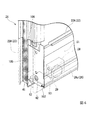
図1は、本発明の一実施形態に係る引き違い窓を屋内側から見た斜視図である。図2は、本発明の一実施形態に係る引き違い窓の鉛直断面図である。図3は、図2をA−Aで切断した水平断面図である。なお、図1において、枠体の図示を省略している。
図1から図3に示すように、引き違い窓100は、開口部Wに設けられ、四角形枠状に形成された枠体1と、枠体1内に嵌め込まれた外障子2X及び内障子2Yと、を備えている。
なお、以下の説明において、屋外側と屋内側とを結ぶ方向を見込み方向と称し、障子の上下方向及び上下方向と交差して外障子2X(内障子2Y)に沿う左右方向を見付け方向と称する。
Hereinafter, a sliding window will be described with reference to FIGS. 1 to 4 as an example of a fitting provided in an opening of a building according to an embodiment of the present invention.
FIG. 1 is a perspective view of a sliding window according to an embodiment of the present invention as viewed from the indoor side. FIG. 2 is a vertical sectional view of a sliding window according to an embodiment of the present invention. FIG. 3 is a horizontal sectional view of FIG. 2 cut along AA. In addition, in FIG. 1, illustration of a frame is abbreviate | omitted.
As shown in FIG. 1 to FIG. 3, the sliding
In the following description, a direction connecting the outdoor side and the indoor side is referred to as a prospective direction, and a horizontal direction along the vertical direction and the vertical direction of the shoji that crosses the
枠体1は、水平方向に延在する上枠11及び下枠12と、上枠11の両端部と下枠12の両端部とをそれぞれ連結し上下方向に延在する縦枠13と、を有している。
The
図2に示すように、上枠11は、屋外側に設けられ金属製の金属上枠11Aと、屋内側に設けられ樹脂製の樹脂上枠11Bと、を有している。金属上枠11Aと樹脂上枠11Bとは連結されている。
As shown in FIG. 2, the
下枠12は、屋外側に設けられ金属製の金属下枠12Aと、屋内側に設けられ樹脂製の樹脂下枠12Bと、を有している。金属下枠12Aと樹脂下枠12Bとは連結されている。
The
金属下枠12Aには、外障子2Xを支持する外側レール16が設けられている。樹脂下枠12Bには、内障子2Yを支持する内側レール17が設けられている。
The metal
図3に示すように、縦枠13は、屋外側に設けられ金属製の金属縦枠13Aと、屋内側に設けられ樹脂製の樹脂縦枠13Bと、を有している。金属縦枠13Aと樹脂縦枠13Bとは連結されている。
As shown in FIG. 3, the
図1に示すように、外障子2X及び内障子2Yは、それぞれ四方枠状に形成された框体20と、框体20内に納められた複層ガラス30と、を有している。
As shown in FIG. 1, the external obstacle 2 </ b> X and the internal obstacle 2 </ b> Y each have a
框体20は、水平方向に延在する上框21及び下框22と、上框21の両端部と下框22の両端部とをそれぞれ連結し上下方向に延在する縦框23と、を有している。
The
図2に示すように、上框21は、屋外側に設けられ金属製の金属上框21Aと、屋内側に設けられ樹脂製の樹脂上框21Bと、を有している。金属上框21Aと樹脂上框21Bとは連結されている。
As shown in FIG. 2, the
下框22は、屋外側に設けられ金属製の金属下框22Aと、屋内側に設けられ樹脂製の樹脂下框22Bと、を有している。金属下框22Aと樹脂下框22Bとは連結されている。
The
金属下框22Aの下部に配置される底板部26には、上下方向に貫通する戸車収容孔(加工孔)27が左右両端部近傍に形成されている。下枠12に沿って左右方向に走行可能な戸車28は戸車収容孔27に挿通され、底板部26の上部に形成された中空部S1内に配置されている。
The
図3に示すように、縦框23は、屋外側に設けられ金属製の金属縦框23Aと、屋内側に設けられ樹脂製の樹脂縦框23Bと、を有している。金属縦框23Aと樹脂縦框23Bとは連結されている。
As shown in FIG. 3, the
金属上框21A、金属下框22A及び金属縦框23Aには、それぞれ断面略コの字状のガラス保持溝31が形成されている。複層ガラス30の四辺の端部は、断面略U字状のグレージングチャンネル32で介して、ガラス保持溝31に収容されている。
A
次に、上記の引き違い窓100に設けられた加熱発泡材について説明する。
加熱発泡材は、火災時に、所定の温度に達したら膨張発泡するものである。
Next, the heating foam material provided in said sliding
The heated foam material expands and foams when a predetermined temperature is reached in a fire.
図4は、引き違い窓100の要部の斜視図であり、外障子2Xの金属下框22Aの金属縦框23A側の端部を示している。金属縦框23Aは二点鎖線で示している。
図2及び図4に示すように、外障子2X及び内障子2Yには、それぞれ金属下框22Aの底板部26の上面(複層ガラス30側の面)26uには、加熱発泡材(第二加熱発泡材)101が設けられている。加熱発泡材101は、戸車28よりも金属縦框23A側に配置されている。金属縦框23Aの金属下框22A側の端部には、金属下框22Aの中空部S1を閉塞する閉塞板41が設けられている。閉塞板41には、戸車28の高さ位置を調整するためにドライバー等の工具を挿通させる戸車調整孔42が設けられている。火災時には、加熱発泡材101は、見付け方向(上方)に発泡して、中空部S1の金属縦框23A側の端部を閉塞し、戸車調整孔42を塞ぐ。本実施形態では、加熱発泡材101は、2枚積層された配置されている。戸車収容孔27及び戸車調整孔42は、それぞれ金属下框22Aの見込み方向の略中央近傍に配置されている。
FIG. 4 is a perspective view of a main part of the sliding
As shown in FIGS. 2 and 4, the
外障子2Xにおいて、金属下框22Aの底板部26の屋内側の端部には、下方に向かって延びる延出壁部26cが設けられている。底板部26において、延出壁部26cよりも屋外側には延出壁部26dが設けられている。見込み方向に対向して配置された延出壁部26c,26dの先端部には、それぞれ対向する延出壁部26d,26c側に折曲された保持壁部(保持部、第二面)26e,26fが設けられている。
In the
金属下框22Aの底板部26の下面26bには、加熱発泡材102が設けられている。加熱発泡材102は、金属下框22Aの左右方向にわたって配置されている。加熱発泡材102は、底板部26の下面26bに沿って配置されるとともに、保持壁部26e,26fにより保持され、下方への落下が抑制されている。
A
組み立て時には、加熱発泡材102を、金属下框22Aの左右方向の一方の端部から、底板部26と保持壁部26e,26fとの間に挿入する。その後、保持壁部26e,26fのうち少なくとも一方を上方に曲げて(かしめて)、保持壁部26e,26fで加熱発泡材102を押さえつけて、加熱発泡材102を底板部26の下面26bに沿わせる。保持壁部を曲げる際には、保持壁部26e,26fのうち屋内側に配置された保持壁部26eを曲げる方が施工性がよい。
At the time of assembly, the
保持壁部26e,26fは、平滑な面として形成されている。金属下枠12Aにおいて、保持壁部26e,26fと対向する下壁部(第一面)18は、保持壁部26e,26fに沿って平滑な面として形成されている。火災時には、加熱発泡材102は、見付け方向(下方)に発泡して、金属下框22Aと金属下枠12Aとの間の隙間を塞ぐ。また、樹脂製の戸車28が溶けて外障子2Xが落下した際には、外障子2Xの保持壁部26e,26fが金属下枠12Aの下壁部18に当接する。保持壁部26e,26f及び下壁部18は互いに沿って平滑に形成されているため、当接する面積を大きく確保される。これにより、燃焼ガスの屋内側への回り込みが抑制される。また、火災時に、引き違い窓100において、上部の温度よりも下部の温度の方が低いため、下枠12側では、燃焼ガスが屋外側に向かって(図2に示す矢印P参照)排出される。
The holding wall portions 26e and 26f are formed as smooth surfaces. In the metal
なお、火災時には、樹脂製の戸車28が溶けた後に、種々の加熱発泡材が発泡して、枠体1と框体20との間の隙間を塞ぎ、当該隙間からガスを屋内側に浸入させない構成である。
In the event of a fire, after the
外障子2Xにおいて、金属下框22Aの屋外側に配置される屋内側壁部50には、不図示の取付孔が形成され、当該取付孔にサブロック24が固定されている。サブロック24は、外障子2X、内障子2Yが閉じた状態で、サブロック24の不図示のロック部材を内障子に係合して、外障子2X、内障子2Yのスライドを規制するものである。
In the
金属下框22Aの屋外側に配置される屋外側壁部51の屋内側の面には、加熱発泡材103が設けられている。火災時には、加熱発泡材103は、見込み方向(屋内側)に発泡して、金属下框22Aの中空部S2を塞ぐ。樹脂製のサブロック24は溶解してしまうため、加熱発泡材103がサブロック24の取付孔を塞ぐことは延焼抑制の上で効果的である。また、同様に、小開口ストッパーの取付孔(不図示)も加熱発泡材103が塞ぐことができる。
A
内障子2Yにおいて、金属下框22Aの底板部26の下面26bには、加熱発泡材104が設けられている。加熱発泡材104は、金属下框22Aの戸車28よりも金属縦框23A側の端部に配置されている。火災時には、加熱発泡材104は、見付け方向(下方)に発泡して、金属下框22Aと金属下枠12Aとの間の隙間を塞ぐ。
In the
図3に示すように、外障子2X及び内障子2Yにおいて、外障子2X及び内障子2Yが閉まった際に縦枠13側に配置される金属縦框23Aには、金属縦枠13Aに対向する第一側壁部61が設けられている。第一側壁部61には、戸車調整孔(加工孔)62(図4参照)が設けられている。第一側壁部61の戸車調整孔62、閉塞板41の戸車調整孔42及び戸車28の調整螺子29は、左右方向に沿って一直線上に配置されている。
As shown in FIG. 3, in the
第一側壁部61の屋外側の端部近傍には、縦枠13側と反対側に折曲された折曲壁部63が設けられている。折曲壁部63の端部には、屋外側に延びる第二側壁部64が設けられている。第二側壁部64の屋外側の端部には、縦枠13側に向かって延びる延出壁部65が設けられている。第一側壁部61の端部(保持部)61aは、折曲壁部63よりも屋外側に位置している。延出壁部65の屋内側の面には、屋内側に向かって突出する保持壁部(保持部)65aが設けられている。
A
第二側壁部64において、見込み方向に沿い、金属縦枠13Aに対向する面(見込み面)64aには、加熱発泡材(第一加熱発泡材)105が設けられている。加熱発泡材105は、金属縦框23Aの上下方向略全長にわたって配置されている。加熱発泡材105は、第二側壁部64の見込み面64aに沿って配置されるとともに、第一側壁部61の端部61a及び保持壁部65aにより保持され、金属縦枠13A側への移動が抑制されている。また、第一側壁部61の端部61a及び保持壁部65aの上下両端面は、金属縦框23Aの上下両端部にそれぞれ設けられたコーナーピース(不図示)に当接して、加熱発泡材105の上下端部は塞がれている。
In the second
本実施形態では、第一側壁部61に沿って、外障子2X、内障子2Yをそれぞれ屋内側に引き寄せる機能を有する引き寄せピース67が設けられている。引き寄せピース67は、見込み方向に稼働させて位置調整を行うため、屋外側の端部は延出壁部65まで延びている。このため、折曲壁部63を設けて、加熱発泡材105を引き寄せピース67よりも左右方向に内側に配置する構成としている。これにより、加熱発泡材105に加工(例えば引き寄せピース67を配置するための開口等)を設けずとも、加熱発泡材105を金属縦框23Aの全長にわたって配置することができる。
In the present embodiment, a pulling
組み立て時には、加熱発泡材105は、金属縦框23Aの上下方向の一方の端部から、第二側壁部64と第一側壁部61の端部61a及び保持壁部65aとの間に挿入される。その後、第一側壁部61の端部61a及び保持壁部65aのうち少なくとも一方を第二側壁部64側に曲げて(かしめて)、第一側壁部61の端部61a及び保持壁部65aで加熱発泡材105を押さえつけて、加熱発泡材105を第二側壁部64の見込み面64aに沿わせる。曲げる際には、第一側壁部61の端部61a及び保持壁部65aのうち、保持壁部65aは延出壁部65があるため作業がしずらいため、第一側壁部61の端部61aの方が好ましい。
At the time of assembly, the
図4に示すように、加熱発泡材105は、戸車調整孔62より見込み方向にずれた位置、本実施形態では屋外側に設けられている。また、図3に示すように、加熱発泡材105は、金属縦框23Aの見込み方向の中央よりも屋外側に偏心した位置に配置されている。加熱発泡材105は、第一側壁部61の端部61a及び延出壁部65の間に嵌め込まれている。火災時には、加熱発泡材105は、見付け方向に発泡して、金属縦框23Aと金属縦枠13Aとの間の隙間を塞ぐ。発泡後、加熱発泡材102と加熱発泡材105とは連続する。
As shown in FIG. 4, the
図3に示すように、金属縦框23Aのガラス保持溝31を形成し複層ガラス30と対向する壁部66には、複層ガラス30側の面に、加熱発泡材106が設けられている。図4に示すように、加熱発泡材106は、金属縦框23Aの上下方向に延び、下端部が閉塞板41の上方に位置している。火災時には、加熱発泡材106は、見付け方向に発泡して、金属縦框23Aと複層ガラス30との間の隙間を塞ぐ。
As shown in FIG. 3, a
図2に示すように、外障子2X及び内障子2Yにおいて、金属上框21Aのガラス保持溝31を形成し、複層ガラス30と対向する壁部71には、複層ガラス30側の面に、加熱発泡材107が設けられている。加熱発泡材107は、金属上框21Aの左右方向に延びている。火災時には、加熱発泡材107は、見付け方向(下方)に発泡して、金属上框21Aと複層ガラス30との間の隙間を塞ぐ。
As shown in FIG. 2, in the
金属上框21Aの上部に配置された上壁部72の上面(金属上枠11A側の面)には、加熱発泡材108が設けられている。加熱発泡材108は、金属上框21Aの左右方向に延びている。火災時には、加熱発泡材108は、見付け方向(上方)に発泡して、金属上框21Aと金属上枠11Aとの間の隙間を塞ぐ。
A
金属上枠11Aの下面(金属上框21A側の面)84には、複数の加熱発泡材が設けられている。加熱発泡材109は、外障子2Xの上方に設けられている。加熱発泡材109は、金属上枠11Aにおいて、外障子2Xが閉まった際に隣り合う縦枠13側寄りに配置されている。加熱発泡材110は、内障子2Yの上方に設けられている。加熱発泡材110は、金属上枠11Aにおいて、内障子2Yが閉まった際に隣り合う縦枠13側寄りに配置されている。
A plurality of heating foam materials are provided on the lower surface (surface on the metal
加熱発泡材109,110は、枠体1のコーナー部にピース状に配置され、接着剤で金属上枠11Aに固定されている。金属縦框23Aに設けられた加熱発泡材105及び金属上枠11Aに設けられた加熱発泡材109が発泡することで、コーナー部において枠体1と外障子2X、内障子2Yとの間の隙間は確実に塞がれる。外障子2Xにおいて、発泡後、加熱発泡材108と加熱発泡材109とは連続する。
The heating foams 109 and 110 are arranged in a piece shape at the corner of the
加熱発泡材111は、加熱発泡材110の下側に、不図示の風止め板と一体で設けられている。加熱発泡材111は、召合せ部分に配置されている。火災時には、加熱発泡材109,110,111は、見付け方向(下方)に発泡して、金属上枠11Aと金属上框21Aとの間の隙間を塞ぐ。内障子2Yにおいて、発泡後、加熱発泡材108と加熱発泡材110とは連続する。
The
金属下枠12Aと樹脂下枠12Bとの間には、不図示の風止め板と一体で、加熱発泡材112が設けられている。火災時には、加熱発泡材112は、見付け方向に発泡して、金属下枠12Aと樹脂下枠12Bとの間の隙間を塞ぐ。
Between the metal
図3に示すように、外障子2Xにおいて、金属縦框23Aの召合せ部分には、屋内側の面に加熱発泡材113が設けられている。内障子2Yにおいて、金属縦框23Aの召合せ部分には、屋外側の面に加熱発泡材114が設けられている。加熱発泡材113,114は、金属縦框23Aの略全長にわたって配置されている。火災時には、加熱発泡材113は屋内側に向かって発泡し、加熱発泡材114は屋外側に向かって発泡する。発泡した加熱発泡材113,114は、外障子2Xの金属縦框23Aの召合せ部分と内障子2Yの金属縦框23Aの召合せ部分との間の隙間を塞ぐ。発泡後、加熱発泡材113と加熱発泡材102とは連続するとともに、加熱発泡材113と加熱発泡材114とは連続する。
As shown in FIG. 3, in the
次に、その他の部分の詳細な構成について説明する。
図3に示すように、外障子2X及び内障子2Yにおいて、樹脂縦框23Bには、貫通孔68が形成され、貫通孔68には樹脂製の引手81が嵌合されている。金属縦框に引手を設ける場合には、金属縦框に形成された引手が配置される貫通孔から金属縦框の中空部に燃焼ガスが溜まり、燃焼ガスを屋内側にもれないように封止する必要があるが、本発明では、樹脂縦框23Bに加工を施しているため、封止するための加工等が不要である。
Next, the detailed configuration of other parts will be described.
As shown in FIG. 3, in the external obstacle 2 </ b> X and the internal obstacle 2 </ b> Y, the resin
また、図2に示すように、内障子2Yにおいて、金属下框22Aの底板部26と反対側に配置される上壁部52、上壁部52の屋内側と底板部26の屋内側とを連結する屋内側壁部53、及び底板部26に沿って、補強材82が設けられている。補強材82は、屋外側に向かって開口する見込み方向に沿った鉛直断面視でコ字状をなしている。補強材82は、金属下框22Aの左右の戸車28の間に配置されている。内障子2Yの金属下框22Aの厚み(見込み方向の厚み)は、外障子2Xの金属下框22Aの厚み(見込み方向の厚み)よりも薄いため、補強材82により金属下框22Aが補強され強度が確保されている。
In addition, as shown in FIG. 2, the inner wall of the
また、金属上框21A、金属下框22A及び金属縦框23Aに沿って、気密ラインが形成されているため、障子自体の防火性を高めることができる。
Moreover, since the airtight line is formed along the
図3に示すように、金属縦枠13Aにおいて、見込み方向に沿う側板部91には、左右方向の内側(外障子2X側、内障子2Y側)に向かって突出し、金属製のフィン(変位規制部)92,93が設けられている。フィン92は屋外側に設けられ、フィン93は屋内側に設けられている。なお、外障子2X、内障子2Yにおけるフィン92,93に対向し見込み方向に沿う部分は、金属材料で構成されている。
As shown in FIG. 3, in the metal
さらに、金属縦枠13Aにおいて、フィン92,93の見込み方向の間には、フィン94が設けられている。フィン94は、引き寄せピース67に当接している。
Further, in the metal
金属縦枠13Aにおいて、壁部66と第一側壁部61との間に、ホロー部95が形成されている。ホロー部95は、平面視略矩形状に形成されるとともに、折曲壁部63及び第二側壁部64により、矩形状の角部が内方に凹んだ形状をなしている。また、ホロー部95は、延出壁部65よりも屋内側に凹んだ形状をなしている。
In the metal
図1に示すように、金属下枠12Aにおいて、見込み方向に沿う底板部96の屋外側の端部には、上方に向かって突出する金属製のフィン97が設けられている。また、底板部96の上方に配置された上板部98の屋外側の端部には、下方に向かって突出する金属製のフィン99が設けられている。フィン97の方が99よりも屋外側に配置されている。外障子2Xにおけるフィン97,99に対向し見込み方向に沿う部分は、金属材料で構成されている。
As shown in FIG. 1, in the metal
このように構成された引き違い窓100では、加熱発泡材105は金属縦框23Aの見込み方向に沿う見込み面64aに設けられていて、火災時には、加熱発泡材105が見付け方向に発泡して、金属縦框23Aと金属縦枠13Aとの間の隙間を塞ぐ。詳細には、金属縦枠13Aの側板部91と、フィン94と、金属縦框23Aの第二側壁部64と、延出壁部65とで囲まれた隙間を塞ぐ。加熱発泡材が金属縦框の見付け方向に沿って配置されている場合には、加熱発泡材は金属縦框と金属縦枠との間の隙間を塞ぐのに十分は幅(見付け方向の幅)が必要となり、これにともない加熱発泡材を支持する金属縦框の見付け方向の幅を大きく確保する必要がある。本発明では、加熱発泡材105は見付け方向に発泡することで金属縦框23Aと金属縦枠13Aとの間の隙間を塞ぐ構成であるため、金属縦框23Aの見付け方向の幅を大きくする必要がなく、金属縦框23Aの見栄えを良好とすることができる。
In the sliding
また、加熱発泡材105は見付け方向に発泡して金属縦框23Aと金属縦枠13Aとの間の隙間を塞ぐため、外障子2X及び内障子2Yが縦枠13から離間するように見付け方向に反っても、金属縦框23Aと金属縦枠13Aとの間の隙間からの延焼を抑制することができる。
In addition, the
外障子2X及び内障子2Yが見込み方向に反った場合には、外障子2X及び内障子2Yの屋外側への変位がフィン92,97で規制されるとともに、外障子2X及び内障子2Yの屋内側への変位がフィン93,99で規制される。
When the
また、加熱発泡材105は金属縦框23Aの見込み面64aに戸車調整孔62より見込み方向にずれた位置に設けられているため、金属縦框23Aの上下方向にわたって配置することができる。よって、金属縦框23Aと金属縦枠13Aとの間の隙間を、金属縦框23Aの全長にわたって塞ぐことができる。
Moreover, since the
また、金属下框22Aの底板部26の上面26uには戸車28よりも金属縦框23A側に加熱発泡材101が設けられていて、火災時に、加熱発泡材101が見付け方向に発泡して、金属下框22Aの中空部S1を塞ぐ。よって、金属下框22Aから金属縦框23Aへ燃焼ガスの回り込みを抑制することができる。
In addition, a
また、加熱発泡材102は金属下框22Aの保持壁部26e,26fにより保持され、加熱発泡材104は金属縦框23Aの第一側壁部61の端部61a及び保持壁部65aにより保持されている。よって、加熱発泡材102,104がそれぞれ金属下框22A及び金属縦框23Aから外れたり、落下したりすることが抑制される。
Further, the
また、金属縦框23Aに引き寄せピース67が設けられている場合でも、金属縦框23Aにおいて引き寄せピース67が設けられる位置よりも左右方向の内側に加熱発泡材105を設けることで、金属縦框23Aと金属縦枠13Aとの隙間を塞ぎ、延焼を抑制することができる。
Moreover, even when the
また、火災時に、樹脂製の戸車28が溶けて外障子2Xが落下した際には、外障子2Xの金属下框22Aの保持壁部26e,26fが金属下枠12Aの下壁部18に当接する。保持壁部26e,26f及び下壁部18は互いに沿って平滑に形成されているため、当接する面積を大きく確保される。これにより、燃焼ガスの屋内側へ回り込みを抑制することができる。
Further, in the event of a fire, when the
なお、上述した実施の形態において示した各構成部材の諸形状や組み合わせ等は一例であって、本発明の主旨から逸脱しない範囲において設計要求等に基づき種々変更可能である。 The various shapes and combinations of the constituent members shown in the above-described embodiments are merely examples, and various modifications can be made based on design requirements and the like without departing from the gist of the present invention.
例えば、上記に示す実施形態では、障子の框体の見込み方向に沿う見込み面に形成される加工孔として、戸車収容孔27及び戸車調整孔62を例に挙げて説明したが、本発明はこれに限られず、框体20の内部に空気を導入する空気導入孔等であってもよい。
For example, in the embodiment described above, the
また、上記に示す実施形態では、引き違い窓100を例に挙げて説明したが、縦辷り出し窓や框ドア等の開き窓においても、障子の框体における枠体と対向し、見込み方向に沿う見込み面には、第一加熱発泡材が設けることで、同様の効果を奏することができる。
Further, in the embodiment described above, the sliding
1…枠体
2X…外障子
2Y…内障子
11…上枠
11A…金属上枠
11B…樹脂上枠
12…下枠
12A…金属下枠
12B…樹脂下枠
13…縦枠
13A…金属縦枠
13B…樹脂縦枠
16…外側レール
17…内側レール
18…下壁部(第一面)
20…框体
21…上框
21A…金属上框
21B…樹脂上框
22…下框
22A…金属下框
22B…樹脂下框
23…縦框
23A…金属縦框
23B…樹脂縦框
26…底板部
26e,26f…保持壁部(保持部)
27…戸車収容孔(加工孔)
28…戸車
31…ガラス保持溝
32…グレージングチャンネル
41…閉塞板
42…戸車調整孔
61a…端部(保持部)
62…戸車調整孔(加工孔)
64…第二側壁部
64a…見込み面
65a…保持壁部(保持部)
67…引き寄せピース
92,93…フィン(変位規制部)
100…引き違い窓
101…加熱発泡材(第二加熱発泡材)
102…加熱発泡材
105…加熱発泡材(第一加熱発泡材)
W…開口部
DESCRIPTION OF
20 ...
27. Door carriage accommodation hole (processing hole)
28 ...
62 ... Door adjustment hole (processing hole)
64 ...
67 ... attracting
100 ... Sliding
102 ...
W ... Opening
Claims (11)
該枠体の内部に、見付け方向にスライド可能に設けられた障子と、を備え、
前記障子の框体における前記枠体と対向し、見込み方向に沿う見込み面には、第一加熱発泡材が設けられていることを特徴とする建具。 A frame provided at the opening of the structure;
A shoji screen provided inside the frame so as to be slidable in the direction of finding,
A joinery characterized in that a first heating foam material is provided on a prospective surface that faces the frame body in the casing of the shoji and extends along the prospective direction.
前記第一加熱発泡材は、前記加工孔に対して前記見込み方向にずれた位置に設けられている請求項1または2に記載の建具。 In the prospective surface along the prospective direction of the casing of the shoji, a processing hole is formed,
The joinery according to claim 1 or 2, wherein the first heating foam material is provided at a position shifted in the prospective direction with respect to the processing hole.
前記加工孔は、前記框体に形成され前記戸車が配置される戸車収容孔及び前記框体に前記戸車を臨むように形成された戸車調整孔の少なくとも一方である請求項3に記載の建具。 The housing is provided with a door slidable in the direction of finding,
The fitting according to claim 3, wherein the processing hole is at least one of a door housing accommodation hole formed in the housing and where the door wheel is disposed, and a door wheel adjustment hole formed so as to face the door wheel.
前記枠体の下枠には、前記障子の下框と対向する側に、第一面が形成され、
前記下框には、前記下枠と対向する側に、前記第一面に対応した形状の第二面が形成されている請求項1から7のいずれか一項に記載の建具。 The housing is slidable in the direction of finding and is provided with a resin door.
In the lower frame of the frame body, a first surface is formed on the side facing the lower arm of the shoji,
The joinery according to any one of claims 1 to 7, wherein a second surface having a shape corresponding to the first surface is formed on the lower heel on a side facing the lower frame.
前記下框には、前記戸車収容孔よりも屋内側且つ前記下枠と対向する側に、前記第一加熱発泡材を設けた請求項6に記載の建具。 In the lower frame of the frame body, a first surface is formed on the side facing the lower arm of the shoji,
The joinery according to claim 6, wherein the first heating foam material is provided on the lower jar on the indoor side and the side facing the lower frame with respect to the door carriage housing hole.
前記下框の下部に配置された底板部における前記枠体の下枠と反対側の面には、前記戸車よりも前記障子の縦框側に、第二加熱発泡材が設けられている請求項6に記載の建具。 The lower arm of the shoji is formed in a hollow shape,
The second heating foam material is provided on the surface opposite to the lower frame of the frame body in the bottom plate portion arranged at the lower part of the lower rod, on the vertical rod side of the shoji screen than the door wheel. The joinery according to 6.
Priority Applications (1)
| Application Number | Priority Date | Filing Date | Title |
|---|---|---|---|
| JP2016213909A JP6831073B2 (en) | 2016-10-31 | 2016-10-31 | Joinery |
Applications Claiming Priority (1)
| Application Number | Priority Date | Filing Date | Title |
|---|---|---|---|
| JP2016213909A JP6831073B2 (en) | 2016-10-31 | 2016-10-31 | Joinery |
Publications (2)
| Publication Number | Publication Date |
|---|---|
| JP2018071237A true JP2018071237A (en) | 2018-05-10 |
| JP6831073B2 JP6831073B2 (en) | 2021-02-17 |
Family
ID=62114003
Family Applications (1)
| Application Number | Title | Priority Date | Filing Date |
|---|---|---|---|
| JP2016213909A Active JP6831073B2 (en) | 2016-10-31 | 2016-10-31 | Joinery |
Country Status (1)
| Country | Link |
|---|---|
| JP (1) | JP6831073B2 (en) |
Cited By (7)
| Publication number | Priority date | Publication date | Assignee | Title |
|---|---|---|---|---|
| JP2018104918A (en) * | 2016-12-22 | 2018-07-05 | 三協立山株式会社 | Fitting |
| JP2020007802A (en) * | 2018-07-10 | 2020-01-16 | 三協立山株式会社 | Joinery |
| JP2020090869A (en) * | 2018-12-07 | 2020-06-11 | Ykk Ap株式会社 | Joinery |
| JP2021017739A (en) * | 2019-07-19 | 2021-02-15 | Ykk Ap株式会社 | Fixture |
| JP2021080715A (en) * | 2019-11-18 | 2021-05-27 | 株式会社Lixil | Sash |
| JP2021156090A (en) * | 2020-03-30 | 2021-10-07 | Ykk Ap株式会社 | Fitting |
| JP2023118422A (en) * | 2022-02-15 | 2023-08-25 | Ykk Ap株式会社 | Fittings |
Citations (23)
| Publication number | Priority date | Publication date | Assignee | Title |
|---|---|---|---|---|
| JPS5366844U (en) * | 1976-11-09 | 1978-06-05 | ||
| US4660338A (en) * | 1984-05-17 | 1987-04-28 | Hugo Wagner | Sealing element for components of buildings |
| JP2004169472A (en) * | 2002-11-21 | 2004-06-17 | Tostem Corp | Opening device |
| JP2006225885A (en) * | 2005-02-15 | 2006-08-31 | Sankyo Tateyama Aluminium Inc | Vertical tight material |
| JP2008240475A (en) * | 2007-03-29 | 2008-10-09 | Howa Mach Ltd | Soundproof sash |
| JP2012225149A (en) * | 2011-04-08 | 2012-11-15 | Sankyotateyama Inc | Sash |
| JP2013113061A (en) * | 2011-11-30 | 2013-06-10 | Lixil Corp | Sash |
| JP2013127167A (en) * | 2011-12-19 | 2013-06-27 | Sankyotateyama Inc | Fixture |
| JP2014009494A (en) * | 2012-06-29 | 2014-01-20 | Sankyotateyama Inc | Fitting |
| JP2014070433A (en) * | 2012-09-28 | 2014-04-21 | Lixil Corp | Sash |
| JP2014070398A (en) * | 2012-09-28 | 2014-04-21 | Lixil Corp | Rolling shutter, and sash with rolling shutter |
| JP2014109092A (en) * | 2012-11-30 | 2014-06-12 | Lixil Corp | Opening part device |
| JP2014134022A (en) * | 2013-01-10 | 2014-07-24 | Lixil Corp | Opening device |
| JP2014196622A (en) * | 2013-03-29 | 2014-10-16 | 株式会社Lixil | Opening device |
| JP2014198959A (en) * | 2013-03-29 | 2014-10-23 | 株式会社Lixil | Opening device |
| JP2016000902A (en) * | 2014-06-11 | 2016-01-07 | Ykk Ap株式会社 | Fitting |
| JP2016023484A (en) * | 2014-07-22 | 2016-02-08 | Ykk Ap株式会社 | Fitting |
| JP2016023529A (en) * | 2014-07-24 | 2016-02-08 | Ykk Ap株式会社 | Resin fireproof fitting |
| JP2016037832A (en) * | 2014-08-11 | 2016-03-22 | 株式会社Lixil | Double sliding sash |
| JP2016044501A (en) * | 2014-08-26 | 2016-04-04 | Ykk Ap株式会社 | Sash and fitting |
| JP2016056555A (en) * | 2014-09-08 | 2016-04-21 | Ykk Ap株式会社 | Joinery |
| JP2016102352A (en) * | 2014-11-28 | 2016-06-02 | Ykk Ap株式会社 | Joinery |
| JP2016142007A (en) * | 2015-01-30 | 2016-08-08 | 積水化学工業株式会社 | Fireproof materials and building opening structure |
-
2016
- 2016-10-31 JP JP2016213909A patent/JP6831073B2/en active Active
Patent Citations (23)
| Publication number | Priority date | Publication date | Assignee | Title |
|---|---|---|---|---|
| JPS5366844U (en) * | 1976-11-09 | 1978-06-05 | ||
| US4660338A (en) * | 1984-05-17 | 1987-04-28 | Hugo Wagner | Sealing element for components of buildings |
| JP2004169472A (en) * | 2002-11-21 | 2004-06-17 | Tostem Corp | Opening device |
| JP2006225885A (en) * | 2005-02-15 | 2006-08-31 | Sankyo Tateyama Aluminium Inc | Vertical tight material |
| JP2008240475A (en) * | 2007-03-29 | 2008-10-09 | Howa Mach Ltd | Soundproof sash |
| JP2012225149A (en) * | 2011-04-08 | 2012-11-15 | Sankyotateyama Inc | Sash |
| JP2013113061A (en) * | 2011-11-30 | 2013-06-10 | Lixil Corp | Sash |
| JP2013127167A (en) * | 2011-12-19 | 2013-06-27 | Sankyotateyama Inc | Fixture |
| JP2014009494A (en) * | 2012-06-29 | 2014-01-20 | Sankyotateyama Inc | Fitting |
| JP2014070433A (en) * | 2012-09-28 | 2014-04-21 | Lixil Corp | Sash |
| JP2014070398A (en) * | 2012-09-28 | 2014-04-21 | Lixil Corp | Rolling shutter, and sash with rolling shutter |
| JP2014109092A (en) * | 2012-11-30 | 2014-06-12 | Lixil Corp | Opening part device |
| JP2014134022A (en) * | 2013-01-10 | 2014-07-24 | Lixil Corp | Opening device |
| JP2014196622A (en) * | 2013-03-29 | 2014-10-16 | 株式会社Lixil | Opening device |
| JP2014198959A (en) * | 2013-03-29 | 2014-10-23 | 株式会社Lixil | Opening device |
| JP2016000902A (en) * | 2014-06-11 | 2016-01-07 | Ykk Ap株式会社 | Fitting |
| JP2016023484A (en) * | 2014-07-22 | 2016-02-08 | Ykk Ap株式会社 | Fitting |
| JP2016023529A (en) * | 2014-07-24 | 2016-02-08 | Ykk Ap株式会社 | Resin fireproof fitting |
| JP2016037832A (en) * | 2014-08-11 | 2016-03-22 | 株式会社Lixil | Double sliding sash |
| JP2016044501A (en) * | 2014-08-26 | 2016-04-04 | Ykk Ap株式会社 | Sash and fitting |
| JP2016056555A (en) * | 2014-09-08 | 2016-04-21 | Ykk Ap株式会社 | Joinery |
| JP2016102352A (en) * | 2014-11-28 | 2016-06-02 | Ykk Ap株式会社 | Joinery |
| JP2016142007A (en) * | 2015-01-30 | 2016-08-08 | 積水化学工業株式会社 | Fireproof materials and building opening structure |
Cited By (12)
| Publication number | Priority date | Publication date | Assignee | Title |
|---|---|---|---|---|
| JP2018104918A (en) * | 2016-12-22 | 2018-07-05 | 三協立山株式会社 | Fitting |
| JP2020007802A (en) * | 2018-07-10 | 2020-01-16 | 三協立山株式会社 | Joinery |
| JP7152888B2 (en) | 2018-07-10 | 2022-10-13 | 三協立山株式会社 | Fittings |
| JP2020090869A (en) * | 2018-12-07 | 2020-06-11 | Ykk Ap株式会社 | Joinery |
| JP7061057B2 (en) | 2018-12-07 | 2022-04-27 | Ykk Ap株式会社 | Joinery |
| JP2021017739A (en) * | 2019-07-19 | 2021-02-15 | Ykk Ap株式会社 | Fixture |
| JP2021080715A (en) * | 2019-11-18 | 2021-05-27 | 株式会社Lixil | Sash |
| JP7324691B2 (en) | 2019-11-18 | 2023-08-10 | 株式会社Lixil | shoji |
| JP2021156090A (en) * | 2020-03-30 | 2021-10-07 | Ykk Ap株式会社 | Fitting |
| JP7364518B2 (en) | 2020-03-30 | 2023-10-18 | Ykk Ap株式会社 | fittings |
| JP2023118422A (en) * | 2022-02-15 | 2023-08-25 | Ykk Ap株式会社 | Fittings |
| JP7828778B2 (en) | 2022-02-15 | 2026-03-12 | Ykk Ap株式会社 | Building materials |
Also Published As
| Publication number | Publication date |
|---|---|
| JP6831073B2 (en) | 2021-02-17 |
Similar Documents
| Publication | Publication Date | Title |
|---|---|---|
| JP2018071237A (en) | Fixture | |
| JP5749129B2 (en) | Opening building materials | |
| JP6091924B2 (en) | Opening device | |
| JP5689046B2 (en) | Opening building materials | |
| JP2016044501A (en) | Sash and fitting | |
| KR101470536B1 (en) | Frame for windows and doors with excellent adiabatic effect | |
| JP2017031604A (en) | Fixture | |
| JP2014167199A (en) | Fireproof structure of lower frame of window shutter | |
| JP2015063800A (en) | Band window | |
| JP6158545B2 (en) | Fireproof structure of window shutter vertical frame | |
| JP6023229B2 (en) | Opening building materials | |
| JP2015218505A (en) | Foundation water drip member fitting structure and foundation water drip member | |
| JP6912344B2 (en) | Joinery | |
| KR20160071290A (en) | Roller thermal insulation structure of sliding window | |
| KR101571541B1 (en) | Installation structure of windows frame | |
| JP2014227780A (en) | Double-hung window | |
| JP6271133B2 (en) | Window shutter device | |
| JP5937849B2 (en) | Window shutter fire prevention structure | |
| JP6148050B2 (en) | Building wall structure | |
| JP2018123558A (en) | Joinery | |
| JP5303499B2 (en) | Refurbished sash unit and installation method of refurbished unit | |
| KR101976731B1 (en) | A bracket for mounting window frame | |
| JP6276674B2 (en) | Shutter fire prevention structure | |
| JP6861012B2 (en) | Joinery | |
| JP7595452B2 (en) | Setting blocks and fittings |
Legal Events
| Date | Code | Title | Description |
|---|---|---|---|
| A621 | Written request for application examination |
Free format text: JAPANESE INTERMEDIATE CODE: A621 Effective date: 20190827 |
|
| A977 | Report on retrieval |
Free format text: JAPANESE INTERMEDIATE CODE: A971007 Effective date: 20200630 |
|
| A131 | Notification of reasons for refusal |
Free format text: JAPANESE INTERMEDIATE CODE: A131 Effective date: 20200728 |
|
| A521 | Request for written amendment filed |
Free format text: JAPANESE INTERMEDIATE CODE: A523 Effective date: 20200928 |
|
| TRDD | Decision of grant or rejection written | ||
| A01 | Written decision to grant a patent or to grant a registration (utility model) |
Free format text: JAPANESE INTERMEDIATE CODE: A01 Effective date: 20201208 |
|
| A711 | Notification of change in applicant |
Free format text: JAPANESE INTERMEDIATE CODE: A712 Effective date: 20201218 |
|
| A61 | First payment of annual fees (during grant procedure) |
Free format text: JAPANESE INTERMEDIATE CODE: A61 Effective date: 20210105 |
|
| R150 | Certificate of patent or registration of utility model |
Ref document number: 6831073 Country of ref document: JP Free format text: JAPANESE INTERMEDIATE CODE: R150 |