JP2018009820A - Structure strain sensor and structure strain detection method - Google Patents
Structure strain sensor and structure strain detection method Download PDFInfo
- Publication number
- JP2018009820A JP2018009820A JP2016137169A JP2016137169A JP2018009820A JP 2018009820 A JP2018009820 A JP 2018009820A JP 2016137169 A JP2016137169 A JP 2016137169A JP 2016137169 A JP2016137169 A JP 2016137169A JP 2018009820 A JP2018009820 A JP 2018009820A
- Authority
- JP
- Japan
- Prior art keywords
- strain
- wiring
- stretchable
- strain sensor
- substrate
- Prior art date
- Legal status (The legal status is an assumption and is not a legal conclusion. Google has not performed a legal analysis and makes no representation as to the accuracy of the status listed.)
- Granted
Links
Images


Landscapes
- Measurement Of Force In General (AREA)
Abstract
【課題】本発明は、構造物にひび割れが生じても、構造物の変形を検出することが可能な構造物の歪センサを提供する。【解決手段】歪センサ10は、構造物の表面1aの歪を検出する歪センサ10であって、基板面30aに沿う方向に伸縮性を有する伸縮基板30と、導電性を有し、基板面30aに沿う方向に延びるように配線され、基板面30aに沿う方向に伸縮性を有する伸縮配線40と、を備える。【選択図】図2PROBLEM TO BE SOLVED: To provide a strain sensor of a structure capable of detecting deformation of the structure even if the structure is cracked. SOLUTION: A strain sensor 10 is a strain sensor 10 that detects strain on a surface 1a of a structure, and has a stretchable substrate 30 having elasticity in a direction along a substrate surface 30a and a substrate surface having conductivity. A telescopic wiring 40 that is wired so as to extend in a direction along the substrate surface 30a and has elasticity in a direction along the substrate surface 30a. [Selection diagram] Fig. 2
Description
本発明は、構造物の歪センサ及び構造物歪検出方法に関する。 The present invention relates to a structure strain sensor and a structure strain detection method.
従来、トンネル、橋梁、鉄塔、機械設備といった構造物の変形を確認する方法として、歪ゲージをセンサとして用いる方法が一般に知られている。例えば、コンクリート構造物の変形を確認する方法として、以下の特許文献1に記載された歪ゲージをセンサとして用いる方法が知られている。 Conventionally, as a method for confirming deformation of a structure such as a tunnel, a bridge, a steel tower, or a mechanical facility, a method using a strain gauge as a sensor is generally known. For example, as a method for confirming deformation of a concrete structure, a method using a strain gauge described in Patent Document 1 below as a sensor is known.
しかし、歪ゲージを設置した箇所にひび割れが生じると弾性歪が生じていた場合と比較してひび割れ幅に対応する大きな変形が生じる。このため、特許文献1に記載された歪ゲージを用いたセンサは、ひび割れに対する変形に追従できず、検出することができなくなってしまう問題がある。 However, when a crack is generated at a location where the strain gauge is installed, a large deformation corresponding to the crack width is generated as compared with a case where an elastic strain is generated. For this reason, the sensor using the strain gauge described in Patent Document 1 cannot follow the deformation with respect to the crack and cannot detect it.
本発明は、構造物にひび割れが生じても、構造物の変形を検出することが可能な構造物の歪センサを提供することを目的とする。 An object of the present invention is to provide a strain sensor for a structure that can detect deformation of the structure even if the structure is cracked.
第1の態様の歪センサは、構造物の表面の歪を検出する歪センサであって、基板面に沿う方向に伸縮性を有する伸縮基板と、導電性を有し、前記基板面に沿う方向に延びるように配線され、前記基板面に沿う方向に伸縮性を有する伸縮配線と、を備える。 The strain sensor according to the first aspect is a strain sensor that detects strain on the surface of a structure, and has a stretchable substrate having stretchability in a direction along the substrate surface, and a conductivity, and a direction along the substrate surface. And a stretchable wiring having a stretchability in a direction along the substrate surface.
本態様では、構造物に大きな歪が発生しても、伸縮基板及び伸縮配線が歪に対して伸縮するため、構造物にひび割れが生じても、構造物の変形を検出することが可能である。 In this aspect, even if a large strain occurs in the structure, the stretchable substrate and the stretchable wiring expand and contract with respect to the strain. Therefore, even if the structure is cracked, it is possible to detect the deformation of the structure. .
第2の態様の歪センサは、前記伸縮基板に前記伸縮配線が複数配列された第1の態様の歪センサである。 The strain sensor according to the second aspect is the strain sensor according to the first aspect in which a plurality of the stretchable wirings are arranged on the stretchable substrate.
本態様では、複数箇所の歪を別々に検出することができるため、構造物の表面における歪の分布を検出することができる。 In this aspect, since strain at a plurality of locations can be detected separately, the strain distribution on the surface of the structure can be detected.
第3の態様の歪センサは、伸縮配線が前記基板面に配置された印刷配線である第1又は第2の態様の歪センサである。 The strain sensor according to the third aspect is the strain sensor according to the first or second aspect, in which the expansion / contraction wiring is a printed wiring disposed on the substrate surface.
本態様では、加工された伸縮基板に対して伸縮配線を任意のパターンで設けることができるため、伸縮配線を簡単且つ安価に設けることができる。 In this aspect, since the stretchable wiring can be provided in any pattern on the processed stretchable substrate, the stretchable wiring can be provided easily and inexpensively.
第4の態様の歪センサは、前記伸縮基板及び前記伸縮配線が可撓性を有する第1から第3の態様のいずれかの歪センサである。 The strain sensor according to a fourth aspect is the strain sensor according to any one of the first to third aspects, wherein the stretchable substrate and the stretchable wiring have flexibility.
本態様では、歪センサを構造物の曲表面や凹凸表面に貼り付けることができる。 In this aspect, the strain sensor can be attached to the curved surface or the uneven surface of the structure.
第5の態様の歪センサは、前記伸縮配線の電気抵抗を検出する歪検出部をさらに備える第1から第4の態様のいずれかの歪センサである。 The strain sensor according to the fifth aspect is the strain sensor according to any one of the first to fourth aspects, further including a strain detection unit that detects an electrical resistance of the stretchable wiring.
本態様では、検出された電気抵抗から構造物の表面における歪を算出することができる。 In this aspect, the strain on the surface of the structure can be calculated from the detected electrical resistance.
第6の態様の歪センサは、前記歪検出部で検出した電気抵抗に基づく情報の無線送信を行う無線送信部をさらに備える第5の態様の歪センサである。 The strain sensor according to the sixth aspect is the strain sensor according to the fifth aspect, further comprising a wireless transmission unit that wirelessly transmits information based on the electrical resistance detected by the strain detection unit.
本態様では、遠隔における歪のモニタリングが可能となり、監視作業やメンテナンス作業の効率化を行うことができる。 In this aspect, it is possible to remotely monitor distortion, and it is possible to improve the efficiency of monitoring work and maintenance work.
第7の態様の歪センサは、少なくとも前記無線送信部に、電力を供給するバッテリをさらに備える第6の態様の歪センサである。 The strain sensor according to the seventh aspect is the strain sensor according to the sixth aspect, further comprising a battery that supplies power to at least the wireless transmission unit.
本態様では、無線送信部への電力の供給配線を設ける必要がないため、構造物に対して、歪センサを任意の場所に設置することができる。 In this aspect, since it is not necessary to provide power supply wiring to the wireless transmission unit, the strain sensor can be installed at an arbitrary position with respect to the structure.
第8の態様の構造物歪検出方法は、第1から第7のいずれかの態様の歪センサを構造物に設置する設置工程と、
前記伸縮配線の歪を検出する歪検出工程と、を実施する。
The structure distortion detection method according to the eighth aspect includes an installation step of installing the strain sensor according to any one of the first to seventh aspects on the structure;
A strain detecting step of detecting strain of the stretchable wiring.
本態様では、構造物に大きな歪が発生しても、伸縮基板及び伸縮配線が歪に対して伸縮するため、構造物にひび割れが生じても、構造物の変形を検出することが可能である。 In this aspect, even if a large strain occurs in the structure, the stretchable substrate and the stretchable wiring expand and contract with respect to the strain. Therefore, even if the structure is cracked, it is possible to detect the deformation of the structure. .
第9の態様の構造物歪検出方法は、前記検出した歪に基づく情報の無線送信を行う無線送信工程をさらに実施する第8の態様の構造物歪検出方法である。 The structural strain detection method according to the ninth aspect is the structural strain detection method according to the eighth aspect, further performing a wireless transmission step of performing wireless transmission of information based on the detected strain.
本態様では、遠隔における歪のモニタリングが可能となり、監視作業やメンテナンス作業の効率化を行うことができる。 In this aspect, it is possible to remotely monitor distortion, and it is possible to improve the efficiency of monitoring work and maintenance work.
本発明の構造物の歪センサは、構造物にひび割れが生じても、構造物の変形を検出することできる。 The structure strain sensor of the present invention can detect deformation of the structure even if the structure is cracked.
以下、本発明に係る各種実施形態について、図面を用いて説明する。 Hereinafter, various embodiments according to the present invention will be described with reference to the drawings.
「第一実施形態」
以下、本発明に係る歪センサの第一実施形態について、図1〜図6を参照して説明する。
"First embodiment"
Hereinafter, a first embodiment of a strain sensor according to the present invention will be described with reference to FIGS.
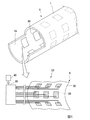
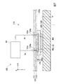
図1に示すように、歪測定システム5は、歪センサ10と、処理部90とを備える。
歪センサ10は、センサ本体部20と、伸縮基板30と、歪検出部60とを備え、コンクリート構造物1の表面1aに設置される。
センサ本体部20は複数有しており、伸縮基板30の一方の面に並べて配列されるとともに固定されている。
本実施形態では、複数のセンサ本体部20が配置された伸縮基板30が、トンネルに設置され、トンネルの内壁表面の歪を検出する。
As shown in FIG. 1, the strain measurement system 5 includes a
The
A plurality of sensor
In the present embodiment, a
図1に示すように、伸縮基板30は、複数のセンサ本体部20が配列された一方の面をコンクリート構造物1の表面1aに対向するように貼り付けられる。よって、複数のセンサ本体部20は、コンクリート構造物1の表面1aに面状に配置されている。
なお、図1の下部に示した図は、複数のセンサ本体部20を含む1枚の伸縮基板30の一部分を拡大した図であって、コンクリート構造物1に向かって、伸縮基板30を透視して複数のセンサ本体部20を見た図を示している。
歪センサ10は、後で詳しく示す歪検出部60において、コンクリート構造物1の表面1aにおけるセンサ本体部20が設置された各点についての歪を検出する。
As shown in FIG. 1, the
1 is an enlarged view of a part of one
The
本実施形態では、各センサ本体部20が固定された伸縮基板30を複数枚設け、コンクリート構造物1の表面1aの全体にわたって当該伸縮基板30を並べて貼り付けている。よって、複数のセンサ本体部20は、コンクリート構造物1の表面1aの全体にわたって並べて配置されている。
In the present embodiment, a plurality of
歪検出部60と処理部90とは、通信可能なように電線や光ファイバー等で接続されており、検出された各点の歪に基づく情報は、歪センサ10の歪検出部60から処理部90に出力される。
歪検出部60から送られてきた各点の歪に基づく情報は、処理部90において表示、印刷等によって出力され、作業者に提示される。処理部90は、各点の歪をそのまま出力するものであってもよいが、次に示すようにマップデータで出力するものであってもよい。
The
Information based on the distortion of each point sent from the
処理部90には、複数のセンサ本体部20が設置された各点と各点の位置との関係が予め記憶されている。処理部90は、当該記憶された当該関係から、検出された各点の歪に基づく情報とコンクリート構造物1の表面1aの位置とを関連付ける。
したがって、処理部90は、検出された各点の歪に基づく情報とコンクリート構造物1の表面1aの位置とを関連付けることによって、コンクリート構造物1の表面1aの歪のマップデータを作成することができる。
また、処理部90は、時間と検出された各点の歪に基づく情報との関係から、歪の時間変化を示すグラフを作成することができる。
作成されたマップデータやグラフは、処理部90において表示、印刷等によって出力され、作業者に提示される。作業者に提示されるマップデータは、歪と位置との関係を等高線やカラーマップで示すものであり、作業者に提示されるグラフは、時間と歪との関係を線グラフで示すものである。
歪と位置との関係を等高線やカラーマップで示すことで、作業者は、コンクリート構造物1の表面1aに沿った歪の二次元分布を評価することができる。
また、時間と歪との関係を線グラフで示すことで、作業者は、コンクリート構造物1のひび割れの発生やひび割れの進展を評価することができる。
本実施形態では、作業者は、当該マップデータや当該グラフからコンクリート構造物1の表面1a又はコンクリート構造物1の内部のひび割れを判断し、ひび割れの発生やひび割れの進展の報告又はひび割れ箇所の補修や保守を行う。
本実施形態に用いる処理部90は、CPU、記憶部、I/O部等を有するコンピュータシステムであればどのようなものを用いてもよいが、電気回路や電子回路で構成してもよい。また、任意の場所で検出された歪に基づく情報を確認できるように、処理部90としてノートパソコン、PDA、タブレット等の携帯端末を用いてもよい。
The
Therefore, the
In addition, the
The created map data and graph are output by display, printing, etc. in the
By showing the relationship between the strain and the position with contour lines or a color map, the operator can evaluate the two-dimensional distribution of the strain along the
Moreover, the operator can evaluate the generation | occurrence | production of the crack of the concrete structure 1, and progress of a crack by showing the relationship between time and distortion with a line graph.
In this embodiment, an operator judges the
As the
本実施形態の伸縮基板30の構造について説明する。
伸縮基板30は、可撓性を有する薄いシート状であるとともに、基板面30aに沿う方向に伸縮性を有する。本実施形態では、伸縮基板30として、ポリフッ化ビニリデン(PVDF)を用いている。
伸縮基板30を構成する伸縮性を有する材料としては、ポリフッ化ビニリデンの他に、ポリウレタン、シリコーンゴム、ポリ塩化ビニル、ポリエチレンテレフタレート、ポリエチレンナフタレート、パリレン、スチレンブタジエンゴム、クロロプレンゴム、アクリルゴムが挙げられる。また、当該材料に比べて低伸縮ながら布やポリイミドを用いることも可能である。
例えばポリウレタンゴムは、伸び(破断伸度)は1000%まで至り、シリコーンゴムでも伸び(破断伸度)は200%まで至るように、非常によく伸びる材料である。
The structure of the
The
Examples of the stretchable material constituting the
For example, polyurethane rubber is a material that stretches very well such that the elongation (breaking elongation) reaches 1000%, and the elongation (breaking elongation) of silicone rubber reaches 200%.
本実施形態のセンサ本体部20の構造について説明する。
図2は、コンクリート構造物1のX−Z平面における各センサ本体部20の断面を示す。
各センサ本体部20は、可撓性を有する伸縮配線40を備える。
The structure of the
FIG. 2 shows a cross section of each
Each
伸縮配線40は、コンクリート構造物1の表面1aに対し、対向するように配置され、コンクリート構造物1の表面1aに固定されている。本実施形態では、伸縮配線40の全体をコンクリート構造物1の表面1aに接着剤50で固定している。
伸縮配線40は、基板面30aに配線されており、少なくとも基板面30aに沿う方向に伸縮性を有している。本実施形態では、伸縮配線40として、ポリフッ化ビニデン系樹脂をバインダーとして、銀フレーク粒子、及び銀球状粒子を混ぜ合わせた複合材料を用いている。
The
The
伸縮配線40を構成する伸縮性のある材料としては、ポリフッ化ビニリデン系樹脂、銀フレーク及び銀球状粒子を混ぜ合わせた複合材料の他に、例えば、ポリフッ化ビニリデン系樹脂及び銀フレークを混ぜ合わせた複合材料が挙げられる。また、ポリフッ化ビニリデン系樹脂、銀フレーク、銀球状粒子及びグラフェンを混ぜ合わせた複合材料も挙げられる。さらに、ポリフッ化ビニリデン系樹脂、銀フレーク及びグラフェンを混ぜ合わせた複合材料、又はポリウレタン及び銀フレークを混ぜ合わせた複合材料が挙げられる。
As a stretchable material constituting the
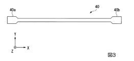
伸縮配線40は、導電性を有するパターンであって、固定されたコンクリート構造物1の表面1aの歪の変化に応じてパターンが変形することで電気抵抗が変化する。
本実施形態において、伸縮配線40は、図3に示すようなX方向に延び、両端に端部40a及び40bを有する直線状のパターンである。当該直線パターンとすることで、X方向の歪の変化を端部40aと40bとの間の電気抵抗の変化として検出することができる。
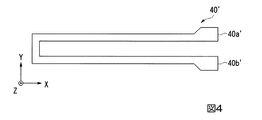
変形例として、伸縮配線を、X方向に延びつつ、X方向に一回折り返されたU字パターン(図4)であって、当該U字パターンの両端に端部40a′及び端部40b′を有する伸縮配線40′としてもよい。当該U字パターンとすることで、直線状のパターンに比べて歪に対する端部40a′と40b′と間の電気抵抗の変化を大きくすることができ、高感度な歪の検出が可能となる。
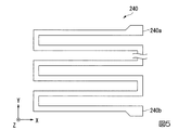
さらなる変形例として、伸縮配線を、X方向に複数回折り返したジグザグパターン(図5)であって、当該ジグザグパターンの両端に端部240a及び端部240bを有する伸縮配線240としてもよい。当該ジグザグパターンとすることで、歪に対する端部240aと端部240bとの間の電気抵抗の変化をさらに大きくすることができる。
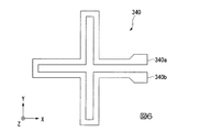
他の変形例として、伸縮配線を、Y方向の折り返しとX方向の折り返しとを組み合わせたクロスパタ−ン(図6)であって、当該クロスパターンの両端に端部340a及び端部340bを有する伸縮配線340としてもよい。当該クロスパターンとすることで、X方向及びY方向の歪の変化を、端部340aと端部340bとの間の電気抵抗の変化として検出することができる。
The
In the present embodiment, the
As a modified example, a telescopic wiring is a U-shaped pattern (FIG. 4) that extends in the X direction and is folded once in the X direction, and has
As a further modification, the expansion / contraction wiring may be a zigzag pattern (FIG. 5) that is bent back and forth in the X direction, and has an
As another modification, a cross pattern (FIG. 6) is a combination of an extension wire and a return in the Y direction and a return in the X direction, and has an
本実施形態では、伸縮配線40は、伸縮基板30の基板面30aにスクリーン印刷といった安価な方法によって成膜された印刷配線であるが、マスク印刷、インクジェット印刷、ディスペンサー印刷、グラビア印刷、フレキソ印刷、オフセット印刷等によって成膜された印刷パターンとしてもよい。さらに印刷に限らず、伸縮基板30の基板面30aに成膜できるなら、伸縮配線の信頼性向上のため、めっき、オーバーコートのような方法によって成膜してもよい。
伸縮配線40と伸縮基板30とが剥がれないようにするためには、以下の点に気を付ければよく、伸縮配線40と伸縮基板30との間の密着性を高くすることができる。
伸縮配線40と伸縮基板30との間に高い密着性を得るためには、化学的結合(水素結合)、物理的結合(ファンデルワールス力)、機械的結合(アンカー効果)が必要である。同系統の樹脂が伸縮配線40と伸縮基板30とに含まれる場合、両者の接着する際に加熱、加圧、溶解などの処理を行うことにより高い密着性が得られる。異種材料である場合、シランカップリング材やプライマー処理を施すことで高い密着性が得られる場合がある。
本実施形態では、伸縮配線40に含まれるポリマーと同種のポリフッ化ビニリデン樹脂を伸縮基板30へ使用した。よって、印刷時にはペースト中の溶剤が伸縮基板30を溶解し、印刷ののち加熱処理を施すと、伸縮配線40と伸縮基板30との密着性を高いものとすることが可能となる。
In this embodiment, the
In order to prevent the
In order to obtain high adhesion between the
In the present embodiment, the same type of polyvinylidene fluoride resin as the polymer contained in the
接着剤50は、伸縮基板30や伸縮配線40と同様に、可撓性を有するとともには、少なくとも基板面30aに沿う方向に伸縮性を有する。本実施形態では、シリコーン系材料からなる接着剤を用いているが、可撓性及び伸縮性を有する接着剤であれば、どのような接着剤であってもよい。
The adhesive 50 has flexibility as well as the
歪検出部60と各センサ本体部20とは、配線3a及び配線3bによって電気的に接続されている。
具体的には、配線3aと伸縮配線40の端部40aとが電気的に接続され、配線3bと伸縮配線40の端部40bとが電気的に接続されている。歪検出部60は、配線3aと配線3bとの間の電気抵抗を検出することによって、伸縮配線40の端部40aと40bとの間の電気抵抗を検出し、圧縮歪又は引張歪を測定する。
歪検出部60における電気抵抗の検出方式は、二端子測定法、四端子測定法、ホイートストンブリッジ等どのような方式を用いたものでもよい。
本実施形態において、歪検出部60は、トンネル内に設置されても、トンネル外に設置されてもどちらでも構わない。
The
Specifically, the
The detection method of the electrical resistance in the
In the present embodiment, the
本実施形態の歪センサ10の作用、効果について説明する。
本実施形態では、伸縮基板30及び伸縮配線40が基板面30aに沿う方向に伸縮性を有する。よって、コンクリート構造物1の表面1aに大きな歪が発生しても、伸縮基板30や伸縮配線40は伸縮するため、歪に対して耐性を有する。
本実施形態の歪センサ10の歪の最大レンジは、圧縮側についてはコンクリートの圧壊歪相当する10000μm程度、引張側については最大ひび割れ幅に相当する1〜2mm程度としている。
また、本実施形態の歪センサ10の歪の分解能は、少なくとも圧縮側については10μm程度、引張側についてはひび割れ幅に相当する0.1mm程度としている。
したがって、本実施形態の歪センサ10は、大きな歪が発生した後も歪を検出することができるため、長期にわたって歪を検出し続けることが可能となり、検出の度に検出現場に赴く必要がなく、常時遠隔での測定も可能となる。
The operation and effect of the
In the present embodiment, the
The maximum strain range of the
Further, the strain resolution of the
Therefore, since the
「第二実施形態」
以下、本発明に係る歪センサの第二実施形態について、図7を参照して説明する。
"Second embodiment"
Hereinafter, a second embodiment of the strain sensor according to the present invention will be described with reference to FIG.
本実施形態の歪センサは、第一実施形態と基本的に同じであるが、センサ本体部の構造が異なっている。 The strain sensor of this embodiment is basically the same as that of the first embodiment, but the structure of the sensor body is different.
本実施形態の歪測定システム105の歪センサ110は、複数のセンサ本体部120と、伸縮基板130と、歪検出部60とを備え、コンクリート構造物1の表面1aに設置される。複数のセンサ本体部120は、伸縮基板130の一方の面に並べて配列されるとともに固定されている。複数のセンサ本体部120のうちの一つを図7に示す。
The
本実施形態の伸縮基板130の構造について説明する。
伸縮基板130は、基板層131及び粘着層132を備え、合わせて50μmの厚さを有する。伸縮基板130は、可撓性を有するとともに、基板面130aに沿う方向に伸縮性を有する。本実施形態では、基板層131、粘着層132にそれぞれ、ポリイミド、シリコーン系材料を用いている。本実施形態において、粘着層132は、基板層131全体に設けているが、粘着層132は、基板層131全体のうち、複数のセンサ本体部120が固定される位置だけに設けるものであってもよい。又は粘着層132は無くてもよく、その場合は基板層131と41が同種又は密着性の高い材料で構成される。
The structure of the
The
伸縮基板130は、さらに、表裏面に貫通する2つの導通部134a、134bと、配線3aに接続されるコンタクト部133aと、配線3bに接続されるコンタクト部133bと、を備える。
The
導通部134a及びコンタクト部133aは、後に示す伸縮配線40の端部40aのZ方向位置にそれぞれ配置され、配線3aと伸縮配線40の端部40aとを電気的に接続する。
同様に、導通部134b及びコンタクト部133bは、伸縮配線40の端部40bにZ方向位置にそれぞれ配置され、配線3bと伸縮配線40の端部40bとを電気的に接続する。
よって、配線3aと配線3bとの間の電気抵抗を測定することで、伸縮配線40の端部40aと40bとの間の電気抵抗を検出することができる。
The
Similarly, the conductive portion 134b and the contact portion 133b are respectively disposed at the
Therefore, by measuring the electrical resistance between the
本実施形態のセンサ本体部120の構造について説明する。
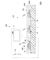
図7は、コンクリート構造物1のX−Z平面における一つのセンサ本体部120の断面を示す。
The structure of the sensor
FIG. 7 shows a cross section of one sensor
センサ本体部120は、端部40a及び端部40bを備える伸縮配線40と、コーティング層41と、X方向に互いに離れて配置された2つの脚部42a及び脚部42bと、を備える。伸縮配線40は、コーティング層41を合わせて50μmの厚さを有する。
The sensor
伸縮配線40は、コンクリート構造物1の表面1aに対し対向するように配置され、コンクリート構造物1の表面1aにコーティング層41及び接着剤50を介して固定されている。本実施形態では、伸縮配線40は、脚部42aと脚部42bとの間において、接着剤50で固定されている。
本実施形態の場合、伸縮配線40のうち、脚部42aの周辺及び脚部42bの周辺部分は、後で説明するとおり、コンクリート構造物1の表面1aに固定されないこととなり、歪を検出することができない。
しかし、伸縮配線40のうち、脚部42aの周辺及び脚部42bの周辺を除いた大部分は、コンクリート構造物1の表面1aへ固定されているため、コンクリート構造物1の表面1aの歪を当該大部分で検出することができる。
The
In the case of this embodiment, the periphery of the
However, most of the
コーティング層41は、伸縮配線40を覆うように伸縮基板130の基板面130aに配置されている。コーティング層41は、可撓性を有するとともには、基板面130aに沿う方向に伸縮性を有する。
本実施形態において、コーティング層41は、シリコーンで形成されている。
The coating layer 41 is disposed on the
In the present embodiment, the coating layer 41 is made of silicone.
脚部42a及び脚部42bは、コンクリート構造物1の表面1aに対向するように、コーティング層41に配置されている。脚部42aは、導通部134aのZ方向延長上に配置されている。同様に脚部42bは、導通部134bのZ方向延長上に配置されている。
本実施形態において、脚部42a及び脚部42bは、シリコーンで形成されている。
The
In this embodiment, the
本実施形態の歪センサ110は、第一実施形態の作用、効果に加えて以下の作用、効果を有する。
The
まず、脚部42a及び脚部42bの作用効果について説明する。ここでは説明の簡略化のためにZ方向を上下方向として説明する。
本実施形態では、脚部42aを導通部134aの直下に配置し、脚部42bを導通部134bの直下に配置している。
センサ本体部120のコンクリート構造物1の表面1aと対向する部分のうち、脚部42a及び脚部42bの直下の部分は、接着剤50で接着されておらず、コンクリート構造物1の表面1aに固定されていない。
また、脚部42a及び脚部42bは、センサ本体部120のコンクリート構造物1の表面1aと導通部134a及び導通部134bの間の物理的距離を、脚部42a及び脚部42bがない場合に比べて大きくする。
よって、脚部42a及び脚部42bにより、導通部134a及び導通部134bは、直下においてコンクリート構造物1の表面1aに固定されず、加えて物理的距離も大きくなるため、コンクリート構造物1からの歪を直接受けにくい構造となっている。
したがって、歪検出時における導通部134aとコンタクト部133aとの間に発生する歪やコンタクト部133aと配線3aとの間に発生する歪を緩和できるため、コンタクト部133aの劣化を抑制することができる。同様に、コンタクト部133bの劣化を抑制することもできる。
変形例として、導通部134a及び134bの直下にヤング率の高い材料をコーティング層41の下方部に張り付け又は埋め込むことによって、歪を緩和してもよい。他の変形例として、コーティング層41のヤング率が、上方向から下方向に向かって徐々に大きく又は儒所に小さく変化するように構成し、一層歪を緩和してもよい。
別の変形例として、導通部134a及び134bの周辺にヤング率の高い材料を埋め込み又は張り付けることで、導通部134a及び134bにかかる歪を最小限に抑える構造を設けてもよい。
First, the effect of the
In this embodiment, the
Of the portion of the sensor
Further, the
Therefore, the
Accordingly, since distortion generated between the
As a modification, the strain may be alleviated by attaching or embedding a material having a high Young's modulus directly below the
As another modification, a structure that minimizes distortion applied to the
また、本実施形態ではコーティング層41を設けているため、伸縮配線40の環境劣化を抑制することができる。
In addition, since the coating layer 41 is provided in the present embodiment, environmental degradation of the
「第三実施形態」
以下、本発明に係る歪センサの第三実施形態について、図8〜図10を参照して説明する。
"Third embodiment"
Hereinafter, a third embodiment of the strain sensor according to the present invention will be described with reference to FIGS.
本実施形態の歪センサは、第一実施形態及び第二実施形態と基本的に同じであるが、無線送信部を備える点が異なっている。 The strain sensor of this embodiment is basically the same as the first embodiment and the second embodiment, but differs in that it includes a wireless transmission unit.
図8に示すように、歪測定システム405は、歪センサ410と、処理部490を備える。
歪センサ410は、複数のセンサ本体部420と、伸縮基板430と、複数の歪検出ユニット80と、を備える。本実施形態では、図8に示すように、各センサ本体部420の隣に対応する歪検出ユニット80が配置されている。
As shown in FIG. 8, the
The
本実施形態では、伸縮基板430は、可撓性を有するとともに、基板面430aに沿う方向に伸縮性を有するシートで形成されている。
図9に示すように、1つのセンサ本体部420及び1つの歪検出ユニット80の複数の対は、伸縮基板430全体にわたって格子状に並ぶように、伸縮基板430の基板面430aに設けられている。
In this embodiment, the
As shown in FIG. 9, a plurality of pairs of one sensor
各センサ本体部420は、コンクリート構造物1の表面1aに接着剤50によって固定される。
加えて、伸縮基板430を薄いシートで構成し、センサ本体部420及び歪検出ユニット80を避けた位置において、伸縮基板430をコンクリート構造物1の表面1aにピンやステープル等で固定することによって、センサ本体部420をコンクリート構造物1により安定に固定することができる。
Each sensor
In addition, the
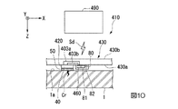
各歪検出ユニット80は、図10に示すように、歪検出部460と、無線送信部81と、バッテリ82と、を備える。
As shown in FIG. 10, each
第一実施形態と同様に、センサ本体部420は、可撓性を有する伸縮配線40を備える。配線403a、配線403bは、伸縮配線40の端部40a、端部40bにそれぞれ電気的に接続されている。
歪検出部460とセンサ本体部420とは、伸縮基板430内又は伸縮基板430の基板面430aに配線された配線403a及び配線403bによって電気的に接続されて、伸縮配線40の端部40aと端部40bとの間の電気抵抗を検出する。
Similar to the first embodiment, the sensor
The
歪検出部460は、歪を常時検出してもよいし、必要な時だけ検出してもよい。
The
無線送信部81は、歪検出部460と通信可能なように電線や光ファイバー等で接続されており、歪検出部460で検出された歪に相当する信号を受け取る。歪検出部460で検出された歪に基づく情報を処理部490に無線で送信する。本実施形態では、無線送信部81は、歪検出部460で検出された歪に相当する信号を受け取り、当該歪に相当する信号Sdに変換する。変換された信号Sdは、無線送信部81によって、処理部490に送信される。送信される信号Sdは、検出された歪に相関した信号であればどのような信号でもよく、アナログ方式でも、デジタル方式でも、どちらの方式でもよい。また、送信形態は光、電波、電磁波等どのような通信形態でもよい。
このとき、検出された歪に基づく情報がどの歪検出ユニット80からの情報かを識別できるように、各無線送信部81は、自身が設けられている歪検出ユニット80の識別情報を、検出された歪に基づく情報と併せて処理部490に送る。
The
At this time, each
バッテリ82は、無線送信部81及び歪検出部460に必要な電力を供給する。バッテリ82によって無線送信部81や歪検出部460に必要な電力を供給すれば、電力の供給配線を設ける必要がないため、コンクリート構造物1の表面1aに対して歪センサ410を任意の場所に設置することができる。
本実施形態では各歪検出ユニット80がバッテリ82を備えているが、変形例として各歪検出ユニット80にバッテリ82を設けずに、いくつかの歪検出ユニット80毎にバッテリを設け、一つのバッテリからいくつかの歪検出ユニット80に電力を供給してもよい。
電力の供給配線の敷設に困難がない場合は、バッテリではなく電力の供給配線によって、複数の歪検出ユニット80に電力を供給してもよい。
The
In this embodiment, each
If there is no difficulty in laying the power supply wiring, the power may be supplied to the plurality of
処理部490は、各歪検出ユニット80から送られてきた検出された歪に基づく情報及び歪検出ユニット80の識別情報を取集し、作業者に提供する。
本実施形態では、処理部490には、歪検出ユニット80の識別情報と各歪検出ユニット80が設置された位置との関係がデータとして予め記憶されている。処理部490は、当該記憶された関係から、歪検出ユニット80の識別情報を用いて、検出された歪に基づく情報とコンクリート構造物1の表面1aの位置とを関連付ける。
したがって、検出された歪に基づく情報とコンクリート構造物1の表面1aの位置とを関連付けることによって、処理部490は、各歪検出ユニット80から送られてきた情報から、コンクリート構造物1の表面1aの歪のマップデータを作成する。
作成されたマップデータは、処理部490によって、表示、印刷等によって出力され、作業者に提示される。作業者に提示されるマップデータは、歪と位置との関係を等高線やカラーマップで示される。
本実施形態では、作業者は、当該マップデータからコンクリート構造物1の表面1a又は内部の歪を把握し、ひび割れの補修や保守を行うことができる。
本実施形態において、任意の場所で検出された歪に基づく情報を確認できるように、処理部490としてノートパソコン、PDA、タブレット等の携帯端末を用いている。
The
In the present embodiment, the
Therefore, by associating the information based on the detected strain with the position of the
The created map data is output by display, printing, etc. by the
In this embodiment, the operator can grasp the
In the present embodiment, a portable terminal such as a notebook computer, a PDA, or a tablet is used as the
本実施形態の歪センサ410のさらなる作用、効果について説明する。
本実施形態では、1つのセンサ本体部420及び1つの歪検出ユニット80の複数の対を伸縮基板430全体にわたって格子状に並べているので、センサ本体部420は、コンクリート構造物1の表面1aにおける格子状の各点についての歪を検出することができる。したがって、コンクリート構造物1の表面1aに沿って、歪の二次元分布を測定することができる。
また、本実施形態では、伸縮基板430及び伸縮配線40を用いることによって、コンクリート構造物1の表面1aに大きな歪が発生した後も、歪に対して耐性を有するため、コンクリート構造物1の表面1aの歪の長期的な監視が可能である。加えて、無線による歪の情報取得が可能であるため、処理部490さえ近くにあれば、作業者は、長期にわたって検出現場に赴くことなく、コンクリート構造物1の表面1aの歪や当該歪のマップデータを、任意の場所で監視することができる。
また、処理部490を携帯端末とすれば、処理部490で歪箇所を確認しながら、ひび割れの発生ありと判断された現場やひび割れの進展ありと判断された現場へ向かうことができるため、ひび割れの補修や保守の作業効率が高まる。
Further actions and effects of the
In the present embodiment, since a plurality of pairs of one sensor
In the present embodiment, by using the
Further, if the
さらに、本実施形態の歪センサ410は、処理部490とは無線である。また、伸縮基板430は、可撓性を有するシートで構成されている。
したがって、例えばトンネルの内壁表面に歪センサ410を設置する場合、トンネル内に図9のような歪センサ410だけを持っていき、トンネル内壁に接着剤、ピン、又はステープルで貼り付けるだけで、歪センサ410の設置が完了するため、歪センサ410の設置が簡単である。
Furthermore, the
Therefore, for example, when the
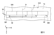
変形例として、図11に示す歪センサ510のように、複数のセンサ本体部520に対して1つの無線送信部581を備えるものとしてもよい。
この場合、無線送信部581は、各歪検出部560と通信可能なように電線や光ファイバー等の通信経路583で接続され、各歪検出部560から検出された歪に相当する信号を受け取る。本変形例では、図11に示すように、バッテリ82を複数の歪検出部560及び無線送信部581に対しそれぞれ設け、複数の歪検出部560及び無線送信部581に電力を供給している。さらなる変形例として無線送信部581だけにバッテリ82を設けて、無線送信部581から各歪検出部560に電力を供給するものであってもよい。
また、図11のように、複数のセンサ本体部520を、予想されるひび割れの発生間隔で、隙間なく敷き詰めれば、ひび割れCrを極力漏れないように検出することも可能である。
As a modification, a single
In this case, the
In addition, as shown in FIG. 11, if a plurality of sensor
「構造物歪検出方法」
以下、本発明の構造物歪検出方法の実施形態について、図12を参照して説明する。
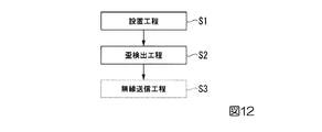
本実施形態は、図12に示す各工程が実施される。本実施形態の歪センサのいずれかを、コンクリート構造物1に適用することによって、実施される。
"Structure strain detection method"
Hereinafter, an embodiment of the structural strain detection method of the present invention will be described with reference to FIG.
In this embodiment, each process shown in FIG. 12 is performed. This is implemented by applying any one of the strain sensors of the present embodiment to the concrete structure 1.
まず、歪センサをコンクリート構造物1の表面1aに設置する(S1:設置工程)。
次に、伸縮配線の歪を検出する(S2:歪検出工程)。
検出した歪は、歪検出部においてそのまま表示、印刷等によって出力され、作業者に提示されてもよいが、本実施形態では、さらに、検出された歪に基づく情報を処理部に無線送信する工程を設けている(S3:無線送信工程)。
検出された歪に基づく情報は、処理部において表示、印刷等によって出力され、作業者に提示される。
First, a strain sensor is installed on the
Next, the strain of the expansion / contraction wiring is detected (S2: strain detection step).
The detected distortion may be output by display, printing or the like as it is in the distortion detection unit and presented to the operator. In the present embodiment, further, a step of wirelessly transmitting information based on the detected distortion to the processing unit (S3: wireless transmission step).
Information based on the detected distortion is output by display, printing or the like in the processing unit and presented to the operator.
「歪の検出結果」
図13に本実施形態によって検出された歪の検出結果を示す。
図13は、横軸に時間T、縦軸に歪センサで検出されたコンクリート構造物1の表面1aの歪εを示す。
時間T=0において、歪ε=0であった歪が、時間とともに連続的に大きくなっていることが分かる。そして、不連続点Qcにおいて、歪εが急に大きくなっている。
このような不連続点Qcは、コンクリート構造物1の表面又は内部のひび割れの発生や進展により発生するものである。
したがって、不連続点Qcを検出することによって、ひび割れの発生やひび割れの進展を判断できる。不連続点は、歪の時間微分値をとり、当該時間微分値をしきい値で検出することによって判定することができる。
"Distortion detection results"
FIG. 13 shows the detection result of the distortion detected by this embodiment.
FIG. 13 shows time T on the horizontal axis and strain ε of the
It can be seen that at time T = 0, the strain that was strain ε = 0 continuously increased with time. At the discontinuous point Qc, the strain ε suddenly increases.
Such a discontinuous point Qc is generated by the occurrence or development of cracks on the surface or inside of the concrete structure 1.
Therefore, by detecting the discontinuous point Qc, it is possible to determine the occurrence of cracks and the progress of cracks. A discontinuous point can be determined by taking a time differential value of strain and detecting the time differential value with a threshold value.
以上、本発明の実施の形態について図面を参照して詳述したが、具体的な構成は上記実施形態に限られるものではなく、本発明の要旨を逸脱しない範囲の設計変更等も含まれる。 As mentioned above, although embodiment of this invention was explained in full detail with reference to drawings, the specific structure is not restricted to the said embodiment, The design change etc. of the range which does not deviate from the summary of this invention are included.
伸縮配線を構成する材料としては、上記以外の材料を使用することが可能である。具体的には、導電性材料として、金属系粒子、金属酸化物系粒子、導電性高分子、カーボン系粒子、イオン液体の1種類又は複数種類を用いて伸縮配線を構成することも可能である。粒子形状には、球、フレーク、ロッド、ワイヤ、ファイバー、ナノチューブなどが挙げられる。カーボン系粒子には、カーボンナノチューブ、カーボンファイバー、グラファイト、グラフェン、フラーレン、カーボンブラック等が挙げられる。使用できる金属としては、金、銀、銅、パラジウム、白金、ニッケルなどの、1種類または複数の金属が挙げられる。
導電性材料をポリフッ化ビニリデン、ポリウレタン、シリコーン、スチレンブタジエンゴム、クロロプレンゴム、アクリルゴム、エポキシなどの1種類又は複数種類の樹脂をバインダー材料と混ぜ合わせた複合材料として伸縮配線形成を構成することも可能である。
伸縮基板を構成する伸縮性を有する材料には、ポリフッ化ビニリデン、ポリウレタン、シリコーン、スチレンブタジエンゴム、クロロプレンゴム、アクリルゴム、エポキシ、ポリイミド、ポリエチレンテレフタレート、ポリエチレンナフタレート、ポリ塩化ビニル、テキスタイル等が挙げられる。
Materials other than those described above can be used as the material constituting the stretchable wiring. Specifically, as the conductive material, one or more kinds of metal-based particles, metal oxide-based particles, conductive polymer, carbon-based particles, and ionic liquids can be used to form the stretchable wiring. . Particle shapes include spheres, flakes, rods, wires, fibers, nanotubes and the like. Examples of the carbon-based particles include carbon nanotubes, carbon fibers, graphite, graphene, fullerene, and carbon black. Examples of the metal that can be used include one or more metals such as gold, silver, copper, palladium, platinum, and nickel.
It is also possible to form stretchable wiring as a composite material in which one or more kinds of resin such as polyvinylidene fluoride, polyurethane, silicone, styrene butadiene rubber, chloroprene rubber, acrylic rubber, epoxy, etc. are mixed with binder material. Is possible.
Examples of the stretchable material constituting the stretchable substrate include polyvinylidene fluoride, polyurethane, silicone, styrene butadiene rubber, chloroprene rubber, acrylic rubber, epoxy, polyimide, polyethylene terephthalate, polyethylene naphthalate, polyvinyl chloride, and textiles. It is done.
第二実施形態では、コーティング層41/伸縮配線40/基板層131(シリコーン/銀ナノワイヤを含む複合材/ポリイミド)の3層構造としているが、変形例としてコーティング層を設けず、配線層/基板層/基板層、例えば、銀ナノワイヤを含む複合材/ポリウレタン/布としてもよい。さらなる変形例として、コーティング層/配線層/基板層/基板層、例えばシリコーン/銀ナノワイヤを含む複合材/シリコーン/布としてもよい。さらに銀ナノワイヤを含む複合材に代えて、カーボンナノワイヤを含む複合材、又は銀ナノワイヤ及びカーボンナノワイヤを含む複合材を用いてもよい。
In the second embodiment, the coating layer 41 /
また、本実施形態では、伸縮配線の両端部の間の電気抵抗を検出しているが、伸縮配線のコンダクタンスを検出するものであってもよい。 Moreover, in this embodiment, although the electrical resistance between the both ends of an expansion wiring is detected, you may detect the conductance of an expansion wiring.
本実施形態では、各伸縮基板に複数のセンサ本体部を並べて配列しているが、伸縮基板の基板面のサイズを各センサ本体部の大きさとし、各伸縮基板にセンサ本体部を一つだけ設けるようにしてもよい。 In the present embodiment, a plurality of sensor main bodies are arranged side by side on each stretchable substrate, but the size of the substrate surface of the stretchable substrate is the size of each sensor main body, and only one sensor main body is provided on each stretchable substrate. You may do it.
本実施形態の歪センサは、コンクリート構造物に限らず、構造物であればどのようなものでも適用可能である。鋼構造物、セラミック構造物、ガラス構造物などに適用することも可能である。
また、本実施形態の歪センサは、トンネルに限らず、例えば、橋梁、橋脚、ダム、鉄塔、機械設備(発電所、変電所等)など、あらゆる構造物に適用することも可能である。
The strain sensor of the present embodiment is not limited to a concrete structure, and any structure can be applied as long as it is a structure. The present invention can also be applied to steel structures, ceramic structures, glass structures, and the like.
In addition, the strain sensor of the present embodiment is not limited to a tunnel, and can be applied to any structure such as a bridge, a pier, a dam, a steel tower, and mechanical equipment (such as a power plant and a substation).
1:コンクリート構造物
1a:表面
3a:配線
3b:配線
5:歪測定システム
10:歪センサ
20:センサ本体部
30:伸縮基板
30a:基板面
40:伸縮配線
40a:端部
40b:端部
40′:伸縮配線
40a′:端部
40b′:端部
41:コーティング層
42a:脚部
42b:脚部
50:接着剤
60:歪検出部
80:歪検出ユニット
81:無線送信部
82:バッテリ
90:処理部
105:歪測定システム
110:歪センサ
120:センサ本体部
130:伸縮基板
130a:基板面
131:基板層
132:粘着層
133a:コンタクト部
133b:コンタクト部
134a:導通部
134b:導通部
240:伸縮配線
240a:端部
240b:端部
340:伸縮配線
340a:端部
340b:端部
403a:配線
403b:配線
405:歪測定システム
410:歪センサ
420:センサ本体部
430:伸縮基板
430a:基板面
460:歪検出部
490:処理部
510:歪センサ
520:センサ本体部
560:歪検出部
581:無線送信部
583:通信経路
Sd:信号
1:
Claims (9)
基板面に沿う方向に伸縮性を有する伸縮基板と、
導電性を有し、前記基板面に沿う方向に延びるように配線され、前記基板面に沿う方向に伸縮性を有する伸縮配線と、を備える歪センサ。 A strain sensor for detecting a strain on a surface of a structure,
An elastic substrate having elasticity in a direction along the substrate surface;
A strain sensor comprising: an electrically conductive conductive wire extending in a direction along the substrate surface, and an elastic wire extending in a direction along the substrate surface.
請求項1から7のいずれかに記載の歪センサを構造物に設置する設置工程と、
前記伸縮配線の歪を検出する歪検出工程と、を実施する構造物歪検出方法。 A structure distortion detection method comprising:
An installation step of installing the strain sensor according to claim 1 on a structure;
And a strain detection step of detecting strain of the stretchable wiring.
Priority Applications (1)
| Application Number | Priority Date | Filing Date | Title |
|---|---|---|---|
| JP2016137169A JP6875672B2 (en) | 2016-07-11 | 2016-07-11 | Structure strain sensor and structure strain detection method |
Applications Claiming Priority (1)
| Application Number | Priority Date | Filing Date | Title |
|---|---|---|---|
| JP2016137169A JP6875672B2 (en) | 2016-07-11 | 2016-07-11 | Structure strain sensor and structure strain detection method |
Publications (2)
| Publication Number | Publication Date |
|---|---|
| JP2018009820A true JP2018009820A (en) | 2018-01-18 |
| JP6875672B2 JP6875672B2 (en) | 2021-05-26 |
Family
ID=60993760
Family Applications (1)
| Application Number | Title | Priority Date | Filing Date |
|---|---|---|---|
| JP2016137169A Active JP6875672B2 (en) | 2016-07-11 | 2016-07-11 | Structure strain sensor and structure strain detection method |
Country Status (1)
| Country | Link |
|---|---|
| JP (1) | JP6875672B2 (en) |
Cited By (3)
| Publication number | Priority date | Publication date | Assignee | Title |
|---|---|---|---|---|
| JP2021117032A (en) * | 2020-01-23 | 2021-08-10 | 大日本印刷株式会社 | Sensor module |
| KR20220077497A (en) * | 2020-12-02 | 2022-06-09 | 연세대학교 산학협력단 | Mechanochromic sensors and uses thereof |
| JP2023161341A (en) * | 2022-04-25 | 2023-11-07 | 国立大学法人九州工業大学 | A mechanical quantity sensor, a robot having the same, a method for sensing a mechanical quantity, and a method for manufacturing a mechanical quantity sensor |
Citations (19)
| Publication number | Priority date | Publication date | Assignee | Title |
|---|---|---|---|---|
| JP2003207399A (en) * | 2002-01-11 | 2003-07-25 | Ishida Co Ltd | Load cell |
| JP2006250647A (en) * | 2005-03-09 | 2006-09-21 | Jfe Koken Corp | Wire cable, and tension measurement system and method |
| JP2006268393A (en) * | 2005-03-24 | 2006-10-05 | Hitachi Ltd | Structure safety monitoring system |
| JP2007108073A (en) * | 2005-10-14 | 2007-04-26 | Railway Technical Res Inst | Ground stress measuring device and ground stress measuring method |
| JP2008150867A (en) * | 2006-12-18 | 2008-07-03 | Tokyo Seiko Co Ltd | High energy absorbing rockfall protection fence |
| WO2009096419A1 (en) * | 2008-01-28 | 2009-08-06 | Kuraray Co., Ltd. | Flexible deformation sensor |
| JP2009244206A (en) * | 2008-03-31 | 2009-10-22 | Nissha Printing Co Ltd | Pressure sensitive sensor |
| US20100090299A1 (en) * | 2008-10-15 | 2010-04-15 | Industrial Technology Research Institute | Flexible electronics for pressure device and fabrication method thereof |
| JP2011197001A (en) * | 2010-03-18 | 2011-10-06 | Korea Research Inst Of Standards & Science | Flexible force or pressure sensor array using semiconductor strain gauge, manufacturing method of flexible force or pressure sensor array, and force or pressure measurement method using flexible force or pressure sensor array |
| JP2012071098A (en) * | 2010-08-31 | 2012-04-12 | Tokai Rubber Ind Ltd | Seat and wheelchair |
| US20130031987A1 (en) * | 2009-12-30 | 2013-02-07 | Jacques Beauvais | Carbon nanotubes based sensing elements and system for monitoring and mapping force, strain and stress |
| JP2013134208A (en) * | 2011-12-27 | 2013-07-08 | Nec Corp | Pressure sensitive element containing carbon nanotube |
| JP2013185966A (en) * | 2012-03-08 | 2013-09-19 | Takano Co Ltd | Surface pressure sensor |
| JP2013542523A (en) * | 2010-10-12 | 2013-11-21 | ニューヨーク・ユニバーシティ | Apparatus for sensing using tiles, sensor with a series of plates, object identification and method for multi-touch surfaces |
| US20140109695A1 (en) * | 2012-10-22 | 2014-04-24 | The Board Of Trustees Of The Leland Stanford Junior University | Nanostructures with strain-induced resistance |
| JP2014528079A (en) * | 2011-09-24 | 2014-10-23 | プレジデント・アンド・フェロウズ・オブ・ハーバード・カレッジ | Artificial skin and elastic strain sensor |
| JP2014228454A (en) * | 2013-05-24 | 2014-12-08 | 株式会社フジクラ | Pressure sensor |
| JP2016057113A (en) * | 2014-09-08 | 2016-04-21 | 公立大学法人大阪府立大学 | Tactile sensor and integration sensor |
| JP2016121975A (en) * | 2014-12-25 | 2016-07-07 | ヤマハ株式会社 | Distortion detection sensor element and external force detection array module |
-
2016
- 2016-07-11 JP JP2016137169A patent/JP6875672B2/en active Active
Patent Citations (19)
| Publication number | Priority date | Publication date | Assignee | Title |
|---|---|---|---|---|
| JP2003207399A (en) * | 2002-01-11 | 2003-07-25 | Ishida Co Ltd | Load cell |
| JP2006250647A (en) * | 2005-03-09 | 2006-09-21 | Jfe Koken Corp | Wire cable, and tension measurement system and method |
| JP2006268393A (en) * | 2005-03-24 | 2006-10-05 | Hitachi Ltd | Structure safety monitoring system |
| JP2007108073A (en) * | 2005-10-14 | 2007-04-26 | Railway Technical Res Inst | Ground stress measuring device and ground stress measuring method |
| JP2008150867A (en) * | 2006-12-18 | 2008-07-03 | Tokyo Seiko Co Ltd | High energy absorbing rockfall protection fence |
| WO2009096419A1 (en) * | 2008-01-28 | 2009-08-06 | Kuraray Co., Ltd. | Flexible deformation sensor |
| JP2009244206A (en) * | 2008-03-31 | 2009-10-22 | Nissha Printing Co Ltd | Pressure sensitive sensor |
| US20100090299A1 (en) * | 2008-10-15 | 2010-04-15 | Industrial Technology Research Institute | Flexible electronics for pressure device and fabrication method thereof |
| US20130031987A1 (en) * | 2009-12-30 | 2013-02-07 | Jacques Beauvais | Carbon nanotubes based sensing elements and system for monitoring and mapping force, strain and stress |
| JP2011197001A (en) * | 2010-03-18 | 2011-10-06 | Korea Research Inst Of Standards & Science | Flexible force or pressure sensor array using semiconductor strain gauge, manufacturing method of flexible force or pressure sensor array, and force or pressure measurement method using flexible force or pressure sensor array |
| JP2012071098A (en) * | 2010-08-31 | 2012-04-12 | Tokai Rubber Ind Ltd | Seat and wheelchair |
| JP2013542523A (en) * | 2010-10-12 | 2013-11-21 | ニューヨーク・ユニバーシティ | Apparatus for sensing using tiles, sensor with a series of plates, object identification and method for multi-touch surfaces |
| JP2014528079A (en) * | 2011-09-24 | 2014-10-23 | プレジデント・アンド・フェロウズ・オブ・ハーバード・カレッジ | Artificial skin and elastic strain sensor |
| JP2013134208A (en) * | 2011-12-27 | 2013-07-08 | Nec Corp | Pressure sensitive element containing carbon nanotube |
| JP2013185966A (en) * | 2012-03-08 | 2013-09-19 | Takano Co Ltd | Surface pressure sensor |
| US20140109695A1 (en) * | 2012-10-22 | 2014-04-24 | The Board Of Trustees Of The Leland Stanford Junior University | Nanostructures with strain-induced resistance |
| JP2014228454A (en) * | 2013-05-24 | 2014-12-08 | 株式会社フジクラ | Pressure sensor |
| JP2016057113A (en) * | 2014-09-08 | 2016-04-21 | 公立大学法人大阪府立大学 | Tactile sensor and integration sensor |
| JP2016121975A (en) * | 2014-12-25 | 2016-07-07 | ヤマハ株式会社 | Distortion detection sensor element and external force detection array module |
Cited By (5)
| Publication number | Priority date | Publication date | Assignee | Title |
|---|---|---|---|---|
| JP2021117032A (en) * | 2020-01-23 | 2021-08-10 | 大日本印刷株式会社 | Sensor module |
| JP7367932B2 (en) | 2020-01-23 | 2023-10-24 | 大日本印刷株式会社 | sensor module |
| KR20220077497A (en) * | 2020-12-02 | 2022-06-09 | 연세대학교 산학협력단 | Mechanochromic sensors and uses thereof |
| KR102472718B1 (en) * | 2020-12-02 | 2022-12-01 | 연세대학교 산학협력단 | Mechanochromic sensors and uses thereof |
| JP2023161341A (en) * | 2022-04-25 | 2023-11-07 | 国立大学法人九州工業大学 | A mechanical quantity sensor, a robot having the same, a method for sensing a mechanical quantity, and a method for manufacturing a mechanical quantity sensor |
Also Published As
| Publication number | Publication date |
|---|---|
| JP6875672B2 (en) | 2021-05-26 |
Similar Documents
| Publication | Publication Date | Title |
|---|---|---|
| Zymelka et al. | Printed strain sensor array for application to structural health monitoring | |
| Chen et al. | A Single-material-printed, Low-cost design for a Carbon-based fabric strain sensor | |
| Ha et al. | Highly sensitive and selective multidimensional resistive strain sensors based on a stiffness-variant stretchable substrate | |
| Dinh et al. | Advances in rational design and materials of high‐performance stretchable electromechanical sensors | |
| US20220221355A1 (en) | Sensing fibers for structural health monitoring | |
| TW201709038A (en) | Three-dimensional touch device | |
| US20170030784A1 (en) | Printed Circuits With Embedded Strain Gauges | |
| Li et al. | Full fabric sensing network with large deformation for continuous detection of skin temperature | |
| JP6875672B2 (en) | Structure strain sensor and structure strain detection method | |
| Gul et al. | Bioinspired interfacial engineering for highly stretchable electronics | |
| CN104406559B (en) | A landslide horizontal displacement vertical distribution sensor assembly and using method | |
| CN109946000A (en) | A dot matrix flexible pressure distribution sensing device and its pressure positioning method | |
| US20220268647A1 (en) | Pressure-sensitive sheet and modular system including the same | |
| Lee et al. | A highly sensitive bending sensor based on controlled crack formation integrated with an energy harvesting pyramid layer | |
| Ma et al. | Large area and flexible flexion sensing matrix for detection of strain distribution in bendable and curved surface | |
| Liu et al. | Experimentally and numerically validated analytical solutions to nonbuckling piezoelectric serpentine ribbons | |
| WO2018021315A1 (en) | Wiring sheet, sheet-shaped system, and structure operation support system | |
| CN102305587A (en) | Surface deformation distribution test sensing element | |
| KR101694215B1 (en) | A soft sensor for deformation measurement | |
| CN118129598B (en) | Method and system for monitoring real-time deformation of shield tail of shield tunneling machine | |
| DeGraff et al. | Scalable and passive carbon nanotube thin-film sensor for detecting micro-strains and potential impact damage in fiber-reinforced composite materials | |
| CN109341909B (en) | A multifunctional flexible stress sensor | |
| CN103954385A (en) | Wireless passive rfid stress sensor | |
| CN113670371B (en) | Intelligent monitoring device and evaluation method for health state of airport pavement structure | |
| CN205562090U (en) | Pressure sensor |
Legal Events
| Date | Code | Title | Description |
|---|---|---|---|
| A521 | Request for written amendment filed |
Free format text: JAPANESE INTERMEDIATE CODE: A523 Effective date: 20160825 |
|
| A521 | Request for written amendment filed |
Free format text: JAPANESE INTERMEDIATE CODE: A523 Effective date: 20170126 |
|
| RD03 | Notification of appointment of power of attorney |
Free format text: JAPANESE INTERMEDIATE CODE: A7423 Effective date: 20190118 |
|
| A621 | Written request for application examination |
Free format text: JAPANESE INTERMEDIATE CODE: A621 Effective date: 20190617 |
|
| A131 | Notification of reasons for refusal |
Free format text: JAPANESE INTERMEDIATE CODE: A131 Effective date: 20200310 |
|
| A521 | Request for written amendment filed |
Free format text: JAPANESE INTERMEDIATE CODE: A523 Effective date: 20200427 |
|
| A131 | Notification of reasons for refusal |
Free format text: JAPANESE INTERMEDIATE CODE: A131 Effective date: 20200804 |
|
| A521 | Request for written amendment filed |
Free format text: JAPANESE INTERMEDIATE CODE: A523 Effective date: 20200917 |
|
| A02 | Decision of refusal |
Free format text: JAPANESE INTERMEDIATE CODE: A02 Effective date: 20201027 |
|
| A521 | Request for written amendment filed |
Free format text: JAPANESE INTERMEDIATE CODE: A523 Effective date: 20210108 |
|
| C60 | Trial request (containing other claim documents, opposition documents) |
Free format text: JAPANESE INTERMEDIATE CODE: C60 Effective date: 20210108 |
|
| A911 | Transfer to examiner for re-examination before appeal (zenchi) |
Free format text: JAPANESE INTERMEDIATE CODE: A911 Effective date: 20210121 |
|
| C21 | Notice of transfer of a case for reconsideration by examiners before appeal proceedings |
Free format text: JAPANESE INTERMEDIATE CODE: C21 Effective date: 20210126 |
|
| A131 | Notification of reasons for refusal |
Free format text: JAPANESE INTERMEDIATE CODE: A131 Effective date: 20210302 |
|
| A521 | Request for written amendment filed |
Free format text: JAPANESE INTERMEDIATE CODE: A523 Effective date: 20210319 |
|
| TRDD | Decision of grant or rejection written | ||
| A01 | Written decision to grant a patent or to grant a registration (utility model) |
Free format text: JAPANESE INTERMEDIATE CODE: A01 Effective date: 20210406 |
|
| A61 | First payment of annual fees (during grant procedure) |
Free format text: JAPANESE INTERMEDIATE CODE: A61 Effective date: 20210414 |
|
| R150 | Certificate of patent or registration of utility model |
Ref document number: 6875672 Country of ref document: JP Free format text: JAPANESE INTERMEDIATE CODE Ref document number: 6875672 Country of ref document: JP Free format text: JAPANESE INTERMEDIATE CODE: R150 |
|
| R250 | Receipt of annual fees |
Free format text: JAPANESE INTERMEDIATE CODE: R250 |
|
| R250 | Receipt of annual fees |
Free format text: JAPANESE INTERMEDIATE CODE: R250 |
|
| R250 | Receipt of annual fees |
Free format text: JAPANESE INTERMEDIATE CODE: R250 |