JP2006250647A - Wire cable, and tension measurement system and method - Google Patents
Wire cable, and tension measurement system and method Download PDFInfo
- Publication number
- JP2006250647A JP2006250647A JP2005066128A JP2005066128A JP2006250647A JP 2006250647 A JP2006250647 A JP 2006250647A JP 2005066128 A JP2005066128 A JP 2005066128A JP 2005066128 A JP2005066128 A JP 2005066128A JP 2006250647 A JP2006250647 A JP 2006250647A
- Authority
- JP
- Japan
- Prior art keywords
- optical fiber
- wire cable
- fiber sensor
- tension
- light
- Prior art date
- Legal status (The legal status is an assumption and is not a legal conclusion. Google has not performed a legal analysis and makes no representation as to the accuracy of the status listed.)
- Pending
Links
Images


Abstract
Description
本発明は、構造物を支持するワイヤケーブル、特に橋梁のワイヤケーブル並びに、このケーブルを使用した張力測定システム及び張力測定方法に関する。 The present invention relates to a wire cable for supporting a structure, particularly a wire cable for a bridge, and a tension measuring system and a tension measuring method using the cable.
ワイヤケーブルである部材を支持する構造物に関し、このワイヤケーブルの張力を測定する手法として、従来から様々な手法が試みられてきた。例えば、ワイヤケーブルに歪ゲージを貼り付け、歪ゲージの出力に基づいてワイヤケーブルの張力を求める手法は、その代用的なものである。最近では、振動法と呼ばれる手法で張力の測定を行うことが主流である。 With respect to a structure that supports a member that is a wire cable, various methods have conventionally been tried as a method for measuring the tension of the wire cable. For example, a technique of attaching a strain gauge to a wire cable and obtaining the tension of the wire cable based on the output of the strain gauge is an alternative. Recently, it is the mainstream to measure tension by a technique called vibration method.
この振動法とは、例えば、特許文献1に示されているように、ワイヤケーブルに所定の振動を作用させ、弦の振動に関する微分方程式を利用して、ワイヤケーブルの固有振動数から張力を求める方法である。 This vibration method is, for example, as shown in Patent Document 1, in which a predetermined vibration is applied to a wire cable, and the tension is obtained from the natural frequency of the wire cable using a differential equation relating to the vibration of the string. Is the method.
しかし、測定の対象が橋梁のワイヤケーブルである場合、交通事情の関係上、張力を測定するチャンスが限られてしまう。このため、歪ゲージを使用する手法では、橋梁の架設時を除けば、橋梁の一斉点検時等、ごく僅かチャンスしかない。 However, when the object of measurement is a wire cable of a bridge, the chance of measuring the tension is limited due to traffic conditions. For this reason, with the technique using strain gauges, there are only a few chances, such as during a simultaneous inspection of a bridge, except when a bridge is installed.
また、振動法は、上述のように、ケーブルの固有振動数から間接的に張力を求める手法であるため、振動法で求めた張力と実際の張力と間にどうしても誤差が出てしまう。 In addition, as described above, the vibration method is a method for indirectly obtaining the tension from the natural frequency of the cable, so an error is inevitably generated between the tension obtained by the vibration method and the actual tension.
本発明は、このような問題点に鑑みてなされたものであり、正確な張力を所望の時に得られるワイヤケーブル、並びに張力測定システム及び張力測定方法を提供することを目的とする。 The present invention has been made in view of such problems, and an object of the present invention is to provide a wire cable, a tension measurement system, and a tension measurement method that can obtain accurate tension at a desired time.
本発明では、上記の課題を解決するために、次の解決手段を採用した。 In the present invention, in order to solve the above-mentioned problems, the following solution means is adopted.
第1に採用したのは、複数の素線を相互に縒り合わせて形成されたワイヤケーブルであって、このワイヤケーブルの軸方向の歪を検出する歪検出手段が、当該ワイヤケーブルに組み込まれ、前記歪検出手段が光ファイバーからなる光ファイバーセンサであり、この光ファイバーセンサが、前記ワイヤケーブルの伸縮に伴って変形するよう前記ワイヤケーブルに組み込まれ、前記光ファイバーセンサの変形により、入射された光の周波数の変化、もしくは光の反射、屈折又は干渉を検知するワイヤケーブルである。 The first adopted is a wire cable formed by twisting together a plurality of strands, and a strain detection means for detecting axial strain of the wire cable is incorporated in the wire cable, The strain detection means is an optical fiber sensor made of an optical fiber, and this optical fiber sensor is incorporated in the wire cable so as to be deformed as the wire cable expands and contracts, and the frequency of the incident light is changed by the deformation of the optical fiber sensor. A wire cable that detects changes or reflection, refraction, or interference of light.
かかるワイヤケーブルに関し、本発明では、前記素線の中の1本に、その軸方向に沿って形成された挿入孔を形成し、前記光ファイバーセンサを前記挿入孔に挿入させて、その軸方向が前記素線の伸縮と共に伸縮されるように構成した。 With regard to such a wire cable, in the present invention, an insertion hole formed along the axial direction is formed in one of the strands, the optical fiber sensor is inserted into the insertion hole, and the axial direction is It was configured to expand and contract with the expansion and contraction of the strands.
第2に採用したのは、構造物を構成する部材を一定の姿勢に支持し、複数の素線を相互に縒り合わせて形成されたワイヤケーブルの張力を測定する張力測定システムであって、前記ワイヤケーブルに組み込まれ、前記ワイヤケーブルの歪を検出する歪検出手段と、前記歪検出手段の検出に基づいて前記ワイヤケーブルに作用する張力を算出する張力演算手段と、前記歪検出手段の検出を前記歪検出手段から前記張力演算手段まで送信する信号通信手段とを備え、前記信号通信手段が、光ファイバーケーブルであり、前記歪検出手段が、光ファイバケーブルの一部を利用して形成された光ファイバーセンサであり、この光ファイバーセンサが、前記ワイヤケーブルの伸縮に伴って変形するよう前記ワイヤケーブルに組み込まれ、前記光ファイバーセンサの変形によって、この光ファイバーセンサに入射された光の周波数の変化、もしくは光の反射、屈折又は干渉を検知して、前記張力演算手段では、前記光ファイバーセンサの検知内容に基づいて、前記ワイヤケーブルの張力を算出する張力測定システムである。 Secondly, a tension measuring system for measuring the tension of a wire cable formed by supporting a member constituting a structure in a fixed posture and twisting a plurality of strands to each other, A strain detection unit that is incorporated in the wire cable and detects strain of the wire cable; a tension calculation unit that calculates a tension acting on the wire cable based on detection of the strain detection unit; and detection of the strain detection unit An optical fiber formed by using a part of the optical fiber cable, the signal communication means being an optical fiber cable, and transmitting the signal from the strain detection means to the tension calculating means. This optical fiber sensor is incorporated in the wire cable so as to deform as the wire cable expands and contracts, and the optical fiber A change in the frequency of light incident on the optical fiber sensor or reflection, refraction, or interference of light is detected by deformation of the sensor, and the tension calculation means detects the wire cable based on the detection content of the optical fiber sensor. It is the tension measurement system which calculates the tension | tensile_strength of.
そして、第3に、構造物を構成する部材を一定の姿勢に支持し、複数の素線を相互に縒り合わせて形成されたワイヤケーブルの張力を測定するにあたり、光ファイバケーブルの一部を利用して形成された光ファイバーセンサを前記ワイヤケーブルに組み込み、前記ワイヤケーブルの伸縮に伴って、前記光ファイバーセンサを変形せしめ、この変形に伴って発生する、前記光ファイバーセンサに入射された光の周波数の変化、もしくは光の反射、屈折又は干渉を検知し、検知された光の周波数の変化、もしくは光の反射、屈折又は干渉に基づいて、張力演算手段により前記ワイヤケーブルの張力を算出する張力測定方法を採用した。 Thirdly, a part of the optical fiber cable is used to measure the tension of the wire cable formed by supporting the members constituting the structure in a fixed posture and twisting the strands together. The optical fiber sensor formed as described above is incorporated into the wire cable, the optical fiber sensor is deformed as the wire cable expands and contracts, and the change in the frequency of light incident on the optical fiber sensor is generated along with the deformation. Or a tension measuring method that detects reflection, refraction, or interference of light and calculates the tension of the wire cable by a tension calculation means based on a change in the detected frequency of light, or reflection, refraction, or interference of light. Adopted.
本発明によれば、ワイヤケーブルの張力を測定する場合に、ワイヤケーブルに生ずる歪から直接張力を測定できる。このため、測定結果と、実際にワイヤケーブルに発生している張力との間に誤差が生じることを極力抑えることが可能となり、正確な値を測定できる。 According to the present invention, when the tension of a wire cable is measured, the tension can be directly measured from the strain generated in the wire cable. For this reason, it becomes possible to suppress the occurrence of an error between the measurement result and the tension actually generated in the wire cable as much as possible, and an accurate value can be measured.
また、歪測定手段として光ファイバーセンサを使用するため、既に通信網として設けられている光ファイバーケーブルを通信手段として利用することができる。これにより、測定の対象となる構造物とは遠隔地にある、例えば、測定機器を設けたベース地やオフィスビルからでも測定することが可能となる。 Further, since the optical fiber sensor is used as the strain measuring means, an optical fiber cable already provided as a communication network can be used as the communication means. As a result, it is possible to perform measurement even from a base site or an office building that is remote from the structure to be measured, for example, a measuring device.
特に、測定の対象が橋梁の支柱と床版とを接続するワイヤケーブルである場合、交通の関係上、現場での測定が制限されてしまう。しかし、本発明によれば、遠隔地から測定することができるため、交通に左右されず、いつでも所望の時にワイヤケーブルの張力を測定できる。 In particular, when the object of measurement is a wire cable that connects a bridge column and a floor slab, measurement on site is limited due to traffic. However, according to the present invention, since it can be measured from a remote place, the tension of the wire cable can be measured at any time regardless of traffic.
さらには、光ファイバー通信網を利用することで、複数の構造物について、一箇所で集中管理を行うこともできる。 Furthermore, by using an optical fiber communication network, centralized management can be performed at a single location for a plurality of structures.
以下、本発明の実施の形態について図面を参照しながら説明する。 Hereinafter, embodiments of the present invention will be described with reference to the drawings.
図1は、本発明の一実施形態にかかる斜張橋用ケーブルとして使用されるワイヤケーブル13の張力測定システムの概略を示している。この張力測定システムは、ワイヤケーブル13に組み込まれる光ファイバーセンサ3と、測定に必要な種々の制御並びに演算処理などを行うコンピュータ7等の設けられたオフィスビル20と、光ファイバーセンサ3の組み込まれた橋梁10と、オフィスビル20とを連絡する通信網としての光ファイバーケーブル2とを備えている。
FIG. 1 schematically shows a tension measurement system for a
図2に示すように、橋梁10は、床版12の延びる方向に関して、一定の間隔毎に、支柱11を備えており、各支柱11毎に、床版12と支柱11とは、複数のワイヤケーブル13で接続されている。これらワイヤケーブル13は、支柱11を軸にして床版12の延びる方向について対称となるように、支柱11と床版12とを斜めに結んでいる。本張力測定システムは、このワイヤケーブル13の張力を測定の対象とするものである。
As shown in FIG. 2, the
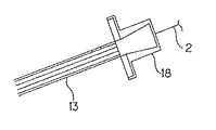
図3は、支柱11とワイヤケーブル13の連結部分の一つを拡大して示した図である。
FIG. 3 is an enlarged view of one of the connecting portions of the
支柱11の上部には、高さ方向に並べられるようにして複数の保持ブラケット14が固定されており、各ワイヤケーブル13の先端は、相互に対向されるようにして支柱11に保持される。この保持ブラケット14は、支柱11に固定される固定面15と、固定面15の前後両側から相互に斜め上方に延びて末広がり状に形成された保持面16とから構成されている。保持面16には、通し孔がそれぞれ形成されており、傾斜橋用ケーブルの先端がこの通り孔に通されて、当該保持ブラケット14に保持される。
A plurality of holding brackets 14 are fixed to the upper portion of the
更に、支柱11の前面及び後面には斜め下方に向けて突出する筒状のケーブルガイド17が設けられている。ケーブルガイド17の中心には、このケーブルガイド17を軸方向に貫通する貫通孔が形成されており、この貫通孔に斜めに延びるワイヤケーブル13が通される。このケーブルガイド17は、床版12から支柱11に向けて延びているワイヤケーブル13を保持ブラケット14に向けて案内している。
Further, a cylindrical cable guide 17 that protrudes obliquely downward is provided on the front and rear surfaces of the
一方、ワイヤケーブル13の先端には、エンドソケット18が設けられている。このエンドソケット18は、フランジのように、ワイヤケーブル13の半径方向外側に向けて張り出しており、保持ブラケット14の通り孔に通されたワイヤケーブル13が保持ブラケット14から抜け出すことを防止するストッパとして機能する。
On the other hand, an
このようにして設けられたワイヤケーブル13には、図4に示すように、先端部分に光ファイバーケーブル2の先端が組み込まれている。この光ファイバーケーブル2の先端部分は、光ファイバーセンサ3として形成されている。
As shown in FIG. 4, the tip of the
図5及び図6は、光ファイバーセンサ3の組み込まれたワイヤケーブル13の先端部分を模型的に拡大して示したものの一例である。
FIGS. 5 and 6 are examples of an enlarged model of the tip of the
ワイヤケーブル13は、鋼線からなる複数の素線23を相互に縒り合わせて一本のケーブルとして構成されたものである。そして、この斜張橋ケーブルを構成する素線23のうち、中央に位置してねじりのない素線23には、その端部から軸方向に延びる挿入孔25が形成されている。この挿入孔25には、光ファイバーセンサ3が挿入される。挿入された光ファイバーセンサ3は、後に説明する回析格子4を間に挟んだ軸方向の両側が挿入孔25に固着され、素線23の軸方向の伸縮に伴って、これと一体的に伸縮するよう構成されている。
The
なお、光ファイバーセンサ3は、図7及び図8に示すようにしてワイヤケーブル13の先端に組み込んでも良い。この実施の形態では、光ファイバーセンサ3はワイヤケーブル13を構成する素線23と素線23の間に挿入されて、素線23に挟持されるようにしてワイヤケーブル13の先端に組み込まれている。この場合にも、光ファイバーセンサ3は、回析格子4を間に挟んだ軸方向の両側が素線23に固着され、素線23の軸方向の伸縮に伴い、これと一体的に伸縮するように構成されている。
The
ここで、この張力測定システムで使用される光ファイバーセンサ3の原理について説明する。
Here, the principle of the
一般に、光ファイバーセンサ3には、(1)波長の変化を利用するFBG(Fiber Bragg Grating)、(2)ブリルアン散乱光の周波数利用するBOTDR(Brillouin Optical Time Domain Reflectmeter)、(3)光の干渉という性質を利用するSOFO(Surveillanced’Ouvrages par Fibres Optiques)、(4)伝送される光の、光ファイバーケーブル2の曲げ損失を利用するOSMOS(Optical Stand Monitoring System)など、様々な性質を使用したものがある。
In general, the
この張力測定システムに使用する光ファイバーセンサ3としては、FBG式光ファイバーセンサを用いることが最適であるが、これらのいずれのものを使用してもよい。
As the
図9は、FBG式光ファイバーセンサ3の概要を模型的に示した図である。この光ファイバーセンサ3には、光を反射させる回析格子4が形成されている。この回析格子4は、光ファイバーセンサ3の軸方向に微小な間隔dを空けて配された一対の格子40により構成されていている。
FIG. 9 is a diagram schematically showing the outline of the FBG type
この回析格子4を備えた光ファイバーセンサ3が軸方向に関してεだけ歪むと、これに伴い格子間隔dも変化するよう構成されている。
When the
かかる回析格子4は、光ファイバーケーブル2に入射された入射光の内、特定の周波数を有する入射光だけを反射させる一方で、それ以外の周波数の光をそのまま通過させる特性を備えている。
The
ここで、回析格子4により反射される特定の周波数を有する入射光の波長λを次の式1で表す。なお、式1において、nはコア部の平均屈折率、dは格子間隔である。
Here, the wavelength λ of the incident light having a specific frequency reflected by the
λ=2nd・・・・(式1) λ = 2nd (Formula 1)
そして、光ファイバーセンサ3が軸方向にεだけひずんで、格子間隔dが変化すると、当該回析格子4により反射される入射光の波長は、入射光に対して反射光の波長は式2に表すように変化する。
When the
Δλ=λ(1−P)ε・・・・(式2)
なお、Pはポアソン比を表す。
Δλ = λ (1-P) ε (Expression 2)
P represents the Poisson's ratio.
この光ファイバーセンサ3では、波長の変化を測定することで、光ファイバーセンサ3の取り付けられた対象物の歪、張力を測定することを可能ならしめている。なお、波長は、光ファイバーセンサ3の歪に対して直線性を示す。波長の変化量は入射光の波長にもよるが、約1.2×10⁻¹²m/μStrain程度である。
In the
かかるFBGが当該システムには最も適している。しかし、上述のように、BOTDR、SOFO、OSMOSを使用することができる。以下、これらの手法について、その原理を簡単に説明する。 Such an FBG is most suitable for the system. However, as described above, BOTDR, SOFO, and OSMOS can be used. Hereinafter, the principle of these methods will be briefly described.
BOTDRとは、ブリルアン散乱光が光ファイバーの歪変化に対して直線的に周波数変化を発生させるという「歪依存性」を利用するものである。 BOTDR uses “strain dependency” in which Brillouin scattered light causes a frequency change linearly with respect to a change in strain of an optical fiber.
図10に歪依存性をイメージしたものを、図11に直線性をイメージしたものをそれぞれ図示する。図10に示すように、光ファイバーに張力が加わり、歪が発生すると、ブリルアン散乱光のスペクトル分布により周波数のピークがシフトする。また、例えば、波長λ=1.55μmの入射光の歪依存性による周波数シフトの直線性を図示すると、図11のようになる。 FIG. 10 illustrates a distortion image, and FIG. 11 illustrates a linearity image. As shown in FIG. 10, when tension is applied to the optical fiber and distortion occurs, the frequency peak shifts due to the spectral distribution of the Brillouin scattered light. Further, for example, the linearity of the frequency shift due to the strain dependency of the incident light having the wavelength λ = 1.55 μm is shown in FIG.
このように、ブリルアン散乱光の周波数と歪との関係は、直線性を有しているため、ブリルアン散乱光の周波数のシフト量を計測することで歪測定に適用できる。 Thus, since the relationship between the frequency of Brillouin scattered light and strain has linearity, it can be applied to strain measurement by measuring the frequency shift amount of Brillouin scattered light.
このBOTDRは、分布型センサとして使用することができる。即ち、光ファイバーにパルス波を入射し、戻ってきた後方散乱光としてのブリルアン散乱光の戻り時間、強さ
を計測する。なお、この時間から戻ってきた散乱光データの計測位置までの距離Lは、次の式3で得られる。
This BOTDR can be used as a distributed sensor. That is, a pulse wave is incident on the optical fiber, and the return time and intensity of the Brillouin scattered light as the back scattered light that has returned are measured. The distance L to the measurement position of the scattered light data returned from this time can be obtained by the
L=CT/2n・・・・(式3)
C:光の速度
T:検出するまでの時間
n:光ファイバーの屈折率
L = CT / 2n (Expression 3)
C: Speed of light
T: Time until detection
n: Refractive index of optical fiber
そして、入射光の周波数を漸次変化させながら、同様の計測を実施することで、ブリルアン散乱光の周波数シフトのスペクトル分布が距離別に求められる。図12は、そのイメージを図示したものである。 Then, by performing the same measurement while gradually changing the frequency of the incident light, the spectrum distribution of the frequency shift of the Brillouin scattered light is obtained for each distance. FIG. 12 illustrates the image.
例えば、ある位置の歪値を知りたいとき、その位置までの各距離の部分の周波数分布から歪を求める。この図12に示す例では、Z1の位置から図を右斜め上に横切ったときのスペクトル分からシフト量を求めて、歪に変換する。かかる作業を各距離ごとに行い、連続した歪分布を求める。 For example, when it is desired to know the distortion value at a certain position, the distortion is obtained from the frequency distribution of each distance portion to that position. In the example shown in FIG. 12, the shift amount is obtained from the spectrum when the figure is crossed diagonally right upward from the position of Z1, and converted into distortion. This operation is performed for each distance to obtain a continuous strain distribution.
図中ε1、ε2の各歪値がΔLの長さごとに求められる。このΔLの長さは、cを係数、入射するパルス幅をωとすると次の式4で表すことができる。
In the figure, the strain values of ε1 and ε2 are obtained for each length of ΔL. The length of ΔL can be expressed by the following
ΔL=cω/2n・・・・(式4) ΔL = cω / 2n (Expression 4)
この分解能はΔLは、入射されたパルス光のパルス幅の両サイドから散乱光がある角度を持って伝搬する。そして、2つの散乱光が一直線上に重なり合ったときには、2つの散乱光は分離されない。よって、これら2つ(パルス幅の両サイド)を距離に換算した長さ分の中で歪値は計測される。 In this resolution, ΔL propagates at a certain angle from both sides of the pulse width of the incident pulsed light. And when two scattered lights overlap on a straight line, two scattered lights are not isolate | separated. Therefore, the distortion value is measured in the length corresponding to the distance between these two (both sides of the pulse width).
次に、SOFOの原理について説明する。 Next, the principle of SOFO will be described.
図13及び図14は、SOFO式の光ファイバーセンサを使用した場合の原理を模型的に示したものである。 13 and 14 schematically show the principle when a SOFO type optical fiber sensor is used.
このSOFO式の光ファイバーセンサ50は、図13に示すように、2本の光ファイバー53,54が使用される。一方は測定用光ファイバー53で、他方は参照用光ファイバー54である。これら2本の光ファイバー53,54は、この光ファイバーセンサ50と接続されているカプラ56で分岐され、この光ファイバーセンサ50の軸方向に所定間隔を空けて配された一対の固定部52により平行をなすようにして固定されている。そして、これら2本の光ファイバー53,54の先端には鏡55が接続されている。固定部52間は、可動部51である。測定用光ファイバー53は、プレテンションが付与されている一方で、参照用光ファイバー54は、螺旋状に巻かれて配されている。
The SOFO type
このSOFO式の光ファイバーセンサ50では、可動部51に変位が生じると、測定用光ファイバー53の長さが変化する。ただし、参照用光ファイバー54の長さは不変である。
In this SOFO type
図14は、このSOFO式の光ファイバーセンサ50とリーディングユニット60とを光ファイバーケーブル71及び中継ボックス70で接続してSOFOシステムを完成させた1例を示している。
FIG. 14 shows an example in which the SOFO system
このSOFOシステムによれば、まず光源としてのLED64から白色光が、コネクタ68、光ファイバーケーブル71、中継ボックス70を介して各光ファイバーセンサ50へ送られる。各光ファイバーセンサ50へ送られた光は、それぞれの光ファイバーセンサ50のカプラ56により、測定用光ファイバー53と参照用光ファイバー54とに分岐される。そして、先端に設けられた鏡55に反射されて、再びカプラ56に集光され、リーディングユニットに戻される。
According to this SOFO system, first, white light is sent from the
この際、測定用光ファイバー53と参照用光ファイバー54との長さが異なる(元の長さの差+可動部の変位量)ので、戻された光には干渉が生じる。そこで、リーディングユニット60の内部に配されたカプラ62により、リーディングユニット60に内蔵された固定部65と可動部66に分光する。そして、固定部65と可動部66にそれぞれ設けられた鏡67で反射させてピーク干渉位置を見出す。ただし、光ファイバーセンサ50内部の2本の光ファイバー53,54の長さの違い等に関する補正をこのとき行う。
At this time, since the measurement optical fiber 53 and the reference optical fiber 54 are different in length (original length difference + displacement amount of the movable portion), interference occurs in the returned light. Therefore, the light is split into the fixed portion 65 and the movable portion 66 built in the reading unit 60 by the
以上のようにして、光ファイバーセンサ50の可動部51において発生した変位量を、光の干渉としてとらえ、これを測定する手法が、SOFOシステムである。なお、具体的なデータ解析を行うために、パソコン61がPD63を介してカプラ62と接続されている。また、モデム69を使用して通信手段と接続させることで、遠隔地でのデータ分析を行うこともできる。
The SOFO system is a method for measuring the displacement amount generated in the movable portion 51 of the
最後に、OSMOSの原理について説明する。 Finally, the principle of OSMOS will be described.
このOSMOSは、光の曲げ損失(マイクロベンディング)という考え方を適用したセンサである。 The OSMOS is a sensor to which the concept of light bending loss (microbending) is applied.
光の屈折について、屈折率の大きなコアIIから小さなグラッドIに光が入射する態様を考えると、図15に示す3態様が考えられる。 As regards the light refraction, considering the manner in which light is incident on the small grad I from the core II having a large refractive index, the three embodiments shown in FIG.
Aの態様は、光A1がθAの角度で入射し、屈折角θA2で屈折する屈折光A2と、角度θAで反射する反射光A3に分かれる場合である。 A mode A is a case where the light A1 is incident at an angle of θA and is divided into a refracted light A2 that is refracted at a refraction angle θA2 and a reflected light A3 that is reflected at an angle θA.
Bの態様は、光の入射角がθBというある角度になり、屈折角θB2が90度となり、光は境界面に沿って進む場合である。なお、このときの入射角θBを臨界角という。 In the mode B, the incident angle of light is a certain angle θB, the refraction angle θB2 is 90 degrees, and the light travels along the boundary surface. The incident angle θB at this time is called a critical angle.
そして、Cの態様は、入射角θCが臨界角以上の場合である。この場合には、光は屈折することなく、全反射を起こし、すべて反射光C2となる。 And the aspect of C is a case where incident angle (theta) C is more than a critical angle. In this case, the light is not refracted but undergoes total reflection, and all becomes reflected light C2.
光ファイバーではCの態様のように、全反射しながら光が伝搬する。光の曲げ損失は、入射角が臨界角以下になった時に発生する。図16は、この概念を示すものである。光ファイバーに光が入射されると、光は全反射しながらコアの内部を伝搬する。そして、光がこの図16に示すように曲げ部分に到達すると、入射角が小さくなる部分が発生し、コアの外に放射する光が生じる。この損失量は、光の曲率半径Rに依存する。 In the optical fiber, light propagates with total reflection as in the case of C. Bending loss of light occurs when the incident angle becomes less than the critical angle. FIG. 16 illustrates this concept. When light enters the optical fiber, the light propagates through the core while being totally reflected. When the light reaches the bent portion as shown in FIG. 16, a portion having a small incident angle is generated, and light radiated out of the core is generated. This loss amount depends on the radius of curvature R of the light.
OSMOSは、この損失を測定することで、歪を測定するものである。 OSMOS measures distortion by measuring this loss.
本発明では、これらのいずれの方式をも使用することできるが、以下では、再び図1〜図9を参照しながらFBG式光ファイバーセンサ3を使用した場合を例に説明する。
In the present invention, any of these methods can be used. In the following, the case where the FBG type
光ファイバーセンサ3は、上述のように、光ファイバーケーブル2の先端部が加工されたものである。当該光ファイバーセンサ3を備えた光ファイバーケーブル2は、一般の通信網として設けられ、橋梁10と、オフィスビル20とを連絡している。
The
オフィスビル20には、光学部6と、この光学部6と接続されたコンピュータ7とが設けられている。光学部6は、光ファイバーケーブル2を介して光ファイバーセンサ3へ所定の波長を有する光を入射させる光源、光ファイバーセンサ3から反射された光を受光する受光部、受光部で受光された光を所定の電気信号に変換するインターフェイス等の機能を有し、当該光学部6で張力の測定を行っている。
The
この光学部6と接続されたコンピュータ7は、光学部6に対して測定開始・終了等の指令を発信するコントローラとして機能すると共に、光学部6で得られた測定データを所望の形に加工したり、測定データを記録媒体に記録する等、データ処理部としても機能する。
The
この光学部6では、光ファイバーケーブル2を介して光ファイバーセンサ3から送信された反射光の信号に基づき、光ファイバーセンサ3で検知した波長の変化に基づき、ワイヤケーブル13の歪を算出する。そして、算出された歪に基づき、応力、張力を算出している。
The optical unit 6 calculates the distortion of the
なお、光学部6が、一定の時間毎にトリガを発生せしめ、トリガが立つ毎に測定を繰り返すようにシステム設計をしておけば、対象となるワイヤケーブル13の張力が時間の経過と共にどのように変化するのかを自動的に測定することができる。
If the system is designed so that the optical unit 6 generates a trigger at regular time intervals and repeats the measurement every time the trigger is raised, how does the tension of the
以上の構成を備えた、張力測定システムによれば、次の手順によりワイヤケーブル13の張力は測定される。
According to the tension measurement system having the above configuration, the tension of the
まず、光学部6から光ファイバーケーブル2に光を入射させる。入射光は、この光ファイバーケーブル2を伝達して、橋梁10まで到達する。光ファイバーケーブル2の先端は、上述のように、光ファイバーセンサ3として加工されており、橋梁10のワイヤケーブル13の先端に組み込まれているので、最終的はワイヤケーブル13の先端に入射光は到達する。そして、この光ファイバーセンサ3に到達した入射光のうち、特定の周波数の入射光は、この回析格子4により反射される。
First, light enters the
ここで、ワイヤケーブル13は、予め一定の張力がかけられた状態で、支柱11と床版12とを接続しているので、ワイヤケーブル13は延び方向に歪が発生している。そして、光ファイバーセンサ3は、このワイヤケーブル13の歪と一体に歪むように、素線23に固着されているので、光ファイバーセンサ3も同様に延びる方向に歪んでいる。このため、回析格子4を構成する格子40の間隔dは、光ファイバーセンサ3が無負荷の状態よりも広げられている。
Here, since the
かかる回析格子4により入射光が反射されると、格子間隔の変化に伴って、入射光の波長λもΔλだけ変化する。
When incident light is reflected by the
波長の変化した反射光は、再び、通信網としての光ファイバーケーブル2を通って、オフィスビル20に設けられた光学部6により受光される。光学部6は、受光した反射光の波長と入射光の波長とから波長の変化Δλを測定し、これに基づき歪を算出する。そして、算出された歪から、応力、張力が算出される。
The reflected light with the changed wavelength is again received by the optical unit 6 provided in the
算出された張力は、光学部6に接続されたコンピュータ7により、グラフ化されたり、所定のフォーマットのデータシートに記録されるなど、所望の形式に加工される。また、算出されたデータを記録媒体に記録させて、データの保管等も行う。この際、光学部6とコンピュータ7の役割分担としては、光学部6では、単に波長の変化Δλのみを測定し、その後の処理をコンピュータ7で行うようにしても構わない。なお、データ処理及びの保管は、橋梁10に設けられた複数のワイヤケーブル13毎に行えば、どのワイヤケーブル13に異常が発生したのかを即時に特定でき、迅速な対応を採ることができる。さらには、橋梁10に設けられたすべての支柱11に対して測定を行えば、橋梁10全体を常に監視の基に置くことができる。
The calculated tension is processed into a desired format, such as graphed or recorded on a data sheet of a predetermined format, by a
以上、一箇所に架設された、橋梁10にのみ当該張力測定システムを適用した場合について説明したが、通信網としての光ファイバーケーブル2が延びている地域に架設された橋梁10であれば、一箇所のオフィスビル20で複数の橋梁10のワイヤケーブル13の測定を同時に行うことができる。
As described above, the case where the tension measurement system is applied only to the
以上、光ファイバーセンサをワイヤケーブルの素線の内部に組み込む等、ワイヤケーブルの外縁より内側の位置に光ファイバーケーブルを埋め込むようにして設けたものについて説明したが、光ファイバーケーブルをワイヤケーブルの表面部分に張り付けて設けてもよい。 The optical fiber sensor has been described so as to be embedded inside the outer edge of the wire cable, such as by incorporating the optical fiber sensor inside the wire of the wire cable. However, the optical fiber cable is attached to the surface portion of the wire cable. May be provided.
図17は、ワイヤケーブル13のエンドソケット18に、ワイヤケーブル13の軸方向に挿入孔18aを設け、この挿入孔18aから光ファイバーケーブル2を挿入させている。そして、光ファイバーケーブル2の先端に設けられている光ファイバーセンサ3をワイヤケーブル13の外表面と、被覆部13aとの間に配置させ、光ファイバーセンサ3をワイヤケーブル13の外表面に位置する1本の素線23に接着剤で接着させている。そして、外部から被覆材45で光ファイバーセンサー3を覆う。
In FIG. 17, the
このように、ワイヤケーブル13の外表面に光ファイバーセンサ3を接着させても、光ファイバーセンサ3はワイヤケーブル13の歪を検知する。
Thus, even if the
図18及び図19は、ワイヤケーブル13の外表面に光ファイバーセンサ3を接着させる他の実施形態を示している。
18 and 19 show another embodiment in which the
この実施形態では、ワイヤケーブル13のエンドソケット18の近傍にて、被覆部13aの一部に切り込み部49を形成している。この切り込み部49は、被覆部13aの内部に配されたワイヤケーブル13の外表面を部分的に露出させている。光ファイバーセンサ3は、この切り込み部49においてワイヤケーブル13の外表面に位置する素線23に接着される。接着された光ファイバーセンサ3は、外側から被覆材45で覆われる。なお、切り込み部49は、予め被覆部13aに形成しておいてもよいが、現場にて被覆部13aを部分的に切り取って形成してもよい。
In this embodiment, a
この実施形態で使用される光ファイバーセンサ3は、所定の長さに短く切断された光ファイバーケーブル2の先端に接続されている。光ファイバーケーブル2の後端には接続用のコネクタ46が設けられており、通信用の光ファイバーケーブル(不図示)と、当該コネクタ46を介して接続されるよう構成されている。
The
なお、ワイヤケーブル13の外表面に光ファイバーセンサ3を接着させる手法では、ワイヤケーブル13の端部付近に光ファイバーセンサ3を設ける形態には限定されず、ワイヤケーブル13の軸方向におけるいずれの位置にでも設けることができる。
Note that the method of bonding the
この場合、次のようにして光ファイバーセンサ3を設けるとよい。
In this case, the
図20に示す実施形態では、クランプ80を用いている。このクランプ80は、円環状に形成されて、ワイヤケーブルの外周面を被覆する被覆部81と、この被覆部81を半径方向に伸縮せしめる締め込み部82とから構成されている。被覆部81は、半径方向の一部に、所定の隙間を有する軸方向に延びるスリットが形成されている。締め付け部82は、このスリットの幅と同寸の間隔に配された2枚の板材がワイヤケーブル13の半径方向外側に張り出すようにして形成されている。そして、締め付け部82を構成している各板材には、3つの締め付けボルト83がワイヤケーブル13の軸方向に並べられて取り付けられている。
In the embodiment shown in FIG. 20, a
このクランプ80は、締め付けボルト83を締め付けることで、被覆部81に形成されたスリットの幅が狭められ、これにより、ワイヤケーブル13の外周面を締め付けるように構成されている。
The
光ファイバーセンサ3はワイヤケーブル13の外表面に位置する素線に接着され、その外側がクランプ80で覆われる。光ファイバーセンサ3は、外側からクランプ80により締め付けられてワイヤケーブル13の外周面に強固に密着される。これにより剥離が防止され、確実にワイヤケーブル13の歪を検知する。
The
なお、ワイヤケーブル13の外表面に光ファイバーセンサ3を密着させる手段としては、図21に示すようにテーピング85を用いてもよい。
As a means for bringing the
この実施の形態においても、光ファイバーセンサ3をワイヤケーブル13の外表面に位置する素線に接着させている。この接着された光ファイバーセンサ3は、外側から、細長い長方形に形成された板圧の薄い鉄板48で被覆されている。そして、テーピング85がワイヤケーブル13の外周面に巻き付けられ、光ファイバーセンサ3は、鉄板47ごとテーピング85により、ワイヤケーブル13の外周面に密着される。テーピング85は、光ファイバーセンサ3が完全に隠蔽されるように、ワイヤケーブル13の軸方向について鉄板48の長さよりも長い範囲について巻き付けられる。なお、テーピング85は、一般に使用されているビニールテープ、ガムテープなどを用いればよい。
Also in this embodiment, the
2・・・・・・光ファイバーケーブル
3,50・・・光ファイバーセンサ
4・・・・・・回析格子
40・・・・・格子
6・・・・・・光学部
7・・・・・・コンピュータ
10・・・・・橋梁
13・・・・・ワイヤケーブル
23・・・・・素線
25・・・・・挿入孔
2 ....
Claims (4)
このワイヤケーブルの軸方向の歪を検出する歪検出手段が、当該ワイヤケーブルに組み込まれ、
前記歪検出手段が光ファイバーからなる光ファイバーセンサであり、
この光ファイバーセンサが、前記ワイヤケーブルの伸縮に伴って変形するよう前記ワイヤケーブルに組み込まれ、前記光ファイバーセンサの変形により、入射された光の周波数の変化、もしくは光の反射、屈折又は干渉を検知することを特徴とするワイヤケーブル。 A wire cable formed by twisting together a plurality of strands,
The strain detection means for detecting the strain in the axial direction of the wire cable is incorporated in the wire cable,
The strain detection means is an optical fiber sensor comprising an optical fiber,
This optical fiber sensor is incorporated in the wire cable so as to be deformed as the wire cable expands and contracts, and the deformation of the optical fiber sensor detects a change in frequency of incident light, or reflection, refraction, or interference of light. A wire cable characterized by that.
前記ワイヤケーブルに組み込まれ、前記ワイヤケーブルの歪を検出する歪検出手段と、
前記歪検出手段の検出に基づいて前記ワイヤケーブルに作用する張力を算出する張力演算手段と、
前記歪検出手段の検出を前記歪検出手段から前記張力演算手段まで送信する信号通信手段と、を備え、
前記信号通信手段が、光ファイバーケーブルであり、
前記歪検出手段が、光ファイバケーブルの一部を利用して形成された光ファイバーセンサであり、
この光ファイバーセンサが、前記ワイヤケーブルの伸縮に伴って変形するよう前記ワイヤケーブルに組み込まれ、前記光ファイバーセンサの変形によって、この光ファイバーセンサに入射された光の周波数の変化、もしくは光の反射、屈折又は干渉を検知して、
前記張力演算手段では、前記光ファイバーセンサの検知内容に基づいて、前記ワイヤケーブルの張力を算出することを特徴とする張力測定システム。 A tension measuring system that supports members constituting a structure in a fixed posture and measures the tension of a wire cable formed by twisting together a plurality of strands,
A strain detector that is incorporated in the wire cable and detects strain of the wire cable;
A tension calculating means for calculating a tension acting on the wire cable based on the detection of the strain detecting means;
Signal communication means for transmitting detection of the strain detection means from the strain detection means to the tension calculation means,
The signal communication means is an optical fiber cable;
The strain detection means is an optical fiber sensor formed using a part of an optical fiber cable,
This optical fiber sensor is incorporated in the wire cable so as to be deformed as the wire cable expands and contracts, and the deformation of the optical fiber sensor changes the frequency of light incident on the optical fiber sensor, or reflects, refracts or refractions the light. Detect the interference,
The tension measurement system characterized in that the tension calculation means calculates the tension of the wire cable based on the detection content of the optical fiber sensor.
光ファイバケーブルの一部を利用して形成された光ファイバーセンサを前記ワイヤケーブルに組み込み、
前記ワイヤケーブルの伸縮に伴って、前記光ファイバーセンサを変形せしめ、この変形に伴って発生する、前記光ファイバーセンサに入射された光の周波数の変化、もしくは光の反射、屈折又は干渉を検知し、
検知された光の周波数の変化、もしくは光の反射、屈折又は干渉に基づいて、張力演算手段により前記ワイヤケーブルの張力を算出することを特徴とする張力測定方法。 In measuring the tension of a wire cable formed by supporting a member constituting a structure in a fixed posture and twisting a plurality of strands together,
An optical fiber sensor formed using a part of the optical fiber cable is incorporated into the wire cable,
As the wire cable expands and contracts, the optical fiber sensor is deformed, and a change in the frequency of light incident on the optical fiber sensor, or a reflection, refraction, or interference of the light that occurs along with the deformation is detected.
A tension measuring method, comprising: calculating a tension of the wire cable by a tension calculating unit based on a change in a detected frequency of light or reflection, refraction, or interference of light.
Priority Applications (1)
| Application Number | Priority Date | Filing Date | Title |
|---|---|---|---|
| JP2005066128A JP2006250647A (en) | 2005-03-09 | 2005-03-09 | Wire cable, and tension measurement system and method |
Applications Claiming Priority (1)
| Application Number | Priority Date | Filing Date | Title |
|---|---|---|---|
| JP2005066128A JP2006250647A (en) | 2005-03-09 | 2005-03-09 | Wire cable, and tension measurement system and method |
Publications (2)
| Publication Number | Publication Date |
|---|---|
| JP2006250647A true JP2006250647A (en) | 2006-09-21 |
| JP2006250647A5 JP2006250647A5 (en) | 2006-12-07 |
Family
ID=37091322
Family Applications (1)
| Application Number | Title | Priority Date | Filing Date |
|---|---|---|---|
| JP2005066128A Pending JP2006250647A (en) | 2005-03-09 | 2005-03-09 | Wire cable, and tension measurement system and method |
Country Status (1)
| Country | Link |
|---|---|
| JP (1) | JP2006250647A (en) |
Cited By (22)
| Publication number | Priority date | Publication date | Assignee | Title |
|---|---|---|---|---|
| KR20080046046A (en) * | 2006-11-21 | 2008-05-26 | 전남대학교산학협력단 | Earthanchor structure using using optial fiber embeded wire strand and health monitoring method of thereof |
| JP2009162657A (en) * | 2008-01-08 | 2009-07-23 | Railway Technical Res Inst | Strong wind monitoring method and strong wind monitoring device |
| KR100956686B1 (en) * | 2009-07-17 | 2010-05-10 | 전남대학교산학협력단 | Health monitoring method for Bridge structure using optial fiber embeded wire strand |
| KR100956687B1 (en) * | 2009-07-17 | 2010-05-10 | 전남대학교산학협력단 | Health monitoring method of earthanchor structure using optial fiber embeded wire strand |
| KR100965001B1 (en) | 2008-05-27 | 2010-06-21 | 전남대학교산학협력단 | wire strand having sensor unit and production method of thereof |
| CN102162760A (en) * | 2010-12-29 | 2011-08-24 | 中铁大桥局集团武汉桥梁科学研究院有限公司 | Cable force monitoring device for attached-type stay cable |
| EP2484834A1 (en) * | 2009-09-30 | 2012-08-08 | Fasten Group Company Ltd | Bridge intelligent cable system with built-in fiber grating sensor |
| JP2014085181A (en) * | 2012-10-22 | 2014-05-12 | Kobe Steel Ltd | Strain distribution measuring apparatus, strain distribution measuring method, and strain distribution measuring program |
| JP2015520699A (en) * | 2012-05-30 | 2015-07-23 | サイトロニク リミテッドCytroniq., Ltd. | Fuel reduction, safe operation and maintenance information provision system and method through predictive monitoring and predictive control of gas dynamic, hydrodynamic environmental internal and external forces, ship stress, 6-DOF motion and position for real-time offshore structures |
| JP2015155867A (en) * | 2014-02-21 | 2015-08-27 | 住友電工スチールワイヤー株式会社 | Tensile force measuring apparatus |
| JP5879453B1 (en) * | 2015-08-27 | 2016-03-08 | 新日鉄住金エンジニアリング株式会社 | Method of introducing initial tensile strain into cable and optical fiber |
| JP2016057231A (en) * | 2014-09-11 | 2016-04-21 | 鹿島建設株式会社 | Measurement device, strain measurement device, pc steel stranded wire and fiber optic member |
| CN105568856A (en) * | 2015-12-23 | 2016-05-11 | 中铁大桥局集团有限公司 | Synchronous construction method for sparse-cable-stayed bridge cable beam |
| JP2018009820A (en) * | 2016-07-11 | 2018-01-18 | 東京電力ホールディングス株式会社 | Structural strain sensor and method of detecting structural strain |
| JP2018514779A (en) * | 2015-05-08 | 2018-06-07 | フグロ テクノロジー ベー・フェーFugro Technology B.V. | Optical sensor device, sensor device and cable |
| US10370969B2 (en) * | 2014-11-13 | 2019-08-06 | Rock Safety Sweden Ab | Arrangement for rock bolts and a method for the use of the arrangement, and a reinforcement system comprising such an arrangement |
| CN110207876A (en) * | 2019-06-20 | 2019-09-06 | 中船重工海为郑州高科技有限公司 | A kind of Miniature steel wire rope tension sensor |
| RU2717693C1 (en) * | 2019-06-24 | 2020-03-25 | Акционерное общество "Научно-исследовательский и проектно-конструкторский институт информатизации, автоматизации и связи на железнодорожном транспорте" | Artificial structures control and diagnostics system |
| CN111397822A (en) * | 2020-04-11 | 2020-07-10 | 江西驰宇光电科技发展有限公司 | Bridge safety monitoring device and method based on laser gyroscope |
| CN116164626A (en) * | 2023-02-07 | 2023-05-26 | 浙江启明电力集团有限公司 | Cable deformation detection equipment |
| CN117029713A (en) * | 2023-10-08 | 2023-11-10 | 中科航迈数控软件(深圳)有限公司 | Machine tool spindle deformation monitoring system, method, equipment and medium |
| WO2023225316A1 (en) * | 2022-05-19 | 2023-11-23 | Nec Laboratories America, Inc. | Telecom cable tension screening technique based on wave propagation and distributed acoustic sensing |
Citations (4)
| Publication number | Priority date | Publication date | Assignee | Title |
|---|---|---|---|---|
| JPH02228531A (en) * | 1989-01-23 | 1990-09-11 | Felten & Guilleaume Energietechnik Gmbh | Photoconductive liquid-sensor for small tension force or compression force |
| JPH05180713A (en) * | 1992-01-08 | 1993-07-23 | Mitsubishi Heavy Ind Ltd | Cable tension measuring method and device |
| JP2001318011A (en) * | 2000-05-02 | 2001-11-16 | Toa Grout Kogyo Co Ltd | Method of measuring strain or tensile force of tension steel member |
| JP2004512492A (en) * | 1999-05-06 | 2004-04-22 | レイヴ・エリクソン・ニフォテク・アーエス | Cable monitoring system |
-
2005
- 2005-03-09 JP JP2005066128A patent/JP2006250647A/en active Pending
Patent Citations (4)
| Publication number | Priority date | Publication date | Assignee | Title |
|---|---|---|---|---|
| JPH02228531A (en) * | 1989-01-23 | 1990-09-11 | Felten & Guilleaume Energietechnik Gmbh | Photoconductive liquid-sensor for small tension force or compression force |
| JPH05180713A (en) * | 1992-01-08 | 1993-07-23 | Mitsubishi Heavy Ind Ltd | Cable tension measuring method and device |
| JP2004512492A (en) * | 1999-05-06 | 2004-04-22 | レイヴ・エリクソン・ニフォテク・アーエス | Cable monitoring system |
| JP2001318011A (en) * | 2000-05-02 | 2001-11-16 | Toa Grout Kogyo Co Ltd | Method of measuring strain or tensile force of tension steel member |
Cited By (31)
| Publication number | Priority date | Publication date | Assignee | Title |
|---|---|---|---|---|
| KR20080046046A (en) * | 2006-11-21 | 2008-05-26 | 전남대학교산학협력단 | Earthanchor structure using using optial fiber embeded wire strand and health monitoring method of thereof |
| JP2009162657A (en) * | 2008-01-08 | 2009-07-23 | Railway Technical Res Inst | Strong wind monitoring method and strong wind monitoring device |
| KR100965001B1 (en) | 2008-05-27 | 2010-06-21 | 전남대학교산학협력단 | wire strand having sensor unit and production method of thereof |
| KR100956686B1 (en) * | 2009-07-17 | 2010-05-10 | 전남대학교산학협력단 | Health monitoring method for Bridge structure using optial fiber embeded wire strand |
| KR100956687B1 (en) * | 2009-07-17 | 2010-05-10 | 전남대학교산학협력단 | Health monitoring method of earthanchor structure using optial fiber embeded wire strand |
| EP2484834A1 (en) * | 2009-09-30 | 2012-08-08 | Fasten Group Company Ltd | Bridge intelligent cable system with built-in fiber grating sensor |
| EP2484834A4 (en) * | 2009-09-30 | 2014-07-16 | Fasten Group Company Ltd | Bridge intelligent cable system with built-in fiber grating sensor |
| CN102162760A (en) * | 2010-12-29 | 2011-08-24 | 中铁大桥局集团武汉桥梁科学研究院有限公司 | Cable force monitoring device for attached-type stay cable |
| EP2860489A4 (en) * | 2012-05-30 | 2016-07-20 | Cytroniq Co Ltd | System and method for providing information on fuel savings, safe operation, and maintenance by real-time predictive monitoring and predictive controlling of aerodynamic and hydrodynamic environmental internal/external forces, hull stresses, motion with six degrees of freedom, and the location of marine structure |
| JP2015520699A (en) * | 2012-05-30 | 2015-07-23 | サイトロニク リミテッドCytroniq., Ltd. | Fuel reduction, safe operation and maintenance information provision system and method through predictive monitoring and predictive control of gas dynamic, hydrodynamic environmental internal and external forces, ship stress, 6-DOF motion and position for real-time offshore structures |
| EP4239283A3 (en) * | 2012-05-30 | 2023-11-15 | Cytroniq Co., Ltd. | System and method for providing information on fuel savings, safe operation, and maintenance by real-time predictive monitoring and predictive controlling of aerodynamic and hydrodynamic environmental internal/external forces, hull stresses, motion with |
| JP2014085181A (en) * | 2012-10-22 | 2014-05-12 | Kobe Steel Ltd | Strain distribution measuring apparatus, strain distribution measuring method, and strain distribution measuring program |
| JP2015155867A (en) * | 2014-02-21 | 2015-08-27 | 住友電工スチールワイヤー株式会社 | Tensile force measuring apparatus |
| JP2016057231A (en) * | 2014-09-11 | 2016-04-21 | 鹿島建設株式会社 | Measurement device, strain measurement device, pc steel stranded wire and fiber optic member |
| US10370969B2 (en) * | 2014-11-13 | 2019-08-06 | Rock Safety Sweden Ab | Arrangement for rock bolts and a method for the use of the arrangement, and a reinforcement system comprising such an arrangement |
| JP2018514779A (en) * | 2015-05-08 | 2018-06-07 | フグロ テクノロジー ベー・フェーFugro Technology B.V. | Optical sensor device, sensor device and cable |
| JP5879453B1 (en) * | 2015-08-27 | 2016-03-08 | 新日鉄住金エンジニアリング株式会社 | Method of introducing initial tensile strain into cable and optical fiber |
| JP2017044925A (en) * | 2015-08-27 | 2017-03-02 | 新日鉄住金エンジニアリング株式会社 | Cable and method of introducing initial tensile strain to optical fiber |
| US9958299B2 (en) | 2015-08-27 | 2018-05-01 | Nippon Steel & Sumikin Engineering Co., Ltd. | Cable and method for introducing initial tensile strain to optical fiber |
| CN105568856A (en) * | 2015-12-23 | 2016-05-11 | 中铁大桥局集团有限公司 | Synchronous construction method for sparse-cable-stayed bridge cable beam |
| CN105568856B (en) * | 2015-12-23 | 2018-03-30 | 中铁大桥局集团有限公司 | A kind of dilute cable stayed-cable bridge Suo Liang method for synchronously constructing |
| JP2018009820A (en) * | 2016-07-11 | 2018-01-18 | 東京電力ホールディングス株式会社 | Structural strain sensor and method of detecting structural strain |
| CN110207876B (en) * | 2019-06-20 | 2021-07-13 | 中船重工海为郑州高科技有限公司 | Miniature steel wire rope tension sensor |
| CN110207876A (en) * | 2019-06-20 | 2019-09-06 | 中船重工海为郑州高科技有限公司 | A kind of Miniature steel wire rope tension sensor |
| RU2717693C1 (en) * | 2019-06-24 | 2020-03-25 | Акционерное общество "Научно-исследовательский и проектно-конструкторский институт информатизации, автоматизации и связи на железнодорожном транспорте" | Artificial structures control and diagnostics system |
| CN111397822A (en) * | 2020-04-11 | 2020-07-10 | 江西驰宇光电科技发展有限公司 | Bridge safety monitoring device and method based on laser gyroscope |
| WO2023225316A1 (en) * | 2022-05-19 | 2023-11-23 | Nec Laboratories America, Inc. | Telecom cable tension screening technique based on wave propagation and distributed acoustic sensing |
| CN116164626A (en) * | 2023-02-07 | 2023-05-26 | 浙江启明电力集团有限公司 | Cable deformation detection equipment |
| CN116164626B (en) * | 2023-02-07 | 2024-03-26 | 浙江启明电力集团有限公司 | Cable deformation detection equipment |
| CN117029713A (en) * | 2023-10-08 | 2023-11-10 | 中科航迈数控软件(深圳)有限公司 | Machine tool spindle deformation monitoring system, method, equipment and medium |
| CN117029713B (en) * | 2023-10-08 | 2024-02-20 | 中科航迈数控软件(深圳)有限公司 | Machine tool spindle deformation monitoring system, method, equipment and medium |
Similar Documents
| Publication | Publication Date | Title |
|---|---|---|
| JP2006250647A (en) | Wire cable, and tension measurement system and method | |
| US5118931A (en) | Fiber optic microbending sensor arrays including microbend sensors sensitive over different bands of wavelengths of light | |
| JPH0261698B2 (en) | ||
| US8727613B2 (en) | Method and system for measuring a parameter in a high temperature environment using an optical sensor | |
| JP3668199B2 (en) | Tunnel deformation measurement method | |
| EP1124112A2 (en) | Optical fiber sensor | |
| JP2008545124A (en) | Optical strain gauge | |
| KR20100026145A (en) | Method for measuring pre-stress or strain using fiber bragg grating(fbg) sensor | |
| EP2990756B1 (en) | Strain sensor and strain sensor installation method | |
| KR20160122318A (en) | Fiber Optic Interferometric Sensor with FBG for Simultaneous Measurement of Sound, Vibration and Temperature and Method for Sensing thereof | |
| JP2000230935A (en) | Accelerometer and acceleration-measuring apparatus equipped with the same | |
| EP2990755B1 (en) | Strain sensor | |
| JP3860488B2 (en) | Wide-area strain distribution measurement system | |
| JP2012088155A (en) | Measuring method using fbg sensor, and device thereof | |
| EP0086231A1 (en) | Microbending of optical fibers for remote force measurement | |
| CN108139236A (en) | Sensor patch and its method for manufacturing sensor patch | |
| JPH11287650A (en) | Measuring device for deformation of internal space of tunnel by use of optical fiber | |
| JP3544861B2 (en) | Measurement target section identification method | |
| JP2002048517A (en) | Cable for sensing strain, and method of measuring strain | |
| JP2003014561A (en) | Strain sensor and strain sensing unit | |
| JPH11218458A (en) | Pressure sensor and pressure measuring apparatus | |
| US10401573B2 (en) | Affixing fiber optic sensing element to an apparatus | |
| WO2007043716A1 (en) | Optical fiber bragg grating unit and apparatus and method of measuring deformation of structure having the same | |
| KR100965001B1 (en) | wire strand having sensor unit and production method of thereof | |
| JP4824593B2 (en) | Wind monitoring device |
Legal Events
| Date | Code | Title | Description |
|---|---|---|---|
| A521 | Written amendment |
Free format text: JAPANESE INTERMEDIATE CODE: A523 Effective date: 20060922 |
|
| RD01 | Notification of change of attorney |
Free format text: JAPANESE INTERMEDIATE CODE: A7421 Effective date: 20060922 |
|
| A521 | Written amendment |
Free format text: JAPANESE INTERMEDIATE CODE: A821 Effective date: 20060925 |
|
| A621 | Written request for application examination |
Effective date: 20070216 Free format text: JAPANESE INTERMEDIATE CODE: A621 |
|
| A711 | Notification of change in applicant |
Effective date: 20090518 Free format text: JAPANESE INTERMEDIATE CODE: A712 |
|
| A977 | Report on retrieval |
Effective date: 20090717 Free format text: JAPANESE INTERMEDIATE CODE: A971007 |
|
| A131 | Notification of reasons for refusal |
Free format text: JAPANESE INTERMEDIATE CODE: A131 Effective date: 20091013 |
|
| A02 | Decision of refusal |
Free format text: JAPANESE INTERMEDIATE CODE: A02 Effective date: 20100323 |