JP2017536976A - Robot equipment - Google Patents
Robot equipment Download PDFInfo
- Publication number
- JP2017536976A JP2017536976A JP2017522074A JP2017522074A JP2017536976A JP 2017536976 A JP2017536976 A JP 2017536976A JP 2017522074 A JP2017522074 A JP 2017522074A JP 2017522074 A JP2017522074 A JP 2017522074A JP 2017536976 A JP2017536976 A JP 2017536976A
- Authority
- JP
- Japan
- Prior art keywords
- module
- component
- robot
- extension member
- arm
- Prior art date
- Legal status (The legal status is an assumption and is not a legal conclusion. Google has not performed a legal analysis and makes no representation as to the accuracy of the status listed.)
- Pending
Links
- 239000007921 spray Substances 0.000 claims abstract description 203
- 230000007246 mechanism Effects 0.000 claims abstract description 32
- 239000000463 material Substances 0.000 claims abstract description 26
- 238000005507 spraying Methods 0.000 claims abstract description 14
- 230000008878 coupling Effects 0.000 claims description 27
- 238000010168 coupling process Methods 0.000 claims description 27
- 238000005859 coupling reaction Methods 0.000 claims description 27
- 230000004044 response Effects 0.000 claims description 3
- 238000005452 bending Methods 0.000 claims description 2
- 230000005484 gravity Effects 0.000 claims description 2
- 230000001419 dependent effect Effects 0.000 claims 1
- 238000010586 diagram Methods 0.000 description 34
- 210000002310 elbow joint Anatomy 0.000 description 26
- 239000011810 insulating material Substances 0.000 description 15
- 210000003857 wrist joint Anatomy 0.000 description 10
- 230000008602 contraction Effects 0.000 description 9
- 238000007689 inspection Methods 0.000 description 7
- 238000013507 mapping Methods 0.000 description 5
- 230000008901 benefit Effects 0.000 description 4
- 239000003795 chemical substances by application Substances 0.000 description 4
- 238000004891 communication Methods 0.000 description 4
- 238000013461 design Methods 0.000 description 4
- 238000000034 method Methods 0.000 description 4
- 239000003973 paint Substances 0.000 description 4
- 210000000707 wrist Anatomy 0.000 description 4
- 238000009413 insulation Methods 0.000 description 3
- 230000008569 process Effects 0.000 description 3
- 230000002829 reductive effect Effects 0.000 description 3
- 239000007779 soft material Substances 0.000 description 3
- 230000000007 visual effect Effects 0.000 description 3
- 239000011248 coating agent Substances 0.000 description 2
- 239000000417 fungicide Substances 0.000 description 2
- 210000001503 joint Anatomy 0.000 description 2
- 238000012423 maintenance Methods 0.000 description 2
- 230000000704 physical effect Effects 0.000 description 2
- 229920002635 polyurethane Polymers 0.000 description 2
- 239000004814 polyurethane Substances 0.000 description 2
- 239000003755 preservative agent Substances 0.000 description 2
- 238000012545 processing Methods 0.000 description 2
- 238000009958 sewing Methods 0.000 description 2
- 229920000742 Cotton Polymers 0.000 description 1
- 240000006829 Ficus sundaica Species 0.000 description 1
- 239000000654 additive Substances 0.000 description 1
- 238000004873 anchoring Methods 0.000 description 1
- 239000010425 asbestos Substances 0.000 description 1
- 239000011230 binding agent Substances 0.000 description 1
- 229920002678 cellulose Polymers 0.000 description 1
- 239000001913 cellulose Substances 0.000 description 1
- 230000008859 change Effects 0.000 description 1
- 238000000576 coating method Methods 0.000 description 1
- 230000000295 complement effect Effects 0.000 description 1
- 238000010276 construction Methods 0.000 description 1
- 230000003247 decreasing effect Effects 0.000 description 1
- 230000002950 deficient Effects 0.000 description 1
- 238000005516 engineering process Methods 0.000 description 1
- 239000012530 fluid Substances 0.000 description 1
- 239000006261 foam material Substances 0.000 description 1
- 230000000855 fungicidal effect Effects 0.000 description 1
- 239000011464 hollow brick Substances 0.000 description 1
- 229910052500 inorganic mineral Inorganic materials 0.000 description 1
- 238000009434 installation Methods 0.000 description 1
- 239000012774 insulation material Substances 0.000 description 1
- 238000011835 investigation Methods 0.000 description 1
- 239000011707 mineral Substances 0.000 description 1
- 230000002093 peripheral effect Effects 0.000 description 1
- 230000035699 permeability Effects 0.000 description 1
- 238000003825 pressing Methods 0.000 description 1
- 239000000047 product Substances 0.000 description 1
- 239000011253 protective coating Substances 0.000 description 1
- 230000008439 repair process Effects 0.000 description 1
- 230000000284 resting effect Effects 0.000 description 1
- 229910052895 riebeckite Inorganic materials 0.000 description 1
- 239000000565 sealant Substances 0.000 description 1
- 125000006850 spacer group Chemical group 0.000 description 1
- 230000003068 static effect Effects 0.000 description 1
- 239000013589 supplement Substances 0.000 description 1
- 238000001356 surgical procedure Methods 0.000 description 1
- 238000012546 transfer Methods 0.000 description 1
- 238000002604 ultrasonography Methods 0.000 description 1
- XLYOFNOQVPJJNP-UHFFFAOYSA-N water Substances O XLYOFNOQVPJJNP-UHFFFAOYSA-N 0.000 description 1
- 238000004078 waterproofing Methods 0.000 description 1
- 239000002023 wood Substances 0.000 description 1
Images


Classifications
-
- B—PERFORMING OPERATIONS; TRANSPORTING
- B25—HAND TOOLS; PORTABLE POWER-DRIVEN TOOLS; MANIPULATORS
- B25J—MANIPULATORS; CHAMBERS PROVIDED WITH MANIPULATION DEVICES
- B25J9/00—Programme-controlled manipulators
- B25J9/08—Programme-controlled manipulators characterised by modular constructions
-
- B—PERFORMING OPERATIONS; TRANSPORTING
- B05—SPRAYING OR ATOMISING IN GENERAL; APPLYING FLUENT MATERIALS TO SURFACES, IN GENERAL
- B05B—SPRAYING APPARATUS; ATOMISING APPARATUS; NOZZLES
- B05B13/00—Machines or plants for applying liquids or other fluent materials to surfaces of objects or other work by spraying, not covered by groups B05B1/00 - B05B11/00
- B05B13/02—Means for supporting work; Arrangement or mounting of spray heads; Adaptation or arrangement of means for feeding work
-
- B—PERFORMING OPERATIONS; TRANSPORTING
- B05—SPRAYING OR ATOMISING IN GENERAL; APPLYING FLUENT MATERIALS TO SURFACES, IN GENERAL
- B05B—SPRAYING APPARATUS; ATOMISING APPARATUS; NOZZLES
- B05B12/00—Arrangements for controlling delivery; Arrangements for controlling the spray area
- B05B12/08—Arrangements for controlling delivery; Arrangements for controlling the spray area responsive to condition of liquid or other fluent material to be discharged, of ambient medium or of target ; responsive to condition of spray devices or of supply means, e.g. pipes, pumps or their drive means
- B05B12/12—Arrangements for controlling delivery; Arrangements for controlling the spray area responsive to condition of liquid or other fluent material to be discharged, of ambient medium or of target ; responsive to condition of spray devices or of supply means, e.g. pipes, pumps or their drive means responsive to conditions of ambient medium or target, e.g. humidity, temperature position or movement of the target relative to the spray apparatus
- B05B12/122—Arrangements for controlling delivery; Arrangements for controlling the spray area responsive to condition of liquid or other fluent material to be discharged, of ambient medium or of target ; responsive to condition of spray devices or of supply means, e.g. pipes, pumps or their drive means responsive to conditions of ambient medium or target, e.g. humidity, temperature position or movement of the target relative to the spray apparatus responsive to presence or shape of target
-
- B—PERFORMING OPERATIONS; TRANSPORTING
- B05—SPRAYING OR ATOMISING IN GENERAL; APPLYING FLUENT MATERIALS TO SURFACES, IN GENERAL
- B05B—SPRAYING APPARATUS; ATOMISING APPARATUS; NOZZLES
- B05B12/00—Arrangements for controlling delivery; Arrangements for controlling the spray area
- B05B12/004—Arrangements for controlling delivery; Arrangements for controlling the spray area comprising sensors for monitoring the delivery, e.g. by displaying the sensed value or generating an alarm
-
- B—PERFORMING OPERATIONS; TRANSPORTING
- B05—SPRAYING OR ATOMISING IN GENERAL; APPLYING FLUENT MATERIALS TO SURFACES, IN GENERAL
- B05B—SPRAYING APPARATUS; ATOMISING APPARATUS; NOZZLES
- B05B13/00—Machines or plants for applying liquids or other fluent materials to surfaces of objects or other work by spraying, not covered by groups B05B1/00 - B05B11/00
- B05B13/005—Machines or plants for applying liquids or other fluent materials to surfaces of objects or other work by spraying, not covered by groups B05B1/00 - B05B11/00 mounted on vehicles or designed to apply a liquid on a very large surface, e.g. on the road, on the surface of large containers
-
- B—PERFORMING OPERATIONS; TRANSPORTING
- B05—SPRAYING OR ATOMISING IN GENERAL; APPLYING FLUENT MATERIALS TO SURFACES, IN GENERAL
- B05B—SPRAYING APPARATUS; ATOMISING APPARATUS; NOZZLES
- B05B13/00—Machines or plants for applying liquids or other fluent materials to surfaces of objects or other work by spraying, not covered by groups B05B1/00 - B05B11/00
- B05B13/02—Means for supporting work; Arrangement or mounting of spray heads; Adaptation or arrangement of means for feeding work
- B05B13/0278—Arrangement or mounting of spray heads
-
- B—PERFORMING OPERATIONS; TRANSPORTING
- B05—SPRAYING OR ATOMISING IN GENERAL; APPLYING FLUENT MATERIALS TO SURFACES, IN GENERAL
- B05B—SPRAYING APPARATUS; ATOMISING APPARATUS; NOZZLES
- B05B13/00—Machines or plants for applying liquids or other fluent materials to surfaces of objects or other work by spraying, not covered by groups B05B1/00 - B05B11/00
- B05B13/02—Means for supporting work; Arrangement or mounting of spray heads; Adaptation or arrangement of means for feeding work
- B05B13/04—Means for supporting work; Arrangement or mounting of spray heads; Adaptation or arrangement of means for feeding work the spray heads being moved during spraying operation
- B05B13/0431—Means for supporting work; Arrangement or mounting of spray heads; Adaptation or arrangement of means for feeding work the spray heads being moved during spraying operation with spray heads moved by robots or articulated arms, e.g. for applying liquid or other fluent material to 3D-surfaces
-
- B—PERFORMING OPERATIONS; TRANSPORTING
- B05—SPRAYING OR ATOMISING IN GENERAL; APPLYING FLUENT MATERIALS TO SURFACES, IN GENERAL
- B05B—SPRAYING APPARATUS; ATOMISING APPARATUS; NOZZLES
- B05B13/00—Machines or plants for applying liquids or other fluent materials to surfaces of objects or other work by spraying, not covered by groups B05B1/00 - B05B11/00
- B05B13/06—Machines or plants for applying liquids or other fluent materials to surfaces of objects or other work by spraying, not covered by groups B05B1/00 - B05B11/00 specially designed for treating the inside of hollow bodies
- B05B13/0627—Arrangements of nozzles or spray heads specially adapted for treating the inside of hollow bodies
-
- B—PERFORMING OPERATIONS; TRANSPORTING
- B05—SPRAYING OR ATOMISING IN GENERAL; APPLYING FLUENT MATERIALS TO SURFACES, IN GENERAL
- B05B—SPRAYING APPARATUS; ATOMISING APPARATUS; NOZZLES
- B05B15/00—Details of spraying plant or spraying apparatus not otherwise provided for; Accessories
- B05B15/60—Arrangements for mounting, supporting or holding spraying apparatus
- B05B15/62—Arrangements for supporting spraying apparatus, e.g. suction cups
- B05B15/628—Arrangements for supporting spraying apparatus, e.g. suction cups of variable length
-
- B—PERFORMING OPERATIONS; TRANSPORTING
- B25—HAND TOOLS; PORTABLE POWER-DRIVEN TOOLS; MANIPULATORS
- B25J—MANIPULATORS; CHAMBERS PROVIDED WITH MANIPULATION DEVICES
- B25J1/00—Manipulators positioned in space by hand
- B25J1/02—Manipulators positioned in space by hand articulated or flexible
-
- B—PERFORMING OPERATIONS; TRANSPORTING
- B25—HAND TOOLS; PORTABLE POWER-DRIVEN TOOLS; MANIPULATORS
- B25J—MANIPULATORS; CHAMBERS PROVIDED WITH MANIPULATION DEVICES
- B25J1/00—Manipulators positioned in space by hand
- B25J1/08—Manipulators positioned in space by hand movably mounted in a wall
-
- B—PERFORMING OPERATIONS; TRANSPORTING
- B25—HAND TOOLS; PORTABLE POWER-DRIVEN TOOLS; MANIPULATORS
- B25J—MANIPULATORS; CHAMBERS PROVIDED WITH MANIPULATION DEVICES
- B25J11/00—Manipulators not otherwise provided for
- B25J11/0075—Manipulators for painting or coating
-
- B—PERFORMING OPERATIONS; TRANSPORTING
- B25—HAND TOOLS; PORTABLE POWER-DRIVEN TOOLS; MANIPULATORS
- B25J—MANIPULATORS; CHAMBERS PROVIDED WITH MANIPULATION DEVICES
- B25J19/00—Accessories fitted to manipulators, e.g. for monitoring, for viewing; Safety devices combined with or specially adapted for use in connection with manipulators
- B25J19/02—Sensing devices
- B25J19/021—Optical sensing devices
- B25J19/023—Optical sensing devices including video camera means
-
- B—PERFORMING OPERATIONS; TRANSPORTING
- B25—HAND TOOLS; PORTABLE POWER-DRIVEN TOOLS; MANIPULATORS
- B25J—MANIPULATORS; CHAMBERS PROVIDED WITH MANIPULATION DEVICES
- B25J5/00—Manipulators mounted on wheels or on carriages
-
- B—PERFORMING OPERATIONS; TRANSPORTING
- B25—HAND TOOLS; PORTABLE POWER-DRIVEN TOOLS; MANIPULATORS
- B25J—MANIPULATORS; CHAMBERS PROVIDED WITH MANIPULATION DEVICES
- B25J9/00—Programme-controlled manipulators
- B25J9/06—Programme-controlled manipulators characterised by multi-articulated arms
-
- B—PERFORMING OPERATIONS; TRANSPORTING
- B25—HAND TOOLS; PORTABLE POWER-DRIVEN TOOLS; MANIPULATORS
- B25J—MANIPULATORS; CHAMBERS PROVIDED WITH MANIPULATION DEVICES
- B25J9/00—Programme-controlled manipulators
- B25J9/06—Programme-controlled manipulators characterised by multi-articulated arms
- B25J9/065—Snake robots
-
- E—FIXED CONSTRUCTIONS
- E04—BUILDING
- E04B—GENERAL BUILDING CONSTRUCTIONS; WALLS, e.g. PARTITIONS; ROOFS; FLOORS; CEILINGS; INSULATION OR OTHER PROTECTION OF BUILDINGS
- E04B1/00—Constructions in general; Structures which are not restricted either to walls, e.g. partitions, or floors or ceilings or roofs
- E04B1/62—Insulation or other protection; Elements or use of specified material therefor
- E04B1/74—Heat, sound or noise insulation, absorption, or reflection; Other building methods affording favourable thermal or acoustical conditions, e.g. accumulating of heat within walls
-
- E—FIXED CONSTRUCTIONS
- E04—BUILDING
- E04F—FINISHING WORK ON BUILDINGS, e.g. STAIRS, FLOORS
- E04F15/00—Flooring
- E04F15/18—Separately-laid insulating layers; Other additional insulating measures; Floating floors
-
- E—FIXED CONSTRUCTIONS
- E04—BUILDING
- E04F—FINISHING WORK ON BUILDINGS, e.g. STAIRS, FLOORS
- E04F21/00—Implements for finishing work on buildings
- E04F21/02—Implements for finishing work on buildings for applying plasticised masses to surfaces, e.g. plastering walls
- E04F21/06—Implements for applying plaster, insulating material, or the like
-
- B—PERFORMING OPERATIONS; TRANSPORTING
- B05—SPRAYING OR ATOMISING IN GENERAL; APPLYING FLUENT MATERIALS TO SURFACES, IN GENERAL
- B05B—SPRAYING APPARATUS; ATOMISING APPARATUS; NOZZLES
- B05B12/00—Arrangements for controlling delivery; Arrangements for controlling the spray area
-
- B—PERFORMING OPERATIONS; TRANSPORTING
- B05—SPRAYING OR ATOMISING IN GENERAL; APPLYING FLUENT MATERIALS TO SURFACES, IN GENERAL
- B05B—SPRAYING APPARATUS; ATOMISING APPARATUS; NOZZLES
- B05B12/00—Arrangements for controlling delivery; Arrangements for controlling the spray area
- B05B12/08—Arrangements for controlling delivery; Arrangements for controlling the spray area responsive to condition of liquid or other fluent material to be discharged, of ambient medium or of target ; responsive to condition of spray devices or of supply means, e.g. pipes, pumps or their drive means
- B05B12/084—Arrangements for controlling delivery; Arrangements for controlling the spray area responsive to condition of liquid or other fluent material to be discharged, of ambient medium or of target ; responsive to condition of spray devices or of supply means, e.g. pipes, pumps or their drive means responsive to condition of liquid or other fluent material already sprayed on the target, e.g. coating thickness, weight or pattern
-
- B—PERFORMING OPERATIONS; TRANSPORTING
- B05—SPRAYING OR ATOMISING IN GENERAL; APPLYING FLUENT MATERIALS TO SURFACES, IN GENERAL
- B05B—SPRAYING APPARATUS; ATOMISING APPARATUS; NOZZLES
- B05B12/00—Arrangements for controlling delivery; Arrangements for controlling the spray area
- B05B12/16—Arrangements for controlling delivery; Arrangements for controlling the spray area for controlling the spray area
- B05B12/18—Arrangements for controlling delivery; Arrangements for controlling the spray area for controlling the spray area using fluids, e.g. gas streams
Abstract
表面上に材料をスプレーする装置は、遠位端及び近位端を有する伸張部材と、所定のスプレーパターンにて材料をスプレーするよう、伸張部材の遠位端に取り付けられ、伸張部材の近位端におけるスプレー材料入口部に結合されるスプレーノズルと、伸張部材の遠位端に取り付けられ、伸張部材の近位端におけるカメラ出力部に結合されてスプレーパターンの画像を取り込むよう構成されたカメラと、伸張部材の近位端から前記スプレーノズルの操作を制御するよう構成された制御機構とを備える。【選択図】図11An apparatus for spraying material onto a surface is attached to the extension member having a distal end and a proximal end and attached to the distal end of the extension member to spray the material in a predetermined spray pattern, proximal of the extension member. A spray nozzle coupled to the spray material inlet at the end; a camera attached to the distal end of the extension member and configured to be coupled to a camera output at the proximal end of the extension member to capture an image of the spray pattern; A control mechanism configured to control operation of the spray nozzle from a proximal end of the extension member. [Selection] Figure 11
Description
本発明は、遠隔操作可能なスプレーノズル、特に閉鎖空間の表面上に処理剤をスプレーするのに好適な電気機械的アームに関する。本発明に係る実施形態は、モジュール型ロボットに関する。 The present invention relates to a remotely operable spray nozzle, in particular an electromechanical arm suitable for spraying a treatment agent on the surface of a closed space. Embodiments according to the present invention relate to a modular robot.
本出願人の先願に係る国際公開第2014/188221号パンフレットは、膨張性の発泡材料をスプレーするためのロボットを開示している。本願は、従来のロボット車両の代替となる電気機械的アームを開示するものである。 International Publication No. 2014/188221 pamphlet of the applicant's prior application discloses a robot for spraying an expandable foam material. The present application discloses an electromechanical arm that is an alternative to a conventional robotic vehicle.
例えば原子炉などの危険な環境下で遠隔操作を行うためにロボットを用い、パイプ内などのアクセスできない領域内で観察及び操作を行い、あるいは、非侵襲性手術用の医療器具として用いることは既知である。このような既知のロボットは、これらの操作を行うのに適するロボットアームを備え、あるいは、ロボットアーム形状を有している。 For example, it is known to use a robot to perform remote operation in a dangerous environment such as a nuclear reactor, perform observation and operation in an inaccessible area such as a pipe, or use as a medical instrument for non-invasive surgery It is. Such a known robot has a robot arm suitable for performing these operations, or has a robot arm shape.
しかしながら、先行技術に属するいくつかのロボットアームには、多くの不利な点がある。例えば、ロボットアームは、通常、既定の長さ又は既定数の継手を備え、あるいは、アームの長さによりモジュールが制限されている場合、モジュールが過大となる又はシステムが作動しなくなる前にアームを伸張させることができる。一般的にアームは、自己完結型ではなく、嵩張る支持構造を有するために設置及び移送の問題が生じ、一人では簡単に取り扱うことができない。ロボットアームが、高度な制御システムを要し、過度に複雑化する傾向にあることで、当面のタスクが複雑なものになる。これによりオペレータが、簡易にタスクを取り上げ、実行することが難しくなる。ロボットアームは、牽引力、パワー及びナビゲーションの問題を生じさせる固有の推進ユニットを要する自己完結型であるか、あるいは、非動力型であるために、対象空間へのアクセスが制限されるアームである。 However, some robot arms belonging to the prior art have many disadvantages. For example, a robotic arm usually has a predetermined length or a predetermined number of joints, or if the module is limited by the length of the arm, the arm can be moved before the module becomes overloaded or the system fails. Can be stretched. In general, the arm is not self-contained and has a bulky support structure, which causes installation and transfer problems and cannot be handled easily by one person. Robotic arms require sophisticated control systems and tend to be overly complex, complicating the task at hand. This makes it difficult for the operator to pick up and execute tasks easily. Robot arms are either self-contained, requiring a unique propulsion unit that creates traction, power and navigation problems, or are non-powered, so that access to the target space is limited.
代替的に、オペレータは、手工具又は動力工具を用いることで、ロボット装置が有しない精密性及び柔軟性を補うことができる。これらの工具は、煙突掃除器又は裁縫器具を点検するためのボロスコープなどに限定されている。これらの工具の長さ、外部機能は限定されており、一般的に視界の直線距離においてのみ使用することができる。 Alternatively, the operator can supplement the precision and flexibility that the robotic device does not have by using hand tools or power tools. These tools are limited to chimney cleaners or boroscopes for inspecting sewing tools. The length and external functions of these tools are limited and can generally be used only at a linear distance of view.
本開示は、少なくともいくつかの実施形態において、先行技術に係る装置の代替となる技術の提供を目的とするものである。 The present disclosure is intended to provide technology that, in at least some embodiments, replaces prior art devices.
本発明は、その第1態様において、表面上に材料をスプレーする装置を提供する。該装置は、遠位端及び近位端を有する少なくとも1つの伸張部材と、所定のスプレーパターンにて材料をスプレーするよう、伸張部材の遠位端に取り付けられ、伸張部材の近位端におけるスプレー材料入口部に結合される少なくとも1つのスプレーノズルと、伸張部材の遠位端に取り付けられ、伸張部材の近位端におけるカメラ出力部に結合されてスプレーパターンの画像を取り込むよう構成されたカメラと、伸張部材の近位端からスプレーノズルの操作を制御するよう構成された制御機構と、を備える。 In its first aspect, the present invention provides an apparatus for spraying material onto a surface. The device is attached to the distal end of the extension member to spray material in a predetermined spray pattern and has at least one extension member having a distal end and a proximal end, and sprays at the proximal end of the extension member At least one spray nozzle coupled to the material inlet and a camera attached to the distal end of the extension member and configured to capture an image of the spray pattern coupled to the camera output at the proximal end of the extension member; A control mechanism configured to control operation of the spray nozzle from the proximal end of the extension member.
すなわち、本発明は、スプレー位置から離れた場所にいる使用者の制御下にあり、アクセスが制限された場所にて材料をスプレー可能とする簡易な装置を提供するものである。伸張部材は、電気機械的アーム形状を有していてもよい。 That is, the present invention provides a simple device that allows the material to be sprayed in a place where access is restricted under the control of a user who is away from the spray position. The extension member may have an electromechanical arm shape.
一実施形態において、制御機構は、伸張部材の近位端に機械的に結合されるハンドルを備える。従って、使用者は、該装置を手動制御することができる。ハンドルは、スプレーノズルを伸張部材の長手方向軸線周りに回転させるように配置されていてもよい。ハンドルは、その回転により伸張部材を伸張させるように配置されていてもよい。例えば、ハンドルの回転により伸張部材を伸縮させることができる。 In one embodiment, the control mechanism comprises a handle that is mechanically coupled to the proximal end of the extension member. Therefore, the user can manually control the device. The handle may be arranged to rotate the spray nozzle about the longitudinal axis of the extension member. The handle may be arranged to extend the extension member by its rotation. For example, the extension member can be expanded and contracted by rotating the handle.
いくつかの実施形態において、制御機構は、スプレーノズルを制御すべく、該スプレーノズルに電気接続されている。従って、制御機構は、スプレーノズルの操作を制御するソレノイド、モータ等用の制御部を備えていてもよい。 In some embodiments, the control mechanism is electrically connected to the spray nozzle to control the spray nozzle. Therefore, the control mechanism may include a control unit for a solenoid, a motor, or the like that controls the operation of the spray nozzle.
いくつかの実施形態において、スプレーノズルは、伸張部材の遠位端に対して移動可能に取り付けられている。例えば、スプレーノズルを、伸張部材の遠位端に対して動力移動可能に取り付けることもできる。他の実施形態において、スプレーノズルを伸張部材の遠位端に対して固定することもできる。例えば、スプレーノズルを、伸張部材の遠位端に対して直角に固定することもできる。複数のスプレーノズルを、伸張部材の遠位端に対して異なる角度にて取り付けることもできる。 In some embodiments, the spray nozzle is movably attached to the distal end of the extension member. For example, the spray nozzle can be mounted for power movement relative to the distal end of the extension member. In other embodiments, the spray nozzle can be fixed relative to the distal end of the extension member. For example, the spray nozzle can be fixed perpendicular to the distal end of the extension member. Multiple spray nozzles may be mounted at different angles relative to the distal end of the extension member.
伸張部材は、伸縮可能であってもよい。代替的又は追加的に、伸張部材は、1つ又はそれ以上のモジュール部材を付加することで伸張可能とすることもできる。 The extension member may be extendable. Alternatively or additionally, the stretch member may be stretchable by adding one or more module members.
本発明に係る装置は、前記伸張部材を支持するための支持部材を更に備えることもできる。該支持部材は、動作領域面に対する伸張部材を保持することができる。いくつかの実施形態において、伸張部材は、支持部材に回転可能に取り付けられている。例えば、伸張可能部材は、長手方向軸線周りにて支持部材に対する回転移動を行うために取り付けることもできる。支持部材が、表面と係合するための自由回転ホイールを備えることもできる。 The apparatus according to the present invention may further include a support member for supporting the extension member. The support member can hold an extension member for the operating area surface. In some embodiments, the extension member is rotatably attached to the support member. For example, the extensible member can be mounted for rotational movement relative to the support member about the longitudinal axis. The support member can also include a free rotating wheel for engaging the surface.
いくつかの実施形態において、支持部材は、少なくとも1つの取付点から伸張部材を懸架する。 In some embodiments, the support member suspends the extension member from at least one attachment point.
本明細書にて開示する電気機械的アームの利点として、狭い空間においても用いることができ、オペレータによる操作を可能とし、容易に直接アクセス可能な開口部又は入口点を通じて、外部の空間内領域におけるスプレーを可能とすることである。 An advantage of the electromechanical arm disclosed herein is that it can be used in tight spaces, can be operated by an operator, and can be sprayed in an external space area through an easily accessible direct opening or entry point. Is to make it possible.
本発明に係る装置は、伸張部材の遠位端に取り付けられ、伸張部材の近位端におけるレンジファインダ出力部に結合されるレーザレンジファインダを更に備え、該レンジファインダが、カメラの視野内における深さ情報を取り込むように構成されていてもよい。従って、スプレーパターンに関する深さ情報を、カメラからの画像と共に使用者に提供することもできる。 The apparatus according to the present invention further comprises a laser range finder attached to the distal end of the extension member and coupled to a range finder output at the proximal end of the extension member, the range finder having a depth in the field of view of the camera. It may be configured to capture information. Thus, depth information regarding the spray pattern can be provided to the user along with the image from the camera.
スプレーノズル及び/又はカメラは、伸張部材の遠位端にてホイール・シャシに取り付けられていてもよい。伸張部材は、ピボット結合部によりシャシに結合されていてもよい。シャシは、ピボット結合用の複数の取付位置を備えていてもよい。それにより、ピボット結合部は、シャシの重心に対する所望の取付位置にてシャシに取り付け可能となる。従って、シャシを対象領域のタイプによって、より簡易に推進させることができる。 The spray nozzle and / or camera may be attached to the wheel chassis at the distal end of the extension member. The extension member may be coupled to the chassis by a pivot coupling. The chassis may have a plurality of mounting positions for pivot coupling. Thereby, the pivot coupling portion can be attached to the chassis at a desired attachment position with respect to the center of gravity of the chassis. Therefore, the chassis can be more easily propelled depending on the type of the target area.
本発明に係る装置において、伸張部材を、第1ピボット結合部の取付位置から離間した取付位置にて、更なるピボット結合部によりシャシに結合させることもできる。そうすることで、シャシは、伸張部材の相対移動により操舵可能となる。 In the device according to the present invention, the extension member may be coupled to the chassis by a further pivot coupling portion at a mounting position spaced from the mounting position of the first pivot coupling portion. By doing so, the chassis can be steered by relative movement of the extension member.
一実施形態として、手動で所定位置に配置可能である、伸張可能なポール又はアームの端部のスプレーノズルが挙げられる。ポール又はアームは、地面に沿ってスライドさせ、伸縮機構を通じて、あるいは、長さを伸張するようモジュールを付加することで、伸張させることができる。少なくとも1つのスプレーノズルは、ソレノイド・スイッチ、空気バルブ又は他の手段を用いることで、遠隔操作することが可能となる。スプレーノズルは、空間及び所望のスプレーパターン(典型的な状態にするために多数の既定位置を決めることができる)の物理的特性により、それらを填補するよう角度及び配置を調整することができる。カメラは、何がスプレーされるのかをオペレータにフィードバックする。アームの対向端には、オペレータのためにスクリーン、ハンドル及びトリガ(又はスイッチ)を設けることができる。ハンドルを回すことで、オペレータは伸縮アームを伸張させることができる。ポール又はアームは、スプレーノズルに絶縁材料を供給するホースを収容する。絶縁材料の種類により、ホースは、絶縁化又は加熱することができる。このようなシステムの利点として、直感的に理解しやすく、狭い空間においても遠隔操作により絶縁材料を塗布するために簡易にツールを操作することができる点が挙げられる。 One embodiment includes a spray nozzle at the end of an extensible pole or arm that can be manually placed in place. The pole or arm can be extended by sliding along the ground, through a telescopic mechanism, or by adding a module to extend the length. At least one spray nozzle can be remotely operated using a solenoid switch, air valve, or other means. The spray nozzles can be adjusted in angle and placement to compensate for the physical properties of the space and the desired spray pattern (a number of predefined positions can be determined for typical conditions). The camera feeds back to the operator what is being sprayed. The opposite end of the arm can be provided with a screen, handle and trigger (or switch) for the operator. The operator can extend the telescopic arm by turning the handle. The pole or arm houses a hose that supplies insulating material to the spray nozzle. Depending on the type of insulating material, the hose can be insulated or heated. As an advantage of such a system, it is easy to understand intuitively, and the tool can be easily operated in order to apply the insulating material by remote control even in a narrow space.
いくつかの実施形態において、スプレーノズルは、遠隔操作により移動可能であることが望ましい。これにより、アームを適正位置に大まかに配置すればよく、単一位置から広範な領域をカバーすることができる。このようなスプレーノズルは、多くの異なる実施形態のうちの一実施形態に係るものであり、オペレータにより直接操縦可能なものであっても、モータ又は他の動力手段を通して操縦するものであってもよい。最も簡易な実施形態には、ポール又はアームを通じて運動を伝達するハンドルを調節することにより、オペレータにより直接回転させることができ、既定の角度にて取り付けられたスプレーノズルを含む。ホイール又は脚部を備える環部により、アームが地面から離れている間もアームを回転させることが可能となる。代替的に、モータ及びリストにより回転を制御することができる。代替的に、スプレーノズルを、2つの回転軸を備えるガン・プラットフォームに取り付けることで、モータ及びギアボックスを通してスプレーパターンを完全に制御することができる。 In some embodiments, it is desirable that the spray nozzle be movable remotely. Accordingly, the arm may be roughly arranged at an appropriate position, and a wide area can be covered from a single position. Such spray nozzles are in accordance with one of many different embodiments and may be directly steerable by an operator or steered through a motor or other power means. Good. The simplest embodiment includes a spray nozzle that can be rotated directly by an operator by adjusting a handle that transmits motion through a pole or arm and mounted at a predetermined angle. The ring with wheels or legs allows the arm to rotate while the arm is away from the ground. Alternatively, rotation can be controlled by a motor and wrist. Alternatively, the spray pattern can be fully controlled through the motor and gearbox by attaching the spray nozzle to a gun platform with two axes of rotation.
アームを操作するオペレータを補助するために、アームの支持部材として、そり、ボール又はホイールを用いることができる。これらのホイールが、アームと直列上に配置される車軸を有することで側面間の移動がより容易となり、あるいは、アームに対して垂直となるように車軸を取り付けることで、アームを押し、空間から脱することを容易にすることができる。 To assist the operator operating the arm, a sled, ball or wheel can be used as a support member for the arm. These wheels have axles arranged in series with the arms, making it easier to move between the sides, or by attaching the axles so that they are perpendicular to the arms, pushing the arms away from space It can be easily removed.
代替的に、アームを所定位置に保持することで、地面上(一般的には、空間の入口点又は空間内のアンカーを通じた場所)で懸架することができる。 Alternatively, the arm can be held in place and suspended on the ground (typically a location through a space entry point or anchor in the space).
ツール及びスプレーノズルの指向対象をオペレータに知らせるために、十字状のポインティング・レーザーをノズルに取り付け、ノズルの直列上に配置することができる。代替的に、装置は、既定領域をスキャンするよう、又は3次元マップを生成するよう回転させることができる、少なくとも1つのレーザレンジファインダを備えていてもよい。レーザーガンの角度及びスプレーを塗布する表面に対する相対位置を知ることができるため、目標点は、計算可能であり、オペレータが目視する画像上でデジタル的にオーバーレイすることができる。 A cross-shaped pointing laser can be attached to the nozzle and placed in series with the nozzle to inform the operator of the tool and spray nozzle orientation. Alternatively, the apparatus may comprise at least one laser range finder that can be rotated to scan a predetermined area or to generate a three-dimensional map. Since the angle of the laser gun and the relative position to the surface to which the spray is applied can be known, the target point can be calculated and digitally overlaid on the image viewed by the operator.
更なる態様において、本発明は、相互結合可能な複数のモジュールを備えるモジュール型ロボットを提供する。各モジュールは、その第1端に第1機械的コネクタを、第2端には第2機械的コネクタを備える。第1機械的コネクタ及び第2機械的コネクタは、所望の構造のモジュール型ロボットを形成すべく、モジュールの端部同士を結合するよう非永久的に相互係合可能である。各モジュールは、第1構成要素、第2構成要素、並びに第1構成要素を第2構成要素に対して移動させるためのモータを備える。各モジュールが、制御信号を受信し、該制御信号に応答してモータの制御操作を行うコントローラを備える。 In a further aspect, the present invention provides a modular robot comprising a plurality of interconnectable modules. Each module includes a first mechanical connector at a first end and a second mechanical connector at a second end. The first mechanical connector and the second mechanical connector are non-permanently interengageable to join the ends of the modules to form a modular robot of the desired structure. Each module includes a first component, a second component, and a motor for moving the first component relative to the second component. Each module includes a controller that receives a control signal and performs a motor control operation in response to the control signal.
従って、いくつかの実施形態において、モジュール型ロボットは、相互結合可能な複数のモジュールから形成され、モジュールは、それぞれ独立して制御可能である。モジュールは、ロボットアームのように特定のタスク用の所望の構成を有するロボットを形成するように選択及び結合させることができる。 Thus, in some embodiments, a modular robot is formed from a plurality of interconnectable modules, each of which can be independently controlled. Modules can be selected and combined to form a robot having a desired configuration for a particular task, such as a robot arm.
少なくとも1つのモジュールは、曲げモジュールであってもよく、第1構成要素は第1端を、第2構成要素が第2端を備え、第1端から第2端への方向に対して垂直な軸線周りにて第1構成要素を第2構成要素にピボット結合させ、モータは、第2構成要素に対する第1構成要素を前記軸線周りにてピボット運動させる。 The at least one module may be a bending module, the first component having a first end, the second component having a second end, and perpendicular to the direction from the first end to the second end. A first component is pivotally coupled to the second component about an axis, and the motor pivots the first component relative to the second component about the axis.
少なくとも1つのモジュールは、伸張モジュールであってもよく、第1構成要素は第1端を、第2構成要素が第2端を備え、第1端から第2端への方向における相対移動のために、第1構成要素を第2構成要素に対して摺動可能に結合させ、伸張モジュールの有効長さを伸張又は縮小させるべく、モータにより第2構成要素に対する第1構成要素を移動させる。伸張モジュールの第1構成要素を、伸張モジュールの第2構成要素に収容する構成とすることもできる。従って、第1構成要素及び第2構成要素は、伸縮可能とすることができる。他の構成としてもよく、例えば第1構成要素及び第2構成要素により、それぞれ伸張モジュールの平行半部を形成することもできる。 The at least one module may be an extension module, the first component having a first end and the second component having a second end for relative movement in the direction from the first end to the second end. The first component is slidably coupled to the second component and the motor moves the first component relative to the second component to extend or reduce the effective length of the extension module. The first component of the extension module may be accommodated in the second component of the extension module. Therefore, the first component and the second component can be expanded and contracted. Other configurations are possible, for example, the first component and the second component can each form a parallel half of the extension module.
モジュールの少なくとも1つが、第1端から第2端への方向に対する垂直方向にてモジュールの有効幅を、第1構成要素及び第2構成要素の相対移動により拡大させる拡幅モジュールとすることができる。拡幅モジュールは、所定の位置に配置されたモジュールを保持するよう、少なくとも1つの表面を係合するために有用である。 At least one of the modules may be a widening module that expands the effective width of the module in a direction perpendicular to the direction from the first end to the second end by relative movement of the first component and the second component. The widening module is useful for engaging at least one surface to hold the module in place.
拡幅モジュールの第1構成要素は、伸張可能なアームとすることができる。伸張可能なアームは、第2構成要素に対して枢動可能に取り付けることができる。第2構成要素は、拡幅モジュールのシャシを形成することができる。複数の伸張アームを、拡幅モジュール上に設けることができる。 The first component of the widening module can be an extensible arm. The extensible arm can be pivotally attached to the second component. The second component may form a widening module chassis. A plurality of extension arms can be provided on the widening module.
拡幅モジュールの第1構成要素は、膨張可能とすることができる。モータは、第1構成要素を膨張又は収縮させることができる。例えば、モータはポンプモータであってもよい。代替的に、モータは、例えば、圧空バルブのようなバルブ・アクチュエータであってもよい。 The first component of the widening module can be inflatable. The motor can expand or contract the first component. For example, the motor may be a pump motor. Alternatively, the motor may be a valve actuator such as a pneumatic valve.
拡幅モジュールは、第1構成要素と第2構成要素との間における変形可能部材備えていてもよい。モータは第2構成要素に向けて第1構成要素を移動させることで拡幅モジュールの第1端から第2端への長手方向にて変形可能部材を圧縮し、それにより、長手方向に対する垂直方向にて変形可能部材の有効幅を拡大させることができる。従って、当該実施形態において、変形可能部材は、モジュール外で膨張することで、有効幅を増加させる。 The widening module may comprise a deformable member between the first component and the second component. The motor compresses the deformable member in the longitudinal direction from the first end to the second end of the widening module by moving the first component toward the second component, thereby causing the perpendicular to the longitudinal direction. Thus, the effective width of the deformable member can be increased. Therefore, in this embodiment, the deformable member expands outside the module, thereby increasing the effective width.
伸張モジュール及び拡幅モジュールは、ロボットを、拡幅モジュールにより係合される少なくとも1つの表面に対して推進させるように協働することができる。この場合、伸張モジュールを、拡幅モジュールを前方に推進させるように伸張させることができる。続いて、拡幅モジュールを伸張させることで所定位置に配置し、伸張モジュールを収縮させることで、ロボットの残余部を拡幅モジュールに対して引き寄せることができる。続いて、拡幅モジュールを収縮することで、工程を繰り返すことができる。 The extension module and the widening module can cooperate to propel the robot against at least one surface engaged by the widening module. In this case, the extension module can be extended to propel the widening module forward. Subsequently, by extending the widening module, the expansion module is disposed at a predetermined position, and by contracting the expansion module, the remaining portion of the robot can be drawn toward the widening module. Subsequently, the process can be repeated by shrinking the widening module.
少なくとも1つのモジュールは、ねじりモジュールであってもよく、第1構成要素が第1端を、第2構成要素が第2端を備え、第1構成要素を第1端から第2端への方向に対する軸線周りにて第2構成要素に回転可能に結合させ、モータにより第2構成要素に対する第1構成要素を軸線周りに回転させることができる。 The at least one module may be a torsion module, wherein the first component comprises a first end, the second component comprises a second end, and the first component is oriented from the first end to the second end. The first component relative to the second component can be rotated around the axis by a motor and rotatably coupled to the second component around the axis.
モジュールの少なくとも1つは運動モジュールであってもよく、第1構成要素が接地面を備え、モータにより接地面を第2構成要素に対して動かすことで表面上で運動モジュールを推進させることができる。接地面は、運動モジュールの第1端から第2端への軸線方向周りに回転してもよい。そうすることで、運動モジュールは、側方移動することができる。運動モジュールは、ホイール又はトラックを備えていてもよい。 At least one of the modules may be a motion module, the first component having a ground plane, and the motor module may be propelled on the surface by moving the ground plane relative to the second component by a motor. . The ground plane may rotate about an axial direction from the first end to the second end of the motion module. By doing so, the motion module can move sideways. The motion module may comprise a wheel or a track.
第1機械的コネクタ及び第2機械的コネクタは、第1端から第2端への軸線方向周りにて、相互結合されたモジュールの相対回転移動を防止する手段を有していてもよい。そうすることで、ねじり運動をモジュール間に伝達することができる。 The first mechanical connector and the second mechanical connector may have means for preventing relative rotational movement of the interconnected modules about an axial direction from the first end to the second end. By doing so, torsional motion can be transmitted between the modules.
ロボットは、少なくとも1つの非動力的モジュールを更に備え、該非動力的モジュールが、その第1端に第1機械的コネクタを、第2端には第1機械的コネクタを備えていてもよい。このようなモジュールは、例えば、スペーサ・モジュールであってもよい。 The robot may further comprise at least one non-powered module, the non-powered module having a first mechanical connector at a first end and a first mechanical connector at a second end. Such a module may be, for example, a spacer module.
各モジュールは、その第1端に第1電気コネクタを、第2端には第2電気コネクタを備えていてもよい。第1電気コネクタ及び前記第2電気コネクタは、モジュール同士を電気接続するよう非恒久的に相互係合可能であってもよい。そうすることで、モジュールを電気的にデイジーチェーン接続することができる。第1電気コネクタ及び第2電気コネクタは、モータ及び/又は前記コントローラに電力を供給することができる。第1電気コネクタ及び第2電気コネクタは、コントローラに制御信号を供給することができる。コントローラは、例えば、Bluetoothを通じて、制御信号を無線受信する構成とすることもできる。 Each module may include a first electrical connector at a first end and a second electrical connector at a second end. The first electrical connector and the second electrical connector may be non-permanently interengageable to electrically connect the modules. By doing so, the modules can be daisy chained electrically. The first electrical connector and the second electrical connector can supply power to the motor and / or the controller. The first electrical connector and the second electrical connector can supply a control signal to the controller. The controller may be configured to wirelessly receive a control signal via, for example, Bluetooth.
いくつかの実施形態において、狭い空間においても使用可能であり、異なる用途に適用可能なモジュール構成を有する、遠隔操作アームを提供する。オペレータは、用途に応じてあらゆる数のモジュールを簡易に付加することができ、モジュールは、オペレータが物理的に手で握ること、あるいは、コンピュータ被制御インターフェイス及びモジュール内のアクチュエータを通じて制御することができる。 In some embodiments, a remote control arm is provided that can be used in tight spaces and has a modular configuration applicable to different applications. The operator can easily add any number of modules depending on the application, and the modules can be physically held by the operator or controlled through computer controlled interfaces and actuators within the module. .
上述のシステムは、固定した木材の床を備える建物内の床下空間、天井とその上の床との間の空間、中空壁、ロフト、通気口、配管、煙突等のアクセスし難い多様な空間における作業を要する建築産業においても適用可能である。本開示に係る装置を用いることで、オペレータは、欠陥のある領域を特定する調査を行うこと可能となる。例えば漏洩の生じている位置又は危険な架線の位置の認識、空間のマッピング、ケーブルの配線、密閉剤、断熱材又は防音材の塗布、センサなどの他の装置の配置が可能となる。 The system described above is used in underfloor spaces in buildings with fixed timber floors, spaces between the ceiling and the floor above it, and various inaccessible spaces such as hollow walls, lofts, vents, pipes and chimneys It can also be applied in the construction industry that requires work. By using the apparatus according to the present disclosure, an operator can perform an investigation to identify a defective area. For example, it is possible to recognize the position where leakage occurs or the position of a dangerous overhead line, map the space, route the cable, apply a sealant, heat insulating material or soundproof material, and arrange other devices such as a sensor.
以下、添付図面を参照しながら本発明の実施形態を記載する。 Hereinafter, embodiments of the present invention will be described with reference to the accompanying drawings.
図1は、一実施形態に係るモジュール型ロボットの概略図であり、ロボットを形成するよう結合された多数のモジュールにより構成される遠隔被制御アーム1を示している。伸張可能なシャシは、伸張及び収縮する伸縮モジュール2を備える。伸縮モジュール2は、周辺環境内にてアームの少なくとも一部の動きを抑制するように構成されたアンカーモジュール4形状の可動構成要素に結合される。更に、アームを側方移動させるように構成された被動外側輪を備える側方駆動モジュール5を、アンカーモジュール4に結合する。アンカーモジュール4が、周辺環境と係合し、側方駆動モジュールが地面と接触するとき、側方駆動モジュール5の操作により、遠隔被制御アーム1はアンカーモジュール4のアンカーポイント周りにて水平に枢動する。アンカーモジュール4が係合していないとき、側方駆動モジュール5の操作により、遠隔被制御アーム1を側方移動させ、あるいは、個別のピボットポイント周りにて遠隔被制御アーム1を回転させることができる。回転モジュールのシャシ構成要素と回転構成要素との間に配置される回転継手7を備える回転モジュールを、側方駆動モジュール5に結合させる。回転モジュールの回転構成要素は、結合部8を備えるエルボ継手モジュールに結合される。結合部は、遠隔被制御アーム1の遠位端に対して屈曲させることができる。結合部8は、オペレータがアクセスできない領域において操作を行うことを可能とする、ツール及びカメラ11システムに結合される。当該実施形態において、ツールは、絶縁材料、塗料又は他の材料を塗布するために用いるスプレーガン12である。遠隔被操作アーム1のオペレータは、手動制御を行うためにハンドル9を用いるロボット及びコンピュータ被制御アーム1を制御する。本明細書において詳述する実施形態において、コンピュータ被制御インターフェイス10は有線接続を用いて遠隔被操作アーム1に結合されるが、代替的に、無線接続に結合させ、コンピュータ被制御インターフェイス10として電話又はタブレット型PCを用いることもできる。
FIG. 1 is a schematic diagram of a modular robot according to one embodiment, showing a remotely controlled
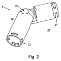
図2は、一実施形態に係るモジュール型ロボット用のエルボ継手モジュールの概略図である。エルボ継手モジュールは、中央シャフト20周りにて枢動するように構成される結合部8を備える。エルボ継手モジュールは、クイックリリース式雄型コネクタ21又はクイックリリース式雌型コネクタ22を用いるモジュールに結合される。クイックリリース式雄型コネクタ21は、追加的なモジュール内の補填クイックリリース式雌型コネクタ内に嵌合するよう構成される。追加的なモジュールは、クイックリリース式雄型コネクタの周縁部の突起が、それと同様の寸法を有し、クイックリリース式雌型コネクタの周縁部にて画定されるスロットと嵌合するときに固定される。本明細書において詳述するエルボ継手モジュールは、中央シャフト20周りにおける結合部8の回転領域は、±約90°である。しかしながら、異なるデザインにより、より大きいあるいは小さい領域の回転が可能となることは言うまでもない。最大回転角度よりも大きい回転を所望する場合、複数のエルボ継手モジュールをその端部から別の端部へと結合させることができる。
FIG. 2 is a schematic view of an elbow joint module for a modular robot according to an embodiment. The elbow coupling module includes a
図3は、図2のエルボ継手モジュールの内部機構の概略図である。結合部8は、駆動部26及び被動部27から形成される。駆動部26は、中央シャフト20を通して被動部27に結合される。モータ輪23を駆動部26に設け、そのモータ輪は、ギア輪を回転させるよう構成されたウォームギア24を駆動させる。ギア輪25は、被動部27に回転方向に固定される。モータによる操作によりウォームギア24を回転させるとき、ギア輪25が回転し、駆動部26に対するエルボ継手モジュール被動部27を屈曲させる。
FIG. 3 is a schematic view of an internal mechanism of the elbow joint module of FIG. The
本明細書に詳述するエルボ継手モジュールは、モータ及び被ギア機構を用いて回転させることができるが、代替的な実施形態も可能であることは言うまでもない。例えば、部材を、駆動部26及び被動部25の各側面の架設したケーブルを用いて回転させることもできる。
The elbow coupling module detailed herein can be rotated using a motor and geared mechanism, although it will be appreciated that alternative embodiments are possible. For example, the member can be rotated using cables installed on the side surfaces of the
本明細書に詳述するエルボ継手モジュールは、単一軸線周りのみにて回転させることができるが、代替的に、中央シャフト20を通じてユニバーサル継手モジュールを設けることで、被動部26の軸線方向に対する任意の軸線垂直方向にて回転させることも可能である。
The elbow coupling module detailed herein can be rotated only around a single axis, but alternatively by providing a universal coupling module through the
図4は、一実施形態に係るモジュール型ロボット用の回転モジュールの概略図である。回転モジュール7は、第1シャシ構成要素31及び第2シャシ構成要素32を備える。第1シャシ構成要素31は、第2シャシ構成要素32に対して、回転モジュール7の長手方向軸周りにて回転可能な構成を有する。ブッシュ33は、回転構成要素間の摩擦を低減させるために第1シャシ構成要素31と第2シャシ構成要素32との間の継手間に設けられる。クイックリリース式雄型コネクタ34のロック用の結節部は、第2シャシ構成要素32から、クイックリリース式雄型コネクタ34に結合された追加的なモジュール(図示せず)にトルクを伝達する構成を有する。
FIG. 4 is a schematic diagram of a rotation module for a modular robot according to an embodiment. The
モジュール型ロボットにおける回転モジュール7により、ロボット端部のツール又は回転モジュール7のロボットの下方部を、より多くの任意の方向に指向させることができる。
With the
図5は、一実施形態に係るモジュール型ロボット用のエルボ継手モジュールの概略図である。当該アセンブリにおいて、第1モジュール41は、第2回転モジュール42に結合され、これらのモジュール間にエルボ継手モジュールを設ける。ステップA〜Fとして図示されるように、第1モジュール41が時計回りに回転することにより、第2回転モジュールに沿って、エルボ継手モジュール43も回転する。モジュールの数が増加すると、第1回転モジュール41が要するトルクも増加、あるいは、支障を生じさせかねない。そのため、固定軸Gに対するエルボ継手モジュール43の角度を低減させることができる。第2回転モジュール42により、追加的なモジュール又はそれに取り付けるツールを、エルボ継手モジュール43に対して回転させ、それらの周辺環境に対するレベルを保持させることができる。
FIG. 5 is a schematic view of an elbow joint module for a modular robot according to an embodiment. In the assembly, the
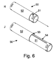
図6は、一実施形態に係るモジュール型ロボット用の伸張可能なシャシ・モジュールの概略図である。収縮位置H及び伸張位置Jにおける伸張可能なシャシ・モジュール50を示し、そのモジュールは、外側シャシ構成要素52及び内側シャシ構成要素51を備える。内側シャシ構成要素は、外側シャシ構成要素52の端部から伸縮可能に伸張するよう構成される。凹部スロット53は、外側シャシ構成要素52のケースの内面にて画定される。凹部スロット53は、内側シャシ構成要素51に設けられるタブ54を収容する構成を有する。凹部スロット53及びタブ54により、収縮位置H及び伸張位置Jの双方における、外側シャシ構成要素52と内側シャシ構成要素51との間の回転移動を確実なものとする。
FIG. 6 is a schematic diagram of an extensible chassis module for a modular robot according to one embodiment. An
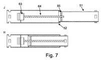
図7は、収縮位置H及び伸張位置Jの双方における図6の伸張可能なシャシ・モジュール用の内部機構の概略図である。外側シャシ構成要素52に固定されるモータ63は、リードスクリュ64に結合され、内側シャシ構成要素51に固定されるねじナット65にねじ込まれるリードスクリュ64に結合される。モータ63を操作するとき、リードスクリュ64はねじナット65にねじ込まれ、外側シャシ構成要素52に対して内側シャシ構成要素51を移動させる。
FIG. 7 is a schematic diagram of the internal mechanism for the expandable chassis module of FIG. 6 in both the retracted position H and the extended position
図8は、一実施形態に係る自由回転可能なホイールを備えるモジュール型ロボットの概略図である。このような特定の実施形態において、アームは複数の取り外し可能なモジュールから形成されるのではなく、床下空間のようなアクセスできない領域において、アームを用いてタスクを実行することができる多様な構成要素から形成される。側面図Tにおいて、伸張可能なシャシ・モジュール195を有するアームを設ける。伸張可能なシャシ・モジュールの内側伸張部の端部をハンドル194により終端させることで、アームを手動制御することができる。伸張可能なシャシ・モジュール195は、地面上でアームを移送し、粗い地面においてアームを簡易に操作するように配置されるホイールモジュール196を備える。ホイールモジュール196を超えて、伸張可能なシャシ・モジュール195を、ハンドル194を操作することで上傾及び下傾させることができるツール197に結合させる。上面図Uにおいて、アームは、ハンドル194をねじることにより左右に回転可能なツール197と共に示されている。伸張可能なシャシ195に対するツール197の角度により、ハンドルをねじり、ツールを回転させることにより生じる、スプレアークが決定する。この角度は、予め設定し、あるいは、例えばギア若しくはモータ、ケーブルなどのような第2アクチュエータにより制御することができる。伸張した構成Vに示すように、アームは伸張可能なシャシ・モジュールを方向198に伸ばすことにより伸張させることができる。
FIG. 8 is a schematic view of a modular robot including a freely rotatable wheel according to an embodiment. In such a specific embodiment, the arm is not formed from a plurality of removable modules, but various components that can perform tasks with the arm in inaccessible areas such as underfloor space. Formed from. In side view T, an arm having an
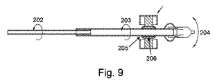
図9は、図8に示すモジュール型ロボット用の操作機構の概略図である。オペレータにより伸張可能なシャシ・モジュールの内側シャシ構成要素202に対して、回転移動が負荷されるとき、この移動は外側シャシ構成要素203を通じて伝達し、ツール204を枢動させる。ホイール207は、アームの重量を支持し、簡易な操作を可能とする。環部205及びブッシュ206により、ホイール207に対してアームを回転させることが可能となり、これにより、該ホイールを支持面に対して静止状態で保持することができる。
FIG. 9 is a schematic diagram of an operation mechanism for the modular robot shown in FIG. When rotational movement is applied to the
図10及び11は、一実施形態に係る電気機械的アームの側面図及び斜視図をそれぞれ示している。この電気機械的アーム300は、伸張可能なポール302並びに該ポール302の遠位端に設けられる3つのスプレーノズルを有するスプレーガン304を備える。伸張可能なポール302の遠位端に設けられるカメラ306は、スプレーガン304により何がスプレーされるのかを電気機械的アーム300のオペレータにフィードバックするような構成を有する。レンジファインダをカメラ306の隣に取り付けることができる。ハンドル308、表示スクリーン310形状のディスプレイ及びトリガ312は、伸張可能なポール302の遠位端と対向端にある近位端に設けることができる。電気機械的アーム300は、手動で配置できるような構成を有する。電気機械的アーム300は、建物の空間内で絶縁材料をスプレーするために用いることができる。当該実施形態において、伸張可能なポール302は、伸縮機構を用いて伸張させることができる。言うまでもなく、地面に沿って電気機械的アーム300全体をスライドさせることで、電気機械的アーム300の到達点を更に伸張させることできる。他の実施形態において、伸張可能なポール302の長さを伸張させるモジュールを付加することで、その長さを伸張させることができる。スプレーガン304は、ハンドル308のトリガ312を通じて、ソレノイド・スイッチ、空気バルブ又は他の手段を用いることで、遠隔操作することが可能となる。スプレーガン304上のスプレーノズルは、空間及び所望のスプレーパターン(典型的な状態にするために多数の既定位置を決めることができる)の物理的特性により、それらを填補するよう角度及び配置を調整することができる。伸張可能なポール302を伸張させる伸縮機構は、ハンドル308を転回させることで操作可能となる。伸張可能なポール302は、スプレーガン304に流体絶縁材料を供給するホース(図示せず)を収容する。図11に図示するように、ホース314は、ハンドル308に沿って電気機械的アーム300に挿入される。絶縁材料の種類により、ホースは、絶縁化又は加熱することができる。このようなシステムの利点として、直感的に理解しやすく、狭い空間においても遠隔操作により絶縁材料を塗布するために簡易にツールを操作することができる点が挙げられる。
10 and 11 show a side view and a perspective view, respectively, of an electromechanical arm according to one embodiment. The
いくつかの実施形態において、スクリーン及びトリガのいずれか又は双方は、アームからの遠隔位置における操作を可能とするよう設けられる。これにより、オペレータは、電気機械的アーム上に取り付けられたスクリーン画像を同時に見ることをせずとも、空間内にて電気機械的アーム300を配置することができる。本発明に係るシステムは、ディスプレイを目視し、アームを操縦するためにオペレータが用いる電話、タブレット、パソコンなどの既存の装置と通信を行うことができる。
In some embodiments, either or both of the screen and trigger are provided to allow operation at a remote location from the arm. This allows the operator to place the
図12及び図13は、一実施形態に係る電気機械的アームの側面図及び斜視図をそれぞれ示している。この電気機械的アーム400は、後述する相違点を除き、図10及び図11の電気機械的アーム300と実質的に同一である。電気機械的アーム400は、前方スタンド418及び後方スタンドにより支持されている。スタンド416及び418は、電気機械的アーム400を地面から離した状態で保持する。前方スタンド418及び後方スタンドは、環部機構を備えることで、伸張可能なポール402をスタンドに対して回転させ、スプレーガン404を転回させることできる。スタンド416及び418により、操作中に電気機械的アーム400を実質的に平坦な表面に配置することが可能となる。このような特定の実施形態において、スプレーガン404は、単一ノズルのみを備え、垂直面に対して既定の角度にて取り付けられる。第1位置と第2位置との間のハンドル408を回転させることで、ノズルの円弧状経路を走査することができる。このようにして、ハンドル408を回転させることで、絶縁材料を既定の角度範囲内における所望方向にスプレーすることができる。既定の角度を変更することで、スプレーガン404が通過する経路の円弧を変更することができる。アームが回転しても、カメラ406は静止状態を保つような構成を有する。代替的に、カメラをスプレーガン404に取り付けることで、ハンドル408の回転運動に伴ってカメラ406が移動する構成としてもよい。これにより、スプレーガンによりスプレーする方向にカメラを常に指向させることを確実なものとすることができる。しかしながら、このような構成は、使用者がスクリーン上で目視する際に混乱を生じさせかねない。いくつかの実施形態において、カメラは前方スタンド418に取り付けることができ、スプレーガン404とは独立して動かすことができる。
12 and 13 show a side view and a perspective view, respectively, of an electromechanical arm according to one embodiment. The
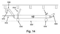
図14は、一実施形態に係る電気機械的アームの側面図である。この電気機械的アーム500は、後述する相違点を除き、図12及び図13の電気機械的アームと実質的に同一である。各スタンド516, 518は、電気機械的アーム500の操作面から離間させて支持する一対のホイールを備える。特に、ホイールにより電気機械的アーム500を簡易に操作面に沿って押すことができるため、より容易に電気機械的アーム500を操作することが可能となる。
FIG. 14 is a side view of an electromechanical arm according to one embodiment. The
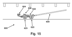
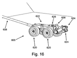
図15及び図16は、一実施形態に係る電気機械的アームの側面図及び斜視図をそれぞれ示している。この電気機械的アーム600は、後述する相違点を除き、図14の電気機械的アームと実質的に同一である。電気機械的アーム600は、電気機械的アームの本体を形成するシャシ622を備える。シャシ622は、その操作を簡易にするために4つのホイール620を備える。ホイール620は、典型的には、被動ホイールではなく、自由回転可能なホイールである。シャシ622の前方端は、そこに取り付けられたスプレーガン604を備える。スプレーガン604は、オフセット角度にて取り付けられ、シャシ622に対して回転移動可能であることにより、円弧状経路に沿ってスプレーガン604の目標点を移動させることができる。スプレーガン604は、電気信号からスプレーガン604の回転運動を生じさせるためにシャシ622内に取り付けられたギアボックス(図示せず)を通じて、モータに結合することができる。スプレーガンの角度は、駆動シャフト又はその他の手段に取り付けられたステップモータ又は回転速度計を制御することにより測定することができる。シャシ622の後方端は、電気機械的アーム600を操作するためにハンドル608に結合されている。シャシ622は、スプレーガン604の目標方向を観察するために取り付けられるカメラ606を更に備える。シャシ622は、空間を照射してその3次元マッピングを生成するために取り付けられた高原及びレンジファインダ626をそれぞれ備える。一対のレーザー624をスプレーガン604の下側面に取り付けることで、スプレーガン604の目標点を示す十字状のレーザ(図示せず)を、スプレーガン604によりスプレーすべき表面に投影することができる。代替的に、レンジファインダは、3次元画像を生成する領域をスキャン可能なレーザレンジファインダ(ライダ)又は同様の装置を備えていてもよい。レーザーガンの角度及びスプレーを塗布する表面に対する相対位置を知ることができるため、目標点は、計算可能であり、オペレータが目視する画像上でデジタル的にオーバーレイすることができる。ノズルを通じて、カメラ606及びレンジファインダ626の周囲に圧空を供給することで、空気カーテン(図示せず)により、レンジファインダ及びカメラを絶縁材料から保護することができる。カメラ606により観察可能なように目標点を構成することで、電気機械的アーム600のオペレータが目標点を表示することが可能となる。電気機械的アーム600の到達範囲は、長さの異なるハンドルに付け替えることで、あるいは、付加的なハンドル部材を付加することで変更することができる。
15 and 16 show a side view and a perspective view, respectively, of an electromechanical arm according to one embodiment. The
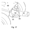
図17は、図15及び図16の電気機械的アームのピボット継手の拡大概略図である。電気機械的アーム600のシャシ622は、ユニバーサル継手628を介して結合される。ユニバーサル継手628により、電気機械的アーム600を一定方向に操作することが可能となる。ユニバーサル継手628は、ハンドル608に結合するハンドル部630、及びシャシ622に結合するアングル部632を備える。アングル部632は、ユニバーサル継手をシャシ622に結合させるアングル孔634を備える。ハンドル608を回転させると、ねじれ運動が、シャシ622、続いてスプレーガン604を転回させる。これにより、オペレータは、スプレーガン604が目標点を指向した状態で、ハンドル608により電気機械的アーム600の方向を変更させることができる。特に、結合ピンをシャシ622に対して所定角度でアングル孔634に取り付けることで、ハンドル608の回転によりシャシ622を平行に転回させることを確実なものとする。
FIG. 17 is an enlarged schematic view of the pivot joint of the electromechanical arm of FIGS. 15 and 16. The
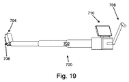
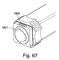
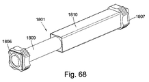
図18及び図19は、本発明の一実施形態に係る電気機械的アームの側面図及び斜視図をそれぞれ示している。この電気機械的アーム700は、後述する相違点を除き、図10及び図11の電気機械的アームと実質的に同一である。カメラ及びレンジファインダ706は、スプレーガン704の下方に取り付けられる。このように取り付ける構成により、例えば凝固する絶縁材料など、電気機械的アーム700上に落下するあらゆる異物からカメラ及びレンジファインダ706を保護することができる。この特定の実施形態において、ハンドルを、電気機械的アーム700の伸張及びスプレーガン704の回転を制御するために用いることができる。カメラ及びレンジファインダは、スプレーガンに取り付けられることで、目標点を追従するよう回転する。レンジファインダにより、塗布する前後の材料の測定を行うことができるため、補填する厚さを計算することができる。レンジファインダは、スプレーガンの回転時に領域内に3次元スキャンを生成するように取り付けられた2次元平面をスキャンするライダを備えていてもよい。ハンドル708を角度90°の位置にリフトすることで、アームの伸張を調整が可能となる。ハンドル708を時計回り又は反時計回りに回すことで、スプレーノズル704のも目標方向を調整することなく、伸縮可能なポール702の長さを調整することができる。更に、伸張可能なポール702の軸線に平行な方向に対してハンドルを90°から0°(典型的には、約45°)のアングル位置に移動させて戻すことで、伸張可能なポール702の伸張を制御することなく、スプレーガンの回転運動を制御するよう個別の機構を係合させることができる。スプレーガン704の底部に取り付けられたカメラ706は、表示スクリーン710を通じてオペレータに視覚的なフィードバックを提供する。スプレーガン704は、水平面に対して、約70°の角度で取り付けられる。
18 and 19 show a side view and a perspective view, respectively, of an electromechanical arm according to an embodiment of the present invention. This
図20は、一実施形態に係る電気機械的アームの側面図である。この電気機械的アーム800は、後述する相違点を除き、図18及び図19の電気機械的アームと実質的に同一である。伸張可能なポール802は、図12及び図13において実質的に上述した機能と同様に前方スタンド818及び後方スタンド816により支持される。スプレーガン804は、水平面に対して、約45°の角度で取り付けられる。
FIG. 20 is a side view of an electromechanical arm according to one embodiment. The
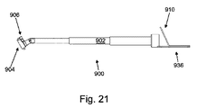
図21及び図22は、一実施形態に係る電気機械的アームの側面図及び斜視図をそれぞれ示している。この電気機械的アーム900は、後述する相違点を除き、図18及び図19の電気機械的アームと実質的に同一である。電気機械的アーム900は、スプレーガン904を多様な方向に指向可能とするリスト及びエルボ継手940を、伸張可能なポール902とスプレーガン904との間に備える。リスト及びエルボ継手940については、図39に関する説明においてより詳細に後述する。電気機械的アーム900は、カメラ906からの画像を表示するスクリーンを有するパソコン936形状のマイクロ・コントローラを更に備える。従って、パソコンは、スプレーガン904の位置決定を行うオペレータに視覚的なフィードバックを提供することができる。電気機械的アーム900は、パソコン936に接続されたゲームパッド938形状のコントローラを用いて制御することができる。電気機械的アーム900の位置センサは、パソコン936にデータを提供する。
21 and 22 show a side view and a perspective view, respectively, of an electromechanical arm according to one embodiment. The
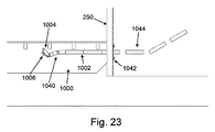
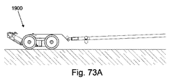
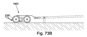
図23は、本発明の一実施形態に係る電気機械的アームの側面図である。この電気機械的アーム1000は、後述する相違点を除き、図21及び図22の電気機械的アームと実質的に同一である。伸張可能なポール1002は、複数のインターロック及びモジュール部から形成される。付加的なアーム部1044を電気機械的アーム1000に付加することで長さを伸張することができる。必要に応じて、電気機械的アーム1000に他の部材を挿入できることは言うまでもない。例えば、伸張可能なポール1002の端部に設けられ、スプレーガン1004に結合されるリスト及びエルボ継手1040を挿入することができる。いくつかの実施形態においては、短いポール部を複数結合させたポール部ではなく、適切な長さを有する単一ポール部のみを用いる。電気機械的アーム1000は、外壁250内で画定されるホールに固定される壁取付部1042から床下空間に伸張する。この壁取付部は、図47に関する説明にて更に詳述する。
FIG. 23 is a side view of an electromechanical arm according to an embodiment of the present invention. The
図24及び図25は、一実施形態に係る電気機械的アームの側面図及び斜視図をそれぞれ示している。この電気機械的アーム1100は、後述する相違点を除き、図23の電気機械的アームと実質的に同一である。伸張可能なポールの代わりに、電気機械的アーム1100は、ピボット1152の端部に設けられる環部1150内でスライドする構成を有するスライド・ポール1146を備える。電気機械的アームが床取付部1154を通じて床260にて画定されるホールに取り付け可能となるよう、ピボットは床取付部1154に結合される。床取付部1154は、図46に関する説明にて更に詳述する。床取付部1154を通じて床160に作用するモーメントを確実に最小限とするため、スプレーノズル1104の対向端にあるスライド・ポール1146の端部に平衡錘1148を設ける。平衡錘1148により、電気機械的アーム1100を確実に簡易に移動させることができる。平衡錘1148の重量は、例えば水などのバラスを充填することで増減させることができる。いくつかの実施形態において、平衡錘1148は、床取付部1154を通じて床260に作用するモーメントの均衡を保つため、スライド・ポール1146上で移動するような構成を有する。スライド・アーム機構は、スプレーノズル1104を前方及び後方に移動させ、スライド・ポール1146を回転させるために手動操作又はロボット制御することが可能である。電気機械的アーム1100は、床260のレベルを超えて伸張する代替的なハンドル(図示せず)を用いることで、直接制御することができる。代替的に、電気機械的アーム1100は、モータを通してスクリーンを用い、アームにより遠隔操作するコントローラを用いて、遠隔操作することができる。スライド・ポール1146は、空間内のスプレーガン1104の到達を伸張するよう環部1150を通じてスライドすることができる。図46に関する説明にて更に詳述するように、床取付部1154を床260の開口部に打ち込むことで、電気機械的アーム1100の固定された取付点を設けることができる。
24 and 25 show a side view and a perspective view, respectively, of an electromechanical arm according to one embodiment. The
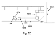
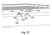
図26及び図27は、一実施形態に係る電気機械的アームの側面図及び斜視図をそれぞれ示している。この電気機械的アーム1200は、後述する相違点を除き、図24及び図25の電気機械的アームと実質的に同一である。電気機械的アーム1200は、床で画定されるホールに取り付けられる代わりに、壁取付部1242を用いて取り付けることができる。環部1250によりスライド・ポール1246を導入及び導出させることにより、電気機械的アーム1200の到達を伸張させることが可能となる。しかしながら、電気機械的アーム1200は、壁取付部1242を用いて取り付けられるため、スライド・ポール1246は、環部1250を通じてわずかにスライドするのみである。ピボット1252により電気機械的アーム1200をピボット1252周りに回転させることができ、これにより、スプレーガン1204を異なる位置の領域にアクセス可能とすることができる。電気機械的アーム1200を空間内に更に伸張させるために、付加的なアーム部(図示せず)を、図23にて上述した方法と同様に、壁取付部1242に付加することができる。電気機械的アーム1200は、通気口の入口システムと用いることができ、建物の壁250からピボットへの到達は適切に調整することができる。特に、このような設計は、通気口の出入口が垂直配列から外れているペリスコープベントに適している。
26 and 27 show a side view and a perspective view, respectively, of an electromechanical arm according to one embodiment. The
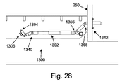
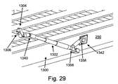
図28及び図29は、一実施形態に係る電気機械的アームの側面図及び斜視図をそれぞれ示している。この電気機械的アーム1300は、後述する相違点を除き、図23の電気機械的アームと実質的に同一である。上方エルボ部1358は、壁取付部1342と伸張可能なポール1302との間に設けることができる。下方エルボ部1356は、上方エルボ部1358と伸張可能なポール1302との間に設けることができる。このような方法により、空間内の伸張可能なポール1302の高さを多様なものとしながら、伸張可能なポール1302を空間の底面に対して平行に伸張させ続けることができる。この特定の構成は、調整可能であり、多様な異なる開口部の種類に適用することができる。
28 and 29 show a side view and a perspective view, respectively, of an electromechanical arm according to one embodiment. The
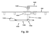
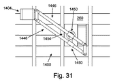
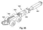
図30及び図31は、一実施形態に係る電気機械的アームの側面図及び底面図をそれぞれ示している。この電気機械的アーム1400は、後述する相違点を除き、図24及び図25の電気機械的アームと実質的に同一である。図41に関する説明にて更に詳述するように、電気機械的アーム1400は電気的に制御されるスプレーノズルを備え、該スプレーノズルは、2つの環部1450を通じてスライドするように構成された2つのスライド・ポール1446から形成される4つの棒リンク機構に結合されている。2つの環部1450は、床取付部1454に固定された継手リンクにより結合されている。環部1450の1つは、ピボットは舵柄1462に結合されたピボット1452に結合されている。舵柄を回転させることで、円弧状経路内でスプレーガン1404を移動させながら、スプレーガン1404を同一の方向に確実に指向させ続けることができる。4つの棒リンク機構は、舵柄1462の回転運動をスプレーガン1404の円弧状運動へと変換させ、スプレーガン1404により、円弧状運動を通じて床260に対して同一の方向を指向させ続けることができる。制御ホイール1460は、取付けのために床上に設けられ、ギアリングを用いて4つの棒リンク機構に結合される。特に、制御ホイール1460を回転させることで、環部1450を通じてスライド・ポール1446をスライドさせ、スプレーガン1404の到達を伸張又は収縮させることで、スプレーガン1404の伸張を制御することができる。この特定の実施形態において、舵柄1462を、電気機械的アーム1400の全体の回転運動又は休止位置における該アームの残余部に係合するよう持ち上げることで、4つの棒リンク機構によりスプレーガン1404を実質的に側方に移動させることができる。このような機構の利点として、スプレー装置を、運動全体を通じて平行に保持できることが挙げられる。
30 and 31 show a side view and a bottom view, respectively, of an electromechanical arm according to one embodiment. The
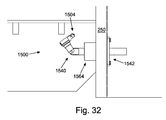
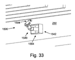
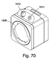
図32及び図33は、一実施形態に係る電気機械的アームの側面図及び斜視図をそれぞれ示している。電気機械的アーム1500は、後述する相違点を除き、図23の電気機械的アームと実質的に同一である。電気機械的アーム1500は、鋳型1564を備え、該鋳型により電気機械的アーム1500を壁250から除去するときに、壁250内で画定される通気口の周辺領域を均整よく仕上げることができる。スプレーガン1504は、電気機械的アーム1500の軸線周りにて回転させることができ、スプレーガン1504の正確な配置を可能とするエルボ及びリスト継手1540を備える。床下に絶縁材料を塗布した後であっても床下空間に通気性を保つために開放開口部を備える必要がある。
32 and 33 show a side view and a perspective view, respectively, of an electromechanical arm according to one embodiment. The
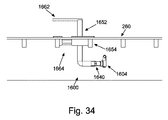
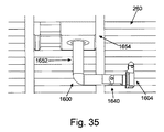
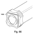
図34及び図35は、一実施形態に係る電気機械的アームの側面図及び斜視図をそれぞれ示している。電気機械的アーム1600は、後述する相違点を除き、図32及び図33の電気機械的アームと実質的に同一である。特定の実施形態において、電気機械的アーム1600は、床板仕上げツールとして参照してもよい。電気機械的アーム1600は、手動駆動源付きツールであって、スプレーガン1604を、床260の開口部及び鋳型1664周りにて回転させる。電気機械的アーム1600は、舵柄1662を通して回転されるピボット1652を備える床取付部1664を通じて伸張する。これにより、一片のうね状の絶縁パネルにより充填され、後の工程において、より簡易なアクセスを可能とするために除去される、均整のとれたアクセスハッチを形成することができる。
34 and 35 show a side view and a perspective view, respectively, of an electromechanical arm according to one embodiment. The
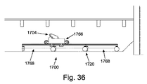
図36及び図37は、一実施形態に係る電気機械的アームの側面図及び斜視図をそれぞれ示している。電気機械的アーム1700は、図41に関する説明にて更に詳述するスプレーガン1704を備える。ガン・キャリッジ1766に取り付けられるスプレーガン1704は、ホイールを備え、複数のレール部1768を有するモジュール・トラックシステムに沿って移動する構成を有する。複数のレール部1768は、簡易な組み立て及びトラックの操作を可能とする複数のホイール1720を備える。ホイールを備えるガン・キャリッジ1766は、トラック上を移動し、スプレーガン1704により広範囲に亘りスプレー可能とするような双軸運動システムを備える。
36 and 37 show a side view and a perspective view, respectively, of an electromechanical arm according to one embodiment. The
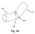
図38は、一実施形態に係る電気機械的アーム用のエルボ継手の概略図である。エルボ継手210は、第1部材211及び結合軸213を通じて第1部材211に回転可能に結合される第2部材212を備える。第1部材211は、結合軸213周りの回転により、第2部材212に対して回転可能に配置される。エルボ継手210は、動力エルボ継手であり、アームを単軸で簡易に操作可能とする。これにより、電気機械的アームは、角部、寝台壁にも到達することができ、床下空間の障害物を避けることができる。モータ(図示せず)に取り付けられるウォーム・ギアボックスは、エルボ継手210の移動を操作し、正確な配置を可能とする。エルボ継手210は、モジュールであり、多様なアームの構成を可能とするよう、更なるモジュールに結合させることができる。
FIG. 38 is a schematic view of an elbow joint for an electromechanical arm according to one embodiment. The elbow joint 210 includes a
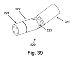
図39は、一実施形態に係る電気機械的アーム用のエルボ継手及びリスト継手の組み合わせの概略図である。エルボのエルボ継手部及びリスト継手220は、図38の電気機械的アームと実質的に同一である。回転部材224、あるいは、リスト継手として知られる部材は、結合軸223を通じて第1部材221に結合される端部の対向端である、第2部材222の端部に設けられる。その結果、アームの当該部分は、双軸運動を有する。図38に示すように、アーム全体を上下運動させることができる動力ヒンジを備える。アームは、継手220の第1部材221及び第2部材222に対する継手220の回転部材224を回転させることができるリスト継手部分も備える。リスト部の端部は、あらゆるスプレーガンを取り付け可能とする取付部を備える。遊星ギアボックス及びモータ(図示せず)は、リスト及びウォーム・ギアボックスの回転運動を制御し、モータ(図示せず)は、エルボ継手の運動を制御する。
FIG. 39 is a schematic view of a combination of an elbow joint and a wrist joint for an electromechanical arm according to one embodiment. The elbow joint and
図40は、一実施形態に係る電気機械的アーム用の単軸スプレーガンを2つの側面から示す概略図である。スプレーガン230は、単軸スプレーガン形状を有し、スプレーガン230から、例えば絶縁材料などの処理剤をスプレーするために有用であるノズル231を備える。スプレーガン230は、スプレーガン230の目標点を捉えるカメラ232を更に備える。カメラは、スプレーガン230から離れた位置に配置され、スプレーガン230により処理剤をスプレーする領域をオペレータが目視することを可能とする表示スクリーン(図示せず)に結合可能である。スプレーガン230は、この特定の実施形態において、約70°の角度で取り付けられるアングル平面233を更に備える。単軸スプレーガンの運動は、リスト継手234を用いて単軸周りにノズルを回転させることで生じさせることができる。回転軸の端部に取り付けられるアングル平面233は、ノズル231がその内部を通過する円弧状スプレー経路を設置する。異なる角度のアングル平面を、空間の高さ及び所望のスプレー方法に応じて取り付けることができる。
FIG. 40 is a schematic view showing a single-axis spray gun for an electromechanical arm according to an embodiment from two sides. The
図41は、一実施形態に係る電気機械的アーム用の2軸移動スプレーガンの概略図である。スプレーガン240は、双軸スプレーガン形状を有し、電気機械的アームの更なるモジュールに結合可能なハウジング245内において可動である可動平面上に設けられるノズル241を備える。スプレーガン240は、可動平面の前方に配置される水平軸246周りを回転する垂直平面上にて移動させることができる。スプレーガン240は、可動平面の後方からその前方に対して、可動平面の中央位置から約2/3の位置に配置される横軸247周りにて回転する水平面上にて移動させることができる。これによりスプレーガン240は、スプレーをしながら、広域をカバーすることができる。このようなスプレーシステムにより、複雑なパターンを達成することができ、広域を迅速かつ完全にカバーすることを確実なものとする。典型的には、水平軸をスプレーガンの前方端に隣接するように配置することにより、スプレーガンを、平坦な構成を有するアームの前方におけるあらゆる障害物を乗り越えるのに十分な高さに配置しながら、上方角においてスプレーガンが上方に突出しないことを確実なものとする。
FIG. 41 is a schematic diagram of a two-axis moving spray gun for an electromechanical arm according to one embodiment. The
図42は、一実施形態に係る、水平方向にて離間するよう配置された3つのノズルを備える複数のスプレーノズルモジュールを2方向から示す概略図である。図示するように、それぞれの角度で3つのスプレーガンを配置することで、使用者は、短時間で非常に広範囲に亘りカバーすることができる。 FIG. 42 is a schematic view illustrating a plurality of spray nozzle modules including three nozzles arranged to be spaced apart in the horizontal direction according to an embodiment from two directions. As shown in the figure, by arranging three spray guns at respective angles, the user can cover a very wide area in a short time.
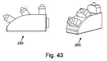
図43は、更なる実施形態に係る、垂直方向にて離間するよう配置された3つのノズルを備える複数のスプレーノズルモジュールを2方向から示す概略図である。水平面上に多様な角度を付けたスプレーガンは、単一スプレーにより床下の梁間の領域をカバーするために設計された。言うまでもなく、図42及び図43は、3つの個別のスプレーガンを図示しているが、3つ以上またはそれ以下のスプレーガンを備えていてもよい。更に、いくつかの実施形態において、単一スプレーガンは、必要に応じて、複数のスプレーノズルを備えることができる。 FIG. 43 is a schematic diagram showing a plurality of spray nozzle modules from two directions with three nozzles arranged to be vertically spaced according to a further embodiment. Spray guns with various angles on the horizontal plane were designed to cover the area between the beams under the floor with a single spray. Of course, FIGS. 42 and 43 illustrate three individual spray guns, but may include more or less than three spray guns. Further, in some embodiments, a single spray gun can include multiple spray nozzles as needed.
図44は、一実施形態に係る電気機械的アーム用のインラインカメラを備えるスプレーガンの概略図である。スプレーガン231及びカメラ232は、使用者が、スプレーをしている場所を簡易に目視できるような構成で取り付けることができる。スプレーガン231は、取付面238に対して約70°の角度で取り付けることができ、典型的には、スプレーガンをリスト継手又は他の回転可能部材上に取り付けるときに、床の梁間の全領域を使用者によりスプレー可能とする角度にて取り付ける。
FIG. 44 is a schematic view of a spray gun with an inline camera for an electromechanical arm according to one embodiment. The
図45は、一実施形態に係る電気機械的アーム用のスプリンクラー型スプレーガンを2方向から示す概略図である。スプリンクラー型スプレーガン280は、複数のノズル231を備える。特定の実施形態において、スプリンクラー型スプレーガン280は、直線上に配列され、実質的に同一方向に処理剤をスプレーするよう構成される5つのノズルを備える。複数のスプレーノズルにより、カバー領域を最大化させることができる。ノズルが突出するスプレーガンのバレルは、該バレルを回転可能とするモータ及びギアボックス(図示せず)に取り付けられる。モータのエンコーダにより、スプリンクラー型システムにおける正確な位置に関するフィードバックを生成することができる。
FIG. 45 is a schematic view showing a sprinkler type spray gun for an electromechanical arm according to an embodiment from two directions. The sprinkler
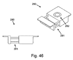
図46は、一実施形態に係る電気機械的アーム用の床板の取付を2方向から示す概略図である。床取付部280として参照する床板の取付装置は、床の梁間にてその取付部を保持する構成を有し、梁の側面に2つの部分を押し込むスプリング281を用いる。床取付部280は、床板間に収容され、梁間にてその取付部を保持するように伸張する。ホールは、床取付部280を貫通し、電気機械的アームの取付部を構成する。このような取付部により、アームを支持しながら、アームの自由回転運動を可能とする。
FIG. 46 is a schematic view showing attachment of a floor plate for an electromechanical arm according to one embodiment from two directions. The floor plate mounting apparatus referred to as the
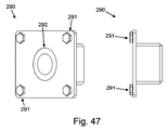
図47は、電気機械的アーム用の通気口の取付を2方向から示す概略図である。通気口取付部として参照する、壁取付部290は、ダブル中空レンガにより生じる空間に収容されるように設計される。取付部を、ボルト291を用いて壁にねじ込むことで、確実に取り付けることができる。床取付部280に関して、壁取付部290は、その内部で画定され、電気機械的アーム280を取り付けるためのホール292を備える。取付部によりアームを支持することで、アームが空間から出入りすること、及びその回転を可能とする。
FIG. 47 is a schematic view showing attachment of a vent for an electromechanical arm from two directions. The
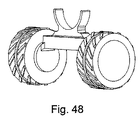
図48は、一実施形態に係る電気機械的アーム用のホイール・アームホルダの概略図である。ホイール・アームホルダは、空間内での移動及び操作中に、アームを支持するようアームの伸張部材に簡易に取り付けることができる。 FIG. 48 is a schematic view of a wheel arm holder for an electromechanical arm according to one embodiment. The wheel arm holder can be easily attached to the arm extension member to support the arm during movement and manipulation in space.
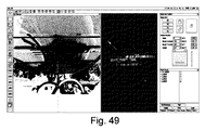
図49〜図51は、電気機械的アームのオペレータが同アームに取り付けたスプレーガンを制御するために使用する、本発明の一実施形態に係るユーザ・インターフェイスの概略図である。 49-51 are schematic views of a user interface according to one embodiment of the present invention used by an electromechanical arm operator to control a spray gun attached to the arm.
図49は、オーバーレイされたマッピング及びスキャニングからの情報を記録した搭載カメラからの配信画像を図示している。オペレータは、矢印によりスプレーガンが目標方向を目視することができ、例えば、ゲームパッド・コントローラにより、その移動を直接制御することができる。オペレータは、スプレーする領域を選択することもでき、電気機械的アームは、その領域をスプレーするために必要な移動を計算する。このような場合、ストロークは、カメラの配信画像上のスプレーすべき領域にてオーバーレイされる水平なラインとして示される。図49〜図51に示すように、カメラの処理側面を目視すると共に、使用者は、電気機械的アーム全体の配置を異なる側面から見ること、及び処理すべき空間内におけるスプレーガンの方向を選択することができる。 FIG. 49 illustrates a delivery image from an onboard camera that has recorded information from overlaid mapping and scanning. The operator can visually observe the target direction of the spray gun by the arrow, and can directly control the movement of the spray gun by, for example, a game pad controller. The operator can also select the area to spray and the electromechanical arm calculates the movement required to spray that area. In such a case, the stroke is shown as a horizontal line overlaid on the area to be sprayed on the camera distribution image. While viewing the processing side of the camera, as shown in FIGS. 49-51, the user views the entire electromechanical arm arrangement from a different side and selects the direction of the spray gun in the space to be processed can do.
言うまでもなく、いくつかの実施形態において、電気機械的アームは、空間内の電気機械的アームの位置情報を提供する傾斜センサ形状の配置センサを備える。このようにして、図49〜図51に示す制御インターフェイスにより、電気機械的アームのスプレーガンの位置情報を提供することで、空間及び、スプレーガンの目標方向に加え、特に空間内の電気機械的アームの位置のマッピングを生成することができる。 Of course, in some embodiments, the electromechanical arm comprises a position sensor in the form of a tilt sensor that provides positional information of the electromechanical arm in space. In this manner, by providing the position information of the spray gun of the electromechanical arm by the control interface shown in FIGS. 49 to 51, in addition to the space and the target direction of the spray gun, in particular, the electromechanical arm in the space. A mapping of arm positions can be generated.
カメラは、視覚画像又はサーマル画像であってもよい。レンジ・ファインディングシステムは、超音波、レーザースキャナ(例えば、HokuyoURG-04LX)又は赤外線(例えば、Creative Senz3D)であってもよい。センサ・プラットフォームは、完全な3次元画像を取得するよう回転させ、パンさせることができる。スプレーガンを1つ又は2つの軸線上の動力ガン・プラットフォームに取り付けることで、オペレータは、この材料の塗布を遠隔操作することができ、これはゲームパッド・コントローラにより直接行い、又は所定領域をカバーするために所望のスプレーパターンを装置により計算することで実行することができる。 The camera may be a visual image or a thermal image. The range finding system may be ultrasound, laser scanner (eg HokuyoURG-04LX) or infrared (eg Creative Senz3D). The sensor platform can be rotated and panned to obtain a complete 3D image. By attaching the spray gun to the power gun platform on one or two axes, the operator can remotely control the application of this material, either directly by the gamepad controller or covering a predetermined area In order to do this, the desired spray pattern can be calculated by the device.
材料を塗布するための制御システムは、レンジファインダからの情報を取得し、9自由度の運動/傾斜センサによりスプレーすべき表面に対する電気機械的アームの位置を計算することができる。オペレータによる手動のスプレーを補助するために、この情報を配信画像上に示すことで、スプレーガンの目標点を示すことができる。あるいは、オペレータがマッピング又は配信画像の領域を選択することで、ロボット車両によりスプレーすべき領域を自動的に計算させることができる。 A control system for applying the material can obtain information from the range finder and calculate the position of the electromechanical arm relative to the surface to be sprayed by a nine degree of freedom motion / tilt sensor. In order to assist the manual spraying by the operator, this information can be displayed on the distribution image to indicate the target point of the spray gun. Alternatively, the area to be sprayed by the robot vehicle can be automatically calculated by the operator selecting the area of the mapping or distribution image.
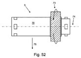
図52は、本発明の一実施形態に係るモジュール型ロボット用の側方駆動モジュールの概略図である。側方駆動モジュール5は、シャシ構成要素70及びその外部に設けられる駆動ホイールを備える。駆動ホイール73は、シャシ構成要素70の長手方向軸線74周りに回転する構成を有することで、側方方向に少なくとも側方駆動モジュールを駆動させる垂直運動を生成する。いくつかの実施形態において、駆動ホイール73は、シャシ構成要素の長手方向軸線74方向における自由運動を可能とするが、側方の静止摩擦を生じさせる、全方位ホイールであってもよい。
FIG. 52 is a schematic diagram of a side drive module for a modular robot according to an embodiment of the present invention. The
本明細書において「側方」とは、一般的な意味である、横方向、特に長手方向に対して垂直である方向を指す。 As used herein, “lateral” refers to the general meaning, the direction that is perpendicular to the lateral direction, particularly the longitudinal direction.
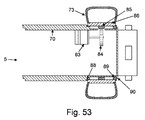
図53は、図52の横方向ドライブ・モジュール用の内部機構の概略図であり、側方駆動モジュール5を通じて部位を示している。モータ83は、側方駆動モジュール5のシャシ構成要素70内に固定されている。モータ83は、ピニオンギア84を駆動させ、ホイールハブ86に取り付けられた外輪85を駆動させる構成を有する。ブッシュ又はベアリング88, 89は、シャシ構成要素70に対して駆動ホイール73を回転可能とさせるために、シャシ構成要素70とホイールハブ86との間に設けられる。ブッシュ又はベアリング88, 89は、保持輪90により所定位置に配置される。
FIG. 53 is a schematic diagram of the internal mechanism for the lateral drive module of FIG. 52, showing the site through the
図54は、本発明の一実施形態に係る、可動構成要素の概略図である。可動構成要素は、アンカーモジュール4であって、アンカーモジュール4の表面から屈出するような構成を有する4つの収縮グリッパ92を備える。アンカーモジュール4は、平坦な構成で図示されており、各グリッパ92は、アンカーモジュール4の表面に対して平坦に圧縮されている。このような構成とすることで、アンカーモジュール4を障害なしに遠隔操作し、周辺環境において移動させることが可能となる。図55においてより完全に詳述するように、グリッパは、アンカーモジュール4の表面から屈出するような構成で展開するとき、モジュールを所定位置に保持することができる。
FIG. 54 is a schematic diagram of a movable component, according to one embodiment of the present invention. The movable component is an anchor module 4 comprising four
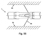
図55は、第1モードにおける図54の可動構成要素の概略図である。遠隔操作されたアーム1が、第1表面93と第2表面94との間の周辺環境にて操作されるとき、展開グリッパ95は、アンカーモジュール4を所定位置に保持するように展開する。2つの表面は、側壁、パイプ又は床の壁及び空間の仕切りであってもよい。代替的に、従来のアンカーにおいて、グリッパを単に地面に埋設することもできる。
FIG. 55 is a schematic diagram of the movable component of FIG. 54 in the first mode. When the remotely operated
図56は、図54及び図55の可動構成要素用の内部機構の概略図であり、アンカーモジュール4を通じて部位を示している。この内部機構の第1位置に示される収縮グリッパ92と、第2位置に示される展開グリッパ95を示す。モータ101をアンカーモジュール内に設ける。モータ101は、リードスクリュ102を駆動させる。機構の第1位置において、リードスクリュが回転方向に固定化されナット104と係合することで、リードスクリュをモータ101に向けて、軸線に沿って下方に移動させることができる。スクリュの運動は、ピン109を通じてリンケージ110に伝達され、収縮グリッパ92を収縮位置から展開位置に移動させる。展開グリッパ95に示すように、ナット104と同一の構成要素を有するナット103が、モータ104に近い位置に配置される結果、展開グリッパ95は展開位置に配置される。
FIG. 56 is a schematic view of the internal mechanism for the movable component of FIGS. 54 and 55, showing the site through the anchor module 4. A
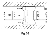
図57は、一実施形態に係る、モジュール型ロボット用の可動構成要素としての膨張可能リング概略図である。アンカーモジュール111は、その一部の外部の周辺に設けられる膨張可能リング112を備える。膨張可能リング112は、下側表面113の障害物との接触に耐えうる十分な剛性を備える軟質材料から形成される。圧縮位置において、膨張可能リング112は、下側表面にて休止し、側方方向におけるアンカーモジュールの移動を防止しない。
FIG. 57 is a schematic diagram of an inflatable ring as a movable component for a modular robot, according to one embodiment. The
図58は、図57の可動構成要素の、膨張状態にあるリング112の概略図である。膨張可能リング112は、下側表面113及び上側表面124に接触する。膨張可能リング112と下側表面113、膨張可能リング112と上側表面124との間の接触は、モジュール型ロボット内の他のモジュールが他の操作を行っている間において、遠隔被操作アームを所定位置に保持し、その移動を防止するアンカーとして作用する。この特定の実施形態において、アンカーモジュール111は、アンカーモジュール111と膨張可能リング112との間に設けられるブッシュを備え、軸線方向125にて膨張状態にあるリングの中心を通じて、遠隔被操作アームをスライドさせるよう低摩擦スライド継手を設ける構成を有する。これにより、典型的には、地面に埋設する遠隔被操作アームと比べて摩擦を低減することができる。また、地面に埋設することにより潜在的なダメージのリスクから、アームのモジュールの精密な構成要素を保護することができる。
58 is a schematic view of the
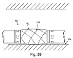
図59は、一実施形態に係る、モジュール型ロボット用の可動構成要素としての半硬性膨張可能リングの概略図である。アンカーモジュール131は、軟質材料及びワイヤーメッシュ133から形成される半硬性膨張可能リング132を備える。半硬性膨張可能リング132は、圧縮され、下側表面134にて休止している構成を図示している。いくつかの実施形態において、軟質材料は、図57及び図58に関して上述した膨張可能リングと同一の材料を用いることができる。
FIG. 59 is a schematic diagram of a semi-rigid inflatable ring as a movable component for a modular robot, according to one embodiment.
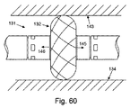
図60は、図59の可動構成要素の、膨張状態にある半硬性リング概略図である。アンカーモジュール131は、膨張状態で配置される半硬性リング132が設けられる。膨張されると、半硬性リング131は、下側表面134と上側表面143との間のアンカーモジュールを保持する。図60は、半硬性リング132の最大径を図示している。代替的な構成において、リング132の側面を方向145及び方向146に沿って押し広げ、リング132の2つの側面間の間隔を増加させることで、リングの直径を縮小させることできる。
FIG. 60 is a schematic diagram of the semi-rigid ring in an expanded state of the movable component of FIG. The
同様に、より長い半硬性リングと組み合わせて用いるより長いアンカーモジュールは、更に間隔を広げた2つの側面間をアンカー可能なアンカーモジュールとして作用することは言うまでない。 Similarly, it goes without saying that a longer anchor module used in combination with a longer semi-rigid ring acts as an anchor module capable of anchoring between two more spaced sides.
図61は、一実施形態に係る、モジュール型ロボット用の可動構成要素及び膨張可能シャシの組み合わせの操作態様を示す概略図である。伸張可能なシャシ・モジュール158は、上側表面160と下側表面170との間の空間に設けられるアンカーモジュール159に結合される。アンカーモジュール及び伸張可能なシャシ・モジュールの操作を制御することにより、遠隔被操作アームを前方に推進させることができる。アンカーモジュールが上側表面160又は下側表面161と非接触状態にあるとき、アセンブリを支持する更なるモジュールとの結合により、アセンブリを上側表面160と下側表面161との間の所定位置に保持することができる。
FIG. 61 is a schematic diagram illustrating an operation mode of a combination of a movable component for a modular robot and an inflatable chassis according to an embodiment. The
第1工程Kにおいて、伸張可能なシャシ・モジュール158及びアンカーモジュール159
は収縮状態にある。第2工程Lにおいて、伸張可能なシャシ・モジュール158を伸張させることで、伸張可能なシャシ・モジュール158及びアンカーモジュール159を上側表面160と下側表面161との間の空間に移動させる。工程Mにおいて、アンカーモジュール159のグリッパ162を展開させ、上側表面160及び下側表面161と係合させ、アンカーモジュールを所定位置に保持する。工程Nにおいて、伸張可能なシャシ・モジュール158が収縮することで、空間に沿ってアセンブリの後方を移動させる。工程Oにおいて、グリッパ162を収縮させ、アンカーモジュール159表面に対して平坦な状態となるように保持される。工程Oは工程Kと実質的に同様であるが、遠隔被操作アームが空間に沿って移動する距離と、伸張可能なシャシ・モジュール158が伸張する長さは、同等である。このようにして、工程P及び工程Qは、伸張可能なシャシ・モジュール158が伸張する長さを除いて、それぞれ、工程L及び工程Mに対応する。
In the first step K, the
Is in a contracted state. In the second step L, the
言うまでもなく、特定の実施形態において用いられるアンカーモジュール159の代わりに、他の設計のアンカーモジュールを用いることができる。いくつかの実施形態において、膨張可能リング又は半硬性リングを、空間内の上側表面160と下側表面161と係合させるために用いることができる。
Of course, instead of the
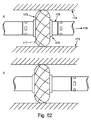
図62は、第1位置R及び第2位置Sにおける、一実施形態に係るモジュール型ロボット用の可動構成要素の概略図である。第1位置Rにおいて、アンカーモジュール173は展開されており、上側表面174と下側表面175との間の遠隔被操作アームを保持する。ブッシュ176は、半硬性リング177とシャシ構成要素178との間に設けられる。ブッシュ176により半硬性リング177をシャシ構成要素178に沿ってスライドさせることが可能となり、モジュール間の結合を超えてスライドさせることも可能となる。第2位置Sにおいて、半硬性リング177は、半硬性リング177を通じてスライドする遠隔被操作アームと共に図示され、同時に半硬性リング17が下側表面175及び上側表面174の両面から遠隔被操作アームを離すように保持する様子を図示している。
FIG. 62 is a schematic diagram of movable components for a modular robot according to an embodiment at a first position R and a second position S. FIG. In the first position R, the
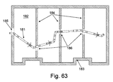
図63は、一実施形態に係る、床下空間におけるモジュール型ロボットの操作態様を示す概略図である。遠隔被操作アーム181は、複数のモジュールを備え、床下空間182にて操作される。この空間は、外壁183と内側寝台壁184との間の間隔により形成される。床下空間182の第1空間へのアクセスは、通気口185を通じて行われる。床下空間182の更なる一連の空間へのアクセスは、寝台壁184のギャップ186を通じて行われる。遠隔被操作アーム181を生成するモジュールには、アンカーモジュール、伸張シャシ・モジュール及びエルボ継手モジュールを含み、これらにより、床下空間182内で遠隔被操作アーム181を操作することが可能となる。
FIG. 63 is a schematic diagram illustrating an operation mode of the modular robot in the underfloor space according to the embodiment. The remotely operated
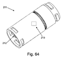
図64は、一実施形態に係る、モジュール間の電気的接続を示すモジュール型ロボットの概略図である。モジュール211は、1つのモジュールから次のモジュールに電力及び通信信号を伝達する電気コネクタ212を備える。マイクロ・コントローラが制御システムからの信号を処理することで、モジュール211内の異なる機能を作動させることができる。これらの機能は、特定のモジュールにより異なるが、例えば継手を回転させ又はアンカーを展開させるものである。この特定の実施形態において、モジュール211は回転可能なモジュールである。モジュール211は、一意識別子(UID)を備え、該一意識別子は、モジュールの現状に関するデータと共にモジュール211を同定するために制御装置に送信される。例えば、現状に関する情報には、モジュールの位置、回転、展開等を含むことができる。これにより、オペレータがアームを視認不可能なときでも、制御システムにて形成される遠隔被操作アームを視覚的に表示することが可能となる。
FIG. 64 is a schematic diagram of a modular robot showing electrical connections between modules according to one embodiment.
図64は、モジュールに対する電気的接続を示しているが、他のモジュールにおいて同様の原理を適用することができることは言うまでもない。更に、図64において特定の電気コネクタ212について上述したが、他の設計のコネクタを用いることもできる。いくつかの実施形態において、コネクタは、クイックリリース式コネクタ21に組み込むこともできる。更なる実施形態において、電気的接続は、例えば、赤外線又はBluetoothなどの無線接続であってもよい。いくつかの実施形態において、電力及び通信信号は、異なる経路を通じて伝達される。例えば、一実施形態において、電力はモジュールの間の物理的な電気的接続を用いて伝達されるが、命令信号を含む通信信号は、モジュール間における無線通信により伝達することができる。
FIG. 64 shows electrical connections to the modules, but it goes without saying that similar principles can be applied in other modules. Further, while specific
図65は、一実施形態に係るモジュール型ロボット1800の概略図である。図65のモジュール型ロボット1800の構成及び操作は、図1に示すモジュール型ロボットと同様である。当該実施形態において、モジュール型ロボット1800は、伸縮モジュール1801、エルボモジュール1802、カメラモジュール1803、シャシ・モジュール1804及びスプレーガンモジュール1805を備える。図65に示すモジュール1801〜1805の特定の組み合わせは、モジュールの可能な組み合わせを例示しているに過ぎない。雌型コネクタ1806及び雄型コネクタ1807をそれぞれ用いて、モジュール1801〜1805を相互結合させることで、図65に示すモジュール型ロボットを設けることができる。図66は、図65のモジュール型ロボットの雌型コネクタ1806の概略図であり、図67は、図65のモジュール型ロボットの雄型コネクタ1807の概略図である。雄型及び雌型コネクタ1806, 1807は、雄型コネクタ1807を雌型コネクタ1806に挿入し、直角にねじることで、インターロックすることができる。雄型及び雌型コネクタは、相互にロックさせ、雄型コネクタ1807上のボタン1808を押し、相互にコネクタを回転させることで解放させることができる。雄型及び雌型コネクタ1806, 1807により、機械的及び電気的に各モジュールを接続させることができる。
FIG. 65 is a schematic diagram of a
図68は、図65のモジュール型ロボット用の伸縮モジュール1801の概略図である。伸縮モジュール1801は、第2部分1810内に伸縮可能に収容される第1部分1809を備える。伸縮モジュール1801の伸張には、伸縮モジュール1801を伸張させるよう第2部分1810から第1部分1809を伸張させる、第1(第2)部分内の電気モータが作用する。第1部分1809が第2部分1810と係合することで、伸縮モジュール1801の長手方向軸線周りにおける第1及び第2部分間の相対回転を防止することができる。
FIG. 68 is a schematic view of the expansion /
図69は、図65のモジュール型ロボットのエルボモジュール1802の概略図である。エルボモジュール1802は、ステップモータに結合されるウォ―ム・ギアボックスを用いる動力継手、並びに正確な移動を可能とし、オペレータへの精密なフィードバックを提供するエンコーダを備える。
FIG. 69 is a schematic diagram of an
図70は、図65のモジュール型ロボットのカメラモジュール1803の概略図である。カメラモジュール1803は、カメラ1811及びその視野を照射するLED光源1812を備える。
FIG. 70 is a schematic diagram of the
図71は、実施形態に係るスプレー装置の概略図である。当該実施形態において、スプレー装置1900は、4つの自由回転可能なホイール1902を有するシャシ1901備える。ホール1903は、シャシ1901の上側表面に設けることで、制御ハンドル1905の取付コネクタ1904に結合することができる。取付コネクタ1904は、ピボット継手1906を通じて制御ハンドル1905に結合することができる。スプレーノズル1907は、シャシ1901の前方に取り付けることができ、所望のスプレーパターンを設けるために動力化される。図71の大きな矢印により示されるように、シャシ1901は、実質的に垂直な軸線周りにて取付コネクタ1904に対して枢動可能な構成を有する。同様に、制御ハンドル1905は、ピボット継手1906を通じて、実質的に平行な軸線周りの取付コネクタ1904に対して枢動可能な構成を有する。支点1907を制御ハンドル1905上に設ける。制御ハンドル1905の軸線周りにおける回転は、支点1907の角度位置により変化する。
FIG. 71 is a schematic diagram of a spray device according to an embodiment. In this embodiment, the
図72A〜図72Cに示すように、シャシ1901の長さに沿うホール1903の分布により、異なる領域に亘るスプレー装置の駆動を補助するよう、シャシ1901上の多様な位置にて取付コネクタ1904を取り付けることを可能となる。取付コネクタ1904は、(図72Aにおいて)シャシ1901の前方に取り付けられることで、制御ハンドル1905からの駆動力はシャシの中心部分から前方寄りの部分にかかる。このような構成により、領域内でスプレー装置を駆動するときのオペレータによる制御を簡易にすることができ、このような構成を有さず、後方から駆動する場合に車両方向が定まらなくなる。シャシの長さに沿う他の中間取付位置には、(図72Bに示すように)地形先導制御機構用に中心部にピボットを取り付けることを含む、あるいは、(図72Cに示すように)シャシ1902の後方にピボットを取り付けることも含む。
72A-72C, mounting
図71に示す実施形態の多様な実施例として、第2取付コネクタを第1取付コネクタ1904から離れた位置にてシャシ1901に取り付けることもできる。例えば、シャシ1901の前後方向に対する横方向に取り付けることもできる。第2取付コネクタ1904は、第2制御ハンドル1905に結合することができる。このようにして、スプレー装置1900の位置は、2つの制御ハンドルの力及び方向を個別に変化させることで、制御することができる。制御ハンドルは、伸縮機構(図示せず)を通じて、あるいは、ハンドルに付加的なモジュール長さを付加することで、伸張させることできる。
As various examples of the embodiment shown in FIG. 71, the second attachment connector can be attached to the
図73A〜図73Cは、図71のスプレー装置1900の支点1907操作態様を示す概略図である。図73A〜図73Cに示すように、制御ハンドル1905は、その長さに沿って、シャシに対して回転させることできる。このようにして、支点1907は、(図73に示すように)後輪を持ち上げるよう、地面と係合することができる。ホイールの側方における地面との摩擦が低減されることで、スプレー装置の再配置又は方向付けが簡易になる。
73A to 73C are schematic views showing the operation mode of the
本発明に係る電気機械的アーム及びスプレーガンは、多様な用途にて用いることができる。例えば、床下断熱材、あるいは、ロフト及び屋根の断熱材をスプレーするとき、すなわち、ロフト及び天井空間などのアクセスが難しい場所への断熱材の塗布に用いることができる。アームは、空間及び空洞に防音材を遠隔から塗布するために用いることでき、例えば、アパートの床間に用いることができる。アーム及びスプレーガンは、防カビ剤などの防腐剤、木材の保存防腐剤及び他の材料を塗布するために用いることができる。アーム及びスプレーガンは、産業的な用途で用いることができ、例えば、塗料、保護塗装、防水剤を塗布し、あるいは、ひび割れ又は損傷を受けたパイプ、貯蔵タンク及び他の産業構造物を、保全及び修理するために用いることができる。アームは、建築物の点検及び保全に用いることができ、これには、測量、マッピング、そして、例えばアスベスト測量又はワイヤの点検など危険な「クロールスペース」の点検、例えばパイプ点検及び漏洩点検などの測量サービス、並びに構造測量を含む。アームは、インフラの点検及び保全に用いることができ、例えば裁縫器具、ガスパイプの測量、圧力タンクの点検に用いることができる。 The electromechanical arm and spray gun according to the present invention can be used in various applications. For example, it can be used for spraying underfloor insulation or loft and roof insulation, that is, for applying insulation to difficult to access places such as lofts and ceiling spaces. Arms can be used to remotely apply soundproofing material to spaces and cavities, for example, between apartment floors. Arms and spray guns can be used to apply preservatives such as fungicides, wood preservatives and other materials. Arms and spray guns can be used in industrial applications, for example, paints, protective coatings, water proofing, or preserving cracked or damaged pipes, storage tanks and other industrial structures And can be used for repair. Arms can be used for building inspection and maintenance, including surveying, mapping, and inspection of dangerous “crawl space” such as asbestos surveying or wire inspection, such as pipe inspection and leak inspection. Includes surveying services as well as structural surveying. The arm can be used for infrastructure inspection and maintenance, for example, sewing instruments, gas pipe surveying, pressure tank inspection.
スプレーされる材料には、ポリウレタンスプレー材料を含むことができ、例えばBASF社のWALLTITEのように伸張する2部の絶縁材料、(Saint-Gobain社、シュレンヌ、フランスの製品であるCOATWOOLのような)鉱物綿、表面を接着用の結着剤含有/非含有のセルロース絶縁材料、スプレーエアロゲル絶縁塗料、防音材、防カビ剤、ポリウレタンスプレー材料、塗料及び塗装剤などを含んでいてもよい。 The material to be sprayed can include polyurethane spray material, for example, two parts of insulating material, such as BASF WALLTITE (such as Saint-Gobain, Shrennes, French product COATWOOL) It may contain a mineral cotton, a cellulose insulating material containing or not containing a binder for bonding the surface, a spray airgel insulating paint, a soundproofing material, a fungicide, a polyurethane spray material, a paint and a coating agent.
本明細書の実施形態は、床下空間での使用に関して記載したものであるが、言うまでもなく、開示された電気機械的アームは他の空間においても使用することができる。例えば、床間の空間、壁間の空間において用いることができる。典型的には、電気機械的アームは、人間がアクセスするのが困難なあらゆる種類の空間を指すクロールスペースとして知られる空間で用いることができる。 Although the embodiments herein are described for use in an underfloor space, it will be appreciated that the disclosed electromechanical arm can be used in other spaces. For example, it can be used in a space between floors and a space between walls. Typically, an electromechanical arm can be used in a space known as a crawl space that refers to any type of space that is difficult for humans to access.
要するに、表面上に材料をスプレーするための装置は、遠位端及び近位端を有する少なくとも1つの伸張部材、スプレーパターンにて材料をスプレーするよう伸張部材の遠位端に取り付けられ、伸張部材の近位端におけるスプレー材料入口部に結合される少なくとも1つのスプレーノズル、伸張部材の遠位端に取り付けられ、伸張部材の近位端のカメラ出力部に結合されて、スプレーパターンの画像を取り込むよう構成されたカメラ、伸張部材の近位端からスプレーノズルの操作を制御するよう構成された制御機構を備える。 In summary, an apparatus for spraying material onto a surface is attached to the distal end of the stretch member to spray material in a spray pattern, at least one stretch member having a distal end and a proximal end. At least one spray nozzle coupled to the spray material inlet at the proximal end of the extension member attached to the distal end of the extension member and coupled to the camera output at the proximal end of the extension member to capture an image of the spray pattern And a control mechanism configured to control operation of the spray nozzle from the proximal end of the extension member.
本明細書には、複数の相互結合可能なモジュール2, 4, 5, 7, 8を備えるモジュール型ロボットが開示されている。各モジュールは、その第1端に第1機械コネクタを、その第2端には第2機械コネクタを備え、第1電気コネクタ及び第2電気コネクタが、モジュールの端部同士を接続するよう非恒久的に相互係合可能であることで、所望の構成下でモジュール型ロボットを形成することができる。各モジュールは、第1構成要素、第2構成要素、並びに第1構成要素を第2構成要素に対して移動させるためのモータを備える。各モジュールは、制御信号を受信し、該制御信号に応答してモータの制御操作を行うコントローラを備える。
The present specification discloses a modular robot comprising a plurality of
本明細書に開示する発明は、スプレーノズルを取り付ける装置であって、該装置は、近位端に設けられ、ハンドルを有する伸長部材及び遠位端に設けられ、スプレーノズル用の取付部を有する伸張部材を備え、該装置は、表面上の伸張部材を支持するために伸張部材に取り付けられたホイール・キャリッジを更に備え、該キャリッジは、長手方向の伸張部材に対して固定されており、該伸張部材は、該キャリッジに対して長手方向軸線周りにて回転可能である。この伸張部材は、伸張可能である。 The invention disclosed herein is an apparatus for attaching a spray nozzle, the apparatus being provided at a proximal end, provided with an elongated member having a handle and at a distal end, and having an attachment for the spray nozzle. An extension member, the apparatus further comprising a wheel carriage attached to the extension member to support the extension member on the surface, the carriage being fixed relative to the longitudinal extension member; The extension member is rotatable about a longitudinal axis relative to the carriage. The extension member is extendable.
本明細書及び特許請求の範囲の全体にわたり、「備える」「有する」「持つ」「設ける」という単語及びこれらのバリエーションは「含む、がそれのみに限定されるものではない」ことを意味し、他の部分、添加物、要素、数又は工程を排除することを意図するもの(排除するもの)ではない。本明細書及び特許請求の範囲の全体わたり、文脈で特に要求されない限り、単数形は複数形を包含する。特に、不定冠詞を使用している場合、文脈で特に要求されない限り、明細書は、単数形のみならず複数形も考慮するものと解すべきである。 Throughout this specification and the claims, the words “comprising”, “having”, “having”, “providing” and variations thereof mean “including but not limited to”, It is not intended to exclude (exclude) other parts, additives, elements, numbers or steps. Unless otherwise required by context and specification, the singular forms include the plural forms. In particular, where indefinite articles are used, the specification should be understood to consider the singular as well as the plural unless the context requires otherwise.
本発明の特定の態様、実施形態又は例示と併せて記述されている図面、数字、特徴又は群は、相互に矛盾が生じない限り、本明細書に記述されている任意の他の態様、実施形態又は例示にも当てはまるものと解すべきである。本明細書に開示されている全ての特徴は(任意の請求項、要約書及び図面を含む)、任意の組み合わせに結合できる。但し、少なくともそのような特徴及び/又は工程のうちのいくつかが相互に排他的である組み合わせは除外される。本発明は、これまでに説明した任意の実施形態の詳細に制限されるものではない。本発明は、本明細書(任意の請求項、要約書及び図面を含む)に開示される特徴の任意の新規発明、又は任意の新規組み合わせに拡張する。
The drawings, numbers, features, or groups described in conjunction with a particular aspect, embodiment, or illustration of the invention, are not limited to any other aspect, implementation described herein unless they contradict each other. It should be understood that this also applies to the form or illustration. All features disclosed in this specification (including any claims, abstracts and drawings) can be combined in any combination. However, combinations where at least some of such features and / or steps are mutually exclusive are excluded. The invention is not limited to the details of any embodiment described above. The present invention extends to any new invention or any new combination of features disclosed herein (including any claims, abstracts and drawings).
Claims (37)
遠位端及び近位端を有する少なくとも1つの伸張部材と;
所定のスプレーパターンにて前記材料をスプレーするよう、前記伸張部材の遠位端に取り付けられ、前記伸張部材の近位端におけるスプレー材料入口部に結合される少なくとも1つのスプレーノズルと;
前記伸張部材の遠位端に取り付けられ、前記伸張部材の近位端におけるカメラ出力部に結合されて前記スプレーパターンの画像を取り込むよう構成されたカメラと;
前記伸張部材の近位端から前記スプレーノズルの操作を制御するよう構成された制御機構と;
を備える、装置。 A device for spraying material onto a surface:
At least one extension member having a distal end and a proximal end;
At least one spray nozzle attached to the distal end of the extension member and coupled to a spray material inlet at the proximal end of the extension member to spray the material in a predetermined spray pattern;
A camera attached to a distal end of the extension member and coupled to a camera output at a proximal end of the extension member to capture an image of the spray pattern;
A control mechanism configured to control operation of the spray nozzle from a proximal end of the extension member;
An apparatus comprising:
各モジュールが、その第1端に第1機械的コネクタを、第2端には第2機械的コネクタを備え、前記第1機械的コネクタ及び前記第2機械的コネクタが、所望の構造のモジュール型ロボットを形成すべく、前記モジュールの端部同士を結合するよう非永久的に相互係合可能であり;
各モジュールが、第1構成要素、第2構成要素、並びに前記第1構成要素を前記第2構成要素に対して移動させるためのモータを備え;
各モジュールが、制御信号を受信し、該制御信号に応答して前記モータの制御操作を行うコントローラを備える、モジュール型ロボット。 A modular robot with a plurality of interconnectable modules:
Each module includes a first mechanical connector at a first end and a second mechanical connector at a second end, and the first mechanical connector and the second mechanical connector are modular in a desired structure. Non-permanently interengageable to join the ends of the modules to form a robot;
Each module comprises a first component, a second component, and a motor for moving the first component relative to the second component;
A module-type robot in which each module includes a controller that receives a control signal and controls the motor in response to the control signal.
Applications Claiming Priority (6)
| Application Number | Priority Date | Filing Date | Title |
|---|---|---|---|
| GB1418824.7A GB2531576B (en) | 2014-10-22 | 2014-10-22 | Modular Robot |
| GB1418824.7 | 2014-10-22 | ||
| GB1512225.2A GB2535817B (en) | 2014-10-22 | 2015-07-13 | Spray nozzle arm |
| GB1512225.2 | 2015-07-13 | ||
| PCT/GB2015/053175 WO2016063074A2 (en) | 2014-10-22 | 2015-10-22 | Robotic device |
| GB1607338.9A GB2540652B (en) | 2014-10-22 | 2016-04-27 | Remotely operated device |
Publications (2)
| Publication Number | Publication Date |
|---|---|
| JP2017536976A true JP2017536976A (en) | 2017-12-14 |
| JP2017536976A5 JP2017536976A5 (en) | 2018-10-18 |
Family
ID=66675329
Family Applications (1)
| Application Number | Title | Priority Date | Filing Date |
|---|---|---|---|
| JP2017522074A Pending JP2017536976A (en) | 2014-10-22 | 2015-10-22 | Robot equipment |
Country Status (7)
| Country | Link |
|---|---|
| US (3) | US10569288B2 (en) |
| EP (2) | EP3209466B1 (en) |
| JP (1) | JP2017536976A (en) |
| AU (2) | AU2015334693B2 (en) |
| CA (2) | CA3001087C (en) |
| GB (5) | GB2531576B (en) |
| WO (2) | WO2016063074A2 (en) |
Cited By (1)
| Publication number | Priority date | Publication date | Assignee | Title |
|---|---|---|---|---|
| JP2020076585A (en) * | 2018-11-05 | 2020-05-21 | 倉敷紡績株式会社 | Measuring method of three-dimensional shape of coating material, measuring system of three-dimensional shape of coating material, and application method of coating material |
Families Citing this family (49)
| Publication number | Priority date | Publication date | Assignee | Title |
|---|---|---|---|---|
| GB2531576B (en) * | 2014-10-22 | 2018-04-25 | Q Bot Ltd | Modular Robot |
| EP3275393A4 (en) * | 2015-03-25 | 2018-11-21 | Sony Olympus Medical Solutions Inc. | Medical observation device, surgical observation device, and medical observation system |
| GB2539661B (en) | 2015-06-22 | 2019-06-26 | Q Bot Ltd | Robotic Vehicle |
| FR3050672B1 (en) * | 2016-04-29 | 2018-11-23 | Les Companions | AUTOMATE FOR TREATING A SURFACE |
| FR3054578B1 (en) * | 2016-07-27 | 2021-12-24 | Soletanche Freyssinet | METHOD FOR REPAIRING A CIVIL ENGINEERING WORK |
| US10801186B2 (en) * | 2016-08-04 | 2020-10-13 | Operations Technology Development, Nfp | Integrated system and method to determine activity of excavation machinery |
| CN106694319B (en) * | 2017-03-22 | 2019-06-18 | 京东方科技集团股份有限公司 | Curved surface apparatus for coating and automatic double surface gluer |
| EP3600789A4 (en) | 2017-03-31 | 2021-01-06 | Canvas Construction, Inc. | Automated drywall mudding system and method |
| JP7325420B2 (en) | 2017-09-25 | 2023-08-14 | キャンヴァス コンストラクション インコーポレイテッド | Automatic wall finishing system and method |
| CN207266563U (en) * | 2017-09-29 | 2018-04-24 | 好得科技(深圳)有限公司 | A kind of Multifunction infrared senses water sprinkler |
| CN108274458B (en) * | 2017-12-19 | 2020-12-18 | 北京可以科技有限公司 | Subunit module for building modular robot |
| WO2020010142A1 (en) * | 2018-07-02 | 2020-01-09 | Kurion, Inc. | Systems and methods for cleaning and maintenance of tanks |
| TWI700159B (en) * | 2018-09-07 | 2020-08-01 | 中華電信股份有限公司 | External wall waterproof tapping implementation system and method thereof |
| CN109158239A (en) * | 2018-09-29 | 2019-01-08 | 广东海洋大学 | A kind of pipe inner-wall spraying robot |
| US11707819B2 (en) | 2018-10-15 | 2023-07-25 | General Electric Company | Selectively flexible extension tool |
| GB201820507D0 (en) * | 2018-12-17 | 2019-01-30 | Rolls Royce Plc | Positioning device |
| JP2022522067A (en) | 2019-02-21 | 2022-04-13 | キャンヴァス コンストラクション インコーポレイテッド | Surface finish quality evaluation system and method |
| WO2020178663A1 (en) | 2019-03-01 | 2020-09-10 | Precision Planting Llc | Agricultural spraying system |
| FI130507B (en) * | 2019-04-08 | 2023-10-13 | Normet Oy | Definition system for defining a spraying area for a spraying machine |
| GB201908845D0 (en) * | 2019-06-20 | 2019-08-07 | Railscape Holdings Ltd | Improvements in or relating to herbicide delivery |
| CN110479522A (en) * | 2019-07-15 | 2019-11-22 | 徐州世澳木业有限公司 | Paint spraying machine suitable for wood industry |
| US20220330537A1 (en) | 2019-09-27 | 2022-10-20 | Precision Planting Llc | Agricultural spraying system |
| US10802121B1 (en) * | 2019-10-09 | 2020-10-13 | Ford Global Technologies, Llc | Cleaning apparatus for sensor |
| WO2021071811A1 (en) * | 2019-10-11 | 2021-04-15 | Covestro Llc | Methods, systems and computer program products for production and application of spray foam using optical and infrared imaging |
| CN110802609B (en) * | 2019-11-02 | 2020-12-04 | 江苏锦程航空科技有限公司 | Security protection intelligent robot |
| US11752622B2 (en) | 2020-01-23 | 2023-09-12 | General Electric Company | Extension tool having a plurality of links |
| US11692650B2 (en) | 2020-01-23 | 2023-07-04 | General Electric Company | Selectively flexible extension tool |
| US11642687B2 (en) * | 2020-02-13 | 2023-05-09 | Covestro Llc | Methods and systems for manufacturing foam wall structures |
| US11371437B2 (en) | 2020-03-10 | 2022-06-28 | Oliver Crispin Robotics Limited | Insertion tool |
| CN111468350A (en) * | 2020-04-06 | 2020-07-31 | 薛丽 | Paint spraying device for cartoon toy and using method |
| CN111451041B (en) * | 2020-04-11 | 2021-07-30 | 宁波润爵科技有限公司 | Curved lamp pole painting device pulled by steel wire rope |
| NO346361B1 (en) * | 2020-04-29 | 2022-06-27 | Conrobotix As | CONTROL SYSTEM FOR OPERATING WORKING OPERATIONS WITH TOOLS IN A ROBOT ADAPTED FOR TOOL HANDLING |
| CN111546337B (en) * | 2020-04-30 | 2022-02-11 | 重庆见芒信息技术咨询服务有限公司 | Industrial robot full-coverage path generation method and system based on free-form surface |
| CN111975793A (en) * | 2020-08-17 | 2020-11-24 | 哈尔滨理工大学 | Felling bamboo moving mechanical arm system based on multi-task cooperative work |
| EP4204639A1 (en) | 2020-08-28 | 2023-07-05 | Stepan Company | Systems and methods for computer vision assisted foam board processing |
| FR3115492B1 (en) * | 2020-10-22 | 2022-11-25 | Inst Polytechnique Grenoble | Process for printing conductive tracks on an object and associated electronic functionalization process |
| CN112604858A (en) * | 2020-12-02 | 2021-04-06 | 南通大学技术转移中心 | Telescopic manipulator of coating robot for ship |
| JP2022099457A (en) * | 2020-12-23 | 2022-07-05 | 郁子 鈴木 | Container hooking bar and method of use thereof |
| US11951893B2 (en) | 2020-12-23 | 2024-04-09 | Ford Global Technologies, Llc | Interlocking reconfigurable modular lockers |
| US11654547B2 (en) * | 2021-03-31 | 2023-05-23 | General Electric Company | Extension tool |
| DE102021003027A1 (en) | 2021-06-15 | 2022-12-15 | TRO GmbH | Telescopic spray lance for cleaning building facades |
| CN113335528B (en) * | 2021-06-24 | 2023-05-19 | 江西维普产业技术研究服务有限公司 | Mapping unmanned aerial vehicle based on 5G communication |
| CN113681590B (en) * | 2021-08-27 | 2022-09-09 | 中国矿业大学 | Modular robot docking device and docking method |
| EP4201603A1 (en) * | 2021-12-21 | 2023-06-28 | Rolls-Royce plc | Means for stiffening a continuum arm robot |
| EP4201610A1 (en) * | 2021-12-21 | 2023-06-28 | Rolls-Royce plc | Continuum robot stiffening |
| DE102022100389A1 (en) | 2022-01-10 | 2023-07-13 | Bayerische Motoren Werke Aktiengesellschaft | System and method for recording application data in real time |
| CN114433377B (en) * | 2022-04-11 | 2022-06-21 | 烟台锐铭金属材料有限公司 | Multi-axis spraying device for coating preparation |
| CN115338051B (en) * | 2022-08-15 | 2023-07-25 | 中国建筑第五工程局有限公司 | Building vent shower nozzle equipment |
| CN116116623B (en) * | 2023-04-13 | 2023-07-04 | 晋江市兰欣新材料科技有限公司 | Spraying equipment and spraying process for anti-corrosion paint |
Citations (8)
| Publication number | Priority date | Publication date | Assignee | Title |
|---|---|---|---|---|
| JPS4876932A (en) * | 1972-01-17 | 1973-10-16 | ||
| JPH07197554A (en) * | 1993-12-29 | 1995-08-01 | Nishimatsu Constr Co Ltd | Autonomously traveling type intelligent work robot |
| JP2002349074A (en) * | 2001-05-21 | 2002-12-04 | Sekisui House Ltd | Under floor check method for house and floor structure having under floor checking open-and-close plug hole |
| US20060283981A1 (en) * | 2005-06-16 | 2006-12-21 | Mead William T | Spray coating nozzle assembly for coating remote areas |
| JP2011254839A (en) * | 2011-09-12 | 2011-12-22 | Koshii Preserving:Kk | Treating device of termite control |
| US20130073089A1 (en) * | 2011-09-15 | 2013-03-21 | Kabushiki Kaisha Yaskawa Denki | Robot system and imaging method |
| JP2013240851A (en) * | 2012-05-18 | 2013-12-05 | Tokyu Construction Co Ltd | Observation tool |
| JP2014193032A (en) * | 2013-03-27 | 2014-10-06 | Nippon Telegraph & Telephone East Corp | Wiring tool, detection method of wiring, and extraction method of wiring |
Family Cites Families (30)
| Publication number | Priority date | Publication date | Assignee | Title |
|---|---|---|---|---|
| US2607622A (en) * | 1950-03-03 | 1952-08-19 | Leila M Doepke | Hose attachment |
| JPS5479104A (en) | 1977-12-08 | 1979-06-23 | Kurosaki Refractories Co | Lining apparatus equipped with television camera |
| US4323196A (en) * | 1980-02-22 | 1982-04-06 | Logue Gerald W | Paint spraying apparatus |
| US4641780A (en) * | 1981-06-29 | 1987-02-10 | Smrt Thomas John | Spraying apparatus |
| US4926522A (en) * | 1989-04-18 | 1990-05-22 | Wei Wang | Utility tools |
| US5108655A (en) * | 1989-05-30 | 1992-04-28 | Electro-System, Incorporated | Foam monitoring control system |
| US5625464A (en) | 1990-03-16 | 1997-04-29 | Thomson Consumer Electronics | Continuous television transmission reproduction and playback |
| JPH0757577A (en) * | 1993-08-09 | 1995-03-03 | Fujikura Ltd | Washing device for apparatus for overhead power distribution line |
| JPH10337544A (en) * | 1997-06-05 | 1998-12-22 | Mitsubishi Heavy Ind Ltd | Waterway inspection device |
| JP2000246205A (en) * | 1999-03-02 | 2000-09-12 | Shimizu Corp | Apparatus for removing scale |
| US6929198B2 (en) * | 2002-07-23 | 2005-08-16 | Devilbiss Air Power Company | Pressure washer assembly |
| US6889920B2 (en) * | 2003-03-17 | 2005-05-10 | Westinghouse Savannah River Company | Directed spray mast |
| DE202004018903U1 (en) * | 2004-01-15 | 2005-03-10 | Suttner Gmbh & Co. Kg | Spray lance for a high-pressure cleaning device and joint for a nozzle of a high-pressure cleaning device |
| US7182223B2 (en) * | 2004-03-29 | 2007-02-27 | S.C. Johnson & Son, Inc. | Detachable tube assembly |
| US7121484B2 (en) * | 2004-08-17 | 2006-10-17 | Howard Daley | Carriage for a power washer wand |
| DE102006031294A1 (en) * | 2006-06-29 | 2008-01-03 | Fisw Steuerungstechnik Gmbh | Device for guidance and retaining of medical and surgical instruments, has two tubular modules, where one of tubular modules is tilting rotary module and modules are arbitrarily combined |
| US8086042B2 (en) * | 2006-12-29 | 2011-12-27 | Johns Manville | Weatherization imaging systems and methods |
| US20080257908A1 (en) | 2007-04-23 | 2008-10-23 | Reelick Eugene A | Liquid dispensing device |
| KR20100108921A (en) * | 2009-03-31 | 2010-10-08 | 이윤희 | A fire engine |
| WO2011041875A1 (en) * | 2009-10-07 | 2011-04-14 | John Roy Kirkpatrick | Pressure washer crutch |
| EP2531327A4 (en) * | 2010-02-05 | 2014-08-06 | Univ California | Four degree of freedom (4-dof) single modular robot unit or joint |
| US20120072035A1 (en) * | 2010-09-17 | 2012-03-22 | Steven Nielsen | Methods and apparatus for dispensing material and electronically tracking same |
| KR101206766B1 (en) * | 2011-12-21 | 2012-12-05 | 김소희 | High-pressure injection system |
| CN102696570A (en) * | 2012-06-18 | 2012-10-03 | 中国农业大学 | Flexibly operable hand-eye mode spraying robot device |
| CA2845168A1 (en) * | 2013-03-01 | 2014-09-01 | Envirosight Llc | Nozzle-mounted camera system and method |
| JP6731338B2 (en) * | 2013-05-23 | 2020-07-29 | キュー−ボット リミテッドQ−Bot Limited | Building surface coating method and robot therefor |
| US8757514B1 (en) * | 2013-07-11 | 2014-06-24 | Rick Perello | Spray system with remote target inspection and actuation |
| WO2015172131A1 (en) | 2014-05-09 | 2015-11-12 | Carnegie Mellon University | Systems and methods for modular units in electro-mechanical systems |
| GB2531576B (en) * | 2014-10-22 | 2018-04-25 | Q Bot Ltd | Modular Robot |
| CN204220360U (en) * | 2014-10-28 | 2015-03-25 | 温玉桂 | Spray-painting plant |
-
2014
- 2014-10-22 GB GB1418824.7A patent/GB2531576B/en active Active
-
2015
- 2015-07-13 GB GB1711477.8A patent/GB2551064B/en active Active
- 2015-07-13 GB GB1512225.2A patent/GB2535817B/en active Active
- 2015-07-13 GB GB1711479.4A patent/GB2551282B/en active Active
- 2015-10-22 US US15/517,382 patent/US10569288B2/en active Active
- 2015-10-22 WO PCT/GB2015/053175 patent/WO2016063074A2/en active Application Filing
- 2015-10-22 CA CA3001087A patent/CA3001087C/en active Active
- 2015-10-22 EP EP15791014.2A patent/EP3209466B1/en active Active
- 2015-10-22 JP JP2017522074A patent/JP2017536976A/en active Pending
- 2015-10-22 AU AU2015334693A patent/AU2015334693B2/en active Active
-
2016
- 2016-04-27 GB GB1607338.9A patent/GB2540652B/en active Active
- 2016-07-13 AU AU2016293309A patent/AU2016293309B2/en active Active
- 2016-07-13 CA CA2991683A patent/CA2991683C/en active Active
- 2016-07-13 US US15/743,182 patent/US10675648B2/en active Active
- 2016-07-13 WO PCT/GB2016/052116 patent/WO2017009642A1/en active Application Filing
- 2016-07-13 EP EP16753415.5A patent/EP3322563B1/en active Active
-
2019
- 2019-11-26 US US16/696,490 patent/US11059065B2/en active Active
Patent Citations (9)
| Publication number | Priority date | Publication date | Assignee | Title |
|---|---|---|---|---|
| JPS4876932A (en) * | 1972-01-17 | 1973-10-16 | ||
| JPH07197554A (en) * | 1993-12-29 | 1995-08-01 | Nishimatsu Constr Co Ltd | Autonomously traveling type intelligent work robot |
| JP2002349074A (en) * | 2001-05-21 | 2002-12-04 | Sekisui House Ltd | Under floor check method for house and floor structure having under floor checking open-and-close plug hole |
| US20060283981A1 (en) * | 2005-06-16 | 2006-12-21 | Mead William T | Spray coating nozzle assembly for coating remote areas |
| JP2011254839A (en) * | 2011-09-12 | 2011-12-22 | Koshii Preserving:Kk | Treating device of termite control |
| US20130073089A1 (en) * | 2011-09-15 | 2013-03-21 | Kabushiki Kaisha Yaskawa Denki | Robot system and imaging method |
| JP2013063474A (en) * | 2011-09-15 | 2013-04-11 | Yaskawa Electric Corp | Robot system and imaging method |
| JP2013240851A (en) * | 2012-05-18 | 2013-12-05 | Tokyu Construction Co Ltd | Observation tool |
| JP2014193032A (en) * | 2013-03-27 | 2014-10-06 | Nippon Telegraph & Telephone East Corp | Wiring tool, detection method of wiring, and extraction method of wiring |
Cited By (1)
| Publication number | Priority date | Publication date | Assignee | Title |
|---|---|---|---|---|
| JP2020076585A (en) * | 2018-11-05 | 2020-05-21 | 倉敷紡績株式会社 | Measuring method of three-dimensional shape of coating material, measuring system of three-dimensional shape of coating material, and application method of coating material |
Also Published As
Similar Documents
| Publication | Publication Date | Title |
|---|---|---|
| JP2017536976A (en) | Robot equipment | |
| EP3310494B1 (en) | Robotic vehicle | |
| US11298200B2 (en) | Techniques for operating a kinematic structure by manual motion of link coupled to the kinematic structure | |
| US11723733B2 (en) | Limited movement of a surgical mounting platform controlled by manual motion of robotic arms | |
| JP5785538B2 (en) | Robot system for laparoscopic surgery | |
| US8464820B2 (en) | Air cushion platform for carrying a manipulator arm and movable robot | |
| JP2016526121A (en) | Building surface coating method and robot therefor | |
| WO2020237397A1 (en) | Method and system for mobile reconfigurable robot for a large workspace | |
| GB2573061A (en) | Robotic vehicle | |
| JP2008155338A (en) | Work assisting device and composite pantograph mechanism | |
| JP3397317B2 (en) | Force feedback type steering device | |
| WO2023210730A1 (en) | Robot | |
| US11958192B2 (en) | Method and system for mobile reconfigurable robot for a large workspace | |
| JP6861115B2 (en) | Self-propelled scaffolding | |
| WO2015024579A1 (en) | Robot manipulated viewpoint | |
| RU2260543C2 (en) | Vehicle for movement along surface arbitrary orientated in space |
Legal Events
| Date | Code | Title | Description |
|---|---|---|---|
| A521 | Request for written amendment filed |
Free format text: JAPANESE INTERMEDIATE CODE: A523 Effective date: 20180910 |
|
| A621 | Written request for application examination |
Free format text: JAPANESE INTERMEDIATE CODE: A621 Effective date: 20180910 |
|
| A977 | Report on retrieval |
Free format text: JAPANESE INTERMEDIATE CODE: A971007 Effective date: 20190920 |
|
| A131 | Notification of reasons for refusal |
Free format text: JAPANESE INTERMEDIATE CODE: A131 Effective date: 20191001 |
|
| A521 | Request for written amendment filed |
Free format text: JAPANESE INTERMEDIATE CODE: A523 Effective date: 20191205 |
|
| A131 | Notification of reasons for refusal |
Free format text: JAPANESE INTERMEDIATE CODE: A131 Effective date: 20200512 |
|
| A02 | Decision of refusal |
Free format text: JAPANESE INTERMEDIATE CODE: A02 Effective date: 20201208 |