JP2017531475A - Footwear product upper incorporating fabric components with stretch elements - Google Patents
Footwear product upper incorporating fabric components with stretch elements Download PDFInfo
- Publication number
- JP2017531475A JP2017531475A JP2017516480A JP2017516480A JP2017531475A JP 2017531475 A JP2017531475 A JP 2017531475A JP 2017516480 A JP2017516480 A JP 2017516480A JP 2017516480 A JP2017516480 A JP 2017516480A JP 2017531475 A JP2017531475 A JP 2017531475A
- Authority
- JP
- Japan
- Prior art keywords
- segment
- knit
- extensible
- fabric
- extensible element
- Prior art date
- Legal status (The legal status is an assumption and is not a legal conclusion. Google has not performed a legal analysis and makes no representation as to the accuracy of the status listed.)
- Granted
Links
- 239000004744 fabric Substances 0.000 title claims abstract description 131
- 210000002683 foot Anatomy 0.000 claims description 102
- 238000000034 method Methods 0.000 claims description 40
- 238000009940 knitting Methods 0.000 claims description 18
- 210000000452 mid-foot Anatomy 0.000 claims description 15
- 230000008859 change Effects 0.000 claims description 11
- 210000001872 metatarsal bone Anatomy 0.000 claims description 5
- 230000037361 pathway Effects 0.000 claims description 4
- 210000003371 toe Anatomy 0.000 description 28
- 239000000463 material Substances 0.000 description 27
- 230000008569 process Effects 0.000 description 20
- 230000002093 peripheral effect Effects 0.000 description 11
- 230000007704 transition Effects 0.000 description 8
- 238000004519 manufacturing process Methods 0.000 description 7
- 239000000853 adhesive Substances 0.000 description 6
- 230000001070 adhesive effect Effects 0.000 description 6
- 238000005520 cutting process Methods 0.000 description 5
- 238000009958 sewing Methods 0.000 description 5
- 230000008901 benefit Effects 0.000 description 4
- 239000002699 waste material Substances 0.000 description 4
- 210000003423 ankle Anatomy 0.000 description 3
- 229920003235 aromatic polyamide Polymers 0.000 description 3
- 238000005452 bending Methods 0.000 description 3
- 230000000694 effects Effects 0.000 description 3
- 230000009191 jumping Effects 0.000 description 3
- 230000007935 neutral effect Effects 0.000 description 3
- 229920002334 Spandex Polymers 0.000 description 2
- 238000005299 abrasion Methods 0.000 description 2
- 239000004760 aramid Substances 0.000 description 2
- 230000000386 athletic effect Effects 0.000 description 2
- 230000005540 biological transmission Effects 0.000 description 2
- 239000000835 fiber Substances 0.000 description 2
- 239000012530 fluid Substances 0.000 description 2
- 230000001965 increasing effect Effects 0.000 description 2
- 229920000728 polyester Polymers 0.000 description 2
- 125000006850 spacer group Chemical group 0.000 description 2
- 229920000742 Cotton Polymers 0.000 description 1
- 229920000106 Liquid crystal polymer Polymers 0.000 description 1
- 239000004977 Liquid-crystal polymers (LCPs) Substances 0.000 description 1
- 239000004677 Nylon Substances 0.000 description 1
- 229920000297 Rayon Polymers 0.000 description 1
- 239000004699 Ultra-high molecular weight polyethylene Substances 0.000 description 1
- 238000004026 adhesive bonding Methods 0.000 description 1
- 238000001035 drying Methods 0.000 description 1
- 230000002708 enhancing effect Effects 0.000 description 1
- 239000006261 foam material Substances 0.000 description 1
- 239000011521 glass Substances 0.000 description 1
- 230000001788 irregular Effects 0.000 description 1
- 238000005304 joining Methods 0.000 description 1
- 239000010985 leather Substances 0.000 description 1
- 238000012986 modification Methods 0.000 description 1
- 230000004048 modification Effects 0.000 description 1
- 229920001778 nylon Polymers 0.000 description 1
- 229920000642 polymer Polymers 0.000 description 1
- 239000002964 rayon Substances 0.000 description 1
- 230000003068 static effect Effects 0.000 description 1
- 239000004753 textile Substances 0.000 description 1
- 229920000785 ultra high molecular weight polyethylene Polymers 0.000 description 1
- 238000004804 winding Methods 0.000 description 1
- -1 wool Polymers 0.000 description 1
- 210000002268 wool Anatomy 0.000 description 1
Images


Classifications
-
- A—HUMAN NECESSITIES
- A43—FOOTWEAR
- A43B—CHARACTERISTIC FEATURES OF FOOTWEAR; PARTS OF FOOTWEAR
- A43B23/00—Uppers; Boot legs; Stiffeners; Other single parts of footwear
- A43B23/02—Uppers; Boot legs
- A43B23/0245—Uppers; Boot legs characterised by the constructive form
-
- A—HUMAN NECESSITIES
- A43—FOOTWEAR
- A43B—CHARACTERISTIC FEATURES OF FOOTWEAR; PARTS OF FOOTWEAR
- A43B1/00—Footwear characterised by the material
- A43B1/02—Footwear characterised by the material made of fibres or fabrics made therefrom
- A43B1/04—Footwear characterised by the material made of fibres or fabrics made therefrom braided, knotted, knitted or crocheted
-
- A—HUMAN NECESSITIES
- A43—FOOTWEAR
- A43B—CHARACTERISTIC FEATURES OF FOOTWEAR; PARTS OF FOOTWEAR
- A43B23/00—Uppers; Boot legs; Stiffeners; Other single parts of footwear
- A43B23/02—Uppers; Boot legs
-
- A—HUMAN NECESSITIES
- A43—FOOTWEAR
- A43B—CHARACTERISTIC FEATURES OF FOOTWEAR; PARTS OF FOOTWEAR
- A43B23/00—Uppers; Boot legs; Stiffeners; Other single parts of footwear
- A43B23/02—Uppers; Boot legs
- A43B23/0245—Uppers; Boot legs characterised by the constructive form
- A43B23/0265—Uppers; Boot legs characterised by the constructive form having different properties in different directions
-
- A—HUMAN NECESSITIES
- A43—FOOTWEAR
- A43B—CHARACTERISTIC FEATURES OF FOOTWEAR; PARTS OF FOOTWEAR
- A43B7/00—Footwear with health or hygienic arrangements
- A43B7/14—Footwear with health or hygienic arrangements with foot-supporting parts
- A43B7/24—Insertions or other supports preventing the foot canting to one side , preventing supination or pronation
-
- A—HUMAN NECESSITIES
- A43—FOOTWEAR
- A43C—FASTENINGS OR ATTACHMENTS OF FOOTWEAR; LACES IN GENERAL
- A43C1/00—Shoe lacing fastenings
-
- A—HUMAN NECESSITIES
- A43—FOOTWEAR
- A43C—FASTENINGS OR ATTACHMENTS OF FOOTWEAR; LACES IN GENERAL
- A43C1/00—Shoe lacing fastenings
- A43C1/04—Shoe lacing fastenings with rings or loops
-
- A—HUMAN NECESSITIES
- A43—FOOTWEAR
- A43C—FASTENINGS OR ATTACHMENTS OF FOOTWEAR; LACES IN GENERAL
- A43C1/00—Shoe lacing fastenings
- A43C1/06—Shoe lacing fastenings tightened by draw-strings
-
- A—HUMAN NECESSITIES
- A43—FOOTWEAR
- A43C—FASTENINGS OR ATTACHMENTS OF FOOTWEAR; LACES IN GENERAL
- A43C11/00—Other fastenings specially adapted for shoes
-
- D—TEXTILES; PAPER
- D04—BRAIDING; LACE-MAKING; KNITTING; TRIMMINGS; NON-WOVEN FABRICS
- D04B—KNITTING
- D04B1/00—Weft knitting processes for the production of fabrics or articles not dependent on the use of particular machines; Fabrics or articles defined by such processes
- D04B1/10—Patterned fabrics or articles
- D04B1/12—Patterned fabrics or articles characterised by thread material
- D04B1/123—Patterned fabrics or articles characterised by thread material with laid-in unlooped yarn, e.g. fleece fabrics
-
- D—TEXTILES; PAPER
- D10—INDEXING SCHEME ASSOCIATED WITH SUBLASSES OF SECTION D, RELATING TO TEXTILES
- D10B—INDEXING SCHEME ASSOCIATED WITH SUBLASSES OF SECTION D, RELATING TO TEXTILES
- D10B2403/00—Details of fabric structure established in the fabric forming process
- D10B2403/01—Surface features
- D10B2403/011—Dissimilar front and back faces
- D10B2403/0113—One surface including hollow piping or integrated straps, e.g. for inserts or mountings
-
- D—TEXTILES; PAPER
- D10—INDEXING SCHEME ASSOCIATED WITH SUBLASSES OF SECTION D, RELATING TO TEXTILES
- D10B—INDEXING SCHEME ASSOCIATED WITH SUBLASSES OF SECTION D, RELATING TO TEXTILES
- D10B2403/00—Details of fabric structure established in the fabric forming process
- D10B2403/03—Shape features
- D10B2403/032—Flat fabric of variable width, e.g. including one or more fashioned panels
-
- D—TEXTILES; PAPER
- D10—INDEXING SCHEME ASSOCIATED WITH SUBLASSES OF SECTION D, RELATING TO TEXTILES
- D10B—INDEXING SCHEME ASSOCIATED WITH SUBLASSES OF SECTION D, RELATING TO TEXTILES
- D10B2501/00—Wearing apparel
- D10B2501/04—Outerwear; Protective garments
- D10B2501/043—Footwear
Abstract
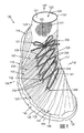
履物製品は、布地構成要素を含む。アッパーの布地構成要素は、布地要素および伸張性要素を含む。伸張性要素は、アッパーの第1の側部に配置される第1のセグメントを画定する。伸張性要素の第1のセグメントは、固定具を、アッパーの第1の側部の布地要素に取り付けるように構成されている。伸張性要素は、第2の側部のアッパーの下方部の近傍に配置される第2のセグメントをさらに含む。第2のセグメントは、第2の側部のアッパーの下方部に対して固定される。伸張性要素は、第1のセグメントから、かかと領域を横切って、第2のセグメントまで連続的に延びている中間セグメントをさらに含む。【選択図】図1The footwear product includes a fabric component. The upper fabric component includes a fabric element and an extensible element. The extensible element defines a first segment disposed on the first side of the upper. The first segment of the extensible element is configured to attach the fastener to the fabric element on the first side of the upper. The extensible element further includes a second segment disposed proximate a lower portion of the second side upper. The second segment is secured to the lower portion of the second side upper. The extensible element further includes an intermediate segment that extends continuously from the first segment across the heel region to the second segment. [Selection] Figure 1
Description
本発明は、一般に、履物製品に関し、具体的には、布地構成要素を有する製品に関する。 The present invention relates generally to footwear products, and specifically to products having fabric components.
従来の履物製品は、一般的に、アッパーおよびソール構造という2つの主要な要素を含んでいる。アッパーは、ソール構造に固定されて、足を快適にかつ安定して受け入れるために、履物の内部に空洞を形成している。ソール構造は、それによってアッパーと地面との間に位置するように、アッパーの下側区域に固定されている。たとえば、運動用の履物では、ソール構造は、ミッドソールとアウトソールとを含んでいてもよい。ミッドソールは、多くの場合、地面の反力を弱めて、歩くとき、走るとき、および他の歩行活動中に足および脚にかかる応力を低減するポリマー発泡材料を含んでいる。くわえて、ミッドソールは、力をさらに弱め、安定性を高め、または足の動きに影響を与える流体充填チャンバ、プレート、モデレータ、または他の要素を含んでいてもよい。アウトソールは、ミッドソールの下面に固定されて、ゴム等の耐久性のある耐摩耗性材料から形成されたソール構造の地面係止部を形成している。また、ソール構造は、履物の快適性を高めるために、空洞内に配置され、足の下面に近接する中敷きも含んでいてもよい。 Conventional footwear products generally include two main elements: an upper and a sole structure. The upper is fixed to the sole structure and forms a cavity inside the footwear to receive the foot comfortably and stably. The sole structure is secured to the lower area of the upper so that it lies between the upper and the ground. For example, in athletic footwear, the sole structure may include a midsole and an outsole. The midsole often includes a polymeric foam material that reduces ground reaction forces and reduces stress on the feet and legs when walking, running, and during other walking activities. In addition, the midsole may include fluid-filled chambers, plates, moderators, or other elements that further reduce forces, increase stability, or affect foot movement. The outsole is fixed to the lower surface of the midsole and forms a ground engaging portion of a sole structure formed of a durable wear-resistant material such as rubber. The sole structure may also include an insole disposed within the cavity and proximate to the lower surface of the foot to enhance the comfort of the footwear.
アッパーは、大略的に、足の甲周りおよびつま先区域の上に、足の内側側部および外側側部に沿って、足の下に、さらに足のかかと区域の周りに延びている。バスケットボール用履物およびブーツなどいくつかの履物製品では、アッパーは上方に、足首の周りに延びて、足首に支持または保護を与えてもよい。アッパーの内部の空洞へのアクセスは一般に、履物のかかと領域にある足首開口部によって提供される。 The upper generally extends around the instep and toe area, along the inside and outside sides of the foot, below the foot and around the heel area of the foot. In some footwear products, such as basketball footwear and boots, the upper may extend upward and around the ankle to provide support or protection to the ankle. Access to the cavity inside the upper is generally provided by an ankle opening in the heel area of the footwear.
さまざまな材料要素が、従来、アッパーを製造する際に利用されている。たとえば、運動用の履物では、アッパーは、さまざまな接合材料要素を含む複数の層を有していてもよい。例として、それらの材料要素は、耐伸張性、耐摩耗性、柔軟性、通気性、圧縮性、快適性および速乾性を、アッパーの異なる区域に付与するように選択してもよい。アッパーの異なる区域に異なる特性を付与するために、材料要素は、所望の形状に切断してから、通常は、縫製または接着剤で互いに接合することが多い。また、材料要素は、同じ区域に複数の特性を付与するために、層状構成で接合されることが多い。アッパーに組み込まれる材料要素の数および種類が増えるにつれ、材料要素の輸送、保管、切断および接合に関連する時間および費用も増加する可能性がある。切断および縫製プロセスから出る廃材も、アッパーに組み込まれる材料要素の数および種類が増えるにつれて、さらに多く蓄積する。さらに、アッパーの材料要素の数が多くなるほど、種類および数が少ない材料要素から形成されたアッパーよりもリサイクルが難しくなることがある。そのため、アッパーに利用する材料要素の数を減らすことにより、アッパーの製造効率およびリサイクル性を高めながら、廃棄物を少なくすることができる。 Various material elements are conventionally utilized in manufacturing uppers. For example, in athletic footwear, the upper may have multiple layers that include various bonding material elements. By way of example, the material elements may be selected to impart stretch resistance, abrasion resistance, flexibility, breathability, compressibility, comfort and quick drying to different areas of the upper. In order to impart different properties to different areas of the upper, the material elements are often cut into the desired shape and then joined together, usually with sewing or adhesive. Also, the material elements are often joined in a layered configuration to impart multiple properties to the same area. As the number and type of material elements incorporated into the upper increases, the time and costs associated with transporting, storing, cutting and joining the material elements can also increase. More waste material from the cutting and sewing process accumulates as the number and type of material elements incorporated into the upper increases. In addition, the greater the number of material elements in the upper, the more difficult it may be to recycle than an upper formed from fewer and fewer material elements. Therefore, by reducing the number of material elements used for the upper, waste can be reduced while improving the manufacturing efficiency and recyclability of the upper.
着用者の足を受け入れるように構成され、および固定具を支持するように構成されている履物製品が開示されている。固定具は、履物製品の足に対するフィット感を選択的に変えるように構成されている。履物製品は、ソール構造と、ソール構造に取り付けられている下方部を有するアッパーとを含む。アッパーは、かかと領域と、第1の側部と、第2の側部とをさらに含む。アッパーは、アッパーのかかと領域と、第1の側部と、第2の側部とを少なくとも部分的に画定する布地要素を含む布地構成要素をさらに含む。布地構成要素は、布地要素に取り付けられている伸張性要素をさらに含む。伸張性要素は、アッパーの第1の側部に設けられた第1のセグメントを画定する。伸張性要素の第1のセグメントは、アッパーの第1の側部で、固定具を布地要素に取り付けるように構成されている。伸張性要素は、第2の側部において、アッパーの下方部の近傍に配置されている第2のセグメントをさらに含む。第2のセグメントは、第2の側部において、アッパーの下方部に対して固定されている。伸張性要素は、第1のセグメントから、かかと領域を横切って、第2のセグメントまで連続的に延びている中間セグメントをさらに含んでいる。伸張性要素は、アッパーの第1の側部に加えられた力の少なくとも一部を、かかと領域を横切って、第2の側部のアッパーの下方部まで伝達するように構成されている。 An article of footwear configured to receive a wearer's foot and configured to support a fastener is disclosed. The fixture is configured to selectively change the fit of the footwear product to the foot. The footwear product includes a sole structure and an upper having a lower portion attached to the sole structure. The upper further includes a heel region, a first side, and a second side. The upper further includes a fabric component that includes a fabric element that at least partially defines a heel region, a first side, and a second side of the upper. The fabric component further includes an extensible element attached to the fabric element. The extensible element defines a first segment provided on the first side of the upper. The first segment of the extensible element is configured to attach the fastener to the fabric element at the first side of the upper. The extensible element further includes a second segment disposed on the second side, proximate to the lower portion of the upper. The second segment is fixed to the lower portion of the upper on the second side. The extensible element further includes an intermediate segment that extends continuously from the first segment across the heel region to the second segment. The extensible element is configured to transmit at least a portion of the force applied to the first side of the upper across the heel region to the lower portion of the second side upper.
また、着用者の足を受け入れるように構成され、および固定具を支持するように構成されている履物製品も開示されている。固定具は、履物製品の足に対するフィット感を選択的に変えるように構成されている。履物製品は、ソール構造と、足を受け入れるように構成された空洞を画定するアッパーとを含む。アッパーは、ソール構造に取り付けられた下方部を含む。アッパーは、かかと領域と、第1の側部と、第2の側部とを含む。アッパーは、一体ニット構造で形成されたニット構成要素をさらに含む。アッパーは、足の空洞内への通過を実行できるように構成された開口部を画定する。アッパーは、第1の側部と第2の側部との間に配置されるスロートをさらに含む。スロートは、開口部から延びている。アッパーのニット構成要素は、アッパーのかかと領域と、第1の側部と、第2の側部とを少なくとも部分的に画定するニット要素を含んでいる。また、ニット構成要素は、ニット要素とともに一体ニット構造で形成されている第1の伸張性要素も含む。第1の伸張性要素は、第1の側部のスロートから、かかと領域を横切って、第2の側部の下方部まで連続的に延びている。さらに、ニット構成要素は、ニット要素とともに一体ニット構造で形成されている第2の伸張性要素を含む。第2の伸張性要素は、第2の側部のスロートから、第2の側部の下方部まで連続的に延びている。第1の伸張性要素は、第1の側部のスロートに配置され、および第1の側部で固定具を収容するように構成されている少なくとも1つの第1のセグメントを画定する。第2の伸張性要素は、第2の側部のスロートに配置され、および第2の側部で固定具を収容するように構成されている少なくとも1つの第2のセグメントを画定する。 Also disclosed is an article of footwear that is configured to receive a wearer's foot and that is configured to support a fastener. The fixture is configured to selectively change the fit of the footwear product to the foot. The footwear product includes a sole structure and an upper that defines a cavity configured to receive a foot. The upper includes a lower portion attached to the sole structure. The upper includes a heel region, a first side, and a second side. The upper further includes a knit component formed in a unitary knit structure. The upper defines an opening configured to allow passage through the foot cavity. The upper further includes a throat disposed between the first side and the second side. The throat extends from the opening. The upper knit component includes a knit element that at least partially defines an upper heel region, a first side, and a second side. The knit component also includes a first extensible element that is formed in a unitary knit structure with the knit element. The first extensible element extends continuously from the throat of the first side across the heel region to the lower portion of the second side. In addition, the knit component includes a second extensible element that is formed in a unitary knit structure with the knit element. The second extensible element extends continuously from the throat of the second side to the lower part of the second side. The first extensible element is disposed in the throat of the first side and defines at least one first segment configured to receive a fastener on the first side. The second extensible element is disposed in the throat of the second side and defines at least one second segment configured to receive a fastener on the second side.
また、ニット構成要素は、履物製品用アッパーを画定するように構成されているニット構成要素が開示されている。アッパーは、足先領域と、かかと領域と、足先領域とかかと領域との間に延びている第1の側部と、足先領域とかかと領域との間に延びている第2の側部とを含む。ニット構成要素は、ニット要素と、ニット要素とともに一体ニット構造で形成された伸張性ストランドとを含んでいる。ニット要素は、前面および裏面を含む。ニット要素は、第1の端部および第2の端部を含む。ニット要素は、第1の端部と第2の端部との間に大略的に延びているチューブ状リブ構造をさらに含む。チューブ状リブ構造は、第2の端部の近傍に設けられた開端部を含む。伸張性要素は、チューブ状リブ構造内に収容される第1のセグメントを含む。伸張性要素は、第1のセグメントから延び、および開端部から出て延びている第2のセグメントをさらに含む。伸張性要素は、第1のセグメントから延び、前面からニット要素を出て、前面を通ってニット要素内に戻って延びている第3のセグメントをさらに含む。ニット要素の第1の端部は、アッパーの第2の側部で固定されるように構成されている。ニット要素の第2の端部は、アッパーの第2の側部で固定されるように構成されている。第1のセグメントは、第1の側部からチューブ状リブ構造を通って、かかと領域を横切って、アッパーの第2の側部まで延びるように構成されている。第2のセグメントは、アッパーの第2の側部で、ニット要素に対して固定されるように構成されている。第1のセグメントは、アッパーの第1の側部に配置されるように構成されている。 Also disclosed is a knit component that is configured to define an upper for a footwear product. The upper includes a toe region, a heel region, a first side portion extending between the toe region and the heel region, and a second side portion extending between the toe region and the heel region. Including. The knitted component includes a knitted element and an extensible strand formed in a unitary knitted structure with the knitted element. The knit element includes a front surface and a back surface. The knitted element includes a first end and a second end. The knitted element further includes a tubular rib structure extending generally between the first end and the second end. The tubular rib structure includes an open end provided in the vicinity of the second end. The extensible element includes a first segment housed within the tubular rib structure. The extensible element further includes a second segment extending from the first segment and extending out of the open end. The extensible element further includes a third segment extending from the first segment, exiting the knit element from the front surface, and extending back through the front surface into the knit element. The first end of the knitted element is configured to be secured at the second side of the upper. The second end of the knitted element is configured to be secured at the second side of the upper. The first segment is configured to extend from the first side through the tubular rib structure and across the heel region to the second side of the upper. The second segment is configured to be fixed relative to the knit element at the second side of the upper. The first segment is configured to be disposed on the first side of the upper.
さらに、履物製品用アッパーを形成する方法が開示されている。その方法は、布地要素および伸張性要素を含む布地構成要素を形成することを含む。布地要素は、前面および裏面と、第1の端部および第2の端部と、第1の端部と第2の端部との間に大略的に延びているチューブ状リブ構造とを含む。その方法は、伸張性要素の第1のセグメントが、チューブ状リブ構造内に収容されるように伸張性要素を通すことをさらに含む。さらに、その方法は、伸張性要素の第2のセグメントが、第1のセグメントから、チューブ状リブ構造の開端部を出て延びるように伸張性要素を通すことを含む。また、その方法は、伸張性要素の第3のセグメントが、第1のセグメントから延び、前面から布地要素を出て、前面を通って布地要素内に戻って延びるように伸張性要素を通すことを含む。さらに、その方法は、アッパーの第1の側部と、足先領域と、第2の側部と、かかと領域とを画定するように布地構成要素を組立てることを含む。布地構成要素を組立てることは、布地構成要素を、第2の側部から、足先領域を横切って、第1の側部を横切って、かかと領域を横切って、第2の側部に戻って巻くことを含む。また、布地構成要素を組立てることは、布地要素の第1の端部を、アッパーの第2の側部に設けることと、布地要素の第2の端部を、アッパーの第2の側部に設けることとを含む。さらに、布地構成要素を組立てることは、第1のセグメントをチューブ状リブ構造を通して、第1の側部から、かかと領域を横切って、アッパーの第2の側部まで延ばすことを含む。さらに、布地構成要素を組立てることは、第2のセグメントを、アッパーの第2の側部の布地要素に対して固定することを含む。さらにまた、布地構成要素を組立てることは、アッパーの第1の側部に第1のセグメントを設けることを含む。 Furthermore, a method for forming an upper for a footwear product is disclosed. The method includes forming a fabric component that includes a fabric element and an extensible element. The fabric element includes a front surface and a back surface, a first end and a second end, and a tubular rib structure extending generally between the first end and the second end. . The method further includes passing the extensible element such that the first segment of the extensible element is received within the tubular rib structure. Further, the method includes passing the extensible element such that the second segment of the extensible element extends from the first segment out of the open end of the tubular rib structure. The method also includes passing the extensible element such that the third segment of the extensible element extends from the first segment, exits the fabric element from the front surface, passes through the front surface and back into the fabric element. including. Further, the method includes assembling the fabric component to define a first side of the upper, a toe region, a second side, and a heel region. Assembling the fabric component returns the fabric component from the second side, across the toe region, across the first side, across the heel region, back to the second side. Including winding. Also, assembling the fabric component includes providing a first end of the fabric element on the second side of the upper and a second end of the fabric element on the second side of the upper. Providing. Further, assembling the fabric component includes extending the first segment through the tubular rib structure from the first side across the heel region to the second side of the upper. Further, assembling the fabric component includes securing the second segment to the fabric element on the second side of the upper. Still further, assembling the fabric component includes providing a first segment on a first side of the upper.
本実施形態の他のシステム、方法、特徴および利点は、以下の図面および詳細な説明を検討すれば、当業者には明らかであるか、または明らかになるであろう。そのようなすべての追加的なシステム、方法、特徴および利点が、この説明およびこの概要の範囲内に含まれること、本実施形態の範囲内に含まれること、および以下の請求項によって保護されることが意図されている。 Other systems, methods, features and advantages of this embodiment will be or will be apparent to those of ordinary skill in the art upon review of the following drawings and detailed description. All such additional systems, methods, features and advantages are included within the scope of this description and this summary, are included within the scope of this embodiment, and are protected by the following claims. Is intended.
本開示は、以下の図面および説明を参照することで、より良く理解することができる。図面の構成要素は、必ずしも縮尺どおりではなく、代わりに、本開示の原理を説明するにあたって強調を施している。さらに、図面中で、同様の符号は、異なる図にわたって、類似の部材を示すものとする。 The present disclosure can be better understood with reference to the following drawings and description. The components of the drawings are not necessarily to scale, emphasis instead being placed upon describing the principles of the present disclosure. Moreover, in the drawings, like numerals indicate like members throughout the different views.
以下の説明および添付図面は、履物製品に関するさまざまな概念を開示している。履物は、布地構成要素によって少なくとも部分的に画定されているアッパーを含むことができる。布地構成要素は、着用者の足に対して有利なフィット感および柔軟性をもたらすことができる。たとえば、いくつかの実施形態において、布地構成要素は、着用者の足に適合させることができ、および着用者の足の動きを支持するように曲がることができる。 The following description and the accompanying drawings disclose various concepts relating to footwear products. The footwear can include an upper that is at least partially defined by a fabric component. The fabric component can provide an advantageous fit and flexibility to the wearer's foot. For example, in some embodiments, the fabric component can be adapted to the wearer's foot and bend to support the movement of the wearer's foot.
また、布地構成要素は、着用者の足を支持するために、布地構成要素の全域に力を伝える伸張性要素を含むことができる。また、伸張性要素は、アッパーの曲げおよび/または伸張に影響を与えることもできる。たとえば、いくつかの実施形態において、伸張性要素は、布地構成要素の過剰な曲げおよび/または伸張を制限することができる。 The fabric component can also include extensible elements that transmit force across the fabric component to support the wearer's foot. The stretchable element can also affect the bending and / or stretching of the upper. For example, in some embodiments, the extensible element can limit excessive bending and / or stretching of the fabric component.
さらに、いくつかの実施形態において、アッパーの一方の側に加えられた力は、アッパーの反対側に伝達および/または分散させることができる。いくつかの実施形態において、このことは、ランニング、ジャンプ、方向変換時に、または、他の歩行活動中に、アッパーを大略的に内側方向に曲げさせて、足を圧迫させることができる。したがって、アッパーは、着用者の足に確実にフィットさせることができ、および幅広い活動を支援することができる。 Further, in some embodiments, the force applied to one side of the upper can be transmitted and / or distributed to the opposite side of the upper. In some embodiments, this can cause the upper to bend in a generally inward direction during running, jumping, turning, or during other ambulatory activities to compress the foot. Thus, the upper can reliably fit the wearer's foot and can support a wide range of activities.
履物製品の全体的説明
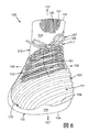
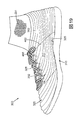
最初に、図1〜図6を参照すると、例示的な実施形態による履物製品100が図示されている。一般に、履物100は、ソール構造110およびアッパー120を含むことができる。アッパー120は、着用者の足を受け入れて、履物100を着用者の足に対して締め付けることができる。ソール構造110は、アッパー120の下に延びて、着用者を支持することができる。
General Description of Footwear Products Referring initially to FIGS. 1-6, an article of
参照のために、履物100は、3つの大略的領域、すなわち、足先領域111と、中足領域112と、かかと領域114とに分けてもよい。足先領域111は、つま先と、中足骨と指骨を接続する関節とを含む、着用者の足の前方部に相当する履物100の部分を大略的に含むことができる。中足領域112は、アーチ区域を含む、着用者の足の中間部に相当する履物100の部分を大略的に含むことができる。かかと領域114は、かかとおよび踵骨を含む、着用者の足の後方部に相当する履物100の部分を大略的に含むことができる。
For reference,
履物100は、外側側部115および内側側部117も含むことができる。いくつかの実施形態において、外側側部115および内側側部117は、足先領域111と、中足領域112と、かかと領域114とを通って延びることができる。外側側部115および内側側部117は、履物100の両側部に対応させることができる。より具体的には、外側側部115は、着用者の足の外側区域(すなわち、他方の足から離れて対向する面)に対応させることができ、内側側部117は、着用者の足の内側区域(すなわち、他方の足に向かって対向する面)に対応させることができる。
足先領域111、中足領域112、かかと領域114、外側側部115および内側側部117は、履物100の正確な区域を画定することは意図されていない。むしろ、足先領域111、中足領域112、かかと領域114、外側側部115および内側側部117は、以下の説明において役立つように、履物100の大略的区域を表すことが意図されている。
The
また、履物100は、さまざまな方向に沿って延びることもできる。たとえば、図1〜図6に図示されているように、履物100は、長手方向105、横方向106および垂直方向107に沿って延びることができる。長手方向105は、大略的に、かかと領域114と足先領域111との間に延びることができる。横方向106は、大略的に、外側側部115と内側側部117との間に延びることができる。また、垂直方向107は、大略的に、アッパー120とソール構造110との間に延びることができる。長手方向軸105、横方向106および垂直方向107は、履物100の異なる形状構成の相対的位置を説明するために、および以下の説明において役立つように、参照目的で以下の説明に含まれていることは正しく認識されるであろう。
The
次に、ソール構造110の実施形態について、図1〜図4および図6を参照して説明する。ソール構造110は、アッパー120に取り付けることができ、および履物100が着用された場合に、着用者の足と地面の間に延びることができる。いくつかの実施形態において、ソール構造110は、均一なワンピース部材とすることができる。あるいは、いくつかの実施形態において、ソール構造110は、アウトソールおよびミッドソール等の複数の構成要素を含むことができる。
Next, an embodiment of the
また、ソール構造110は、地面係止面104を含むことができる。地面係止面104は、地面接触面と呼ぶこともできる。さらに、ソール構造110は、アッパー120に対向する上面108を含むことができる。言い換えると、上面108は、地面係止面104から反対方向に対向していてもよい。さらに、ソール構造110は、周辺側面109を含むことができる。いくつかの実施形態において、周辺側面109は、上面108と地面係止面104との間で、垂直方向107に延びることができる。場合によっては、周辺側面109は、かかと領域114、中足領域112および足先領域111のうちの1つ以上の少なくとも一部を通って延びることを含み、履物100の外側周辺部の周りに少なくとも部分的に延びることができる。また、いくつかの実施形態において、周辺側面109は、かかと領域114から内側側部117に沿って、足先領域111を横切って、外側側部115に沿って、かかと領域114に戻って連続的に延びることができる。さまざまな実施形態において、垂直方向107に沿った周辺側面109の高さは、変えてもよい。場合によっては、その高さは、周辺側面109の大部分に沿って、実質的に同様であってもよい。他の場合では、周辺側面109の部分は、かかと領域114、中足領域112または足先領域111のうちの1つ以上を通って延びている周辺側面109の異なる部分にわたって、より大きくまたはより小さくてもよい。
In addition, the
さらに、ソール構造110は、ソール構造110がそこでアッパー120に取り付けられる固定区域103を含むことができる。図示されているように、固定区域103は、周辺側面109の近傍の上面108で画定することができる。追加的な実施形態では、固定区域103は、周辺側面109に画定することができる。
Further, the
いくつかの実施形態において、ソール構造110は、ミッドソールおよびアウトソールを含むことができる。ミッドソールは、弾性圧縮可能な材料、流体充填ブラダー等を含むことができる。したがって、ミッドソールは、着用者の足の衝撃を和らげることができ、また、ランニング、ジャンプ等をしたときに、衝撃や他の力を弱めることができる。アウトソールは、ミッドソールに固定することができ、およびゴム等の耐摩耗材料を含むことができる。また、アウトソールは、地面係止面104のための踏面および他の静止摩擦強化形状構成も含むことができる。
In some embodiments, the
次に、図1〜図6を参照して、アッパー120の実施形態について説明する。図示されているように、アッパー120は、着用者の足を受け入れる空洞122を画定することができる。言い換えれば、アッパー120は、空洞122を画定する内側面121を画定することができ、また、アッパー120は、内側面121の反対側の方向に対向する外側面123を画定することができる。着用者の足が空洞122内に受け入れられると、アッパー120は、着用者の足を少なくとも部分的に包囲して密閉することができる。したがって、いくつかの実施形態において、アッパー120は、足先領域111、外側側部115、かかと領域114および内側側部117の周りに延びることができる。
Next, an embodiment of the upper 120 will be described with reference to FIGS. As shown, the upper 120 can define a
アッパー120は、ソール構造110に取り付けられる下方部125を追加的に含むことができる。したがって、アッパー125の下方部125は、ソール構造110の固定区域103に固定することができる。いくつかの実施形態において、アッパー120の下方部125は、アッパー120の下方周辺部に画定することができ、および着用者の足の周りに延びることができる。また、いくつかの実施形態において、アッパー120の下方部125は、内側側部117と外側側部115との間に、および/または着用者の足の下で、かかと領域114と足先領域111との間に延びることができる。
The upper 120 may additionally include a
アッパー120は、カラー124も含むことができる。カラー124は、足の空洞122からの出し入れの間に、着用者の足の通過を可能にするように構成されているカラー開口部126を含むことができる。
Upper 120 can also include a
アッパー120は、スロート128も含むことができる。スロート128は、カラー開口部126から足先領域111に向かって、スロート軸101に沿って延びることができる。スロート128は、足を覆って延びることができ、および第1の外側側部115と内側側部117との間に画定することができる。スロート128の寸法は、外側側部115と内側側部117との間の履物100の幅を変更するために変えることができる。したがって、スロート128は、履物製品100のフィット感および快適性に影響を与えることができる。
Upper 120 can also include a
図1〜図6の実施形態等のいくつかの実施形態においては、スロート128は、「閉じた」スロート128とすることができ、その場合、アッパー120は、外側側部115と内側側部117との間で実質的に連続し、および途切れていない。他の実施形態では、スロート128は、外側側部115と内側側部117との間にスロート開口部を含むことができる。これらの後者の実施形態では、履物100は、スロート開口部内に配置されているベロを含むことができる。たとえば、いくつかの実施形態では、ベロは、その前方端部において、足先領域111に取り付けることができ、また、ベロは、外側側部115および内側側部117から取り外すことができる。したがって、ベロは、スロート開口部を実質的に塞ぐことができる。
In some embodiments, such as the embodiment of FIGS. 1-6, the
履物100は、図1〜図6に示すように、固定具127を追加的に含むことができる。固定具127は、着用者が、履物100の寸法を調整するために用いることができる。たとえば、固定具127は、着用者が、履物100の周長または幅を選択的に変えるために用いることができる。したがって、固定具127は、履物100の着用者の足に対するフィット感を選択的に変えるように構成することができる。固定具127は、いずれかの適当なタイプとすることができ、および任意の適当な箇所で履物100に結合することができる。たとえば、図1〜図6に示すいくつかの実施形態において、固定具127は、外側側部115および内側側部117の両方に取り付けられる靴ひも129を含むことができる。他の実施形態では、固定具127は、ストラップ、バックル、フック、引きひも、スプールまたは他の何らかの装置を含むことができる。固定具127を緊張させることにより、外側側部115および内側側部117を互いに向けて引っ張って、履物100を着用者の足に対して締め付けることができる。したがって、履物100を、着用者の足にきつく締め付けることができる。固定具127の張力を下げることにより、履物100を弛めることができ、また、履物100を容易に履くことができ、または、履物を着用者の足から容易に取り外すことができる。
The
従来の多くの履物アッパーは、たとえば、縫製または接着によって接合される複数の材料要素から形成されている。対照的に、アッパー120の少なくとも一部は、ニット構成要素130等の布地構成要素によって形成および画定することができる。ニット構成要素130は、一体ニット構造で形成することができる。
Many conventional footwear uppers are formed from a plurality of material elements joined together, for example, by sewing or gluing. In contrast, at least a portion of upper 120 can be formed and defined by a fabric component, such as
他の実施形態では、アッパー120は、ニット構成要素130と同様ではあるが、異なる材料を用いて形成されている構造によって、少なくとも部分的に画定することができる。たとえば、アッパー120は、織物構造等の他の種類の布地構成要素によって画定することができる。さらなる実施形態では、アッパー120は、革、ポリマーまたは他の種類の材料等の非布地材料によって形成および画定することができる。さらに、アッパー120は、一緒に接合される2つ以上のピース(すなわち、非一体構造)から組み立てられる構造によって画定することができる。
In other embodiments, the upper 120 can be at least partially defined by a structure that is similar to the
いくつかの実施形態において、ニット構成要素130は、アッパー120内の空洞122の少なくとも一部を画定することができる。また、いくつかの実施形態では、ニット構成要素130は、外側面123の少なくとも一部を画定することができる。さらに、いくつかの実施形態では、ニット構成要素130は、アッパー120の内側面121の少なくとも一部を画定することができる。また、いくつかの実施形態では、ニット構成要素130は、アッパー120のかかと領域114、中足領域112、足先領域111、内側側部117および外側側部115のかなりの部分を画定することができる。したがって、いくつかの実施形態において、ニット構成要素130は、着用者の足を取り囲むことができる。また、いくつかの実施形態において、ニット構成要素130は、着用者の足を圧迫して、着用者の足に対して締め付けることができる。
In some embodiments, the
したがって、アッパー120は、比較的少数の材料要素で構成することができる。このことは、アッパー120の製造効率およびリサイクル性も向上させながら、廃棄物を減らすことができる。さらに、アッパー120のニット構成要素130は、より少数の縫い目または他の不連続部を組み込むことができる。このことは、履物100の製造効率をさらに向上させることができる。さらに、アッパー120の内側面121は、実質的に滑らかかつ均一にして、履物100の全体の快適性を高めることができる。
Accordingly, the upper 120 can be composed of a relatively small number of material elements. This can reduce waste while improving the manufacturing efficiency and recyclability of the upper 120. Further, the
既に述べたように、ニット構成要素130は、一体ニット構造で形成することができる。本願明細書および請求項において用いる場合、ニット構成要素(たとえば、ニット構成要素130、または、本願明細書に記載されている他のニット構成要素)は、編みプロセスによってワンピース要素として形成される場合、「一体ニット構造」で形成されると定義される。すなわち、編みプロセスは、かなりの追加の製造工程またはプロセスを要することなく、ニット構成要素130のさまざまな形状構成および構造を実質的に形成している。一体ニット構造は、ヤーンから成る1つ以上のコースを含む構造または要素、または、それらの構造または要素が、少なくとも1つのコースを共通して含むように(すなわち、共通ヤーンを共有する)、および/または構造または要素の各々の間に実質的に連続しているコースを含むように接合されている他のニット材料を有するニット構成要素を形成するのに用いることができる。この構成の場合、一体ニット構造から成るワンピース要素が形成される。
As already mentioned, the
ニット構成要素130の部分は、編みプロセスに続いて、互いに接合してもよいが(たとえば、ニット構成要素100の縁部は、一緒に接合される)、ニット構成要素130は、ワンピースニット要素として形成されているため、依然として、一体ニット構造で形成されている状態である。さらに、ニット構成要素130は、編みプロセスに続いて、他の要素(たとえば、締めひも、ロゴ、商標、注意書きや材料情報を記載した札、構造要素)が付け加えられた場合も、依然として一体ニット構造で形成された状態のままである。
The portions of the knitted
異なる実施形態では、一体ニット構造で形成されたニット構成要素130を製造するのに、限定するものではないが、たとえば、縦編みまたは横編みならびに丸編みプロセス、または、ニット構成要素を形成するのに適している他の何らかの編みプロセスを含む何らかの適当な編みプロセスを利用してもよい。ニット構成要素のさまざまな構成および一体ニット構造を伴うニット構成要素130を形成するための方法の実施例は、Duaに対する特許文献1およびDua等に対する特許文献2に開示されており、各々の開示は、参照によってその全体が本願明細書に組み込まれるものとする。また、ニット構成要素130は、本出願と同時に出願された“Article of Footwear Incorporating A Knitted Component With Inlaid Tensile Elements and Method of Assembly”というタイトルのAdrian Meirに対する米国仮出願特許第62/057,264号明細書に開示されている1つ以上の形状構成を含むこともでき、その開示は、参照によって、その全体が本願明細書に組み込まれるものとする。
In different embodiments, for example, but not limited to producing a
ニット構成要素130は、ニット要素131を大略的に含むことができる。また、ニット要素131は、「布地要素」と呼ぶこともできる。また、ニット構成要素130は、少なくとも1つの伸張性要素132を大略的に含むこともできる。ニット要素131および伸張性要素132は、一体ニット構造で形成することができる。
The
説明されているように、ニット要素131は、アッパー120の比較的大きな区域を画定することができる。いくつかの実施形態において、ニット要素131のニット構造は、有利な柔軟性、弾力性、弾性および伸張性をアッパーに与えることができる。したがって、ニット要素131およびアッパー120は、快適に着用することができる。また、ニット要素131は、快適性を損なうことなく、着用者の足が、アッパー120内で曲がりおよび動くことを可能にする。また、伸張性要素132は、所定の区域に対する支持性および強度を高めるように、それらの区域内のニット要素131を横切って通すことができる。さらに、伸張性要素132は、所定の方法で、ニット要素131の全域に力を伝達し、および/またはニット要素131の全域に力を分散させることができる。したがって、1つの区域で、ニット要素131に加えられた力は、ニット要素の全域で別の区域に伝達することができる。いくつかの実施形態において、このことは、ランニング、ジャンプ、方向転換または他の動きの間に、ニット要素131を、すなわちアッパー120を、追加的な支持性および快適性のために着用者の足に押し付けることができる。
As described, the
ニット要素の実施形態
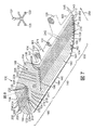
次に、ニット要素131について、例示的な実施形態に従って詳細に説明する。本開示のいくつかの実施形態によるニット要素131は、図7においては、分解された、実質的に平坦な位置で図示され、また図8〜図10には詳細に図示されている。ニット要素131は、図11〜図16には、履物製品100用のアッパー120に組付けられている過程で図示されている。図示されているように、いくつかの実施形態では、ニット要素131は、ニット構成要素130およびアッパー120の大部分を画定することができる。
Embodiment of Knit Element Next, the
図7に図示されているように分解されている場合、ニット要素131は、大略的にシート状にすることができ、およびさまざまな方向に沿って延びることができる。たとえば、図7には、参照のために、第1の方向133と、第2の方向135と、第3の方向137とが示されている。
When disassembled as illustrated in FIG. 7, the
ニット要素131は、大略的に、第1の端部134および第2の端部136を含むことができる。第1の端部134と第2の端部136は、大略的に第1の方向133において、互いに離間されている。また、ニット要素131は、上縁部138および底縁部140を含むことができる。上縁部138および底縁部140は、第1の端部134と第2の端部136との間に延びることができ、また、上縁部138および底縁部140は、大略的に第2の方向135において、互いに離間させることができる。
The
また、ニット要素131は、前面142および裏面144を含むことができる。前面142および裏面144は、第3の方向137に沿って互いに対向させることができる。また、ニット要素131の厚さ145は、大略的に第3の方向137において、前面142と裏面144との間で測ることができる。
The
また、ニット要素131は、さまざまな部分に細分化することもできる。たとえば、ニット要素131は、第1の部分146と、第2の部分148と、第3の部分150とを含むことができ、これらは、大略的に第1の方向133に沿って配置されている。それらの部分の各々は、説明されているように、アッパー120のそれぞれの区域を画定することができる。
The
図7に示すいくつかの実施形態において、第1の端部134および底縁部140の比較的大きな部分は、実質的に直線方向に延びることができる。具体的には、いくつかの実施形態において、第1の端部134は、第2の方向135に実質的に沿って延びることができ、また、底縁部140は、第1の方向133に実質的に沿って延びることができる。さらに、いくつかの実施形態において、第1の端部134と底縁部140との間の移行部139は、凸状湾曲部を有することができる。
In some embodiments shown in FIG. 7, the relatively large portions of the
また、いくつかの実施形態において、第2の端部136は、比較的高い程度の湾曲を呈することができる。たとえば、いくつかの実施形態において、第2の端部136は、凸状に湾曲させることができる。より具体的には、第2の端部136は、第1の移行部141と第2の移行部143との間に延びることができる。第1の移行部141は、第2の移行部143よりも(第1の方向133に対して)第1の端部134に近接して配置することができる。また、第2の端部136は、第1の移行部141から第2の移行部143へ凸状に曲げることができる。
Also, in some embodiments, the
さらに、いくつかの実施形態において、上縁部138は、不均一にすることができ、および/または湾曲させることができる。たとえば、上縁部138に近接するニット要素131の領域は、1つ以上の突出部を含むことができる。また、上縁部138に近接するニット要素131の領域は、1つ以上の切り欠き、凹部または他の開口部を含むことができる。具体的には、図7に図示されているように、ニット要素131は、第1の端部134に近接して配置されている第1の突出部154を含むことができる。いくつかの実施形態において、第1の突出部154は、形状を大略的に三角形にすることができる。また、上縁部138は、第2の端部136に近接して配置されている第2の突出部155を含むことができる。いくつかの実施形態において、第2の突出部155は、形状を大略的に長方形にすることができる。さらに、上縁部138は、第1の突出部154と第2の突出部155との間に配置されている第3の突出部156を含むことができる。いくつかの実施形態において、第3の突出部156は、形状を大略的に三角形にすることができる。また、上縁部138は、第1の突出部154と第3の突出部156との間に配置されている切り欠き157を画定することができる。さらに、上縁部138は、第2の突出部155と第3の突出部156との間に延びている凹状湾曲部161を含むことができる。また、上縁部138は、実質的に直線状の部分163を含むことができ、その部分は、第2の突出部155と第2の端部136との間で、大略的に第1の方向133に沿って延びている。
Further, in some embodiments, the
いくつかの実施形態において、ニット要素131の前面142および/または裏面144は、実質的に平坦にすることができる。他の実施形態では、前面142および/または裏面144は、波状部、バンプ、リブ、隆起区域または凹状区域を含むことができる。
In some embodiments, the
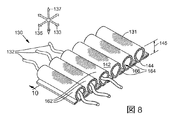
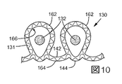
たとえば、図7〜図10に図示されているように、ニット要素131は、複数のチューブ状リブ構造162および複数のウェブ164を含むことができる。いくつかの実施形態において、ウェブ164は、チューブ状リブ構造162のそれぞれのペアの間に配置することができる。たとえば、図8〜図10に図示されているように、各ウェブ164は、チューブ状リブ構造162のそれぞれのペアに一緒に取り付けることができる。チューブ状リブ構造162におけるニット要素131の厚さ145は、ウェブ164におけるニット要素131の厚さ145よりも大きくすることができる。いくつかの実施形態において、ニット要素131の大部分は、それぞれのウェブ164によって分離されているチューブ状リブ構造162を含むことができる。いくつかの実施形態では、チューブ状リブ構造162とウェブ164は、ニット要素131の全域で交互に配置してもよい。すなわち、ウェブ164は、チューブ状リブ構造162の隣接するペアの間に配置してもよい。したがって、ニット要素131は、前面142および/または裏面144において、波状、波紋状、または不均一にすることができる。たとえば、図8〜図10に図示されているように、ウェブ164は、前面142よりも裏面144に近接してチューブ状リブ構造162に取り付けることができる。したがって、裏面144は、前面142よりも滑らかにすることができる。
For example, as illustrated in FIGS. 7-10, the
また、いくつかの実施形態において、1つ以上のチューブ状リブ構造162は、経路166を画定するように中空にすることができる。いくつかの実施形態では、経路166は、それぞれのチューブ状リブ構造162の長さの大部分に沿って延びることができる。
Also, in some embodiments, one or more
経路166は、何らかの適当な断面形状を有することができる。たとえば、図8〜図10に図示されているように、いくつかの実施形態において、経路166は、長円形または偏心の断面形状を有することができる。追加的な実施形態では、経路166は、実質的に円形、卵形または丸みを帯びた形状を有することができる。
The
チューブ状リブ構造162は、ニット要素131の全域で、任意の適当な方向に通すことができる。さらに、チューブ状リブ構造162は、ニット要素131の任意の適当な位置に含めることができる。たとえば、図7に示すいくつかの実施形態において、チューブ状リブ構造162は、大略的に第1の方向133において長手方向に延びることができる。また、いくつかの実施形態において、1つ以上のチューブ状リブ構造162は、ニット要素の第1の端部134と第2の端部136との間で連続的に延びることができる。したがって、チューブ状リブ構造162は、図7の実施形態に示すように、第1の部分146、第2の部分148および第3の部分150にわたって連続的に延びることができる。他のチューブ状リブ構造162は、第1の突出部154を横切って延びることができる。
The
また、チューブ状リブ構造162は、1つ以上の開口部を含むことができる。たとえば、図7に図示されているように、チューブ状リブ構造162は、第1の開端部190および第2の開端部192を含むことができる。第1の開端部190および第2の開端部192は、それぞれのチューブ状リブ構造162の両端部に設けることができる。たとえば、いくつかの実施形態では、第1の開端部190は、ニット要素131の第1の端部134に近接して設けることができ、また、第2の開端部192は、ニット要素131の第2の端部136に近接して設けることができる。また、チューブ状リブ構造162は、第1の開端部190と第2の開端部192との間に配置されている1つ以上の開口部を含むことができる。たとえば、図7に図示されているように、チューブ状リブ構造162は、第1の中間開口部194および第2の中間開口部196を含むことができる。いくつかの実施形態において、第1および/または第2の中間開口部194,196は、ニット要素131の前面142を通って延びているスルーホールとすることができる。また、第1および/または第2の中間開口部194,196は、大略的に第1の部分146内に配置することができる。第1および第2の中間開口部194,196は、第1の方向133において、互いに離間させることができる。さらに、第1の中間開口部194は、第2の中間開口部196よりも第1の端部134に近接して配置することができる。
The
また、いくつかの実施形態において、ニット要素131は、チューブ状リブ構造162を含む1つの区域と、含んでいない別の区域とを含むことができる。たとえば、図7に図示されているように、波状区域169と、実質的に滑らかな区域171との間に、境界167を画定することができる。波状区域169は、チューブ状リブ構造162と、接続ウェブ164とを含むことができる。滑らかな区域171は、実質的に平坦におよびシート状にすることができる。また、いくつかの実施形態において、境界167は、第1の突出部154に近接して、第2の端部136と上縁部138との間に延びることができる。いくつかの実施形態において、境界167のかなりの部分は、第1の方向133に実質的に平行に延びることができる。また、いくつかの実施形態において、波状区域169は、境界167と、第1の端部134と、底縁部140と、第2の端部136との間に画定することができ、それに対して、滑らかな区域171は、境界167と、上縁部138と、第2の端部136との間に画定することができる。
Also, in some embodiments, the
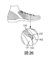
いくつかの実施形態において、ニット要素131の1つ以上の区域は、柔軟に、弾性的に、弾力的におよび伸張可能にすることができる。たとえば、図9に図示されているように、ニット要素131の典型的な区域は、実線で伸張していない位置に、および破線で伸張した位置に図示されている。いくつかの実施形態において、伸張していない位置は、「第1の位置」または「ニュートラル位置」と呼ぶこともできる。伸張した位置は、「第2の位置」と呼ぶこともできる。第1の位置では、ニット要素131の典型的な区域は、第1の長さ168を有することができる。第2の位置では、ニット要素131の典型的な区域は、第1の長さ168よりも大きい第2の長さ170を有することができる。いくつかの実施形態において、矢印172で表す伸張力は、たとえば、第2の方向135において、第1の長さ168と第2の長さ170との間でニット要素131を伸張させるために印加することができる。いくつかの実施形態では、伸張力が低下すると、ニット要素131の弾性は、ニット要素131を第1の位置へ戻すことができる。
In some embodiments, one or more areas of the
いくつかの実施形態において、ニット要素131の伸張性および弾性は、ニット要素131のニット構造に少なくとも部分的に依存する可能性がある。追加的な実施形態では、伸張性および弾性は、ニット要素131を形成するのに使用されるヤーンの弾性および伸張性に少なくとも部分的に依存する可能性がある。たとえば、ニット要素131の1つ以上のヤーンは、エラステインまたは他の弾性的で伸張可能な材料から形成することができる。したがって、いくつかの実施形態では、ニット要素131の少なくともいくつかのヤーンは、第1の長さから第2の長さまで、長さを弾性的に伸張させることができ、第2の長さは、第1の長さよりも少なくとも20%長い。伸張力が取り除かれると、ニット要素131のヤーンは、その伸張していないニュートラルな長さに戻ることができる。
In some embodiments, the extensibility and elasticity of the
また、いくつかの実施形態では、ニット要素131のいくつかの部分は、他の部分よりも、より弾性的にすることができる。たとえば、いくつかの実施形態において、ニット要素131のウェブ164は、チューブ状リブ構造162よりも弾性的にすることができる。さらに、いくつかの実施形態では、ニット要素131の滑らかな区域171は、ニット要素131の波状区域169よりも弾性的にすることができる。
Also, in some embodiments, some portions of the
アッパー120は、いくつかの点でニット要素131と同様である他の構造を含むことができるが、それらの構造は、他の点で異ならせることができることは正しく認識されるであろう。たとえば、アッパー120は、トンネル、チューブ、または経路166と同様の他の中空経路を画定する非ニット構造を含むことができる。さらに、アッパー120は、トンネル、チューブまたは他の中空経路を画定する複数の部材から組み立てられた構造(すなわち、非一体構造)を含むことができる。また、いくつかの実施形態では、アッパー120は、2つの重なっている層の間に延びている横方向のヤーンによって取り付けられているそれらの2つの層を有する、いわゆる「スペーサーニット」布地によって、少なくとも部分的に画定することができる。これらの実施形態では、経路は、2つの重なっているニット層の間に、および別々の横方向のヤーンの間に画定することができる。
It will be appreciated that the upper 120 may include other structures that are similar in some respects to the
伸張性要素の実施形態
次に、図7〜図10を参照して、伸張性要素132の実施形態について説明する。いくつかの実施形態において、ニット構成要素130は、複数の伸張性要素132を含むことができる。伸張性要素132は、任意の適当な区域のニット構成要素130上に配置することができることは正しく認識されるであろう。ニット構成要素130がアッパー120に組付けられた場合、たとえば、1つ以上の伸張性要素132は、大略的に外側側部115と内側側部117との間に延びることができる。したがって、いくつかの実施形態において、伸張性要素132は、着用者の足の周りに延びることができ、および伸張性要素132は、着用者の足を圧迫することができる。
Embodiments of Stretchable Elements Next, embodiments of the
伸張性要素132は、たとえば、ストランド、ヤーン、ケーブル、コード、繊維(たとえば、単繊維)、糸、ロープ、ウェビングまたはチェーンのうちのいずれか適当な種類で構成することができる。ニット要素131のヤーンと比較して、伸張性要素132の厚さは、より大きくてもよい。伸張性要素132の断面形状は、丸みを帯びていてもよいが、三角形、四角形、長方形、楕円形または不規則な形状を用いてもよい。また、伸張性要素132を形成している材料は、ニット要素131のヤーンのための材料のうちのいずれか、たとえば、綿、エラステイン、ポリエステル、レーヨン、ウールおよびナイロンを含んでいてもよい。上述したように、伸張性要素132は、ニット要素131よりも大きな耐伸張性を呈してもよい。したがって、伸張性要素132のための適当な材料は、ガラス、アラミド(たとえば、パラアラミドおよびメタアラミド)、超高分子量ポリエチレンおよび液晶ポリマーを含む、高引張強度用途に用いられるさまざまなエンジニアリングフィラメントを含んでいてもよい。別の実施例では、編んだポリエステル糸を伸張性要素132として利用してもよい。
The
ニット構成要素130の伸張性要素132および他の部分は、2008年12月18日に出願され、および2010年6月24日に特許文献3として公開された“Article of Footwear Having An Upper Incorporating A Knitted Component”というタイトルの、Dua等に対する共同所有の米国特許出願第12/338,726号明細書、2011年3月15日に出願され、および2012年9月20日に特許文献4として公開された“Article of Footwear Incorporating A Knitted Component”というタイトルの、Huffa等に対する米国特許出願第13/048,514号明細書、2013年2月28日に出願され、および2014年8月28日に特許文献5として公開された“Method of Knitting A Knitted Component with a Vertically Inlaid Tensile Element”というタイトルの、Podhajnyに対する米国特許出願第13/781,336号明細書のうちの1つ以上の教示を追加的に包含することができ、これらの明細書の各々は、参照により、その全体が本願明細書に組み込まれるものとする。
The
伸張性要素132は、何らかの適当な方法で、ニット要素131に取付けおよび組み込むことができる。たとえば、伸張性要素132は、要素131内に収容または格納して、伸張性要素132を要素131に取り付けることができる。より具体的には、いくつかの実施形態において、伸張性要素132は、要素131によって画定されたチューブ、トンネルまたは他の経路を通って延びることができる。伸張性要素132は、要素131の別々の層の間に配置することもでき、または、要素131によって別の方法で格納することもできる。
The
いくつかの実施形態において、伸張性要素132は、ニット要素131のコースまたはウェールに挿入することができる。図7〜図10の実施形態等の追加的な実施形態では、伸張性要素132は、経路166を通って、およびその経路に沿って延びることができる。言い換えると、ニット要素131のチューブ状リブ構造162内の少なくとも1つ以上の経路166は、伸張性要素132を収容することができる。追加的な実施形態、たとえば、ニット要素131が、スペーサーニット布地から形成されている実施形態では、伸張性要素132は、ニット要素131の異なる層の間に画定されている経路を通って延びることができる。
In some embodiments, the
さらに、上述したように、アッパー120は、実質的に非ニット構造によって、および/または一緒に接合されているピースから組み立てられた非一体構造によって画定することができる。それらの構造は、伸張性要素132を収容して、伸張性要素132を履物100に組み込む細長い中空のチューブまたは経路を画定することができることは正しく認識されるであろう。
Further, as described above, the upper 120 can be defined by a substantially non-knit structure and / or by a non-integral structure assembled from pieces joined together. It will be appreciated that these structures can accommodate the
伸張性要素132は、任意の数のチューブ状リブ構造162を通って延びることができる。たとえば、図7の実施形態に図示されているように、いくつかのチューブ状リブ構造162のみが、伸張性要素132を収容している。他の実施形態では、チューブ状リブ構造162の各々が伸張性要素132を収容している。さらに、いくつかの実施形態では、伸張性要素132は、ニット要素131上で互いに隣接しているチューブ状リブ構造162内に設けることができる。他の実施形態では、伸張性要素132は、1つのチューブ状リブ構造162内に存在することができ、また、伸張性要素132は、隣接するチューブ状リブ構造162には存在しない可能性がある。たとえば、伸張性要素132は、互い違いのまたは交互の構成を形成するように、他のすべてのチューブ状リブ構造162を通って延びることができる。他の実施形態では、伸張性要素132の存在は、規則的ではなくてもよい。たとえば、伸張性要素132を収容する2つ以上の隣接するチューブ状リブ構造162があってもよく、また、それらのチューブ状リブ構造162は、伸張性要素132を収容していない1つ以上のチューブ状リブ構造162に隣接させることができる。
The
いくつかの実施形態においては、伸張性要素132の単一の連続する区画が、複数の経路を通って延びることができる。他の実施形態では、個々の異なる伸張性要素132が、異なるチューブ状リブ構造162を通って延びることができる。
In some embodiments, a single continuous section of the
また、いくつかの実施形態では、伸張性要素132は、経路166の一部に沿って延びることができる。他の実施形態では、伸張性要素132は、実質的に経路166の全体に沿って延びることができる。
Also, in some embodiments, the
また、いくつかの実施形態において、伸張性要素132は、ニット要素131に対して、主に第1の方向133に沿って延びることができる。さらに、いくつかの実施形態では、伸張性要素132は、第2の方向135および/または第3の方向137に延びることができる。
Also, in some embodiments, the
さらに、いくつかの実施形態では、伸張性ストランド132の部分は、それぞれの経路166から出て延びることができ、およびニット要素131から露出させることができる。さらにまた、いくつかの実施形態では、伸張性要素132は、ニット要素131から出て延びることができ、およびニット要素131に再び入ることができる。したがって、伸張性要素132の出口と再入箇所との間に、ループまたは他の同様の形状構成を、伸張性要素132によって画定することができる。いくつかの実施形態では、伸張性要素132は、ループまたは同様の構造を画定するために、1つの経路166から出て延びて、異なる経路166に再び入ることができる。
Further, in some embodiments, portions of the
伸張性要素132は、所定の区域内のニット要素131を横切って通すことができる。伸張性要素132の張力は、伸張性要素132を介して、ニット要素131の1つの区域から別の区域へ伝達することができる。したがって、伸張性要素132は、所定の有利な方法で、ニット要素131の全域に力を分散させることができる。また、伸張性要素132を通しているため、伸張性要素132は、所定の方法で、ニット要素131の伸張および/または曲げを制限することができる。さらに、伸張性要素132は、靴ひも129または他の固定具127をニット要素131に取り付けるように機能するループまたは他の構造を画定するように通すことができる。
The
図7に図示されているように、ニット構成要素130は、第1の伸張性要素200を含むことができる。第1の伸張性要素200は、第1の端部202と、第2の端部204と、第1および第2の端部202,204の間に連続的に延びている中間部206とを含むことができる。また、ニット構成要素130は、第2の伸張性要素208を含むことができる。第2の伸張性要素208は、第1の端部210と、第2の端部212と、第1および第2の端部210,212の間に連続的に延びている中間部214とを含むことができる。説明されているように、第1の伸張性要素200および第2の伸張性要素208は、複数のセグメントに細分化することができる。
As illustrated in FIG. 7, the
いくつかの実施形態において、第1の伸張性要素200は、主に第1の部分146内で、ニット要素131を横切って延びることができる。第1の伸張性要素200の第1の端部202および第2の端部204は、ニット要素131の第1の端部134から出て延びることができ、および第1の端部134から露出させることができる。第1の伸張性要素200の中間部206は、第1のチューブ状リブ構造216、第2のチューブ状リブ構造218、第3のチューブ状リブ構造220、第4のチューブ状リブ構造224、第5のチューブ状リブ構造226、第6のチューブ状リブ構造228および第7のチューブ状リブ構造230の部分を通って連続的に延びることができる。より具体的には、第1の伸張性要素200は、第1のチューブ状リブ構造216の第1の開端部190に入って、第1の方向133に沿って、第1のチューブ状リブ構造216の第1の中間開口部194に向かって延びることができる。また、第1の伸張性要素200は、第1のチューブ状リブ構造216の第1の中間開口部194から出て、第1の中間開口部194に向かって折り返して、第1の中間開口部194に再び入ることができる。第1の伸張性要素200はさらに、第1のチューブ状リブ構造216に沿って戻って延び、第1の方向133に沿って、第1のチューブ状リブ構造216の第1の開端部190から出ることができる。また、第1の伸張性要素200は、上縁部138に向かって大略的に第2の方向135に延びて、第2のチューブ状リブ構造218を介してニット要素131に再び入ることができる。このルーティングパターンは、第1の伸張性要素200が、第2のチューブ状リブ構造218、第3のチューブ状リブ構造220、第4のチューブ状リブ構造224、第5のチューブ状リブ構造226、第6のチューブ状リブ構造228および第7のチューブ状リブ構造230を通って延びるように繰り返すことができる。いくつかの実施形態では、第7のチューブ状リブ構造230の第1の開端部190から出て延びることができる第1の伸張性要素200は、第2の端部204で終端することができる。
In some embodiments, the first
このように通すことにより、第1の伸張性要素200は、複数の第1の内側ループセグメント232を画定することができ、そこでは、ストランド200が中間開口部194に出入りしている。また、第1の伸張性要素200は、複数の第1の外側ループセグメント234を画定することができ、そこでは、ストランド200が、1つのチューブ状リブ構造162の開端部190から出て、別のチューブ状リブ構造162の開端部190に再び入っている。さらに、ストランド200は、複数の第1の中間セグメント236を画定することができ、そこでは、ストランド200が、各内側および外側のセグメント232,234の間に延びている。
Through this passage, the first
説明されているように、および図1に図示されているように、たとえば、第1の内側ループセグメント232は、靴ひも129または他の固定具127を収容するために構成することができる。したがって、第1の内側ループセグメント232は、「第1の締めひもループ」と呼ぶことができる。靴ひも129を収容する第1の内側ループセグメント232が、図25に詳細に図示されており、以下で詳細に説明する。代替的な実施形態が図26に図示されており、以下で詳細に説明する。
As described, and as illustrated in FIG. 1, for example, the first
いくつかの実施形態において、第2の伸張性要素208は、第2の伸張性要素208が主に第2および第3の部分148,150内のニット要素131を横切って延びることができることを除いて、第1の伸張性要素200に対応する形状構成を有することができる。第2の伸張性要素208の第1の端部210および第2の端部212は、第2の端部136から出て延びることができ、およびニット要素131の第2の端部136から露出させることができる。第2の伸張性要素208の中間部214は、チューブ状リブ構造の部分216,218,220,224,226,228,230を通って連続的に延びることができる。より具体的には、第2の伸張性要素208は、第1の方向133に沿って、第1のチューブ状リブ構造216の第2の中間開口部196に向かって、第1のチューブ状リブ構造216の第2の開端部192内に延びることができる。また、第2の伸張性要素208は、第1のチューブ状リブ構造216の第2の中間開口部196を出て、第2の中間開口部196に向かって戻って、第2の中間開口部196に再び入ることもできる。第2の伸張性要素208はさらに、第1の方向133に沿って、第1のチューブ状リブ構造216に沿って戻って延び、第1のチューブ状リブ構造216の第2の開端部192から出ることができる。さらに、第2の伸張性要素208は、上縁部138に向かって、大略的に第2の方向135に延びて、第2のチューブ状リブ構造218を介してニット要素131に再び入ることができる。このルーティングパターンは、第2の伸張性要素208が、第2のチューブ状リブ構造218、第3のチューブ状リブ構造220、第4のチューブ状リブ構造224、第5のチューブ状リブ構造226、第6のチューブ状リブ構造228および第7のチューブ状リブ構造230を通って延びる際に繰り返すことができる。いくつかの実施形態では、第2の伸張性要素208は、第7のチューブ状リブ構造230の第2の開端部192から出て延びることができる第2の伸張性要素208は、第2の端部212で終端することができる。
In some embodiments, the second
このように通すことにより、第2の伸張性要素208は、複数の第2の内側ループセグメント238を画定することができ、そこでは、ストランド208が中間開口部196に出入りしている。また、第2の伸張性要素208は、複数の第2の外側ループセグメント240を画定することができ、そこでは、ストランド208が、1つのチューブ状リブ構造162の開端部192から出て、別のチューブ状リブ構造162の開端部192に再び入っている。さらに、ストランド208は、複数の第2の中間セグメント242を画定することができ、そこでは、ストランド208が、各内側および外側のセグメント238,240の間に延びている。
By passing in this way, the second
説明されているように、および図1に図示されているように、たとえば、第2の内側ループセグメント238は、靴ひも129または他の固定具127を収容するために構成することができる。したがって、第2の内側ループセグメント238は、「第2の締めひもループ」と呼ぶことができる。
As described and illustrated in FIG. 1, for example, the second
いくつかの実施形態において、第1の内側ループセグメント232は、第1の列244で配列することができ、および/または第2の内側ループセグメント238は、第2の列246で配列することができる。いくつかの実施形態において、第1の列244および第2の列246は、大略的に第1の方向133において、実質的に平行にし、および離間させることができる。また、第1の列244と第2の列246は、上縁部138と底縁部140との間に実質的に延びることができる。また、第1の列244および第2の列246は、第2の方向135に対して、ある角度で配置することができる。したがって、第1の列244の底端部250は、第1の列244の上端部248よりも第1の端部134に近接して配置することができる。第2の列246は、対応する角度で配置することができる。
In some embodiments, the first
また、ニット要素131は、第1の列244と第2の列246との間に配置されているスロート区域252を含むことができる。いくつかの実施形態では、伸張性要素132は、スロート区域252からなくすことができる。したがって、ニット構成要素130のスロート区域252は、伸張性要素132が存在している区域と比較して、高い弾性を呈することができる。また、説明されているように、スロート区域252は、履物製品100のスロート区域128を少なくとも部分的に画定することができ、およびそのスロートに対応させることができる。
The
ニット構成要素およびアッパーのアセンブリの実施形態
ニット構成要素130、たとえば、図7に示す実施形態は、何らかの適当な方法を用いて製造することができる。たとえば、上述したように、ニット構成要素130は、平編み法、たとえば、横編みプロセスや縦編みプロセスを用いて編むことができる。いくつかの実施形態において、ニット構成要素130は、平編機を用いて形成することができる。また、いくつかの実施形態では、編み方向が図7の矢印254で示すように定義されるように、まず、底縁部140を形成することができ、最後に、上縁部138を形成することができる。また、いくつかの実施形態では、伸張性要素132は、ニット要素131が編まれて形成される際に自動的に、チューブ状リブ構造162内に設けることができる。他の実施形態では、要素131を形成することができ、その後、伸張性要素132を要素131内に組み込むことができる。また、伸張性要素132は、自動的にまたは手で要素131に組み込むことができる。
Knit Component and Upper Assembly Embodiments The
ニット構成要素130を形成するための編みプロセスに関連する追加的な詳細は、本出願と同時に出願された、“Article of Footwear Incorporating A Knitted Component With Inlaid Tensile Elements and Method of Assembly”というタイトルのAdrian Meirに対する米国仮特許出願第62/057,264号明細書に見出すことができ、その開示は、参照によって、その全体が本願明細書に組み込まれるものとする。
Additional details related to the knitting process to form the knitted
一旦、ニット構成要素130が形成されると、追加的な物、たとえば、ロゴ、タグ等を取り付けることができる。また、ニット構成要素130は、たとえば、蒸気を用いて加熱することができる。その後、ニット構成要素130は、履物製品100のアッパー120を画定するように組立てることができる。
Once the
図11〜図14は、ニット構成要素130を、図7の大略的に平坦な構造から、アッパー120の3次元構造に組立てることができる方法に関する実施形態を示す。図11、図12に図示されているように、ニット構成要素130は、3次元形状を画定するように、足に巻き付けることができる。ニット構成要素130は、内側または外側のいずれかの側部から、足の両側を横切って両側部に戻って巻き付けることができる。たとえば、いくつかの実施形態では、ニット構成要素130は、足の外側側部から、足の足先および上部を横切って、足の内側側部を横切って、かかとを横切って、足の外側側部に戻って巻き付けることができる。しかし、ニット構成要素130は、異なる方法で足に巻き付けるように構成することができることは正しく認識されるであろう。たとえば、ニット構成要素130は、足の内側側部から、足の足先および上部を横切って、外側側部およびかかとを横切って、足の内側側部に戻って巻き付けることができる。他の構成も、本開示の範囲内に入れることができる。
FIGS. 11-14 illustrate embodiments relating to how the
図11〜図13では、ニット構成要素130は、靴型174に巻き付けられている過程で図示されている。靴型174は、解剖学的足に似せることができる。したがって、靴型174は、外側側部176と、内側側部178と、足先180と、かかと182とを含むことができ、それらの各々は、解剖学的足の輪郭面に大略的に似せることができる。靴型174は、上部184および底部186をさらに含むことができる。また、靴型174は、底部周辺部188を含むことができ、その底部周辺部は、靴型174の上部184と底部186との間の移行部に大略的に画定され、および外側側部176、足先180、内側側部178およびかかと182の間に連続的に延びている。
11 to 13, the
図11に図示されているように、いくつかの実施形態において、組立プロセスは、底部周辺部188に隣接して、および靴型174の足先180に隣接して、靴型174の外側側部176に第1の端部134を配置することによって始めることができる。第1の端部134は、たとえば、ピンまたは他の留め具により、この区域で靴型174に取り付けることができる。また、第1の突出部146を、外側側部176に載せることができ、および第1の部分146の上縁部138を、外側側部176の底部周辺部188で靴型174に取り付けることができる。
As shown in FIG. 11, in some embodiments, the assembly process is performed on the outer side of the
次いで、図12に図示されているように、ニット構成要素130を、靴型174の上部184、足先180および内側側部178に重ねて巻き付けることができる。また、ニット構成要素130の底縁部140を、底部周辺部188に沿って、靴型174の内側側部178に沿って取り付けることができる。その結果、ニット要素131の第1の部分146は、足先180に近接して、靴型174の上部184を覆うことができる。
Then, as illustrated in FIG. 12, the
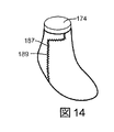
次に、図13および図14に図示されているように、第2の端部136を、底部周辺部188でかかと182に近接して、靴型174のかかと182に巻き付けて、外側側部176に取り付けることができる。また、第2の突出部155を切り欠き157に収容して嵌め込むことができ、また、直線状部分163は、縫い目189を画定するように、上縁部138の対向部分に当接させることができる。
Next, as illustrated in FIGS. 13 and 14, the
図14に図示されているように、ニット構成要素130の隣接する対向縁部は、縫い目189を画定するように、互いに当接させることができる。縫い目189は、縫製187を用いて取り付けることができる。しかし、本開示の範囲から逸脱することなく、縫い目189を、接着剤、留め具または他の取付装置を用いて取り付けることができることは正しく認識されるであろう。
As illustrated in FIG. 14, adjacent opposing edges of the knitted
次に、図15に示すいくつかの実施形態では、下方パネル185をニット構成要素130に取り付けることができる。下方パネル185は、いわゆる「ストローベル」または「ストローベル部材」と呼ぶこともできる。下方パネル185は、靴型174の底部周辺部188に近接して、ニット構成要素130の対応する縁部に取り付けることができる。下方パネル185は、縫製187、接着剤、留め具または他の装着具によって取り付けることができる。その後、図16に図示されているように、ソール構造110をニット構成要素130に取り付けることができる。いくつかの実施形態では、ソール構造110は、接着剤を用いて取り付けることができる。下方パネル185およびソール構造110は、靴型174の底部186に沿って、すなわち、着用された場合に、着用者の足の下に延びることができることは正しく認識されるであろう。
Next, in some embodiments shown in FIG. 15, the
いくつかの実施形態においては、下方パネル185および/またはソール構造110が取り付けられた場合、第1の外側ループセグメント234および第2の外側ループセグメント240(図7を参照)をニット要素131に対して取り付けることができる。たとえば、接着剤を使用する場合、第1の外側ループセグメント234および第2の外側ループセグメント240を、ソール構造110および下方パネル185に接着固定することができる。
In some embodiments, the first
最後に、靴ひも129をニット構成要素130に取り付けることができる。たとえば、図1、図5および図6に図示されているように、靴ひも129は、スロート128を横切って、行ったり来たりして延びることができ、および外側側部115および内側側部117に取り付けることができる。より具体的には、靴ひも129は、第1および第2の内側ループセグメント232,238内に収容することができる。図1、図5、図6および図25に示すいくつかの実施形態では、2つ以上の隣接する第1のループセグメント232が、靴ひも129の単一のパスを収容することができる。同様に、2つ以上の隣接するループセグメント238が、靴ひも129の単一のパスを収容することができる。図26に示す他の実施形態では、単一の第1のループセグメント232が、靴ひも129の単一のパスを収容することができる。いくつかの実施形態では、個々の第2のループセグメント238は、同様に靴ひも129を収容することができる。
Finally, the
したがって、アッパー120が組み立てられる場合、伸張性要素132を、着用者の足に対して所定の区域に配置することができる。したがって、伸張性要素132は、アッパー120のいくつかの区域に耐伸張性を与えることができ、履物製品100のフィット性およびパフォーマンスを向上させるために、アッパー120の全域に力を伝達することができ、および/または他の利点をもたらすことができる。
Thus, when the upper 120 is assembled, the
より具体的には、図1に図示されているように、アッパー120を画定するように、ニット構成要素130が組み立てられると、第1の伸張性要素200を、大略的にアッパー120の外側側部115に配置することができる。第1の内側ループセグメント232は、靴ひも129をアッパー120の外側側部115に取り付けるように、スロート128に近接して配置することができる。いくつかの実施形態では、第1の伸張性要素200は、スロート128と、アッパー120の下方部125との間に連続的に延びることもできる。言い換えると、第1の伸張性要素200は、外側側部115において、スロート128とソール構造110との間で連続的に延びることができる。さらに、第1の伸張性要素200は、スロート軸101に大略的に沿って延びているため、スロート128と下方部125との間で行ったり来たりして連続的に延びることができる。したがって、第1の伸張性要素200における張力は、たとえば、スロート領域から、下方部125および/またはソール構造110に伝達することができる。その結果、靴ひも129を締め付けることにより、第1の伸張性ストランド200の張力を増すことができ、また、下方部125およびソール構造110を、着用者の足に向かって大略的に上方に引っ張ることができる。したがって、外側側部115を着用者の足に適合させて快適にフィットさせることができる。また、第1の伸張性要素200は、たとえば、着用者の足が外側側部115に押し付けられた場合に、外側側部115の変形に耐えることができる。したがって、第1の伸張性要素200は、着用者が、横方向106において、外側に動く(すなわち、カットする)ことをより効果的に可能にする。
More specifically, as illustrated in FIG. 1, when the
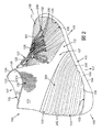
さらに、図2および図4に図示されているように、ニット構成要素130が、アッパーを画定するように組み立てられた場合、第2の伸張性要素208は、内側側部117に配置されている1つ以上のセグメントを含むことができる。第2の伸張性要素208の他のセグメントは、内側側部117から、かかと領域114を横切って外側側部115まで連続的に延びることができる。具体的には、第2の内側ループセグメント238を、靴ひも192を内側側部117に取り付けるように、スロート128に近接して内側側部117に配置することができる。対照的に、第2の外側ループセグメント240(図2および図4を参照)を、中足領域112におけるソール構造110に近接して、外側側部115に配置することができる。第2の中間区画242は、内側側部117の内側ループセグメント238から、かかと領域114を横切って、外側側部115の外側ループセグメント240まで連続的に延びることができる。言い換えると、第2の伸張性要素208は、スロート軸101に大略的に沿って延びているため、内側側部117のスロート128と、外側側部115の下方部125との間で行ったり来たりして連続的に延びることができる。したがって、第2の伸張性要素208は、内側側部117のスロート128から、かかと領域114を横切って、外側側部115の下方部125およびソール構造110に力を伝達するように構成することができる。その結果、靴ひも129を締め付けることにより、第2の伸張性ストランド208の張力を増加させることができ、また、内側側部117、かかと領域114および外側側部115を、着用者の足に向かって大略的に内側に引っ張ることができる。このことは、アッパー120に、特にかかと領域114に近接する領域において、着用者の足を大略的に圧迫させることもできる。したがって、アッパー120は、着用者の足に適合して、快適にフィットすることができる。さらに、第2の伸張性要素208は、たとえば、着用者の足が内側側部117に押し付けられた場合に、それらの領域における変形に耐えることができる。したがって、第2の伸張性要素208は、着用者が、横方向106において、外側に動く(すなわち、カットする)ことをより効果的に可能にする。
Further, as illustrated in FIGS. 2 and 4, when the
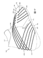
さらに、図17に図示されているように、着用者の足が(矢印256で示す)力を内側側部117に加えた場合、第2の伸張性要素208は、矢印257で示すように、その力を内側側部117から、かかと領域114を横切って、外側側部115の下方部125およびソール構造110に伝達することができる。その結果、外側側部115の下方部125および/またはソール構造110を、着用者の足に向かって内側に引っ張ることができる。力伝達の方向は、同様に逆にすることができる。たとえば、力が第2の外側ループセグメント240に近接して加えられた場合、その力を、かかと領域114を横切って、第2の内側ループセグメント238に伝達することができる。したがって、履物製品100は、横方向106において、着用者のカッティングや他の動きを効果的にサポートすることができる。
Further, as illustrated in FIG. 17, when the wearer's foot applies a force (indicated by arrow 256) to the
また、図1、図5および図6に図示されているように、第1の伸張性要素200と第2の伸張性要素208は、靴ひも129をアッパー120に取り付けるように協働することができる。具体的には、第1の内側ループセグメント232の第1の列244と、第2の内側ループセグメント238の第2の列246は、靴ひも129を収容することができる。いくつかの実施形態では、第1の列244は、スロート軸101に沿って、第2の列246からずらすことができる。具体的には、第1の列244は、第2の列246よりも、足先領域111に近接して配置することができる。言い換えると、いくつかの実施形態において、第1の列244は、中足領域112および足先領域111内に部分的に延びることができ、それに対して、第2の列246は、中足領域112内にのみ配置することができる。したがって、第1および第2の伸張性要素200,208は、特に高い負荷を受けやすい領域に設けることができる。
Also, as illustrated in FIGS. 1, 5 and 6, the first
また、靴ひも129を介して、1つの伸張性要素から別の伸張性要素に力を伝達することができる。たとえば、力が外側側部115に加えられると、第1の伸張性要素200は、その力を外側側部115から靴ひも129に伝達することができる。靴ひも129もまた同様に、この力を第2の伸張性要素208に伝達することができる。その結果、第2の伸張性要素208は、この力を内側側部117に沿って、かかと領域114を横切って、外側側部115に戻して伝達することができる。したがって、これらの力は、履物製品100の比較的大きな区域にわたって効果的に分散させることができる。また、伸張性要素200,208は、その力伝達の結果として、ニット要素131を締め付けて、および/または着用者の足に向かって押し付けることができる。したがって、履物製品100は、たとえば、着用者がカットし、地面を蹴り、または、別の方法で足を動かす場合に、高度のサポートを与えることができる。
Also, force can be transmitted from one extensible element to another via the
履物の追加的な実施形態
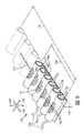
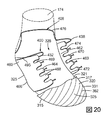
次に、図18〜図20を参照すると、本開示による履物製品300の追加的な実施形態が図示されている。履物300は、上述した履物製品100の実施形態に対応するいくつかの形状構成を含むことができる。対応する形状構成については、詳細に説明しない。しかし、異なっている形状構成については詳細に説明する。また、履物製品100に対応する履物300の構成要素は、200増やした対応する参照数字で識別されるであろう。
Additional Embodiments of Footwear Referring now to FIGS. 18-20, additional embodiments of
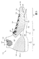
図示されているように、履物300は、ソール構造310およびアッパー320を大略的に含むことができる。アッパー320は、ニット構成要素330によって、少なくとも部分的に画定することができる。ニット構成要素330は、ニット要素331と、1つ以上の伸張性要素332とを含むことができる。
As shown, the
図18、図19および図20に示すいくつかの実施形態では、履物300は、第1の固定部材460および第2の固定部材462を含むことができる。いくつかの実施形態において、固定部材460,462は、アッパー320内に設けられる材料から成る平坦で柔軟なシートとすることができる。
In some embodiments shown in FIGS. 18, 19, and 20,
図20に図示されているように、第1の固定部材460は、上端部464および底端部466を含むことができる。いくつかの実施形態では、上端部464は、それぞれの開口部469によって分けられている複数の突出部468を含むことができる。いくつかの実施形態では、開口部469は、スリット、切り込み、または、上端部464から第1の固定部材460に沿って部分的に延びている他の開口部とすることができる。また、いくつかの実施形態では、突出部468は、丸みを付けることができる。さらに、底端部466は、外側側部315の下方部325に取り付けることができる。
As shown in FIG. 20, the first securing
同様に、第2の固定部材462は、上端部470および底端部472を含むことができる。いくつかの実施形態では、上端部470は、それぞれの開口部469によって分けられている複数の突出部474を含むことができる。さらに、底端部472は、内側側部117の下方部325に取り付けることができる。
Similarly, the second securing
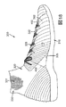
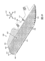
いくつかの実施形態において、ニット構成要素330の伸張性要素332は、第1の伸張性要素400を含むことができる。第1の伸張性要素400は、上述した第1の伸張性要素200の実施形態と概して同様に、履物製品100に設けることができる。しかし、第1の伸張性要素400は、外側側部315に大略的に配置され、およびソール構造310とスロート328との間に大略的に延びている複数の独立したセグメントを含むことができる。また、第1の伸張性要素400のそれらのセグメントのうちの少なくとも1つ以上は、チューブ状リブ構造362を通って延びることができる。
In some embodiments, the
具体的には、第1の伸張性要素400の典型的なセグメント495が、図20に示されている。図示されているように、第1の伸張性要素400のセグメント495は、アッパー320の下方部325および/または外側側部315のソール構造310に取り付けることができる。そこから、セグメント495は、外側側部317のそれぞれのチューブ状リブ構造416を通って、スロート328に向かって延びることができる。スロート328において、セグメント495は、第1の内側ループセグメント432を画定するように、外側面323からニット要素331を出た後、ニット要素331に向かって戻って延びることができる。セグメント495は、外側面323内に延び、ニット要素331を通って、内側面321を介してニット要素331から出て戻って延びることにより、続くことができる。セグメント495は、内側アッパー320で終端することができ、および第1の固定部材460の突出部468に取り付けることができる。したがって、セグメント495は、第1の固定部材460を介して、外側側部315上で下方部325および/またはソール構造310に取り付けることができる。第1の伸張性要素400の他のセグメントは、他のセグメントを異なる突出部468に取り付けることができることを除いて、セグメント495と同様に通すことができる。したがって、第1の伸張性要素400のセグメントは、第1の伸張性要素200に関して詳細に説明したように、履物300の外側側部315を支持することができる。
Specifically, an
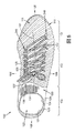
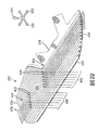
また、ニット構成要素330の伸張性要素332は、第2の伸張性要素408を含むことができる。第2の伸張性要素408は、上述した第2の伸張性要素208の実施形態と概して同様に、履物100上に配置することができる。しかし、第2の伸張性要素408は、大略的に内側側部317からかかと領域114を横切って外側側部415まで延びている複数の独立したセグメントを含むことができる。また、第2の伸張性要素408のそれらのセグメントは、内側側部317のスロート328から、かかと領域314を横切って、外側側部315の下方部325およびソール構造310まで延びることができる。さらに、第2の伸張性要素408のそれらのセグメントの少なくとも1つ以上は、チューブ状リブ構造362を通って延びることができる。
The
具体的には、第2の伸張性要素408の典型的なセグメント476が図20に示されている。図示されているように、第1の伸張性要素400のセグメント476は、アッパー320の下方部325および/または外側側部315のソール構造310に取り付けることができる。そこから、セグメント476は、外側側部417のそれぞれのチューブ状リブ構造416を通って、かかと領域314を横切って、内側側部317のスロート328に向かって延びることができる。スロート328において、セグメント476は、第2の内側ループセグメント438を画定するように、外側面323からニット要素331を出た後、ニット要素331に向かって戻って延びることができる。セグメント476は、外側面323内に延び、ニット要素331を通って、内側面321を介してニット要素331から出て戻って延びることにより、続くことができる。セグメント476は、内側アッパー320で終端することができ、および第2の固定部材462の突出部474に取り付けることができる。したがって、セグメント476は、第2の固定部材462を介して、内側側部317上で下方部325および/またはソール構造310に取り付けることができる。第2の伸張性要素408の他のセグメントは、他のセグメントを異なる突出部474に取り付けることができることを除いて、セグメント476と同様に通すことができる。したがって、第2の伸張性要素408のセグメントは、第2の伸張性要素208に関して詳細に説明したように、履物300の内側側部315およびかかと領域114を支持することができる。また、第2の伸張性要素408のセグメントは、詳細に上述した第2の伸張性要素208の実施形態と同様に、内側側部317のスロート328からの力を、かかと領域114を横切って、外側側部315の下方部325に伝達することができる。
Specifically, an
図21〜図25は、例示的な実施形態によるニット構成要素330の製造を示す。図21に図示されているように、ニット要素331は、図7に関して上述したニット要素331と実質的に同様にすることができる。また、いくつかの実施形態では、ニット構成要素330は、まず、1つ以上のチューブ状リブ構造362を通って延びている単一の連続する伸張性要素478を設けることができる。いくつかの実施形態において、伸張性要素478は、第1の端部480と、第2の端部482と、第1および第2の端部480,482の間に連続的に延びている中間区画484とを含むことができる。
21-25 illustrate the manufacture of a
第1の端部480および第2の端部482は、ニット要素431の第1の端部334から露出させることができる。中間区画484は、第1の端部334と第2の端部336との間で行ったり来たりして延びる際に、複数のチューブ状リブ構造362を通って延びることができる。
The
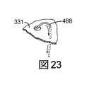
一旦、図21に示すように形成されると、伸張性要素478は、図22に図示されているように、ニット要素331に対して動かして調節することができる。たとえば、いくつかの実施形態において、伸張性要素478は、所定のチューブ状リブ構造416から引っ張ることができ、および所定のチューブ状リブ構造416から取り除くことができる。図22に図示されているように、たとえば、伸張性要素478は、上縁部338に近接して配置されたチューブ状リブ構造416内に存在する伸張性要素478は残したままで、底縁部340に近接している複数のチューブ状リブ構造416から取り除くことができる。そして、伸張性要素478の部分は、はさみ等の切断工具を用いて切断することができる。いくつかの実施形態では、伸張性要素478は、スロート区域452に近接する区域で切断することができる。いくつかの実施形態では、伸張性要素478は、スロート区域452を横断する各セグメントにおいて一回、切断することができ、およびスロート区域452から引っ張ることができる。切断する場合、伸張性要素478は、第1の伸張性要素400および第2の伸張性要素408を画定するように大略的に分けることができることは正しく認識されるであろう。また、この切断は、第1の伸張性要素400の複数の第1の自由端部488と、第2の伸張性要素408の複数の第2の自由端部490とを形成することができることは正しく認識されるであろう。
Once formed as shown in FIG. 21, the
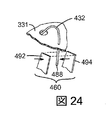
図23および図24に図示されているように、第1の自由端部488は、ループセグメント432を画定するように、ニット要素331の厚みを介して、ニット要素331から引っ張り出すことができる。そして、図24に図示されているように、第1の自由端部488を固定部材460に取り付けることができる。たとえば、いくつかの実施形態では、第1の自由端部488は、固定部材460の第1の層492と第2の層494との間に取り付けることができる。いくつかの実施形態において、第1の層492と、第2の層494と、第1の自由端部488は、接着剤を介して取り付けることができる。しかし、他の実施形態では、これらの部材は、留め具または他の装着装置を介して取り付けることができることは正しく認識されるであろう。また、第2の伸張性要素408の第2の自由端部490も、図22〜図24に示す実施形態と同様の方法で、ループセグメント438を画定するように、ニット要素331に対して調節した後、ニット要素331と通って引張り、第2の固定部材462に取り付けることができることも正しく認識されるであろう。
As illustrated in FIGS. 23 and 24, the first
したがって、履物300は、履物100に関して上述したのと同様の利点を実現することができる。また、第1および第2の固定部材460,462は、外側側部315および内側側部317に対して追加的な支持性を与えることができる。固定部材460,462はさらに、伸張性要素332を下方部325および/またはソール構造310に取り付けるための安全で便利な手段を設けることができる。
Thus, the
1つの態様においては、履物製品が提供される。その履物製品は、着用者の足を受け入れるように構成することができ、および固定具を支持するように構成することができる。その固定具は、履物製品の足に対するフィット性を選択的に変えるように構成することができる。 In one aspect, an article of footwear is provided. The footwear product can be configured to receive a wearer's foot and can be configured to support a fastener. The fixture can be configured to selectively change the fit of the footwear product to the foot.
履物製品は、ソール構造と、ソール構造に取り付けられる下方部を備えたアッパーとを備えることができる。 The footwear product may comprise a sole structure and an upper with a lower portion attached to the sole structure.
アッパーは、かかと領域と、第1の側部と、第2の側部とをさらに含むことができる。 The upper can further include a heel region, a first side, and a second side.
また、アッパーは、布地構成要素を含んでいてもよい。 The upper may also include a fabric component.
アッパーの布地構成要素は、アッパーのかかと領域と、第1の側部と、第2の側部とを少なくとも部分的に画定する布地要素と、布地要素に取り付けられる布地要素とを含むことができる。 The fabric component of the upper can include a fabric element that at least partially defines an upper heel region, a first side, and a second side, and a fabric element attached to the fabric element. .
伸張性要素は、アッパーの第1の側部に設けられた第1のセグメントを画定することができる。 The extensible element can define a first segment provided on the first side of the upper.
伸張性要素の第1のセグメントは、固定具を、アッパーの第1の側部の布地要素に取り付けるように構成することができる。 The first segment of the extensible element can be configured to attach the fastener to the fabric element on the first side of the upper.
伸張性要素は、第2の側部のアッパーの下方部に近接して配置される第2のセグメントをさらに含むことができる。 The extensible element can further include a second segment disposed proximate to a lower portion of the second side upper.
第2のセグメントは、第2の側部のアッパーの下方部に取り付けることができる。 The second segment can be attached to the lower portion of the second side upper.
伸張性要素は、第1のセグメントからかかと領域を横切って、第2のセグメントまで連続的に延びている中間セグメントを含むことができる。 The extensible element can include an intermediate segment that extends continuously from the first segment across the heel region to the second segment.
伸張性要素は、アッパーの第1の側部に加えられた力の少なくとも一部を、かかと領域を横切って、第2の側部のアッパーの下方部まで伝達するように構成することができる。 The extensible element can be configured to transmit at least a portion of the force applied to the first side of the upper across the heel region to the lower portion of the second side upper.
第2の側部は、アッパーの中足領域を画定してもよい。 The second side may define an upper midfoot region.
第2のセグメントは、中足領域に近接して設けることができる。 The second segment can be provided proximate to the midfoot region.
第1のセグメントは、固定具を収容するループを画定することができる。 The first segment can define a loop that houses the fastener.
固定具は、靴ひもとすることができる。 The fixture can be a shoelace.
第1のセグメントおよび第2のセグメントは、布地要素から少なくとも部分的に露出させることができる。 The first segment and the second segment can be at least partially exposed from the fabric element.
中間セグメントは、布地要素によって覆うことができる。 The intermediate segment can be covered by a fabric element.
布地要素は、経路を画定するチューブ状リブ構造を画定することができる。 The fabric element can define a tubular rib structure that defines a path.
中間セグメントは、その経路を通って延びることができる。 The intermediate segment can extend through the path.
チューブ状リブ構造は、第1のチューブ状リブ構造とすることができる。 The tubular rib structure can be a first tubular rib structure.
布地要素は、第2のチューブ状リブ構造と、第1のチューブ状リブ構造と第2のチューブ状リブ構造を接続するウェブとを画定することができる。 The fabric element can define a second tubular rib structure and a web connecting the first tubular rib structure and the second tubular rib structure.
布地要素は、第1のチューブ状リブ構造および第2のチューブ状リブ構造を通って連続的に延びることができる。 The fabric element can extend continuously through the first tubular rib structure and the second tubular rib structure.
履物製品は、アッパーの第1の側部に取り付けられる固定部材を備えることができる。 The footwear product may comprise a securing member attached to the first side of the upper.
第1のセグメントは、固定部材に取り付けることができる。 The first segment can be attached to the securing member.
固定部材は、アッパー内に設けることができる。 The fixing member can be provided in the upper.
伸張性要素は、第1の伸張性要素とすることができる。 The extensible element can be a first extensible element.
アッパーは、履物製品のスロートを含むことができる。 The upper may include a footwear product throat.
第1のセグメントは、アッパーの第1の側部のスロートに近接して配置することができる。 The first segment can be positioned proximate the throat on the first side of the upper.
布地構成要素は、アッパーの第2の側部のスロートと、アッパーの第2の側部の下方部との間に延びている第2の伸張性要素をさらに備えることができる。 The fabric component can further comprise a second extensible element extending between the throat on the second side of the upper and the lower portion of the second side of the upper.
第2の伸張性要素は、固定具を、アッパーの第2の側部の布地要素に取り付けるように構成された第4のセグメントを含むことができる。 The second extensible element can include a fourth segment configured to attach the fastener to the fabric element on the second side of the upper.
第2の布地要素は、第2の伸張性要素の張力を、アッパーの第2の側部の下方部に伝達するために構成することができる。 The second fabric element can be configured to transmit the tension of the second extensible element to the lower portion of the second side of the upper.
第4のセグメントは、アッパーの第2の側部のソール構造に取り付けることができる。 The fourth segment can be attached to the sole structure on the second side of the upper.
履物製品は、アッパーの第2の側部に取り付けられる固定部材をさらに備えることができる。 The footwear product may further comprise a securing member attached to the second side of the upper.
第4のセグメントは、固定部材に取り付けることができる。 The fourth segment can be attached to the securing member.
第1の側部は、アッパーの内側側部とすることができる。第2の側部は、アッパーの外側側部とすることができる。 The first side can be the inner side of the upper. The second side can be the outer side of the upper.
アッパーは、足を受け入れるように構成される空洞を画定することができる。 The upper can define a cavity configured to receive a foot.
アッパーは、空洞内への足の経路を形成するように構成された開口部を画定することもできる。 The upper may also define an opening configured to form a foot path into the cavity.
アッパーは、履物製品のスロートを含むことができる。 The upper may include a footwear product throat.
スロートは、開口部から離れてスロート軸に沿って延びていてもよい。 The throat may extend along the throat axis away from the opening.
伸張性要素は、スロート軸に沿って大略的に延びる際に、第2の側部のスロートと下方部との間を行ったり来たりして連続的に延びることができる。 The extensible element can extend continuously back and forth between the throat and the lower portion of the second side as it extends generally along the throat axis.
伸張性要素は、複数のループを画定することができる。 The extensible element can define a plurality of loops.
複数のループは、第1の側部のスロートに近接して配列することができる。 The plurality of loops can be arranged proximate to the first side throat.
複数のループは、大略的にスロート軸に沿って方向付けられた列状に配置することができる。 The plurality of loops can be arranged in rows oriented generally along the throat axis.
複数のループは、固定具を収容して、その固定具をアッパーの第1の側部に取り付けるように構成することができる。 The plurality of loops can be configured to receive a fixture and attach the fixture to the first side of the upper.
複数のループは、大略的にアッパーの第1の側部のスロート軸に沿って方向付けられた第1の列状に配置することができる。 The plurality of loops can be arranged in a first row generally oriented along the throat axis of the first side of the upper.
布地構成要素は、アッパーの第2の側部のスロートと、アッパーの第2の側部の下方部との間に延びている第2の伸張性要素をさらに備えることができる。 The fabric component can further comprise a second extensible element extending between the throat on the second side of the upper and the lower portion of the second side of the upper.
第2の伸張性要素は、大略的にスロート軸に沿って方向付けられた第2の列状に配列された複数の第2のループを画定することができる。 The second extensible element can define a plurality of second loops arranged in a second row generally oriented along the throat axis.
複数の第2のループは、固定具を収容して、その固定具をアッパーの第2の側部に取り付けるように構成することができる。 The plurality of second loops can be configured to receive a fixture and attach the fixture to the second side of the upper.
第1の列と第2の列は、スロート軸に沿ってずらすことができる。 The first row and the second row can be shifted along the throat axis.
布地構成要素は、一体ニット構造で形成されたニット構成要素とすることができる。 The fabric component can be a knit component formed with a unitary knit structure.
布地要素は、ニット要素とすることができる。 The fabric element can be a knitted element.
伸張性要素は、ニット要素とともに一体ニット構造で形成することができる。 The extensible element can be formed in a unitary knit structure with the knit element.
固定具は、履物製品の足に対するフィット性を選択的に変えるように構成することができる。 The fixture can be configured to selectively change the fit of the footwear product to the foot.
履物製品は、ソール構造と、足を受け入れるように構成された空洞を画定するアッパーとを備えていてもよい。 The footwear product may include a sole structure and an upper that defines a cavity configured to receive a foot.
アッパーは、ソール構造に取り付けられる下方部を含むことができる。 The upper can include a lower portion attached to the sole structure.
アッパーは、かかと領域と、第1の側部と、第2の側部とを含むことができる。 The upper can include a heel region, a first side, and a second side.
アッパーは、一体ニット構造で形成されたニット構成要素をさらに含むことができる。 The upper can further include a knit component formed in a unitary knit structure.
アッパーは、空洞内への足の経路を形成するように構成された開口部を画定することができる。 The upper may define an opening configured to form a foot path into the cavity.
アッパーは、第1の側部と第2の側部との間に設けられるスロートをさらに含むことができ、この場合、そのスロートは、開口部から延びている。 The upper can further include a throat provided between the first side and the second side, wherein the throat extends from the opening.
アッパーのニット構成要素は、アッパーのかかと領域と、第1の側部と、第2の側部とを少なくとも部分的に画定するニット要素と、そのニット要素とともに一体ニット構造で形成される第1の伸張性要素とを含むことができる。第1の伸張性要素は、第1の側部のスロートからかかと領域を横切って、第2の側部の下方部まで連続的に延びることができる。 The upper knitted component includes a knit element that at least partially defines an upper heel region, a first side, and a second side, and a first knit structure formed with the knit element in an integral knit structure. Of extensible elements. The first extensible element can extend continuously from the throat of the first side across the heel region to the lower part of the second side.
また、ニット構成要素は、ニット要素とともに一体ニット構造で形成される第2の伸張性要素も含むことができる。第2の伸張性要素は、第2の側部のスロートから、第2の側部の下方部まで連続的に延びることができる。 The knit component can also include a second extensible element that is formed with the knit element in an integral knit structure. The second extensible element can extend continuously from the throat of the second side to the lower portion of the second side.
第1の伸張性要素は、第1の側部のスロートに配置され、および第1の側部で固定具を収容するように構成される、少なくとも1つの第1のセグメントを画定することができる。 The first extensible element may define at least one first segment disposed in the throat of the first side and configured to receive a fastener on the first side. .
第2の伸張性要素は、第2の側部のスロートに配置され、および第2の側部で固定具を収容するように構成される、少なくとも1つの第2のセグメントを画定することができる。 The second extensible element may define at least one second segment disposed at the second side throat and configured to receive a fastener at the second side. .
第1の伸張性要素は、第2の側部の下方部の近傍で、ソール構造に取り付けることができる。 The first extensible element can be attached to the sole structure near the lower portion of the second side.
第2の伸張性要素は、第2の側部の下方部の近傍で、ソール構造に取り付けられる。 The second extensible element is attached to the sole structure near the lower portion of the second side.
履物製品は、第1の側部の近傍で、アッパー内に設けられている第1の固定部材をさらに備えることができる。 The footwear product may further include a first fixing member provided in the upper in the vicinity of the first side portion.
第1の固定部材は、第1の側部の下方部に取り付けることができる。 The first fixing member can be attached to a lower portion of the first side portion.
第1の伸張性要素は、第1の固定部材に取り付けることができる。 The first extensible element can be attached to the first securing member.
履物製品は、第2の側部の近傍で、アッパー内に設けられている第2の固定部材をさらに備えることができる。 The footwear product may further include a second fixing member provided in the upper in the vicinity of the second side portion.
第2の固定部材は、第2の側部の下方部に取り付けることができる。 The second fixing member can be attached to the lower part of the second side.
第2の伸張性要素は、第2の固定部材に取り付けることができる。 The second extensible element can be attached to the second securing member.
1つの態様においては、履物製品用アッパーを画定するように構成することができるニット構成要素が提供される。 In one aspect, a knit component is provided that can be configured to define an upper for a footwear product.
アッパーは、足先領域と、かかと領域と、足先領域とかかと領域との間に延びている第1の側部と、足先領域とかかと領域との間に延びている第2の側部とを含むことができる。 The upper includes a toe region, a heel region, a first side portion extending between the toe region and the heel region, and a second side portion extending between the toe region and the heel region. Can be included.
ニット構成要素は、ニット要素と、ニット要素とともに一体ニット構造で形成された伸張性ストランドとを備えることができる。 The knitted component can comprise a knitted element and an extensible strand formed in a unitary knitted structure with the knit element.
ニット要素は、前面および裏面を含むことができる。 The knit element can include a front surface and a back surface.
ニット要素は、第1の端部および第2の端部を含むことができる。 The knitted element can include a first end and a second end.
ニット要素は、第1の端部と第2の端部との間に大略的に延びているチューブ状リブ構造をさらに含むことができる。 The knitted element can further include a tubular rib structure extending generally between the first end and the second end.
チューブ状リブ構造は、第2の端部に近接して設けられた開端部を含むことができる。 The tubular rib structure can include an open end provided proximate to the second end.
伸張性要素は、チューブ状リブ構造内に収容される第1のセグメントを含むことができる。 The extensible element can include a first segment housed within the tubular rib structure.
伸張性要素は、第1のセグメントから延び、および開端部から出て延びている第2のセグメントをさらに含むことができる。 The extensible element can further include a second segment extending from the first segment and extending out of the open end.
伸張性要素は、第1のセグメントから延び、前面でニット要素から出て、前面を通ってニット要素内に戻って延びる第3のセグメントをさらに含むことができる。 The extensible element can further include a third segment that extends from the first segment, exits the knit element at the front surface, and extends back through the front surface and into the knit element.
ニット要素の第1の端部は、アッパーの第2の側部に取り付けられるように構成することができる。 The first end of the knitted element can be configured to be attached to the second side of the upper.
ニット要素の第2の端部は、アッパーの第2の側部に取り付けられるように構成することができる。 The second end of the knitted element can be configured to be attached to the second side of the upper.
第1のセグメントは、第1の側部からチューブ状リブ構造を通って、かかと領域を横切って、アッパーの第2の側部まで延びるように構成することができる。 The first segment can be configured to extend from the first side, through the tubular rib structure, across the heel region, to the second side of the upper.
第2のセグメントは、アッパーの第2の側部のニット要素に対して取り付けられるように構成することができる。 The second segment can be configured to be attached to a knit element on the second side of the upper.
第1のセグメントは、アッパーの第1の側部に設けられるように構成することができる。 The first segment can be configured to be provided on the first side of the upper.
伸張性要素は、チューブ状リブ構造を通る第1の方向に沿って延び、第3のセグメントにおいて、ニット要素から出て、チューブ状リブ構造に再び入り、そして、第2の方向に沿って、チューブ状リブ構造に沿って戻って延びることができる。第1の方向は、第2の方向の逆にすることができる。 The extensible element extends along a first direction through the tubular rib structure, exits the knit element at the third segment, reenters the tubular rib structure, and along the second direction, It can extend back along the tubular rib structure. The first direction can be the reverse of the second direction.
伸張性要素は、チューブ状リブ構造を通って延び、第3のセグメントでニット要素から出て、ニット要素に再び入り、そして、裏面を通ってニット要素から出ることができる。 The extensible element can extend through the tubular rib structure, exit the knit element at the third segment, reenter the knit element, and exit the knit element through the back surface.
1つの態様においては、履物製品用アッパーを形成する方法が提供される。 In one aspect, a method for forming an upper for a footwear product is provided.
したがって、布地要素および伸張性要素を含む布地構成要素を形成することができる。 Thus, a fabric component can be formed that includes a fabric element and an extensible element.
布地要素は、前面および裏面を含むことができる。 The fabric element can include a front surface and a back surface.
布地要素は、第1の端部および第2の端部を含むことができる。 The fabric element can include a first end and a second end.
布地要素は、第1の端部と第2の端部との間に大略的に延びているチューブ状リブ構造をさらに含むことができる。 The fabric element can further include a tubular rib structure extending generally between the first end and the second end.
布地要素は、伸張性要素の第1のセグメントがチューブ状リブ構造内に収容されるように通すことができる。 The fabric element can be threaded such that the first segment of the extensible element is received within the tubular rib structure.
布地要素は、伸張性要素の第2のセグメントが、第1のセグメントから延びて、チューブ状リブ構造の開端部から出て延びるように通すことができる。 The fabric element can be threaded so that the second segment of the extensible element extends from the first segment and out of the open end of the tubular rib structure.
布地要素は、伸張性要素の第3のセグメントが第1のセグメントから延びて、前面で布地要素から出た後、前面を通って布地要素内に戻って延びるように通すことができる。 The fabric element can be threaded so that the third segment of the extensible element extends from the first segment and exits the fabric element on the front side and then extends back into the fabric element through the front side.
布地構成要素は、アッパーの第1の側部と、足先領域と、第2の側部と、かかと領域とを画定するように組立てることができる。 The fabric component can be assembled to define a first side of the upper, a toe region, a second side, and a heel region.
布地構成要素を組立てることは、布地構成要素を第2の側部から足先領域を横切って、第1の側部を横切って、かかと領域を横切って、第2の側部に戻して巻き付けることを含むことができる。 Assembling the fabric component involves wrapping the fabric component from the second side across the toe area, across the first side, across the heel area, and back to the second side. Can be included.
布地構成要素を組立てることは、アッパーの第2の側部に、布地要素の第1の端部を設けることと、アッパーの第2の側部に、布地要素の第2の端部を設けることとを含むことができる。 Assembling the fabric component includes providing a first end of the fabric element on the second side of the upper and providing a second end of the fabric element on the second side of the upper. Can be included.
布地構成要素を組立てることは、第1のセグメントを、第1の側部からチューブ状リブ構造を通して、かかと領域を横切って、アッパーの第2の側部まで延ばすことを含むことができる。 Assembling the fabric component can include extending the first segment from the first side, through the tubular rib structure, across the heel region, to the second side of the upper.
布地構成要素を組立てることは、アッパーの第2の側部において、布地要素に対して第2のセグメントを取り付けることを含んでいてもよい。 Assembling the fabric component may include attaching a second segment to the fabric element at the second side of the upper.
布地構成要素を組立てることは、アッパーの第1の側部に第1のセグメントを設けることを含むことができる。 Assembling the fabric component can include providing a first segment on a first side of the upper.
伸張性要素は、チューブ状リブ構造を通して第1の方向に沿って延ばすことができる。 The extensible element can extend along the first direction through the tubular rib structure.
第3のセグメントにループを画定することができ、伸張性要素を、第2の方向に沿って、チューブ状リブ構造に沿って戻って延ばすことができる。第1の方向は、第2の方向の逆にすることができる。 A loop can be defined in the third segment, and the extensible element can extend back along the tubular rib structure along the second direction. The first direction can be the reverse of the second direction.
伸張性要素は、チューブ状リブ構造を通して延ばすことができる。 The extensible element can extend through the tubular rib structure.
第3のセグメントにループを画定することができる。 A loop can be defined in the third segment.
伸張性要素は、第3のセグメントから、布地要素の裏面を通って、布地要素から出るように延ばすことができる。 The extensible element can extend from the third segment through the back side of the fabric element and out of the fabric element.
固定部材は、布地要素の裏面から露出されている布地要素の部分に取り付けることができる。 The securing member can be attached to the portion of the fabric element that is exposed from the back surface of the fabric element.
布地要素を形成することは、ニット要素を編むことと、ニット要素とともに一体ニット構造で形成された伸張性要素を組み込むこととを含むことができる。 Forming the fabric element can include knitting the knit element and incorporating an extensible element formed with the knit element in a unitary knit structure.
上記の態様は、一般的に、アッパーに使用される材料要素の数を減らすのに役に立ち、アッパーの製造効率およびリサイクル性を高めながら、廃棄物を減らすことができる。 The above aspects generally help reduce the number of material elements used in the upper, and can reduce waste while increasing the manufacturing efficiency and recyclability of the upper.
本開示のさまざまな実施形態について説明してきたが、その説明は、限定的であるというよりも、例示的であることが意図されており、また、当業者には、本開示の範囲内において、より多くの実施形態および実施態様が可能であることは明らかであろう。したがって、本開示は、添付クレームおよびそれらの等価物の観点を除いて限定すべきではない。また、さまざまな変更および変形を、添付クレームの範囲内で行うことができる。さらに、前述のクレームを参照する場合の「いずれかの」という用語は、クレームにおいて用いる場合、(i)いずれか一項、または、(ii)参照される2つ以上のクレームのいずれかの組合せを意味することが意図されている。 Although various embodiments of the present disclosure have been described, the description is intended to be illustrative rather than limiting, and those skilled in the art can It will be apparent that many more embodiments and implementations are possible. Accordingly, the disclosure should not be limited except in terms of the appended claims and their equivalents. Various changes and modifications may be made within the scope of the appended claims. Furthermore, the term “any” when referring to a claim above, when used in the claim, (i) any one term, or (ii) any combination of two or more referenced claims Is meant to mean
これとは別に、別の態様では、アッパーを設けてもよく、アッパーは、かかと領域と、第1の側部と、第2の側部とを備え、アッパーはさらに、布地構成要素を含んでいる。 Alternatively, in another aspect, an upper may be provided, the upper comprising a heel region, a first side, and a second side, the upper further including a fabric component. Yes.
布地構成要素は、アッパーのかかと領域と、第1の側部と、第2の側部とを少なくとも部分的に画定する布地要素と、その布地要素に取り付けられる伸張性要素とを含むことができる。 The fabric component can include a fabric element that at least partially defines a heel region of the upper, a first side, and a second side, and an extensible element attached to the fabric element. .
伸張性要素は、アッパーの第1の側部に配置される第1のセグメントを画定することができる。 The extensible element can define a first segment disposed on the first side of the upper.
伸張性要素の第1のセグメントは、アッパーの第1の側部において、固定具を布地要素に取り付けるように構成することができる。 The first segment of the extensible element can be configured to attach the fastener to the fabric element on the first side of the upper.
伸張性要素は、第2の側部において、アッパーの下方部に近接して配置される第2のセグメントをさらに含むことができる。 The extensible element may further include a second segment disposed on the second side and proximate to a lower portion of the upper.
第2のセグメントは、第2の側部において、アッパーの下方部に対して取り付けることができる。 The second segment can be attached to the lower portion of the upper on the second side.
伸張性要素は、第1のセグメントから、かかと領域を横切って、第2のセグメントまで連続的に延びている中間セグメントをさらに含むことができる。 The extensible element can further include an intermediate segment that extends continuously from the first segment across the heel region to the second segment.
伸張性要素は、アッパーの第1の側部に加えられた力の少なくとも一部を、かかと領域を横切って、第2の側部のアッパーの下方部に伝達するように構成することができる。 The extensible element may be configured to transmit at least a portion of the force applied to the first side of the upper across the heel region to the lower portion of the second side upper.
アッパーは、着用者の足を受け入れるように構成することができ、および固定具を支持するように構成することができ、固定具は、アッパーの足に対するフィット性を選択的に変えるように構成される。 The upper can be configured to accept a wearer's foot and can be configured to support a fastener, the fastener being configured to selectively change the fit of the upper to the foot. The
第2の側部は、アッパーの中足領域を画定することができ、第2のセグメントは、中足領域に近接して配置される。 The second side can define an upper metatarsal region, and the second segment is disposed proximate to the metatarsal region.
固定具は、靴ひもとすることができる。 The fixture can be a shoelace.
第1のセグメントは、固定具を収容するループを画定することができる。 The first segment can define a loop that houses the fastener.
第1のセグメントおよび第2のセグメントは、布地要素から少なくとも部分的に露出させることができ、中間セグメントは、布地要素によって覆われている。 The first segment and the second segment can be at least partially exposed from the fabric element, and the intermediate segment is covered by the fabric element.
布地要素は、経路を画定するチューブ状リブ構造を画定することができる。 The fabric element can define a tubular rib structure that defines a path.
中間セグメントは、その経路を通って延びることができる。 The intermediate segment can extend through the path.
布地要素は、一体ニット構造で形成されたニット要素とすることができる。 The fabric element may be a knitted element formed with a unitary knitted structure.
Claims (36)
ソール構造と、
前記ソール構造に取り付けられる下方部を備えたアッパーであって、かかと領域と、第1の側部と、第2の側部とをさらに含み、布地構成要素をさらに含むアッパーと、
を備え、前記アッパーの前記布地構成要素は、
前記アッパーの前記かかと領域と、前記第1の側部と、前記第2の側部とを少なくとも部分的に画定する布地要素と、
前記布地要素に取り付けられる伸張性要素と、
を含み、
前記伸張性要素は、前記アッパーの第1の側部に配置される第1のセグメントを画定し、
前記伸張性要素の第1のセグメントは、前記固定具を、前記アッパーの第1の側部の前記布地要素に取り付けるように構成され、
前記伸張性要素は、前記第2の側部において、前記アッパーの前記下方部に近接して配置される第2のセグメントをさらに含み、
前記第2のセグメントは、前記第2の側部において、前記アッパーの前記下方部に対して取り付けられ、
前記伸張性要素は、前記第1のセグメントから前記かかと領域を横切って、前記第2のセグメントまで連続的に延びている中間セグメントをさらに含み、
前記伸張性要素は、前記アッパーの第1の側部に加えられた力の少なくとも一部を、前記かかと領域を横切って、前記第2の側部の前記アッパーの前記下方部に伝達するように構成される、履物製品。 An article of footwear configured to receive a wearer's foot and configured to support a fastener, wherein the fastener is configured to selectively change the fit of the footwear product to the foot. A footwear product, the footwear product comprising:
Sole structure,
An upper with a lower portion attached to the sole structure, further comprising a heel region, a first side, a second side, and further comprising a fabric component;
And the fabric component of the upper is
A fabric element that at least partially defines the heel region of the upper, the first side, and the second side;
An extensible element attached to the fabric element;
Including
The extensible element defines a first segment disposed on a first side of the upper;
A first segment of the extensible element is configured to attach the fastener to the fabric element on a first side of the upper;
The extensible element further includes a second segment disposed on the second side proximate to the lower portion of the upper;
The second segment is attached to the lower portion of the upper at the second side;
The extensible element further includes an intermediate segment extending continuously from the first segment across the heel region to the second segment;
The extensible element transmits at least a portion of the force applied to the first side of the upper across the heel region to the lower portion of the upper of the second side. Composed of footwear products.
前記第2のセグメントは、前記中足領域に近接して配置される、請求項1に記載の履物製品。 The second side defines a midfoot region of the upper;
The footwear product of claim 1, wherein the second segment is disposed proximate to the midfoot region.
前記中間セグメントは、前記経路を通って延びる、請求項1〜5のいずれか一項に記載の履物製品。 The fabric element defines a tubular rib structure defining a path;
The footwear product according to any one of claims 1 to 5, wherein the intermediate segment extends through the path.
前記布地要素は、第2のチューブ状リブ構造と、前記第1のチューブ状リブ構造と前記第2のチューブ状リブ構造とを接続するウェブとを画定し、
前記伸張性要素は、前記第1のチューブ状リブ構造および前記第2のチューブ状リブ構造を通って連続的に延びている、請求項1〜6のいずれか一項に記載の履物製品。 The tubular rib structure is a first tubular rib structure;
The fabric element defines a second tubular rib structure and a web connecting the first tubular rib structure and the second tubular rib structure;
The article of footwear according to any one of the preceding claims, wherein the extensible element extends continuously through the first tubular rib structure and the second tubular rib structure.
前記第1のセグメントは、前記固定部材に取り付けられる、請求項1〜7のいずれか一項に記載の履物製品。 A fixing member attached to the first side of the upper;
The footwear product according to claim 1, wherein the first segment is attached to the fixing member.
前記アッパーは、前記履物製品のスロートを含み、
前記第1のセグメントは、前記アッパーの前記第1の側部の前記スロートに近接して配置され、
前記布地構成要素は、前記アッパーの前記第2の側部の前記スロートと、前記アッパーの前記第2の側部の前記下方部との間に延びている第2の伸張性要素をさらに備え、
前記第2の伸張性要素は、前記固定具を、前記アッパーの前記第2の側部において、前記布地要素に取り付けるように構成された第4のセグメントを含み、
前記第2の伸張性要素は、前記第2の伸張性要素の張力を、前記アッパーの前記第2の側部の前記下方部に伝達するために構成される、請求項1〜9のいずれか一項に記載の履物製品。 The extensible element is a first extensible element;
The upper includes a throat of the footwear product;
The first segment is disposed proximate to the throat on the first side of the upper;
The fabric component further comprises a second extensible element extending between the throat of the second side of the upper and the lower portion of the second side of the upper;
The second extensible element includes a fourth segment configured to attach the fastener to the fabric element at the second side of the upper;
10. The second stretchable element according to any of claims 1-9, wherein the second stretchable element is configured to transmit the tension of the second stretchable element to the lower portion of the second side of the upper. Footwear product according to one item.
前記第4のセグメントは、前記固定部材に取り付けられる、請求項1〜11のいずれか一項に記載の履物製品。 A fixing member attached to the second side portion of the upper;
The footwear product according to any one of claims 1 to 11, wherein the fourth segment is attached to the fixing member.
前記アッパーは、前記足の前記空洞内への経路を形成するように構成された開口部を画定し、
前記アッパーは、前記履物製品のスロートを含み、
前記スロートは、スロート軸に沿って前記開口部から延び、
前記伸張性要素は、前記伸張性要素が大略的に前記スロート軸に沿って延びる際に、前記スロートと、前記第2の側部の前記下方部との間で行ったり来たりして連続的に延びている、請求項1〜13のいずれか一項に記載の履物製品。 The upper defines a cavity configured to receive the foot;
The upper defines an opening configured to form a pathway into the cavity of the foot;
The upper includes a throat of the footwear product;
The throat extends from the opening along a throat axis;
The extensible element is continuous between the throat and the lower portion of the second side when the extensible element extends generally along the throat axis. Footwear product according to any one of the preceding claims, which extends to
前記複数のループは、前記第1の側部の前記スロートに近接して配置され、
前記複数のループは、大略的に前記スロート軸に沿って向けられている列状に配置され、
前記複数のループは、前記固定具を収容して、前記固定具を前記アッパーの第1の側部に取り付けるように構成される、請求項1〜14のいずれか一項に記載の履物製品。 The extensible element defines a plurality of loops;
The plurality of loops are disposed proximate to the throat of the first side;
The plurality of loops are arranged in a row generally oriented along the throat axis,
15. An article of footwear according to any one of the preceding claims, wherein the plurality of loops are configured to receive the fixture and attach the fixture to a first side of the upper.
前記布地構成要素は、前記アッパーの前記第2の側部の前記スロートと、前記アッパーの前記第2の側部の前記下方部との間に延びる第2の伸張性要素をさらに備え、
前記第2の伸張性要素は、大略的に前記スロート軸に沿って向けられている第2の列状に配置された複数の第2のループを画定し、
前記複数の第2のループは、前記固定具を収容して、前記固定具を前記アッパーの前記第2の側部に取り付けるように構成され、
前記第1の列と前記第2の列は、前記スロート軸に沿ってずらされている、請求項1〜15のいずれか一項に記載の履物製品。 The plurality of loops are a plurality of loops arranged in a first row generally oriented along the throat axis of the first side of the upper,
The fabric component further comprises a second extensible element extending between the throat of the second side of the upper and the lower portion of the second side of the upper;
The second extensible element defines a plurality of second loops arranged in a second row generally oriented along the throat axis;
The plurality of second loops are configured to receive the fixture and attach the fixture to the second side of the upper,
The footwear product according to any one of claims 1 to 15, wherein the first row and the second row are shifted along the throat axis.
前記布地要素はニット要素であり、
前記伸張性要素は、前記ニット要素とともに一体ニット構造で形成される、請求項1〜16のいずれか一項に記載の履物製品。 The fabric component is a knit component formed in an integral knit structure,
The fabric element is a knit element;
17. An article of footwear according to any one of the preceding claims, wherein the extensible element is formed in a unitary knit structure with the knit element.
ソール構造と、
前記足を受け入れるように構成された空洞を画定するアッパーであって、前記ソール構造に取り付けられる下方部を含み、かかと領域と、第1の側部と、第2の側部とを含み、一体ニット構造で形成されたニット構成要素をさらに含むアッパーと、
を備え、
前記アッパーは、前記足の前記空洞内への経路を形成するように構成された開口部を画定し、
前記アッパーは、前記第1の側部と前記第2の側部との間に配置されるスロートをさらに含み、前記スロートは、前記開口部から延び、
前記アッパーの前記ニット構成要素は、
前記アッパーの前記かかと領域と、前記第1の側部と、前記第2の側部とを少なくとも部分的に画定するニット要素と、
前記ニット要素とともに一体ニット構造で形成される第1の伸張性要素であって、前記第1の側部の前記スロートから前記かかと領域を横切って、前記第2の側部の前記下方部まで連続的に延びている第1の伸張性要素と、
前記ニット要素とともに一体ニット構造で形成される第2の伸張性要素であって、前記第2の側部の前記スロートから、前記第2の側部の前記下方部まで連続的に延びている第2の伸張性要素と、
を含み、
前記第1の伸張性要素は、前記第1の側部の前記スロートに配置され、および前記第1の側部において、前記固定具を収容するように構成される、少なくとも1つの第1のセグメントを画定し、
前記第2の伸張性要素は、前記第2の側部の前記スロートに配置され、および前記第2の側部において、前記固定具を収容するように構成される、少なくとも1つの第2のセグメントを画定する、履物製品。 An article of footwear configured to receive a wearer's foot and configured to support a fastener, wherein the fastener is configured to selectively change the fit of the footwear product to the foot. A footwear product, the footwear product comprising:
Sole structure,
An upper defining a cavity configured to receive the foot, including a lower portion attached to the sole structure, including a heel region, a first side, and a second side, An upper further comprising a knit component formed of a knit structure;
With
The upper defines an opening configured to form a pathway into the cavity of the foot;
The upper further includes a throat disposed between the first side and the second side, the throat extending from the opening,
The knit component of the upper is
A knit element that at least partially defines the heel region of the upper, the first side, and the second side;
A first extensible element formed in a unitary knit structure with the knit element, continuous from the throat of the first side to the lower part of the second side across the heel region A first extensible element extending in a general manner;
A second extensible element formed in a unitary knit structure with the knit element and extending continuously from the throat of the second side to the lower part of the second side. Two extensible elements;
Including
At least one first segment, wherein the first extensible element is disposed in the throat of the first side and is configured to receive the fastener at the first side. Define
At least one second segment, wherein the second extensible element is disposed in the throat of the second side and is configured to receive the fixture at the second side Defining footwear products.
前記第2の伸張性要素は、前記第2の側部の前記下方部に近接して前記ソール構造に取り付けられる、請求項18に記載の履物製品。 The first extensible element is attached to the sole structure proximate to the lower portion of the second side;
19. An article of footwear according to claim 18, wherein the second extensible element is attached to the sole structure proximate the lower portion of the second side.
前記第2の側部に近接して前記アッパー内に設けられる第2の固定部材であって、前記第2の固定部材が、前記第2の側部の前記下方部に取り付けられ、前記第2の伸張性要素が前記第2の固定部材に取り付けられる、第2の固定部材と、
をさらに備える、請求項18または19に記載の履物製品。 A first fixing member provided in the upper portion adjacent to the first side portion, wherein the first fixing member is attached to the lower portion of the first side portion; A first securing member, wherein the extensible element is attached to the first securing member;
A second fixing member provided in the upper portion adjacent to the second side portion, wherein the second fixing member is attached to the lower portion of the second side portion; A second securing member, wherein the extensible element is attached to the second securing member;
20. An article of footwear according to claim 18 or 19, further comprising:
ニット要素と、
前記ニット要素とともに一体ニット構造で形成された伸張性ストランドと、
を備え、
前記ニット要素は、前面および裏面を含み、
前記ニット要素は、第1の端部および第2の端部を含み、
前記ニット要素は、前記第1の端部と前記第2の端部との間に大略的に延びているチューブ状リブ構造をさらに含み、
前記チューブ状リブ構造は、前記第2の端部に近接して配置される開端部を含み、
前記伸張性要素は、前記チューブ状リブ構造内に収容される第1のセグメントを含み、
前記伸張性要素は、前記第1のセグメントから延び、および前記開端部から出て延びる第2のセグメントをさらに含み、
前記伸張性要素は、前記第1のセグメントから延び、前記前面で前記ニット要素から出て、前記前面を通って前記ニット要素内に戻って延びている第3のセグメントをさらに含み、
前記ニット要素の前記第1の端部は、前記アッパーの前記第2の側部に取り付けられるように構成され、
前記ニット要素の前記第2の端部は、前記アッパーの前記第2の側部に取り付けられるように構成され、
前記第1のセグメントは、前記第1の側部から前記チューブ状リブ構造を通って、前記かかと領域を横切って、前記アッパーの前記第2の側部まで延びるように構成され、
前記第2のセグメントは、前記アッパーの前記第2の側部の前記ニット要素に対して取り付けられるように構成され、
前記第1のセグメントは、前記アッパーの前記第1の側部に配置されるように構成される、ニット構成要素。 A knit component configured to define an upper for a footwear product, wherein the upper extends between a foot region, a heel region, and the foot region and the heel region. Including a side and a second side extending between the toe region and the heel region, the knit component comprising:
Knitted elements,
An extensible strand formed in an integral knit structure with the knit element;
With
The knit element includes a front surface and a back surface;
The knit element includes a first end and a second end;
The knit element further includes a tubular rib structure extending generally between the first end and the second end;
The tubular rib structure includes an open end disposed proximate to the second end;
The extensible element includes a first segment received within the tubular rib structure;
The extensible element further includes a second segment extending from the first segment and extending out of the open end;
The extensible element further includes a third segment extending from the first segment, extending from the knit element at the front surface, and extending back through the front surface into the knit element;
The first end of the knit element is configured to be attached to the second side of the upper;
The second end of the knit element is configured to be attached to the second side of the upper;
The first segment is configured to extend from the first side through the tubular rib structure, across the heel region, to the second side of the upper;
The second segment is configured to be attached to the knit element on the second side of the upper;
The knit component, wherein the first segment is configured to be disposed on the first side of the upper.
前記第1の方向は、前記第2の方向の逆である、請求項21に記載のニット構成要素。 The extensible element extends through the tubular rib structure along a first direction, exits the knit element at a third segment, reenters the tubular rib structure, and follows a second direction. Extending back along the tubular rib structure,
The knit component of claim 21, wherein the first direction is the reverse of the second direction.
布地要素および伸張性要素を含む布地構成要素を形成することであって、前記布地要素が前面および裏面を含み、前記布地要素が第1の端部および第2の端部を含み、前記布地要素が、前記第1の端部と前記第2の端部との間に大略的に延びているチューブ状リブ構造をさらに含むことと、
前記伸張性要素の第1のセグメントが前記チューブ状リブ構造内に収容されるように、前記伸張性要素を通すことと、
前記伸張性要素の第2のセグメントが、前記第1のセグメントから延びて、前記チューブ状リブ構造の開端部から出て延びるように、前記伸張性要素を通すことと、
前記伸張性要素の第3のセグメントが、前記第1のセグメントから延びて、前記前面で前記布地要素から出て延び、前記前面を通って前記布地要素内に戻って延びるように、前記伸張性要素を通すことと、
前記アッパーの第1の側部と、足先領域と、第2の側部と、かかと領域とを画定するように、前記布地構成要素を組み立てることと、
を含み、
前記布地構成要素を組み立てることは、前記布地構成要素を前記第2の側部から、前記足先領域を横切って、前記第1の側部を横切って、前記かかと領域を横切って、前記第2の側部に戻って巻き付けることを含み、
前記布地構成要素を組み立てることは、前記布地要素の前記第1の端部を、前記アッパーの第2の側部に設けることと、前記布地要素の前記第2の端部を、前記アッパーの第2の側部に設けることとを含み、
前記布地構成要素を組み立てることは、前記第1のセグメントを、前記第1の側部から前記チューブ状リブ構造を通して、前記かかと領域を横切って、前記アッパーの前記第2の側部まで延ばすことを含み、
前記布地構成要素を組み立てることは、前記アッパーの前記第2の側部において、前記布地要素に対して前記第2のセグメントを取り付けることを含み、
前記布地構成要素を組み立てることは、前記アッパーの前記第1の側部に前記第1のセグメントを設けることを含む方法。 A method of forming an upper for footwear products, comprising:
Forming a fabric component comprising a fabric element and an extensible element, wherein the fabric element includes a front surface and a back surface, the fabric element including a first end and a second end; Further includes a tubular rib structure extending generally between the first end and the second end;
Passing the extensible element such that a first segment of the extensible element is received within the tubular rib structure;
Passing the extensible element such that a second segment of the extensible element extends from the first segment and extends out of an open end of the tubular rib structure;
The extensible element such that a third segment of the extensible element extends from the first segment, extends out of the fabric element at the front surface, and extends back through the front surface into the fabric element. Through the elements,
Assembling the fabric component to define a first side of the upper, a toe region, a second side, and a heel region;
Including
Assembling the fabric component includes assembling the fabric component from the second side, across the toe region, across the first side, across the heel region, Including wrapping back to the side of the
Assembling the fabric component includes providing the first end of the fabric element on a second side of the upper, and the second end of the fabric element to the second of the upper. Providing on the side of the two,
Assembling the fabric component includes extending the first segment from the first side, through the tubular rib structure, across the heel region, to the second side of the upper. Including
Assembling the fabric component includes attaching the second segment to the fabric element at the second side of the upper;
Assembling the fabric component includes providing the first segment on the first side of the upper.
前記第3のセグメントにおいてループを画定し、
前記伸張性要素を前記チューブ状リブ構造に沿って戻して第2の方向に沿って延ばすことと、
をさらに含み、
前記第1の方向が前記第2の方向の逆である、請求項24に記載の方法。 Extending the extensible element through the tubular rib structure along a first direction;
Defining a loop in the third segment;
Extending the extensible element back along the tubular rib structure and extending along a second direction;
Further including
25. The method of claim 24, wherein the first direction is the reverse of the second direction.
前記第3のセグメントにおいてループを画定することと、
前記伸張性要素を前記第3のセグメントから前記布地要素の前記裏面を通って前記布地要素から出るように延ばすことと、
をさらに含む、請求項24または25に記載の方法。 Extending the extensible element through the tubular rib structure;
Defining a loop in the third segment;
Extending the extensible element from the third segment through the back surface of the fabric element and out of the fabric element;
26. The method of claim 24 or 25, further comprising:
ニット要素を編むことと、
前記ニット要素とともに一体ニット構造で形成された伸張性要素を組み込むことと、
を含む、請求項24〜27のいずれか一項に記載の方法。 Forming the fabric component comprises:
Knitting knit elements,
Incorporating an extensible element formed in a unitary knit structure with the knit element;
28. A method according to any one of claims 24-27, comprising:
前記アッパーの前記かかと領域と、前記第1の側部と、前記第2の側部とを少なくとも部分的に画定する布地要素と、
前記布地要素に取り付けられる伸張性要素と、
を含み、
前記伸張性要素は、前記アッパーの第1の側部に配置される第1のセグメントを画定し、
前記伸張性要素の第1のセグメントは、前記アッパーの第1の側部の前記布地要素に固定具を取り付けるように構成され、
前記伸張性要素は、前記第2の側部において、前記アッパーの下方部に近接して配置される第2のセグメントをさらに含み、
前記第2のセグメントは、前記第2の側部において、前記アッパーの前記下方部に対して取り付けられ、
前記伸張性要素は、前記第1のセグメントから前記かかと領域を横切って、前記第2のセグメントまで連続的に延びている中間セグメントをさらに含み、
前記伸張性要素は、前記アッパーの前記第1の側部に加えられた力の少なくとも一部を、前記かかと領域を横切って、前記第2の側部の前記アッパーの下方部まで伝達するように構成される、アッパー。 An upper comprising a heel region, a first side, and a second side, wherein the upper further includes a fabric component, and the fabric component of the upper is:
A fabric element that at least partially defines the heel region of the upper, the first side, and the second side;
An extensible element attached to the fabric element;
Including
The extensible element defines a first segment disposed on a first side of the upper;
The first segment of the extensible element is configured to attach a fastener to the fabric element on the first side of the upper;
The extensible element further includes a second segment disposed on the second side and proximate to a lower portion of the upper;
The second segment is attached to the lower portion of the upper at the second side;
The extensible element further includes an intermediate segment extending continuously from the first segment across the heel region to the second segment;
The extensible element transmits at least a portion of the force applied to the first side of the upper across the heel region to a lower portion of the upper on the second side. Composed, upper.
前記中間セグメントは、前記経路を通って延びる、請求項29〜34のいずれか一項に記載のアッパー。 The fabric element defines a tubular rib structure defining a path;
35. The upper according to any one of claims 29 to 34, wherein the intermediate segment extends through the path.
Applications Claiming Priority (9)
| Application Number | Priority Date | Filing Date | Title |
|---|---|---|---|
| US201462057650P | 2014-09-30 | 2014-09-30 | |
| US201462057264P | 2014-09-30 | 2014-09-30 | |
| US62/057,264 | 2014-09-30 | ||
| US62/057,650 | 2014-09-30 | ||
| US14/535,413 | 2014-11-07 | ||
| US14/535,648 US9192204B1 (en) | 2014-09-30 | 2014-11-07 | Article of footwear upper incorporating a textile component with tensile elements |
| US14/535,648 | 2014-11-07 | ||
| US14/535,413 US9375046B2 (en) | 2014-09-30 | 2014-11-07 | Article of footwear incorporating a knitted component with inlaid tensile elements and method of assembly |
| PCT/US2015/052434 WO2016053806A1 (en) | 2014-09-30 | 2015-09-25 | Article of footwear upper incorporating a textile component with tensile elements |
Related Child Applications (1)
| Application Number | Title | Priority Date | Filing Date |
|---|---|---|---|
| JP2020004977A Division JP7029480B2 (en) | 2014-09-30 | 2020-01-16 | Footwear product upper incorporating fabric components with stretch elements |
Publications (2)
| Publication Number | Publication Date |
|---|---|
| JP2017531475A true JP2017531475A (en) | 2017-10-26 |
| JP6649371B2 JP6649371B2 (en) | 2020-02-19 |
Family
ID=54542671
Family Applications (2)
| Application Number | Title | Priority Date | Filing Date |
|---|---|---|---|
| JP2017516480A Active JP6649371B2 (en) | 2014-09-30 | 2015-09-25 | Footwear product upper incorporating a fabric component having a stretch element |
| JP2020004977A Active JP7029480B2 (en) | 2014-09-30 | 2020-01-16 | Footwear product upper incorporating fabric components with stretch elements |
Family Applications After (1)
| Application Number | Title | Priority Date | Filing Date |
|---|---|---|---|
| JP2020004977A Active JP7029480B2 (en) | 2014-09-30 | 2020-01-16 | Footwear product upper incorporating fabric components with stretch elements |
Country Status (7)
| Country | Link |
|---|---|
| US (5) | US9192204B1 (en) |
| EP (2) | EP3748058A1 (en) |
| JP (2) | JP6649371B2 (en) |
| KR (5) | KR102328379B1 (en) |
| MX (1) | MX2017004307A (en) |
| TW (3) | TWI643570B (en) |
| WO (1) | WO2016053806A1 (en) |
Cited By (1)
| Publication number | Priority date | Publication date | Assignee | Title |
|---|---|---|---|---|
| CN113826993A (en) * | 2020-06-24 | 2021-12-24 | 阿迪达斯股份公司 | Woven shoe upper with bag and filler |
Families Citing this family (55)
| Publication number | Priority date | Publication date | Assignee | Title |
|---|---|---|---|---|
| US9936757B2 (en) * | 2013-03-04 | 2018-04-10 | Nike, Inc. | Article of footwear incorporating a knitted component with integrally knit contoured portion |
| DE102013207156A1 (en) | 2013-04-19 | 2014-10-23 | Adidas Ag | Shoe, in particular a sports shoe |
| US11666113B2 (en) | 2013-04-19 | 2023-06-06 | Adidas Ag | Shoe with knitted outer sole |
| DE102013207155B4 (en) | 2013-04-19 | 2020-04-23 | Adidas Ag | Shoe upper |
| DE102013207163B4 (en) | 2013-04-19 | 2022-09-22 | Adidas Ag | shoe upper |
| US10863794B2 (en) | 2013-06-25 | 2020-12-15 | Nike, Inc. | Article of footwear having multiple braided structures |
| EP2978332B1 (en) | 2013-06-25 | 2018-12-05 | NIKE Innovate C.V. | Article of footwear with braided upper |
| DE102014202432B4 (en) | 2014-02-11 | 2017-07-27 | Adidas Ag | Improved football boot |
| EP3122197B1 (en) | 2014-03-25 | 2022-06-01 | Under Armour, Inc. | Footwear including textile element |
| US10064448B2 (en) * | 2014-08-27 | 2018-09-04 | Nike, Inc. | Auxetic sole with upper cabling |
| US9078488B1 (en) | 2014-09-30 | 2015-07-14 | Nike, Inc. | Article of footwear incorporating a lenticular knit structure |
| US9192204B1 (en) * | 2014-09-30 | 2015-11-24 | Nike, Inc. | Article of footwear upper incorporating a textile component with tensile elements |
| US9375046B2 (en) | 2014-09-30 | 2016-06-28 | Nike, Inc. | Article of footwear incorporating a knitted component with inlaid tensile elements and method of assembly |
| US10822728B2 (en) | 2014-09-30 | 2020-11-03 | Nike, Inc. | Knitted components exhibiting color shifting effects |
| DE102014220087B4 (en) | 2014-10-02 | 2016-05-12 | Adidas Ag | Flat knitted shoe top for sports shoes |
| US9668544B2 (en) | 2014-12-10 | 2017-06-06 | Nike, Inc. | Last system for articles with braided components |
| EP3294084A4 (en) * | 2015-05-08 | 2019-01-16 | Under Armour, Inc. | Footwear including a textile upper |
| US11103028B2 (en) | 2015-08-07 | 2021-08-31 | Nike, Inc. | Multi-layered braided article and method of making |
| USD841969S1 (en) * | 2015-08-17 | 2019-03-05 | Nike, Inc. | Shoe upper |
| USD783981S1 (en) * | 2015-08-17 | 2017-04-18 | Nike, Inc. | Shoe upper |
| USD841303S1 (en) * | 2015-08-17 | 2019-02-26 | Nike, Inc. | Shoe upper |
| WO2017100207A2 (en) * | 2015-12-07 | 2017-06-15 | Nike Innovate C.V. | Article of footwear with tubular structures having tab portions |
| CN106974354B (en) * | 2016-01-19 | 2021-02-09 | 富尔斯特集团有限公司 | Shoes with rope structure |
| CN108778029B (en) | 2016-03-11 | 2021-07-30 | 耐克创新有限合伙公司 | Upper for an article of footwear with a bead |
| EP4026936A1 (en) | 2016-04-01 | 2022-07-13 | NIKE Innovate C.V. | Shoe upper having a knitted component with a strap |
| TWI607714B (en) * | 2016-07-21 | 2017-12-11 | Gary David Chang | Shoes with elastic uppers |
| DE102016215263A1 (en) * | 2016-08-16 | 2018-02-22 | Adidas Ag | Shoe top for a shoe |
| US11166516B2 (en) * | 2016-08-26 | 2021-11-09 | Nike, Inc. | Article of footwear having an upper that includes a knitted component with a cushioning region and methods for fabricating the same |
| US10844526B2 (en) * | 2016-10-23 | 2020-11-24 | Nike, Inc. | Upper including a knitted component having structures with apertures extending from a surface |
| EP3547867B1 (en) | 2016-12-02 | 2021-07-21 | Nike Innovate C.V. | Footwear with aligned tensile restraints |
| US11224261B2 (en) * | 2017-02-10 | 2022-01-18 | Nike, Inc. | Knitted article with at least one scallop element and methods of manufacture |
| WO2018195300A1 (en) * | 2017-04-21 | 2018-10-25 | Nike Innovate C.V. | Knitted upper with two sides and an underfoot portion |
| US11051573B2 (en) | 2017-05-31 | 2021-07-06 | Nike, Inc. | Braided articles and methods for their manufacture |
| US10806210B2 (en) | 2017-05-31 | 2020-10-20 | Nike, Inc. | Braided articles and methods for their manufacture |
| US11202483B2 (en) | 2017-05-31 | 2021-12-21 | Nike, Inc. | Braided articles and methods for their manufacture |
| WO2019079554A1 (en) * | 2017-10-20 | 2019-04-25 | Nike Innovate C.V. | Knitted loft zones |
| US20190150552A1 (en) * | 2017-11-20 | 2019-05-23 | Nike, Inc. | Multi-layer braided upper |
| US10660408B2 (en) * | 2018-04-06 | 2020-05-26 | Nike, Inc. | Article of footwear with closure system having a transverse flap with cables |
| US11317677B2 (en) | 2018-05-11 | 2022-05-03 | Nike, Inc. | Article with side lacing system and method of lacing an article |
| US11076657B2 (en) * | 2018-05-11 | 2021-08-03 | Nike, Inc. | Article with zoned lacing system and method of lacing an article |
| US11116286B2 (en) | 2018-05-11 | 2021-09-14 | Nike, Inc. | Article with intermediate side lacing system and method of lacing an article |
| EP3823484B1 (en) * | 2018-07-20 | 2022-03-23 | Nike Innovate C.V. | Upper for an article of footwear having an inner component and a shroud |
| US11375774B2 (en) * | 2018-08-09 | 2022-07-05 | Nike, Inc. | Knitted component having a knitted anchor portion |
| US10455898B1 (en) | 2018-12-21 | 2019-10-29 | Nike, Inc. | Footwear article with tongue reinforcer |
| US10617174B1 (en) | 2018-12-21 | 2020-04-14 | Nike, Inc. | Footwear article with doffing ledge |
| US10721994B2 (en) | 2018-12-28 | 2020-07-28 | Nike, Inc. | Heel structure with locating pegs and method of manufacturing an article of footwear |
| US11344077B2 (en) | 2018-12-28 | 2022-05-31 | Nike, Inc. | Footwear article with collar elevator |
| WO2020243325A1 (en) * | 2019-05-31 | 2020-12-03 | Nike Innovate C.V. | Upper for an article of footwear having an elastic cable |
| USD935760S1 (en) | 2019-07-23 | 2021-11-16 | Puma SE | Shoe |
| USD932762S1 (en) | 2019-07-23 | 2021-10-12 | Puma SE | Shoe |
| DE102019220470B4 (en) * | 2019-12-20 | 2023-05-17 | Adidas Ag | Knitted shoe upper with integral eyelets |
| USD943935S1 (en) * | 2020-06-26 | 2022-02-22 | Nike, Inc. | Shoe |
| USD914353S1 (en) * | 2020-08-31 | 2021-03-30 | Nike, Inc. | Shoe |
| WO2022165108A1 (en) * | 2021-01-29 | 2022-08-04 | Nike Innovate C.V. | Knitted component with at least one expandable yarn |
| US20240081470A1 (en) * | 2022-09-14 | 2024-03-14 | Lululemon Athletica Canada Inc. | Upper for Article of Footwear with Forefoot Airflow Features |
Citations (6)
| Publication number | Priority date | Publication date | Assignee | Title |
|---|---|---|---|---|
| JPS53120541U (en) * | 1976-06-15 | 1978-09-26 | ||
| US20040181972A1 (en) * | 2003-03-19 | 2004-09-23 | Julius Csorba | Mechanism of tying of shoes circumferentially embracing the foot within the shoe |
| JP2012512698A (en) * | 2008-12-18 | 2012-06-07 | ナイキ インターナショナル リミテッド | Footwear products having uppers incorporating knit components |
| WO2013113339A1 (en) * | 2012-02-04 | 2013-08-08 | Puma SE | Shoe, in particular sports shoe |
| JP2014508009A (en) * | 2011-03-15 | 2014-04-03 | ナイキ インターナショナル リミテッド | Footwear products incorporating knit components |
| US20140196316A1 (en) * | 2013-01-15 | 2014-07-17 | Nike, Inc. | Article of Footwear Incorporating Braided Tensile Strands |
Family Cites Families (235)
| Publication number | Priority date | Publication date | Assignee | Title |
|---|---|---|---|---|
| US601192A (en) | 1898-03-22 | Tongue for boots or shoes | ||
| US541916A (en) | 1895-07-02 | Micrometer-gage | ||
| US951033A (en) | 1909-06-18 | 1910-03-01 | Bernard T Steber | Knitted fabric. |
| US1215198A (en) | 1916-09-21 | 1917-02-06 | Joseph Rothstein | Cushion instep-raiser. |
| US1597934A (en) | 1922-10-10 | 1926-08-31 | Edwin B Stimpson | Stocking |
| US1902780A (en) | 1930-04-11 | 1933-03-21 | Holden Knitting Co | Knitted lining for rubber footwear and method of making same |
| US1910251A (en) | 1931-12-09 | 1933-05-23 | Reliable Knitting Works | Knitted foot covering and method of making the same |
| US1888172A (en) | 1932-06-06 | 1932-11-15 | Reliable Knitting Works | Knitted footwear and method of making the same |
| US2001293A (en) | 1934-02-10 | 1935-05-14 | Wilson Wallace | Knitted stocking foot protector |
| US2047724A (en) | 1934-07-12 | 1936-07-14 | Louis G Zuckerman | Knitted article and method of making same |
| US2147197A (en) | 1936-11-25 | 1939-02-14 | Hood Rubber Co Inc | Article of footwear |
| US2151879A (en) | 1937-12-14 | 1939-03-28 | Textile Specialty Corp | Knitted fabric and method of making the same |
| US2330199A (en) | 1939-05-22 | 1943-09-28 | Basch Olive Holmes | Knitted article |
| GB538865A (en) | 1939-11-18 | 1941-08-20 | Harold Edmund Brew | Improvements relating to knitted fabrics and manufactured knitted articles |
| US2314098A (en) | 1941-04-26 | 1943-03-16 | Mary C Mcdonald | Method of making shoes |
| US2343390A (en) | 1941-11-26 | 1944-03-07 | United Shoe Machinery Corp | Method of stiffening shoes |
| US2400692A (en) | 1943-03-24 | 1946-05-21 | Theotiste N Herbert | Foot covering |
| US2440393A (en) | 1944-08-18 | 1948-04-27 | Frank W Clark | Process of making last-fitting fabric uppers |
| US2569764A (en) | 1946-07-25 | 1951-10-02 | Boyd Welsh Inc | Initially soft stiffenable material |
| US2608078A (en) | 1950-01-04 | 1952-08-26 | Munsingwear Inc | Foundation garment and element therefor |
| US2586045A (en) | 1950-06-23 | 1952-02-19 | Hoza John | Sock-type footwear |
| US2641004A (en) | 1950-12-26 | 1953-06-09 | David V Whiting | Method for producing knitted shoe uppers of shrinkable yarn |
| US2675631A (en) | 1951-02-13 | 1954-04-20 | Doughty John Carr | Footwear article of the slipper-sock type |
| DE870963C (en) | 1951-03-13 | 1953-03-19 | Georg Hofer | Strap for boots, especially for ski boots |
| DE1084173B (en) | 1954-09-18 | 1960-06-23 | Walter Geissler | Shoe upper |
| US2872800A (en) | 1958-02-04 | 1959-02-10 | Charleston Hosiery Proc Compan | Circular knit fabric with raised areas |
| US2994322A (en) | 1959-01-12 | 1961-08-01 | Charles C Cullen | Protective supporter |
| DE1164017B (en) | 1960-02-20 | 1964-02-27 | Bruno Pfrommer | Double-layer knitted fabric and process for its production |
| US3162029A (en) | 1960-06-07 | 1964-12-22 | Morpul Inc | Sock construction |
| US3015170A (en) | 1960-06-28 | 1962-01-02 | Kramer Lewis | All purpose slipper |
| US3016631A (en) | 1960-07-14 | 1962-01-16 | Robert Hosiery Mills Inc | Slipper |
| GB1034422A (en) | 1962-03-30 | 1966-06-29 | Whyte & Smith Ltd | Improvements in or relating to knitted articles |
| GB1223285A (en) | 1967-08-29 | 1971-02-24 | Onitsuka Co | Improvements in shoes |
| DE1635798C3 (en) | 1967-09-26 | 1974-11-28 | Fouquet - Werk Frauz & Planck, 7407 Rottenburg | High-system round-edged knitting machine with fine needle spacing for the production of patterned jacquard knitwear |
| DE6944404U (en) | 1969-11-14 | 1970-02-19 | Justus Rieker Co Dr | INNER SHOE FOR BOOTS, IN PARTICULAR SKI BOOTS MADE OF PLASTIC |
| US3704474A (en) | 1971-10-21 | 1972-12-05 | Compo Ind Inc | Method of string-lasting |
| US3766566A (en) | 1971-11-01 | 1973-10-23 | S Tadokoro | Hem forming construction of garments, particularly trousers and skirts |
| US3778856A (en) | 1971-11-05 | 1973-12-18 | Salient Eng Ltd | String lasting |
| DE2305693A1 (en) | 1972-02-07 | 1973-08-16 | Ici Ltd | NON-WOVEN STRUCTURE |
| US3828585A (en) | 1972-11-13 | 1974-08-13 | Thorneburg Hosiery Mills Inc | Denim sock and method of knitting same |
| US3798801A (en) * | 1973-01-05 | 1974-03-26 | Louis A Gros | Emergency snowshoes in particular for stranded snowmobilers |
| NL7304678A (en) | 1973-04-04 | 1974-10-08 | Non woven stitched fabric - including thermoplastic fibres fused to increase mech resistance | |
| IL45220A (en) | 1973-07-12 | 1976-11-30 | Prenihan Ag | Nether garment and method of manufacture |
| US4211806A (en) | 1973-09-19 | 1980-07-08 | Milliken Research Corporation | Treated fabric structure |
| US4031586A (en) | 1974-05-09 | 1977-06-28 | Von Den Benken Elisabeth | Insole for footwear |
| US3952427A (en) | 1974-05-09 | 1976-04-27 | Von Den Benken Elisabeth | Insole for footwear |
| IT1015280B (en) | 1974-06-21 | 1977-05-10 | Toja E | MACHINE FOR THE ASSEMBLY OF TO UPPER DIRECTLY ON THE ASSEMBLY SHAPES |
| US4027402A (en) | 1976-04-02 | 1977-06-07 | Liu Hsing Ching | Novel educational toy |
| JPS53120541A (en) | 1977-03-30 | 1978-10-21 | Hitachi Ltd | Two step coloring heat sensitive recording paper |
| US4232458A (en) | 1978-03-13 | 1980-11-11 | Wheelabrator Corp. Of Canada | Shoe |
| GB1603487A (en) | 1978-03-30 | 1981-11-25 | Inmont Corp | Leather like materials |
| CH620953A5 (en) | 1978-04-12 | 1980-12-31 | Dubied & Cie Sa E | |
| US4258480A (en) | 1978-08-04 | 1981-03-31 | Famolare, Inc. | Running shoe |
| US4304108A (en) | 1979-07-30 | 1981-12-08 | Crescent Hosiery Mills | Sock with simulated overedge shell stitch and method |
| US4255949A (en) | 1979-08-16 | 1981-03-17 | Thorneburg James L | Athletic socks with integrally knit arch cushion |
| US4317292A (en) | 1979-12-04 | 1982-03-02 | Florence Melton | Slipper sock and method of manufacture |
| DE2951307A1 (en) | 1979-12-20 | 1981-07-02 | Akzo Gmbh, 5600 Wuppertal | SUEDE-LIKE AREA |
| US4373361A (en) | 1981-04-13 | 1983-02-15 | Thorneburg James L | Ski sock with integrally knit thickened fabric areas |
| IT8121560V0 (en) | 1981-04-23 | 1981-04-23 | Nuova Zarine Costruzione Macch | FOOTWEAR WITH UPPER ZONALLY COVERED BY SYNTHETIC MATERIAL INJECTED STABLY JOINED TO THE CANVAS. |
| US4465448A (en) | 1982-03-19 | 1984-08-14 | Norwich Shoe Co., Inc. | Apparatus for making shoes |
| US5095720A (en) | 1982-07-14 | 1992-03-17 | Annedeen Hosiery Mill, Inc. | Circular weft knitting machine |
| JPS5924591U (en) | 1982-08-05 | 1984-02-15 | 日本精工株式会社 | rotating joint |
| JPS59162041A (en) | 1983-03-04 | 1984-09-12 | アキレス株式会社 | Manufacture of sheet-shaped article |
| FR2558043B1 (en) * | 1984-01-13 | 1986-05-16 | Adidas Chaussures | HIGH ROD SPORTS OR LEISURE SHOES |
| US4630455A (en) | 1984-03-19 | 1986-12-23 | Chipman-Union, Inc. | Triple roll, layer top, sock |
| FR2571387B1 (en) | 1984-10-04 | 1987-04-30 | Wagnon | KNITTED DECORATIVE PANEL AND KNITTING METHOD |
| JPS6325004U (en) | 1986-07-31 | 1988-02-18 | ||
| CA1247393A (en) | 1986-11-27 | 1988-12-28 | Andre Cournoyer | Double knit fabric with holes therethrough and knitted color bands |
| US4838045A (en) | 1986-12-02 | 1989-06-13 | Sport Maska Inc. | Double Knit fabric with holes therethrough and knitted color bands |
| US4756098A (en) | 1987-01-21 | 1988-07-12 | Gencorp Inc. | Athletic shoe |
| US4737396A (en) | 1987-02-04 | 1988-04-12 | Crown Textile Company | Composite fusible interlining fabric |
| US4813158A (en) | 1987-02-06 | 1989-03-21 | Reebok International Ltd. | Athletic shoe with mesh reinforcement |
| US4750339A (en) | 1987-02-17 | 1988-06-14 | Golden Needles Knitting & Glove Co., Inc. | Edge binding for fabric articles |
| DE3705908A1 (en) | 1987-02-24 | 1988-09-01 | Arova Mammut Ag | PADDED BELT |
| US5152025A (en) | 1988-07-29 | 1992-10-06 | Sergio Hirmas | Method for manufacturing open-heeled shoes |
| DE68919825T2 (en) | 1988-09-02 | 1995-07-06 | Gunze Kk | Thermal molding process and knitted fabric for use in this method. |
| WO1990003744A1 (en) | 1988-10-03 | 1990-04-19 | Rbfpt, Inc. | Heat embossed shoes |
| IT1230176B (en) | 1988-12-06 | 1991-10-18 | Superga Spa | GYMNASTIC SHOE WITH PERFECTED UPPER |
| JPH0390665A (en) | 1989-01-06 | 1991-04-16 | Ikenaga:Kk | Pattern making control device of filling knitting machine |
| JP2851864B2 (en) | 1989-05-16 | 1999-01-27 | 株式会社福原精機製作所 | Pattern information creation method for electronic pattern knitting machine |
| CZ288491B6 (en) | 1989-06-03 | 2001-06-13 | Dassler Puma Sportschuh | Shoe with flexible upper material provided with a closing device |
| DE3928788C1 (en) | 1989-08-31 | 1990-11-15 | Carl Albani, Gardinenfabrik, Gmbh & Co, 8900 Augsburg, De | |
| KR940008979B1 (en) | 1989-10-18 | 1994-09-28 | 도레이 가부시키가이샤 | Method for production of fabric having specific structure |
| DE4103386A1 (en) | 1991-02-05 | 1992-08-06 | Beiersdorf Ag | FLAT AREA MADE OF TEXTILE THREADS AND JOINT BANDAGE MADE THEREOF |
| US5192601A (en) | 1991-03-25 | 1993-03-09 | Dicey Fabrics, Incorporated | Dimensionally stabilized, fusibly bonded multilayered fabric and process for producing same |
| IT225832Y1 (en) * | 1991-06-10 | 1997-01-24 | Arkos Srl | FOOT LOCKING DEVICE PARTICULARLY FOR T REKKING SHOES |
| AU1977192A (en) | 1991-06-17 | 1993-01-12 | Puma Aktiengesellschaft Rudolf Dassler Sport | Method of producing a shaped shoe part from a strip of fabric, and a shaped shoe part produced by this method |
| EP0548474B1 (en) | 1991-12-11 | 1997-03-26 | Nitto Boseki Co., Ltd. | Fusible adhesive yarn and process for its manufacture |
| JPH06113905A (en) | 1992-02-21 | 1994-04-26 | Daiyu Shoji:Kk | Instep covering material for shoes |
| DE4208100C2 (en) | 1992-03-13 | 1994-05-26 | Mtu Muenchen Gmbh | Blank for the production of fiber-reinforced coatings or metal components |
| US5365677A (en) | 1992-06-30 | 1994-11-22 | Dalhgren Raymond E | Footwear for facilitating the removal and dissipation of perspiration from the foot of a wearer |
| US5615562A (en) | 1992-07-08 | 1997-04-01 | Tecnit-Technische Textilien Und Systeme Gmbh | Apparatus for production of weave-knit material |
| US5319807A (en) | 1993-05-25 | 1994-06-14 | Brier Daniel L | Moisture-management sock and shoe for creating a moisture managing environment for the feet |
| CH689665A5 (en) | 1993-09-07 | 1999-08-13 | Lange Int Sa | Shoe portion other than the sole, in particular slipper tongue inside ski boot. |
| US5371957A (en) | 1993-12-14 | 1994-12-13 | Adidas America, Inc. | Athletic shoe |
| US5470625A (en) | 1993-12-21 | 1995-11-28 | Medtronic, Inc. | Strand-of-beads wound packing product |
| US5461884A (en) | 1994-01-19 | 1995-10-31 | Guilford Mills, Inc. | Warp-knitted textile fabric shoe liner and method of producing same |
| EP0746214B1 (en) | 1994-02-28 | 1999-12-08 | Adam H. Oreck | Shoe having lace tubes |
| JP2550911B2 (en) | 1994-05-13 | 1996-11-06 | 株式会社日立製作所 | Toner supply control device |
| JPH08109553A (en) | 1994-10-04 | 1996-04-30 | Toho Seni Kk | Foundation cloth for three-layer sheet, its production and three-layer sheet for automobile seat, shoes, bag, pouch, etc., produced by using the three-layer foundation cloth |
| DE19506037A1 (en) | 1995-02-22 | 1996-08-29 | Hoechst Trevira Gmbh & Co Kg | Deformable, heat-stabilizable textile pile goods |
| US20050147787A1 (en) | 2000-08-08 | 2005-07-07 | Bailey Larry M. | Carpet construction and carpet backings for same |
| BR9602748A (en) | 1995-06-13 | 1998-04-22 | Faytex Corp | Footwear frame |
| DE59509754D1 (en) | 1995-08-11 | 2001-11-29 | Alfred Buck | Semi-finished product for composite material |
| US5729917A (en) * | 1996-01-04 | 1998-03-24 | Hyde Athletic Industries, Inc. | Combination midsole stabilizer and enhancer |
| US5678325A (en) | 1996-01-11 | 1997-10-21 | Columbia Footwear Corporation | Clog type shoe with a drawstring |
| US5735145A (en) | 1996-05-20 | 1998-04-07 | Monarch Knitting Machinery Corporation | Weft knit wicking fabric and method of making same |
| FR2749327B1 (en) | 1996-06-04 | 1998-06-26 | Commissariat Energie Atomique | KNITTED DOUBLE-SKIN TEXTILE STRUCTURE AND ORIENTABLE BONDING YARN AND METHOD FOR MANUFACTURING THE SAME |
| FR2752683B1 (en) * | 1996-08-29 | 1998-11-06 | Salomon Sa | SPORTS SHOE COMPRISING FLEXIBLE AND TRACTION RESISTANT MEANS |
| DE29616943U1 (en) | 1996-09-28 | 1996-11-21 | Recytex Textilaufbereitung Gmb | Textile fabrics |
| US5729918A (en) | 1996-10-08 | 1998-03-24 | Nike, Inc. | Method of lasting an article of footwear and footwear made thereby |
| US5765296A (en) | 1997-01-31 | 1998-06-16 | Nine West Group, Inc. | Exercise shoe having fit adaptive upper |
| JPH10298847A (en) | 1997-04-21 | 1998-11-10 | Shindo Seni Kogyo Kk | Cloth causing change in display due to tow-plane display |
| DE19728848A1 (en) | 1997-07-05 | 1999-01-07 | Kunert Werke Gmbh | Stocking, etc. |
| JP3044370B2 (en) | 1997-08-21 | 2000-05-22 | 株式会社島精機製作所 | Yarn supply device in flat knitting machine |
| US5890381A (en) | 1997-10-28 | 1999-04-06 | Lear Corporation | Knitted upholstery fabric with tubular fastening portions |
| US5992057A (en) * | 1998-01-29 | 1999-11-30 | Reebok International Ltd. | Strapping and closure system for an article of footwear |
| US6032387A (en) | 1998-03-26 | 2000-03-07 | Johnson; Gregory G. | Automated tightening and loosening shoe |
| US5996189A (en) | 1998-03-30 | 1999-12-07 | Velcro Industries B.V. | Woven fastener product |
| US6073468A (en) | 1998-04-02 | 2000-06-13 | Burlington Industries, Inc. | Low torque knit construction |
| JPH11302943A (en) | 1998-04-20 | 1999-11-02 | Masahiko Ueda | Fabric for apparel, braid and production of shape stabilized textile product using the same |
| US6164095A (en) | 1998-04-29 | 2000-12-26 | Malden Mills Industries, Inc. | Two face terry knit raised surface fabric with face to back color differentiation |
| DE69825732T2 (en) | 1998-07-01 | 2005-09-01 | Malden Mills Industries, Inc., Lawrence | Double-sided Polschlingenstrickware with color differentiation between front and back |
| US6006550A (en) | 1998-08-20 | 1999-12-28 | Kronfli Spundale Mills, Inc. | Reversible knit fabric for use in athletic apparel and method for making same |
| DE19847331A1 (en) | 1998-10-09 | 2000-04-20 | Keiper Recaro Gmbh Co | Attachment of knitted seat covers to seat uses hook and loop fastener knitted integrally with seat cover |
| DE19855542A1 (en) | 1998-12-01 | 2000-06-08 | Keiper Recaro Gmbh Co | Stabilization of a knitted fabric with thermal material |
| US6170175B1 (en) | 1998-12-08 | 2001-01-09 | Douglas Funk | Footwear with internal reinforcement structure |
| US6029376A (en) | 1998-12-23 | 2000-02-29 | Nike, Inc. | Article of footwear |
| US6088936A (en) | 1999-01-28 | 2000-07-18 | Bahl; Loveleen | Shoe with closure system |
| JP2000238142A (en) | 1999-02-22 | 2000-09-05 | Ykk Corp | Reinforcing fiber-contained molding material, manufacture of molding using it and safe shoe toe core |
| US6558784B1 (en) | 1999-03-02 | 2003-05-06 | Adc Composites, Llc | Composite footwear upper and method of manufacturing a composite footwear upper |
| US6412196B1 (en) | 1999-03-26 | 2002-07-02 | Alexander L. Gross | Contoured platform and footwear made therefrom |
| US6112437A (en) | 1999-04-07 | 2000-09-05 | Lovitt; Bert | Article with animated display |
| US6151802A (en) | 1999-06-15 | 2000-11-28 | Reynolds; Robert R. | Chain saw protective boot and bootie |
| US6308438B1 (en) | 1999-11-15 | 2001-10-30 | James L. Throneburg | Slipper sock moccasin and method of making same |
| US6401364B1 (en) | 2000-06-15 | 2002-06-11 | Salomon S.A. | Ventilated shoe |
| ITCO20000018A1 (en) | 2000-07-10 | 2002-01-10 | Franco Sciacca | METHOD FOR THE PRODUCTION OF TUBULAR KNIT ITEMS WITH THREE-DIMENSIONAL KNIT ZONES SUITABLE TO PRODUCE AND ACCENTUATE CONFORMATION THE |
| US6754983B2 (en) | 2000-07-26 | 2004-06-29 | Nike, Inc. | Article of footwear including a tented upper |
| WO2002031247A1 (en) | 2000-10-10 | 2002-04-18 | Prodesco, Inc. | Stiffened fabric |
| RU2248879C2 (en) | 2000-11-21 | 2005-03-27 | Еадс Дойчланд Гмбх | Confection-technical method, a tightening module and a holder of stitching material for formation of textile half-finished products for production of plastic items reinforced with fibers |
| FR2818506B1 (en) | 2000-12-22 | 2004-06-18 | Salomon Sa | SHOE |
| US6837771B2 (en) | 2001-02-06 | 2005-01-04 | Playtex Apparel, Inc. | Undergarments made from multi-layered fabric laminate material |
| GB0104143D0 (en) | 2001-02-20 | 2001-04-11 | Courtaulds Textiles Holdings | Knitted fabric |
| TW503275B (en) | 2001-08-22 | 2002-09-21 | Taiwan Paiho Ltd | Method for forming hidden pattern on cloth cover of shoes |
| US7235504B2 (en) | 2001-09-28 | 2007-06-26 | Seiren Co., Ltd. | Three dimensional knitted fabric having unevenness |
| US6745395B2 (en) | 2001-10-25 | 2004-06-08 | Noble Tile & Vessel, Inc. | Hat with display device |
| US20030126762A1 (en) | 2002-01-10 | 2003-07-10 | Tony Tseng | Three-dimensional spatial shoe vamp |
| US20030191427A1 (en) | 2002-04-05 | 2003-10-09 | Jay Lisa A. | Breast band for hands-free breast pumping |
| JP3973483B2 (en) | 2002-05-08 | 2007-09-12 | Ykk株式会社 | Elastic warp knitted fabric |
| EP1378596B1 (en) | 2002-07-03 | 2010-06-09 | H. Stoll GmbH & Co. | Method of making a knitting with a tubular portion |
| CN1596326B (en) | 2002-09-26 | 2010-10-06 | 帝人纤维株式会社 | Multi-color fiber pile cloth with concave-convex pattern |
| US6931762B1 (en) | 2002-12-18 | 2005-08-23 | Nike, Inc. | Footwear with knit upper and method of manufacturing the footwear |
| US6910288B2 (en) | 2002-12-18 | 2005-06-28 | Nike, Inc. | Footwear incorporating a textile with fusible filaments and fibers |
| JP4505212B2 (en) | 2003-01-10 | 2010-07-21 | 美津濃株式会社 | Shoes and double raschel warp knitted fabric used therefor |
| CN1764751B (en) | 2003-02-26 | 2012-05-30 | 株式会社岛精机制作所 | Yarn carrier of weft knitting machine |
| EP1612312A4 (en) | 2003-03-31 | 2007-02-28 | Seiren Co Ltd | Warp knit fabric with steric structure |
| US6922917B2 (en) | 2003-07-30 | 2005-08-02 | Dashamerica, Inc. | Shoe tightening system |
| US7331127B2 (en) | 2003-09-10 | 2008-02-19 | Dashamerica, Inc. | Reduced skin abrasion shoe |
| US20050126042A1 (en) * | 2003-12-15 | 2005-06-16 | Baier John L. | Shoe with support element |
| TWM253608U (en) | 2003-12-17 | 2004-12-21 | Jin-Lung Huang | Knitted article with luminous yarn |
| US8440055B2 (en) | 2004-01-30 | 2013-05-14 | Voith Patent Gmbh | Press section and permeable belt in a paper machine |
| ES2267336B1 (en) | 2004-02-13 | 2008-02-16 | Calzados Robusta, S.L. | METATARSIAN PROTECTION FOR SAFETY SHOES. |
| US7347011B2 (en) | 2004-03-03 | 2008-03-25 | Nike, Inc. | Article of footwear having a textile upper |
| US20070294920A1 (en) | 2005-10-28 | 2007-12-27 | Soft shell boots and waterproof /breathable moisture transfer composites and liner for in-line skates, ice-skates, hockey skates, snowboard boots, alpine boots, hiking boots and the like | |
| US6837078B1 (en) | 2004-04-13 | 2005-01-04 | Malden Mills Industries, Inc. | Knit fabrics with face-to-back differentiation |
| US7731279B2 (en) | 2004-04-28 | 2010-06-08 | Massachusetts Institute Of Technology | Rapid cooling and heating of car seats with massaging effects |
| US7155846B2 (en) | 2004-06-03 | 2007-01-02 | Nike, Inc. | Article of footwear with exterior ribs |
| US20050273988A1 (en) | 2004-06-11 | 2005-12-15 | Christy Philip T | Lace tightening article |
| US7568298B2 (en) | 2004-06-24 | 2009-08-04 | Dashamerica, Inc. | Engineered fabric with tightening channels |
| USD517297S1 (en) | 2004-08-20 | 2006-03-21 | Adidas International Marketing B.V. | Shoe upper |
| US7441348B1 (en) | 2004-09-08 | 2008-10-28 | Andrew Curran Dawson | Leisure shoe |
| US7293371B2 (en) | 2004-09-22 | 2007-11-13 | Nike, Inc. | Woven shoe with integral lace loops |
| US20070016999A1 (en) | 2005-06-20 | 2007-01-25 | Nike, Inc. | Visual stimulus management |
| US8065818B2 (en) | 2005-06-20 | 2011-11-29 | Nike, Inc. | Article of footwear having an upper with a matrix layer |
| US7637032B2 (en) | 2005-07-29 | 2009-12-29 | Nike, Inc. | Footwear structure with textile upper member |
| US7937854B2 (en) * | 2005-11-08 | 2011-05-10 | Nike, Inc. | Article of footwear having force attenuation membrane |
| WO2007058275A1 (en) | 2005-11-17 | 2007-05-24 | Shima Seiki Manufacturing Limited | Weft knitting machine capable of inserting warp and knitting method by that weft knitting machine |
| US8312645B2 (en) | 2006-05-25 | 2012-11-20 | Nike, Inc. | Material elements incorporating tensile strands |
| US8418380B2 (en) | 2006-05-25 | 2013-04-16 | Nike, Inc. | Article of footwear having an upper incorporating a tensile strand with a cover layer |
| US7543397B2 (en) | 2006-09-28 | 2009-06-09 | Nike, Inc. | Article of footwear for fencing |
| US8225530B2 (en) | 2006-11-10 | 2012-07-24 | Nike, Inc. | Article of footwear having a flat knit upper construction or other upper construction |
| US7774956B2 (en) | 2006-11-10 | 2010-08-17 | Nike, Inc. | Article of footwear having a flat knit upper construction or other upper construction |
| GB0701927D0 (en) | 2007-02-01 | 2007-03-14 | Stretchline Holdings Ltd | Fabric |
| US7380421B1 (en) | 2007-02-09 | 2008-06-03 | Ruey Tay Fibre Industry Co., Ltd. | Fabric |
| US20080189830A1 (en) | 2007-02-14 | 2008-08-14 | Colin Egglesfield | Clothing with detachable symbols |
| CN201058526Y (en) | 2007-03-19 | 2008-05-14 | 杭州宏华数码科技股份有限公司 | Device for fixing printing medium |
| US20080313939A1 (en) | 2007-06-25 | 2008-12-25 | Ardill William D | Identification of personnel attending surgery or medical related procedure |
| CN101827969A (en) | 2007-09-12 | 2010-09-08 | 美登坊有限公司 | Fabric having a thermoplastic fusible yarn, process of making a fabric containing a thermoplastic fusible yarn, and fabric article formed with a fabric containing a thermoplastic fusible yarn |
| US20100030321A1 (en) | 2008-07-29 | 2010-02-04 | Aga Medical Corporation | Medical device including corrugated braid and associated method |
| US8132340B2 (en) * | 2009-04-07 | 2012-03-13 | Nike, Inc. | Footwear incorporating crossed tensile strand elements |
| US8388791B2 (en) | 2009-04-07 | 2013-03-05 | Nike, Inc. | Method for molding tensile strand elements |
| US8474157B2 (en) | 2009-08-07 | 2013-07-02 | Pierre-Andre Senizergues | Footwear lacing system |
| US8266827B2 (en) | 2009-08-24 | 2012-09-18 | Nike, Inc. | Article of footwear incorporating tensile strands and securing strands |
| US9149086B2 (en) | 2009-10-07 | 2015-10-06 | Nike, Inc. | Article of footwear having an upper with knitted elements |
| US8516724B2 (en) | 2010-05-13 | 2013-08-27 | Nike, Inc. | Device for displaying image on apparel |
| US8631589B2 (en) | 2010-07-30 | 2014-01-21 | Nike, Inc. | Article of footwear incorporating floating tensile strands |
| US8826566B2 (en) | 2011-01-13 | 2014-09-09 | SR Holdings, LLC | Footwear |
| EP2701542B1 (en) | 2011-03-03 | 2017-12-06 | NIKE Innovate C.V. | Garments with enhanced visual properties |
| US10398196B2 (en) * | 2011-03-15 | 2019-09-03 | Nike, Inc. | Knitted component with adjustable inlaid strand for an article of footwear |
| US8522577B2 (en) | 2011-03-15 | 2013-09-03 | Nike, Inc. | Combination feeder for a knitting machine |
| US10172422B2 (en) * | 2011-03-15 | 2019-01-08 | Nike, Inc. | Knitted footwear component with an inlaid ankle strand |
| US9060570B2 (en) * | 2011-03-15 | 2015-06-23 | Nike, Inc. | Method of manufacturing a knitted component |
| US8800172B2 (en) * | 2011-04-04 | 2014-08-12 | Nike, Inc. | Article of footwear having a knit upper with a polymer layer |
| CN103596459A (en) | 2011-04-08 | 2014-02-19 | 黛沙美瑞卡D/B/A珀尔伊祖米美国股份有限公司 | Seamless upper for footwear and method for making the same |
| US8844167B2 (en) * | 2011-07-18 | 2014-09-30 | Nike, Inc. | Article of footwear having an upper with cord elements |
| CN103620867B (en) | 2011-07-18 | 2016-03-09 | 索尼爱立信移动通讯有限公司 | There is the multi-band wireless terminal of metal backing and couple feed element and relevant multiband antenna system |
| US8448474B1 (en) | 2012-02-20 | 2013-05-28 | Nike, Inc. | Article of footwear incorporating a knitted component with a tongue |
| US9510636B2 (en) * | 2012-02-20 | 2016-12-06 | Nike, Inc. | Article of footwear incorporating a knitted component with an integral knit tongue |
| CN202536202U (en) | 2012-03-22 | 2012-11-21 | 台湾百和工业股份有限公司 | Improvement of vamp structure |
| US20140130373A1 (en) | 2012-11-15 | 2014-05-15 | Nike, Inc. | Article Of Footwear Incorporating A Knitted Component |
| CN202950101U (en) | 2012-11-23 | 2013-05-29 | 台湾百和工业股份有限公司 | Woven vamp |
| US9861160B2 (en) | 2012-11-30 | 2018-01-09 | Nike, Inc. | Article of footwear incorporating a knitted component |
| US9226548B2 (en) * | 2013-01-15 | 2016-01-05 | Nike, Inc. | Spacer textile material with channels having multiple tensile strands |
| US9226540B2 (en) * | 2013-02-28 | 2016-01-05 | Nike, Inc. | Method of knitting a knitted component with a vertically inlaid tensile element |
| US9848672B2 (en) * | 2013-03-04 | 2017-12-26 | Nike, Inc. | Article of footwear incorporating a knitted component with integrally knit contoured portion |
| US9545128B2 (en) * | 2013-03-04 | 2017-01-17 | Nike, Inc. | Article of footwear incorporating a knitted component with tensile strand |
| US9936757B2 (en) | 2013-03-04 | 2018-04-10 | Nike, Inc. | Article of footwear incorporating a knitted component with integrally knit contoured portion |
| DE102013207155B4 (en) | 2013-04-19 | 2020-04-23 | Adidas Ag | Shoe upper |
| US10299531B2 (en) * | 2013-05-14 | 2019-05-28 | Nike, Inc. | Article of footwear incorporating a knitted component for a heel portion of an upper |
| US10306946B2 (en) * | 2013-05-14 | 2019-06-04 | Nike, Inc. | Article of footwear having heel portion with knitted component |
| US20150059209A1 (en) * | 2013-08-29 | 2015-03-05 | Nike, Inc. | Article Of Footwear Incorporating A Knitted Component With An Integral Knit Ankle Cuff |
| CN103462296A (en) | 2013-09-05 | 2013-12-25 | 白可 | Environment friendly rush sandal and manufacture methods thereof |
| US8973410B1 (en) * | 2014-02-03 | 2015-03-10 | Nike, Inc. | Method of knitting a gusseted tongue for a knitted component |
| US9145629B2 (en) * | 2014-02-03 | 2015-09-29 | Nike, Inc. | Article of footwear including a monofilament knit element with a fusible strand |
| US9072335B1 (en) * | 2014-02-03 | 2015-07-07 | Nike, Inc. | Knitted component for an article of footwear including a full monofilament upper |
| US10383388B2 (en) * | 2014-03-07 | 2019-08-20 | Nike, Inc. | Article of footware with upper incorporating knitted component providing variable compression |
| US9661892B2 (en) * | 2014-07-29 | 2017-05-30 | Nike, Inc. | Article of footwear incorporating an upper with a shifted knit structure |
| US9903054B2 (en) * | 2014-08-27 | 2018-02-27 | Nike, Inc. | Knitted component having tensile strand for adjusting auxetic portion |
| US10822728B2 (en) | 2014-09-30 | 2020-11-03 | Nike, Inc. | Knitted components exhibiting color shifting effects |
| US9375046B2 (en) | 2014-09-30 | 2016-06-28 | Nike, Inc. | Article of footwear incorporating a knitted component with inlaid tensile elements and method of assembly |
| US9192204B1 (en) * | 2014-09-30 | 2015-11-24 | Nike, Inc. | Article of footwear upper incorporating a textile component with tensile elements |
| CN205030620U (en) | 2014-09-30 | 2016-02-17 | 耐克创新有限合伙公司 | Shoes article vamp of weaving parts of tensile component combines to have |
| US9078488B1 (en) | 2014-09-30 | 2015-07-14 | Nike, Inc. | Article of footwear incorporating a lenticular knit structure |
| TW201615910A (en) | 2014-10-21 | 2016-05-01 | 曾聰明 | Color changeable textile |
| JP6196352B2 (en) | 2015-07-02 | 2017-09-13 | 株式会社ニューニット | Knitted fabric and its knitting method |
-
2014
- 2014-11-07 US US14/535,648 patent/US9192204B1/en active Active
-
2015
- 2015-09-25 MX MX2017004307A patent/MX2017004307A/en unknown
- 2015-09-25 KR KR1020217018892A patent/KR102328379B1/en active IP Right Grant
- 2015-09-25 JP JP2017516480A patent/JP6649371B2/en active Active
- 2015-09-25 EP EP20169478.3A patent/EP3748058A1/en active Pending
- 2015-09-25 EP EP15778156.8A patent/EP3200641B1/en active Active
- 2015-09-25 KR KR1020197012939A patent/KR102140283B1/en active IP Right Grant
- 2015-09-25 KR KR1020207021861A patent/KR102293681B1/en active IP Right Grant
- 2015-09-25 KR KR1020217037121A patent/KR102409594B1/en active IP Right Grant
- 2015-09-25 WO PCT/US2015/052434 patent/WO2016053806A1/en active Application Filing
- 2015-09-25 KR KR1020177011947A patent/KR101977872B1/en active IP Right Grant
- 2015-09-30 TW TW104132331A patent/TWI643570B/en active
- 2015-09-30 TW TW110112731A patent/TWI804844B/en active
- 2015-09-30 TW TW107130583A patent/TWI727201B/en active
- 2015-10-12 US US14/880,707 patent/US9826798B2/en active Active
-
2017
- 2017-11-08 US US15/807,116 patent/US10477920B2/en active Active
-
2019
- 2019-11-18 US US16/686,413 patent/US11197518B2/en active Active
-
2020
- 2020-01-16 JP JP2020004977A patent/JP7029480B2/en active Active
-
2021
- 2021-11-02 US US17/517,269 patent/US20220053883A1/en active Pending
Patent Citations (6)
| Publication number | Priority date | Publication date | Assignee | Title |
|---|---|---|---|---|
| JPS53120541U (en) * | 1976-06-15 | 1978-09-26 | ||
| US20040181972A1 (en) * | 2003-03-19 | 2004-09-23 | Julius Csorba | Mechanism of tying of shoes circumferentially embracing the foot within the shoe |
| JP2012512698A (en) * | 2008-12-18 | 2012-06-07 | ナイキ インターナショナル リミテッド | Footwear products having uppers incorporating knit components |
| JP2014508009A (en) * | 2011-03-15 | 2014-04-03 | ナイキ インターナショナル リミテッド | Footwear products incorporating knit components |
| WO2013113339A1 (en) * | 2012-02-04 | 2013-08-08 | Puma SE | Shoe, in particular sports shoe |
| US20140196316A1 (en) * | 2013-01-15 | 2014-07-17 | Nike, Inc. | Article of Footwear Incorporating Braided Tensile Strands |
Cited By (2)
| Publication number | Priority date | Publication date | Assignee | Title |
|---|---|---|---|---|
| CN113826993A (en) * | 2020-06-24 | 2021-12-24 | 阿迪达斯股份公司 | Woven shoe upper with bag and filler |
| JP2022008237A (en) * | 2020-06-24 | 2022-01-13 | アディダス アーゲー | Woven shoe upper with pockets and fillings |
Also Published As
Similar Documents
| Publication | Publication Date | Title |
|---|---|---|
| JP7029480B2 (en) | Footwear product upper incorporating fabric components with stretch elements | |
| US11668030B2 (en) | Article with at least two securable inlaid strands | |
| CN110507029B (en) | Footwear upper incorporating textile component with tensile elements | |
| JP6406720B2 (en) | Footwear products incorporating knit components with monofilament areas | |
| CN107529854B (en) | Article of footwear with fastening system | |
| EP3405058A1 (en) | Article of footwear with a tensioning system | |
| JP2016536083A (en) | Footwear products incorporating knit components with integrated knit contours |
Legal Events
| Date | Code | Title | Description |
|---|---|---|---|
| A621 | Written request for application examination |
Free format text: JAPANESE INTERMEDIATE CODE: A621 Effective date: 20170523 |
|
| A131 | Notification of reasons for refusal |
Free format text: JAPANESE INTERMEDIATE CODE: A131 Effective date: 20180628 |
|
| A521 | Request for written amendment filed |
Free format text: JAPANESE INTERMEDIATE CODE: A523 Effective date: 20180927 |
|
| A521 | Request for written amendment filed |
Free format text: JAPANESE INTERMEDIATE CODE: A523 Effective date: 20180928 |
|
| A131 | Notification of reasons for refusal |
Free format text: JAPANESE INTERMEDIATE CODE: A131 Effective date: 20190307 |
|
| A601 | Written request for extension of time |
Free format text: JAPANESE INTERMEDIATE CODE: A601 Effective date: 20190605 |
|
| A601 | Written request for extension of time |
Free format text: JAPANESE INTERMEDIATE CODE: A601 Effective date: 20190806 |
|
| A521 | Request for written amendment filed |
Free format text: JAPANESE INTERMEDIATE CODE: A523 Effective date: 20190904 |
|
| RD03 | Notification of appointment of power of attorney |
Free format text: JAPANESE INTERMEDIATE CODE: A7423 Effective date: 20191001 |
|
| A521 | Request for written amendment filed |
Free format text: JAPANESE INTERMEDIATE CODE: A821 Effective date: 20191003 |
|
| RD04 | Notification of resignation of power of attorney |
Free format text: JAPANESE INTERMEDIATE CODE: A7424 Effective date: 20191003 |
|
| A521 | Request for written amendment filed |
Free format text: JAPANESE INTERMEDIATE CODE: A821 Effective date: 20191003 |
|
| TRDD | Decision of grant or rejection written | ||
| A01 | Written decision to grant a patent or to grant a registration (utility model) |
Free format text: JAPANESE INTERMEDIATE CODE: A01 Effective date: 20191217 |
|
| A61 | First payment of annual fees (during grant procedure) |
Free format text: JAPANESE INTERMEDIATE CODE: A61 Effective date: 20200116 |
|
| R150 | Certificate of patent or registration of utility model |
Ref document number: 6649371 Country of ref document: JP Free format text: JAPANESE INTERMEDIATE CODE: R150 |
|
| R250 | Receipt of annual fees |
Free format text: JAPANESE INTERMEDIATE CODE: R250 |
|
| R250 | Receipt of annual fees |
Free format text: JAPANESE INTERMEDIATE CODE: R250 |