JP2017505543A - Flux management system for wave soldering machine and method for removing contaminants - Google Patents
Flux management system for wave soldering machine and method for removing contaminants Download PDFInfo
- Publication number
- JP2017505543A JP2017505543A JP2016548178A JP2016548178A JP2017505543A JP 2017505543 A JP2017505543 A JP 2017505543A JP 2016548178 A JP2016548178 A JP 2016548178A JP 2016548178 A JP2016548178 A JP 2016548178A JP 2017505543 A JP2017505543 A JP 2017505543A
- Authority
- JP
- Japan
- Prior art keywords
- flux
- management system
- gas
- stage unit
- wave soldering
- Prior art date
- Legal status (The legal status is an assumption and is not a legal conclusion. Google has not performed a legal analysis and makes no representation as to the accuracy of the status listed.)
- Granted
Links
- 230000004907 flux Effects 0.000 title claims abstract description 105
- 238000005476 soldering Methods 0.000 title claims abstract description 66
- 238000000034 method Methods 0.000 title claims abstract description 39
- 239000000356 contaminant Substances 0.000 title claims abstract description 37
- 229910000679 solder Inorganic materials 0.000 claims abstract description 31
- 238000004891 communication Methods 0.000 claims abstract description 11
- 239000000758 substrate Substances 0.000 claims abstract description 10
- 239000012530 fluid Substances 0.000 claims abstract description 8
- 230000008569 process Effects 0.000 claims description 25
- 229910000831 Steel Inorganic materials 0.000 claims description 19
- 239000010959 steel Substances 0.000 claims description 19
- 239000002245 particle Substances 0.000 claims description 14
- 239000002184 metal Substances 0.000 claims description 9
- 238000005192 partition Methods 0.000 claims description 8
- 239000002826 coolant Substances 0.000 claims description 6
- 238000001816 cooling Methods 0.000 claims description 2
- 239000007789 gas Substances 0.000 description 51
- 239000000463 material Substances 0.000 description 8
- 239000007788 liquid Substances 0.000 description 6
- 238000004519 manufacturing process Methods 0.000 description 6
- 238000004140 cleaning Methods 0.000 description 5
- 239000012190 activator Substances 0.000 description 4
- 239000000654 additive Substances 0.000 description 4
- 239000012298 atmosphere Substances 0.000 description 4
- 238000001914 filtration Methods 0.000 description 4
- 239000002904 solvent Substances 0.000 description 4
- RSWGJHLUYNHPMX-UHFFFAOYSA-N Abietic-Saeure Natural products C12CCC(C(C)C)=CC2=CCC2C1(C)CCCC2(C)C(O)=O RSWGJHLUYNHPMX-UHFFFAOYSA-N 0.000 description 3
- LYCAIKOWRPUZTN-UHFFFAOYSA-N Ethylene glycol Chemical compound OCCO LYCAIKOWRPUZTN-UHFFFAOYSA-N 0.000 description 3
- KRKNYBCHXYNGOX-UHFFFAOYSA-N citric acid Chemical compound OC(=O)CC(O)(C(O)=O)CC(O)=O KRKNYBCHXYNGOX-UHFFFAOYSA-N 0.000 description 3
- 238000012423 maintenance Methods 0.000 description 3
- PEDCQBHIVMGVHV-UHFFFAOYSA-N Glycerine Chemical compound OCC(O)CO PEDCQBHIVMGVHV-UHFFFAOYSA-N 0.000 description 2
- KHPCPRHQVVSZAH-HUOMCSJISA-N Rosin Natural products O(C/C=C/c1ccccc1)[C@H]1[C@H](O)[C@@H](O)[C@@H](O)[C@@H](CO)O1 KHPCPRHQVVSZAH-HUOMCSJISA-N 0.000 description 2
- WNLRTRBMVRJNCN-UHFFFAOYSA-N adipic acid Chemical compound OC(=O)CCCCC(O)=O WNLRTRBMVRJNCN-UHFFFAOYSA-N 0.000 description 2
- 238000009833 condensation Methods 0.000 description 2
- 230000005494 condensation Effects 0.000 description 2
- -1 glycol ethers Chemical class 0.000 description 2
- 150000002334 glycols Chemical class 0.000 description 2
- 238000010438 heat treatment Methods 0.000 description 2
- WGCNASOHLSPBMP-UHFFFAOYSA-N hydroxyacetaldehyde Natural products OCC=O WGCNASOHLSPBMP-UHFFFAOYSA-N 0.000 description 2
- 238000012986 modification Methods 0.000 description 2
- 230000004048 modification Effects 0.000 description 2
- 230000006911 nucleation Effects 0.000 description 2
- 238000010899 nucleation Methods 0.000 description 2
- 229920000151 polyglycol Polymers 0.000 description 2
- 239000010695 polyglycol Substances 0.000 description 2
- 239000011347 resin Substances 0.000 description 2
- 229920005989 resin Polymers 0.000 description 2
- 239000004094 surface-active agent Substances 0.000 description 2
- KHPCPRHQVVSZAH-UHFFFAOYSA-N trans-cinnamyl beta-D-glucopyranoside Natural products OC1C(O)C(O)C(CO)OC1OCC=CC1=CC=CC=C1 KHPCPRHQVVSZAH-UHFFFAOYSA-N 0.000 description 2
- BJEPYKJPYRNKOW-REOHCLBHSA-N (S)-malic acid Chemical compound OC(=O)[C@@H](O)CC(O)=O BJEPYKJPYRNKOW-REOHCLBHSA-N 0.000 description 1
- BTXXTMOWISPQSJ-UHFFFAOYSA-N 4,4,4-trifluorobutan-2-one Chemical compound CC(=O)CC(F)(F)F BTXXTMOWISPQSJ-UHFFFAOYSA-N 0.000 description 1
- BQACOLQNOUYJCE-FYZZASKESA-N Abietic acid Natural products CC(C)C1=CC2=CC[C@]3(C)[C@](C)(CCC[C@@]3(C)C(=O)O)[C@H]2CC1 BQACOLQNOUYJCE-FYZZASKESA-N 0.000 description 1
- LFQSCWFLJHTTHZ-UHFFFAOYSA-N Ethanol Chemical compound CCO LFQSCWFLJHTTHZ-UHFFFAOYSA-N 0.000 description 1
- KDYFGRWQOYBRFD-UHFFFAOYSA-N Succinic acid Natural products OC(=O)CCC(O)=O KDYFGRWQOYBRFD-UHFFFAOYSA-N 0.000 description 1
- 238000009825 accumulation Methods 0.000 description 1
- 230000001070 adhesive effect Effects 0.000 description 1
- 239000001361 adipic acid Substances 0.000 description 1
- 235000011037 adipic acid Nutrition 0.000 description 1
- 230000002776 aggregation Effects 0.000 description 1
- 238000004220 aggregation Methods 0.000 description 1
- 150000001298 alcohols Chemical class 0.000 description 1
- BJEPYKJPYRNKOW-UHFFFAOYSA-N alpha-hydroxysuccinic acid Natural products OC(=O)C(O)CC(O)=O BJEPYKJPYRNKOW-UHFFFAOYSA-N 0.000 description 1
- 230000015572 biosynthetic process Effects 0.000 description 1
- KDYFGRWQOYBRFD-NUQCWPJISA-N butanedioic acid Chemical compound O[14C](=O)CC[14C](O)=O KDYFGRWQOYBRFD-NUQCWPJISA-N 0.000 description 1
- 239000003795 chemical substances by application Substances 0.000 description 1
- 230000001143 conditioned effect Effects 0.000 description 1
- 238000010276 construction Methods 0.000 description 1
- 238000011109 contamination Methods 0.000 description 1
- 150000001991 dicarboxylic acids Chemical class 0.000 description 1
- 230000000694 effects Effects 0.000 description 1
- 239000000284 extract Substances 0.000 description 1
- 238000000605 extraction Methods 0.000 description 1
- 235000011187 glycerol Nutrition 0.000 description 1
- 230000005484 gravity Effects 0.000 description 1
- 230000003993 interaction Effects 0.000 description 1
- 239000001630 malic acid Substances 0.000 description 1
- 235000011090 malic acid Nutrition 0.000 description 1
- 229910044991 metal oxide Inorganic materials 0.000 description 1
- 150000004706 metal oxides Chemical class 0.000 description 1
- 150000007524 organic acids Chemical class 0.000 description 1
- 235000005985 organic acids Nutrition 0.000 description 1
- 238000004806 packaging method and process Methods 0.000 description 1
- 238000000926 separation method Methods 0.000 description 1
- 239000007787 solid Substances 0.000 description 1
- 239000000126 substance Substances 0.000 description 1
- 239000004034 viscosity adjusting agent Substances 0.000 description 1
- XLYOFNOQVPJJNP-UHFFFAOYSA-N water Substances O XLYOFNOQVPJJNP-UHFFFAOYSA-N 0.000 description 1
Images


Classifications
-
- B—PERFORMING OPERATIONS; TRANSPORTING
- B01—PHYSICAL OR CHEMICAL PROCESSES OR APPARATUS IN GENERAL
- B01D—SEPARATION
- B01D46/00—Filters or filtering processes specially modified for separating dispersed particles from gases or vapours
- B01D46/30—Particle separators, e.g. dust precipitators, using loose filtering material
-
- B—PERFORMING OPERATIONS; TRANSPORTING
- B01—PHYSICAL OR CHEMICAL PROCESSES OR APPARATUS IN GENERAL
- B01D—SEPARATION
- B01D53/00—Separation of gases or vapours; Recovering vapours of volatile solvents from gases; Chemical or biological purification of waste gases, e.g. engine exhaust gases, smoke, fumes, flue gases, aerosols
- B01D53/002—Separation of gases or vapours; Recovering vapours of volatile solvents from gases; Chemical or biological purification of waste gases, e.g. engine exhaust gases, smoke, fumes, flue gases, aerosols by condensation
-
- B—PERFORMING OPERATIONS; TRANSPORTING
- B23—MACHINE TOOLS; METAL-WORKING NOT OTHERWISE PROVIDED FOR
- B23K—SOLDERING OR UNSOLDERING; WELDING; CLADDING OR PLATING BY SOLDERING OR WELDING; CUTTING BY APPLYING HEAT LOCALLY, e.g. FLAME CUTTING; WORKING BY LASER BEAM
- B23K1/00—Soldering, e.g. brazing, or unsoldering
- B23K1/008—Soldering within a furnace
-
- B—PERFORMING OPERATIONS; TRANSPORTING
- B23—MACHINE TOOLS; METAL-WORKING NOT OTHERWISE PROVIDED FOR
- B23K—SOLDERING OR UNSOLDERING; WELDING; CLADDING OR PLATING BY SOLDERING OR WELDING; CUTTING BY APPLYING HEAT LOCALLY, e.g. FLAME CUTTING; WORKING BY LASER BEAM
- B23K1/00—Soldering, e.g. brazing, or unsoldering
- B23K1/018—Unsoldering; Removal of melted solder or other residues
-
- B—PERFORMING OPERATIONS; TRANSPORTING
- B23—MACHINE TOOLS; METAL-WORKING NOT OTHERWISE PROVIDED FOR
- B23K—SOLDERING OR UNSOLDERING; WELDING; CLADDING OR PLATING BY SOLDERING OR WELDING; CUTTING BY APPLYING HEAT LOCALLY, e.g. FLAME CUTTING; WORKING BY LASER BEAM
- B23K1/00—Soldering, e.g. brazing, or unsoldering
- B23K1/08—Soldering by means of dipping in molten solder
- B23K1/085—Wave soldering
-
- B—PERFORMING OPERATIONS; TRANSPORTING
- B23—MACHINE TOOLS; METAL-WORKING NOT OTHERWISE PROVIDED FOR
- B23K—SOLDERING OR UNSOLDERING; WELDING; CLADDING OR PLATING BY SOLDERING OR WELDING; CUTTING BY APPLYING HEAT LOCALLY, e.g. FLAME CUTTING; WORKING BY LASER BEAM
- B23K1/00—Soldering, e.g. brazing, or unsoldering
- B23K1/20—Preliminary treatment of work or areas to be soldered, e.g. in respect of a galvanic coating
- B23K1/203—Fluxing, i.e. applying flux onto surfaces
-
- B—PERFORMING OPERATIONS; TRANSPORTING
- B23—MACHINE TOOLS; METAL-WORKING NOT OTHERWISE PROVIDED FOR
- B23K—SOLDERING OR UNSOLDERING; WELDING; CLADDING OR PLATING BY SOLDERING OR WELDING; CUTTING BY APPLYING HEAT LOCALLY, e.g. FLAME CUTTING; WORKING BY LASER BEAM
- B23K3/00—Tools, devices, or special appurtenances for soldering, e.g. brazing, or unsoldering, not specially adapted for particular methods
- B23K3/06—Solder feeding devices; Solder melting pans
- B23K3/0646—Solder baths
- B23K3/0653—Solder baths with wave generating means, e.g. nozzles, jets, fountains
-
- B—PERFORMING OPERATIONS; TRANSPORTING
- B23—MACHINE TOOLS; METAL-WORKING NOT OTHERWISE PROVIDED FOR
- B23K—SOLDERING OR UNSOLDERING; WELDING; CLADDING OR PLATING BY SOLDERING OR WELDING; CUTTING BY APPLYING HEAT LOCALLY, e.g. FLAME CUTTING; WORKING BY LASER BEAM
- B23K3/00—Tools, devices, or special appurtenances for soldering, e.g. brazing, or unsoldering, not specially adapted for particular methods
- B23K3/08—Auxiliary devices therefor
- B23K3/082—Flux dispensers; Apparatus for applying flux
-
- B—PERFORMING OPERATIONS; TRANSPORTING
- B23—MACHINE TOOLS; METAL-WORKING NOT OTHERWISE PROVIDED FOR
- B23K—SOLDERING OR UNSOLDERING; WELDING; CLADDING OR PLATING BY SOLDERING OR WELDING; CUTTING BY APPLYING HEAT LOCALLY, e.g. FLAME CUTTING; WORKING BY LASER BEAM
- B23K37/00—Auxiliary devices or processes, not specially adapted to a procedure covered by only one of the preceding main groups
-
- H—ELECTRICITY
- H05—ELECTRIC TECHNIQUES NOT OTHERWISE PROVIDED FOR
- H05K—PRINTED CIRCUITS; CASINGS OR CONSTRUCTIONAL DETAILS OF ELECTRIC APPARATUS; MANUFACTURE OF ASSEMBLAGES OF ELECTRICAL COMPONENTS
- H05K3/00—Apparatus or processes for manufacturing printed circuits
- H05K3/30—Assembling printed circuits with electric components, e.g. with resistor
- H05K3/306—Lead-in-hole components, e.g. affixing or retention before soldering, spacing means
Abstract
ウェーブはんだ機が、電子基板の上にウェーブはんだ作業を行うように構成されている。ウェーブはんだ機は、電子基板の上にフラックスを塗布するように構成されたフラックス塗布ステーションと、電子基板を加熱するように構成された予熱ステーションと、電子基板に電子部品をはんだによって取り付けるように構成されたウェーブはんだ付けステーションと、フラックス塗布ステーション、予熱ステーション及びウェーブはんだ付けステーションを通過するトンネルを通して基板を輸送するように構成されたコンベアとを備える。ウェーブはんだ機は、トンネルから汚染物質を除去するように構成されたフラックス管理システムを更に含む。フラックス管理システムは、トンネルからの蒸気流がフラックス管理システムを通過しトンネルに戻るように、トンネルと流体連通している。ウェーブはんだ作業を行う方法が更に開示される。【選択図】図2A wave soldering machine is configured to perform a wave soldering operation on an electronic substrate. The wave soldering machine is configured to attach the electronic component to the electronic board by solder, the flux application station configured to apply the flux on the electronic board, the preheating station configured to heat the electronic board And a conveyor configured to transport the substrate through a tunnel passing through the flux application station, the preheating station and the wave soldering station. The wave solderer further includes a flux management system configured to remove contaminants from the tunnel. The flux management system is in fluid communication with the tunnel such that vapor flow from the tunnel passes through the flux management system and back to the tunnel. Further disclosed is a method of performing a wave soldering operation. [Selection] Figure 2
Description
本出願は、包括的には、ウェーブはんだ付けプロセスを採用することによりプリント回路基板上に電子部品を表面実装することに関し、より詳細には、ウェーブはんだ機から気化した汚染物質(例えば、フラックス)を抽出して収集し、ウェーブはんだ付けプロセスを中断することなく収集した汚染物質を除去するシステム及び方法に関する。 This application relates generally to surface mounting electronic components on a printed circuit board by employing a wave soldering process, and more particularly, contaminants (eg, flux) evaporated from a wave solder machine. And system for removing collected contaminants without interrupting the wave soldering process.
プリント回路基板の製造では、「ウェーブはんだ付け」として知られるプロセスによって、プリント回路基板に電子部品を実装することができる。通常のウェーブはんだ機では、コンベアにより、傾斜した経路の上でフラックス塗布ステーション、予熱ステーション及び最後にウェーブはんだ付けステーションを通過して、プリント回路基板を移動させる。ウェーブはんだ付けステーションでは、はんだの波が、ウェーブはんだノズルを通して(ポンプにより)上方に噴出し、はんだ付けするべきプリント回路基板の部分と接触する。 In the manufacture of printed circuit boards, electronic components can be mounted on a printed circuit board by a process known as “wave soldering”. In a typical wave soldering machine, a printed circuit board is moved by a conveyor over an inclined path through a flux application station, a preheating station, and finally a wave soldering station. At the wave soldering station, a solder wave is ejected upward (by a pump) through a wave solder nozzle and contacts the portion of the printed circuit board to be soldered.
ウェーブはんだ付けプロセスにおける進歩により、不活性雰囲気トンネルシステムが使用されることになった。ウェーブはんだプロセストンネルが不活性である場合、加熱プロセス中に気化するフラックス揮発性汚染物質は、非不活性トンネルシステムで通常行われるように排気システムによって排出することができない。その結果、これらの揮発性汚染物質は、トンネル内の内部部品の上に蓄積し、清掃するために大規模な保守を必要とする。 Advances in the wave soldering process have led to the use of inert atmosphere tunnel systems. If the wave solder process tunnel is inert, flux volatile contaminants that evaporate during the heating process cannot be exhausted by the exhaust system as is normally done in non-inert tunnel systems. As a result, these volatile contaminants accumulate on internal parts in the tunnel and require extensive maintenance to clean.
リフロー炉においてフラックス管理システムが使用されてきたが、こうしたシステムは、ウェーブはんだ機では採用されてこなかった。リフロー炉から汚染物質を除去するシステム及び方法について、本開示の譲受人に譲渡された米国特許第6,749,655号、同第8,110,015号及び同第8,128,720号を参照することができる。 Flux management systems have been used in reflow furnaces, but such systems have not been adopted in wave soldering machines. US Pat. Nos. 6,749,655, 8,110,015, and 8,128,720 assigned to the assignee of the present disclosure for systems and methods for removing contaminants from a reflow oven. You can refer to it.
本開示の一態様は、電子基板の上にウェーブはんだ作業を行うように構成されたウェーブはんだ機に関する。一実施形態では、ウェーブはんだ機は、電子基板の上にフラックスを塗布するように構成されたフラックス塗布ステーションと、電子基板を加熱するように構成された予熱ステーションと、電子基板に電子部品をはんだによって取り付けるように構成されたウェーブはんだ付けステーションと、フラックス塗布ステーション、予熱ステーション及びウェーブはんだ付けステーションを通過するトンネルを通して基板を輸送するように構成されたコンベアと、トンネルから汚染物質を除去するように構成されたフラックス管理システムとを備える。フラックス管理システムは、トンネルからの蒸気流がフラックス管理システムを通過しトンネルに戻るように、トンネルと流体連通している。 One aspect of the present disclosure relates to a wave soldering machine configured to perform a wave soldering operation on an electronic substrate. In one embodiment, the wave soldering machine includes a flux application station configured to apply flux onto an electronic substrate, a preheating station configured to heat the electronic substrate, and soldering electronic components to the electronic substrate. A wave soldering station configured to be attached by a conveyor, a conveyor configured to transport a substrate through a tunnel passing through a flux application station, a preheating station and a wave soldering station, and to remove contaminants from the tunnel A configured flux management system. The flux management system is in fluid communication with the tunnel so that vapor flow from the tunnel passes through the flux management system and back into the tunnel.
ウェーブはんだ機の実施形態は、ハウジングと、ハウジング内に設けられた第1段階ユニットと、ハウジング内に設けられかつ第1段階ユニットと流体連通している第2段階ユニットとを備えるようにフラックス管理システムを構成することを更に含むことができる。第1段階ユニットは、空気対空気熱交換器を含むことができ、空気対空気熱交換器は、空気対空気熱交換器と接触したフラックス蒸気を凝縮させる冷却媒体として圧縮空気を使用し、第1段階ユニットは、ガス流から相対的に大きい粒子を分離する。空気対空気熱交換器は、圧縮空気を受け取るように構成された複数のチューブを含むことができる。空気対空気熱交換器は、複数のチューブと熱接触している少なくとも1つの空気流デフレクター板を更に含むことができる。第2段階ユニットは、有孔板金構造体内に収容された鋼球の充填層を含むことができる。第2段階ユニットの有孔板金構造体は、上方構造部及び下方構造部を含むことができ、鋼球の充填層は、上方構造部及び下方構造部内に収容されている。フラックス管理システムは、第2段階ユニットから汚染物質を収集する少なくとも1つの収集容器を更に含むことができる。ハウジングは、第1段階ユニットのコンポーネントを収容するように構成された第1段階区画と、第2段階ユニットのコンポーネントを収容するように構成された第2段階区画とを含むことができる。ハウジングは、第1段階区画と第2段階区画との間に配置された仕切り壁を更に含むことができる。仕切り壁には、第1段階区画と第2段階区画との間のプロセスガスの通過を可能にするように、少なくとも1つの開口部を形成することができる。フラックス管理システムは、ハウジングに固定されかつ第2段階区画内のガスを第1段階区画に戻るように移動させるように構成されたブロワを更に含むことができる。 Embodiments of the wave soldering machine include flux management to include a housing, a first stage unit provided in the housing, and a second stage unit provided in the housing and in fluid communication with the first stage unit. It can further comprise configuring the system. The first stage unit can include an air-to-air heat exchanger, the air-to-air heat exchanger using compressed air as a cooling medium to condense the flux vapor in contact with the air-to-air heat exchanger, The single stage unit separates relatively large particles from the gas stream. The air to air heat exchanger can include a plurality of tubes configured to receive compressed air. The air to air heat exchanger can further include at least one air flow deflector plate in thermal contact with the plurality of tubes. The second stage unit may include a packed layer of steel balls housed within the perforated sheet metal structure. The perforated sheet metal structure of the second stage unit can include an upper structure portion and a lower structure portion, and a packed layer of steel balls is accommodated in the upper structure portion and the lower structure portion. The flux management system can further include at least one collection container for collecting contaminants from the second stage unit. The housing may include a first stage compartment configured to receive a component of the first stage unit and a second stage compartment configured to receive a component of the second stage unit. The housing may further include a partition wall disposed between the first stage compartment and the second stage compartment. At least one opening may be formed in the partition wall to allow passage of process gas between the first stage compartment and the second stage compartment. The flux management system can further include a blower secured to the housing and configured to move the gas in the second stage compartment back to the first stage compartment.
本開示の別の態様は、ウェーブはんだ機内部から気化した汚染物質を除去する方法に関する。一実施形態では、本方法は、ウェーブはんだ機のトンネルから気化した汚染物質を含むガスを抽出することと、ガスから汚染物質を除去するように構成されたフラックス管理システムにガスを導くことと、処理済みガスを生成するためにフラックス管理システムによってガスから汚染物質を除去することと、処理済みガスをトンネル内に再度導入することとを含む。 Another aspect of the present disclosure relates to a method for removing vaporized contaminants from inside a wave solder machine. In one embodiment, the method extracts gas containing vaporized contaminants from a wave solder machine tunnel and directs the gas to a flux management system configured to remove the contaminants from the gas; Removing contaminants from the gas by a flux management system to produce a treated gas and reintroducing the treated gas into the tunnel.
方法の実施形態は、冷却コイルから除去された汚染物質を収集すること、第1段階ユニット内のガスを第2段階ユニットから分離すること、及び/又は第2段階ユニット内のガスの一部を第1段階ユニットに戻るように移動させることを更に含むことができる。フラックス管理システムによってガスから汚染物質を除去することは、ガスを凝縮させる熱交換器を有する、フラックス管理システムの第1段階ユニットにガスを通過させることを含むことができる。フラックス管理システムによってガスから汚染物質を除去することは、フィルターアセンブリを有する、フラックス管理システムの第2段階ユニットにガスを通過させることを更に含むことができる。第2段階ユニットのフィルターアセンブリは、有孔板金構造体内に収容された鋼球の充填層を含むことができる。 An embodiment of the method collects contaminants removed from the cooling coil, separates the gas in the first stage unit from the second stage unit, and / or removes a portion of the gas in the second stage unit. It may further include moving back to the first stage unit. Removing contaminants from the gas by the flux management system can include passing the gas through a first stage unit of the flux management system having a heat exchanger that condenses the gas. Removing contaminants from the gas by the flux management system can further include passing the gas through a second stage unit of the flux management system having a filter assembly. The filter assembly of the second stage unit can include a packed layer of steel balls housed within a perforated sheet metal structure.
添付の図面は、正確な縮尺で描かれるようには意図されていない。図面において、それぞれの図に示す各同一の又は略同一の構成要素は、同様の参照符号によって表されている。明確にする目的で、全ての図面において全ての構成要素に符号を付しているとは限らない。 The accompanying drawings are not intended to be drawn to scale. In the drawings, each identical or nearly identical component that is illustrated in various figures is represented by a like numeral. For the purpose of clarity, not all components are labeled in all drawings.
本開示は、その応用が、以下の説明に示すか又は図面に示す構成要素の構造及び配置の詳細に限定されない。本開示は、他の実施形態が可能であり、様々な方法で実施又は実行することができる。また、本明細書で用いる術語及び専門用語は、説明を目的とするものであり、限定するものとしてみなされるべきではない。「含む(including)」、「備える(comprising)」、「有する(having)」、「包含する(containing)」、「伴う(involving)」及び本明細書におけるそれらの変形は、その前に列挙された項目及びその均等物とともに追加の項目を包含するように意図されている。 This disclosure is not limited in its application to the details of construction and the arrangement of components set forth in the following description or illustrated in the drawings. The disclosure is capable of other embodiments and of being practiced or carried out in various ways. Also, the terminology and terminology used herein are for the purpose of description and should not be regarded as limiting. “Including”, “comprising”, “having”, “containing”, “involving” and variations thereof herein are listed before It is intended to include additional items along with other items and their equivalents.
本開示の実施形態は、ウェーブはんだ機で使用される2段階フラックス抽出及びろ過システムの使用に関し得る。ウェーブはんだ機は、プリント回路基板製造/組立ラインにおけるいくつかの機械のうちの1つである。上述したように、コンベアが、ウェーブはんだ機で処理するべきプリント回路基板を送り出す。ウェーブはんだ機に入ると、各プリント回路基板は、傾斜した経路に沿ってフラックス塗布ステーション及び予熱ステーションを通過して移動し、ウェーブはんだ付けのためにプリント回路基板を調整する。調整されると、プリント回路基板は、プリント回路基板に溶融はんだ材料を塗布するウェーブはんだ付けステーションまで移動する。一実施形態では、ウェーブはんだ付けステーションは、はんだ材料のリザーバーと流体連通しているウェーブはんだノズルを含む。リザーバーからウェーブはんだノズルまで溶融はんだ材料を供給するように、ポンプが構成されている。はんだ付けされると、プリント回路基板は、コンベアを介してウェーブはんだ機から、製造ラインに設けられた別のステーション、例えばピックアンドプレース機に出る。限定されないが、フラックス塗布ステーション、予熱ステーション及びウェーブはんだ付けステーションを含むウェーブはんだ機のいくつかのステーションの作業を既知の方法で自動化するように、コントローラーが設けられている。 Embodiments of the present disclosure may relate to the use of a two-stage flux extraction and filtration system used in wave soldering machines. A wave solder machine is one of several machines in a printed circuit board manufacturing / assembly line. As described above, the conveyor delivers the printed circuit board to be processed by the wave solder machine. Upon entering the wave soldering machine, each printed circuit board moves along a sloping path through the flux application station and the preheat station to condition the printed circuit board for wave soldering. Once adjusted, the printed circuit board moves to a wave soldering station that applies molten solder material to the printed circuit board. In one embodiment, the wave soldering station includes a wave solder nozzle in fluid communication with a reservoir of solder material. The pump is configured to supply molten solder material from the reservoir to the wave solder nozzle. Once soldered, the printed circuit board exits from the wave soldering machine via a conveyor to another station on the production line, such as a pick and place machine. A controller is provided to automate the work of several stations of the wave soldering machine in a known manner, including but not limited to flux application stations, preheating stations and wave soldering stations.
フラックスは、通常、展色剤、溶剤、活性剤及び他の添加剤を含む。展色剤は、はんだ付けする面をコーティングする固体又は不揮発性液体であり、ロジン、樹脂、グリコール、ポリグリコール、ポリグリコール界面活性剤及びグリセリンを含むことができる。予熱及びウェーブはんだ付けプロセス中に気化する溶剤は、展色剤、活性剤及び他の添加剤を溶解する役割を果たす。通常の溶剤の例としては、アルコール、グリコール、グリコールエステル及び/又はグリコールエーテル並びに水が挙げられる。活性剤は、はんだ付けする面からの金属酸化物の除去を促進する。一般的な活性剤としては、アミン塩酸塩、アジピン酸又はコハク酸等のジカルボン酸、及びクエン酸、リンゴ酸又はアビエチン酸等の有機酸が挙げられる。他のフラックス添加剤としては、界面活性剤、粘度調整剤、及びリフロー前にコンポーネントを適所に保持するために低スランプ特性又は優れた粘着特性を提供する添加剤を挙げることができる。 The flux usually includes color formers, solvents, activators and other additives. The color developing agent is a solid or non-volatile liquid that coats the surface to be soldered and can include rosin, resin, glycol, polyglycol, polyglycol surfactant and glycerin. The solvent that evaporates during the preheating and wave soldering process serves to dissolve the color formers, activators and other additives. Examples of common solvents include alcohols, glycols, glycol esters and / or glycol ethers and water. The activator facilitates removal of the metal oxide from the surface to be soldered. Common activators include amine hydrochlorides, dicarboxylic acids such as adipic acid or succinic acid, and organic acids such as citric acid, malic acid or abietic acid. Other flux additives can include surfactants, viscosity modifiers, and additives that provide low slump properties or excellent adhesive properties to hold the components in place prior to reflow.
ウェーブはんだ付けプロセスの進歩により、ウェーブはんだ機において不活性雰囲気トンネルシステムが使用されるようになった。ウェーブはんだプロセストンネルが不活性である場合、加熱プロセス中に気化するフラックス揮発性汚染物質は、非不活性トンネルシステムで通常行われるように、排気システムによって排出することができない。その結果、これらの揮発性汚染物質は、トンネル内の内部コンポーネントの上に蓄積し、清掃するために大規模な保守を必要とする。本開示の実施形態の2段階フラックス管理システムでは、第1段階は空気対空気熱交換器を利用し、この空気対空気熱交換器は、熱交換器内に冷却媒体が導入されるときに気化したフラックス揮発性汚染物質を凝縮させるように構成されている。フラックス管理システムの第2段階は、揮発性汚染物質を収集するろ過材を含む。 Advances in the wave soldering process have led to the use of inert atmosphere tunnel systems in wave soldering machines. If the wave solder process tunnel is inert, flux volatile contaminants that evaporate during the heating process cannot be exhausted by the exhaust system, as is typically done in non-inert tunnel systems. As a result, these volatile contaminants accumulate on internal components in the tunnel and require extensive maintenance to clean. In the two-stage flux management system of embodiments of the present disclosure, the first stage utilizes an air-to-air heat exchanger that is vaporized when a cooling medium is introduced into the heat exchanger. It is configured to condense the flux volatile contaminants. The second stage of the flux management system includes a filter medium that collects volatile contaminants.
本開示の実施形態の2段階ろ過/分離管理システムは、ウェーブはんだ機のプロセストンネル内部から気化した汚染物質を除去するように設計されている。第1段階ユニットは、空気対空気熱交換器を使用する凝縮により大粒子を取り除くことに焦点を当てる。第2段階ユニットは、鋼球の充填層との相互作用により小粒子をろ過する。第2ろ過段階はまた、充填層フィルターの自己洗浄を可能にするヒーターも組み込んでいる。さらに、システムは、フラックスを収集する収集容器と、収集容器が満杯になったときを通知するセンサーとを組み込んでいる。 The two-stage filtration / separation management system of embodiments of the present disclosure is designed to remove vaporized contaminants from inside the process tunnel of a wave solder machine. The first stage unit focuses on removing large particles by condensation using an air-to-air heat exchanger. The second stage unit filters small particles by interaction with the packed bed of steel balls. The second filtration stage also incorporates a heater that allows self-cleaning of the packed bed filter. In addition, the system incorporates a collection container that collects the flux and a sensor that notifies when the collection container is full.
例示の目的で、図1を参照して、プリント回路基板12に対してはんだ塗布を行うために使用される、全体として10で示すウェーブはんだ機に関して、本開示の実施形態を以下に記載する。ウェーブはんだ機10は、プリント回路基板製造/組立ラインにおけるいくつかの機械のうちの1つである。図示するように、ウェーブはんだ機10は、機械のコンポーネントを収容するように適合されたハウジング14を含む。コンベア16が、ウェーブはんだ機10によって処理されるプリント回路基板を送り出すという配置になっている。ウェーブはんだ機10に入ると、各プリント回路基板12は、コンベア16に沿った傾斜した経路に沿って、全体として20で示すフラックス塗布ステーション及び全体として22で示す予熱ステーションを含むトンネル18を通り、ウェーブはんだ付けのためにプリント回路基板を調整する。調整される(すなわち、加熱される)と、プリント回路基板12は、プリント回路基板にはんだ材料を塗布する、全体として24で示すウェーブはんだ付けステーションまで移動する。限定されないが、フラックス塗布ステーション20、予熱ステーション22及びウェーブはんだ付けステーション24を含むウェーブはんだ機10のいくつかのステーションの作業を既知の方法で自動化するように、コントローラー26が設けられている。
For illustrative purposes and with reference to FIG. 1, an embodiment of the present disclosure is described below with respect to a wave soldering machine, generally indicated at 10, used to perform solder application to a printed circuit board 12. The
図2を参照すると、フラックス塗布ステーション20は、ウェーブはんだ機10を通過してコンベア16上で移動するプリント回路基板にフラックスを塗布するように構成されている。予熱ステーションは、いくつかの予熱器(例えば、予熱器22a、22b及び22c)を含み、それらの予熱器は、ウェーブはんだ付けプロセスのためにプリント回路基板を準備するために、トンネル18を通ってコンベア16に沿って移動するプリント回路基板の温度を徐々に上昇させるように設計されている。図示するように、ウェーブはんだ付けステーション24は、はんだ材料のリザーバー24aと流体連通しているウェーブはんだノズルを含む。溶融はんだ材料をリザーバーからウェーブはんだノズルに供給するために、リザーバー内にポンプが設けられている。はんだ付けされると、プリント回路基板は、コンベア16を介してウェーブはんだ機10から、製造ラインに設けられた別のステーション、例えば、ピックアンドプレース機に出る。
Referring to FIG. 2, the
ウェーブはんだ機10は、ウェーブはんだ機のトンネル18から揮発性汚染物質を除去する、全体として30で示す2段階フラックス管理システムを更に含む。図2に示すように、フラックス管理システム30は、予熱ステーション22の下方に配置されている。一実施形態では、フラックス管理システムは、ウェーブはんだ機内でハウジング14の枠によって支持され、トンネル18と流体連通しており、それについては図2に概略的に示す。フラックス管理システム30は、トンネル18から汚染ガスを受け取り、2段階プロセスを通してガスを処理し、トンネルに清浄なガスを戻すように構成されている。フラックス管理システム30は、特に不活性雰囲気において、ガスから揮発性汚染物質を除去するように特に構成されている。
The
フラックス管理システム30は、2段階ろ過システムのコンポーネントを収容するように構成された、全体として32で示すハウジングと、ハウジングによって支持されたブロワユニット34と、フラックス管理システムによって処理されたガスから分離された汚染物質を受け取るように構成された取外し可能な収集容器36とを含む。フラックス管理システム30は、予熱ステーション22内に配置されかつトンネル18から汚染ガスを受け取るように構成された入口導管38と、予熱ステーションの正面に配置されかつトンネルに「清浄な」ガスを戻すように構成された出口導管40とによって、トンネル18に接続されている。入口導管38が汚染ガスを受け取る位置、及び出口導管40がトンネル18に「清浄な」ガスを戻す位置は、変更することができ、依然として本開示の範囲内にある。さらに、フラックス管理システム30によって処理される汚染ガスの体積を増大させるように、複数の入口導管及び出口導管を設けることができる。
The
図3を参照すると、フラックス管理システム30のハウジング32は、開放した正面を有する箱型構造体42と、各々を46で示す一対のヒンジによって箱型構造体に取外し可能に結合されているドア44とを含む。箱型構造体42は、ブロワユニット34が取り付けられている上壁を含む。箱型構造体42は、入口導管38をハウジング32に取り付けるコネクタを有する後壁を更に含む。上述したように、入口導管38は、トンネル18と連通しており、ガスから汚染物質を除去するためにトンネルからハウジング32の内部に汚染ガスを供給するように設計されている。同様に、箱型構造体42の後壁は、ハウジング32に出口導管40を取り付ける別のコネクタを含む。出口導管40は、トンネル18内に「清浄な」ガスを再導入するために設けられている。図示するように、入口導管38は、トンネル18とフラックス管理システム30のハウジング32との間の連通を開閉するボール弁48を含む。同様に、出口導管40は、トンネル18とフラックス管理システム30のハウジング32との間の連通を開閉するボール弁50を含む。箱型構造体42は底壁を更に含み、底壁には、底壁に設けられたドレインによって収集容器が取り付けられている。
Referring to FIG. 3, the
図4及び図5を参照すると、フラックス管理システム30は、全体として52で示す第1段階ユニットと、全体として54で示す第2段階ユニットとを更に含む。図示するように、第1段階ユニット52及び第2段階ユニット54は、ともに、ハウジング32の箱型構造体42によって支持され、入口導管38を介してハウジング内に導入された汚染物質を除去するように構成されている。一実施形態では、第1段階ユニット52は空気対空気熱交換器56を含み、この空気対空気熱交換器56は、接触したフラックス蒸気を凝縮させる冷却媒体として作用するように、複数のチューブを通して圧縮空気を使用する。フラックス管理システム30の第1段階ユニット52は、プロセスガス流から相対的に大きい粒子を分離する。相対的に大きい粒子とは、概して、フラックスの樹脂及びロジンである。これらの粒子は、粘着性であり高粘性の、清掃が困難な残渣を形成し、そのため、第2段階のろ過材の詰まりを低減させるようにこれらの粒子を除去することは重要である。図示するように、ハウジング32のドア44は、空気対空気熱交換器56のチューブに圧縮空気を供給する圧縮空気入口68と、熱交換器から空気を排出する出口70とを含む。入口68は、冷却媒体を熱交換器56に供給するように、適切な圧縮空気源に接続されている。出口70は、雰囲気に空気を排出するように接続されている。
Referring to FIGS. 4 and 5, the
フラックス管理システム30の第2段階ユニット54は、第1段階ユニット52から第2段階ユニットに導入されたガス流から相対的に小さい軽量の粒子を除去するフィルターアセンブリ58を含む。一実施形態では、フィルターアセンブリ58は、鋼球の充填層62を収容するように構成された有孔板金構造体60を含む。第1段階ユニット52の熱交換器56を通過した後に残っている、主にアルコール及び溶剤からなる軽量の小粒子は、充填層62を通過して、鋼球と複数回衝突する。ガス蒸気に含まれる液体は、鋼球の表面と接触すると拡散するため、これらの鋼球は濡れ性であると判断される。したがって、最初に粒子が鋼球と衝突すると、不均質核生成が発生し、鋼球は液体の膜で覆われる。鋼球の充填層62が膜で完全に覆われると、蒸気内の粒子はこの液体の膜と衝突する。これらは同様の物質であるため、均質核生成が発生し、液体が蓄積して液滴を形成する。
The
重力の効果により、この第2段階ユニット54は概して自己洗浄する。充填層62の鋼球の上に蓄積する液滴は、それらの重量が凝集力を克服するのに十分大きくなり、ハウジング32の底部に落下する。しかしながら、第1段階ユニット52を通過するごく一部の高粘性粒子が常にあるため、第2段階ユニット54の充填層62の真下に、排液及び洗浄に役立つように定期的にスイッチを入れることができる、各々を64で示すヒーターが設置されている。収集されたフラックス残渣が加熱されると、その粘性が低減し、排液が発生することができる。ハウジング32の底壁に流れ出るフラックス残渣を収集するように、取外し可能な収集容器36が配置されている。一実施形態では、収集容器が満杯になり、空にするか又は交換する必要があるときを通知するために、収集容器36に隣接してセンサー72を取り付けることができる。センサー72から信号を受信するように、コントローラー26を構成することができる。後により詳細に考察するように、フラックス管理システムは、システムを通して汚染ガスを複数通過させて、収集効率を向上させるように構成されている。一実施形態では、フラックス管理システム30は再循環バイパスも組み込んでおり、この再循環バイパスの中で、システムを通過するプロセスガスのおよそ半分が、第2段階ユニット54から第1段階ユニット52に戻され、システム全体を再度通過する。
Due to the effect of gravity, this
図6を参照すると、フラックス管理システム30のハウジング32の箱型構造体42は、第1段階ユニット52を第2段階ユニット54から分離する仕切り壁66を更に含む。仕切り壁66には、ガスが第1段階ユニット52から第2段階ユニット54まで流れるため、及び第2段階ユニットから第1段階ユニットに戻るように流れるために、2つの開口部74、76が形成されている。具体的には、第1の開口部74は、第1段階ユニット52によって画定された区画から第2段階ユニット54によって画定された区画にプロセスガスが流れるのを可能にする。第2の開口部76は、ブロワユニット34の下流側に位置し、プロセスガスのおよそ半分が第1段階ユニット52の区画に戻ってシステムを再度循環するように流れるのを可能にする。図示するように、ハウジング32は、具体的には、ブロワユニット34を受け入れるとともにハウジングに取り付けるように構成されており、ブロワユニットは、第1段階ユニット52に戻るガスの再循環を容易にする。
Referring to FIG. 6, the
図7を参照すると、熱交換器56は、2つの取外し可能な空気流デフレクター板78、80を組み込んでおり、これらの空気流デフレクター板78、80は、第1段階ユニット52の区画内でガスの流れを操作するために設けられている。これらの板78、80は2つの目的にかなう。板78、80は、凝集の効率を向上させるように表面積を追加し、それによりフラックス収集を増大させる。図示するように、各板78、80には複数のスロットが形成されており、組み立てられると、これらのスロットを通って、熱交換器56の複数のチューブが延在する。熱交換器56が板78、80と係合して、入口68内に冷却媒体(例えば、圧縮空気)を導入しているときに板を冷却するという配置になっている。さらに、板78、80は、プロセスガスの流れを妨げ、それにより、第1段階ユニット52の凝縮区画内でより長い時間が費やされるのを可能にすることができ、これによってもまた効率が向上する。図4に示すように、板78、80は、第1段階ユニット52によって画定された区画内でハウジング32に適切に取り付けられる。
Referring to FIG. 7, the
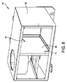
図8を参照すると、一実施形態では、フィルターアセンブリ58の板金構造体60は、有孔板金上部半体60a及び下部半体60bからなる。上述したように、鋼球の充填層62は、上部半体60a及び下部半体60b内に収容される。充填層62は、数百個の鋼球からなることができる。フィルターアセンブリ58は独立型であり、それにより、清掃するためにフラックス管理システム30のハウジング32から容易に取り除くことができる。
Referring to FIG. 8, in one embodiment, the
図9A〜図9Cは、フィルターアセンブリ58の球の充填層62を通してのフラックス収集の進行を示す。図9Aは、充填層62を通って流れるガス流路を示す。図9Bは、充填層62に取り付けられた液体膜を示す。図9Cは、充填層62から放出されている液滴の形成を示す。フィルターアセンブリ58から放出された大粒子は、ハウジング32の底壁の上に落下し、開口部76を通って収集容器36に向かって移動する。液化した汚染フラックスの収集容器への移動を容易にするために、ハウジング32の底壁を収集容器36に向かって傾斜させることができる。
9A-9C show the progress of flux collection through the spherical packed
フラックス管理システム30が提供されることにより、ウェーブはんだ機10を通るプロセスガス流パターンは以下のようになる。すなわち、1)汚染プロセスガスがトンネル18から抽出され、2)汚染プロセスガスは入口導管38からフラックス管理システム30に供給され、3)汚染プロセスガスは第1段階ユニット52を通って流れ、4)プロセスガスは、仕切り壁66の第1の開口部74を通って第1段階ユニット52から第2段階ユニット54まで流れ、5)プロセスガスは、第2段階ユニット54、特にフィルターアセンブリ58を通って流れ、6)ブロワユニット34は、およそ半分の処理済みガスが仕切り壁66の第2の開口部76を通って第1段階ユニット52に戻るように移動するのを促進し、7)処理済みガスの残りの半分(清浄なガス)はトンネル18に戻される。
By providing the
フラックス管理システムの変形としては、フラックス管理システムの熱交換器及びハウジングのサイズ及び形状を変化させ及び/又は変更することを挙げることができる。変形としては、充填層の鋼球のサイズ及び数並びに球の材料を変化させ及び/又は変更することを更に挙げることができ、球の材料は、球が温度に耐え、フラックスが付着する濡れ性の面を提供することができる限り、鋼以外のものとすることができる。他の変形としては、トンネル内に収容される処理済みガスの清浄サイクルを引き起こす方法、収集容器の交換の必要を警告する方法、及びシステムを通るガスの体積流量及び再循環率の変更を挙げることができる。 Variations of the flux management system can include changing and / or changing the size and shape of the heat exchanger and housing of the flux management system. Variations can further include changing and / or changing the size and number of steel balls in the packed bed and the material of the spheres, which can withstand the temperature and the flux adheres to the spheres. As long as the surface can be provided, it can be other than steel. Other variations include changing the volume flow rate and recirculation rate of the gas through the system, causing a cleaning cycle of the treated gas contained in the tunnel, warning the need for replacement of the collection vessel, and so on. Can do.
したがって、本開示の実施形態のフラックス管理システムは、ウェーブはんだ機で使用するのに有効であることが認められるべきである。フラックス管理システムは、ウェーブはんだ機のトンネルからフラックス汚染物質を除去するように構成されている。具体的には、ウェーブはんだトンネル内部の気化したフラックスは、除去されず含まれている場合、機械の内面に蓄積する可能性がある。トンネル内の過剰な蓄積により、機械部品及び/又は炉を通過する製品に対し、フラックスがそれらの上に滴下した場合、損傷をもたらす可能性がある。本開示の実施形態のこのフラックス管理システムにより、このフラックスの蓄積が低減し、それにより、清掃のための保守のコスト、機械のダウンタイムによる生産低下、及びフラックス汚染物質による製品の損傷が低減する。 Accordingly, it should be appreciated that the flux management system of embodiments of the present disclosure is effective for use with wave soldering machines. The flux management system is configured to remove flux contaminants from the tunnel of the wave solder machine. Specifically, the vaporized flux inside the wave solder tunnel may accumulate on the inner surface of the machine if it is included without being removed. Excessive accumulation in the tunnel can cause damage to the machine parts and / or products passing through the furnace if the flux drops on them. This flux management system of embodiments of the present disclosure reduces this flux buildup, thereby reducing maintenance costs for cleaning, reduced production due to machine downtime, and product damage due to flux contaminants. .
このように、本開示の少なくとも1つの実施形態のいくつかの態様について記載したが、当業者には様々な改変、変更及び改善が容易に想到することが理解されるべきである。こうした改変、変更及び改善は、本開示の一部であるように意図され、本開示の趣旨及び範囲内にあるように意図されている。したがって、上述した記載及び図面は単に例としてのものである。 Thus, while several aspects of at least one embodiment of the present disclosure have been described, it should be understood that various modifications, changes and improvements will readily occur to those skilled in the art. Such modifications, changes and improvements are intended to be part of this disclosure and are intended to be within the spirit and scope of this disclosure. Accordingly, the foregoing description and drawings are merely exemplary.
Claims (19)
前記電子基板の上にフラックスを塗布するように構成されたフラックス塗布ステーションと、
前記電子基板を加熱するように構成された予熱ステーションと、
前記電子基板に電子部品をはんだによって取り付けるように構成されたウェーブはんだ付けステーションと、
前記フラックス塗布ステーション、前記予熱ステーション及び前記ウェーブはんだ付けステーションを通過するトンネルを通して基板を輸送するように構成されたコンベアと、
前記トンネルから汚染物質を除去するように構成されたフラックス管理システムであって、前記トンネルからの蒸気流が該フラックス管理システムを通過し前記トンネルに戻るように、前記トンネルと流体連通しているフラックス管理システムと、
を備えるウェーブはんだ機。 A wave soldering machine configured to perform a wave soldering operation on an electronic board,
A flux application station configured to apply a flux on the electronic substrate;
A preheating station configured to heat the electronic substrate;
A wave soldering station configured to attach electronic components to the electronic board by solder;
A conveyor configured to transport the substrate through a tunnel passing through the flux application station, the preheating station and the wave soldering station;
A flux management system configured to remove contaminants from the tunnel, wherein the flux is in fluid communication with the tunnel such that a vapor stream from the tunnel passes through the flux management system and returns to the tunnel. A management system;
Equipped with wave soldering machine.
ウェーブはんだ機のトンネルから気化した汚染物質を含むガスを抽出することと、
前記ガスから汚染物質を除去するように構成されたフラックス管理システムに前記ガスを導くことと、
処理済みガスを生成するために前記フラックス管理システムによって前記ガスから汚染物質を除去することと、
前記処理済みガスを前記トンネル内に再度導入することと、
を含む方法。 A method for removing vaporized contaminants from inside a wave soldering machine,
Extracting vaporized contaminant gas from the tunnel of the wave soldering machine;
Directing the gas to a flux management system configured to remove contaminants from the gas;
Removing contaminants from the gas by the flux management system to produce a treated gas;
Reintroducing the treated gas into the tunnel;
Including methods.
Applications Claiming Priority (3)
| Application Number | Priority Date | Filing Date | Title |
|---|---|---|---|
| US14/162,198 | 2014-01-23 | ||
| US14/162,198 US9198300B2 (en) | 2014-01-23 | 2014-01-23 | Flux management system and method for a wave solder machine |
| PCT/US2014/066278 WO2015112243A1 (en) | 2014-01-23 | 2014-11-19 | Flux management system and method of contaminant removal for a wave solder machine |
Publications (2)
| Publication Number | Publication Date |
|---|---|
| JP2017505543A true JP2017505543A (en) | 2017-02-16 |
| JP6474824B2 JP6474824B2 (en) | 2019-02-27 |
Family
ID=52103000
Family Applications (1)
| Application Number | Title | Priority Date | Filing Date |
|---|---|---|---|
| JP2016548178A Active JP6474824B2 (en) | 2014-01-23 | 2014-11-19 | Flux management system for wave soldering machine and method for removing contaminants |
Country Status (7)
| Country | Link |
|---|---|
| US (1) | US9198300B2 (en) |
| EP (1) | EP3096915B1 (en) |
| JP (1) | JP6474824B2 (en) |
| KR (1) | KR102201124B1 (en) |
| CN (1) | CN106029276B (en) |
| TW (1) | TWI630973B (en) |
| WO (1) | WO2015112243A1 (en) |
Cited By (1)
| Publication number | Priority date | Publication date | Assignee | Title |
|---|---|---|---|---|
| JP2021523328A (en) * | 2018-05-09 | 2021-09-02 | タラノ・テクノロジー | Friction assembly for disc brake systems that can filter the gas phase resulting from lining friction |
Families Citing this family (15)
| Publication number | Priority date | Publication date | Assignee | Title |
|---|---|---|---|---|
| BR102012032031A2 (en) * | 2012-12-14 | 2014-09-09 | Air Liquide Brasil Ltda | PORTABLE EQUIPMENT FOR MONITORING AND CONTROL OF OXYGEN LEVEL IN REFUSION OVEN ATMOSPHERE |
| DE102014110720A1 (en) * | 2014-07-29 | 2016-02-04 | Illinois Tool Works Inc. | soldering module |
| US10029326B2 (en) | 2016-10-26 | 2018-07-24 | Illinois Tool Works Inc. | Wave soldering nozzle having automatic adjustable throat width |
| CN109316922A (en) * | 2017-12-14 | 2019-02-12 | 深圳市科延机电有限公司 | A kind of smokeless crest welder |
| US20190366460A1 (en) * | 2018-06-01 | 2019-12-05 | Progress Y&Y Corp. | Soldering apparatus and solder nozzle module thereof |
| US10780516B2 (en) | 2018-06-14 | 2020-09-22 | Illinois Tool Works Inc. | Wave solder nozzle with automated adjustable sliding plate to vary solder wave width |
| CN111054173A (en) * | 2018-10-17 | 2020-04-24 | 伊利诺斯工具制品有限公司 | Exhaust gas purification system |
| CN111054175B (en) * | 2018-10-17 | 2023-08-08 | 伊利诺斯工具制品有限公司 | Exhaust gas purifying device |
| CN111054174B (en) * | 2018-10-17 | 2023-08-08 | 伊利诺斯工具制品有限公司 | Exhaust gas purifying device |
| CN111240384B (en) * | 2020-02-28 | 2022-03-15 | 晶澳(邢台)太阳能有限公司 | Scaling powder adjusting device and method |
| US11389888B2 (en) | 2020-08-17 | 2022-07-19 | Illinois Tool Works Inc. | Wave solder nozzle with automated exit wing |
| EP4032648A1 (en) * | 2021-01-25 | 2022-07-27 | Infineon Technologies AG | Arrangement for forming a connection |
| CN113458641B (en) * | 2021-07-27 | 2023-07-14 | 中山市诺一五金制品有限公司 | Welding equipment for processing hardware workpiece |
| CN113649663A (en) * | 2021-08-31 | 2021-11-16 | 无锡鑫迈维电子设备有限公司 | Integrated selective crest welder |
| DE102021129131B4 (en) | 2021-11-09 | 2024-02-29 | Ersa Gmbh | Soldering system, in particular a reflow soldering system with fan units provided laterally next to a process channel |
Citations (18)
| Publication number | Priority date | Publication date | Assignee | Title |
|---|---|---|---|---|
| JPH0350789A (en) * | 1989-07-18 | 1991-03-05 | Murata Mfg Co Ltd | Soldering of electronic component device |
| JPH0494154U (en) * | 1991-01-09 | 1992-08-14 | ||
| JPH0573982U (en) * | 1991-04-26 | 1993-10-08 | 千住金属工業株式会社 | Outside air intrusion prevention device for soldering equipment |
| JPH05337677A (en) * | 1992-06-05 | 1993-12-21 | Tamura Seisakusho Co Ltd | Chamber for soldering and formation of its atmosphere |
| DE4242821A1 (en) * | 1992-12-17 | 1994-06-23 | Linde Ag | Cooling zone for soldering and similar heat treatment installations |
| JP3000420U (en) * | 1994-01-25 | 1994-08-09 | 日本電熱計器株式会社 | Atmosphere cooling device for soldering equipment |
| JPH0777346A (en) * | 1993-09-08 | 1995-03-20 | Nippon Dennetsu Keiki Kk | Fume discharging device in soldering device |
| JPH0721254U (en) * | 1993-09-07 | 1995-04-18 | 日本電池株式会社 | Flux recovery device |
| JPH07202405A (en) * | 1993-12-28 | 1995-08-04 | Nippon Dennetsu Keiki Kk | Soldering equipment |
| JPH0983125A (en) * | 1995-09-08 | 1997-03-28 | Ford Motor Co | Device for soldering part to circuit board |
| JPH09323022A (en) * | 1996-06-05 | 1997-12-16 | Nitsuku:Kk | Flux fume removing device |
| JP2001520462A (en) * | 1997-10-16 | 2001-10-30 | スピードライン・テクノロジーズ・インコーポレイテッド | Flux management system |
| JP2005523590A (en) * | 2002-04-17 | 2005-08-04 | スピードライン・テクノロジーズ・インコーポレーテッド | Filtering flux impurities |
| JP2007329376A (en) * | 2006-06-09 | 2007-12-20 | Tamura Furukawa Machinery:Kk | Reflow furnace |
| US20080295686A1 (en) * | 2007-05-30 | 2008-12-04 | Illinois Tool Works Inc. | Method and apparatus for removing contaminants from a reflow apparatus |
| US20080302861A1 (en) * | 2007-06-11 | 2008-12-11 | Szymanowski Richard A | Method and apparatus for wave soldering an electronic substrate |
| WO2009019773A1 (en) * | 2007-08-08 | 2009-02-12 | Senju Metal Industry Co., Ltd. | Reflow furnace |
| US20110315746A1 (en) * | 2010-06-28 | 2011-12-29 | Illinois Tool Works Inc. | Compression box for reflow oven heating and related method |
Family Cites Families (95)
| Publication number | Priority date | Publication date | Assignee | Title |
|---|---|---|---|---|
| US3482755A (en) * | 1967-09-25 | 1969-12-09 | Gen Electric | Automatic wave soldering machine |
| US3515330A (en) | 1968-01-30 | 1970-06-02 | Collins Radio Co | Continuous flow mass pin-to-board hot air soldering device |
| IT1030182B (en) * | 1975-02-19 | 1979-03-30 | Iemme Italia Spa | MELTED TIN WAVE WELDING MACHINE |
| US4079879A (en) | 1976-09-27 | 1978-03-21 | Carrier Corporation | Means for soldering aluminum joints |
| US4139143A (en) | 1977-11-25 | 1979-02-13 | Gte Automatic Electric Laboratories, Inc. | Wave solder machine |
| GB2016432B (en) * | 1978-03-17 | 1982-11-24 | Hoelter H | Metal oxide-coated coated silica fibres hot gas filter |
| US4478364A (en) * | 1980-11-07 | 1984-10-23 | Re-Al, Inc. | Method of mounting and cleaning electrical slide switch of flush through design |
| US4366351A (en) * | 1980-11-07 | 1982-12-28 | Re-Al, Inc. | Electrical slide switch of flush through design and method of mounting thereof |
| FR2538209A1 (en) | 1982-12-15 | 1984-06-22 | Europ Composants Electron | DEVICE FOR WELDING COMPONENT CONNECTIONS |
| US4533187A (en) * | 1983-01-06 | 1985-08-06 | Augat Inc. | Dual beam connector |
| US4775776A (en) | 1983-02-28 | 1988-10-04 | Electrovert Limited | Multi stage heater |
| FR2572970B1 (en) | 1984-11-15 | 1987-02-13 | Outillages Scient Lab | HEATING DEVICE FOR GENERATING A WELDING WAVE FOR A WAVE WELDING MACHINE |
| FR2587241B1 (en) * | 1985-05-28 | 1988-07-29 | Outillages Scient Laboratoir | CLEANING APPARATUS FOR ELECTRONIC COMPONENTS AND / OR PRECISION MECHANICAL PARTS |
| JPS62130770A (en) | 1985-11-30 | 1987-06-13 | Tamura Seisakusho Co Ltd | Reflow type soldering device |
| DE3735949A1 (en) | 1987-10-23 | 1989-05-03 | Ruhrgas Ag | METHOD AND DEVICE FOR CLEANING THE SURFACE OF OVEN ROLLS OF A ROLLER OVEN |
| US4881320A (en) * | 1987-10-26 | 1989-11-21 | Cts Corporation | Method of making vented seal for electronic components and an environmentally protected component |
| DE3737563A1 (en) | 1987-11-05 | 1989-05-18 | Ernst Hohnerlein | SOLDERING MACHINE |
| US4995411A (en) * | 1988-10-07 | 1991-02-26 | Hollis Automation, Inc. | Mass soldering system providing an improved fluid blast |
| US5023848A (en) * | 1989-05-15 | 1991-06-11 | Highes Aircraft Company | Solder wave dwell timer |
| JPH0338193A (en) * | 1989-07-04 | 1991-02-19 | Nec Corp | Feeding system for exchange |
| JPH0763839B2 (en) | 1989-10-06 | 1995-07-12 | 日立テクノエンジニアリング株式会社 | Reflow soldering equipment |
| US5121874A (en) | 1989-11-22 | 1992-06-16 | Electrovert Ltd. | Shield gas wave soldering |
| US5048746A (en) | 1989-12-08 | 1991-09-17 | Electrovert Ltd. | Tunnel for fluxless soldering |
| US5069380A (en) | 1990-06-13 | 1991-12-03 | Carlos Deambrosio | Inerted IR soldering system |
| US5230460A (en) | 1990-06-13 | 1993-07-27 | Electrovert Ltd. | High volume convection preheater for wave soldering |
| US5026295A (en) * | 1990-07-31 | 1991-06-25 | Molex Incorporated | Cover for an electrical connector |
| FR2670986B1 (en) * | 1990-12-20 | 1996-08-02 | Air Liquide | WELDING BATH INERTAGE DEVICE OF A WAVE WELDING MACHINE. |
| US5176307A (en) | 1991-02-22 | 1993-01-05 | Praxair Technology, Inc. | Wave soldering in a protective atmosphere enclosure over a solder pot |
| US5240169A (en) * | 1991-12-06 | 1993-08-31 | Electrovert Ltd. | Gas shrouded wave soldering with gas knife |
| IL100838A (en) * | 1992-01-31 | 1995-06-29 | Sasson Shay | Solder wave parameters analyzer |
| US5209389A (en) | 1992-02-26 | 1993-05-11 | Digital Equipment Corporation | Solder pump bushing seal |
| JP2731665B2 (en) | 1992-04-16 | 1998-03-25 | 日立テクノエンジニアリング株式会社 | Reflow soldering equipment |
| US5193735A (en) | 1992-07-13 | 1993-03-16 | Knight Electronics, Inc. | Solder reflow oven |
| NL9202279A (en) | 1992-07-29 | 1994-02-16 | Soltec Bv | Reflow soldering machine. |
| DE69327976T2 (en) | 1992-11-17 | 2000-11-02 | Matsushita Electric Ind Co Ltd | Method and device for reflow soldering |
| US5271545A (en) | 1993-03-31 | 1993-12-21 | Seco/Warwick Corporation | Muffle convection brazing/annealing system |
| US5440101A (en) | 1993-04-19 | 1995-08-08 | Research, Incorporated | Continuous oven with a plurality of heating zones |
| US5398865A (en) * | 1993-05-20 | 1995-03-21 | Electrovert Ltd. | Preparation of surfaces for solder joining |
| US5322209A (en) | 1993-07-19 | 1994-06-21 | General Motors Corporation | Aluminum heat exchanger brazing method and apparatus |
| US5347103A (en) | 1993-08-31 | 1994-09-13 | Btu International | Convection furnace using shimmed gas amplifier |
| US5364007A (en) | 1993-10-12 | 1994-11-15 | Air Products And Chemicals, Inc. | Inert gas delivery for reflow solder furnaces |
| US5379943A (en) | 1993-10-19 | 1995-01-10 | Ncr Corporation | Hot air circulation apparatus and method for wave soldering machines |
| US5524810A (en) | 1994-04-14 | 1996-06-11 | Sikama International, Inc. | Solder reflow processor |
| US5520320A (en) | 1994-04-22 | 1996-05-28 | Air Liquide America Corporation | Process for wave soldering components on a printed circuit board in a temperature controlled non-oxidizing atmosphere |
| US5611476C1 (en) | 1996-01-18 | 2002-02-26 | Btu Int | Solder reflow convection furnace employing flux handling and gas densification systems |
| US6145734A (en) | 1996-04-16 | 2000-11-14 | Matsushita Electric Industrial Co., Ltd. | Reflow method and reflow device |
| US5971246A (en) | 1996-05-08 | 1999-10-26 | Motorola, Inc. | Oven for reflowing circuit board assemblies and method therefor |
| US5941448A (en) * | 1996-06-07 | 1999-08-24 | L'air Liquide, Societe Anonyme Pour L'etude Et L'exploitation Des Procedes Georges Claude | Method for dry fluxing of metallic surfaces, before soldering or tinning, using an atmosphere which includes water vapor |
| FR2757650B1 (en) | 1996-12-20 | 1999-01-15 | Air Liquide | METHOD FOR SUPPLYING GAS TO A SPEAKER AND METHOD FOR REGULATING THE CONTENT OF A GIVEN ELEMENT IN THE ATMOSPHERE OF SUCH A SPEAKER |
| US5911486A (en) | 1997-02-26 | 1999-06-15 | Conceptronic, Inc. | Combination product cooling and flux management apparatus |
| JPH1154903A (en) | 1997-07-31 | 1999-02-26 | Fujitsu Ltd | Reflow soldering method and reflow furnace |
| NL1009214C2 (en) | 1998-05-19 | 1999-12-07 | Soltec Bv | Reflow oven. |
| US6446855B1 (en) | 1999-02-18 | 2002-09-10 | Speedline Technologies, Inc. | Compact reflow and cleaning apparatus |
| US6354481B1 (en) | 1999-02-18 | 2002-03-12 | Speedline Technologies, Inc. | Compact reflow and cleaning apparatus |
| JP3547377B2 (en) | 1999-11-01 | 2004-07-28 | 松下電器産業株式会社 | Solder jet device and soldering method |
| JP2001170767A (en) | 1999-12-10 | 2001-06-26 | Hitachi Ltd | Soldering apparatus |
| DE60140430D1 (en) | 2000-02-02 | 2009-12-24 | Btu Internat Inc | Modulares ofensystem |
| JP3578398B2 (en) | 2000-06-22 | 2004-10-20 | 古河スカイ株式会社 | Gas dispersion plate for film formation and method of manufacturing the same |
| JP3515058B2 (en) | 2000-08-14 | 2004-04-05 | 有限会社ヨコタテクニカ | Reflow soldering equipment |
| US6805282B2 (en) | 2000-09-26 | 2004-10-19 | Matsushita Electric Industrial Co., Ltd. | Flow soldering process and apparatus |
| JP3581828B2 (en) | 2000-12-25 | 2004-10-27 | 古河電気工業株式会社 | Heating furnace for soldering |
| US6386422B1 (en) | 2001-05-03 | 2002-05-14 | Asm Assembly Automation Limited | Solder reflow oven |
| GB2375057B (en) * | 2001-05-04 | 2003-10-01 | Philip Arthur Mullins | Air filter for extraction apparatus |
| GB2410202B (en) | 2001-05-30 | 2005-12-14 | Btu Int | Filtering apparatus |
| US6686566B1 (en) | 2002-03-15 | 2004-02-03 | Dave O. Corey | Infrared drying and curing system for circuit boards |
| CN100459827C (en) | 2002-05-16 | 2009-02-04 | 横田技术有限公司 | Reflow soldering device |
| US6780225B2 (en) * | 2002-05-24 | 2004-08-24 | Vitronics Soltec, Inc. | Reflow oven gas management system and method |
| US7380699B2 (en) | 2002-06-14 | 2008-06-03 | Vapour Phase Technology Aps | Method and apparatus for vapour phase soldering |
| US20130175323A1 (en) | 2002-07-01 | 2013-07-11 | Jian Zhang | Serial thermal linear processor arrangement |
| US6871776B2 (en) * | 2003-03-10 | 2005-03-29 | Trucco Horacio Andres | Manufacture of solid-solder-deposit PCB utilizing electrically heated wire mesh |
| CN2610608Y (en) | 2003-04-09 | 2004-04-07 | 东莞市科隆电子设备有限公司 | Preheating device of wave soldering |
| JP2005079466A (en) | 2003-09-02 | 2005-03-24 | Furukawa Electric Co Ltd:The | Reflow device having cooling mechanism and reflow furnace using the reflow device |
| TW200524500A (en) | 2004-01-07 | 2005-07-16 | Senju Metal Industry Co | Reflow furnace and hot-air blowing-type heater |
| TW200524496A (en) * | 2004-01-07 | 2005-07-16 | Senju Metal Industry | Reflow furnace |
| EP1732118B1 (en) | 2004-03-30 | 2011-05-11 | Tamura Corporation | Heater, reflow apparatus with such heater |
| JP4834559B2 (en) | 2005-01-17 | 2011-12-14 | 有限会社ヨコタテクニカ | Reflow furnace |
| EP1867424B1 (en) | 2005-02-07 | 2012-04-18 | Senju Metal Industry Co., Ltd. | Method for removing fume in reflow furnace and reflow furnace |
| US7407621B2 (en) * | 2005-03-07 | 2008-08-05 | Michael Keith | Mobile processing enclosure for preventing air pollution |
| DE102005010378B4 (en) * | 2005-03-07 | 2017-02-16 | Rehm Thermal Systems Gmbh | Apparatus and method for cleaning a process gas of a reflow soldering system |
| JP4319647B2 (en) | 2005-06-30 | 2009-08-26 | 株式会社タムラ古河マシナリー | Reflow furnace |
| JP3942623B2 (en) | 2005-12-12 | 2007-07-11 | 富士通テン株式会社 | Flat dip device and method of soldering flat dip device |
| US7653511B2 (en) | 2006-04-17 | 2010-01-26 | Kester, Inc. | Thermoconductimetric analyzer for soldering process improvement |
| US8091759B2 (en) | 2006-05-29 | 2012-01-10 | Kirsten Soldering Ag | Soldering machine comprising a soldering module and at least one soldering station that is mobile and exchangeable insertable into the soldering module |
| DE102007040037A1 (en) | 2007-08-24 | 2009-02-26 | Modine Manufacturing Co., Racine | Plant for soldering and process |
| US7951244B2 (en) | 2008-01-11 | 2011-05-31 | Illinois Tool Works Inc. | Liquid cleaning apparatus for cleaning printed circuit boards |
| CN201227707Y (en) | 2008-02-03 | 2009-04-29 | 日东电子科技(深圳)有限公司 | Transverse refluxing mixed gas heating apparatus |
| US7708183B2 (en) | 2008-03-28 | 2010-05-04 | Illinois Tool Works Inc. | Reflow solder oven with cooling diffuser |
| CN101648304A (en) | 2009-07-09 | 2010-02-17 | 维多利绍德机械科技(苏州)有限公司 | Return air device for reflow soldering |
| US8146792B2 (en) * | 2010-03-16 | 2012-04-03 | Flextronics Ap, Llc | Solder return for wave solder nozzle |
| GB2479553B (en) | 2010-04-14 | 2012-07-18 | Afc Holcroft | Aluminium brazing |
| CN201824037U (en) | 2010-09-16 | 2011-05-11 | 深圳市诺斯达科技有限公司 | Preheating device of wave soldering machine |
| US8579182B2 (en) * | 2011-06-17 | 2013-11-12 | Air Products And Chemicals, Inc. | Method for providing an inerting gas during soldering |
| JP5459294B2 (en) | 2011-11-15 | 2014-04-02 | 株式会社デンソー | Reflow device |
| US20140027495A1 (en) * | 2012-04-18 | 2014-01-30 | Air Products And Chemicals Inc. | Apparatus And Method For Providing An Inerting Gas During Soldering |
| CN103769713B (en) | 2012-10-19 | 2016-02-03 | 台达电子电源(东莞)有限公司 | Pre-thermal module, the preheating zone using this pre-thermal module and preheating section |
-
2014
- 2014-01-23 US US14/162,198 patent/US9198300B2/en active Active
- 2014-11-19 JP JP2016548178A patent/JP6474824B2/en active Active
- 2014-11-19 CN CN201480076234.2A patent/CN106029276B/en active Active
- 2014-11-19 KR KR1020167022727A patent/KR102201124B1/en active IP Right Grant
- 2014-11-19 WO PCT/US2014/066278 patent/WO2015112243A1/en active Application Filing
- 2014-11-19 EP EP14812677.4A patent/EP3096915B1/en active Active
- 2014-12-03 TW TW103142027A patent/TWI630973B/en not_active IP Right Cessation
Patent Citations (18)
| Publication number | Priority date | Publication date | Assignee | Title |
|---|---|---|---|---|
| JPH0350789A (en) * | 1989-07-18 | 1991-03-05 | Murata Mfg Co Ltd | Soldering of electronic component device |
| JPH0494154U (en) * | 1991-01-09 | 1992-08-14 | ||
| JPH0573982U (en) * | 1991-04-26 | 1993-10-08 | 千住金属工業株式会社 | Outside air intrusion prevention device for soldering equipment |
| JPH05337677A (en) * | 1992-06-05 | 1993-12-21 | Tamura Seisakusho Co Ltd | Chamber for soldering and formation of its atmosphere |
| DE4242821A1 (en) * | 1992-12-17 | 1994-06-23 | Linde Ag | Cooling zone for soldering and similar heat treatment installations |
| JPH0721254U (en) * | 1993-09-07 | 1995-04-18 | 日本電池株式会社 | Flux recovery device |
| JPH0777346A (en) * | 1993-09-08 | 1995-03-20 | Nippon Dennetsu Keiki Kk | Fume discharging device in soldering device |
| JPH07202405A (en) * | 1993-12-28 | 1995-08-04 | Nippon Dennetsu Keiki Kk | Soldering equipment |
| JP3000420U (en) * | 1994-01-25 | 1994-08-09 | 日本電熱計器株式会社 | Atmosphere cooling device for soldering equipment |
| JPH0983125A (en) * | 1995-09-08 | 1997-03-28 | Ford Motor Co | Device for soldering part to circuit board |
| JPH09323022A (en) * | 1996-06-05 | 1997-12-16 | Nitsuku:Kk | Flux fume removing device |
| JP2001520462A (en) * | 1997-10-16 | 2001-10-30 | スピードライン・テクノロジーズ・インコーポレイテッド | Flux management system |
| JP2005523590A (en) * | 2002-04-17 | 2005-08-04 | スピードライン・テクノロジーズ・インコーポレーテッド | Filtering flux impurities |
| JP2007329376A (en) * | 2006-06-09 | 2007-12-20 | Tamura Furukawa Machinery:Kk | Reflow furnace |
| US20080295686A1 (en) * | 2007-05-30 | 2008-12-04 | Illinois Tool Works Inc. | Method and apparatus for removing contaminants from a reflow apparatus |
| US20080302861A1 (en) * | 2007-06-11 | 2008-12-11 | Szymanowski Richard A | Method and apparatus for wave soldering an electronic substrate |
| WO2009019773A1 (en) * | 2007-08-08 | 2009-02-12 | Senju Metal Industry Co., Ltd. | Reflow furnace |
| US20110315746A1 (en) * | 2010-06-28 | 2011-12-29 | Illinois Tool Works Inc. | Compression box for reflow oven heating and related method |
Cited By (3)
| Publication number | Priority date | Publication date | Assignee | Title |
|---|---|---|---|---|
| JP2021523328A (en) * | 2018-05-09 | 2021-09-02 | タラノ・テクノロジー | Friction assembly for disc brake systems that can filter the gas phase resulting from lining friction |
| JP7379777B2 (en) | 2018-05-09 | 2023-11-15 | タラノ・テクノロジーズ | Friction assembly for disc brake systems capable of filtering the gas phase resulting from lining friction |
| US11940025B2 (en) | 2018-05-09 | 2024-03-26 | Tallano Technologie | Friction assembly for a disc brake system able to filter a gaseous phase resulting from the friction of a lining |
Also Published As
| Publication number | Publication date |
|---|---|
| TWI630973B (en) | 2018-08-01 |
| WO2015112243A1 (en) | 2015-07-30 |
| KR102201124B1 (en) | 2021-01-08 |
| US9198300B2 (en) | 2015-11-24 |
| EP3096915B1 (en) | 2020-01-08 |
| JP6474824B2 (en) | 2019-02-27 |
| TW201529217A (en) | 2015-08-01 |
| KR20160107337A (en) | 2016-09-13 |
| CN106029276B (en) | 2019-03-01 |
| CN106029276A (en) | 2016-10-12 |
| EP3096915A1 (en) | 2016-11-30 |
| US20150208515A1 (en) | 2015-07-23 |
Similar Documents
| Publication | Publication Date | Title |
|---|---|---|
| JP6474824B2 (en) | Flux management system for wave soldering machine and method for removing contaminants | |
| AU2008260343B2 (en) | Method and apparatus for removing contaminants from a reflow apparatus | |
| CN100548555C (en) | The method of removing and the reflow ovens of the smog of reflow ovens | |
| JP4393576B1 (en) | Disassembly method of electrical equipment | |
| US8518157B2 (en) | Device and method for purifying a process gas in a reflow soldering system | |
| EP3253522B1 (en) | Reflow soldering oven with at least one gas purification system comprising a catalyst unit, and method using such reflow soldering oven | |
| US9744612B2 (en) | Flux recovery device and soldering device | |
| JP7189912B2 (en) | Gas purifying device and transport heating device | |
| JP4082462B1 (en) | Reflow furnace | |
| JP2005523590A (en) | Filtering flux impurities | |
| JP2007053158A (en) | Reflow soldering device and flux removing device | |
| JPH05261528A (en) | Vapor reflow soldering device | |
| JP2005500166A (en) | Method and apparatus for removing a water-soluble mold core | |
| JP3597878B2 (en) | Atmosphere furnace exhaust gas suction device | |
| JP2007109841A (en) | Method of cleaning reflow-soldering device, and reflow-soldering device | |
| JP2004195476A (en) | Cooling device for soldering, and reflow device | |
| KR100659770B1 (en) | Exhaust system for reflow soldering apparatus | |
| CN111054175A (en) | Exhaust gas purification device | |
| JP2011082282A (en) | Reflow apparatus | |
| JP2004285403A (en) | Cooling unit | |
| JPH088528A (en) | Vapor reflow soldering device | |
| JP2020163268A (en) | Dust collection system and heat exchange device | |
| CN110090514A (en) | Gas cleaning plant, method for gas purification and delivery heating device | |
| CN111054173A (en) | Exhaust gas purification system | |
| JPH11253853A (en) | Recovering device for water soluble coating |
Legal Events
| Date | Code | Title | Description |
|---|---|---|---|
| A621 | Written request for application examination |
Free format text: JAPANESE INTERMEDIATE CODE: A621 Effective date: 20170913 |
|
| A131 | Notification of reasons for refusal |
Free format text: JAPANESE INTERMEDIATE CODE: A131 Effective date: 20180911 |
|
| A521 | Request for written amendment filed |
Free format text: JAPANESE INTERMEDIATE CODE: A523 Effective date: 20181026 |
|
| TRDD | Decision of grant or rejection written | ||
| A01 | Written decision to grant a patent or to grant a registration (utility model) |
Free format text: JAPANESE INTERMEDIATE CODE: A01 Effective date: 20190108 |
|
| A61 | First payment of annual fees (during grant procedure) |
Free format text: JAPANESE INTERMEDIATE CODE: A61 Effective date: 20190130 |
|
| R150 | Certificate of patent or registration of utility model |
Ref document number: 6474824 Country of ref document: JP Free format text: JAPANESE INTERMEDIATE CODE: R150 |
|
| R250 | Receipt of annual fees |
Free format text: JAPANESE INTERMEDIATE CODE: R250 |
|
| R250 | Receipt of annual fees |
Free format text: JAPANESE INTERMEDIATE CODE: R250 |
|
| R250 | Receipt of annual fees |
Free format text: JAPANESE INTERMEDIATE CODE: R250 |