JP2017503732A - Self-guided container straddle carrier device with movable sensor assembly - Google Patents
Self-guided container straddle carrier device with movable sensor assembly Download PDFInfo
- Publication number
- JP2017503732A JP2017503732A JP2016547149A JP2016547149A JP2017503732A JP 2017503732 A JP2017503732 A JP 2017503732A JP 2016547149 A JP2016547149 A JP 2016547149A JP 2016547149 A JP2016547149 A JP 2016547149A JP 2017503732 A JP2017503732 A JP 2017503732A
- Authority
- JP
- Japan
- Prior art keywords
- carrier device
- straddle carrier
- sensor assembly
- container
- operating position
- Prior art date
- Legal status (The legal status is an assumption and is not a legal conclusion. Google has not performed a legal analysis and makes no representation as to the accuracy of the status listed.)
- Ceased
Links
Images

Classifications
-
- B—PERFORMING OPERATIONS; TRANSPORTING
- B66—HOISTING; LIFTING; HAULING
- B66C—CRANES; LOAD-ENGAGING ELEMENTS OR DEVICES FOR CRANES, CAPSTANS, WINCHES, OR TACKLES
- B66C19/00—Cranes comprising trolleys or crabs running on fixed or movable bridges or gantries
- B66C19/007—Cranes comprising trolleys or crabs running on fixed or movable bridges or gantries for containers
-
- B—PERFORMING OPERATIONS; TRANSPORTING
- B66—HOISTING; LIFTING; HAULING
- B66C—CRANES; LOAD-ENGAGING ELEMENTS OR DEVICES FOR CRANES, CAPSTANS, WINCHES, OR TACKLES
- B66C13/00—Other constructional features or details
- B66C13/18—Control systems or devices
-
- B—PERFORMING OPERATIONS; TRANSPORTING
- B66—HOISTING; LIFTING; HAULING
- B66C—CRANES; LOAD-ENGAGING ELEMENTS OR DEVICES FOR CRANES, CAPSTANS, WINCHES, OR TACKLES
- B66C13/00—Other constructional features or details
- B66C13/18—Control systems or devices
- B66C13/48—Automatic control of crane drives for producing a single or repeated working cycle; Programme control
-
- G—PHYSICS
- G05—CONTROLLING; REGULATING
- G05D—SYSTEMS FOR CONTROLLING OR REGULATING NON-ELECTRIC VARIABLES
- G05D1/00—Control of position, course or altitude of land, water, air, or space vehicles, e.g. automatic pilot
- G05D1/02—Control of position or course in two dimensions
- G05D1/021—Control of position or course in two dimensions specially adapted to land vehicles
Abstract
本発明は、ガントリ昇降装置(1)をナビゲートするためのセンサアセンブリ(12)を含み、かつガントリ昇降装置(1)によって運搬されるコンテナ(8)のための空間(17)を含む、コンテナ(8)、特にISOコンテナを移送するための、ガントリ昇降装置(1) に関する。改善された無人ガントリ昇降装置(1)を作製するために、本発明に係るセンサアセンブリ(12)は作動位置では、運搬されたコンテナ(8)のための空間(17)の下でガントリ昇降装置(1)に配設され、作動位置から、センサアセンブリ(12)が運搬されるコンテナ(8)の荷取りおよび/または荷下ろしを可能にするアイドル位置に移動することができる。【選択図】 図1The present invention includes a sensor assembly (12) for navigating a gantry lifting device (1) and a space (17) for a container (8) carried by the gantry lifting device (1) (8) In particular, the present invention relates to a gantry lifting device (1) for transferring an ISO container. In order to make an improved unmanned gantry lifting device (1), the sensor assembly (12) according to the present invention is in the operating position under the space (17) for the transported container (8). Arranged at (1) and can be moved from an operating position to an idle position that allows the container (8) to which the sensor assembly (12) is transported to be unloaded and / or unloaded. [Selection] Figure 1
Description
本発明は、ストラドルキャリア装置のナビゲーションのためのセンサアセンブリを有し、かつストラドルキャリア装置によって運搬されるコンテナ用の空間を有する、コンテナ、特にISOコンテナを荷役するためのストラドルキャリア装置に関する。 The present invention relates to a straddle carrier device for handling containers, in particular ISO containers, having a sensor assembly for navigation of the straddle carrier device and having a space for containers carried by the straddle carrier device.
このタイプのストラドルキャリア装置は、ストラドルキャリアスタッキングワゴン、ガントリスタッキングワゴン、ストラドルキャリア、バンキャリア、シャトルキャリア、またはランナーとも呼ばれており、一般的に知られている。それらは、ターミナル、特に港湾ターミナルまたは道路と鉄道との間の複合輸送用ターミナルにおけるISO規格コンテナ用の専用荷役装置である。スプレッダと呼ばれる昇降装置および荷受け手段の助けを借りて、ストラドルキャリア装置はコンテナを吊り上げ、かつ移送後に目標位置にコンテナを降ろすことができる。ゴムタイヤを備えた床拘束ストラドルキャリア装置はクモ脚構造を含むので、地面にまたは別のコンテナの上に載置されているコンテナの上を走行することができ、加えて、施工によっては、その際に、吊り上げられたコンテナを移送することもできる。施工高さに応じて、ストラドルキャリア装置は例えば四段積み(1 over 3)装置、三段積み(1 over 2)装置等と呼ばれる。四段積み装置は、三段に積み重ねられたコンテナ上にコンテナを降ろし、三段に積み重ねられたコンテナの一つを荷取りし、あるいは荷取りされたコンテナと共に三段に積み重ねられたコンテナ上を走行することができる。これに関連して、ISOコンテナは、物品の国際輸送に使用される規格化された大容量または海上貨物コンテナと理解される。最も幅広く使用されているのは、幅が8フィート、長さが20、40、または45フィートのISOコンテナである。ストラドルキャリア装置は自由に走行することができ、通常、ディーゼル電気駆動装置、流体式ディーゼル駆動装置、または全電気駆動装置を有する。現在使用されているストラドルキャリア装置は主に手動で制御されており、この目的のために運転室が適宜設けられる。 This type of straddle carrier device, also called a straddle carrier stacking wagon, gantry stacking wagon, straddle carrier, van carrier, shuttle carrier, or runner, is generally known. They are dedicated handling equipment for ISO standard containers in terminals, especially port terminals or terminals for combined transportation between roads and railways. With the help of a lifting device called a spreader and load receiving means, the straddle carrier device can lift the container and lower it to the target position after transfer. The floor-restrained straddle carrier device with rubber tires includes a spider leg structure so that it can travel on a container placed on the ground or on another container, and in addition, depending on the construction, In addition, the lifted container can be transported. Depending on the construction height, the straddle carrier device is called, for example, a four-stack device (1 over 3) device, a three-stack device (1 over 2) device or the like. A four-stage stacking device unloads a container on a container stacked in three stages, unloads one of the containers stacked in three stages, or moves on a container stacked in three stages together with the unloaded containers. Can travel. In this context, an ISO container is understood as a standardized large capacity or sea freight container used for the international transport of goods. The most widely used are ISO containers that are 8 feet wide and 20, 40, or 45 feet long. The straddle carrier device can run freely and usually has a diesel electric drive, a fluid diesel drive, or an all-electric drive. Currently used straddle carrier devices are mainly controlled manually, and a cab is appropriately provided for this purpose.
自動制御されるストラドルキャリア装置も知られている。欧州特許第2096074号明細書には、ナビゲーションのために、衛星ナビゲーションと経路測定によってサポートされる局所的無線測位法との組合せを使用する、ストラドルキャリア装置が記載されている。コンテナまたはコンテナスタックの上を走行する領域では、ストラドルキャリア装置を自動的に操縦するためのレーザスキャナが追加的に使用される。このタイプのナビゲーションは、ストラドルキャリア装置が走行する地面にトランスポンダまたは磁石の形のマーキング要素が埋め込まれないので、いわゆるトランスポンダまたはグリッドポイントナビゲーションより有利なはずである。マーキング要素は大抵の場合、受動トランスポンダまたは磁石である。マーキング要素は港湾およびターミナル地域全域の走行経路領域の地表面全体に分配される。このトランスポンダまたはグリッドポイントナビゲーションは、FROG(Free Ranging On Grid)法とも呼ばれる。このFROG法は、自動化床拘束型ゴムタイヤ付き誘導車両に関連してドイツ特許出願公開第102006044645号に詳細に記載されている。マーキング要素に沿って誘導車両をナビゲートするために、アンテナおよび/または磁界センサの形のセンサアセンブリが誘導車両に配置される。センサアセンブリを用いて、走行車線に埋め込まれたマーキング要素は、通過時にそれらの設計に応じて認識されまたは読み取られる。この目的のために、誘導車両には広幅の平板状センサアセンブリが装着され、それらは誘導車両の前部および後部で地面の真上にそれと平行に取り付けられる。センサアセンブリは走行方向に対し直角に、誘導車両の車幅全体にわたって延び、したがって二つ以上のマーキング要素を同時に検知する。センサアセンブリを介して得られた情報は次いで、車両をナビゲートするために使用される。マーキング要素は一定のグリッドパターンで地面に埋め込まれるので、このナビゲーション方法は、グリッドポイントナビゲーションとも呼ばれる。 Automatic straddle carrier devices are also known. EP 2096074 describes a straddle carrier device that uses a combination of satellite navigation and local radio positioning methods supported by route measurement for navigation. In areas that run over containers or container stacks, laser scanners are additionally used for automatically maneuvering the straddle carrier device. This type of navigation should be advantageous over so-called transponder or grid point navigation, since marking elements in the form of transponders or magnets are not embedded in the ground on which the straddle carrier device travels. The marking element is most often a passive transponder or magnet. The marking elements are distributed over the ground surface of the travel route area throughout the port and terminal areas. This transponder or grid point navigation is also called FROG (Free Ranging On Grid) method. This FROG method is described in detail in German Offenlegungsschrift 102006044645 in connection with a guided vehicle with automated floor-restrained rubber tires. In order to navigate the guided vehicle along the marking element, a sensor assembly in the form of an antenna and / or a magnetic field sensor is arranged on the guided vehicle. With the sensor assembly, marking elements embedded in the driving lane are recognized or read according to their design when passing. For this purpose, the guide vehicle is fitted with a wide flat sensor assembly, which is mounted in parallel to and directly above the ground at the front and rear of the guide vehicle. The sensor assembly extends at right angles to the direction of travel and spans the entire vehicle width of the guided vehicle and thus senses two or more marking elements simultaneously. The information obtained via the sensor assembly is then used to navigate the vehicle. Since the marking elements are embedded in the ground with a fixed grid pattern, this navigation method is also called grid point navigation.
ドイツ特許出願公開第10323641号からフォークリフト車は知られており、そのセンサは、荷受け手段の荷物の下の領域に移動可能に配置される。 German Patent Application No. 10323641 discloses a forklift vehicle whose sensor is movably arranged in the region under the load of the load receiving means.
したがって、本発明の目的は、グリッドポイントナビゲーション用の改善された無人ストラドルキャリア装置を作製することである。 Accordingly, it is an object of the present invention to create an improved unmanned straddle carrier device for grid point navigation.
この目的は、請求項1の特徴を有する無人ストラドルキャリア装置により達成される。本発明の有利な実施形態は、請求項2ないし10に記載される。
This object is achieved by an unmanned straddle carrier device having the features of claim 1. Advantageous embodiments of the invention are described in
本発明によれば、ストラドルキャリア装置のナビゲーション用のセンサアセンブリを有し、かつストラドルキャリア装置によって運搬されるコンテナ用の空間を有する、コンテナ、特にISOコンテナを荷役するためのストラドルキャリア装置の場合、センサアセンブリは、作動位置ではストラドルキャリア装置の運搬されるコンテナ用の空間の下に配置され、かつ作動位置から、センサアセンブリが運搬されるコンテナの荷取りおよび/または荷降ろしを可能にする非作動位置へ移動することができるので、改善が達成される。 According to the invention, in the case of a straddle carrier device for handling a container, in particular an ISO container, having a sensor assembly for navigation of the straddle carrier device and having a space for a container carried by the straddle carrier device. The sensor assembly is located below the space for the transported container of the straddle carrier device in the actuated position and from the actuated position, the non-actuated to allow unloading and / or unloading of the container in which the sensor assembly is transported An improvement is achieved because it can be moved into position.
ストラドルキャリア装置の荷役動作は、センサアセンブリがストラドルキャリア装置内の運搬されるコンテナの下の空間から非作動位置に移動することによって妨害されない。コンテナの荷取りまたは荷下ろしの後に、センサアセンブリが地面に埋め込まれたマーキング要素の真上の作動位置に移動すると、グリッドポイントナビゲーションによるストラドルキャリア装置の自動ナビゲーションが可能になる。 The handling operation of the straddle carrier device is not hindered by the sensor assembly moving from the space under the transported container in the straddle carrier device to an inoperative position. After the container has been unloaded or unloaded, automatic navigation of the straddle carrier device by grid point navigation is possible when the sensor assembly is moved to an operating position directly above the marking element embedded in the ground.
本発明によって、コンテナターミナルですでにグリッドポイントナビゲーションを用いてナビゲートされている自動誘導車両と共に、統合ネットワークで自動ストラドルキャリア装置を使用することも容易に可能になる。これは、ストラドルキャリア装置に対し対応する適応を施すことによって、かつターミナルの地面に対する変更無く、達成することができる。本発明に係るセンサアセンブリは単独で、ストラドルキャリア装置が、地面に近接した車両幅のセンサ装置にも拘わらず妨害されずに、コンテナ上を走行することを可能にする。本発明に係る車両幅のセンサアセンブリは、それ無しではマーキング要素のグリッドパターン密度を増大させることが必要になるという問題を解決する。 The present invention also facilitates the use of an automated straddle carrier device in an integrated network with an automated guided vehicle already navigated using grid point navigation at a container terminal. This can be achieved by applying a corresponding adaptation to the straddle carrier device and without any changes to the ground of the terminal. The sensor assembly according to the present invention alone enables the straddle carrier device to travel on the container without being disturbed despite the vehicle width sensor device close to the ground. The vehicle width sensor assembly according to the present invention solves the problem that without it it would be necessary to increase the grid pattern density of the marking elements.
構造的に単純な方法で、ストラドルキャリア装置は、ストラドルキャリア装置がコンテナ上を走行できるように設計された構造隙間を含むように構成され、かつセンサアセンブリは、非作動位置でセンサアセンブリが構造隙間の外に配置されるように設計される。構造隙間は、地面に置かれ、まだ荷取りされていないか、あるいはすでに荷下ろしされたコンテナ上をストラドルキャリア装置が長さ方向に衝突が起きないように移動できるようにするために必要な空間を包囲し、コンテナは構造隙間内に配置され、構造隙間を通り抜ける。 In a structurally simple manner, the straddle carrier device is configured to include a structural gap designed to allow the straddle carrier device to travel over the container, and the sensor assembly is in a non-actuated position where the sensor assembly is Designed to be placed outside. The structural gap is the space required to allow the straddle carrier device to move on the ground, on a container that has not yet been unloaded, or has already been unloaded, without causing a collision in the longitudinal direction. The container is disposed in the structural gap and passes through the structural gap.
ストラドルキャリア装置は自動的にナビゲートされ、センサアセンブリはグリッドポイントナビゲーションの原理に従って動作し、かつセンサアセンブリは作動位置で、ストラドルキャリア装置がその上を走行する地面に近接して、ストラドルキャリア装置に配置されるように、有利に構成される。地面に対して10から40cmの読取り距離を維持することが好ましい。 The straddle carrier device is automatically navigated, the sensor assembly operates in accordance with the principles of grid point navigation, and the sensor assembly is in the actuated position and close to the ground on which the straddle carrier device travels. It is advantageously configured to be arranged. It is preferable to maintain a reading distance of 10 to 40 cm relative to the ground.
グリッドパターンに配置された利用可能なマーキング要素を使用し、かつマーキング要素のグリッドパターン密度の増大を回避することを可能にするために、センサアセンブリは作動位置で、ストラドルキャリア装置の走行方向に対し直角に配置されるようになっている。 In order to be able to use the available marking elements arranged in the grid pattern and to avoid increasing the grid pattern density of the marking elements, the sensor assembly is in the operating position relative to the direction of travel of the straddle carrier device. They are arranged at right angles.
ストラドルキャリア装置を両走行方向に容易に自動誘導することができるようにするために、少なくとも二つのセンサアセンブリがストラドルキャリア装置に配置され、そのうちの一つのセンサアセンブリは、走行方向に見て、ストラドルキャリア装置の前部に配置され、一つのセンサアセンブリはストラドルキャリア装置の後部に配置される。 In order to be able to easily guide the straddle carrier device in both directions of travel, at least two sensor assemblies are arranged on the straddle carrier device, one of which is seen in the direction of travel, Located at the front of the carrier device, one sensor assembly is located at the rear of the straddle carrier device.
さらに、ストラドルキャリア装置は、運搬されるコンテナ用の空間に隣接し、かつストラドルキャリア装置の走行方向に向けられた、二つの相互に平行な駆動歯車支持体を有し、かつセンサアセンブリが作動位置で、地面に近接する二つの駆動歯車支持体の間の領域にまたがるようにすることが、構造的に有利である。 In addition, the straddle carrier device has two mutually parallel drive gear supports adjacent to the space for the container to be transported and oriented in the direction of travel of the straddle carrier device, and the sensor assembly is in the operating position. Thus, it is structurally advantageous to straddle the region between the two drive gear supports close to the ground.
センサアセンブリは、駆動歯車支持体に配置されたスピンドルを中心に、作動位置から非作動位置へ枢動できるようにすることが構造的に有利である。これに関連して、地面と平行に枢動することのできる側方センサアセンブリ、および上方に枢動できるセンサアセンブリの可能性が存在する。それに対応して、スピンドルは垂直方向にまたは走行方向に向けられ、センサアセンブリは非作動位置で垂直方向に、または駆動歯車支持体の長手方向に向けられる。それはまた、スピンドルが垂直方向に、または走行方向に向けられ、センサアセンブリが非作動位置で垂直方向に、または駆動歯車支持体の長手方向に向けられるという有利な結果をもたらす。 It is structurally advantageous for the sensor assembly to be pivotable from an actuated position to a non-actuated position about a spindle disposed on the drive gear support. In this context, there is the possibility of a side sensor assembly that can pivot parallel to the ground and a sensor assembly that can pivot upward. Correspondingly, the spindle is oriented vertically or in the direction of travel and the sensor assembly is oriented vertically in the inoperative position or in the longitudinal direction of the drive gear support. It also has the advantageous result that the spindle is oriented vertically or in the direction of travel and the sensor assembly is oriented vertically in the inoperative position or in the longitudinal direction of the drive gear support.
センサアセンブリはいずれの場合も全体として短くなるので、非作動位置に枢動するかまたは折り畳まれるプロセスを簡単にすることができるように、有利な方法で、センサアセンブリは真ん中で二つの別個の部品に分割される。その場合、センサアセンブリの部品のための受容空間は、それに対応して小さくなるように選択することもできる。 The sensor assembly is shortened as a whole in any case, so that in an advantageous manner the sensor assembly has two separate parts in the middle so that the process of pivoting or folding into the non-actuated position can be simplified. It is divided into. In that case, the receiving space for the parts of the sensor assembly can also be selected to be correspondingly small.
センサアセンブリは、作動駆動装置を介して自動制御により移動することができるように構成することが有利である。 The sensor assembly is advantageously configured such that it can be moved by automatic control via an actuating drive.
本発明の二つの例示的実施形態について、以下の図面を用いて説明する。 Two exemplary embodiments of the invention will be described with reference to the following drawings.
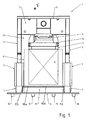
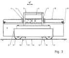
図1は、コンテナ荷役作業でグリッドポイントナビゲーションの助けを借りて自動的に誘導されるストラドルキャリア装置1に適用される第一実施形態を用いて、本発明の原理の概略図を示す。図2および図3は、図1を下および横から見た図を示す。ストラドルキャリア装置1の第一実施形態について、以下で図1ないし図3の助けを借りて説明する。 FIG. 1 shows a schematic diagram of the principles of the present invention using a first embodiment applied to a straddle carrier device 1 that is automatically guided with the aid of grid point navigation in container handling operations. 2 and 3 show a view of FIG. 1 from below and from the side. A first embodiment of the straddle carrier device 1 will be described below with the help of FIGS.
ストラドルキャリア装置1は、ストラドルキャリア装置1の長手方向に向けられた、相互に平行な二つの駆動歯車支持体2を有し、そこに操舵自在車輪3が取り付けられるが、そのうちの前輪3だけが示されている。駆動歯車支持体2の片側にそれぞれ二つずつ配置される車輪3はゴムタイヤ付きであり、好ましくは港湾のコンテナターミナルの地面4上を走行する。車輪3は、従来の方法で仮想的矩形の隅に配置される。基本的に、技術上の理由から必要ならば、五つ以上のゴムタイヤ付き車輪3を設けることも可能である。しかし、これは次いでストラドルキャリア装置1全体の複雑さの増大を伴い、したがって駆動および操舵の領域でより複雑な技術を使用しなければならない。自動誘導式ストラドルキャリア装置1の場合、操舵される車輪3の数が増加するため、ナビゲーションもより複雑になる。支柱5は二つの駆動歯車支持体2の各々の前部および後部から延び、したがって全部で四つの支柱5が垂直方向上方に延びてガントリ7を形成し、その上に機械プラットホーム6が配置され、支柱5を接続する。コンテナ8用の昇降装置9はガントリ7の機械プラットホーム6上に配置され、この昇降装置に対し、スプレッダ10と呼ばれるコンテナ8用の荷取り手段が、コンテナを昇降させることができるように接続される。荷物をピックアップするために、スプレッダ10はコンテナ8の四隅の金具11に係止することができる。空間17はガントリ7および駆動歯車支持体2によって囲まれ、この空間内に、ストラドルキャリア装置1によって運搬されたコンテナ8は、スプレッダ10によって荷取りされた後、かつ昇降装置9によって搬送位置内に持ち上げられた後で、すなわち依然として運搬中に、配置される。
The straddle carrier device 1 has two drive gear supports 2 which are oriented in the longitudinal direction of the straddle carrier device 1 and are parallel to each other, to which a
ストラドルキャリア装置1の下方領域には、センサアセンブリ12が駆動歯車支持体2上に配置され、水平方向にまたは地面4と平行に向けられ、その長手方向の広がりはストラドルキャリア装置1の走行方向Fに対して直角に、ほぼその全幅にわたって延びる。センサアセンブリ12は、二つの駆動歯車支持体2の間で少なくとも空間17の幅を網羅する。これは、コンテナ8が空間17内に位置している場合、すなわちもはや地面4に降ろされていない場合であり、センサアセンブリ12は空間17の下の図1に示す作動位置内にある。換言すると、センサアセンブリ12は、センサアセンブリ12が作動位置に着いているときに空間17の底部を画定する。センサアセンブリ12は、ストラドルキャリア装置1がコンテナ8無しで空で走行しているときでも、作動位置にある。
In the lower region of the straddle carrier device 1, a
ストラドルキャリア装置1がコンテナ8の荷取りおよび/または荷下ろしを行うことができるようにするために、センサアセンブリ12は作動位置から、運搬されるコンテナ8の荷取りおよび/または荷下ろしのために必要なコンテナ8の移動をセンサアセンブリ12が可能にする非作動位置へ移動される。図1で、破線は、非作動位置のときにセンサアセンブリ12がそこに入らないように維持される、構造隙間15を示す。この構造隙間15はその結果、コンテナ8の荷取りまたは荷下ろしのために必要な空間を、ストラドルキャリア装置1によって好ましくは長さ方向に包囲し、かつこの目的のために、このコンテナを−図面の平面に対して直角に移動させる。したがって、コンテナ8はコンテナ8の荷取り中、荷下ろし中、および運搬中にも構造隙間15内に配置され、それを通過する。図1に示す作動位置で、センサアセンブリ12は、スプレッダ10に懸吊され、したがって空間17内に配置されたコンテナ8の下の構造隙間15を遮断する。
In order to enable the straddle carrier device 1 to unload and / or unload the
コンテナ8の上昇、下降、荷下ろし、および荷取りのために空間17、特に構造隙間15を解放することができるようにするために、センサアセンブリ12は一部品の要素ではなく、略真ん中で二つの部品12a、12bに分割される(図2も参照されたい)。これに関連して、部品12a、12bは各々両端部の片方が、垂直方向にまたは地面4に対して直角に向けられたスピンドル13を中心に関着される(図2も参照されたい)。部品12a、12bは各々、作動駆動装置(図示せず)によって、ストラドルキャリア装置1の走行方向Fに対して直角に向けられた水平作動位置から走行方向Fに沿って向けられた水平非作動位置へ、スピンドル13を中心に枢動する。ストラドルキャリア装置1の駆動装置の設計に応じて、油圧または電気作動駆動装置が可能である。これに関連して、部品12a、12bは、円のセグメントの形をした枢動領域14に沿って非作動位置と作動位置との間を移動する。ストラドルキャリア装置1の走行方向Fは、駆動歯車支持体2の長手方向の広がりと平行に延びる。
In order to be able to release the
センサアセンブリ12はアンテナおよび/または磁界センサを含み、それにより、コンテナターミナルの地面4に配置されたトランスポンダまたは磁石の形のマーキング要素16を検知し、または読み取ることができる。ストラドルキャリア装置1の走行動作中に、センサアセンブリ12は、その下の地面4に位置するマーキング要素16を検知することができ、かつ対応する測定信号がストラドルキャリア装置1の自動ナビゲーション内に流入することができるように、地面に近接した領域のその水平作動位置内に枢動する。好ましくは、センサアセンブリ12と地面4またはそこに配置されたマーキング要素16との間の空間は、地面4に配置されたマーキング要素16までの対応する読取り距離が必要なので、約10から40cmになる。ストラドルキャリア装置1によって運搬されるコンテナ8はこうして、スプレッダ10で空間17内のセンサアセンブリ12より上の距離に懸吊される。
The
図示する通り、設けられたマーキング要素の最適検知が可能になるように、駆動歯車支持体2間の地面4の領域全体が作動位置のセンサアセンブリ12によってカバーされ、したがってストラドルキャリア装置1の略全幅がカバーされる。対応するように、二つの部品12a、12bを持つ各センサアセンブリ12は作動位置で構造隙間15と交差する。スプレッダ10に懸吊されたコンテナ8を荷下ろしのために下降させることができるようにするため、かつ地面4に置かれており、まだ荷取りされていないか、あるいはすでに荷下ろしされたコンテナ8の上を走行できるようにするために、センサアセンブリ12を最初に、センサアセンブリ12が構造隙間15の外に配置され、もはやそれと交差しなくなる非作動位置に移動させなければならない。
As shown, the entire area of the
二つのセンサアセンブリ12またはそのそれぞれの部品12a、12bは、長手方向の広がりより小さい幅を有する扁平筐体に収容されることが好ましい。同等に自動的な前方および後方の走行が可能になるように、二つのセンサアセンブリ12の一つは、走行方向Fに見て、ストラドルキャリア装置1の前部領域に設けられ、一つのセンサアセンブリ12は後部領域に設けられる(図2および図3を参照されたい)。
The two
図1は、各々作動位置にある部品12a、12bを示す。図2は、枢動領域14、非作動位置にある二つのセンサアセンブリ12の左側の部品12a、および作動位置にある二つのセンサアセンブリ12の右側の部品12bを示す。実際の作動中の状態は示されていない。
FIG. 1 shows the
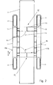
図4は、ストラドルキャリア装置1の第二実施形態の概略図を示す。このストラドルキャリア装置1は、上述したストラドルキャリア装置1に実質的に匹敵する。したがって上記の説明を参照する。これらの二つのストラドルキャリア装置1は、部品12a、12bの枢動領域14の位置、ならびにしたがってスピンドル13の配置および向きが異なる。実線で示されたセンサアセンブリ12の左側の部品12aは、垂直非作動位置で示される一方、破線はセンサアセンブリ12の部品12aの作動位置を示す。逆に、センサアセンブリ12の第二部品12bは、右側に作動位置で実線で示される一方、破線は部品12bの非作動位置を示す。この目的のために、部品12a、12bは各々両端の片方が、水平方向にまたは地面4に対して水平方向にかつストラドルキャリア装置1の走行方向Fに向けられたスピンドル13を中心に関着される。部品12a、12bは各々、作動駆動装置(図示せず)によって、いずれの場合もスピンドル13を中心に、ストラドルキャリア装置1の走行方向Fに対して直角に向けられた水平作動位置から、走行方向Fに対して直角に向けられた垂直非作動位置へ枢動することができる。この図は、走行動作中にはセンサアセンブリ12の両部品12aおよび12bが水平作動位置にあり続けるが、荷役動作中にはセンサアセンブリ12の両部品12aおよび12bが非作動位置にあるという機能を理解する目的に役立つ。
FIG. 4 shows a schematic diagram of a second embodiment of the straddle carrier device 1. The straddle carrier device 1 is substantially comparable to the straddle carrier device 1 described above. Therefore, reference is made to the above description. These two straddle carrier devices 1 differ in the position of the
例示的実施形態は単に、センサアセンブリ12を移動させるための一つの可能な変形例を示すだけである。センサアセンブリ12が作動位置と非作動位置との間で移動できるようにするために、他の枢結、折畳み固定、または回転固定が可能である。センサアセンブリ12の複合移動手順を可能にするために、空間的に移動可能な機構を設けることもできる。当然、構造隙間15の外に非作動位置用の空間が利用可能であることを前提として、非分割センサアセンブリ12も使用することができる。
The exemplary embodiment merely illustrates one possible variation for moving the
まだ荷取りされていないか、あるいはすでに荷下ろしされたコンテナ8上をストラドルキャリア装置1が走行しており、かつセンサアセンブリ12が非作動位置にあるときでも、ストラドルキャリア装置1が自動的に制御可能かつ操舵可能であるために、ストラドルキャリア装置1は、例えばレーザスキャナの形の追加センサを備えることができる。コンテナ8上の走行がある程度完了して、センサアセンブリ12を作動位置に、かつしたがって構造隙間15内に移動できるようになるまで、これらの追加センサによって、コンテナ8に対するストラドルキャリア装置1の位置を決定し、ストラドルキャリア装置1のナビゲーションのために使用することができる。
The straddle carrier device 1 is automatically controlled even when the straddle carrier device 1 is running on a
1 ストラドルキャリア装置
2 駆動歯車支持体
3 車輪
4 地面
5 支柱
6 機械プラットホーム
7 ガントリ
8 コンテナ
9 昇降装置
10 スプレッダ
11 隅金具
12 センサアセンブリ
12a センサアセンブリの部品
12b センサアセンブリの部品
13 スピンドル
14 枢動経路
15 構造隙間
16 マーキング要素
17 空間
F 走行方向
DESCRIPTION OF SYMBOLS 1
Claims (10)
Applications Claiming Priority (3)
| Application Number | Priority Date | Filing Date | Title |
|---|---|---|---|
| DE201410100833 DE102014100833B3 (en) | 2014-01-24 | 2014-01-24 | Automatically guided container gantry lift with movable sensor arrangement |
| DE102014100833.2 | 2014-01-24 | ||
| PCT/EP2015/051269 WO2015110539A1 (en) | 2014-01-24 | 2015-01-22 | Automatically guided container gantry lifting device having a movable sensor assembly |
Publications (1)
| Publication Number | Publication Date |
|---|---|
| JP2017503732A true JP2017503732A (en) | 2017-02-02 |
Family
ID=52464333
Family Applications (1)
| Application Number | Title | Priority Date | Filing Date |
|---|---|---|---|
| JP2016547149A Ceased JP2017503732A (en) | 2014-01-24 | 2015-01-22 | Self-guided container straddle carrier device with movable sensor assembly |
Country Status (8)
| Country | Link |
|---|---|
| US (1) | US20160332848A1 (en) |
| EP (1) | EP3097045A1 (en) |
| JP (1) | JP2017503732A (en) |
| CN (1) | CN105980287A (en) |
| AU (1) | AU2015208174A1 (en) |
| DE (1) | DE102014100833B3 (en) |
| SG (1) | SG11201605736VA (en) |
| WO (1) | WO2015110539A1 (en) |
Families Citing this family (11)
| Publication number | Priority date | Publication date | Assignee | Title |
|---|---|---|---|---|
| DE102015202734A1 (en) | 2015-02-16 | 2016-08-18 | Terex Cranes Germany Gmbh | Crane and method for influencing a deformation of a boom system of such a crane |
| KR101573184B1 (en) * | 2015-07-23 | 2015-11-30 | 한국가스공사 | loading and unloading device for LNG tank container |
| CN106082016A (en) * | 2016-05-24 | 2016-11-09 | 山西东械自动化科技有限公司 | Fork plate formula floor truck |
| DE102016119793A1 (en) | 2016-10-18 | 2018-04-19 | Terex Mhps Gmbh | Portal lifting device for handling containers with a sensor device |
| DE102016119839A1 (en) | 2016-10-18 | 2018-04-19 | Terex Mhps Gmbh | Method for automatically positioning a straddle carrier for containers and straddle carriers therefor |
| DE102017112661A1 (en) * | 2017-06-08 | 2018-12-13 | Konecranes Global Corporation | Automatically guided portal lifting device for containers and method for operating such a portal lifting device |
| CN107777549A (en) * | 2017-12-08 | 2018-03-09 | 王马达 | Coil embraces shifting device and container loading coil system and the application method of the system equipped with this armful of shifting device |
| CN110450798A (en) * | 2019-08-30 | 2019-11-15 | 深圳空铁科技股份有限公司 | The combined airway railway traffic system of container |
| CN111994799A (en) * | 2020-08-05 | 2020-11-27 | 龙合智能装备制造有限公司 | Carrier of unmanned intelligent portal frame structure and using method thereof |
| CN112551444A (en) * | 2020-12-03 | 2021-03-26 | 湖北三江航天万山特种车辆有限公司 | Mixing pot lifting device |
| CN112978579B (en) * | 2021-05-13 | 2021-07-23 | 新乡职业技术学院 | Crane with anti-collision control system |
Citations (3)
| Publication number | Priority date | Publication date | Assignee | Title |
|---|---|---|---|---|
| JP2001322720A (en) * | 2000-05-16 | 2001-11-20 | Tcm Corp | Container loading and unloading method and its sytem |
| JP2007145490A (en) * | 2005-11-28 | 2007-06-14 | Mitsubishi Heavy Ind Ltd | Moving body control device, moving body using this control device and moving body control method |
| JP2014511807A (en) * | 2011-04-06 | 2014-05-19 | ゴットヴァルト ポート テクノロジー ゲーエムベーハー | Straddle carrier device with electric drive |
Family Cites Families (4)
| Publication number | Priority date | Publication date | Assignee | Title |
|---|---|---|---|---|
| DE10323641A1 (en) * | 2003-05-26 | 2005-01-05 | Daimlerchrysler Ag | Movable sensor device on the load means of a forklift |
| DE102006044645A1 (en) | 2006-09-21 | 2008-04-10 | Gottwald Port Technology Gmbh | Method and system for determining the position and orientation of an unmanned vehicle and corresponding vehicle |
| DE102008011539B3 (en) | 2008-02-28 | 2009-06-18 | Noell Mobile Systems Gmbh | Fully automatic straddle carrier with local radiolocation and laser steering |
| RU2569051C2 (en) * | 2011-04-21 | 2015-11-20 | Коункрэйнс Плк | Method and device of vehicle position location |
-
2014
- 2014-01-24 DE DE201410100833 patent/DE102014100833B3/en not_active Expired - Fee Related
-
2015
- 2015-01-22 US US15/112,621 patent/US20160332848A1/en not_active Abandoned
- 2015-01-22 WO PCT/EP2015/051269 patent/WO2015110539A1/en active Application Filing
- 2015-01-22 AU AU2015208174A patent/AU2015208174A1/en not_active Abandoned
- 2015-01-22 SG SG11201605736VA patent/SG11201605736VA/en unknown
- 2015-01-22 CN CN201580005585.9A patent/CN105980287A/en active Pending
- 2015-01-22 EP EP15703479.4A patent/EP3097045A1/en not_active Withdrawn
- 2015-01-22 JP JP2016547149A patent/JP2017503732A/en not_active Ceased
Patent Citations (3)
| Publication number | Priority date | Publication date | Assignee | Title |
|---|---|---|---|---|
| JP2001322720A (en) * | 2000-05-16 | 2001-11-20 | Tcm Corp | Container loading and unloading method and its sytem |
| JP2007145490A (en) * | 2005-11-28 | 2007-06-14 | Mitsubishi Heavy Ind Ltd | Moving body control device, moving body using this control device and moving body control method |
| JP2014511807A (en) * | 2011-04-06 | 2014-05-19 | ゴットヴァルト ポート テクノロジー ゲーエムベーハー | Straddle carrier device with electric drive |
Also Published As
| Publication number | Publication date |
|---|---|
| US20160332848A1 (en) | 2016-11-17 |
| EP3097045A1 (en) | 2016-11-30 |
| CN105980287A (en) | 2016-09-28 |
| AU2015208174A1 (en) | 2016-07-21 |
| DE102014100833B3 (en) | 2015-03-19 |
| WO2015110539A1 (en) | 2015-07-30 |
| SG11201605736VA (en) | 2016-08-30 |
Similar Documents
| Publication | Publication Date | Title |
|---|---|---|
| JP2017503732A (en) | Self-guided container straddle carrier device with movable sensor assembly | |
| JP5886863B2 (en) | Container transshipment system | |
| US11242229B2 (en) | Arrangement of a gantry lifting device and of a row of spaced-apart marking elements | |
| CN106647762B (en) | System and method for sensing loads being transported by a materials handling vehicle | |
| JP5834078B2 (en) | Cargo handling system | |
| JP5755404B2 (en) | Container terminal | |
| KR20070033972A (en) | Automated loading system and method | |
| CN110691752B (en) | Automatically guided door lifting device for containers and method for operating such a door lifting device | |
| JP2018111589A (en) | Horizontal conveyance carriage | |
| CN108529493B (en) | Land transportation vehicle with improved sensor solution and land transportation system | |
| CN109963806B (en) | Method for automatically positioning straddle carrier for container and straddle carrier thereof | |
| JP2011240781A (en) | Automated guided vehicle and truck conveyance method | |
| JP6492324B2 (en) | Container terminal | |
| KR20170033259A (en) | Stacker crane with an intermediate storage area for containers | |
| CN110944926A (en) | System for radio positioning of transport vehicles for containers | |
| TWI709522B (en) | Sensor trolley and corresponding container crane | |
| WO2023104088A1 (en) | Loading and unloading method, underride agv, composite four-legged tray, and forklift agv | |
| CN108910770A (en) | A kind of fork truck | |
| JP2015531730A (en) | System for contactless inspection of containers in handling plants, especially ISO containers | |
| CN208916744U (en) | A kind of fork truck | |
| JP6113551B2 (en) | Container terminal and container terminal operation method | |
| JP2019139666A (en) | Unmanned carrier and control method therefor | |
| JP7373952B2 (en) | Transport systems and automated guided vehicles | |
| JP7207667B2 (en) | Pallet rest structure | |
| US20230202817A1 (en) | Control method for mobile object, mobile object, and computer-readable storage medium |
Legal Events
| Date | Code | Title | Description |
|---|---|---|---|
| A621 | Written request for application examination |
Free format text: JAPANESE INTERMEDIATE CODE: A621 Effective date: 20160826 |
|
| A977 | Report on retrieval |
Free format text: JAPANESE INTERMEDIATE CODE: A971007 Effective date: 20170605 |
|
| A01 | Written decision to grant a patent or to grant a registration (utility model) |
Free format text: JAPANESE INTERMEDIATE CODE: A01 Effective date: 20170801 |
|
| A045 | Written measure of dismissal of application [lapsed due to lack of payment] |
Free format text: JAPANESE INTERMEDIATE CODE: A045 Effective date: 20171226 |