JP2017202242A5 - - Google Patents
Download PDFInfo
- Publication number
- JP2017202242A5 JP2017202242A5 JP2016097270A JP2016097270A JP2017202242A5 JP 2017202242 A5 JP2017202242 A5 JP 2017202242A5 JP 2016097270 A JP2016097270 A JP 2016097270A JP 2016097270 A JP2016097270 A JP 2016097270A JP 2017202242 A5 JP2017202242 A5 JP 2017202242A5
- Authority
- JP
- Japan
- Prior art keywords
- mold
- original plate
- thermoplastic resin
- resin sheet
- pattern
- Prior art date
- Legal status (The legal status is an assumption and is not a legal conclusion. Google has not performed a legal analysis and makes no representation as to the accuracy of the status listed.)
- Granted
Links
- 238000004519 manufacturing process Methods 0.000 claims description 47
- 229920005992 thermoplastic resin Polymers 0.000 claims description 45
- 238000000034 method Methods 0.000 claims description 38
- 229920000642 polymer Polymers 0.000 claims description 21
- 238000005323 electroforming Methods 0.000 claims description 18
- 238000003825 pressing Methods 0.000 claims description 9
- 239000002184 metal Substances 0.000 claims description 4
- 229920005989 resin Polymers 0.000 claims description 3
- 239000011347 resin Substances 0.000 claims description 3
- 238000001035 drying Methods 0.000 claims 4
- 230000002093 peripheral Effects 0.000 claims 2
- 238000002360 preparation method Methods 0.000 claims 1
- 230000002441 reversible Effects 0.000 claims 1
- 238000010586 diagram Methods 0.000 description 5
- 238000005520 cutting process Methods 0.000 description 4
- 230000000875 corresponding Effects 0.000 description 3
- 238000006073 displacement reaction Methods 0.000 description 1
- OZAIFHULBGXAKX-UHFFFAOYSA-N precursor Substances N#CC(C)(C)N=NC(C)(C)C#N OZAIFHULBGXAKX-UHFFFAOYSA-N 0.000 description 1
- 230000000630 rising Effects 0.000 description 1
- 230000002522 swelling Effects 0.000 description 1
Images
Description
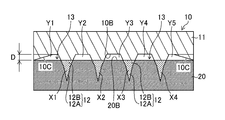
そして、傾斜部10Cの最大厚みDは、突起状パターン10Aを構成する16個の突起部12(12A)について、熱可塑性樹脂シート20に押し込んだ部分(図4Aの網状部分)の合計体積(X1+X2+X3+X4+……+X16)と、原版10の平面10B、熱可塑性樹脂シート20の表面20B、及び傾斜部10Cで囲まれた空間13(図4Aの白抜き部分)の合計体積(Y1+Y2+Y3+Y4+Y5+……+Y25)とが等しくなるように設定する。なお、突起状パターン10Aが4行×4列の2次元配列で合計16個の突起部12(12A)が配列されている場合、空間13は25個形成される。
The maximum thickness D of the
この場合も、傾斜部10Cの最大厚みDは、熱可塑性樹脂シート20に押し込んだ部分(図4Bの網状部分)の合計体積(X1+X2+X3+X4+……+X16)と、原版10の平面10B、熱可塑性樹脂シート20の表面20B、及び傾斜部10Cで囲まれた空間13(図4Bの白抜き部分)の合計体積(Y1+Y2+Y3+Y4+Y5+……+Y25)とが等しくなるように設定する。
Again, the maximum thickness D of the
図8A及び図8Bは、図2A及び図2Bで示した原版10の直線型の傾斜部10Cと弓型の傾斜部10Cとにおいて、熱可塑性樹脂シート20の表面20Bの凹状パターン20Aの端部に形成される盛り上がり部Pがどのように相違するかを対比した図である。なお、図8A及び図8Bでは、原版10の傾斜部10Cの部分及び傾斜部10Cに対応する熱可塑性樹脂シート20の部分のみを図示している。
FIGS. 8A and 8B show the
図8Aは直線型の傾斜部10Cの場合で、図8Aの左側の図は原版10の傾斜部10Cと熱可塑性樹脂シート20の表面20Bとが押圧により密接したときの図であり、右側の図は密接しなかったときの図である。また、図8Bは弓型の傾斜部10Cの場合で、図8Bの左側の図は原版10の傾斜部10Cと熱可塑性樹脂シート20の表面20Bとが押圧により密接したときの図であり、右側の図は密接しなかったときの図である。
FIG. 8A shows the case of the linear
図9A及び図9Bは、直線型の傾斜部10Cの傾斜終端に平坦部10Dが無い場合(図9A)と、有る場合(図9B)とにおいて、熱可塑性樹脂シート20の表面20Bの凹状パターン20Aの端部に形成される盛り上がり部Pがどのように相違するかを対比した図である。なお、図9A及び図9Bでは、原版10の傾斜部10Cの部分及び傾斜部10Cに対応する熱可塑性樹脂シート20の部分のみを図示している。
9A and 9B show a concave pattern 20A on the
図10は、位置決め機能を備えた押圧装置30の一例を示す概略構成図である。図10に示すように、押圧装置30は、原版10をZ軸方向に駆動するZ軸駆動機構32と、Z軸駆動機構32に連結された連結部34と、連結部34に取り付けられた保持部36と、熱可塑性樹脂シート20を支持するテーブル38と、テーブル38をX軸方向に駆動するX軸駆動機構40と、テーブル38をY軸方向に駆動するY軸駆動機構42と、架台44と、制御システム46と、レーザー変位計48と、を有している。そして、原版10は保持部36により、例えば吸着等により保持されている。
FIG. 10 is a schematic configuration diagram illustrating an example of a pressing device 30 having a positioning function. As shown in FIG. 10, the pressing device 30 includes a Z-axis drive mechanism 32 that drives the original 10 in the Z-axis direction, a connection portion 34 that is connected to the Z-axis drive mechanism 32, and a holding unit that is attached to the connection portion 34. A portion 36, a table 38 that supports the
また、図示しなかったが、図12Aの直線型の傾斜部10Cの傾斜終端に連続して図3Aのように平坦部10Dを設けることができ、図12Bの弓型の傾斜部10Cの傾斜終端に連続して図3Bのように平坦部10Dを設けることができる。
Although not shown, a flat portion 10D can be provided as shown in FIG. 3A in succession to the inclined end of the linear
図14A及び図14Bは、図13の突起部12を有する原版10の縦断面図であり、図14Aは直線型の傾斜部10Cを有する場合、図14Bは弓型の傾斜部10Cを有する場合である。なお、図14A及び図14Bは、原版10を概念的に示した図であり、図14A及び図14Bと図13とで、突起状パターン10Aを構成する突起部12の数が異なっている。
14A and 14B are longitudinal sectional views of the
また、図示しなかったが、図14Aの直線型の傾斜部10Cの傾斜終端に連続して図3Aのように平坦部10Dを設けることができ、図14Bの弓型の傾斜部10Cの傾斜終端に連続して図3Bのように平坦部10Dを設けることができる。
Although not shown, a flat portion 10D can be provided as shown in FIG. 3A continuously from the inclined end of the linear
図15A〜図15Dは、図11の錐台部12Bと針部12Aとで構成される突起部12を有する突起状パターン10Aと、弓型の傾斜部10Cとの組み合わせを有する原版10でモールド22を作製する工程を示したものである。
Figure 15A~ FIG. 15D,
図15Bに示すように、加熱された原版10を熱可塑性樹脂シート20の表面20Bの側に押圧する。これにより、原版10の突起状パターン10Aが熱可塑性樹脂シート20に押圧される。図15Bは、原版10の突起状パターン10Aを構成する突起部12の途中までを熱可塑性樹脂シート20に押し込んだ図である。この突起状パターン10Aの押し込みによって、熱可塑性樹脂シート20は突起部12の押し込み体積に相当する体積分だけ表面20Bが盛り上がり、盛り上がり部Pが形成される。
As shown in FIG. 15B, the heated
次いで、加熱された原版10を、押圧装置30のZ軸駆動機構32により、熱可塑性樹脂シート20の表面20Bの側に押圧する。この押圧によって、原版10の突起状パターン10Aが熱可塑性樹脂シート20に押圧されて熱可塑性樹脂シート20の表面20Bが盛り上がる。
Next, the heated
次に、図16Dに示すように、原版10と熱可塑性樹脂シート20とを引き離して、熱可塑性樹脂シート20の表面20Bの側に、突起状パターン10Aの反転形状の凹状パターン20Aを形成する。なお、原版10と熱可塑性樹脂シート20との引き離しは、上述したZ軸駆動機構32により実行することができる。
Next, as illustrated in FIG. 16D, the
Claims (13)
加熱された前記原版を、前記原版の傾斜部と前記熱可塑性樹脂シートの表面とが密接する位置で、前記熱可塑性樹脂シートに押圧し、前記原版を押圧した状態で前記原版を冷却し、前記原版と前記熱可塑性樹脂シートと引き離して、前記熱可塑性樹脂シートに前記突起状パターンの反転形状の凹状パターンを形成する形成工程と、を備えたモールドの作製方法。 Preparation for preparing an original plate having an inclined portion that is formed in an outer peripheral portion of a protruding pattern formed in a central portion on a table and gradually increases in thickness from the inside toward the outside, and a thermoplastic resin sheet Process,
The heated original plate is pressed against the thermoplastic resin sheet at a position where the inclined portion of the original plate and the surface of the thermoplastic resin sheet are in close contact with each other, and the original plate is cooled while the original plate is pressed, A forming step of forming an inverted concave pattern of the protruding pattern on the thermoplastic resin sheet by separating the original plate from the thermoplastic resin sheet.
前記モールドの凹状パターンにポリマー溶解液を供給する供給工程と、
前記ポリマー溶解液を乾燥させてポリマーシートとする乾燥工程と、
前記ポリマーシートを前記モールドから剥離するポリマーシート剥離工程と、
を含む突起状パターンを有するパターンシートの製造方法。 A step of producing a mold by the production method according to claim 1;
Supplying a polymer solution to the concave pattern of the mold;
A drying step of drying the polymer solution to form a polymer sheet;
A polymer sheet peeling step of peeling the polymer sheet from the mold;
The manufacturing method of the pattern sheet | seat which has a protruding pattern containing this.
前記モールドの凹状パターンに、電鋳法により金属体を形成する電鋳工程と、
前記金属体を前記モールドから剥離する剥離工程と、
を含む突起状パターンを有する電鋳金型の作製方法。 A step of producing a mold by the production method according to claim 1;
An electroforming step of forming a metal body by electroforming on the concave pattern of the mold;
A peeling step of peeling the metal body from the mold;
A method for producing an electroforming mold having a protruding pattern including:
突起状パターンを有する前記電鋳金型を用いて、前記電鋳金型の突起状パターンの反転形状である凹状パターンを有する樹脂製のモールドを作製する工程と、
を含む電鋳金型を用いたモールドの作製方法。 Producing an electroformed mold by the production method according to claim 9;
Using the electroformed mold having a protruding pattern, producing a resin mold having a concave pattern that is a reversal of the protruding pattern of the electroformed mold; and
A method for producing a mold using an electroforming mold containing
前記モールドの凹状パターンにポリマー溶解液を供給する供給工程と、
前記ポリマー溶解液を乾燥させてポリマーシートとする乾燥工程と、
前記ポリマーシートを前記モールドから剥離する剥離工程と、
を含む突起状パターンを有するパターンシートの製造方法。 Producing a mold by the production method according to claim 10;
Supplying a polymer solution to the concave pattern of the mold;
A drying step of drying the polymer solution to form a polymer sheet;
A peeling step of peeling the polymer sheet from the mold;
The manufacturing method of the pattern sheet | seat which has a protruding pattern containing this.
平面の上の中央部に形成された前記突起状パターンの外周部に囲い状に形成されて内側から外側に向けて厚みが徐々に増加する傾斜部を有する原版。 A master plate that presses against the surface of a thermoplastic resin sheet to transfer the protruding pattern to the thermoplastic resin sheet,
An original plate having an inclined portion which is formed in an outer peripheral portion of the protruding pattern formed in a central portion on a flat surface and gradually increases in thickness from the inside toward the outside.
Priority Applications (3)
| Application Number | Priority Date | Filing Date | Title |
|---|---|---|---|
| JP2016097270A JP6571586B2 (en) | 2016-05-13 | 2016-05-13 | Method for producing mold, method for producing pattern sheet, method for producing electroformed mold, and method for producing mold using electroformed mold |
| EP17170440.6A EP3243624B1 (en) | 2016-05-13 | 2017-05-10 | Production method of mold, manufacturing method of pattern sheet, production method of electroform, production method of mold using electroform, and original |
| US15/592,199 US10648095B2 (en) | 2016-05-13 | 2017-05-11 | Production method of mold, manufacturing method of pattern sheet, production method of electroform, production method of mold using electroform, and original |
Applications Claiming Priority (1)
| Application Number | Priority Date | Filing Date | Title |
|---|---|---|---|
| JP2016097270A JP6571586B2 (en) | 2016-05-13 | 2016-05-13 | Method for producing mold, method for producing pattern sheet, method for producing electroformed mold, and method for producing mold using electroformed mold |
Publications (3)
| Publication Number | Publication Date |
|---|---|
| JP2017202242A JP2017202242A (en) | 2017-11-16 |
| JP2017202242A5 true JP2017202242A5 (en) | 2018-10-04 |
| JP6571586B2 JP6571586B2 (en) | 2019-09-04 |
Family
ID=58707317
Family Applications (1)
| Application Number | Title | Priority Date | Filing Date |
|---|---|---|---|
| JP2016097270A Active JP6571586B2 (en) | 2016-05-13 | 2016-05-13 | Method for producing mold, method for producing pattern sheet, method for producing electroformed mold, and method for producing mold using electroformed mold |
Country Status (3)
| Country | Link |
|---|---|
| US (1) | US10648095B2 (en) |
| EP (1) | EP3243624B1 (en) |
| JP (1) | JP6571586B2 (en) |
Families Citing this family (4)
| Publication number | Priority date | Publication date | Assignee | Title |
|---|---|---|---|---|
| KR102139335B1 (en) * | 2017-11-24 | 2020-07-29 | 주식회사 엘지생활건강 | Method and Apparatus for Manufacturing Microneedle Containing Coatings on Needle Tip |
| EP3778169B1 (en) * | 2018-03-27 | 2021-12-29 | FUJIFILM Corporation | Method for manufacturing mold having concave pedestal pattern and method for manufacturing pattern sheet |
| JP2019170795A (en) * | 2018-03-29 | 2019-10-10 | 凸版印刷株式会社 | Production method of microneedle and microneedle |
| JP7038679B2 (en) | 2019-03-05 | 2022-03-18 | 富士フイルム株式会社 | How to make a thermoplastic resin original plate, how to make a mold, how to make a mold, and how to make a pattern sheet |
Family Cites Families (14)
| Publication number | Priority date | Publication date | Assignee | Title |
|---|---|---|---|---|
| JPH06215423A (en) * | 1992-11-26 | 1994-08-05 | Canon Inc | Method and apparatus for producing substrate sheet for optical recording medium, production of stamper and production of photomask |
| JP2005067055A (en) * | 2003-08-26 | 2005-03-17 | Tdk Corp | Mold, substrate for optical disk, and optical disk |
| WO2005087305A1 (en) * | 2004-03-12 | 2005-09-22 | Agency For Science, Technology And Research | Methods and moulds for use in fabricating side-ported microneedles |
| JP5161707B2 (en) * | 2008-08-28 | 2013-03-13 | 株式会社日立産機システム | MICROSTRUCTURE TRANSFER MOLD AND MICROSTRUCTURE TRANSFER APPARATUS |
| JP2010213845A (en) * | 2009-03-16 | 2010-09-30 | Toppan Printing Co Ltd | Method for manufacturing needle-shaped body and needle-shaped body transfer plate |
| WO2010143466A1 (en) * | 2009-06-12 | 2010-12-16 | コニカミノルタオプト株式会社 | Production method of wafer lens, intermediate die, optical component, molding die, and production method of molding die |
| JP5433370B2 (en) * | 2009-10-16 | 2014-03-05 | 東芝機械株式会社 | Mold manufacturing method |
| JP2012055343A (en) * | 2010-09-03 | 2012-03-22 | Toray Eng Co Ltd | Microneedle sheet and method for manufacturing the same |
| JP5770055B2 (en) * | 2010-09-29 | 2015-08-26 | 富士フイルム株式会社 | Method for manufacturing needle-like array transdermal absorption sheet |
| US9789656B2 (en) * | 2011-03-07 | 2017-10-17 | Konica Minolta, Inc. | Methods for producing molding die, wafer lens, and optical lens |
| WO2012172755A1 (en) * | 2011-06-16 | 2012-12-20 | パナソニック株式会社 | Sheet, mold, and manufacturing method thereof |
| CN104780967B (en) | 2012-11-13 | 2017-04-12 | 富士胶片株式会社 | Method for manufacturing transdermal-absorption sheet |
| WO2014196522A1 (en) * | 2013-06-03 | 2014-12-11 | 凸版印刷株式会社 | Needle body manufacturing method and manufacturing device |
| CN107073210B (en) * | 2014-09-03 | 2020-11-10 | 新南创新私人有限公司 | Microfluidic device and fabrication |
-
2016
- 2016-05-13 JP JP2016097270A patent/JP6571586B2/en active Active
-
2017
- 2017-05-10 EP EP17170440.6A patent/EP3243624B1/en active Active
- 2017-05-11 US US15/592,199 patent/US10648095B2/en active Active
Similar Documents
| Publication | Publication Date | Title |
|---|---|---|
| JP2017202242A5 (en) | ||
| JP5010445B2 (en) | Manufacturing method of mold for microlens array | |
| KR101034592B1 (en) | Flexible sheet forming apparatus with multiple forming punches and forming method using the same | |
| JP2007077003A (en) | Flat optical element semi-finished product from which a plurality of optical elements are made and apparatus for manufacturing the same | |
| JP2015504547A (en) | Multi-touch touch screen panel and manufacturing method thereof | |
| JP6587345B2 (en) | Method for producing resin mold | |
| AU2017298018A1 (en) | Blow mould | |
| JP5822071B2 (en) | Method and apparatus for forming plate-like porous product | |
| JP5606965B2 (en) | Manufacturing method of cylindrical object | |
| JP2010143227A (en) | Screen printing plate | |
| JP2018097065A (en) | Stereoscopic image formation apparatus and manufacturing method of the same | |
| JP2008023920A5 (en) | ||
| JP2005049721A (en) | Method of manufacturing optical element | |
| JPWO2017069136A1 (en) | Electrical contact | |
| EP1598168B1 (en) | Method and device for the manufacture of a three-dimensional structure | |
| WO2022093570A1 (en) | Material interlocking | |
| JP2012230289A5 (en) | ||
| JP2007015016A (en) | Method for manufacturing metal plate having cambered hole | |
| JP5152663B2 (en) | Multilayer conductive bumped substrate sheet laminate manufacturing method and conductive bumped substrate sheet manufacturing method | |
| JP2021172005A (en) | Shaping piece and mold | |
| KR101609196B1 (en) | Light Guide Plate And Manufacturing Mathod Thereof | |
| CN218430180U (en) | Easy-to-demold powder tablet press | |
| JP2010147295A (en) | Method for forming three-dimensional microstructure, and method for manufacturing liquid ejecting head | |
| JP2014117764A (en) | Pore machining method and pore machining device | |
| JP2005230885A (en) | Sheet metal processing method |