EP3243624B1 - Production method of mold, manufacturing method of pattern sheet, production method of electroform, production method of mold using electroform, and original - Google Patents
Production method of mold, manufacturing method of pattern sheet, production method of electroform, production method of mold using electroform, and original Download PDFInfo
- Publication number
- EP3243624B1 EP3243624B1 EP17170440.6A EP17170440A EP3243624B1 EP 3243624 B1 EP3243624 B1 EP 3243624B1 EP 17170440 A EP17170440 A EP 17170440A EP 3243624 B1 EP3243624 B1 EP 3243624B1
- Authority
- EP
- European Patent Office
- Prior art keywords
- mold
- original
- thermoplastic resin
- resin sheet
- pattern
- Prior art date
- Legal status (The legal status is an assumption and is not a legal conclusion. Google has not performed a legal analysis and makes no representation as to the accuracy of the status listed.)
- Active
Links
Images


Classifications
-
- C—CHEMISTRY; METALLURGY
- C25—ELECTROLYTIC OR ELECTROPHORETIC PROCESSES; APPARATUS THEREFOR
- C25D—PROCESSES FOR THE ELECTROLYTIC OR ELECTROPHORETIC PRODUCTION OF COATINGS; ELECTROFORMING; APPARATUS THEREFOR
- C25D1/00—Electroforming
- C25D1/10—Moulds; Masks; Masterforms
-
- B—PERFORMING OPERATIONS; TRANSPORTING
- B29—WORKING OF PLASTICS; WORKING OF SUBSTANCES IN A PLASTIC STATE IN GENERAL
- B29C—SHAPING OR JOINING OF PLASTICS; SHAPING OF MATERIAL IN A PLASTIC STATE, NOT OTHERWISE PROVIDED FOR; AFTER-TREATMENT OF THE SHAPED PRODUCTS, e.g. REPAIRING
- B29C33/00—Moulds or cores; Details thereof or accessories therefor
- B29C33/38—Moulds or cores; Details thereof or accessories therefor characterised by the material or the manufacturing process
- B29C33/3842—Manufacturing moulds, e.g. shaping the mould surface by machining
- B29C33/3857—Manufacturing moulds, e.g. shaping the mould surface by machining by making impressions of one or more parts of models, e.g. shaped articles and including possible subsequent assembly of the parts
- B29C33/3892—Preparation of the model, e.g. by assembling parts
-
- B—PERFORMING OPERATIONS; TRANSPORTING
- B29—WORKING OF PLASTICS; WORKING OF SUBSTANCES IN A PLASTIC STATE IN GENERAL
- B29C—SHAPING OR JOINING OF PLASTICS; SHAPING OF MATERIAL IN A PLASTIC STATE, NOT OTHERWISE PROVIDED FOR; AFTER-TREATMENT OF THE SHAPED PRODUCTS, e.g. REPAIRING
- B29C33/00—Moulds or cores; Details thereof or accessories therefor
- B29C33/38—Moulds or cores; Details thereof or accessories therefor characterised by the material or the manufacturing process
- B29C33/40—Plastics, e.g. foam or rubber
-
- B—PERFORMING OPERATIONS; TRANSPORTING
- B29—WORKING OF PLASTICS; WORKING OF SUBSTANCES IN A PLASTIC STATE IN GENERAL
- B29C—SHAPING OR JOINING OF PLASTICS; SHAPING OF MATERIAL IN A PLASTIC STATE, NOT OTHERWISE PROVIDED FOR; AFTER-TREATMENT OF THE SHAPED PRODUCTS, e.g. REPAIRING
- B29C33/00—Moulds or cores; Details thereof or accessories therefor
- B29C33/42—Moulds or cores; Details thereof or accessories therefor characterised by the shape of the moulding surface, e.g. ribs or grooves
- B29C33/424—Moulding surfaces provided with means for marking or patterning
-
- B—PERFORMING OPERATIONS; TRANSPORTING
- B29—WORKING OF PLASTICS; WORKING OF SUBSTANCES IN A PLASTIC STATE IN GENERAL
- B29C—SHAPING OR JOINING OF PLASTICS; SHAPING OF MATERIAL IN A PLASTIC STATE, NOT OTHERWISE PROVIDED FOR; AFTER-TREATMENT OF THE SHAPED PRODUCTS, e.g. REPAIRING
- B29C39/00—Shaping by casting, i.e. introducing the moulding material into a mould or between confining surfaces without significant moulding pressure; Apparatus therefor
- B29C39/02—Shaping by casting, i.e. introducing the moulding material into a mould or between confining surfaces without significant moulding pressure; Apparatus therefor for making articles of definite length, i.e. discrete articles
- B29C39/026—Shaping by casting, i.e. introducing the moulding material into a mould or between confining surfaces without significant moulding pressure; Apparatus therefor for making articles of definite length, i.e. discrete articles characterised by the shape of the surface
-
- B—PERFORMING OPERATIONS; TRANSPORTING
- B29—WORKING OF PLASTICS; WORKING OF SUBSTANCES IN A PLASTIC STATE IN GENERAL
- B29C—SHAPING OR JOINING OF PLASTICS; SHAPING OF MATERIAL IN A PLASTIC STATE, NOT OTHERWISE PROVIDED FOR; AFTER-TREATMENT OF THE SHAPED PRODUCTS, e.g. REPAIRING
- B29C39/00—Shaping by casting, i.e. introducing the moulding material into a mould or between confining surfaces without significant moulding pressure; Apparatus therefor
- B29C39/22—Component parts, details or accessories; Auxiliary operations
- B29C39/26—Moulds or cores
-
- B—PERFORMING OPERATIONS; TRANSPORTING
- B29—WORKING OF PLASTICS; WORKING OF SUBSTANCES IN A PLASTIC STATE IN GENERAL
- B29C—SHAPING OR JOINING OF PLASTICS; SHAPING OF MATERIAL IN A PLASTIC STATE, NOT OTHERWISE PROVIDED FOR; AFTER-TREATMENT OF THE SHAPED PRODUCTS, e.g. REPAIRING
- B29C39/00—Shaping by casting, i.e. introducing the moulding material into a mould or between confining surfaces without significant moulding pressure; Apparatus therefor
- B29C39/22—Component parts, details or accessories; Auxiliary operations
- B29C39/36—Removing moulded articles
-
- C—CHEMISTRY; METALLURGY
- C25—ELECTROLYTIC OR ELECTROPHORETIC PROCESSES; APPARATUS THEREFOR
- C25D—PROCESSES FOR THE ELECTROLYTIC OR ELECTROPHORETIC PRODUCTION OF COATINGS; ELECTROFORMING; APPARATUS THEREFOR
- C25D1/00—Electroforming
- C25D1/20—Separation of the formed objects from the electrodes with no destruction of said electrodes
-
- A—HUMAN NECESSITIES
- A61—MEDICAL OR VETERINARY SCIENCE; HYGIENE
- A61M—DEVICES FOR INTRODUCING MEDIA INTO, OR ONTO, THE BODY; DEVICES FOR TRANSDUCING BODY MEDIA OR FOR TAKING MEDIA FROM THE BODY; DEVICES FOR PRODUCING OR ENDING SLEEP OR STUPOR
- A61M37/00—Other apparatus for introducing media into the body; Percutany, i.e. introducing medicines into the body by diffusion through the skin
- A61M37/0015—Other apparatus for introducing media into the body; Percutany, i.e. introducing medicines into the body by diffusion through the skin by using microneedles
- A61M2037/0053—Methods for producing microneedles
-
- B—PERFORMING OPERATIONS; TRANSPORTING
- B29—WORKING OF PLASTICS; WORKING OF SUBSTANCES IN A PLASTIC STATE IN GENERAL
- B29K—INDEXING SCHEME ASSOCIATED WITH SUBCLASSES B29B, B29C OR B29D, RELATING TO MOULDING MATERIALS OR TO MATERIALS FOR MOULDS, REINFORCEMENTS, FILLERS OR PREFORMED PARTS, e.g. INSERTS
- B29K2105/00—Condition, form or state of moulded material or of the material to be shaped
- B29K2105/0005—Condition, form or state of moulded material or of the material to be shaped containing compounding ingredients
- B29K2105/0035—Medical or pharmaceutical agents
-
- B—PERFORMING OPERATIONS; TRANSPORTING
- B29—WORKING OF PLASTICS; WORKING OF SUBSTANCES IN A PLASTIC STATE IN GENERAL
- B29L—INDEXING SCHEME ASSOCIATED WITH SUBCLASS B29C, RELATING TO PARTICULAR ARTICLES
- B29L2007/00—Flat articles, e.g. films or sheets
-
- B—PERFORMING OPERATIONS; TRANSPORTING
- B29—WORKING OF PLASTICS; WORKING OF SUBSTANCES IN A PLASTIC STATE IN GENERAL
- B29L—INDEXING SCHEME ASSOCIATED WITH SUBCLASS B29C, RELATING TO PARTICULAR ARTICLES
- B29L2031/00—Other particular articles
- B29L2031/753—Medical equipment; Accessories therefor
- B29L2031/7544—Injection needles, syringes
-
- B—PERFORMING OPERATIONS; TRANSPORTING
- B29—WORKING OF PLASTICS; WORKING OF SUBSTANCES IN A PLASTIC STATE IN GENERAL
- B29L—INDEXING SCHEME ASSOCIATED WITH SUBCLASS B29C, RELATING TO PARTICULAR ARTICLES
- B29L2031/00—Other particular articles
- B29L2031/756—Microarticles, nanoarticles
Definitions
- the present invention relates to a production method of a mold, a manufacturing method of a pattern sheet, a production method of an electroform, a production method of a mold using an electroform, and an original.
- microneedle array is an array of microneedles (also referred to as fine needles or small needles) which contain drugs and are biodegradable. By attaching this microneedle array to the skin, each microneedle pierces the skin, these microneedles are absorbed in the skin such that the drugs contained in each microneedle can be administered into the skin. Microneedle arrays are also called percutaneous absorption sheets.
- JP2007-535343A discloses a production method of a mold base for manufacturing microneedles.
- a mold base for manufacturing microneedles is produced by pressing a master model having master model needle arrays against a mold plate for manufacturing microneedles, and a formed product having a fine pattern is produced by using the mold base for manufacturing microneedles.
- JP2011-083993A discloses transferring a transfer pattern formed on a mold to a plurality of points of a thermoplastic resin.
- a heated mold is pressed against a thermoplastic resin and is cooled, and the mold is separated from the thermoplastic resin, thereby transferring the transfer pattern of the mold to the thermoplastic resin.
- moving the heated mold, pressing the mold against the thermoplastic resin and cooling the mold, and separating the mold from the thermoplastic resin are repeated, thereby transferring the transfer pattern of the mold to the thermoplastic resin.
- the master model (original) having a plurality of the master model needle arrays (for example, 8 ⁇ 8) is used. That is, a large master model is required, and thus there is concern that the number of operations for producing the master model may increase.
- the transfer pattern of the mold is transferred to the thermoplastic resin while pressing the flat surface of the mold against the thermoplastic resin. Therefore, there may be cases where the thermoplastic resin is raised at the end portion of the mold, and as a result, there is concern that a stepped portion may be formed between the molds.
- a duplicate mold also called an electroform
- a formed product such as a percutaneous absorption sheet
- the present invention has been made taking the above circumstances into consideration, and an object thereof is to provide a production method of a mold, a manufacturing method of a pattern sheet, a production method of an electroform, a production method of a mold using an electroform, and an original capable of preventing peeling failure during production of a duplicate product or formed product from a mold and improving the releasability of the original itself by preventing the generation of a stepped portion at an end portion of a recessed pattern of the surface of the mold.
- a production method of a mold comprising: a preparation process of preparing an original having an inclined portion which is formed in an enclosed shape on an outer peripheral portion of a protruding pattern formed at a center portion on a base and gradually increases in thickness from the inside toward the outside, and a thermoplastic resin sheet; and a forming process of forming a recessed pattern having an inverted shape of the protruding pattern on the thermoplastic resin sheet by pressing the original which is heated against the thermoplastic resin sheet at a position where the inclined portion of the original and a surface of the thermoplastic resin sheet are in close contact with each other, cooling the original in the state in which the original is pressed, and separating the original from the thermoplastic resin sheet.
- an alignment process of determining a position at which the original is to be pressed against the thermoplastic resin sheet by moving the original and the thermoplastic resin sheet relative to each other, and the forming process are repeatedly performed. Accordingly, the generation of a stepped portion between the recessed patterns can be prevented, and a large mold having a plurality of the recessed patterns with a single original can be produced.
- the inclined portion has a vertical sectional shape formed in a right-angled triangle such that the thickness thereof linearly increases from the inside toward the outside. Accordingly, the generation of a stepped portion can be prevented.
- the inclined portion has a vertical sectional shape formed in an arcuate shape such that the thickness thereof increases in an arc shape from the inside toward the outside and thereafter the increase in thickness gradually decreases. Accordingly, the generation of a stepped portion can be further prevented.
- the original has a flat portion which is formed to be connected to an inclination terminal of the inclined portion.
- thermoplastic resin sheet when the original is pressed against the thermoplastic resin sheet, a position of the surface of the thermoplastic resin sheet is detected, and the original is pushed from the position of the surface of the thermoplastic resin sheet by a certain amount.
- thermoplastic resin sheet when the original is pressed against the thermoplastic resin sheet, a pressure applied to the original is measured and is compared to a certain pressure value which is set, and the amount of the original being pushed is determined.
- a manufacturing method of a pattern sheet having a protruding pattern comprising: a process of producing a mold using the above-described production method; a supplying process of supplying a polymer solution to a recessed pattern of the mold; a drying process of drying the polymer solution to form a polymer sheet; and a polymer sheet peeling process of peeling the polymer sheet from the mold.
- a production method of an electroform having a protruding pattern comprising: a process of producing a mold using the above-described production method; an electroforming process of forming a metal body on a recessed pattern of the mold by an electroforming method; and a peeling process of peeling the metal body from the mold.
- a production method of a mold comprising: a process of producing an electroform using the above-described production method; and a process of, by using the electroform having a protruding pattern, producing a mold which has a recessed pattern which is an inverted shape of the protruding pattern of the electroform and is made of a resin.
- a manufacturing method of a pattern sheet having a protruding pattern comprising: a process of producing a mold using the production method of an electroform described above; a supplying process of supplying a polymer solution to a recessed pattern of the mold; a drying process of drying the polymer solution to form a polymer sheet; and a peeling process of peeling the polymer sheet from the mold.
- an original which is pressed against a surface of a thermoplastic resin sheet to transfer a protruding pattern onto the thermoplastic resin sheet, the original comprising: an inclined portion which is formed in an enclosed shape on an outer peripheral portion of the protruding pattern formed at a center portion on a base and gradually increases in thickness from the inside toward the outside.
- a preferred aspect of the original further comprises a flat portion which is formed to be connected to an inclination terminal of the inclined portion.
- the production method of a mold the manufacturing method of a pattern sheet, the production method of an electroform, the production method of a mold using an electroform, and the original of the present invention, the generation of a stepped portion at the end portion of the recessed pattern of the mold can be prevented.
- Fig. 1 is a perspective view illustrating a first embodiment of an original of the present invention.
- the first embodiment of the original 10 includes a protruding pattern 10A formed at the center portion on one flat surface 10B of a base 11, and an inclined portion 10C formed on the outer peripheral portion of the protruding pattern 10A.
- the original 10 having the protruding pattern 10A and the inclined portion 10C is produced, for example, by machining a metal substrate, which is to become the original 10, using a cutting tool such as a diamond insert bite.
- a metal substrate stainless steel, an aluminum alloy, Ni, or the like may be used.
- the protruding pattern 10A of the original 10 is basically the same as the protruding pattern of a pattern sheet (a formed product such as a percutaneous absorption sheet) to be produced.
- the protruding pattern 10A refers to a state in which a protrusion 12 protruding in a direction away from the flat surface 10B of the original 10 is disposed on the flat surface 10B of the original 10.
- the number of protrusions 12 is not limited.
- the flat surface 10B may be a perfectly flat surface or may be a flat surface at first glance.
- the protrusion 12 is constituted by a needle portion 12A which is tapered in the direction away from the flat surface 10B.
- the protrusion 12 is a so-called cone, and the cone includes a pyramid, a circular cone, and the like.
- the protrusion 12 preferably has a height of 100 to 2000 ⁇ m from the flat surface 10B of the original 10 and has a tip diameter of ⁇ 50 ⁇ m or less.
- the interval between adjacent protrusions 12 is 300 to 2000 ⁇ m.
- the aspect ratio (the height of the protrusion / the width of the bottom surface of the protrusion) of the protrusion 12 is 1 to 5.
- the inclined portion 10C is formed in an enclosed shape on the outer peripheral portion of the protruding pattern 10A formed at the center portion on the flat surface 10B and gradually increases in thickness from the inside (the center side of the flat surface 10B) toward the outside (the end portion side of the flat surface 10B).
- the thickness of the inclined portion 10C can be referred to as the height of the inclined portion 10C.
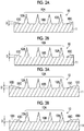
- Figs. 2A and 2B show two preferable embodiments in which the thickness of the inclined portion 10C gradually increases.
- the inclined portion 10C in Fig. 2A has a vertical sectional shape formed in a right-angled triangle such that the thickness thereof linearly increases from the inside (the center portion side) toward the outside (the periphery portion side) of the flat surface 10B (hereinafter, referred to as a linear inclined portion). Furthermore, the inclined portion 10C in Fig. 2B has a vertical sectional shape formed in an arcuate shape such that the thickness thereof increases in an arc shape from the inside toward the outside of the flag surface 10B and thereafter the increase in thickness gradually decreases, that is, the thickness increases so-called arcuately (hereinafter, referred to as an arcuate inclined portion).
- the term "a vertical sectional shape formed in an arcuate shape” means, when a horizontal oval shape is divided into four equal parts by a vertical line and a horizontal line passing through the center, the sectional shape of one divided part.
- Figs. 3A and 3B are perspective views illustrating a second embodiment of the original 10 of the present invention.
- the second embodiment of the original 10 includes the protruding pattern 10A formed at the center portion on one flat surface 10B of the base 11, the inclined portion 10C formed on the outer peripheral portion of the protruding pattern 10A, and a flat portion 10D which is formed to be connected to the inclination terminal of the inclined portion 10C.
- the inclination terminal refers to a terminal where the thickness of the inclined portion 10C gradually increases to the maximum thickness D and the inclination ends. Therefore, the flat portion 10D is formed to have the same thickness as the maximum thickness D of the inclined portion 10C.
- the original 10 in Fig. 3A refers to a case where the flat portion 10D is formed to be connected to the inclination terminal of the linear inclined portion 10C.
- the original 10 in Fig. 3B refers to a case where the flat portion 10D is formed to be connected to the inclination terminal of the arcuate inclined portion 10C.
- the protruding pattern 10A of the original 10 is the same as the protruding pattern 10A of the first embodiment.
- the maximum thickness D of the inclined portion 10C of the original 10 is set as follows.
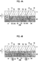
- Fig. 4A is a vertical sectional view illustrating the original 10 which is pressed against a surface 20B side of a thermoplastic resin sheet 20 such that the plurality of protrusions 12 (12A) of the protruding pattern 10A are pushed into the thermoplastic resin sheet 20 until the part of the linear inclined portion 10C having the maximum thickness D comes into close contact with the surface 20B of the thermoplastic resin sheet 20.
- the original 10 is an example in which a total of 16 protrusions 12 (12A) are arranged in a two-dimensional array of 4 rows and 4 columns in the protruding pattern 10A, and the inclined portion 10C is formed in an enclosed shape the outer peripheral portion of the protruding pattern 10A.
- Fig. 4A is a vertical sectional view of the protruding pattern 10A, and the protrusions 12 are also formed in the forward and rearward directions of Fig. 4A .
- Fig. 4A is a vertical sectional view conceptually illustrating the original 10, and Fig. 4A and Fig. 1 are different from each other in the number of protrusions 12 constituting the protruding pattern 10A.
- the maximum thickness D of the inclined portion 10C is set so that the total volume (X1 + X2 + X3 + X4 + ... + X16) of the parts (mesh parts in Fig. 4A ) of the 16 protrusions 12 (12A) constituting the protruding pattern 10A, which are pushed into the thermoplastic resin sheet 20, is equal to the total volume (Y1 + Y2 + Y3 + Y4 + Y5 + ... + Y25) of spaces 13 (white parts in Fig. 4A ) enclosed by the flat surface 10B of the original 10, the surface 20B of the thermoplastic resin sheet 20, and the inclined portion 10C.
- 25 spaces 13 are formed.
- Fig. 4B is a vertical sectional view illustrating the protruding pattern 10A, in which the shape of the protrusion 12 is constituted by the needle portion 12A and a frustum portion 12B, being pushed into the thermoplastic resin sheet 20 until the part of the linear inclined portion 10C having the maximum thickness D comes into close contact with the surface 20B of the thermoplastic resin sheet 20.
- Fig. 4B refers to a case where the needle portion 12A and a part of the frustum portion 12B are pushed into the thermoplastic resin sheet 20.
- the maximum thickness D of the inclined portion 10C is set so that the total volume (X1 + X2 + X3 + X4 + ... + X16) of the parts (mesh parts in Fig. 4B ) pushed into the thermoplastic resin sheet 20 is equal to the total volume (Y1 + Y2 + Y3 + Y4 + Y5 + ... + Y25) of the spaces 13 (white parts in Fig. 4B ) enclosed by the flat surface 10B of the original 10, the surface 20B of the thermoplastic resin sheet 20, and the inclined portion 10C.
- the maximum thickness D of the inclined portion 10C is set so that all the raised parts on the surface 20B of the thermoplastic resin sheet 20 corresponding to the total volume (X1 + X2 + X3 + X4 + ... + X16) of the pushed parts of the protruding pattern 10A can be accommodated in the total volume (Y1 + Y2 + Y3 + Y4 + Y5 + ... + Y25) of the spaces 13, regardless of the shape (linear shape, or arcuate shape) of the inclined portion 10C, the presence or absence of the flat portion 10D, and the shape of the protrusion 12.
- Figs. 5A to 5D are process diagrams illustrating a procedure of the production method of a mold.
- Fig. 5A illustrates a preparation process of preparing the original 10, and the thermoplastic resin sheet 20 which is the material of the mold.
- the thermoplastic resin sheet 20 is set, for example, on a table (not illustrated).
- the thermoplastic resin sheet 20 has a thickness of 0.5 to 2.0 mm, for example, and has the surface 20B.
- a recessed pattern, which will be described later, is formed on the surface 20B side. It is preferable that the thickness of the thermoplastic resin sheet 20 is equal to or greater than at least the height of the protrusion 12 of the original 10.
- thermoplastic resin forming the thermoplastic resin sheet 20 is not particularly limited.
- polyethylene terephthalate, polycarbonate, polymethyl methacrylate, polystyrene, polyethylene, a liquid crystal polymer, and polylactic acid may be suitably used.
- thermoplastic resin sheet 20 means a thermoplastic resin in a state of having a small film thickness and a self-supporting property at room temperature.
- Self-supporting property means that a single body can hold its form without the support of other members.
- Figs. 5B to 5D show a forming process of forming a recessed pattern 20A on the thermoplastic resin sheet 20 by pressing the original 10 against the surface 20B side of the thermoplastic resin sheet 20, and thereafter cooling and peeling the original 10.
- the original 10 which is heated is pressed against the surface 20B side of the thermoplastic resin sheet 20.
- the original 10 is heated to a temperature at which the thermoplastic resin sheet 20 is softened. Heating is performed by a heater (not illustrated).
- the original 10 is heated to an appropriate temperature depending on the thermoplastic resin forming the thermoplastic resin sheet 20.
- Fig.5B is a view illustrating the protrusions 12 constituting the protruding pattern 10A of the original 10, which are pushed into the thermoplastic resin sheet 20 up to the middle of the protrusions 12.
- the surface 20B of the thermoplastic resin sheet 20 is raised by the volume corresponding to the total volume of the pushed parts of the protrusions 12 (12A), such that raised portions P are formed.
- thermoplastic resin sheet 20 is indicated by diagonal lines and the raised portions P are indicated by meshes. However, this is for clearly indicating the raised portions P, and there is no distinction therebetween in appearance.
- the original 10 which is further heated is pressed against the surface 20B of the thermoplastic resin sheet 20, and the protruding pattern 10A is pushed into the thermoplastic resin sheet 20 until the inclined portion 10C of the original 10 comes into close contact with the surface 20B of the thermoplastic resin sheet 20.
- the side of the surface 20B of the thermoplastic resin sheet 20 is heated for a certain period of time.
- the surface 20B of the thermoplastic resin sheet 20 is further raised and fills all the spaces 13 described above.
- the total volume of the spaces 13 is adjusted by the sizes of the raised portions P on the surface 20B of the thermoplastic resin sheet 20, that is, the total volume of the pushed parts of the protruding pattern 10A and the maximum thickness D of the inclined portion 10C.
- the original 10 is cooled until the thermoplastic resin sheet 20 is cooled to the softening temperature or lower.
- the original 10 and the thermoplastic resin sheet 20 are peeled away from each other, thereby forming the recessed pattern 20A having the inverted shape of the protruding pattern 10A on the surface 20B side of the thermoplastic resin sheet 20. Accordingly, a mold 22 is produced.
- the recessed pattern 20A refers to a state in which recesses extending from the surface 20B of the thermoplastic resin sheet 20 toward the other surface are disposed on the surface 20B side of the thermoplastic resin sheet 20.
- the number of recesses, the arrangement of the recesses, the depth of the recesses, and the like are not limited. Since the recessed pattern 20A is the inverted shape of the protruding pattern 10A, the size, number, and arrangement of the recesses of the recessed pattern 20A are basically the same as those of the protrusions 12 pushed into the thermoplastic resin sheet 20.
- the surface of the thermoplastic resin sheet 20 is raised.
- the raised portion P of the end portion of the thermoplastic resin sheet 20 corresponding to the inclined portion 10C of the original 10 decreases in thickness from the inside toward the outside. Accordingly, the generation of a stepped portion at the end portion (peripheral portion) of the recessed pattern 20A of the produced mold 22 can be prevented. Even if a stepped portion is formed, as illustrated in Fig. 6B , the stepped portion height W1 can be made extremely small.
- the mold 22 produced by the production method of the mold of this embodiment does not cause the stepped portion to become peeling resistance when a duplicate mold 23 (or formed product) is peeled away from the mold 22 in the process of producing the duplicate mold 23 (or formed product). Accordingly, the duplicate mold 23 (or formed product) can be easily peeled away from the mold 22, and peeling failure such as breaking of the duplicate mold 23 (or formed product) at the stepped portion during peeling can be prevented.
- Figs. 7A to 7C refer to a case where the duplicate mold 23 (formed product) is produced using the mold 22 produced using the original 10 without the inclined portion 10C.
- the raised portion P ends while the raised portion P of the end portion of the thermoplastic resin sheet 20 does not decrease in thickness from the inside toward the outside and maintains the same thickness. Accordingly, a stepped portion at a substantially right angle is formed at the end position of the raised portion P, that is, the end portion (peripheral portion) of the recessed pattern 20A. As illustrated in Fig.
- the stepped portion height W2 of the stepped portion at a substantially right angle, which is formed on the end portion (peripheral part) of the recessed pattern 20A is significantly larger than the stepped portion height W1 in the case where the inclined portion 10C illustrated in Fig. 7B is provided.
- the mold 22 produced using the original 10 without the inclined portion 10C causes the stepped portion to become resistance when the duplicate mold 23 (or formed product) is peeled away from the mold 22 in the process of producing the duplicate mold 23 (or formed product) such that the duplicate mold 23 (or formed product) cannot be easily peeled away and peeling failure such as breaking at the stepped portion is more likely to occur.
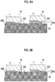
- Figs. 8A and 8B are views for comparison between the linear inclined portion 10C and the arcuate inclined portion 10C of the original 10 illustrated in Figs. 2A and 2B in the raised portion P formed on the end portion of the recessed pattern 20A of the surface 20B of the thermoplastic resin sheet 20.
- Figs. 8A and 8B only the part of the inclined portion 10C of the original 10 and the part of the thermoplastic resin sheet 20 corresponding to the inclined portion 10C are illustrated.
- Fig. 8A refers to the case of the linear inclined portion 10C
- the left figure of Fig. 8A is a view when the inclined portion 10C of the original 10 and the surface 20B of the thermoplastic resin sheet 20 are brought into close contact with each other by pressing
- the right figure is a view when the inclined portion 10C and the surface 20B are not in close contact with each other.
- Fig. 8B refers to the case of the arcuate inclined portion 10C
- the left figure of Fig. 8B is a view when the inclined portion 10C of the original 10 and the surface 20B of the thermoplastic resin sheet 20 are brought into close contact with each other by pressing
- the right figure is a view when the inclined portion 10C and the surface 20B are not in close contact with each other.
- a stepped portion is not formed in the linear inclined portion 10C or the arcuate inclined portion 10C.
- the stepped portion height W3 formed by the arcuate inclined portion 10C is smaller than the stepped portion height W4 formed by the linear inclined portion 10C.
- the stepped portion height W4 formed by the linear inclined portion 10C is smaller than the stepped portion height W2 in the case where the inclined portion 10C illustrated in Fig. 7B is absent.
- thermoplastic resin sheet 20 As a factor that causes the inclined portion 10C of the original 10 and the surface 20B of the thermoplastic resin sheet 20 not to come into close contact with each other, there is a case where the pressing stroke of the original 10 against the thermoplastic resin sheet 20 is unstable. In addition, there is a case where the thermoplastic resin sheet 20 is less likely to soften and the resin raised from the surface 20B of the thermoplastic resin sheet 20 is less likely to spread on the surface 20B. Therefore, in such cases, it is more preferable to use the original 10 having the arcuate inclined portion 10C.
- Figs. 9A and 9B view for comparison between the case where the flat portion 10D is absent at the inclination terminal of the linear inclined portion 10C ( Fig. 9A ) and the case where the flat portion 10D is present ( Fig. 9B ) in the raised portion P formed on the end portion of the recessed pattern 20A of the surface 20B of the thermoplastic resin sheet 20.
- Figs. 9A and 9B only the part of the inclined portion 10C of the original 10 and the part of the thermoplastic resin sheet 20 corresponding to the inclined portion 10C are illustrated.
- the stepped portion height W7 in the case where the flat portion 10D is present is slightly smaller than the stepped portion height W5 in the case where the flat portion 10D is absent, and there is no significant difference therebetween.
- the stepped portion height W8 in the case where the flat portion 10D is present is significantly smaller than the stepped portion height W6 in the case where the flat portion 10D is absent.
- the stepped portion height can be further reduced.
- thermoplastic resin sheet 20 Next, a control method when the original 10 is pressed against the thermoplastic resin sheet 20 will be described.
- Fig. 10 is a schematic configuration diagram illustrating an example of a pressing apparatus 30 having an alignment function.
- the pressing apparatus 30 includes a Z-axis drive mechanism 32 which drives the original 10 in a Z-axis direction, a connection portion 34 connected to the Z-axis drive mechanism 32, a holding portion 36 attached to the connection portion 34, a table 38 which supports the thermoplastic resin sheet 20, an X-axis drive mechanism 40 which drives the table 38 in an X-axis direction, a Y-axis drive mechanism 42 which drives the table 38 in a Y-axis direction, a stand 44, a control system 46, and a laser displacement meter 48.
- the original 10 is held by the holding portion 36, for example, by adsorption.
- a first control method in a case where alignment between the original 10 and the pressing position of the thermoplastic resin sheet 20 is necessary as in a case where the original 10 is pressed against a plurality of points of the thermoplastic resin sheet 20, first, the X-axis drive mechanism 40 and the Y-axis drive mechanism 42 are driven to align the original 10 and the thermoplastic resin sheet 20 with each other.
- the position of the surface 20B of the thermoplastic resin sheet 20 is measured. That is, before moving the original 10 in the pressing direction, for example, the control system 46 measures the distance between the protruding pattern 10A of the original 10 and the surface 20B of the thermoplastic resin sheet 20 by using the laser displacement meter 48. By measuring the distance, the position of the surface 20B of the thermoplastic resin sheet 20 can be detected.
- the control system 46 determines the amount of the protruding pattern 10A pushed from the position of the surface 20B of the thermoplastic resin sheet 20.
- the control system 46 drives the Z-axis drive mechanism 32, and the Z-axis drive mechanism 32 moves the original 10 to the position of the surface 20B of the thermoplastic resin sheet 20 and further pushes the original 10 toward the thermoplastic resin sheet 20 side by a certain amount (the pushing amount determined). Accordingly, the protruding pattern 10A is pushed into the thermoplastic resin sheet 20 up to the set pushing position of the protruding pattern 10A, and thus the inclined portion 10C of the original 10 and the surface 20B of the thermoplastic resin sheet 20 are brought into close contact with each other.
- the X-axis drive mechanism 40 and the Y-axis drive mechanism 42 are first driven to align the original 10 and the thermoplastic resin sheet 20 with each other.
- the control system 46 drives the Z-axis drive mechanism 32, and the Z-axis drive mechanism 32 moves the original 10 to the position of the surface 20B of the thermoplastic resin sheet 20.
- the pressure applied to the original 10 is measured while the original 10 is moved by the Z-axis drive mechanism 32.
- the pressure measurement method is not particularly limited.
- a load cell may be disposed between the original 10 and the holding portion 36, and the pressure applied to the original 10 may be measured by the load cell.
- the load cell is a measuring instrument that can measure a compressive force in the thickness direction thereof.
- the control system 46 compares the measured pressure with a preset pressure. When the measured pressure reaches the preset pressure, the control system 46 determines that the protruding pattern 10A has reached the surface 20B of the thermoplastic resin sheet 20.
- the control system 46 determines the amount of the protruding pattern 10A pushed from the position of the surface 20B of the thermoplastic resin sheet 20.
- the control system 46 drives the Z-axis drive mechanism 32 to push the original 10 toward the thermoplastic resin sheet 20 by a certain amount (the pushing amount determined). Accordingly, the protruding pattern 10A is pushed into the thermoplastic resin sheet 20 up to the set pushing position of the protruding pattern 10A, and thus the inclined portion 10C of the original 10 and the surface 20B of the thermoplastic resin sheet 20 are brought into close contact with each other.
- the X-axis drive mechanism 40 and the Y-axis drive mechanism 42 are first driven to align the original 10 and the thermoplastic resin sheet 20 with each other.
- the control system 46 drives the Z-axis drive mechanism 32, and the Z-axis drive mechanism 32 moves the original 10 to the position of the surface 20B of the thermoplastic resin sheet 20.
- the pressure applied to the original 10 is measured while the original 10 is moved by the Z-axis drive mechanism 32.
- the control system 46 compares the measured pressure with a preset pressure.
- the relationship between the pressure applied to the original 10 and the amount (depth) of the protruding pattern 10A pushed into the thermoplastic resin sheet 20 is previously obtained.
- the control system 46 compares the measured pressure with a preset pressure. When the measured pressure reaches the set pressure, the control system 46 determines that the protruding pattern 10A has reached a desired pushing amount from the surface 20B of the thermoplastic resin sheet 20. In this embodiment, the control system 46 calculates the pushing amount from the previously obtained relationship based on the measured pressure.
- the original 10 is not pushed into the thermoplastic resin sheet 20. That is, the control system 46 measures a pressure applied to the original 10, compares the measured pressure with a certain pressure value which is set, and determines the pushing amount of the original 10 as "0".
- the control system 46 determines the amount of the protruding pattern 10A of the original 10 pushed into the thermoplastic resin sheet 20 based on the current position of the original 10.
- the control system 46 drives the Z-axis drive mechanism 32 to push the original 10 toward the thermoplastic resin sheet 20 by a certain amount (the pushing amount determined). Accordingly, the protruding pattern 10A is pushed into the thermoplastic resin sheet 20 up to the set pushing position of the protruding pattern 10A, and thus the inclined portion 10C of the original 10 and the surface 20B of the thermoplastic resin sheet 20 are brought into close contact with each other.
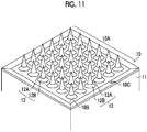
- Fig. 11 illustrates the original 10 in which the shape of the protrusion 12 is different from that in Fig. 1 .
- the protrusion 12 included in the protruding pattern 10A illustrated in Fig. 11 is constituted by the frustum portion 12B and the needle portion 12A which is tapered in the direction away from one flat surface 10B of the base 11.
- the frustum portion 12B includes a square frustum, a circular cone frustum, and the like. Another frustum portion may be included between the frustum portion 12B and the needle portion 12A.
- the inclined portion 10C which is formed in an enclosed shape on the outer peripheral portion of the protruding pattern 10A and gradually increases in thickness from the inside toward the outside up to the set pushing position of the protruding pattern 10A is formed.
- the protrusion 12 preferably has a height of 100 to 2000 ⁇ m from the flat surface 10B of the original 10 and has a tip diameter of ⁇ 50 ⁇ m or less.
- the interval between adjacent protrusions 12 is 300 to 2000 ⁇ m.
- the aspect ratio (the height of the protrusion / the width of the bottom surface of the protrusion) of the protrusion 12 is 1 to 5.
- the ratio of the height of the needle portion 12A to the height of the frustum portion 12B (the height of the needle portion 12A / the height of the frustum portion 12B) is preferably 1 to 10.
- the angle between the side surface of the frustum portion 12B and the flat surface 10B is preferably 10° to 60°.
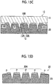
- Figs. 12A and 12B are vertical sectional views of the original 10 having the protrusions 12 in Fig. 11
- Fig. 12A refers to a case where the linear inclined portion 10C is provided
- Fig. 12B refers to a case where the arcuate inclined portion 10C is provided.
- Figs. 12A and 12B are conceptual views of the original 10, and Figs. 12A and 12B and Fig. 11 are different from each other in the number of protrusions 12 constituting the protruding pattern 10A.
- the flat portion 10D as illustrated in Fig. 3A may be provided to be connected to the inclination terminal of the linear inclined portion 10C in Fig. 12A
- the flat portion 10D as illustrated in Fig. 3B may be provided to be connected to the inclination terminal of the arcuate inclined portion 10C in Fig. 12B .
- the protrusion 12 included in the protruding pattern 10A of the original 10 illustrated in Fig. 13 is constituted by the frustum portion 12B, a columnar portion 12C, and the needle portion 12A which is tapered in the direction away from the flat surface 10B.
- the columnar portion 12C means a shape having two opposing parallel bottom surfaces, as represented by a cylinder or a rectangular parallelepiped, in which the areas of the two bottom surfaces are the same.
- an inclined portion which is formed in an enclosed shape on the outer peripheral portion of the protruding pattern 10A and gradually increases in thickness from the inside toward the outside up to the set pushing position of the protruding pattern 10A is formed.
- the protrusion 12 preferably has a height of 100 to 2000 ⁇ m from the flat surface 10B of the original 10 and has a tip diameter of ⁇ 50 ⁇ m or less.
- the interval between adjacent protrusions 12 is 300 to 2000 ⁇ m.
- the aspect ratio (the height of the protrusion / the width of the bottom surface of the protrusion) of the protrusion 12 is 1 to 5.
- the ratio of the total height of the needle portion 12A and the columnar portion 12C to the height of the frustum portion 12B is preferably 1 to 10.
- the ratio of the height of the needle portion 12A to the height of the columnar portion 12C (the height of the needle portion 12A / the height of the columnar portion 12C) is preferably 0.25 to 10.
- the angle between the side surface of the needle portion 12A and the flat surface 10B is preferably 45° to 85°.
- the angle between the side surface of the frustum portion 12B and the flat surface 10B is preferably 10° to 60°.
- Figs. 14A and 14B are vertical sectional views of the original 10 having the protrusions 12 in Fig. 13
- Fig. 14A refers to a case where the linear inclined portion 10C is provided
- Fig. 14B refers to a case where the arcuate inclined portion 10C is provided.
- Figs. 14A and 14B are conceptual views of the original 10, and Figs. 14A and 14B and Fig. 13 are different from each other in the number of protrusions 12 constituting the protruding pattern 10A.
- the flat portion 10D as illustrated in Fig. 3A may be provided to be connected to the inclination terminal of the linear inclined portion 10C in Fig. 14A
- the flat portion 10D as illustrated in Fig. 3B may be provided to be connected to the inclination terminal of the arcuate inclined portion 10C in Fig. 14B .
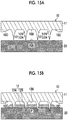
- Figs. 15A to 15D show a process of producing the mold 22 using the original 10 having a combination of the protruding pattern 10A having the protrusions 12 constituted by the frustum portion 12B and the needle portion 12A in Fig. 11 and the arcuate inclined portion 10C.
- Fig. 15A is a preparation process of preparing the original 10 and the thermoplastic resin sheet 20.
- Figs. 15B to 15D show a forming process of forming the recessed pattern 20A on the thermoplastic resin sheet 20 by pressing the original 10 against the surface 20B side of the thermoplastic resin sheet 20, and thereafter cooling and peeling the original 10.
- Fig. 15B is a view illustrating the protrusions 12 constituting the protruding pattern 10A of the original 10, which are pushed into the thermoplastic resin sheet 20 up to the middle of the protrusions 12.
- the protruding pattern 10A is further pushed until the inclined portion 10C of the original 10 and the surface 20B of the thermoplastic resin sheet 20 are brought into close contact with each other.
- the surface 20B of the thermoplastic resin sheet 20 is further raised and fills all the spaces 13 described above.
- the shape of the protrusion 12 is constituted by the needle portion 12A and the frustum portion 12B, the raised portions P on the surface 20B of the thermoplastic resin sheet 20 receive a force spreading in the horizontal direction from the frustum portion 12B.
- the raised portions P are more likely to spread toward the inclination terminal of the inclined portion 10C provided in the original 10, thereby further preventing the generation of the stepped portion.
- the original 10 is cooled until the thermoplastic resin sheet 20 is cooled to the softening temperature or lower.
- the original 10 and the thermoplastic resin sheet 20 are separated from each other, thereby forming the recessed pattern 20A having the inverted shape of the protruding pattern 10A on the surface 20B side of the thermoplastic resin sheet 20. Accordingly, the mold 22 is produced.
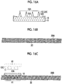
- Fig. 16A illustrates a process of preparing the original 10, and an example in which the original 10 described with reference to Fig. 2A is used will be described. That is, the original 10 has one protruding pattern 10A formed at the center portion on one flat surface 10B and the linear inclined portion 10C formed on the outer peripheral portion of the protruding pattern 10A.
- Fig. 16B illustrates a preparation process of preparing the large thermoplastic resin sheet 20.
- the thermoplastic resin sheet 20 as the material of the mold 22 is prepared, and the thermoplastic resin sheet 20 is set, for example, on the table (not illustrated).
- the large thermoplastic resin sheet 20 has a thickness of, for example, 0.5 to 2.0 mm and a size of 100 ⁇ 100 to 300 ⁇ 300, and has the surface 20B against which the protruding pattern 10A of the original 10 to be pressed. A plurality of recessed patterns 20A to be described later are formed on the surface 20B side.
- Figs. 16C and 16D show an alignment process, the forming process of forming the recessed pattern 20A, the alignment process and the forming process which are repeatedly performed.
- a position for example, a region A1 at which the original 10 is pressed against the thermoplastic resin sheet 20 is determined by moving the prepared original 10 and the thermoplastic resin sheet 20 relative to each other.
- the pressing apparatus 30 having the alignment function illustrated in Fig. 10 may be used. That is, the alignment is performed by moving the table 38 that supports the thermoplastic resin sheet 20 using the X-axis drive mechanism 40 and the Y-axis drive mechanism 42 which move in directions perpendicular to each other on the horizontal plane.
- thermoplastic resin sheet 20 For accurate alignment, for example, it is preferable to provide alignment marks for alignment on the surface 20B of the thermoplastic resin sheet 20. Furthermore, in order to detect the original 10, the thermoplastic resin sheet 20, and the alignment marks, it is preferable to provide an imaging device or the like.
- the heated original 10 is pressed against the surface 20B side of the thermoplastic resin sheet 20 by the Z-axis drive mechanism 32 of the pressing apparatus 30.
- the protruding pattern 10A of the original 10 is pressed against the thermoplastic resin sheet 20, and the surface 20B of the thermoplastic resin sheet 20 is raised.
- the raised portion of the surface 20B of the thermoplastic resin sheet 20 corresponding to the inclined portion 10C of the original 10 decreases in thickness from the inside toward the outside.
- the raised portion P is strictly present, the illustration thereof is omitted here.
- the generation of the stepped portion at the end portion of the surface 20B of the thermoplastic resin sheet 20 (a part indicated by the circle in Fig. 16C ) can be prevented. Even if a stepped portion is generated, the stepped portion can be made extremely small.
- thermoplastic resin sheet 20 is heated for a certain period of time.
- the original 10 is cooled until the thermoplastic resin sheet 20 is cooled to the softening temperature or lower.
- the original 10 and the thermoplastic resin sheet 20 are separated from each other, thereby forming the recessed pattern 20A having the inverted shape of the protruding pattern 10A on the surface 20B side of the thermoplastic resin sheet 20.
- the separation of the original 10 from the thermoplastic resin sheet 20 can be performed by the above-described Z-axis drive mechanism 32.
- the recessed pattern 20A in the region A1 in Fig. 16D is completed, alignment (here, a region A2) between the original 10 and the thermoplastic resin sheet 20 is performed.
- the heated original 10 is pressed against the surface 20B side of the thermoplastic resin sheet 20.
- the protruding pattern 10A of the original 10 is pressed against the surface 20B side of the thermoplastic resin sheet 20.
- the flat surface 10B of the original 10 and the surface 20B of the thermoplastic resin sheet 20 are separated from each other.
- the side of the surface 20B of the thermoplastic resin sheet 20 is heated for a certain period of time.
- the original 10 is cooled until the thermoplastic resin sheet 20 is cooled to the softening temperature or lower.
- the original 10 and the thermoplastic resin sheet 20 are separated from each other, thereby forming the recessed pattern 20A having the inverted shape of the protruding pattern 10A on the surface 20B side of the thermoplastic resin sheet 20.
- thermoplastic resin sheet 20 Furthermore, alignment (here, a region A3) between the original 10 and the thermoplastic resin sheet 20 is performed, and the heated original 10 is pressed against the surface 20B of the thermoplastic resin sheet 20.
- thermoplastic resin sheet 20 when the formation of the predetermined recessed pattern 20A on the surface 20B side of the thermoplastic resin sheet 20 is completed, the large mold 22 having a plurality of the recessed patterns 20A from the thermoplastic resin sheet 20 is produced.
- Fig. 17 is a perspective view of the mold 22 produced according to Figs. 16A to 16E and the original 10 having one protruding pattern 10A used for the mold 22.
- the mold 22 which has 3 ⁇ 3 recessed patterns 20A and is made of a resin is produced using the original 10 having one protruding pattern 10A.
- the mold 22 which has 3 ⁇ 3 recessed patterns 20A and is made of a resin is produced, a large original having 3 ⁇ 3 protruding patterns is not produced. Therefore, in this embodiment, the number of operations for producing the original 10 can be reduced.
- the mold 22 which has 3 ⁇ 3 recessed patterns 20A and is made of a resin is exemplified, the number of recessed patterns 20A is appropriately determined.
- the mold 22 is produced using the original 10 having the inclined portion 10C, the generation of the stepped portion between adjacent recessed patterns 20A (for example, S1 and S2) can be prevented. Even if a stepped portion is generated, the stepped portion can be made extremely small. Accordingly, when a polymer sheet 210 is peeled away from the mold 22, the stepped portion does not become peeling resistance, and thus the polymer sheet 210 can be easily peeled away. Therefore, peeling failure such as breaking of the polymer sheet 210 does not occur.
- FIGS. 18A to 18G are process diagrams illustrating a procedure of the manufacturing method of a pattern sheet using the large mold 22.
- Fig. 18A illustrates a state in which the mold 22 is prepared.
- the mold 22 is produced by the production method of a mold described above, and the plurality of recessed patterns 20A are formed on the surface 20B of the mold 22.
- Fig. 18B illustrates a supplying process of supplying a polymer solution to the plurality of recessed patterns 20A of the mold 22.
- a polymer solution 200 is prepared.
- a material of the resin polymer used for the polymer solution 200 it is preferable to use a biocompatible resin.
- a biocompatible resin As such resins, sugars such as glucose, maltose, pullulan, sodium chondroitin sulfate, sodium hyaluronate, hydroxyethyl starch, and hydroxypropyl cellulose, proteins such as gelatin and biodegradable polymers such as polylactic acid and a lactic acid-glycolic acid copolymer are preferably used.
- gelatin-based materials have adhesion to many base materials and have a strong gel strength when used as a gelating material
- the gelatin-based materials can be brought into close contact with a base material in the peeling process, which will be described later, and a polymer sheet can be peeled away from the mold 22 using the base material, so that the gelatin-based materials can be suitably used.
- a drug may be contained in the polymer solution 200.
- the drug to be contained in the polymer solution 200 is not particularly limited as long as the drug is a substance having a physiological activity.
- the drug is preferably selected from peptides, proteins, nucleic acids, polysaccharides, vaccines, pharmaceutical compounds, or cosmetic ingredients.
- the pharmaceutical compound belongs to a water-soluble low molecular weight compound.
- the low molecular weight compound is a compound having a molecular weight range of several hundreds to several thousands.
- the concentration varies depending on the material, it is preferable that the concentration is set so that the resin polymer is contained at 10 to 50 mass% in the polymer solution 200 which does not contain the drug.
- the solvent used for dissolution may be warm water or may be volatile, and methyl ethyl ketone, alcohol, or the like may be used. And, it is possible to dissolve the drug, which is supplied into the body according to the application, in the solution of the polymer resin.
- the polymer concentration of the polymer solution 200 containing the drug is preferably in a range of 0 to 40 mass%.
- a water-soluble polymer such as gelatin
- a water-soluble powder may be dissolved in water and the drug may be added after the dissolution. Otherwise, a powder of a water-soluble polymer may be dissolved in a liquid in which the drug is dissolved.
- heating may be performed for dissolution.
- the temperature can be appropriately selected depending on the kind of the polymer material, and it is preferable that heating is performed at a temperature of about 60°C or lower.
- the viscosity of the solution of the polymer resin is preferably 100 Pa ⁇ s or less, and more preferably 10 Pa ⁇ s or less.
- the viscosity is preferably 2000 Pa ⁇ s or less, and more preferably 1000 Pa ⁇ s or less.
- injecting the solution into a needle-like recess of a mold is facilitated.
- the viscosity of the solution of the polymer resin can be measured with a capillary viscometer, a falling ball viscometer, a rotational viscometer, or a vibrational viscometer.
- the polymer solution 200 is supplied to the mold 22 such that the plurality of recessed patterns 20A are filled with the polymer solution 200. That is, the recesses constituting the recessed patterns 20A are filled with the polymer solution 200.
- a method for filling the plurality of recessed patterns 20A with the polymer solution 200 As a method for filling the plurality of recessed patterns 20A with the polymer solution 200, a method of performing filling using a spin coater, a method of performing filling by moving a squeegee, a method of performing filling while moving a slit nozzle, a method of filling the recesses of the plurality of recessed patterns 20A using a dispenser, or the like may be employed.
- the polymer solution 200 is supplied to the plurality of recessed patterns 20A while moving the slit nozzle and the mold 22 relative to each other.
- the surface of the mold 22 preferably has flatness.
- the supplying process is preferably performed under an environment at reduced pressure.
- the environment at reduced pressure means a state at or below atmospheric pressure.
- the polymer solution 200 can be supplied to the tip end of the recessed pattern 20A while the air is released from the recess under the environment at reduced pressure. This is particularly effective in a case where the mold 22 is a gas permeable material.
- the mold 22 supplied with the polymer solution 200 is placed in a pressure vessel. After heating the inside of the pressure vessel to 40°C using a heating jacket, compressed air is injected into the pressure vessel from a compressor. The air in the recess is removed by holding the inside of the pressure vessel at a pressure of 0.5 MPa for 5 minutes and applying a pressure thereto, thereby enabling the polymer solution 200 to be supplied to the tip end of the recessed pattern 20A of the mold 22.
- Fig. 18C illustrates a drying process of drying the polymer solution 200 to form the polymer sheet 210.
- the polymer solution 200 supplied to the mold 22 can be dried by blowing air thereto.
- Drying is divided into, for example, four zones, and by setting conditions including (1) set dry at 15°C (low humidity, wind speed 4 m/sec), (2) light wind drying at 35°C (low humidity, wind speed 8 m/sec), (3) strong wind drying at 50°C (wind speed 12 m/sec), and (4) strong wind drying at 30°C (wind speed 20 m/sec), efficient drying can be performed.
- the polymer solution 200 can be gelated by flowing cold air at a low humidity. In order to completely gelate the polymer solution 200, cold air at 10 to 15 [°C] is blown for a longer period of time than in the above case, and thereafter air is blown in the same manner as above. In addition, in this case, when hot air at a high temperature is flowed for subsequent drying, if the temperature of hot air is too high, gelation of the polymer solution 200 is cancelled or the effect of the drug may change due to decomposition of the drug through heating. Therefore, the temperature of the blown air requires attention. As described above, the applied polymer solution 200 is dried, or the polymer solution 200 is gelated and dried to solidify, thereby obtaining the polymer sheet 210.
- the polymer sheet 210 is reduced in size compared to the state when the polymer solution 200 is injected. Particularly, in a case where gelation is performed, the polymer sheet 210 is significantly reduced in size. Accordingly, peeling of the polymer sheet 210 from the mold 22 described later is facilitated.
- the polymer sheet 210 means a state after a desired drying treatment is applied to the polymer solution 200.
- the moisture content of the polymer sheet 210 and the like are appropriately set.
- Figs. 18D and 18E illustrate a polymer sheet peeling process of peeling the polymer sheet 210 from the mold 22.
- a sheet-like base material 300 having a pressure sensitive adhesive layer formed thereon is attached to the surface of the polymer sheet 210 opposite to the mold 22.
- the surface of the base material 300 may be subjected to a surface activation treatment so as to be bonded.
- the polymer solution may be applied thereto from above the base material 300 to bury the base material 300 therein.
- a material of the sheet-like base material 300 for example, polyethylene terephthalate (PET), polypropylene (PP), polycarbonate (PC), or polyethylene (PE), may be used.
- the base material 300 and the polymer sheet 210 are simultaneously peeled away.
- a sucker (not illustrated) is placed on the surface of the base material 300 opposite to the bonding surface of the polymer sheet 210, and is pulled up vertically while sucking the base material 300 with air.
- the polymer sheet 210 is peeled away from the mold 22, thereby forming a pattern sheet 220 having a protruding pattern 220A.
- the material forming the mold 22 is made of a material which can be very easily peeled away. Furthermore, by using a highly elastic and soft material as the material forming the mold 22, stress applied to the protruding pattern 220A of the pattern sheet 220 during peeling can be relieved.
- the protruding pattern 220A of the pattern sheet 220 has the inverted shape of the recessed pattern 20A of the mold 22.
- the pattern sheet 220 is basically the same as the polymer sheet 210 peeled away from the mold 22.
- Figs. 18F and 18G illustrate a cutting process of cutting the pattern sheet 220 into the individual pattern sheets 220.
- the pattern sheet 220 having the protruding pattern 220A and the base material 300 peeled away from the mold 22 are set in a cutting device (not illustrated).
- the positions to cut the pattern sheet 220 are determined. Basically, the cutting position is determined for each protruding pattern 220A.
- the pattern sheet 220 is cut into a plurality of the individual pattern sheets 220.
- the example in which the pattern sheet 220 and the base material 300 are simultaneously cut is described, but the present invention is not limited thereto.
- the base material 300 may be peeled away from the pattern sheet 220 and the base material 300 peeled away from the mold 22, and the pattern sheet 220 may be cut into the individual pattern sheets 220.
- the present invention is not limited thereto.
- a polymer sheet can be formed by filling the recessed pattern 20A with the polymer solution 200 containing the drug, drying the polymer solution 200, filling the recessed pattern 20A with the polymer solution 200 which does not contain a drug, and drying the polymer solution 200.
- the number of times the polymer solution 200 is supplied and the presence or absence of the drug in the polymer solution 200 can be appropriately changed.
- Fig. 19 is a perspective view of the individual pattern sheet 220.
- the individual pattern sheet 220 has the protruding pattern 220A on one surface.
- the pattern sheet 220 has the base material 300 on the surface opposite to the surface on which the protruding pattern 220A is formed.
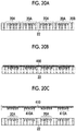
- FIGs. 20A to 20C are process diagrams illustrating a procedure of the production method of an electroform using the mold 22.
- Fig. 20A illustrates a state in which the mold 22 is prepared.
- the mold 22 is produced by the above-described production method of the mold 22, and the recessed pattern 20A is formed on the surface 20B of the mold 22.
- Fig. 20B is a process diagram illustrating an electroforming process in which metal is buried in the recessed pattern 20A of the mold 22 by an electroforming method.
- a conduction treatment is performed on the mold 22.
- Metal for example, nickel
- the mold 22 subjected to the conduction treatment is held at a cathode.
- Metal pellets are held in a metallic case as an anode.
- the cathode holding the mold 22 and the anode holding the metal pellets are immersed in an electroforming liquid to cause electricity to flow.
- the metal is buried in the recessed pattern 20A of the mold 22 by the electroforming method, thereby forming a metal body 400.
- the electroforming method refers to a method of depositing metal on the surface of a mold by an electroplating method.
- Fig. 20C is a process diagram illustrating a peeling process of peeling the metal body 400 from the mold 22.
- the metal body 400 is peeled away from the mold 22, thereby producing an electroform 410 having a protruding pattern 410A. Peeling means the separation of the metal body 400 from the mold 22.
- the protruding pattern 410A has the inverted shape of the recessed pattern 20A of the mold 22.
- the electroform 410 is basically the same as the metal body 400 peeled away from the mold 22.
- the mold 22 is produced using the original 10 illustrated in Fig. 1
- the electroform 410 is produced using the mold 22 illustrated in Figs. 20A to 20C . Therefore, the electroform 410 having a larger area than the original 10 can be obtained.
- the electroform 410 has the same function as the original 10 and has a larger area than the original 10. That is, since an original having a large area can be obtained by an electroforming method other than machining such as grinding, the costs for producing the original having a large area can be reduced.
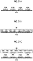
- FIGs. 21A to 21C are process diagrams illustrating a procedure of the production method of the mold 26 using the electroform 410.
- Fig. 21A illustrates a state in which the electroform 410 is prepared.
- the electroform 410 is produced by the above-described production method of the electroform 410.
- the electroform 410 has the protruding pattern 410A on one side.
- Figs. 21B and 21C are process diagrams illustrating a process of producing a mold 26 which has an recessed patterns 26A which has the inverted shape of the protruding pattern 410A of the electroform 410 and is made of a resin, by using the electroform 410 having the protruding pattern 410A.
- the recessed pattern 26A refers to a state in which recesses extending from one surface of the mold 26 toward the other surface are disposed on one surface of the mold 26.
- the number of recesses, the positions of the disposed recesses, and the like are not limited.
- the mold 26 having the recessed pattern 26A can be produced by the following first to third methods.
- An ultraviolet curable resin which is cured by being irradiated with ultraviolet rays is prepared.
- the protruding pattern 410A of the electroform 410 is pressed against the ultraviolet curable resin.
- the ultraviolet curable resin is irradiated with ultraviolet rays such that the ultraviolet curable resin is cured.
- the electroform 410 is peeled away from the ultraviolet curable resin which is cured.
- the mold 26 having the recessed pattern 26A which has the inverted shape of the protruding pattern 410A of the electroform 410 and is made of the resin can be produced.
- thermoplastic resin sheet as the material of the mold 26 is prepared.
- the electroform 410 having the protruding pattern 410A is heated.
- the protruding pattern 410A of the heated electroform 410 is pressed against the surface of the thermoplastic resin sheet. Since the surface of the thermoplastic resin is softened, the protruding pattern 410A is transferred onto the thermoplastic resin sheet.
- thermoplastic resin sheet In the state in which the electroform 410 is pressed against the thermoplastic resin sheet, the thermoplastic resin sheet and the electroform 410 are cooled. The thermoplastic resin sheet is cured by cooling the electroform 410. Thereafter, the electroform 410 is peeled away from the thermoplastic resin sheet to which the protruding pattern 410A has been transferred.
- the mold 26 having the recessed pattern 26A which has the inverted shape of the protruding pattern 410A of the electroform 410 and is made of the resin can be produced.
- a silicone resin is prepared by adding a hardener to PDMS (polydimethylsiloxane, for example, SYLGARD 184 manufactured by Dow Corning Corporation).
- the protruding pattern 410A of the electroform 410 is pressed against the silicone resin.
- the silicone resin is heated and cured at 100°C.
- the electroform 410 is peeled away from the cured silicone resin.
- the mold 26 having the recessed pattern 26A which has the inverted shape of the protruding pattern 410A of the electroform 410 and is made of the resin can be produced.
- the size of each recess of the recessed pattern 26A is substantially the same as the size of the protrusion of the protruding pattern 410A.
- the method of producing the mold 26 is not limited to the first to third methods.
- Figs. 22A to 22G are process diagrams illustrating a procedure of the manufacturing method of the pattern sheet 220 using the mold 26.
- the process diagrams illustrating the procedure of the manufacturing method of the pattern sheet in Figs. 18A to 18G and the process diagrams illustrating the procedure of the manufacturing method of the pattern sheet in Figs. 22A to 22G are basically the same except for the difference between the mold 22 and the mold 26. Therefore, like configurations which are similar to those of the process diagrams illustrated in Figs. 18A to 18G are denoted by like reference numerals, and the description thereof may be omitted in some cases.
- Fig. 22A illustrates a state in which the mold 26 is prepared. As illustrated in Figs. 21A to 21C described above, the mold 26 is produced using the electroform 410. The mold 26 has the recessed pattern 26A on one side.
- Fig. 22B illustrates a supplying process of supplying the polymer solution 200 to the recessed pattern 26A of the mold 26.
- the polymer solution 200 is basically the same as the polymer solution 200 described with reference to Figs. 18A to 18G .
- the polymer solution 200 is supplied to the mold 26 such that the recessed pattern 26A is filled with the polymer solution 200. That is, the recesses constituting the recessed pattern 26A are filled with the polymer solution 200.
- the filling methods described with reference to Figs. 18A to 18G may be applied.
- Fig. 22C illustrates a drying process of drying the polymer solution 200 to form the polymer sheet 210.
- the polymer solution 200 supplied to the mold 26 can be dried by blowing air thereto.
- the drying method, conditions, and the like described with reference to Figs. 18A to 18G can be applied.
- Figs. 22D and 22E illustrate a polymer sheet peeling process of peeling the polymer sheet 210 from the mold 26.
- the sheet-like base material 300 having a pressure sensitive adhesive layer formed thereon is attached to the surface of the polymer sheet 210 opposite to the mold 26.
- the base material 300 and the polymer sheet 210 are simultaneously peeled away.
- a sucker (not illustrated) is placed on the surface of the base material 300 opposite to the bonding surface of the polymer sheet 210, and is pulled up vertically while sucking the base material 300 with air.
- the polymer sheet 210 is peeled away from the mold 26, thereby forming the pattern sheet 220 having the protruding pattern 220A.
- the material forming the mold 26 is made of a material which can be very easily peeled away. Furthermore, by using a highly elastic and soft material as the material forming the mold 26, stress applied to the protruding pattern 220A of the pattern sheet 220 during peeling can be relieved.
- the protruding pattern 220A of the pattern sheet 220 has the inverted shape of the recessed pattern 26A of the mold 26.
- the pattern sheet 220 is basically the same as the polymer sheet 210 peeled away from the mold 26.
- Figs. 22F and 22G illustrate a cutting process of cutting the pattern sheet 220 into the individual pattern sheets 220.
- the pattern sheet 220 having the protruding pattern 220A and the base material 300 peeled away from the mold 26 are set in a cutting device (not illustrated).
- the positions to cut the pattern sheet 220 are determined. Basically, the cutting position is determined for each protruding pattern 220A.
- the pattern sheet 220 is cut into a plurality of the individual pattern sheets 220.
- the example in which the pattern sheet 220 and the base material 300 are simultaneously cut is described, but the present invention is not limited thereto.
- the base material 300 may be peeled away from the pattern sheet 220 and the base material 300 peeled away from the mold 26, and the pattern sheet 220 may be cut into the individual pattern sheets 220.
- the present invention is not limited thereto.
- a polymer sheet can be formed by filling the recessed pattern 20A with the polymer solution 200 containing the drug, drying the polymer solution 200, filling the recessed pattern 20A with the polymer solution 200 which does not contain a drug, and drying the polymer solution 200.
- the number of times the polymer solution 200 is supplied and the presence or absence of the drug in the polymer solution 200 can be appropriately changed.
- the generation of a stepped portion between recessed patterns can be prevented, and even if a stepped portion is generated, the stepped portion can be made extremely small.
- the number of operations of producing the original can be reduced, and the productivity can be improved.
Description
- The present invention relates to a production method of a mold, a manufacturing method of a pattern sheet, a production method of an electroform, a production method of a mold using an electroform, and an original.
- In recent years, as a novel dosage form capable of injecting drugs such as insulin, vaccines, and human growth hormone (hGH) into the skin without pain, a microneedle array has been known. The microneedle array is an array of microneedles (also referred to as fine needles or small needles) which contain drugs and are biodegradable. By attaching this microneedle array to the skin, each microneedle pierces the skin, these microneedles are absorbed in the skin such that the drugs contained in each microneedle can be administered into the skin. Microneedle arrays are also called percutaneous absorption sheets.
- In order to produce a formed product having a fine protruding pattern like the microneedle array as described above, a resin mold having the inverted shape is formed from an original having a fine protruding pattern, and a formed product is produced from the mold. There is a demand for improving the productivity of formed products having fine patterns, and various proposals have been made.
-
JP2007-535343A JP2007-535343A -
JP2011-083993A JP2011-083993A - In the technique described in
JP2007-535343A - In the technique described in
JP2011-083993A - The present invention has been made taking the above circumstances into consideration, and an object thereof is to provide a production method of a mold, a manufacturing method of a pattern sheet, a production method of an electroform, a production method of a mold using an electroform, and an original capable of preventing peeling failure during production of a duplicate product or formed product from a mold and improving the releasability of the original itself by preventing the generation of a stepped portion at an end portion of a recessed pattern of the surface of the mold.
- According to an aspect of the present invention, there is provided a production method of a mold comprising: a preparation process of preparing an original having an inclined portion which is formed in an enclosed shape on an outer peripheral portion of a protruding pattern formed at a center portion on a base and gradually increases in thickness from the inside toward the outside, and a thermoplastic resin sheet; and a forming process of forming a recessed pattern having an inverted shape of the protruding pattern on the thermoplastic resin sheet by pressing the original which is heated against the thermoplastic resin sheet at a position where the inclined portion of the original and a surface of the thermoplastic resin sheet are in close contact with each other, cooling the original in the state in which the original is pressed, and separating the original from the thermoplastic resin sheet.
- Accordingly, the generation of a stepped portion at the end portion of the recessed pattern of the surface of the produced mold can be prevented.
- In a preferred aspect of the present invention, it is preferable that an alignment process of determining a position at which the original is to be pressed against the thermoplastic resin sheet by moving the original and the thermoplastic resin sheet relative to each other, and the forming process are repeatedly performed. Accordingly, the generation of a stepped portion between the recessed patterns can be prevented, and a large mold having a plurality of the recessed patterns with a single original can be produced.
- In a preferred aspect of the present invention, it is preferable that the inclined portion has a vertical sectional shape formed in a right-angled triangle such that the thickness thereof linearly increases from the inside toward the outside. Accordingly, the generation of a stepped portion can be prevented.
- In a preferred aspect of the present invention, it is preferable that the inclined portion has a vertical sectional shape formed in an arcuate shape such that the thickness thereof increases in an arc shape from the inside toward the outside and thereafter the increase in thickness gradually decreases. Accordingly, the generation of a stepped portion can be further prevented.
- In a preferred aspect of the present invention, the original has a flat portion which is formed to be connected to an inclination terminal of the inclined portion.
- It is preferable that, when the original is pressed against the thermoplastic resin sheet, a position of the surface of the thermoplastic resin sheet is detected, and the original is pushed from the position of the surface of the thermoplastic resin sheet by a certain amount.
- It is preferable that, when the original is pressed against the thermoplastic resin sheet, a pressure applied to the original is measured and is compared to a certain pressure value which is set, and the amount of the original being pushed is determined.
- According to another aspect of the present invention, there is provided a manufacturing method of a pattern sheet having a protruding pattern, comprising: a process of producing a mold using the above-described production method; a supplying process of supplying a polymer solution to a recessed pattern of the mold; a drying process of drying the polymer solution to form a polymer sheet; and a polymer sheet peeling process of peeling the polymer sheet from the mold.
- According to another aspect of the present invention, there is provided a production method of an electroform having a protruding pattern, comprising: a process of producing a mold using the above-described production method; an electroforming process of forming a metal body on a recessed pattern of the mold by an electroforming method; and a peeling process of peeling the metal body from the mold.
- According to another aspect of the present invention, there is provided a production method of a mold, comprising: a process of producing an electroform using the above-described production method; and a process of, by using the electroform having a protruding pattern, producing a mold which has a recessed pattern which is an inverted shape of the protruding pattern of the electroform and is made of a resin.
- According to another aspect of the present invention, there is provided a manufacturing method of a pattern sheet having a protruding pattern, comprising: a process of producing a mold using the production method of an electroform described above; a supplying process of supplying a polymer solution to a recessed pattern of the mold; a drying process of drying the polymer solution to form a polymer sheet; and a peeling process of peeling the polymer sheet from the mold.
- According to an aspect of the present invention, there is provided an original which is pressed against a surface of a thermoplastic resin sheet to transfer a protruding pattern onto the thermoplastic resin sheet, the original comprising: an inclined portion which is formed in an enclosed shape on an outer peripheral portion of the protruding pattern formed at a center portion on a base and gradually increases in thickness from the inside toward the outside.
- Accordingly, when a mold is produced using the original, the generation of a stepped portion at the end portion of a recessed pattern of the surface of the mold can be prevented, and the peeling property of the original itself is also improved.
- Furthermore, a preferred aspect of the original further comprises a flat portion which is formed to be connected to an inclination terminal of the inclined portion.
- According to the production method of a mold, the manufacturing method of a pattern sheet, the production method of an electroform, the production method of a mold using an electroform, and the original of the present invention, the generation of a stepped portion at the end portion of the recessed pattern of the mold can be prevented.
- Accordingly, peeling failure during production of a duplicate product or formed product from a mold can be prevented, and the releasability of the original itself can be improved.
-
-
Fig. 1 is a perspective view illustrating an aspect of an original according to an embodiment of the present invention. -
Fig. 2A is a vertical sectional view of an original having a linear inclined portion. -
Fig. 2B is a vertical sectional view of the original having an arcuate inclined portion. -
Fig. 3A is a vertical sectional view of the original having a flat portion which is formed to be connected to an inclination terminal of the linear inclined portion. -
Fig. 3B is a vertical sectional view of the original having the flat portion which is formed to be connected to the inclination terminal of the arcuate inclined portion. -
Fig. 4A is an explanatory view illustrating a method of setting a maximum thickness D of an inclined portion of the original. -
Fig. 4B is another explanatory view illustrating the method of setting the maximum thickness D of the inclined portion of the original. -
Fig. 5A is a vertical sectional view illustrating the preparation of the original and a thermoplastic resin sheet in a production method of a mold. -
Fig. 5B is a vertical sectional view of the original which is pressed against the thermoplastic resin sheet up to the middle of the original in the production method of a mold. -
Fig. 5C is a vertical sectional view of the original which is pressed against the thermoplastic resin sheet until the original and the thermoplastic resin sheet are brought into close contact with each other in the production method of a mold. -
Fig. 5D is a vertical sectional view of a mold formed in the production method of a mold. -
Fig. 6A is a sectional view illustrating an end portion of the mold produced by using the original having the inclined portion. -
Fig. 6B is an enlarged sectional view of a part indicated by the circled inFig. 6A . -
Fig. 6C is a view illustrating peeling a duplicate product from the mold. -
Fig. 7A is a sectional view illustrating an end portion of a mold produced by using an original without an inclined portion. -
Fig. 7B is an enlarged sectional view of a part indicated by the circled inFig. 7A . -
Fig. 7C is a view illustrating peeling the duplicate product from the mold. -
Fig. 8A is a partial sectional view of a case where the linear inclined portion is in close contact with the surface of the thermoplastic resin sheet and a case where the linear inclined portion and the surface of the thermoplastic resin sheet are not in close contact with each other. -
Fig. 8B is a partial sectional view of a case where the arcuate inclined portion is in close contact with the surface of the thermoplastic resin sheet and a case where the arcuate inclined portion and the surface of the thermoplastic resin sheet are not in close contact with each other. -
Fig. 9A is a partial sectional view of a case where a flat portion which is formed to be connected to the inclination terminal of the linear inclined portion is absent. -
Fig. 9B is a partial sectional view of a case where the flat portion which is formed to be connected to the inclination terminal of the linear inclined portion is present. -
Fig. 10 is a configuration diagram illustrating the overall configuration of a pressing apparatus. -
Fig. 11 is a perspective view of an original according to another aspect of the present invention, in which the original has protrusions different from those inFig. 1 . -
Fig. 12A is a sectional view of the original having the protrusions inFig. 10 and having the linear inclined portion. -
Fig. 12B is a sectional view of the original having the protrusions inFig. 10 and having the arcuate inclined portion. -
Fig. 13 is a perspective view of an original according to still another aspect of the present invention, in which the original has protrusions different from those inFig. 1 . -
Fig. 14A is a sectional view of the original having the protrusions inFig. 13 and having the linear inclined portion. -
Fig. 14B is a sectional view of the original having the protrusions inFig. 13 and having the arcuate inclined portion. -
Fig. 15A is a sectional view illustrating preparation of the original inFig. 12B and the thermoplastic resin sheet in the production method of a mold. -
Fig. 15B is a sectional view of the original which is pressed against the thermoplastic resin sheet up to the middle of the original in the production method of a mold. -
Fig. 15C is a sectional view of the original which is pressed against the thermoplastic resin sheet until the original and the thermoplastic resin sheet are brought into close contact with each other in the production method of a mold. -
Fig. 15D is a sectional view of a mold formed in the production method of a mold. -
Fig. 16A is a sectional view illustrating preparation of an original in a production method of a large mold. -
Fig. 16B is a sectional view illustrating preparation of a thermoplastic resin sheet in the production method of a large mold. -
Fig. 16C is a sectional view illustrating the original which is pressed against a region of the thermoplastic resin sheet in the production method of a large mold. -
Fig. 16D is a sectional view illustrating the original which is pressed against another region of the thermoplastic resin sheet in the production method of a large mold. -
Fig. 16E is a sectional view of a mold produced in the production method of a large mold. -
Fig. 17 is a perspective view of the original having one protruding pattern and the thermoplastic resin sheet having a plurality of recessed patterns. -
Fig. 18A is a diagram illustrating preparation of a mold in a process procedure of a manufacturing method of a pattern sheet. -
Fig. 18B is a diagram illustrating supply of a polymer solution to a recessed pattern in the process procedure of the manufacturing method of a pattern sheet. -
Fig. 18C is a diagram illustrating drying of the polymer solution in the process procedure of the manufacturing method of a pattern sheet. -
Fig. 18D is a diagram illustrating a polymer sheet before being peeled away from the mold in the process procedure of the manufacturing method of a pattern sheet. -
Fig. 18E is a diagram illustrating the polymer sheet after being peeled away from the mold in the process procedure of the manufacturing method of a pattern sheet. -
Fig. 18F is a diagram illustrating the polymer sheet before being cut into individual pattern sheets in the process procedure of the manufacturing method of a pattern sheet. -
Fig. 18G is a diagram illustrating the polymer sheet after being cut into individual pattern sheets in the process procedure of the manufacturing method of a pattern sheet. -
Fig. 19 is a perspective view of the individual pattern sheet. -
Fig. 20A is a diagram illustrating preparation of a mold in a process procedure of a production method of an electroform using a mold. -
Fig. 20B is a diagram illustrating electroforming in the process procedure of the production method of an electroform using a mold. -
Fig. 20C is a diagram illustrating a metal body peeled away from the mold in the process procedure of the production method of an electroform using a mold. -
Fig. 21A is a diagram illustrating preparation of an electroform in a process procedure of a production method of a mold using an electroform. -
Fig. 21B is a diagram illustrating an ultraviolet curable resin which is pressed against the electroform in the process procedure of the production method of a mold using an electroform. -
Fig. 21C is a diagram illustrating the electroform which is peeled away from the ultraviolet curable resin cured in the process procedure of the production method of a mold using an electroform. -
Fig. 22A is a diagram illustrating preparation of mold in a process procedure of a production method of a pattern sheet using a mold produced using an electroform. -
Fig. 22B is a diagram illustrating supply of a polymer solution to a recessed pattern in the process procedure of the production method of a pattern sheet using a mold produced using an electroform. -
Fig. 22C is a diagram illustrating drying of the polymer solution in the process procedure of the production method of a pattern sheet using a mold produced using an electroform. -
Fig. 22D is a diagram illustrating a polymer sheet before being peeled away from the mold in the process procedure of the production method of a pattern sheet using a mold produced using an electroform. -
Fig. 22E is a diagram illustrating the polymer sheet after being peeled away from the mold in the process procedure of the production method of a pattern sheet using a mold produced using an electroform. -
Fig. 22F is a diagram illustrating the polymer sheet before being cut into individual pattern sheets in the process procedure of the production method of a pattern sheet using a mold produced using an electroform. -
Fig. 22G is a diagram illustrating the polymer sheet after being cut into individual pattern sheets in the process procedure of the production method of a pattern sheet using a mold produced using an electroform. - Hereinafter, preferred embodiments of the present invention will be described with reference to the accompanying drawings. The present invention is described by the following preferred embodiments.
- Modifications can be made by various methods without departing from the scope of the present invention, and other embodiments than this embodiment can also be used. Therefore, all modifications within the scope of the present invention are included in the appended claims.
- Here, in the figures, like elements having similar functions are denoted by like reference numerals. In addition, in this specification, in a case where a numerical value range is expressed using "to", the numerical value range includes the numerical values of the upper limit and the lower limit indicated by "to".
-
Fig. 1 is a perspective view illustrating a first embodiment of an original of the present invention. - As illustrated in
Fig. 1 , the first embodiment of the original 10 includes aprotruding pattern 10A formed at the center portion on oneflat surface 10B of abase 11, and aninclined portion 10C formed on the outer peripheral portion of theprotruding pattern 10A. - The original 10 having the protruding
pattern 10A and theinclined portion 10C is produced, for example, by machining a metal substrate, which is to become the original 10, using a cutting tool such as a diamond insert bite. As the metal substrate, stainless steel, an aluminum alloy, Ni, or the like may be used. - The protruding
pattern 10A of the original 10 is basically the same as the protruding pattern of a pattern sheet (a formed product such as a percutaneous absorption sheet) to be produced. The protrudingpattern 10A refers to a state in which aprotrusion 12 protruding in a direction away from theflat surface 10B of the original 10 is disposed on theflat surface 10B of the original 10. The number ofprotrusions 12 is not limited. Theflat surface 10B may be a perfectly flat surface or may be a flat surface at first glance. - As illustrated in
Fig. 1 , in this embodiment, theprotrusion 12 is constituted by aneedle portion 12A which is tapered in the direction away from theflat surface 10B. Theprotrusion 12 is a so-called cone, and the cone includes a pyramid, a circular cone, and the like. - For example, the
protrusion 12 preferably has a height of 100 to 2000 µm from theflat surface 10B of the original 10 and has a tip diameter of Φ50 µm or less. In the case where a plurality of theprotrusions 12 are provided, it is preferable that the interval betweenadjacent protrusions 12 is 300 to 2000 µm. It is preferable that the aspect ratio (the height of the protrusion / the width of the bottom surface of the protrusion) of theprotrusion 12 is 1 to 5. - The
inclined portion 10C is formed in an enclosed shape on the outer peripheral portion of theprotruding pattern 10A formed at the center portion on theflat surface 10B and gradually increases in thickness from the inside (the center side of theflat surface 10B) toward the outside (the end portion side of theflat surface 10B). - The thickness of the
inclined portion 10C can be referred to as the height of theinclined portion 10C. -
Figs. 2A and 2B show two preferable embodiments in which the thickness of theinclined portion 10C gradually increases. - The
inclined portion 10C inFig. 2A has a vertical sectional shape formed in a right-angled triangle such that the thickness thereof linearly increases from the inside (the center portion side) toward the outside (the periphery portion side) of theflat surface 10B (hereinafter, referred to as a linear inclined portion). Furthermore, theinclined portion 10C inFig. 2B has a vertical sectional shape formed in an arcuate shape such that the thickness thereof increases in an arc shape from the inside toward the outside of theflag surface 10B and thereafter the increase in thickness gradually decreases, that is, the thickness increases so-called arcuately (hereinafter, referred to as an arcuate inclined portion). The term "a vertical sectional shape formed in an arcuate shape" means, when a horizontal oval shape is divided into four equal parts by a vertical line and a horizontal line passing through the center, the sectional shape of one divided part. -
Figs. 3A and 3B are perspective views illustrating a second embodiment of the original 10 of the present invention. - The second embodiment of the original 10 includes the
protruding pattern 10A formed at the center portion on oneflat surface 10B of thebase 11, theinclined portion 10C formed on the outer peripheral portion of theprotruding pattern 10A, and aflat portion 10D which is formed to be connected to the inclination terminal of theinclined portion 10C. - Here, the inclination terminal refers to a terminal where the thickness of the
inclined portion 10C gradually increases to the maximum thickness D and the inclination ends. Therefore, theflat portion 10D is formed to have the same thickness as the maximum thickness D of theinclined portion 10C. - The original 10 in
Fig. 3A refers to a case where theflat portion 10D is formed to be connected to the inclination terminal of the linearinclined portion 10C. The original 10 inFig. 3B refers to a case where theflat portion 10D is formed to be connected to the inclination terminal of the arcuateinclined portion 10C. The protrudingpattern 10A of the original 10 is the same as the protrudingpattern 10A of the first embodiment. - The maximum thickness D of the
inclined portion 10C of the original 10 is set as follows. - Since the case of the linear
inclined portion 10C (Fig. 2A ), the case of the arcuateinclined portion 10C (Fig. 2B ), the case where theflat portion 10D connected to the inclination terminal of the linearinclined portion 10C is provided (Fig. 3A ), and the case where theflat portion 10D connected to the inclination terminal of the arcuateinclined portion 10C is provided (Fig. 3B ) have the same method of setting the maximum thickness D of theinclined portion 10C, the case of the linearinclined portion 10C will now be described as an example. -
Fig. 4A is a vertical sectional view illustrating the original 10 which is pressed against asurface 20B side of athermoplastic resin sheet 20 such that the plurality of protrusions 12 (12A) of theprotruding pattern 10A are pushed into thethermoplastic resin sheet 20 until the part of the linearinclined portion 10C having the maximum thickness D comes into close contact with thesurface 20B of thethermoplastic resin sheet 20. - The original 10 is an example in which a total of 16 protrusions 12 (12A) are arranged in a two-dimensional array of 4 rows and 4 columns in the
protruding pattern 10A, and theinclined portion 10C is formed in an enclosed shape the outer peripheral portion of theprotruding pattern 10A.Fig. 4A is a vertical sectional view of theprotruding pattern 10A, and theprotrusions 12 are also formed in the forward and rearward directions ofFig. 4A . In addition,Fig. 4A is a vertical sectional view conceptually illustrating the original 10, andFig. 4A andFig. 1 are different from each other in the number ofprotrusions 12 constituting the protrudingpattern 10A. - The maximum thickness D of the
inclined portion 10C is set so that the total volume (X1 + X2 + X3 + X4 + ... + X16) of the parts (mesh parts inFig. 4A ) of the 16 protrusions 12 (12A) constituting the protrudingpattern 10A, which are pushed into thethermoplastic resin sheet 20, is equal to the total volume (Y1 + Y2 + Y3 + Y4 + Y5 + ... + Y25) of spaces 13 (white parts inFig. 4A ) enclosed by theflat surface 10B of the original 10, thesurface 20B of thethermoplastic resin sheet 20, and theinclined portion 10C. In a case where a total of 16 protrusions 12 (12A) are arranged in a two-dimensional array of 4 rows and 4 columns as the protrudingpattern 10A, 25spaces 13 are formed. -
Fig. 4B is a vertical sectional view illustrating the protrudingpattern 10A, in which the shape of theprotrusion 12 is constituted by theneedle portion 12A and afrustum portion 12B, being pushed into thethermoplastic resin sheet 20 until the part of the linearinclined portion 10C having the maximum thickness D comes into close contact with thesurface 20B of thethermoplastic resin sheet 20.Fig. 4B refers to a case where theneedle portion 12A and a part of thefrustum portion 12B are pushed into thethermoplastic resin sheet 20. - Even in this case, the maximum thickness D of the
inclined portion 10C is set so that the total volume (X1 + X2 + X3 + X4 + ... + X16) of the parts (mesh parts inFig. 4B ) pushed into thethermoplastic resin sheet 20 is equal to the total volume (Y1 + Y2 + Y3 + Y4 + Y5 + ... + Y25) of the spaces 13 (white parts inFig. 4B ) enclosed by theflat surface 10B of the original 10, thesurface 20B of thethermoplastic resin sheet 20, and theinclined portion 10C. - That is, the maximum thickness D of the
inclined portion 10C is set so that all the raised parts on thesurface 20B of thethermoplastic resin sheet 20 corresponding to the total volume (X1 + X2 + X3 + X4 + ... + X16) of the pushed parts of theprotruding pattern 10A can be accommodated in the total volume (Y1 + Y2 + Y3 + Y4 + Y5 + ... + Y25) of thespaces 13, regardless of the shape (linear shape, or arcuate shape) of theinclined portion 10C, the presence or absence of theflat portion 10D, and the shape of theprotrusion 12. - [Embodiment of Production Method of Mold] An embodiment of a production method of a mold of the present invention using the above-described original 10 will be described using the original 10 having the linear
inclined portion 10C inFig. 2A as an example. -
Figs. 5A to 5D are process diagrams illustrating a procedure of the production method of a mold. -
Fig. 5A illustrates a preparation process of preparing the original 10, and thethermoplastic resin sheet 20 which is the material of the mold. - The
thermoplastic resin sheet 20 is set, for example, on a table (not illustrated). Thethermoplastic resin sheet 20 has a thickness of 0.5 to 2.0 mm, for example, and has thesurface 20B. A recessed pattern, which will be described later, is formed on thesurface 20B side. It is preferable that the thickness of thethermoplastic resin sheet 20 is equal to or greater than at least the height of theprotrusion 12 of the original 10. - The thermoplastic resin forming the
thermoplastic resin sheet 20 is not particularly limited. For example, polyethylene terephthalate, polycarbonate, polymethyl methacrylate, polystyrene, polyethylene, a liquid crystal polymer, and polylactic acid may be suitably used. - The
thermoplastic resin sheet 20 means a thermoplastic resin in a state of having a small film thickness and a self-supporting property at room temperature. "Self-supporting property" means that a single body can hold its form without the support of other members. -
Figs. 5B to 5D show a forming process of forming a recessedpattern 20A on thethermoplastic resin sheet 20 by pressing the original 10 against thesurface 20B side of thethermoplastic resin sheet 20, and thereafter cooling and peeling the original 10. - As illustrated in
Fig. 5B , the original 10 which is heated is pressed against thesurface 20B side of thethermoplastic resin sheet 20. The original 10 is heated to a temperature at which thethermoplastic resin sheet 20 is softened. Heating is performed by a heater (not illustrated). The original 10 is heated to an appropriate temperature depending on the thermoplastic resin forming thethermoplastic resin sheet 20. - Accordingly, the protruding
pattern 10A of the original 10 is pushed into thethermoplastic resin sheet 20.Fig.5B is a view illustrating theprotrusions 12 constituting the protrudingpattern 10A of the original 10, which are pushed into thethermoplastic resin sheet 20 up to the middle of theprotrusions 12. By pushing the protrudingpattern 10A, thesurface 20B of thethermoplastic resin sheet 20 is raised by the volume corresponding to the total volume of the pushed parts of the protrusions 12 (12A), such that raised portions P are formed. - In
Figs. 5B to 5D , thethermoplastic resin sheet 20 is indicated by diagonal lines and the raised portions P are indicated by meshes. However, this is for clearly indicating the raised portions P, and there is no distinction therebetween in appearance. - As illustrated in
Fig. 5C , the original 10 which is further heated is pressed against thesurface 20B of thethermoplastic resin sheet 20, and theprotruding pattern 10A is pushed into thethermoplastic resin sheet 20 until theinclined portion 10C of the original 10 comes into close contact with thesurface 20B of thethermoplastic resin sheet 20. - In addition, while pressing the heated original 10, the side of the
surface 20B of thethermoplastic resin sheet 20 is heated for a certain period of time. - By pushing the protruding
pattern 10A, thesurface 20B of thethermoplastic resin sheet 20 is further raised and fills all thespaces 13 described above. The total volume of thespaces 13 is adjusted by the sizes of the raised portions P on thesurface 20B of thethermoplastic resin sheet 20, that is, the total volume of the pushed parts of theprotruding pattern 10A and the maximum thickness D of theinclined portion 10C. - Next, in the state in which the original 10 is pressed against the
thermoplastic resin sheet 20, the original 10 is cooled until thethermoplastic resin sheet 20 is cooled to the softening temperature or lower. - Last, as illustrated in
Fig. 5D , the original 10 and thethermoplastic resin sheet 20 are peeled away from each other, thereby forming the recessedpattern 20A having the inverted shape of theprotruding pattern 10A on thesurface 20B side of thethermoplastic resin sheet 20. Accordingly, amold 22 is produced. - The recessed
pattern 20A refers to a state in which recesses extending from thesurface 20B of thethermoplastic resin sheet 20 toward the other surface are disposed on thesurface 20B side of thethermoplastic resin sheet 20. The number of recesses, the arrangement of the recesses, the depth of the recesses, and the like are not limited. Since the recessedpattern 20A is the inverted shape of theprotruding pattern 10A, the size, number, and arrangement of the recesses of the recessedpattern 20A are basically the same as those of theprotrusions 12 pushed into thethermoplastic resin sheet 20. - As described above, as the protruding
pattern 10A of the original 10 presses thethermoplastic resin sheet 20, the surface of thethermoplastic resin sheet 20 is raised. - However, as illustrated in the enlarged view of the produced
mold 22 inFig. 6A and the end portion (a part enclosed by the circle inFig. 6A ) of the recessedpattern 20A inFig. 6B , the raised portion P of the end portion of thethermoplastic resin sheet 20 corresponding to theinclined portion 10C of the original 10 decreases in thickness from the inside toward the outside. Accordingly, the generation of a stepped portion at the end portion (peripheral portion) of the recessedpattern 20A of the producedmold 22 can be prevented. Even if a stepped portion is formed, as illustrated inFig. 6B , the stepped portion height W1 can be made extremely small. - Therefore, as illustrated in
Fig. 6C , themold 22 produced by the production method of the mold of this embodiment does not cause the stepped portion to become peeling resistance when a duplicate mold 23 (or formed product) is peeled away from themold 22 in the process of producing the duplicate mold 23 (or formed product). Accordingly, the duplicate mold 23 (or formed product) can be easily peeled away from themold 22, and peeling failure such as breaking of the duplicate mold 23 (or formed product) at the stepped portion during peeling can be prevented. - Moreover, since the
inclined portion 10C is provided in the original 10, releasability of the original 10 itself can be improved when themold 22 is produced from the original 10. - Contrary to this,
Figs. 7A to 7C refer to a case where the duplicate mold 23 (formed product) is produced using themold 22 produced using the original 10 without theinclined portion 10C. - As illustrated in the enlarged view of the produced
mold 22 inFig. 7A and the end portion (a part enclosed by the circle inFig. 7A ) of the recessedpattern 20A inFig. 7B , the raised portion P ends while the raised portion P of the end portion of thethermoplastic resin sheet 20 does not decrease in thickness from the inside toward the outside and maintains the same thickness. Accordingly, a stepped portion at a substantially right angle is formed at the end position of the raised portion P, that is, the end portion (peripheral portion) of the recessedpattern 20A. As illustrated inFig. 7B , the stepped portion height W2 of the stepped portion at a substantially right angle, which is formed on the end portion (peripheral part) of the recessedpattern 20A is significantly larger than the stepped portion height W1 in the case where theinclined portion 10C illustrated inFig. 7B is provided. - Therefore, as illustrated in
Fig. 7C , themold 22 produced using the original 10 without theinclined portion 10C causes the stepped portion to become resistance when the duplicate mold 23 (or formed product) is peeled away from themold 22 in the process of producing the duplicate mold 23 (or formed product) such that the duplicate mold 23 (or formed product) cannot be easily peeled away and peeling failure such as breaking at the stepped portion is more likely to occur. -
Figs. 8A and 8B are views for comparison between the linearinclined portion 10C and the arcuateinclined portion 10C of the original 10 illustrated inFigs. 2A and 2B in the raised portion P formed on the end portion of the recessedpattern 20A of thesurface 20B of thethermoplastic resin sheet 20. InFigs. 8A and 8B , only the part of theinclined portion 10C of the original 10 and the part of thethermoplastic resin sheet 20 corresponding to theinclined portion 10C are illustrated. -
Fig. 8A refers to the case of the linearinclined portion 10C, the left figure ofFig. 8A is a view when theinclined portion 10C of the original 10 and thesurface 20B of thethermoplastic resin sheet 20 are brought into close contact with each other by pressing, and the right figure is a view when theinclined portion 10C and thesurface 20B are not in close contact with each other.Fig. 8B refers to the case of the arcuateinclined portion 10C, the left figure ofFig. 8B is a view when theinclined portion 10C of the original 10 and thesurface 20B of thethermoplastic resin sheet 20 are brought into close contact with each other by pressing, and the right figure is a view when theinclined portion 10C and thesurface 20B are not in close contact with each other. - As can be seen from the left figure of
Fig. 8A and the left figure ofFig. 8B , in the case where theinclined portion 10C of the original 10 and thesurface 20B of thethermoplastic resin sheet 20 are in close contact with each other, a stepped portion is not formed in the linearinclined portion 10C or the arcuateinclined portion 10C. Contrary to this, as can be seen from the right figure ofFig. 8A and the right figure ofFig. 8B , in the case where theinclined portion 10C of the original 10 and thesurface 20B of thethermoplastic resin sheet 20 are not in close contact with each other, the stepped portion height W3 formed by the arcuateinclined portion 10C is smaller than the stepped portion height W4 formed by the linearinclined portion 10C. - However, the stepped portion height W4 formed by the linear
inclined portion 10C is smaller than the stepped portion height W2 in the case where theinclined portion 10C illustrated inFig. 7B is absent. - As a factor that causes the
inclined portion 10C of the original 10 and thesurface 20B of thethermoplastic resin sheet 20 not to come into close contact with each other, there is a case where the pressing stroke of the original 10 against thethermoplastic resin sheet 20 is unstable. In addition, there is a case where thethermoplastic resin sheet 20 is less likely to soften and the resin raised from thesurface 20B of thethermoplastic resin sheet 20 is less likely to spread on thesurface 20B. Therefore, in such cases, it is more preferable to use the original 10 having the arcuateinclined portion 10C. -
Figs. 9A and 9B view for comparison between the case where theflat portion 10D is absent at the inclination terminal of the linearinclined portion 10C (Fig. 9A ) and the case where theflat portion 10D is present (Fig. 9B ) in the raised portion P formed on the end portion of the recessedpattern 20A of thesurface 20B of thethermoplastic resin sheet 20. InFigs. 9A and 9B , only the part of theinclined portion 10C of the original 10 and the part of thethermoplastic resin sheet 20 corresponding to theinclined portion 10C are illustrated. - As can be seen from the left figure of
Fig. 9A and the left figure ofFig. 9B , in a case where the raised portion P on thesurface 20B of thethermoplastic resin sheet 20 spreads to a position HI close to the inclination terminal of theinclined portion 10C of the original 10, the stepped portion height W7 in the case where theflat portion 10D is present is slightly smaller than the stepped portion height W5 in the case where theflat portion 10D is absent, and there is no significant difference therebetween. - Contrary to this, as can be seen from the right figure of
Fig. 9A and the right figure ofFig. 9B , in a case where the raised portion P on thesurface 20B of thethermoplastic resin sheet 20 does not spread to a position H2 distant from the inclination terminal of theinclined portion 10C of the original 10, the stepped portion height W8 in the case where theflat portion 10D is present is significantly smaller than the stepped portion height W6 in the case where theflat portion 10D is absent. - That is, in the case where the
thermoplastic resin sheet 20 is less likely to soften and the resin raised from thesurface 20B of thethermoplastic resin sheet 20 is less likely to spread on thesurface 20B, by providing theflat portion 10D at the inclination terminal of theinclined portion 10C, the stepped portion height can be further reduced. - Next, a control method when the original 10 is pressed against the
thermoplastic resin sheet 20 will be described. -
Fig. 10 is a schematic configuration diagram illustrating an example of apressing apparatus 30 having an alignment function. As illustrated inFig. 10 , thepressing apparatus 30 includes a Z-axis drive mechanism 32 which drives the original 10 in a Z-axis direction, aconnection portion 34 connected to the Z-axis drive mechanism 32, a holdingportion 36 attached to theconnection portion 34, a table 38 which supports thethermoplastic resin sheet 20, anX-axis drive mechanism 40 which drives the table 38 in an X-axis direction, a Y-axis drive mechanism 42 which drives the table 38 in a Y-axis direction, astand 44, acontrol system 46, and alaser displacement meter 48. In addition, the original 10 is held by the holdingportion 36, for example, by adsorption. - According to a first control method, in a case where alignment between the original 10 and the pressing position of the
thermoplastic resin sheet 20 is necessary as in a case where the original 10 is pressed against a plurality of points of thethermoplastic resin sheet 20, first, theX-axis drive mechanism 40 and the Y-axis drive mechanism 42 are driven to align the original 10 and thethermoplastic resin sheet 20 with each other. In addition, when the heated original 10 is pressed against thethermoplastic resin sheet 20, the position of thesurface 20B of thethermoplastic resin sheet 20 is measured. That is, before moving the original 10 in the pressing direction, for example, thecontrol system 46 measures the distance between theprotruding pattern 10A of the original 10 and thesurface 20B of thethermoplastic resin sheet 20 by using thelaser displacement meter 48. By measuring the distance, the position of thesurface 20B of thethermoplastic resin sheet 20 can be detected. - On the basis of the measured distance, the
control system 46 determines the amount of theprotruding pattern 10A pushed from the position of thesurface 20B of thethermoplastic resin sheet 20. Thecontrol system 46 drives the Z-axis drive mechanism 32, and the Z-axis drive mechanism 32 moves the original 10 to the position of thesurface 20B of thethermoplastic resin sheet 20 and further pushes the original 10 toward thethermoplastic resin sheet 20 side by a certain amount (the pushing amount determined). Accordingly, the protrudingpattern 10A is pushed into thethermoplastic resin sheet 20 up to the set pushing position of theprotruding pattern 10A, and thus theinclined portion 10C of the original 10 and thesurface 20B of thethermoplastic resin sheet 20 are brought into close contact with each other. - According to a second control method, in a case where the alignment described above is necessary, the
X-axis drive mechanism 40 and the Y-axis drive mechanism 42 are first driven to align the original 10 and thethermoplastic resin sheet 20 with each other. Thecontrol system 46 drives the Z-axis drive mechanism 32, and the Z-axis drive mechanism 32 moves the original 10 to the position of thesurface 20B of thethermoplastic resin sheet 20. The pressure applied to the original 10 is measured while the original 10 is moved by the Z-axis drive mechanism 32. The pressure measurement method is not particularly limited. For example, a load cell may be disposed between the original 10 and the holdingportion 36, and the pressure applied to the original 10 may be measured by the load cell. The load cell is a measuring instrument that can measure a compressive force in the thickness direction thereof. - The
control system 46 compares the measured pressure with a preset pressure. When the measured pressure reaches the preset pressure, thecontrol system 46 determines that theprotruding pattern 10A has reached thesurface 20B of thethermoplastic resin sheet 20. - The
control system 46 determines the amount of theprotruding pattern 10A pushed from the position of thesurface 20B of thethermoplastic resin sheet 20. Thecontrol system 46 drives the Z-axis drive mechanism 32 to push the original 10 toward thethermoplastic resin sheet 20 by a certain amount (the pushing amount determined). Accordingly, the protrudingpattern 10A is pushed into thethermoplastic resin sheet 20 up to the set pushing position of theprotruding pattern 10A, and thus theinclined portion 10C of the original 10 and thesurface 20B of thethermoplastic resin sheet 20 are brought into close contact with each other. - According to a third control method, in a case where the alignment described above is necessary, the
X-axis drive mechanism 40 and the Y-axis drive mechanism 42 are first driven to align the original 10 and thethermoplastic resin sheet 20 with each other. Thecontrol system 46 drives the Z-axis drive mechanism 32, and the Z-axis drive mechanism 32 moves the original 10 to the position of thesurface 20B of thethermoplastic resin sheet 20. The pressure applied to the original 10 is measured while the original 10 is moved by the Z-axis drive mechanism 32. - The
control system 46 compares the measured pressure with a preset pressure. In the third control method, the relationship between the pressure applied to the original 10 and the amount (depth) of theprotruding pattern 10A pushed into thethermoplastic resin sheet 20 is previously obtained. - The
control system 46 compares the measured pressure with a preset pressure. When the measured pressure reaches the set pressure, thecontrol system 46 determines that theprotruding pattern 10A has reached a desired pushing amount from thesurface 20B of thethermoplastic resin sheet 20. In this embodiment, thecontrol system 46 calculates the pushing amount from the previously obtained relationship based on the measured pressure. - In a case where the pushing amount calculated from the pressure is the desired pushing amount with respect to the
thermoplastic resin sheet 20, the original 10 is not pushed into thethermoplastic resin sheet 20. That is, thecontrol system 46 measures a pressure applied to the original 10, compares the measured pressure with a certain pressure value which is set, and determines the pushing amount of the original 10 as "0". - In a case where the pushing amount calculated from the pressure is smaller than the desired pushing amount with respect to the
thermoplastic resin sheet 20, thecontrol system 46 determines the amount of theprotruding pattern 10A of the original 10 pushed into thethermoplastic resin sheet 20 based on the current position of the original 10. Thecontrol system 46 drives the Z-axis drive mechanism 32 to push the original 10 toward thethermoplastic resin sheet 20 by a certain amount (the pushing amount determined). Accordingly, the protrudingpattern 10A is pushed into thethermoplastic resin sheet 20 up to the set pushing position of theprotruding pattern 10A, and thus theinclined portion 10C of the original 10 and thesurface 20B of thethermoplastic resin sheet 20 are brought into close contact with each other. - According to the above-described control methods, it becomes possible to push the original 10 into the
thermoplastic resin sheet 20 with an accurate pressing stroke. In addition, the original 10 and thethermoplastic resin sheet 20 can be separated from each other by the above-described Z-axis drive mechanism 32. - Next, regarding the original 10 having the protruding
pattern 10A and theinclined portion 10C, the original 10 having a different shape from that of theprotrusions 12 constituting the protrudingpattern 10A illustrated inFig. 1 will be described. -
Fig. 11 illustrates the original 10 in which the shape of theprotrusion 12 is different from that inFig. 1 . Theprotrusion 12 included in theprotruding pattern 10A illustrated inFig. 11 is constituted by thefrustum portion 12B and theneedle portion 12A which is tapered in the direction away from oneflat surface 10B of thebase 11. Thefrustum portion 12B includes a square frustum, a circular cone frustum, and the like. Another frustum portion may be included between thefrustum portion 12B and theneedle portion 12A. In addition, theinclined portion 10C which is formed in an enclosed shape on the outer peripheral portion of theprotruding pattern 10A and gradually increases in thickness from the inside toward the outside up to the set pushing position of theprotruding pattern 10A is formed. - For example, the
protrusion 12 preferably has a height of 100 to 2000 µm from theflat surface 10B of the original 10 and has a tip diameter of Φ50 µm or less. In the case where a plurality of theprotrusions 12 are provided, it is preferable that the interval betweenadjacent protrusions 12 is 300 to 2000 µm. It is preferable that the aspect ratio (the height of the protrusion / the width of the bottom surface of the protrusion) of theprotrusion 12 is 1 to 5. - The ratio of the height of the
needle portion 12A to the height of thefrustum portion 12B (the height of theneedle portion 12A / the height of thefrustum portion 12B) is preferably 1 to 10. The angle between the side surface of thefrustum portion 12B and theflat surface 10B is preferably 10° to 60°. -
Figs. 12A and 12B are vertical sectional views of the original 10 having theprotrusions 12 inFig. 11 ,Fig. 12A refers to a case where the linearinclined portion 10C is provided, andFig. 12B refers to a case where the arcuateinclined portion 10C is provided. In addition,Figs. 12A and 12B are conceptual views of the original 10, andFigs. 12A and 12B andFig. 11 are different from each other in the number ofprotrusions 12 constituting the protrudingpattern 10A. - Furthermore, although not illustrated, the
flat portion 10D as illustrated inFig. 3A may be provided to be connected to the inclination terminal of the linearinclined portion 10C inFig. 12A , and theflat portion 10D as illustrated inFig. 3B may be provided to be connected to the inclination terminal of the arcuateinclined portion 10C inFig. 12B . - The
protrusion 12 included in theprotruding pattern 10A of the original 10 illustrated inFig. 13 is constituted by thefrustum portion 12B, acolumnar portion 12C, and theneedle portion 12A which is tapered in the direction away from theflat surface 10B. Here, thecolumnar portion 12C means a shape having two opposing parallel bottom surfaces, as represented by a cylinder or a rectangular parallelepiped, in which the areas of the two bottom surfaces are the same. In addition, an inclined portion which is formed in an enclosed shape on the outer peripheral portion of theprotruding pattern 10A and gradually increases in thickness from the inside toward the outside up to the set pushing position of theprotruding pattern 10A is formed. - For example, the
protrusion 12 preferably has a height of 100 to 2000 µm from theflat surface 10B of the original 10 and has a tip diameter of Φ50 µm or less. In the case where a plurality of theprotrusions 12 are provided, it is preferable that the interval betweenadjacent protrusions 12 is 300 to 2000 µm. It is preferable that the aspect ratio (the height of the protrusion / the width of the bottom surface of the protrusion) of theprotrusion 12 is 1 to 5. - The ratio of the total height of the
needle portion 12A and thecolumnar portion 12C to the height of thefrustum portion 12B (the total height of theneedle portion 12A and thecolumnar portion 12C / the height of thefrustum portion 12B) is preferably 1 to 10. In addition, the ratio of the height of theneedle portion 12A to the height of thecolumnar portion 12C (the height of theneedle portion 12A / the height of thecolumnar portion 12C) is preferably 0.25 to 10. The angle between the side surface of theneedle portion 12A and theflat surface 10B is preferably 45° to 85°. Furthermore, the angle between the side surface of thefrustum portion 12B and theflat surface 10B is preferably 10° to 60°. -
Figs. 14A and 14B are vertical sectional views of the original 10 having theprotrusions 12 inFig. 13 ,Fig. 14A refers to a case where the linearinclined portion 10C is provided, andFig. 14B refers to a case where the arcuateinclined portion 10C is provided. In addition,Figs. 14A and 14B are conceptual views of the original 10, andFigs. 14A and 14B andFig. 13 are different from each other in the number ofprotrusions 12 constituting the protrudingpattern 10A. - Furthermore, although not illustrated, the
flat portion 10D as illustrated inFig. 3A may be provided to be connected to the inclination terminal of the linearinclined portion 10C inFig. 14A , and theflat portion 10D as illustrated inFig. 3B may be provided to be connected to the inclination terminal of the arcuateinclined portion 10C inFig. 14B . -
Figs. 15A to 15D show a process of producing themold 22 using the original 10 having a combination of theprotruding pattern 10A having theprotrusions 12 constituted by thefrustum portion 12B and theneedle portion 12A inFig. 11 and the arcuateinclined portion 10C. -
Fig. 15A is a preparation process of preparing the original 10 and thethermoplastic resin sheet 20. -
Figs. 15B to 15D show a forming process of forming the recessedpattern 20A on thethermoplastic resin sheet 20 by pressing the original 10 against thesurface 20B side of thethermoplastic resin sheet 20, and thereafter cooling and peeling the original 10. - As illustrated in
Fig. 15B , the original 10 which is heated is pressed against thesurface 20B side of thethermoplastic resin sheet 20. Accordingly, the protrudingpattern 10A of the original 10 is pressed against thethermoplastic resin sheet 20.Fig. 15B is a view illustrating theprotrusions 12 constituting the protrudingpattern 10A of the original 10, which are pushed into thethermoplastic resin sheet 20 up to the middle of theprotrusions 12. By pushing the protrudingpattern 10A, thesurface 20B of thethermoplastic resin sheet 20 is raised by the volume corresponding to the total volume of the pushed parts of theprotrusions 12, such that raised portions P are formed. - Next, as illustrated in
Fig. 15C , the protrudingpattern 10A is further pushed until theinclined portion 10C of the original 10 and thesurface 20B of thethermoplastic resin sheet 20 are brought into close contact with each other. By pushing the protrudingpattern 10A, thesurface 20B of thethermoplastic resin sheet 20 is further raised and fills all thespaces 13 described above. At this time, since the shape of theprotrusion 12 is constituted by theneedle portion 12A and thefrustum portion 12B, the raised portions P on thesurface 20B of thethermoplastic resin sheet 20 receive a force spreading in the horizontal direction from thefrustum portion 12B. - Accordingly, compared to the case where the shape of the
protrusion 12 is constituted by only theneedle portion 12A, the raised portions P are more likely to spread toward the inclination terminal of theinclined portion 10C provided in the original 10, thereby further preventing the generation of the stepped portion. - Next, in the state in which the original 10 is pressed against the
thermoplastic resin sheet 20, the original 10 is cooled until thethermoplastic resin sheet 20 is cooled to the softening temperature or lower. - Last, as illustrated in
Fig. 15D , the original 10 and thethermoplastic resin sheet 20 are separated from each other, thereby forming the recessedpattern 20A having the inverted shape of theprotruding pattern 10A on thesurface 20B side of thethermoplastic resin sheet 20. Accordingly, themold 22 is produced. - [Production Method of Large Mold] Next, a process of producing the
large mold 22 having a plurality of the recessedpatterns 20A by pressing the original 10 having one protrudingpattern 10A against a plurality of points on thesurface 20B of the largethermoplastic resin sheet 20 will be described. -
Fig. 16A illustrates a process of preparing the original 10, and an example in which the original 10 described with reference toFig. 2A is used will be described. That is, the original 10 has one protrudingpattern 10A formed at the center portion on oneflat surface 10B and the linearinclined portion 10C formed on the outer peripheral portion of theprotruding pattern 10A. - Next,
Fig. 16B illustrates a preparation process of preparing the largethermoplastic resin sheet 20. Thethermoplastic resin sheet 20 as the material of themold 22 is prepared, and thethermoplastic resin sheet 20 is set, for example, on the table (not illustrated). - The large
thermoplastic resin sheet 20 has a thickness of, for example, 0.5 to 2.0 mm and a size of 100 × 100 to 300 × 300, and has thesurface 20B against which theprotruding pattern 10A of the original 10 to be pressed. A plurality of recessedpatterns 20A to be described later are formed on thesurface 20B side. -
Figs. 16C and16D show an alignment process, the forming process of forming the recessedpattern 20A, the alignment process and the forming process which are repeatedly performed. - First, a position (for example, a region A1) at which the original 10 is pressed against the
thermoplastic resin sheet 20 is determined by moving the prepared original 10 and thethermoplastic resin sheet 20 relative to each other. For the alignment, thepressing apparatus 30 having the alignment function illustrated inFig. 10 may be used. That is, the alignment is performed by moving the table 38 that supports thethermoplastic resin sheet 20 using theX-axis drive mechanism 40 and the Y-axis drive mechanism 42 which move in directions perpendicular to each other on the horizontal plane. - For accurate alignment, for example, it is preferable to provide alignment marks for alignment on the
surface 20B of thethermoplastic resin sheet 20. Furthermore, in order to detect the original 10, thethermoplastic resin sheet 20, and the alignment marks, it is preferable to provide an imaging device or the like. - Next, the heated original 10 is pressed against the
surface 20B side of thethermoplastic resin sheet 20 by the Z-axis drive mechanism 32 of thepressing apparatus 30. By the pressing, the protrudingpattern 10A of the original 10 is pressed against thethermoplastic resin sheet 20, and thesurface 20B of thethermoplastic resin sheet 20 is raised. - However, since the
inclined portion 10C is formed on the original 10, the raised portion of thesurface 20B of thethermoplastic resin sheet 20 corresponding to theinclined portion 10C of the original 10 decreases in thickness from the inside toward the outside. In addition, inFigs. 16C to 16E , although the raised portion P is strictly present, the illustration thereof is omitted here. - Accordingly, the generation of the stepped portion at the end portion of the
surface 20B of the thermoplastic resin sheet 20 (a part indicated by the circle inFig. 16C ) can be prevented. Even if a stepped portion is generated, the stepped portion can be made extremely small. - In addition, while pressing the heated original 10, the side of the
surface 20B of thethermoplastic resin sheet 20 is heated for a certain period of time. Next, in the state in which the original 10 is pressed against thethermoplastic resin sheet 20, the original 10 is cooled until thethermoplastic resin sheet 20 is cooled to the softening temperature or lower. - Next, as illustrated in
Fig. 16D , the original 10 and thethermoplastic resin sheet 20 are separated from each other, thereby forming the recessedpattern 20A having the inverted shape of theprotruding pattern 10A on thesurface 20B side of thethermoplastic resin sheet 20. The separation of the original 10 from thethermoplastic resin sheet 20 can be performed by the above-described Z-axis drive mechanism 32. - When the formation of the recessed
pattern 20A in the region A1 inFig. 16D is completed, alignment (here, a region A2) between the original 10 and thethermoplastic resin sheet 20 is performed. In the region A2, the heated original 10 is pressed against thesurface 20B side of thethermoplastic resin sheet 20. The protrudingpattern 10A of the original 10 is pressed against thesurface 20B side of thethermoplastic resin sheet 20. When the original 10 is pressed against thesurface 20B side of thethermoplastic resin sheet 20, theflat surface 10B of the original 10 and thesurface 20B of thethermoplastic resin sheet 20 are separated from each other. - In the region A2, while pressing the heated original 10, the side of the
surface 20B of thethermoplastic resin sheet 20 is heated for a certain period of time. Next, in the state in which the original 10 is pressed against thethermoplastic resin sheet 20, the original 10 is cooled until thethermoplastic resin sheet 20 is cooled to the softening temperature or lower. The original 10 and thethermoplastic resin sheet 20 are separated from each other, thereby forming the recessedpattern 20A having the inverted shape of theprotruding pattern 10A on thesurface 20B side of thethermoplastic resin sheet 20. - Furthermore, alignment (here, a region A3) between the original 10 and the
thermoplastic resin sheet 20 is performed, and the heated original 10 is pressed against thesurface 20B of thethermoplastic resin sheet 20. - The alignment process of the original 10 and the
thermoplastic resin sheet 20 and the forming process of forming the recessedpattern 20A having the inverted shape of theprotruding pattern 10A of the original 10 on thethermoplastic resin sheet 20, which are described with reference toFigs. 16C and16D , are repeated. - In addition, as illustrated in
Fig. 16E , when the formation of the predetermined recessedpattern 20A on thesurface 20B side of thethermoplastic resin sheet 20 is completed, thelarge mold 22 having a plurality of the recessedpatterns 20A from thethermoplastic resin sheet 20 is produced. -
Fig. 17 is a perspective view of themold 22 produced according toFigs. 16A to 16E and the original 10 having one protrudingpattern 10A used for themold 22. - As illustrated in
Fig. 17 , themold 22 which has 3 × 3 recessedpatterns 20A and is made of a resin is produced using the original 10 having one protrudingpattern 10A. In this embodiment, when themold 22 which has 3 × 3 recessedpatterns 20A and is made of a resin is produced, a large original having 3 × 3 protruding patterns is not produced. Therefore, in this embodiment, the number of operations for producing the original 10 can be reduced. Although themold 22 which has 3 × 3 recessedpatterns 20A and is made of a resin is exemplified, the number of recessedpatterns 20A is appropriately determined. - Furthermore, in this embodiment, since the
mold 22 is produced using the original 10 having theinclined portion 10C, the generation of the stepped portion between adjacent recessedpatterns 20A (for example, S1 and S2) can be prevented. Even if a stepped portion is generated, the stepped portion can be made extremely small. Accordingly, when apolymer sheet 210 is peeled away from themold 22, the stepped portion does not become peeling resistance, and thus thepolymer sheet 210 can be easily peeled away. Therefore, peeling failure such as breaking of thepolymer sheet 210 does not occur. - [Manufacturing Method of Pattern Sheet] Next, a manufacturing method of a pattern sheet having a protruding pattern which is a formed product having a fine pattern using the
large mold 22 produced as described above will be described.Figs. 18A to 18G are process diagrams illustrating a procedure of the manufacturing method of a pattern sheet using thelarge mold 22. -
Fig. 18A illustrates a state in which themold 22 is prepared. Themold 22 is produced by the production method of a mold described above, and the plurality of recessedpatterns 20A are formed on thesurface 20B of themold 22. -
Fig. 18B illustrates a supplying process of supplying a polymer solution to the plurality of recessedpatterns 20A of themold 22. - First, a
polymer solution 200 is prepared. As a material of the resin polymer used for thepolymer solution 200, it is preferable to use a biocompatible resin. As such resins, sugars such as glucose, maltose, pullulan, sodium chondroitin sulfate, sodium hyaluronate, hydroxyethyl starch, and hydroxypropyl cellulose, proteins such as gelatin and biodegradable polymers such as polylactic acid and a lactic acid-glycolic acid copolymer are preferably used. Among these, since gelatin-based materials have adhesion to many base materials and have a strong gel strength when used as a gelating material, the gelatin-based materials can be brought into close contact with a base material in the peeling process, which will be described later, and a polymer sheet can be peeled away from themold 22 using the base material, so that the gelatin-based materials can be suitably used. - Furthermore, a drug may be contained in the
polymer solution 200. The drug to be contained in thepolymer solution 200 is not particularly limited as long as the drug is a substance having a physiological activity. The drug is preferably selected from peptides, proteins, nucleic acids, polysaccharides, vaccines, pharmaceutical compounds, or cosmetic ingredients. I addition, it is preferable that the pharmaceutical compound belongs to a water-soluble low molecular weight compound. Here, the low molecular weight compound is a compound having a molecular weight range of several hundreds to several thousands. - Although the concentration varies depending on the material, it is preferable that the concentration is set so that the resin polymer is contained at 10 to 50 mass% in the
polymer solution 200 which does not contain the drug. The solvent used for dissolution may be warm water or may be volatile, and methyl ethyl ketone, alcohol, or the like may be used. And, it is possible to dissolve the drug, which is supplied into the body according to the application, in the solution of the polymer resin. The polymer concentration of thepolymer solution 200 containing the drug (the concentration of the polymer excluding the drug when the drug itself is a polymer) is preferably in a range of 0 to 40 mass%. - As a method of preparing the
polymer solution 200, in a case where a water-soluble polymer (such as gelatin) is used, a water-soluble powder may be dissolved in water and the drug may be added after the dissolution. Otherwise, a powder of a water-soluble polymer may be dissolved in a liquid in which the drug is dissolved. In a case where it is difficult to dissolve the polymer in water, heating may be performed for dissolution. The temperature can be appropriately selected depending on the kind of the polymer material, and it is preferable that heating is performed at a temperature of about 60°C or lower. For the solution containing the drug, the viscosity of the solution of the polymer resin is preferably 100 Pa·s or less, and more preferably 10 Pa·s or less. For a solution which does not contain a drug, the viscosity is preferably 2000 Pa·s or less, and more preferably 1000 Pa·s or less. By appropriately adjusting the viscosity of the solution of the polymer resin, injecting the solution into a needle-like recess of a mold is facilitated. For example, the viscosity of the solution of the polymer resin can be measured with a capillary viscometer, a falling ball viscometer, a rotational viscometer, or a vibrational viscometer. - As illustrated in
Fig. 18B , thepolymer solution 200 is supplied to themold 22 such that the plurality of recessedpatterns 20A are filled with thepolymer solution 200. That is, the recesses constituting the recessedpatterns 20A are filled with thepolymer solution 200. - As a method for filling the plurality of recessed
patterns 20A with thepolymer solution 200, a method of performing filling using a spin coater, a method of performing filling by moving a squeegee, a method of performing filling while moving a slit nozzle, a method of filling the recesses of the plurality of recessedpatterns 20A using a dispenser, or the like may be employed. - As disclosed in
WO2014/077242 , it is preferable that in a state in which the slit nozzle is brought into contact with the surface of themold 22, thepolymer solution 200 is supplied to the plurality of recessedpatterns 20A while moving the slit nozzle and themold 22 relative to each other. In the case where the slit nozzle and themold 22 are moved relative to each other in the state in which the slit nozzle is brought into contact with the surface of themold 22, the surface of themold 22 preferably has flatness. - A case where it is difficult for the
polymer solution 200 to reach the corner of the recess of the recessedpattern 20A of themold 22 due to the presence of the air is considered. Therefore, the supplying process is preferably performed under an environment at reduced pressure. The environment at reduced pressure means a state at or below atmospheric pressure. For example, by setting themold 22 in a depressurization device (not illustrated) and supplying thepolymer solution 200 to themold 22, thepolymer solution 200 can be supplied to the tip end of the recessedpattern 20A while the air is released from the recess under the environment at reduced pressure. This is particularly effective in a case where themold 22 is a gas permeable material. - As another method, the
mold 22 supplied with thepolymer solution 200 is placed in a pressure vessel. After heating the inside of the pressure vessel to 40°C using a heating jacket, compressed air is injected into the pressure vessel from a compressor. The air in the recess is removed by holding the inside of the pressure vessel at a pressure of 0.5 MPa for 5 minutes and applying a pressure thereto, thereby enabling thepolymer solution 200 to be supplied to the tip end of the recessedpattern 20A of themold 22. -
Fig. 18C illustrates a drying process of drying thepolymer solution 200 to form thepolymer sheet 210. For example, thepolymer solution 200 supplied to themold 22 can be dried by blowing air thereto. - Drying is divided into, for example, four zones, and by setting conditions including (1) set dry at 15°C (low humidity, wind speed 4 m/sec), (2) light wind drying at 35°C (low humidity, wind speed 8 m/sec), (3) strong wind drying at 50°C (wind speed 12 m/sec), and (4) strong wind drying at 30°C (wind speed 20 m/sec), efficient drying can be performed.
- By gelating the
polymer solution 200, the shape thereof can be reduced and a property of peeling thepolymer solution 200 from themold 22 can be enhanced. In this case, thepolymer solution 200 can be gelated by flowing cold air at a low humidity. In order to completely gelate thepolymer solution 200, cold air at 10 to 15 [°C] is blown for a longer period of time than in the above case, and thereafter air is blown in the same manner as above. In addition, in this case, when hot air at a high temperature is flowed for subsequent drying, if the temperature of hot air is too high, gelation of thepolymer solution 200 is cancelled or the effect of the drug may change due to decomposition of the drug through heating. Therefore, the temperature of the blown air requires attention. As described above, the appliedpolymer solution 200 is dried, or thepolymer solution 200 is gelated and dried to solidify, thereby obtaining thepolymer sheet 210. - By forming the
polymer sheet 210, thepolymer sheet 210 is reduced in size compared to the state when thepolymer solution 200 is injected. Particularly, in a case where gelation is performed, thepolymer sheet 210 is significantly reduced in size. Accordingly, peeling of thepolymer sheet 210 from themold 22 described later is facilitated. - The
polymer sheet 210 means a state after a desired drying treatment is applied to thepolymer solution 200. The moisture content of thepolymer sheet 210 and the like are appropriately set. -
Figs. 18D and18E illustrate a polymer sheet peeling process of peeling thepolymer sheet 210 from themold 22. As illustrated inFig. 18D , a sheet-like base material 300 having a pressure sensitive adhesive layer formed thereon is attached to the surface of thepolymer sheet 210 opposite to themold 22. The surface of thebase material 300 may be subjected to a surface activation treatment so as to be bonded. Furthermore, after thebase material 300 is brought into close contact, the polymer solution may be applied thereto from above thebase material 300 to bury thebase material 300 therein. As a material of the sheet-like base material 300, for example, polyethylene terephthalate (PET), polypropylene (PP), polycarbonate (PC), or polyethylene (PE), may be used. - As illustrated in
Fig. 18E , after thebase material 300 is attached to thepolymer sheet 210, thebase material 300 and thepolymer sheet 210 are simultaneously peeled away. A sucker (not illustrated) is placed on the surface of thebase material 300 opposite to the bonding surface of thepolymer sheet 210, and is pulled up vertically while sucking thebase material 300 with air. Thepolymer sheet 210 is peeled away from themold 22, thereby forming apattern sheet 220 having aprotruding pattern 220A. - In this peeling process, a stepped portion is not generated between adjacent recessed
patterns 20A on the surface of themold 22 or is extremely small even if the stepped portion is generated. Accordingly, the peeling property when thepolymer sheet 210 is peeled away from themold 22 is improved. - It is more preferable that the material forming the
mold 22 is made of a material which can be very easily peeled away. Furthermore, by using a highly elastic and soft material as the material forming themold 22, stress applied to theprotruding pattern 220A of thepattern sheet 220 during peeling can be relieved. - The protruding
pattern 220A of thepattern sheet 220 has the inverted shape of the recessedpattern 20A of themold 22. Here, thepattern sheet 220 is basically the same as thepolymer sheet 210 peeled away from themold 22. -
Figs. 18F and 18G illustrate a cutting process of cutting thepattern sheet 220 into theindividual pattern sheets 220. - As illustrated in
Fig. 18F , thepattern sheet 220 having the protrudingpattern 220A and thebase material 300 peeled away from themold 22 are set in a cutting device (not illustrated). The positions to cut thepattern sheet 220 are determined. Basically, the cutting position is determined for eachprotruding pattern 220A. - As illustrated in
Fig. 18G , thepattern sheet 220 is cut into a plurality of theindividual pattern sheets 220. In this embodiment, the example in which thepattern sheet 220 and thebase material 300 are simultaneously cut is described, but the present invention is not limited thereto. - For example, the
base material 300 may be peeled away from thepattern sheet 220 and thebase material 300 peeled away from themold 22, and thepattern sheet 220 may be cut into theindividual pattern sheets 220. - In this embodiment, the case where the
polymer sheet 210 is formed by filling the recessedpattern 20A with thepolymer solution 200 and drying thepolymer solution 200 is described, but the present invention is not limited thereto. - For example, a polymer sheet can be formed by filling the recessed
pattern 20A with thepolymer solution 200 containing the drug, drying thepolymer solution 200, filling the recessedpattern 20A with thepolymer solution 200 which does not contain a drug, and drying thepolymer solution 200. - As long as the
polymer solution 200 capable of forming thepattern sheet 220 is supplied, the number of times thepolymer solution 200 is supplied and the presence or absence of the drug in thepolymer solution 200 can be appropriately changed. -
Fig. 19 is a perspective view of theindividual pattern sheet 220. Theindividual pattern sheet 220 has theprotruding pattern 220A on one surface. In addition, thepattern sheet 220 has thebase material 300 on the surface opposite to the surface on which theprotruding pattern 220A is formed. - [Production Method for Producing Electroform having Protruding Pattern] Next, a method of producing an electroform using the
mold 22 will be described.Figs. 20A to 20C are process diagrams illustrating a procedure of the production method of an electroform using themold 22. -
Fig. 20A illustrates a state in which themold 22 is prepared. Themold 22 is produced by the above-described production method of themold 22, and the recessedpattern 20A is formed on thesurface 20B of themold 22. -
Fig. 20B is a process diagram illustrating an electroforming process in which metal is buried in the recessedpattern 20A of themold 22 by an electroforming method. In the electroforming process, first, a conduction treatment is performed on themold 22. Metal (for example, nickel) is sputtered onto themold 22 to deposit the metal on the surface of themold 22 and the recessedpattern 20A. - Next, the
mold 22 subjected to the conduction treatment is held at a cathode. Metal pellets are held in a metallic case as an anode. The cathode holding themold 22 and the anode holding the metal pellets are immersed in an electroforming liquid to cause electricity to flow. The metal is buried in the recessedpattern 20A of themold 22 by the electroforming method, thereby forming ametal body 400. The electroforming method refers to a method of depositing metal on the surface of a mold by an electroplating method. -
Fig. 20C is a process diagram illustrating a peeling process of peeling themetal body 400 from themold 22. As illustrated inFig. 20C , themetal body 400 is peeled away from themold 22, thereby producing anelectroform 410 having aprotruding pattern 410A. Peeling means the separation of themetal body 400 from themold 22. The protrudingpattern 410A has the inverted shape of the recessedpattern 20A of themold 22. Here, theelectroform 410 is basically the same as themetal body 400 peeled away from themold 22. - Even in the peeling process of peeling the
metal body 400 from themold 22, a stepped portion is not generated between adjacent recessedpatterns 20A on the surface of themold 22 or is extremely small even if the stepped portion is generated. Accordingly, the peeling property when themetal body 400 is peeled away from themold 22 is improved. - In this embodiment, the
mold 22 is produced using the original 10 illustrated inFig. 1 , and theelectroform 410 is produced using themold 22 illustrated inFigs. 20A to 20C . Therefore, theelectroform 410 having a larger area than the original 10 can be obtained. Theelectroform 410 has the same function as the original 10 and has a larger area than the original 10. That is, since an original having a large area can be obtained by an electroforming method other than machining such as grinding, the costs for producing the original having a large area can be reduced. - Next, a method of producing a mold using the
electroform 410 will be described.Figs. 21A to 21C are process diagrams illustrating a procedure of the production method of themold 26 using theelectroform 410. -
Fig. 21A illustrates a state in which theelectroform 410 is prepared. Theelectroform 410 is produced by the above-described production method of theelectroform 410. Theelectroform 410 has theprotruding pattern 410A on one side. -
Figs. 21B and 21C are process diagrams illustrating a process of producing amold 26 which has an recessedpatterns 26A which has the inverted shape of theprotruding pattern 410A of theelectroform 410 and is made of a resin, by using theelectroform 410 having the protrudingpattern 410A. The recessedpattern 26A refers to a state in which recesses extending from one surface of themold 26 toward the other surface are disposed on one surface of themold 26. The number of recesses, the positions of the disposed recesses, and the like are not limited. - A method of producing the
mold 26 using theelectroform 410 will be described. Themold 26 having the recessedpattern 26A can be produced by the following first to third methods. - First, the first method will be described. An ultraviolet curable resin which is cured by being irradiated with ultraviolet rays is prepared. The protruding
pattern 410A of theelectroform 410 is pressed against the ultraviolet curable resin. In the state in which theelectroform 410 is pressed against the ultraviolet curable resin, the ultraviolet curable resin is irradiated with ultraviolet rays such that the ultraviolet curable resin is cured. Theelectroform 410 is peeled away from the ultraviolet curable resin which is cured. Themold 26 having the recessedpattern 26A which has the inverted shape of theprotruding pattern 410A of theelectroform 410 and is made of the resin can be produced. - The second method will be described. A thermoplastic resin sheet as the material of the
mold 26 is prepared. Theelectroform 410 having the protrudingpattern 410A is heated. The protrudingpattern 410A of theheated electroform 410 is pressed against the surface of the thermoplastic resin sheet. Since the surface of the thermoplastic resin is softened, the protrudingpattern 410A is transferred onto the thermoplastic resin sheet. - In the state in which the
electroform 410 is pressed against the thermoplastic resin sheet, the thermoplastic resin sheet and theelectroform 410 are cooled. The thermoplastic resin sheet is cured by cooling theelectroform 410. Thereafter, theelectroform 410 is peeled away from the thermoplastic resin sheet to which theprotruding pattern 410A has been transferred. Themold 26 having the recessedpattern 26A which has the inverted shape of theprotruding pattern 410A of theelectroform 410 and is made of the resin can be produced. - Next, the third method will be described. A silicone resin is prepared by adding a hardener to PDMS (polydimethylsiloxane, for example, SYLGARD 184 manufactured by Dow Corning Corporation). The protruding
pattern 410A of theelectroform 410 is pressed against the silicone resin. In the state in which theelectroform 410 is pressed against the silicone resin, the silicone resin is heated and cured at 100°C. Theelectroform 410 is peeled away from the cured silicone resin. Themold 26 having the recessedpattern 26A which has the inverted shape of theprotruding pattern 410A of theelectroform 410 and is made of the resin can be produced. - Since the recessed
pattern 26A has the inverted shape of theprotruding pattern 410A, the size of each recess of the recessedpattern 26A is substantially the same as the size of the protrusion of theprotruding pattern 410A. However, the method of producing themold 26 is not limited to the first to third methods. - [Manufacturing Method of Pattern Sheet Using Mold Produced by Electroform] Next, a manufacturing method of a pattern sheet having a protruding pattern using the
mold 26 produced as described above using theelectroform 410 will be described.Figs. 22A to 22G are process diagrams illustrating a procedure of the manufacturing method of thepattern sheet 220 using themold 26. The process diagrams illustrating the procedure of the manufacturing method of the pattern sheet inFigs. 18A to 18G and the process diagrams illustrating the procedure of the manufacturing method of the pattern sheet inFigs. 22A to 22G are basically the same except for the difference between themold 22 and themold 26. Therefore, like configurations which are similar to those of the process diagrams illustrated inFigs. 18A to 18G are denoted by like reference numerals, and the description thereof may be omitted in some cases. -
Fig. 22A illustrates a state in which themold 26 is prepared. As illustrated inFigs. 21A to 21C described above, themold 26 is produced using theelectroform 410. Themold 26 has the recessedpattern 26A on one side. -
Fig. 22B illustrates a supplying process of supplying thepolymer solution 200 to the recessedpattern 26A of themold 26. Thepolymer solution 200 is basically the same as thepolymer solution 200 described with reference toFigs. 18A to 18G . As illustrated inFig. 22B , thepolymer solution 200 is supplied to themold 26 such that the recessedpattern 26A is filled with thepolymer solution 200. That is, the recesses constituting the recessedpattern 26A are filled with thepolymer solution 200. As a method of filling the recesses of the recessedpattern 26A with thepolymer solution 200, the filling methods described with reference toFigs. 18A to 18G may be applied. -
Fig. 22C illustrates a drying process of drying thepolymer solution 200 to form thepolymer sheet 210. For example, thepolymer solution 200 supplied to themold 26 can be dried by blowing air thereto. The drying method, conditions, and the like described with reference toFigs. 18A to 18G can be applied. -
Figs. 22D and22E illustrate a polymer sheet peeling process of peeling thepolymer sheet 210 from themold 26. As illustrated inFig. 22D , the sheet-like base material 300 having a pressure sensitive adhesive layer formed thereon is attached to the surface of thepolymer sheet 210 opposite to themold 26. - As illustrated in
Fig. 22E , after thebase material 300 is attached to thepolymer sheet 210, thebase material 300 and thepolymer sheet 210 are simultaneously peeled away. A sucker (not illustrated) is placed on the surface of thebase material 300 opposite to the bonding surface of thepolymer sheet 210, and is pulled up vertically while sucking thebase material 300 with air. Thepolymer sheet 210 is peeled away from themold 26, thereby forming thepattern sheet 220 having the protrudingpattern 220A. - It is more preferable that the material forming the
mold 26 is made of a material which can be very easily peeled away. Furthermore, by using a highly elastic and soft material as the material forming themold 26, stress applied to theprotruding pattern 220A of thepattern sheet 220 during peeling can be relieved. - The protruding
pattern 220A of thepattern sheet 220 has the inverted shape of the recessedpattern 26A of themold 26. Here, thepattern sheet 220 is basically the same as thepolymer sheet 210 peeled away from themold 26. -
Figs. 22F and 22G illustrate a cutting process of cutting thepattern sheet 220 into theindividual pattern sheets 220. - As illustrated in
Fig. 22F , thepattern sheet 220 having the protrudingpattern 220A and thebase material 300 peeled away from themold 26 are set in a cutting device (not illustrated). The positions to cut thepattern sheet 220 are determined. Basically, the cutting position is determined for eachprotruding pattern 220A. - As illustrated in
Fig. 22G , thepattern sheet 220 is cut into a plurality of theindividual pattern sheets 220. In this embodiment, the example in which thepattern sheet 220 and thebase material 300 are simultaneously cut is described, but the present invention is not limited thereto. - For example, the
base material 300 may be peeled away from thepattern sheet 220 and thebase material 300 peeled away from themold 26, and thepattern sheet 220 may be cut into theindividual pattern sheets 220. - In this embodiment, the case where the
polymer sheet 210 is formed by filling the recessedpattern 20A with thepolymer solution 200 and drying thepolymer solution 200 is described, but the present invention is not limited thereto. - For example, a polymer sheet can be formed by filling the recessed
pattern 20A with thepolymer solution 200 containing the drug, drying thepolymer solution 200, filling the recessedpattern 20A with thepolymer solution 200 which does not contain a drug, and drying thepolymer solution 200. - As long as the
polymer solution 200 capable of forming thepattern sheet 220 is supplied, the number of times thepolymer solution 200 is supplied and the presence or absence of the drug in thepolymer solution 200 can be appropriately changed. - As described above, according to this embodiment, the generation of a stepped portion between recessed patterns can be prevented, and even if a stepped portion is generated, the stepped portion can be made extremely small. In addition, the number of operations of producing the original can be reduced, and the productivity can be improved.
-
- 10: original
- 10A: protruding pattern
- 10B: flat surface
- 10C: inclined portion
- 10D: flat portion
- 11: base
- 12: protrusion
- 12A: needle portion
- 12B: frustum portion
- 12C: columnar portion
- 20: thermoplastic resin sheet
- 20A: recessed pattern
- 20B: surface
- 22: mold
- 23: duplicate mold (or formed product)
- 26: mold
- 26A: recessed pattern
- 30: pressing apparatus
- 32: Z-axis drive mechanism
- 34: connection portion
- 36: holding portion
- 38: table
- 40: X-axis drive mechanism
- 42: Y-axis drive mechanism
- 44: stand
- 46: control system
- 48: laser displacement meter
- 200: polymer solution
- 210: polymer sheet
- 220: pattern sheet
- 220A: protruding pattern
- 300: base material
- 400: metal body
- 410: electroform
- 410A: protruding pattern
- P: raised portion
Claims (13)
- A production method of a mold (22) comprising:a preparation process of preparing an original (10) having an inclined portion (10C) which is formed in an enclosed shape on an outer peripheral portion of a protruding pattern (10A) formed at a center portion on a base and gradually increases in thickness from inside toward outside, and a thermoplastic resin sheet (20); anda forming process of forming a recessed pattern (20A) having an inverted shape of the protruding pattern (10A) on the thermoplastic resin sheet (20) by pressing the original (10) which is heated against the thermoplastic resin sheet (20) at a position where the inclined portion (10C) of the original (10) and a surface of the thermoplastic resin sheet (20) are in close contact with each other, cooling the original (10) in the state in which the original (10) is pressed, and separating the original (10) from the thermoplastic resin sheet (20).
- The production method of a mold (22) according to claim 1,
wherein an alignment process of determining a position at which the original (10) is to be pressed against the thermoplastic resin sheet (20) by moving the original (10) and the thermoplastic resin sheet (20) relative to each other, and the forming process are repeatedly performed. - The production method of a mold (22) according to claim 1 or 2,
wherein the inclined portion (10C) has a vertical sectional shape formed in a right-angled triangle such that the thickness thereof linearly increases from the inside toward the outside. - The production method of a mold (22) according to claim 1 or 2,
wherein the inclined portion (10C) has a vertical sectional shape formed in an arcuate shape such that the thickness thereof increases in an arc shape from the inside toward the outside and thereafter the increase in thickness gradually decreases. - The production method of a mold (22) according to claim 1 or 2,
wherein the original (10) has a flat portion which is formed to be connected to an inclination terminal of the inclined portion (10C). - The production method of a mold (22) according to any one of claims 1 to 5,
wherein, when the original (10) is pressed against the thermoplastic resin sheet (20), a position of the surface of the thermoplastic resin sheet (20) is detected, and the original (10) is pushed from the position of the surface of the thermoplastic resin sheet (20) by a certain amount. - The production method of a mold (22) according to any one of claims 1 to 5,
wherein, when the original (10) is pressed against the thermoplastic resin sheet (20), a pressure applied to the original (10) is measured and is compared to a certain pressure value which is set, and the amount of the original (10) being pushed is determined. - A manufacturing method of a pattern sheet (220) having a protruding pattern (220A), comprising:a process of producing a mold (22) using the production method according to any one of claims 1 to 7;a supplying process of supplying a polymer solution (200) to a recessed pattern (20A) of the mold (22);a drying process of drying the polymer solution (200) to form a polymer sheet (210); anda polymer sheet peeling process of peeling the polymer sheet (210) from the mold (22).
- A production method of an electroform (410) having a protruding pattern (410A), comprising:a process of producing a mold (22) using the production method according to any one of claims 1 to 7;an electroforming process of forming a metal body (400) on a recessed pattern (20A) of the mold (22) by an electroforming method; anda peeling process of peeling the metal body (400) from the mold (22).
- A production method of a mold (26) using an electroform (410), comprising:a process of producing an electroform (410) using the production method according to claim 9; anda process of, by using the electroform (410) having a protruding pattern (410A), producing a mold (26) which has a recessed pattern (26A) which is an inverted shape of the protruding pattern (410A) of the electroform (410) and is made of a resin.
- A manufacturing method of a pattern sheet (220) having a protruding pattern (220A), comprising:a process of producing a mold (26) using the production method according to claim 10;a supplying process of supplying a polymer solution (200) to a recessed pattern (26A) of the mold (26);a drying process of drying the polymer solution (200) to form a polymer sheet (210); anda peeling process of peeling the polymer sheet (210) from the mold (26).
- An original (10) which is pressed against a surface of a thermoplastic resin sheet (20) to transfer a protruding pattern (10A) onto the thermoplastic resin sheet (20), comprising
an inclined portion (10C) which is formed in an enclosed shape on an outer peripheral portion of the protruding pattern (10A) formed at a center portion on a flat surface (10B) and gradually increases in thickness from inside toward outside. - The original (10) according to claim 12, further comprising
a flat portion (10D) which is formed to be connected to an inclination terminal of the inclined portion (10C).
Applications Claiming Priority (1)
| Application Number | Priority Date | Filing Date | Title |
|---|---|---|---|
| JP2016097270A JP6571586B2 (en) | 2016-05-13 | 2016-05-13 | Method for producing mold, method for producing pattern sheet, method for producing electroformed mold, and method for producing mold using electroformed mold |
Publications (2)
| Publication Number | Publication Date |
|---|---|
| EP3243624A1 EP3243624A1 (en) | 2017-11-15 |
| EP3243624B1 true EP3243624B1 (en) | 2018-10-17 |
Family
ID=58707317
Family Applications (1)
| Application Number | Title | Priority Date | Filing Date |
|---|---|---|---|
| EP17170440.6A Active EP3243624B1 (en) | 2016-05-13 | 2017-05-10 | Production method of mold, manufacturing method of pattern sheet, production method of electroform, production method of mold using electroform, and original |
Country Status (3)
| Country | Link |
|---|---|
| US (1) | US10648095B2 (en) |
| EP (1) | EP3243624B1 (en) |
| JP (1) | JP6571586B2 (en) |
Families Citing this family (4)
| Publication number | Priority date | Publication date | Assignee | Title |
|---|---|---|---|---|
| KR102139335B1 (en) * | 2017-11-24 | 2020-07-29 | 주식회사 엘지생활건강 | Method and Apparatus for Manufacturing Microneedle Containing Coatings on Needle Tip |
| EP3778169B1 (en) * | 2018-03-27 | 2021-12-29 | FUJIFILM Corporation | Method for manufacturing mold having concave pedestal pattern and method for manufacturing pattern sheet |
| JP2019170795A (en) * | 2018-03-29 | 2019-10-10 | 凸版印刷株式会社 | Production method of microneedle and microneedle |
| JP7038679B2 (en) | 2019-03-05 | 2022-03-18 | 富士フイルム株式会社 | How to make a thermoplastic resin original plate, how to make a mold, how to make a mold, and how to make a pattern sheet |
Family Cites Families (14)
| Publication number | Priority date | Publication date | Assignee | Title |
|---|---|---|---|---|
| JPH06215423A (en) * | 1992-11-26 | 1994-08-05 | Canon Inc | Method and apparatus for producing substrate sheet for optical recording medium, production of stamper and production of photomask |
| JP2005067055A (en) * | 2003-08-26 | 2005-03-17 | Tdk Corp | Mold, substrate for optical disk, and optical disk |
| WO2005087305A1 (en) * | 2004-03-12 | 2005-09-22 | Agency For Science, Technology And Research | Methods and moulds for use in fabricating side-ported microneedles |
| JP5161707B2 (en) * | 2008-08-28 | 2013-03-13 | 株式会社日立産機システム | MICROSTRUCTURE TRANSFER MOLD AND MICROSTRUCTURE TRANSFER APPARATUS |
| JP2010213845A (en) * | 2009-03-16 | 2010-09-30 | Toppan Printing Co Ltd | Method for manufacturing needle-shaped body and needle-shaped body transfer plate |
| WO2010143466A1 (en) * | 2009-06-12 | 2010-12-16 | コニカミノルタオプト株式会社 | Production method of wafer lens, intermediate die, optical component, molding die, and production method of molding die |
| JP5433370B2 (en) * | 2009-10-16 | 2014-03-05 | 東芝機械株式会社 | Mold manufacturing method |
| JP2012055343A (en) * | 2010-09-03 | 2012-03-22 | Toray Eng Co Ltd | Microneedle sheet and method for manufacturing the same |
| JP5770055B2 (en) * | 2010-09-29 | 2015-08-26 | 富士フイルム株式会社 | Method for manufacturing needle-like array transdermal absorption sheet |
| US9789656B2 (en) * | 2011-03-07 | 2017-10-17 | Konica Minolta, Inc. | Methods for producing molding die, wafer lens, and optical lens |
| WO2012172755A1 (en) * | 2011-06-16 | 2012-12-20 | パナソニック株式会社 | Sheet, mold, and manufacturing method thereof |
| CN104780967B (en) | 2012-11-13 | 2017-04-12 | 富士胶片株式会社 | Method for manufacturing transdermal-absorption sheet |
| WO2014196522A1 (en) * | 2013-06-03 | 2014-12-11 | 凸版印刷株式会社 | Needle body manufacturing method and manufacturing device |
| CN107073210B (en) * | 2014-09-03 | 2020-11-10 | 新南创新私人有限公司 | Microfluidic device and fabrication |
-
2016
- 2016-05-13 JP JP2016097270A patent/JP6571586B2/en active Active
-
2017
- 2017-05-10 EP EP17170440.6A patent/EP3243624B1/en active Active
- 2017-05-11 US US15/592,199 patent/US10648095B2/en active Active
Non-Patent Citations (1)
| Title |
|---|
| None * |
Also Published As
| Publication number | Publication date |
|---|---|
| US20170327963A1 (en) | 2017-11-16 |
| JP2017202242A (en) | 2017-11-16 |
| JP6571586B2 (en) | 2019-09-04 |
| US10648095B2 (en) | 2020-05-12 |
| EP3243624A1 (en) | 2017-11-15 |
Similar Documents
| Publication | Publication Date | Title |
|---|---|---|
| US11007678B2 (en) | Production method of mold, manufacturing method of pattern sheet, production method of electroform, and production method of mold using electroform | |
| EP3243624B1 (en) | Production method of mold, manufacturing method of pattern sheet, production method of electroform, production method of mold using electroform, and original | |
| JP6038173B2 (en) | Method for producing transdermal absorption sheet | |
| US10814527B2 (en) | Method of producing transdermal absorption sheet | |
| US20180250851A1 (en) | Manufacturing method of pattern sheet | |
| US11772305B2 (en) | Production method of mold having recessed pattern in recessed step portion | |
| US10814118B2 (en) | Transdermal absorption sheet | |
| EP3248593B1 (en) | Method of producing transdermal absorption sheet | |
| EP3266493A1 (en) | Transdermal absorption sheet, and method for manufacturing same | |
| US20180243952A1 (en) | Manufacturing method of sheet having needle-like protrusions | |
| EP3153291B1 (en) | Method of manufacturing mold and method of manufacturing pattern sheet | |
| WO2017056893A1 (en) | Method for manufacturing mould assembly, method for producing patterned sheet, method for manufacturing electroformed mould, and method for manufacturing second mould using electroformed mould | |
| WO2017061310A1 (en) | Percutaneous absorption sheet production method | |
| JP6537072B2 (en) | Mold and pattern sheet manufacturing method |
Legal Events
| Date | Code | Title | Description |
|---|---|---|---|
| PUAI | Public reference made under article 153(3) epc to a published international application that has entered the european phase |
Free format text: ORIGINAL CODE: 0009012 |
|
| STAA | Information on the status of an ep patent application or granted ep patent |
Free format text: STATUS: THE APPLICATION HAS BEEN PUBLISHED |
|
| AK | Designated contracting states |
Kind code of ref document: A1 Designated state(s): AL AT BE BG CH CY CZ DE DK EE ES FI FR GB GR HR HU IE IS IT LI LT LU LV MC MK MT NL NO PL PT RO RS SE SI SK SM TR |
|
| AX | Request for extension of the european patent |
Extension state: BA ME |
|
| STAA | Information on the status of an ep patent application or granted ep patent |
Free format text: STATUS: REQUEST FOR EXAMINATION WAS MADE |
|
| 17P | Request for examination filed |
Effective date: 20180206 |
|
| RBV | Designated contracting states (corrected) |
Designated state(s): AL AT BE BG CH CY CZ DE DK EE ES FI FR GB GR HR HU IE IS IT LI LT LU LV MC MK MT NL NO PL PT RO RS SE SI SK SM TR |
|
| GRAP | Despatch of communication of intention to grant a patent |
Free format text: ORIGINAL CODE: EPIDOSNIGR1 |
|
| STAA | Information on the status of an ep patent application or granted ep patent |
Free format text: STATUS: GRANT OF PATENT IS INTENDED |
|
| INTG | Intention to grant announced |
Effective date: 20180518 |
|
| GRAS | Grant fee paid |
Free format text: ORIGINAL CODE: EPIDOSNIGR3 |
|
| GRAA | (expected) grant |
Free format text: ORIGINAL CODE: 0009210 |
|
| STAA | Information on the status of an ep patent application or granted ep patent |
Free format text: STATUS: THE PATENT HAS BEEN GRANTED |
|
| AK | Designated contracting states |
Kind code of ref document: B1 Designated state(s): AL AT BE BG CH CY CZ DE DK EE ES FI FR GB GR HR HU IE IS IT LI LT LU LV MC MK MT NL NO PL PT RO RS SE SI SK SM TR |
|
| REG | Reference to a national code |
Ref country code: GB Ref legal event code: FG4D |
|
| REG | Reference to a national code |
Ref country code: CH Ref legal event code: EP |
|
| REG | Reference to a national code |
Ref country code: IE Ref legal event code: FG4D |
|
| REG | Reference to a national code |
Ref country code: DE Ref legal event code: R096 Ref document number: 602017000633 Country of ref document: DE Ref country code: AT Ref legal event code: REF Ref document number: 1053466 Country of ref document: AT Kind code of ref document: T Effective date: 20181115 |
|
| REG | Reference to a national code |
Ref country code: NL Ref legal event code: MP Effective date: 20181017 |
|
| REG | Reference to a national code |
Ref country code: LT Ref legal event code: MG4D |
|
| REG | Reference to a national code |
Ref country code: AT Ref legal event code: MK05 Ref document number: 1053466 Country of ref document: AT Kind code of ref document: T Effective date: 20181017 |
|
| PG25 | Lapsed in a contracting state [announced via postgrant information from national office to epo] |
Ref country code: NL Free format text: LAPSE BECAUSE OF FAILURE TO SUBMIT A TRANSLATION OF THE DESCRIPTION OR TO PAY THE FEE WITHIN THE PRESCRIBED TIME-LIMIT Effective date: 20181017 |
|
| PG25 | Lapsed in a contracting state [announced via postgrant information from national office to epo] |
Ref country code: NO Free format text: LAPSE BECAUSE OF FAILURE TO SUBMIT A TRANSLATION OF THE DESCRIPTION OR TO PAY THE FEE WITHIN THE PRESCRIBED TIME-LIMIT Effective date: 20190117 Ref country code: HR Free format text: LAPSE BECAUSE OF FAILURE TO SUBMIT A TRANSLATION OF THE DESCRIPTION OR TO PAY THE FEE WITHIN THE PRESCRIBED TIME-LIMIT Effective date: 20181017 Ref country code: LT Free format text: LAPSE BECAUSE OF FAILURE TO SUBMIT A TRANSLATION OF THE DESCRIPTION OR TO PAY THE FEE WITHIN THE PRESCRIBED TIME-LIMIT Effective date: 20181017 Ref country code: IS Free format text: LAPSE BECAUSE OF FAILURE TO SUBMIT A TRANSLATION OF THE DESCRIPTION OR TO PAY THE FEE WITHIN THE PRESCRIBED TIME-LIMIT Effective date: 20190217 Ref country code: FI Free format text: LAPSE BECAUSE OF FAILURE TO SUBMIT A TRANSLATION OF THE DESCRIPTION OR TO PAY THE FEE WITHIN THE PRESCRIBED TIME-LIMIT Effective date: 20181017 Ref country code: AT Free format text: LAPSE BECAUSE OF FAILURE TO SUBMIT A TRANSLATION OF THE DESCRIPTION OR TO PAY THE FEE WITHIN THE PRESCRIBED TIME-LIMIT Effective date: 20181017 Ref country code: LV Free format text: LAPSE BECAUSE OF FAILURE TO SUBMIT A TRANSLATION OF THE DESCRIPTION OR TO PAY THE FEE WITHIN THE PRESCRIBED TIME-LIMIT Effective date: 20181017 Ref country code: ES Free format text: LAPSE BECAUSE OF FAILURE TO SUBMIT A TRANSLATION OF THE DESCRIPTION OR TO PAY THE FEE WITHIN THE PRESCRIBED TIME-LIMIT Effective date: 20181017 Ref country code: BG Free format text: LAPSE BECAUSE OF FAILURE TO SUBMIT A TRANSLATION OF THE DESCRIPTION OR TO PAY THE FEE WITHIN THE PRESCRIBED TIME-LIMIT Effective date: 20190117 Ref country code: PL Free format text: LAPSE BECAUSE OF FAILURE TO SUBMIT A TRANSLATION OF THE DESCRIPTION OR TO PAY THE FEE WITHIN THE PRESCRIBED TIME-LIMIT Effective date: 20181017 |
|
| PG25 | Lapsed in a contracting state [announced via postgrant information from national office to epo] |
Ref country code: AL Free format text: LAPSE BECAUSE OF FAILURE TO SUBMIT A TRANSLATION OF THE DESCRIPTION OR TO PAY THE FEE WITHIN THE PRESCRIBED TIME-LIMIT Effective date: 20181017 Ref country code: PT Free format text: LAPSE BECAUSE OF FAILURE TO SUBMIT A TRANSLATION OF THE DESCRIPTION OR TO PAY THE FEE WITHIN THE PRESCRIBED TIME-LIMIT Effective date: 20190217 Ref country code: SE Free format text: LAPSE BECAUSE OF FAILURE TO SUBMIT A TRANSLATION OF THE DESCRIPTION OR TO PAY THE FEE WITHIN THE PRESCRIBED TIME-LIMIT Effective date: 20181017 Ref country code: GR Free format text: LAPSE BECAUSE OF FAILURE TO SUBMIT A TRANSLATION OF THE DESCRIPTION OR TO PAY THE FEE WITHIN THE PRESCRIBED TIME-LIMIT Effective date: 20190118 Ref country code: RS Free format text: LAPSE BECAUSE OF FAILURE TO SUBMIT A TRANSLATION OF THE DESCRIPTION OR TO PAY THE FEE WITHIN THE PRESCRIBED TIME-LIMIT Effective date: 20181017 |
|
| REG | Reference to a national code |
Ref country code: DE Ref legal event code: R097 Ref document number: 602017000633 Country of ref document: DE |
|
| PG25 | Lapsed in a contracting state [announced via postgrant information from national office to epo] |
Ref country code: CZ Free format text: LAPSE BECAUSE OF FAILURE TO SUBMIT A TRANSLATION OF THE DESCRIPTION OR TO PAY THE FEE WITHIN THE PRESCRIBED TIME-LIMIT Effective date: 20181017 Ref country code: IT Free format text: LAPSE BECAUSE OF FAILURE TO SUBMIT A TRANSLATION OF THE DESCRIPTION OR TO PAY THE FEE WITHIN THE PRESCRIBED TIME-LIMIT Effective date: 20181017 Ref country code: DK Free format text: LAPSE BECAUSE OF FAILURE TO SUBMIT A TRANSLATION OF THE DESCRIPTION OR TO PAY THE FEE WITHIN THE PRESCRIBED TIME-LIMIT Effective date: 20181017 |
|
| PLBE | No opposition filed within time limit |
Free format text: ORIGINAL CODE: 0009261 |
|
| STAA | Information on the status of an ep patent application or granted ep patent |
Free format text: STATUS: NO OPPOSITION FILED WITHIN TIME LIMIT |
|
| PG25 | Lapsed in a contracting state [announced via postgrant information from national office to epo] |
Ref country code: EE Free format text: LAPSE BECAUSE OF FAILURE TO SUBMIT A TRANSLATION OF THE DESCRIPTION OR TO PAY THE FEE WITHIN THE PRESCRIBED TIME-LIMIT Effective date: 20181017 Ref country code: SM Free format text: LAPSE BECAUSE OF FAILURE TO SUBMIT A TRANSLATION OF THE DESCRIPTION OR TO PAY THE FEE WITHIN THE PRESCRIBED TIME-LIMIT Effective date: 20181017 Ref country code: SK Free format text: LAPSE BECAUSE OF FAILURE TO SUBMIT A TRANSLATION OF THE DESCRIPTION OR TO PAY THE FEE WITHIN THE PRESCRIBED TIME-LIMIT Effective date: 20181017 Ref country code: RO Free format text: LAPSE BECAUSE OF FAILURE TO SUBMIT A TRANSLATION OF THE DESCRIPTION OR TO PAY THE FEE WITHIN THE PRESCRIBED TIME-LIMIT Effective date: 20181017 |
|
| 26N | No opposition filed |
Effective date: 20190718 |
|
| PG25 | Lapsed in a contracting state [announced via postgrant information from national office to epo] |
Ref country code: SI Free format text: LAPSE BECAUSE OF FAILURE TO SUBMIT A TRANSLATION OF THE DESCRIPTION OR TO PAY THE FEE WITHIN THE PRESCRIBED TIME-LIMIT Effective date: 20181017 |
|
| PG25 | Lapsed in a contracting state [announced via postgrant information from national office to epo] |
Ref country code: MC Free format text: LAPSE BECAUSE OF FAILURE TO SUBMIT A TRANSLATION OF THE DESCRIPTION OR TO PAY THE FEE WITHIN THE PRESCRIBED TIME-LIMIT Effective date: 20181017 |
|
| REG | Reference to a national code |
Ref country code: BE Ref legal event code: MM Effective date: 20190531 |
|
| PG25 | Lapsed in a contracting state [announced via postgrant information from national office to epo] |
Ref country code: LU Free format text: LAPSE BECAUSE OF NON-PAYMENT OF DUE FEES Effective date: 20190510 |
|
| PG25 | Lapsed in a contracting state [announced via postgrant information from national office to epo] |
Ref country code: TR Free format text: LAPSE BECAUSE OF FAILURE TO SUBMIT A TRANSLATION OF THE DESCRIPTION OR TO PAY THE FEE WITHIN THE PRESCRIBED TIME-LIMIT Effective date: 20181017 |
|
| PG25 | Lapsed in a contracting state [announced via postgrant information from national office to epo] |
Ref country code: IE Free format text: LAPSE BECAUSE OF NON-PAYMENT OF DUE FEES Effective date: 20190510 |
|
| PG25 | Lapsed in a contracting state [announced via postgrant information from national office to epo] |
Ref country code: BE Free format text: LAPSE BECAUSE OF NON-PAYMENT OF DUE FEES Effective date: 20190531 |
|
| PG25 | Lapsed in a contracting state [announced via postgrant information from national office to epo] |
Ref country code: CH Free format text: LAPSE BECAUSE OF NON-PAYMENT OF DUE FEES Effective date: 20200531 Ref country code: LI Free format text: LAPSE BECAUSE OF NON-PAYMENT OF DUE FEES Effective date: 20200531 |
|
| PG25 | Lapsed in a contracting state [announced via postgrant information from national office to epo] |
Ref country code: CY Free format text: LAPSE BECAUSE OF FAILURE TO SUBMIT A TRANSLATION OF THE DESCRIPTION OR TO PAY THE FEE WITHIN THE PRESCRIBED TIME-LIMIT Effective date: 20181017 |
|
| PG25 | Lapsed in a contracting state [announced via postgrant information from national office to epo] |
Ref country code: MT Free format text: LAPSE BECAUSE OF FAILURE TO SUBMIT A TRANSLATION OF THE DESCRIPTION OR TO PAY THE FEE WITHIN THE PRESCRIBED TIME-LIMIT Effective date: 20181017 Ref country code: HU Free format text: LAPSE BECAUSE OF FAILURE TO SUBMIT A TRANSLATION OF THE DESCRIPTION OR TO PAY THE FEE WITHIN THE PRESCRIBED TIME-LIMIT; INVALID AB INITIO Effective date: 20170510 |
|
| PG25 | Lapsed in a contracting state [announced via postgrant information from national office to epo] |
Ref country code: MK Free format text: LAPSE BECAUSE OF FAILURE TO SUBMIT A TRANSLATION OF THE DESCRIPTION OR TO PAY THE FEE WITHIN THE PRESCRIBED TIME-LIMIT Effective date: 20181017 |
|
| REG | Reference to a national code |
Ref country code: FR Ref legal event code: PLFP Year of fee payment: 7 |
|
| PGFP | Annual fee paid to national office [announced via postgrant information from national office to epo] |
Ref country code: GB Payment date: 20230330 Year of fee payment: 7 |
|
| P01 | Opt-out of the competence of the unified patent court (upc) registered |
Effective date: 20230515 |
|
| PGFP | Annual fee paid to national office [announced via postgrant information from national office to epo] |
Ref country code: FR Payment date: 20230411 Year of fee payment: 7 Ref country code: DE Payment date: 20230331 Year of fee payment: 7 |