JP2017190851A - Hydraulic circuit for hydraulic equipment - Google Patents
Hydraulic circuit for hydraulic equipment Download PDFInfo
- Publication number
- JP2017190851A JP2017190851A JP2016082124A JP2016082124A JP2017190851A JP 2017190851 A JP2017190851 A JP 2017190851A JP 2016082124 A JP2016082124 A JP 2016082124A JP 2016082124 A JP2016082124 A JP 2016082124A JP 2017190851 A JP2017190851 A JP 2017190851A
- Authority
- JP
- Japan
- Prior art keywords
- pressure
- line
- pump
- hydraulic
- pulley
- Prior art date
- Legal status (The legal status is an assumption and is not a legal conclusion. Google has not performed a legal analysis and makes no representation as to the accuracy of the status listed.)
- Pending
Links
Images


Landscapes
- Fluid-Pressure Circuits (AREA)
- Control Of Transmission Device (AREA)
Abstract
Description
本発明は油圧機器用油圧回路に関し、より詳細には一対で動作する油圧機器に対し第1ポンプによって機器の動作に最低限必要な第1油圧を常時供給しながら、第2ポンプによって機器の制御に必要な第2油圧を交互に供給する油圧機器用油圧回路に関するものである。 The present invention relates to a hydraulic circuit for a hydraulic device, and more specifically, controls a device by a second pump while constantly supplying a first hydraulic pressure necessary for the operation of the device by a first pump to a pair of hydraulic devices. The present invention relates to a hydraulic circuit for hydraulic equipment that alternately supplies a second hydraulic pressure necessary for the operation.
従来、エンジンによって常時駆動されるエンジン駆動ポンプと、モータによって駆動される電動ポンプとを備え、エンジン駆動ポンプはベルトを挟むために必要な油圧を常時供給するのに対し、電動ポンプは第1プーリーと第2プーリーとの間でオイルを可逆的に移動させることにより変速比制御のために必要な油圧を供給するベルト式無段変速機(CVT)用油圧回路が知られている(例えば、特許文献1を参照。)。
2. Description of the Related Art Conventionally, an engine-driven pump that is always driven by an engine and an electric pump that is driven by a motor are provided. The engine-driven pump constantly supplies the hydraulic pressure necessary to sandwich the belt, whereas the electric pump has a first pulley. 2. Description of the Related Art A hydraulic circuit for a belt type continuously variable transmission (CVT) that supplies oil pressure necessary for gear ratio control by reversibly moving oil between the first pulley and a second pulley (for example, patents) See
エンジン駆動ポンプから第1プーリー及び第2プーリーに至るオイル供給系統において、エンジン駆動ポンプの出口にはポンプ用レギュレータが接続され、ポンプ用レギュレータは1次圧力ラインに接続されている。そして、1次圧力ラインは切替弁の入力ポートに接続され、切替弁の2つの出力ポートには第1プーリー2次圧力ライン、第2プーリー2次圧力ラインがそれぞれ接続されている。そして、第1プーリー2次圧力ラインは第1プーリー油室に、第2プーリー2次圧力ラインは第2プーリー油室にそれぞれ接続されている。そして、第1プーリー2次圧力ラインと第2プーリー2次圧力ラインとの間に電動ポンプが設けられている。 In the oil supply system from the engine drive pump to the first pulley and the second pulley, a pump regulator is connected to the outlet of the engine drive pump, and the pump regulator is connected to the primary pressure line. The primary pressure line is connected to the input port of the switching valve, and the first pulley secondary pressure line and the second pulley secondary pressure line are connected to the two output ports of the switching valve, respectively. The first pulley secondary pressure line is connected to the first pulley oil chamber, and the second pulley secondary pressure line is connected to the second pulley oil chamber. An electric pump is provided between the first pulley secondary pressure line and the second pulley secondary pressure line.
上記切替弁は、入力ポートと2つの出力ポートとに加えて、両軸端にフィードバックポートをそれぞれ有している。各フィードバックポートには各プーリー2次圧力ラインから分岐した第1プーリー駆動圧に係る第1プーリーフィードバックライン、第2プーリー駆動圧に係る第2プーリーフィードバックラインがそれぞれ接続されている。 In addition to the input port and the two output ports, the switching valve has feedback ports at both shaft ends. Each feedback port is connected to a first pulley feedback line related to the first pulley driving pressure branched from each pulley secondary pressure line and a second pulley feedback line related to the second pulley driving pressure.
従って、第1プーリー駆動圧と第2プーリー駆動圧との間に圧力差が発生すると、切替弁の弁体が軸方向に移動し、これにより、プーリー駆動圧が低い方のプーリー(低圧プーリー)は1次圧力ラインと連通し、オイルが1次圧力ラインを介して供給される。一方、プーリー駆動圧が高い方のプーリー(高圧プーリー)は1次圧力ラインと遮断され、その代わり、電動ポンプによってオイルが供給される。つまり、上記CVT用油圧回路では、切替弁によって低圧プーリーは1次圧力ラインを介してオイルが供給され、高圧プーリーは電動ポンプによってオイルが供給されるように構成されている。 Therefore, when a pressure difference is generated between the first pulley driving pressure and the second pulley driving pressure, the valve body of the switching valve moves in the axial direction, whereby the pulley with the lower pulley driving pressure (low pressure pulley) is moved. Communicates with the primary pressure line, and oil is supplied via the primary pressure line. On the other hand, a pulley having a higher pulley driving pressure (high pressure pulley) is disconnected from the primary pressure line, and instead, oil is supplied by an electric pump. In other words, the CVT hydraulic circuit is configured such that oil is supplied to the low-pressure pulley via the primary pressure line by the switching valve, and oil is supplied to the high-pressure pulley by the electric pump.
ところで、キックダウン又は急停車時のように極めて短時間に変速比(プーリーレシオ)を変える場合、電動ポンプによって高いプーリー駆動圧(油圧)を極めて短時間に発生させる必要がある。高い油圧を電動ポンプで発生させるためには、大きなトルク(動力)を発生させるモータが必要となる。つまり、大きなサイズのモータが必要となる。 By the way, when changing the gear ratio (pulley ratio) in a very short time, such as when kicking down or suddenly stopping, it is necessary to generate a high pulley driving pressure (hydraulic pressure) with an electric pump in a very short time. In order to generate high hydraulic pressure with an electric pump, a motor that generates large torque (power) is required. That is, a large size motor is required.
しかし、モータのサイズが大きくなる場合、変速機ケースも大きくなるという問題がある。 However, when the size of the motor increases, there is a problem that the transmission case also increases.
他方、変速機ケースに収まる小さなサイズのモータ、つまり小動力のモータでは、キックダウン・急停車時などの急変速時に必要な油圧を電動ポンプが発生することが出来ず、これにより追い越し加速に時間を要し、急停車後の再発進ができなくなるという問題がある。 On the other hand, with a small motor that fits in the transmission case, that is, a motor with small power, the electric pump cannot generate the hydraulic pressure required for sudden gear changes such as when kicking down or suddenly stopping. In short, there is a problem that it becomes impossible to restart after a sudden stop.
そこで、本発明は、上記従来技術の問題点に鑑み成されたものであり、その目的は、一対で動作する油圧機器に対し第1ポンプによって機器の動作に最低限必要な第1油圧を常時供給しながら、第2ポンプによって機器の制御に必要な第2油圧を交互に供給する油圧回路において、第2ポンプを駆動するモータの動力が小さい場合であっても、油圧機器に対し高い第2油圧を供給することができ、これにより油圧機器に対する素早い変速比制御を可能とさせる油圧機器用油圧回路を提供することにある。 Accordingly, the present invention has been made in view of the above-described problems of the prior art, and an object of the present invention is to always apply the first hydraulic pressure that is the minimum required for the operation of the device by the first pump to the hydraulic device that operates in a pair. In the hydraulic circuit that alternately supplies the second hydraulic pressure necessary for controlling the equipment by the second pump while supplying, even if the power of the motor that drives the second pump is small, the second hydraulic pressure higher than that of the hydraulic equipment. It is an object of the present invention to provide a hydraulic circuit for a hydraulic device that can supply hydraulic pressure, thereby enabling quick gear ratio control for the hydraulic device.
上記目的を達成するための本発明に係る油圧機器用油圧回路は、一対で動作する第1及び第2油圧機器(Pu1、Pu2)と、前記第1及び第2油圧機器を駆動するために最低限必要となる第1油圧(PL圧)を常時供給する第1ポンプ(10)と、前記第1油圧(PL圧)を元圧として前記第1又は第2油圧機器のうち駆動圧の高い方の油圧機器に対し変速比制御用の第2油圧を交互に供給する第2ポンプ(20)と、前記第1ポンプ(10)と前記第1油圧機器(Pu1)又は第2油圧機器(Pu2)を選択的に接続する第1ライン(1)と、前記第2ポンプ(20)と前記第1油圧機器(Pu1)を接続する第2ライン(2)と、前記第2ポンプ(20)と前記第2油圧機器(Pu2)を接続する第3ライン(3)とを備え、更に前記第2ポンプ(20)の差圧(P20)を取り込んで、該差圧が設定圧(PS)を超える場合に前記第2ライン(2)又は前記第3ライン(3)のうちライン圧の低い方のラインを閉じる、或いは前記第1ライン(1)を閉じるように構成された油圧ブースト機構(110)を備えることを特徴とする。 In order to achieve the above object, a hydraulic circuit for a hydraulic device according to the present invention includes a first hydraulic device (Pu1, Pu2) operating in a pair and a minimum for driving the first and second hydraulic devices. The first pump (10) that constantly supplies the required first hydraulic pressure (PL pressure) and the higher one of the first or second hydraulic devices with the first hydraulic pressure (PL pressure) as the original pressure. The second pump (20) for alternately supplying the second hydraulic pressure for controlling the gear ratio to the hydraulic equipment, the first pump (10) and the first hydraulic equipment (Pu1) or the second hydraulic equipment (Pu2). A first line (1) for selectively connecting, a second line (2) for connecting the second pump (20) and the first hydraulic device (Pu1), the second pump (20) and the A third line (3) connecting the second hydraulic equipment (Pu2), and further When the differential pressure (P20) of the two pumps (20) is taken and the differential pressure exceeds the set pressure (PS), the lower one of the second line (2) or the third line (3) Or a hydraulic boost mechanism (110) configured to close the first line (1).
上記構成では、第2ポンプ(20)の差圧(P20)が設定圧(PS)を超える場合、第2ライン(2)又は第3ライン(3)のうちライン圧の低い方のライン、すなわちは第2ポンプ(20)の低圧側に連通するラインが閉じられることになる。低圧側のラインが閉じられることにより、低圧側のラインの油圧が昇圧(ブースト)して、中間圧(>PL圧)を発生させる。中間圧は、第2ポンプ(20)の低圧側の圧力(吸込圧)を昇圧させる。これにより、第2ポンプ(20)の高圧側の圧力が増大し、油圧機器(Pu1、Pu2)の駆動圧(P1、P2)も増大することになる。 In the above configuration, when the differential pressure (P20) of the second pump (20) exceeds the set pressure (PS), the line with the lower line pressure of the second line (2) or the third line (3), that is, The line communicating with the low pressure side of the second pump (20) is closed. By closing the low pressure side line, the hydraulic pressure of the low pressure side line is increased (boost) to generate an intermediate pressure (> PL pressure). The intermediate pressure increases the pressure (suction pressure) on the low pressure side of the second pump (20). As a result, the pressure on the high pressure side of the second pump (20) increases, and the drive pressure (P1, P2) of the hydraulic equipment (Pu1, Pu2) also increases.
また、第2ポンプ(20)の差圧(P20)が設定圧(PS)を超える場合、第1ライン(1)が閉じられることになる。第1ライン(1)が閉じられることにより、第1ポンプ(10)の吐出圧(第1油圧)が昇圧(ブースト)して、同様に中間圧(>PL圧)を発生させる。第2ポンプ(20)は、第1ポンプ(10)の吐出圧を元圧としているため、第1ポンプ(10)の吐出圧が昇圧すると、第2ポンプ(20)の吐出圧も昇圧する。これにより、油圧機器(Pu1、Pu2)の駆動圧(P1、P2)も増大することになる。 Further, when the differential pressure (P20) of the second pump (20) exceeds the set pressure (PS), the first line (1) is closed. By closing the first line (1), the discharge pressure (first hydraulic pressure) of the first pump (10) is increased (boost), and similarly, an intermediate pressure (> PL pressure) is generated. Since the second pump (20) uses the discharge pressure of the first pump (10) as the original pressure, when the discharge pressure of the first pump (10) increases, the discharge pressure of the second pump (20) also increases. As a result, the drive pressures (P1, P2) of the hydraulic devices (Pu1, Pu2) also increase.
従って、油圧ブースト機構(110)を備えることにより、第2ポンプ(20)を駆動するモータ(M)の動力が小さい場合であっても、油圧機器(Pu1、Pu2)に対し高い駆動圧(P1、P2)を供給することが可能となる。これにより、モータ(M)の動力が小さい場合であっても、素早い変速比制御が可能となる。 Therefore, by providing the hydraulic boost mechanism (110), even when the power of the motor (M) that drives the second pump (20) is small, the drive pressure (P1) is higher than that of the hydraulic equipment (Pu1, Pu2). , P2) can be supplied. As a result, even when the power of the motor (M) is small, quick gear ratio control is possible.
本発明に係る油圧機器用油圧回路の第2の特徴は、前記油圧ブースト機構(110)は、前記第1ライン(1)と前記第3ライン(3)とをそれぞれ連通させる2系統の内部油路を有する第1バルブ(30)と、前記第1ライン(1)と前記第2ライン(2)とをそれぞれ連通させる2系統の内部油路を有する第2バルブ(40)とを備え、前記第1バルブ(30)及び前記第2バルブ(40)は、前記第2ポンプ(20)の差圧(P20)が互いに逆方向に作用するように構成されていることである。 A second feature of the hydraulic circuit for a hydraulic device according to the present invention is that the hydraulic boost mechanism (110) has two systems of internal oil for communicating the first line (1) and the third line (3). A first valve (30) having a passage, and a second valve (40) having two internal oil passages for communicating the first line (1) and the second line (2), respectively, The first valve (30) and the second valve (40) are configured such that the differential pressure (P20) of the second pump (20) acts in the opposite direction.
上記構成では、第2ポンプ(20)の差圧(P20)が、第1バルブ(30)及び第2バルブ(40)に対し互いに逆方向に作用する。これにより、バルブの動作が互いに逆になる。例えば、第1バルブ(30)が第3ライン(3)を閉じる(中間圧を発生させる)ときに、第2バルブ(40)は第2ライン(2)を開状態にする。その逆に、第1バルブ(30)が第3ライン(3)を開状態にするとき、第2バルブ(40)は第2ライン(2)を閉じる(中間圧を発生させる)ことになる。これにより、中間圧によって増大した油圧を、第2ポンプ(20)の差圧(P20)の方向に応じて第1油圧機器(Pu1)又は第2油圧機器(Pu2)に交互に供給することが可能となる。 In the above configuration, the differential pressure (P20) of the second pump (20) acts in the opposite direction to the first valve (30) and the second valve (40). This reverses the operation of the valves. For example, when the first valve (30) closes the third line (3) (generates intermediate pressure), the second valve (40) opens the second line (2). Conversely, when the first valve (30) opens the third line (3), the second valve (40) closes the second line (2) (generates an intermediate pressure). Thereby, the hydraulic pressure increased by the intermediate pressure is alternately supplied to the first hydraulic equipment (Pu1) or the second hydraulic equipment (Pu2) according to the direction of the differential pressure (P20) of the second pump (20). It becomes possible.
本発明に係る油圧機器用油圧回路の第3の特徴は、前記第1バルブ(30)及び前記第2バルブ(40)は、外周面に凹凸が形成された弁体(31、41)、該弁体が摺動するボディ(32、42)、及び該弁体を付勢するスプリング(33、43)によって構成され、前記第2ライン(2a)のライン圧及び前記第3ライン(3a)のライン圧が前記弁体(31、41)の両軸端にそれぞれ作用することである。 According to a third feature of the hydraulic circuit for a hydraulic device according to the present invention, the first valve (30) and the second valve (40) are formed of a valve body (31, 41) having irregularities formed on an outer peripheral surface thereof, It comprises a body (32, 42) on which the valve body slides, and a spring (33, 43) that biases the valve body, and the line pressure of the second line (2a) and the third line (3a) The line pressure acts on both shaft ends of the valve body (31, 41).
上記構成では、上記ライン圧の圧力差、すなわち第2ポンプ(20)の差圧(P20)がスプリング(33、43)の荷重圧(PS)を上回るときに、弁体(31、41)が軸方向に素早く動き始める。これにより、瞬時に中間圧を発生させ、中間圧によって増大した油圧を瞬時に第1油圧機器(Pu1)又は第2油圧機器(Pu2)に供給することが可能となる。その結果、比較的低トルク(小動力)のモータを使用して油圧機器(Pu1、Pu2)に対する素早い変速比制御が可能となる。 In the above configuration, when the pressure difference of the line pressure, that is, the differential pressure (P20) of the second pump (20) exceeds the load pressure (PS) of the springs (33, 43), the valve bodies (31, 41) Start moving quickly in the axial direction. Thereby, it is possible to instantaneously generate an intermediate pressure and instantaneously supply the hydraulic pressure increased by the intermediate pressure to the first hydraulic equipment (Pu1) or the second hydraulic equipment (Pu2). As a result, it is possible to quickly control the gear ratio with respect to the hydraulic equipment (Pu1, Pu2) using a relatively low torque (small power) motor.
本発明に係る油圧機器用油圧回路の第4の特徴は、前記第2ライン(2a)のライン圧が作用する前記弁体(31、41)の作用面積と、前記第3ライン(3a)のライン圧が作用する前記弁体(31,41)の作用面積は互いに等しいことである。 A fourth feature of the hydraulic circuit for hydraulic equipment according to the present invention is that the valve element (31, 41) on which the line pressure of the second line (2a) acts and the third line (3a) The operating areas of the valve bodies (31, 41) on which the line pressure acts are equal to each other.
上記構成では、第2ポンプ(20)の差圧(P20)と弁体(31、41)の移動との関係が単純化(直線化)され、油圧機器(Pu1、Pu2)に対する制御性が向上する。 In the above configuration, the relationship between the differential pressure (P20) of the second pump (20) and the movement of the valve body (31, 41) is simplified (linearized), and the controllability for the hydraulic equipment (Pu1, Pu2) is improved. To do.
本発明に係る油圧機器用油圧回路の第5の特徴は、前記油圧ブースト機構(110)は、第1逆止弁(11)を介して前記第1ライン(1)と前記第2ライン(2)とを接続する第4ライン(4)と、第2逆止弁(12)を介して前記第1ライン(1)と前記第3ライン(3)とを接続する第5ライン(5)とを備えることである。 According to a fifth feature of the hydraulic circuit for a hydraulic device according to the present invention, the hydraulic boost mechanism (110) includes the first line (1) and the second line (2) via a first check valve (11). ) And a fifth line (5) connecting the first line (1) and the third line (3) via a second check valve (12). It is to provide.
第1ライン(1)が第1バルブ(30)又は第2バルブ(40)によって閉じられることにより、第1ポンプ(10)の吐出圧が昇圧する。
上記構成では、昇圧した第1ポンプ(10)の吐出圧は、第4ライン(4)又は第5ライン(5)を通って、第2ポンプ(20)の第2ポンプ(20)の低圧側ポート(吸込口)に伝達される。これにより、第2ポンプ(20)の吸込口が昇圧される。その結果、第1油圧機器(Pu1)の駆動圧(P1)又は第2油圧機器(Pu2)の駆動圧(P2)が増大することになる。
When the first line (1) is closed by the first valve (30) or the second valve (40), the discharge pressure of the first pump (10) is increased.
In the above configuration, the increased discharge pressure of the first pump (10) passes through the fourth line (4) or the fifth line (5), and the second pump (20) has a low pressure side of the second pump (20). It is transmitted to the port (suction port). Thereby, the suction port of the second pump (20) is pressurized. As a result, the driving pressure (P1) of the first hydraulic device (Pu1) or the driving pressure (P2) of the second hydraulic device (Pu2) increases.
本発明に係る油圧機器用油圧回路の第6の特徴は、フィードバック圧とパイロット圧との力の釣り合いによって前記第1ポンプ(10)の吐出圧を前記第1油圧(PL圧)に調圧する第3バルブ(50)と、前記第3バルブ(50)に対し前記第1油圧(PL圧)に係るパイロット圧を供給するリニアソレノイド(60)とを備え、前記リニアソレノイド(60)の元圧は前記第1ポンプ(10)の吐出圧であることである。 A sixth feature of the hydraulic circuit for hydraulic equipment according to the present invention is that the discharge pressure of the first pump (10) is regulated to the first hydraulic pressure (PL pressure) by balancing the force of the feedback pressure and the pilot pressure. A three-valve (50) and a linear solenoid (60) for supplying a pilot pressure related to the first hydraulic pressure (PL pressure) to the third valve (50), and the original pressure of the linear solenoid (60) is The discharge pressure of the first pump (10).
上記構成では、第3バルブ(50)はパイロット圧を基に第1ポンプ(10)の吐出圧をPL圧に調圧すると共に、そのパイロット圧は、第1ポンプ(10)の吐出圧を元圧としてリニアソレノイド(60)によって作り出される。つまり、第1ポンプ(10)の吐出圧は、リニアソレノイド(60)によって所望の圧力(PL圧)に調圧することが可能となる。 In the above configuration, the third valve (50) regulates the discharge pressure of the first pump (10) to the PL pressure based on the pilot pressure, and the pilot pressure uses the discharge pressure of the first pump (10) as the original pressure. As produced by the linear solenoid (60). That is, the discharge pressure of the first pump (10) can be adjusted to a desired pressure (PL pressure) by the linear solenoid (60).
本発明に係る油圧機器用油圧回路の第7の特徴は、前記第1ライン(1)は、前記第1油圧機器(Pu1)又は第2油圧機器(Pu2)へ油路を選択的に切り替える切替弁(70)を備えることである。 A seventh feature of the hydraulic circuit for a hydraulic device according to the present invention is that the first line (1) is a switch for selectively switching the oil path to the first hydraulic device (Pu1) or the second hydraulic device (Pu2). Providing a valve (70).
上記構成では、駆動圧が低い方の油圧機器は、第1ライン(1)を介して第1油圧(PL圧)が供給されると共に、駆動圧が高い方向の油圧機器は、第1油圧(PL圧)を元圧とする第2ポンプ(20)によって第2油圧が供給されることになる。これにより、第1及び第2油圧機器(Pu1、Pu2)の各駆動圧(P1、P2)が第1ポンプ(10)の吐出圧(PL)を下回らなくなる。 In the above configuration, the hydraulic device with the lower driving pressure is supplied with the first hydraulic pressure (PL pressure) via the first line (1), and the hydraulic device with the higher driving pressure has the first hydraulic pressure (PL). The second hydraulic pressure is supplied by the second pump (20) whose original pressure is (PL pressure). Thereby, each drive pressure (P1, P2) of the first and second hydraulic devices (Pu1, Pu2) does not fall below the discharge pressure (PL) of the first pump (10).
本発明に係る油圧機器用油圧回路の第8の特徴は、前記第1及び第2油圧機器(Pu1、Pu2)は、一対のプーリー機構である。 An eighth feature of the hydraulic circuit for a hydraulic device according to the present invention is that the first and second hydraulic devices (Pu1, Pu2) are a pair of pulley mechanisms.
上記構成では、駆動圧が低い方のプーリーでは第1ポンプ(10)によって駆動圧が常に摩擦伝動に最低限必要とされるPL圧に維持される。他方、駆動圧が高い方のプーリーでは油圧ブースト機構(110)によってプーリー変速比制御に必要な油圧が第2ポンプ(20)を介して素早く供給されるようになる。これにより、第2ポンプ(20)を駆動するモータ(M)の動力が小さい場合であってもキックダウン・急停車等の素早い変速比制御が可能となる。 In the above configuration, in the pulley with the lower drive pressure, the first pump (10) always maintains the drive pressure at the PL pressure that is the minimum required for friction transmission. On the other hand, in the pulley with the higher driving pressure, the hydraulic pressure required for the pulley gear ratio control is quickly supplied via the second pump (20) by the hydraulic boost mechanism (110). As a result, even when the power of the motor (M) that drives the second pump (20) is small, quick gear ratio control such as kickdown or sudden stop is possible.
本発明の油圧機器用油圧回路によれば、一対で動作する油圧機器に対し第1ポンプによって機器の動作に最低限必要な第1油圧を常時供給しながら、第2ポンプによって機器の制御に必要な第2油圧を交互に供給する油圧回路において、第2ポンプ(20)を駆動するモータ(M)の動力が小さい場合であっても、油圧機器(Pu1、Pu2)に対し高い駆動圧(P1、P2)を供給することが可能となる。これにより、第2ポンプ(20)を駆動するモータ(M)の動力が小さい場合であっても素早い変速比制御が可能となる。 According to the hydraulic circuit for hydraulic equipment of the present invention, it is necessary to control the equipment by the second pump while constantly supplying the first hydraulic pressure necessary for the equipment operation by the first pump to the hydraulic equipment operating in a pair. In the hydraulic circuit that alternately supplies the second hydraulic pressure, even when the power of the motor (M) that drives the second pump (20) is small, a high driving pressure (P1) is applied to the hydraulic equipment (Pu1, Pu2). , P2) can be supplied. Thereby, even when the power of the motor (M) that drives the second pump (20) is small, quick gear ratio control is possible.
以下、添付図面を参照して本発明の実施形態を詳細に説明する。 Hereinafter, embodiments of the present invention will be described in detail with reference to the accompanying drawings.
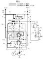
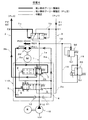
図1は、本実施形態に係る油圧回路100の構成を簡略化して示した説明図である。
この油圧回路100は、第1ポンプ10及び第2ポンプ20を併用してベルト式無段変速機(以下、「CVT」ともいう。)の第1プーリーPu1(第1油圧機器)及び第2プーリーPu2(第2油圧機器)にオイル(油圧)を供給するCVT用油圧回路である。第1ポンプ10はCVTの摩擦伝動に最低限必要とされる圧力(以下、「PL圧」又は「第1油圧」ともいう。)を供給すると共に、第2ポンプ20はCVTの変速比制御に必要とされる圧力(以下、「変速比圧」又は「第2油圧」ともいう。)を第1プーリーPu1又は第2プーリーPu2へ交互に供給する。
FIG. 1 is an explanatory diagram showing a simplified configuration of a
The
本油圧回路100では、プーリー駆動圧が低い方のプーリー(以下、「低圧プーリー」ともいう。)のプーリー駆動圧は、第1ポンプ10によって常にPL圧に維持されると共に、駆動圧が高い方のプーリー(以下、「高圧プーリー」ともいう。)のプーリー駆動圧は、第1ポンプ10によるPL圧に加えて、第2ポンプ20によって変速比圧が付加される。従って、第1プーリー駆動圧P1及び第2プーリー駆動圧P2の何れの駆動圧もPL圧を下回ることはない。
In the
特に、本油圧回路100は油圧ブースト機構110(一点鎖線にて囲まれた部分)を備えている。油圧ブースト機構110は一定条件下、第2ポンプ20の吸込口(低圧側ポート)に通じるラインに中間圧を発生させ、この中間圧によって第2ポンプ20の吸込口(低圧側ポート)を昇圧するように構成されている。第2ポンプ20の吸込口が中間圧によって昇圧されることにより、第2ポンプ20を駆動するモータMの動力が小さい場合であっても瞬時に高圧プーリーに対し十分高い変速比圧を供給することが可能となる。
In particular, the
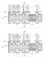
上記油圧回路100の構成として、第1ポンプ10と第1プーリーPu1又は第2プーリーPu2とを接続する第1ライン1と、第2ポンプ20と第1プーリーPu1とを接続する第2ライン2と、第2ポンプ20と第2プーリーPu2とを接続する第3ライン3と、第2ライン2から分岐して第1逆止弁11を介して第1ライン1に接続する第4ライン4と、第3ライン3から分岐して第2逆止弁12を介して第1ライン1に接続する第5ライン5と、第2ライン2から分岐して第2ブーストバルブ40の第1ポートP1に接続する第6ライン6と、第3ライン3から分岐して第1ブーストバルブ30の第1ポートP1に接続する第7ライン7と、第2ライン2から分岐して第1ブーストバルブ30の第6ポートP6に接続する第8ライン8と、第3ライン3から分岐して第2ブーストバルブ40の第6ポートP6に接続する第9ライン9と、第1ライン1から分岐してPLレギュレータバルブ50に接続する第13ライン13と、第13ライン13から分岐してPLソレノイドバルブ60に接続する第14ライン14と、PLソレノイドバルブ60とPLレギュレータバルブ50とを接続する第15ライン15と、第4ライン4から第1ライン1へのオイルの流入を阻止する第1逆止弁11と、第5ライン5から第1ライン1へのオイルの流入を阻止する第2逆止弁12と、エンジンEによって常時駆動される第1ポンプ10と、モータMによって駆動される第2ポンプ20と、第2ポンプ20の差圧P20を一定値に調圧すると共に第2ポンプ20の低圧側ポート(吸込口)に通じるラインに中間圧を発生させる第1ブーストバルブ30及び第2ブーストバルブ40と、第1ポンプ10の吐出圧を所定圧(PL圧)に調圧するPLレギュレータバルブ50と、PLレギュレータバルブ(圧力調整弁)50の調圧基準圧となるパイロット圧を供給するPLソレノイドバルブ(リニアソレノイド)60と、上記第1ライン1を第1プーリーPu1或いは第2プーリーPu2の何れか一方に切り替えるPLシフトバルブ(切替弁)70と、を具備して構成されている。なお、第2ライン2及び第3ライン3は、説明の都合上、太実線によって表されている。以下、各構成について更に詳細に説明する。
As the configuration of the hydraulic circuit 100, the first line 1 that connects the first pump 10 and the first pulley Pu1 or the second pulley Pu2, and the second line 2 that connects the second pump 20 and the first pulley Pu1; A third line 3 connecting the second pump 20 and the second pulley Pu2, a fourth line 4 branched from the second line 2 and connected to the first line 1 via the first check valve 11, A fifth line 5 branched from the third line 3 and connected to the first line 1 via the second check valve 12 and a branch from the second line 2 connected to the first port P1 of the second boost valve 40 A sixth line 6 that branches from the third line 3 and connects to the first port P1 of the first boost valve 30; a sixth line 6 that branches from the second line 2 and the sixth line of the first boost valve 30; 8th line connected to port P6 A ninth line 9 branched from the third line 3 and connected to the sixth port P6 of the second boost valve 40, a thirteenth line 13 branched from the first line 1 and connected to the PL regulator valve 50, The fourteenth line 14 branched from the thirteenth line 13 and connected to the PL solenoid valve 60, the fifteenth line 15 connecting the PL solenoid valve 60 and the PL regulator valve 50, and the fourth line 4 to the first line 1 A first check valve 11 for blocking the inflow of oil, a second check valve 12 for blocking the inflow of oil from the fifth line 5 to the first line 1, and a first pump that is always driven by the engine E 10, the second pump 20 driven by the motor M, and the differential pressure P20 of the second pump 20 are adjusted to a constant value and the low-pressure side port (suction port) of the second pump 20 A first boost valve 30 and a second boost valve 40 that generate an intermediate pressure in a line that communicates, a PL regulator valve 50 that regulates the discharge pressure of the first pump 10 to a predetermined pressure (PL pressure), and a PL regulator valve (pressure adjustment) A PL solenoid valve (linear solenoid) 60 for supplying a pilot pressure as a pressure regulation reference pressure of the valve 50, and a PL shift valve for switching the first line 1 to either the first pulley Pu1 or the second pulley Pu2. Switching valve) 70. The
第1ライン1は、第1ポンプ10から吐出されるオイル(PL圧)を第1プーリーPu1及び第2プーリーPu2に移送するための油路である。第1ライン1は、第1ポンプ10とPLシフトバルブ70とを接続するプーリー1次圧力ライン1aと、PLシフトバルブ70と第1プーリーPu1とを接続する第1プーリー2次圧力ライン1bと、PLシフトバルブ70と第2プーリーPu2とを接続する第2プーリー2次圧力ライン1cとから構成される。
The
第1プーリー2次圧力ライン1bと第2ライン2は、図中の点C1で結合している。従って、第1プーリーPu1が低圧プーリーの場合(すなわち、プーリー1次圧力ライン1aと第1プーリー2次圧力ライン1bとが連通する場合)、第1ポンプ10から吐出されるオイルは、一部が第1プーリーPu1に供給され、残りが第2ライン2を通って第2ポンプ20に供給される。第2ポンプ20に供給されたオイルは、第2ポンプ20によって昇圧された後、第3ライン3を通って第2プーリーPu2に供給される。
The first pulley secondary pressure line 1b and the
一方、第2プーリー2次圧力ライン1cと第3ライン3は、図中の点C2で結合している。従って、第2プーリーPu2が低圧プーリーの場合(すなわち、プーリー1次圧力ライン1aと第2プーリー2次圧力ライン1cとが連通する場合)、第1ポンプ10から吐出されるオイルは、一部が第2プーリーPu2に供給され、残りが第3ライン3を通って第2ポンプ20に供給される。第2ポンプ20に供給されたオイルは、第2ポンプ20によって昇圧された後、第2ライン2を通って第1プーリーPu1に供給される。
On the other hand, the second pulley secondary pressure line 1c and the
第2ライン2は、第1プーリーPu1が高圧プーリーの場合、第2ポンプ20の差圧P20(変速比圧)を第1プーリーPu1に移送するための高圧油路となる。第2ライン2は、第2ポンプ20と第2ブーストバルブ40とを接続する第2ライン2aと、第2ブーストバルブ40と第1プーリーPu1とを接続する第2ライン2bとから構成される。また、上記「第2ポンプ20の差圧P20」とは、第2ポンプ20のポートP21とポートP22とのポート間圧力差を意味し、単に「第2ポンプ差圧P20」ともいわれる。
When the first pulley Pu1 is a high-pressure pulley, the
第2ライン2aのライン圧(つまり、第2ポンプ20のポートP21側の圧力)は、第6ライン6を介して第2ブーストバルブ40に供給されるのと同時に、第8ライン8を介して第1ブーストバルブ30に供給される。
The line pressure of the
第3ライン3は、第2プーリーPu2が高圧プーリーの場合、第2ポンプ差圧P20(変速比圧)を第2プーリーPu2に移送するための高圧油路となる。第3ライン3は、第2ポンプ20と第1ブーストバルブ30とを接続する第3ライン3aと、第1ブーストバルブ30と第2プーリーPu2とを接続する第3ライン3bとから構成される。
When the second pulley Pu2 is a high pressure pulley, the
第3ライン3aのライン圧(つまり、第2ポンプ20のポートP22側の圧力)は、第7ライン7を介して第1ブーストバルブ30に供給されるのと同時に、第9ライン9を介して第2ブーストバルブ40に供給される。
The line pressure of the
第1ブーストバルブ30及び第2ブーストバルブ40は、外部に6つのポートP1〜P6と、内部にプーリー1次圧力ライン1aに連通する油路と、第2ライン2又は第3ライン3に連通する油路とをそれぞれ有している。
The
また、第1ブーストバルブ30及び第2ブーストバルブ40は、図中のAからCにて示されるバルブ位置をそれぞれ有している。従って、詳細については後述するが、第2ポンプ差圧P20が設定圧(スプリング荷重圧)を超える場合、弁体がバルブ位置AからB又はCに移動して、第3ライン3又は第2ライン2、或いはプーリー1次圧力ライン1aを閉じるように構成されている。上記ラインが閉じられることにより、中間圧(PL圧<中間圧<最大プーリー駆動圧)が上記ラインに発生することになる。中間圧は第2ポンプ20の吸込口の圧力(吸込圧)を昇圧させる。これにより、高圧プーリー駆動圧が増大するようになる。
Further, the
また、第2ポンプ差圧P20は、第1ブーストバルブ30の弁体31(図2)並びに第2ブーストバルブ40の弁体41(図2)に対し、第7ライン7及び第8ライン8又は第6ライン6及び第9ライン9を介して互いに逆方向に常時作用している。これにより、第1ブーストバルブ30と第2ブーストバルブ40の各動作が互いに逆になり、第2ポンプ差圧P20の向きが変わる毎に、第1プーリーPu1又は第2プーリーPu2に対し変速比制御に必要な高い油圧が交互に供給されるようになる。
The second pump differential pressure P20 is applied to the
PLレギュレータバルブ50は、第1ポンプ10の吐出圧を元圧及びフィードバック圧として取り込み、フィードバック圧とパイロット圧及びスプリング荷重との力の釣り合いによって、第1ポンプ10の吐出圧をPL圧に調圧する圧力調整弁である。なお、パイロット圧はPLソレノイドバルブ60によって供給される。
The
PLソレノイドバルブ60は、第1ポンプ10の吐出圧を元圧としてリニアソレノイドによって調圧し、その出力値をパイロット圧としてPLレギュレータバルブ50に出力する。
The
PLシフトバルブ70は、内部に2系統の油路(第1プーリー2次圧力ライン1bに通じる油路と、第2プーリー2次圧力ライン1cに通じる油路)を有する。また、弁体はバネによって軸方向左側に付勢され、フィードバック圧として第1プーリー駆動圧P1及び第2プーリー駆動圧P2をそれぞれ取り込む。
The
従って、第2プーリー駆動圧P2と第1プーリー駆動圧P1との差圧がバネによる荷重圧を上回る場合、弁体が軸方向右側に移動し、第1プーリー2次圧力ライン1bに通じる油路が選択される。他方、第2プーリー駆動圧P2と第1プーリー駆動圧P1との差圧がバネによる荷重圧を下回る場合は、弁体が軸方向左側に移動し、第2プーリー2次圧力ライン1cに通じる油路が選択される。 Accordingly, when the differential pressure between the second pulley driving pressure P2 and the first pulley driving pressure P1 exceeds the load pressure by the spring, the valve body moves to the right in the axial direction, and the oil passage leading to the first pulley secondary pressure line 1b. Is selected. On the other hand, when the differential pressure between the second pulley driving pressure P2 and the first pulley driving pressure P1 is lower than the load pressure by the spring, the valve body moves to the left in the axial direction, and the oil that leads to the second pulley secondary pressure line 1c. A road is selected.
第1ポンプ10は、容積型ポンプ、例えば内接ギヤポンプである。第1プーリーPu1及び第2プーリーPu2に対し、CVTの摩擦伝動に最低限必要されるPL圧を供給する。
The
第2ポンプ20は、一方のプーリーから他方のプーリーへ交互に変速比制御に必要なオイルを移動させる往復式ポンプである。従って、オイルが第1プーリーPu1へ供給される場合、ポートP21は吐出口となり、ポートP22は吸込口となる。他方、オイルが第2プーリーPu2へ供給される場合、ポートP22は吐出口となり、ポートP21は吸込口となる。また、第2ポンプ20のオイル流量(第2ポンプ流量)Q20は高圧プーリーのオイル流量に常に等しくなる。
The
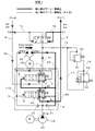
プーリー制御装置PCUは、実プーリー位置PISAを目標プーリー位置PISTに追従する(近付ける)ように第2ポンプ20のモータMの出力(動力)を制御する。これについては、図4を参照しながら後述する。
The pulley control unit PCU controls the output (power) of the motor M of the
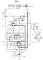
図2は、本実施形態に係る第1ブーストバルブ30及び第2ブーストバルブ40を示す要部断面説明図である。なお、第1ブーストバルブ30と第2ブーストバルブ40の各内部構造は同一であるため、第2ブーストバルブ40についての説明は省略することにする。また、説明の都合上、各ポートに接続される油路(プーリー1次圧力ライン1a、第2ライン2a,2b、第3ライン3a,3b、第6ライン6、第7ライン7、第8ライン8、第9ライン9)についても併せて図示されている。
FIG. 2 is an explanatory cross-sectional view of a main part showing the
また、第1ブーストバルブ30及び第2ブーストバルブ40の各内部構造において、類似構成については、例えば弁体31,41のように、一の位に同一番号を付し、十の位に各バルブ番号を付してお互いを区別することにする。
Moreover, in each internal structure of the
第1ブーストバルブ30は、弁体31とボディ32とスプリング33とから構成されている。弁体31には軸方向左側から順に、第5ポートP5を絞る又は閉じるための第1周状凸部31aと、第4ポートP4と第5ポートP5とを連通する第1周状凹部31bと、第3ポートP3を絞る又は閉じるための第2周状凸部31cと、第2ポートP2と第3ポートP3を連通する第2周状凹部31dと、がそれぞれ形成されている。
The
ボディ32には軸方向右側から順に、第7ライン7を介して第2ポンプ20のポートP22の圧力を導入するための第1ポートP1と、プーリー1次圧力ライン1aを介してPLシフトバルブ70へ油圧(PL圧)を供給するための第2ポートP2と、プーリー1次圧力ライン1aを介して第1ポンプ10の吐出圧(PL圧)を導入するための第3ポートP3と、第3ライン3aを介して第2ポンプ20のポートP22の圧力を導入する第4ポートP4と、第3ライン3bを介して第2プーリーPu2へ或いは第2プーリーPu2から油圧を授受するための第5ポートP5と、第8ライン8を介して第2ポンプ20のポートP21の圧力を導入するための第6ポートP6とがそれぞれ形成されている。さらに弁体31が突き当たる左エンド部32aと、スプリング33が突き当たる右エンド部32bとがそれぞれ形成されている。
In order from the axial right side to the
弁体31において、第2ポンプ20のポートP22の圧力が作用する軸方向の投影面積(ピストン作用面積)S1と、第2ポンプ20のポートP21の圧力が作用する軸方向の投影面積(ピストン作用面積)S2は等しくなっている。これは第2ブーストバルブ40の弁体41においても同様である。
In the
特に、第2ポンプ20のポートP21の圧力は、第1ブーストバルブ30では第6ポートP6に作用しているのに対し、第2ブーストバルブ40では第1ポートP1に作用している。同様に、第2ポンプ20のポートP22の圧力は、第1ブーストバルブ30では第1ポートP1に作用しているのに対し、第2ブーストバルブ40では第6ポートP6に作用している。つまり、第2ポンプ差圧P20(ポートP21とポートP22とのポート間圧力差)は、第1ブーストバルブ30の弁体31と第2ブーストバルブ40の弁体41に対し、互いに逆方向に作用している。
In particular, the pressure at the port P21 of the
第2ポンプ差圧P20が、第1ブーストバルブ30と第2ブーストバルブ40において互いに逆方向に作用することにより、各弁体31,41の動作が互いに逆となる。
When the second pump differential pressure P20 acts in the opposite directions in the
なお、詳細については後述するが、第2ポンプ差圧P20(=ポートP21とポートP22とのポート間圧力差)がスプリング荷重圧PS(=スプリング33の荷重÷ピストン作用面積)を上回る場合、弁体31が軸方向右側に移動して、第3ライン3aに中間圧を発生させ、或いは第1ポンプ吐出圧P10を昇圧させる。これにより第2ポンプ20のポートP22の圧力を昇圧させると共に、第2ポンプ差圧P20を一定値(=スプリング荷重圧PS)に調圧する。
Although details will be described later, when the second pump differential pressure P20 (= pressure difference between the ports P21 and P22) exceeds the spring load pressure PS (= load of the
また、第2ブーストバルブ40も同様に、第2ポンプ差圧P20が設定圧(スプリング荷重圧PS)を上回る場合、第2ライン2aに中間圧を発生させ、或いは第1ポンプ吐出圧P10を昇圧させる。これにより第2ポンプ20のポートP21の圧力を昇圧させると共に、第2ポンプ差圧P20を一定値(=スプリング荷重圧PS)に調圧する。
Similarly, when the second pump differential pressure P20 exceeds the set pressure (spring load pressure PS), the
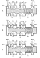
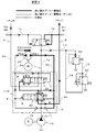
図3は、本実施形態に係る第1ブーストバルブ30のバルブ位置を示す説明図である。なお、AからCによって示される各バルブ位置は図1中に示される各バルブ位置にそれぞれ対応している。
FIG. 3 is an explanatory diagram showing the valve position of the
バルブ位置Aでは、設定圧(スプリング荷重圧PS)が第2ポンプ差圧P20を上回っており、弁体31がスプリング33に押されて左エンド部32aに突き当たっている状態である。この場合、第5ポートP5及び第3ポートP3がともに開いた状態である。従って、第3ライン3及び第1ライン1はともに開いた状態である。
At the valve position A, the set pressure (spring load pressure PS) exceeds the second pump differential pressure P20, and the
バルブ位置Bは、第5ポートP5が閉じられた直後の状態である。バルブ位置Aにおいて、第2ポンプ差圧P20が設定圧(スプリング荷重圧PS)を上回るとき、弁体31は軸方向右側に移動し始める。弁体31が軸方向右側に移動することにより、第5ポートP5が閉じられるようになる。第5ポートP5が閉じられることにより、第2ポンプ20のポートP22に通じるライン(例えば第3ライン3a)のライン圧が上昇し中間圧を発生させる。中間圧が発生することにより、第2ポンプ20のポートP22の圧力(吸込圧)が昇圧する。これにより、第2ポンプ20のポートP21の圧力(吐出圧)が増大し、高圧プーリーに対し高い駆動圧を供給することが可能となる。なお、第2ポンプ差圧P20が設定圧(スプリング荷重圧PS)に等しくなるところで、弁体31は静止する。
The valve position B is a state immediately after the fifth port P5 is closed. When the second pump differential pressure P20 exceeds the set pressure (spring load pressure PS) at the valve position A, the
バルブ位置Cは、第3ポートP3が閉じられた直後の状態である。バルブ位置Bにおいて、第5ポートP5が閉じられてもなお、第2ポンプ差圧P20が設定圧(スプリング荷重圧PS)より大きい場合は、弁体31はさらに軸方向右側に移動する。そして、第3ポートP3を閉じるようになる。第3ポートP3が閉じられることにより、第1ポンプ10の吐出圧P10が昇圧するようになる。昇圧した第1ポンプ10の吐出圧P10は、第5ライン5(図1)を介して、第2ポンプ20のポートP22に通じるライン(例えば第3ライン3a)を昇圧させる。これにより、第2ポンプ20のポートP22(吸込口)の圧力が昇圧する。これにより、第2ポンプ20のポートP21の圧力(吐出圧)が増大し、高圧プーリーに対し高い駆動圧を供給することが可能となる。なお、第2ポンプ差圧P20が設定圧(スプリング荷重圧PS)に等しくなるところで、弁体31は静止する。
The valve position C is a state immediately after the third port P3 is closed. Even when the fifth port P5 is closed at the valve position B, if the second pump differential pressure P20 is higher than the set pressure (spring load pressure PS), the
以上の通り、第2ポンプ差圧P20が上昇すると、弁体31は軸方向右側に移動して、先ず第3ライン3の開閉に係る第5ポートP5が閉じられるようになる。そして、第5ポートP5が閉じられてもなお、第2ポンプ差圧P20が設定圧(スプリング荷重圧PS)より大きい場合は、プーリー1次圧力ライン1aの開閉に係る第3ポートP3が閉じられるようになる。
As described above, when the second pump differential pressure P20 rises, the
このように、第1ブーストバルブ30は、第2ポンプ差圧P20に応じて、バルブ位置AからBへ1段階動作して、或いはバルブ位置AからCへ2段階動作して、第2ポンプ20の吐出圧を増大させる(つまり、高圧プーリーの駆動圧を増大させる)と共に第2ポンプ差圧P20を設定圧(スプリング荷重圧PS)に等しくなるように調圧する。
As described above, the
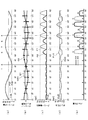
図4は、プーリー制御装置PCUが、位置指令として目標プーリー位置PIST(図4(a)の実線部)を受信したときに、実プーリー位置PISA(図4(a)の点線部)を目標プーリー位置PISTに追従する(近付ける)ように第2ポンプ20のモータMを制御した際の各データの時系列変化を示している。なお、図4(a)上に記載されている1から6の各番号は、後述される代表的な動作状態を示している。
FIG. 4 shows that when the pulley control unit PCU receives the target pulley position PIST (solid line part of FIG. 4A) as a position command, the actual pulley position PISA (dotted line part of FIG. 4A) is changed to the target pulley. A time-series change of each data when the motor M of the
データは、上から順に、プーリー位置PIST,PISA、プーリー流量Q1,Q2及び第2ポンプ流量Q20、プーリー駆動圧P1,P2、ポンプ圧力P10,P20、第1及び第2ブーストバルブ30,40の各バルブ位置に関する時刻2Tから時刻18Tにおける時系列変化をそれぞれ示している。以下、各データについて説明する。
The data are, in order from the top, pulley position PIST, PISA, pulley flow rate Q1, Q2, second pump flow rate Q20, pulley drive pressure P1, P2, pump pressure P10, P20, first and
図4(a)では、実プーリー位置PISAとして、第1プーリーPu1の可動プーリーの実位置が示されている。この実プーリー位置PISAは、プーリー変速比に係るプーリー溝幅に相当する。第1プーリーPu1の可動プーリーは、原点(基準点)から2.5Lの位置を中心として1.5Lの振幅で、周期8Tの単振動をしている。 In FIG. 4A, the actual position of the movable pulley of the first pulley Pu1 is shown as the actual pulley position PISA. The actual pulley position PISA corresponds to the pulley groove width related to the pulley gear ratio. The movable pulley of the first pulley Pu1 makes a single vibration with a period of 8T with an amplitude of 1.5L centering on a position 2.5L from the origin (reference point).
図4(b)は、第1プーリーPu1が図4(a)に示される単振動しているときの、第1プーリー流量Q1(実線部)、第2プーリー流量Q2(太線部)及び第2ポンプ流量Q20(太点線部)をそれぞれ示している。なお、流量の符号は、オイルがプーリーへ流入している場合を正とし、オイルがプーリーから流出している場合を負としている。 FIG. 4B shows the first pulley flow rate Q1 (solid line portion), the second pulley flow rate Q2 (thick line portion), and the second when the first pulley Pu1 is simply oscillating as shown in FIG. The pump flow rate Q20 (thick dotted line portion) is shown. The sign of the flow rate is positive when oil flows into the pulley and negative when oil flows out of the pulley.
図4(a)及び図4(b)に示されるように、オイルが第1プーリーPu1から流出している間は、実プーリー位置PISAは、プーリー溝幅が拡大する方向に増加している。他方、オイルが第1プーリーPu1へ流入している間は、実プーリー位置PISAは、プーリー溝幅が狭くなる方向に減少している。 As shown in FIGS. 4A and 4B, the actual pulley position PISA increases in the direction in which the pulley groove width increases while the oil flows out from the first pulley Pu1. On the other hand, while the oil flows into the first pulley Pu1, the actual pulley position PISA decreases in the direction in which the pulley groove width becomes narrower.
また、図4(b)に示されるように、第2ポンプ流量Q20の絶対値は、高圧プーリーの流量の絶対値に常に等しくなる。例えば、図4(c)から時刻2Tから時刻3Tにおいては、第2ポンプ流量Q20の絶対値は第2プーリー流量Q2の絶対値に等しくなっている。他方、時刻3Tから時刻4Tにおいては、第2ポンプ流量Q20の絶対値は第1プーリー流量Q1の絶対値に等しくなっている。
Further, as shown in FIG. 4B, the absolute value of the second pump flow rate Q20 is always equal to the absolute value of the flow rate of the high-pressure pulley. For example, from FIG. 4C, from
また、図4(c)及び図4(d)に示されるように、第2ポンプ差圧P20の向き(吐出方向)は一定周期Tで交互に切り替わっている。これにより、プーリー駆動圧の大小関係が周期Tで交互に切り替わっている。なお、第2ポンプ差圧P20の符号について、第1プーリー駆動圧P1が昇圧される向きを正とし、第2プーリー駆動圧P2が昇圧される向きを負としている。 Also, as shown in FIGS. 4C and 4D, the direction (discharge direction) of the second pump differential pressure P20 is alternately switched at a constant period T. As a result, the magnitude relationship of the pulley driving pressure is alternately switched at the period T. Regarding the sign of the second pump differential pressure P20, the direction in which the first pulley drive pressure P1 is increased is positive, and the direction in which the second pulley drive pressure P2 is increased is negative.
また、図4(d)に示されるように、プーリー制御装置PCUは、時刻10Tにおいて第2ポンプ差圧P20の最大値(モータMの最大出力(動力))を引き上げている。すなわち、時刻10T以前において第2ポンプ差圧P20の最大値はa[bar]未満であるのに対し、時刻10T以降では第2ポンプ差圧P20の最大値はa[bar]としている。
Further, as shown in FIG. 4D, the pulley control unit PCU increases the maximum value of the second pump differential pressure P20 (maximum output (power) of the motor M) at
また、図4(d)及び図4(e)に示されるように、第1ブーストバルブ30及び第2ブーストバルブ40は、第2ポンプ差圧P20の最大値が設定圧(スプリング荷重圧PS)より小さい場合(時刻10T以前)は動作しないように構成されている。
Further, as shown in FIGS. 4D and 4E, the
そして、第2ポンプ差圧P20が設定圧(スプリング荷重圧PS)を上回るときに、第1ブーストバルブ30及び第2ブーストバルブ40はバルブ位置AからBへ1段階動作し、或いはバルブ位置AからCへ2段階動作して第1プーリー駆動圧P1又は第2プーリー駆動圧P2を増大させている。また、同時に第2ポンプ20の差圧P20を設定圧(スプリング荷重圧PS)に等しくなるように調圧している。
When the second pump differential pressure P20 exceeds the set pressure (spring load pressure PS), the
このように、第2ポンプ差圧P20の最大値、すなわちモータMの最大出力を引き上げることにより、第1ブーストバルブ30及び第2ブーストバルブ40がバルブ位置AからBへ1段階動作し、或いはバルブ位置AからCへ2段階動作して第1プーリー駆動圧P1又は第2プーリー駆動圧P2を交互に増大させるようになる。
Thus, by raising the maximum value of the second pump differential pressure P20, that is, the maximum output of the motor M, the
なお、図12は、本発明に係る油圧ブースト機構110を備えていない従来の油圧回路500(図11)において、本油圧回路100と同様にプーリー制御装置PCUに、位置指令として上記目標プーリー位置PISTを送信した際の各データの時系列変化を示すものである。
12 shows a conventional hydraulic circuit 500 (FIG. 11) that does not include the
例えば、図12(d)の状態3及び状態4において、4a[bar]の第1プーリー駆動圧P1を確保するために、従来の油圧回路500では第2ポンプ差圧P20の最大値を3a[bar]に設定する必要がある。それに対し、本油圧回路100では同一状態において第2ポンプ差圧P20の最大値をa[bar]に設定すれば足りることになる。
For example, in the
このように、本油圧回路100では、第2ポンプ20の吸込口(低圧側ポート)に連通するラインの途中に所定条件下で中間圧を発生させる油圧ブースト機構110(第1ブーストバルブ30及び第2ブーストバルブ40)が設けられている。そのため、第2ポンプ20を駆動するモータMの動力が小さい場合であっても、高圧プーリーに対し高いプーリー駆動圧を供給することが可能となる。以下、図5から図10を参照しながら中間圧が発生する仕組みについて説明する。
As described above, in the
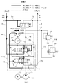
図5は、図4の状態1における油圧回路100の動作を示す説明図である。状態1では、高圧プーリーは第1プーリーPu1であり、低圧プーリーは第2プーリーPu2である。また、第1プーリーPu1はオイルが流入し、第2プーリーPu2はオイルが流出している状態である。
FIG. 5 is an explanatory diagram showing the operation of the
従って、第2ポンプ差圧P20は、第1ブーストバルブ30では第6ポートP6から第1ポートP1に向かって作用している。一方、第2ブーストバルブ40では第1ポートP1から第6ポートP6に向かって作用している。
Accordingly, the second pump differential pressure P20 acts from the sixth port P6 toward the first port P1 in the
しかし、図4(d)に示されるように、第2ポンプ差圧P20は設定圧(スプリング荷重圧PS)より小さいため、何れのブーストバルブ30,40も動作せずにバルブ位置Aで静止している。
However, as shown in FIG. 4 (d), the second pump differential pressure P20 is smaller than the set pressure (spring load pressure PS), so that none of the
図6は、図4の状態2における油圧回路100の動作を示す説明図である。状態2では、高圧プーリーは第2プーリーPu2であり、低圧プーリーは第1プーリーPu1である。また、第1プーリーPu1はオイルが流出し、第2プーリーPu2はオイルが流入している状態である。
FIG. 6 is an explanatory diagram showing the operation of the
従って、第2ポンプ差圧P20は、第1ブーストバルブ30では第1ポートP1から第6ポートP6に向かって作用している。一方、第2ブーストバルブ40では第6ポートP6から第1ポートP1に向かって作用している。
Accordingly, the second pump differential pressure P20 acts from the first port P1 toward the sixth port P6 in the
しかし、図4(d)に示されるように、第2ポンプ差圧P20は設定圧(スプリング荷重圧PS)より小さいため、何れのブーストバルブ30,40も動作せずにバルブ位置Aで静止している。
However, as shown in FIG. 4 (d), the second pump differential pressure P20 is smaller than the set pressure (spring load pressure PS), so that none of the
図7は、図4の状態3における油圧回路100の動作を示す説明図である。状態3では、高圧プーリーは第1プーリーPu1であり、低圧プーリーは第2プーリーPu2である。また、第1プーリーPu1はオイルが流出し、第2プーリーPu2はオイルが流入している状態である。
FIG. 7 is an explanatory diagram showing the operation of the
従って、第2ポンプ差圧P20は、第1ブーストバルブ30では第6ポートP6から第1ポートP1に向かって作用している。一方、第2ブーストバルブ40では第1ポートP1から第6ポートP6に向かって作用している。
Accordingly, the second pump differential pressure P20 acts from the sixth port P6 toward the first port P1 in the
状態3では第2ポンプ差圧P20の最大値はa[bar]に設定されている。従って、第2ポンプ差圧P20が設定圧(スプリング荷重圧PS)を上回るときに、第1ブーストバルブ30の弁体31がバルブ位置AからBへ1段階動作し、第5ポートP5を閉じるようになる。第5ポートP5が閉じられ、オイルの流れが阻まれることにより、第3ライン3a、第5ライン5、第7ライン7及び第9ライン9において中間圧(点線部)が発生する。
In
中間圧は、第2ポンプ20のポートP22側、すなわち第2ポンプ20の低圧側の圧力を増大させる。その結果、図4(c)に示されるように、第1プーリーPu1には、PL圧及び第2ポンプ差圧P20に加えて中間圧も加わるため、第1プーリー駆動圧P1が、中間圧が発生しない場合に比べ増大するようになる。
The intermediate pressure increases the pressure on the port P22 side of the
このように、第1プーリーPu1が高圧プーリーであり且つ第2プーリーPu2が低圧プーリーであるとき、オイルが第1プーリーPu1(高圧プーリー)から流出している場合、第2ポンプ差圧P20が設定圧(スプリング荷重圧PS)を上回るときに、第1ブーストバルブ30はバルブ位置AからBへ1段階動作して、第2ポンプ差圧P20を設定圧(スプリング荷重圧PS)に等しくする。それと同時に、第1ブーストバルブ30は第2ポンプ20の吸込口(P22)の圧力を中間圧によって増大させる。これにより、図4(d)に示されるように第1プーリー駆動圧P1が増大するようになる。
As described above, when the first pulley Pu1 is a high pressure pulley and the second pulley Pu2 is a low pressure pulley, when the oil flows out from the first pulley Pu1 (high pressure pulley), the second pump differential pressure P20 is set. When the pressure (spring load pressure PS) is exceeded, the
図8は、図4の状態4における油圧回路100の動作を示す説明図である。状態4では、状態3と同様に、高圧プーリーは第1プーリーPu1であり、低圧プーリーは第2プーリーPu2である。しかし、オイルの流れる方向については、状態3と異なり、第1プーリーPu1はオイルが流入し、第2プーリーPu2はオイルが流出している。
FIG. 8 is an explanatory diagram showing the operation of the
従って、状態3と同様に、第2ポンプ差圧P20が設定圧(スプリング荷重圧PS)を上回るときに、第1ブーストバルブ30の弁体31が軸方向右側に移動し始める。これにより弁体31が第5ポートP5を閉じるようになる。
Accordingly, similarly to the
しかし、状態4では、状態3と異なり第2ポンプ差圧P20の方向と、第1プーリー流量Q1の流れる方向が一致している。そのため、第1ブーストバルブ30の第5ポートP5が閉じて閉塞状態となった第3ライン3aから第2ポンプ20によりオイルが吸い出されることで中間圧は減少し,第1ブーストバルブ30の第1ポートP1の圧力も減少する。これにより、第1ブーストバルブ30はバルブ位置AからCへ2段階動作して、第5ポートP5に加えて第3ポートP3も閉じるようになる。
However, in the
第3ポートP3が閉じられることにより、プーリー1次圧力ライン1aが閉じられる。プーリー1次圧力ライン1aが閉じられることにより、第1ポンプ10から吐出されるオイルの流れが阻まれる。その結果、図4(d)に示されるように、第1ポンプ吐出圧P10が昇圧(ブースト)されるようになる。昇圧された第1ポンプ吐出圧P10は、第5ライン5及び第3ライン3aを介して第2ポンプ20のポートP22(吸込口)の圧力を増大させる。これにより、図4(d)に示されるように第1プーリー駆動圧P1が増大するようになる。なお、第4ライン4のライン圧は第1ポンプ吐出圧P10より高いため、第1逆止弁11は閉状態にある。従って、第1ポンプ10の昇圧により、第2ポンプ20のポートP21側にオイルが流入することはない。
The pulley
このように、第1プーリーPu1が高圧プーリーであり且つ第2プーリーPu2が低圧プーリーであるとき、オイルが第1プーリーPu1(高圧プーリー)に流入している場合、第2ポンプ差圧P20が設定圧(スプリング荷重圧PS)を上回るときに、第1ブーストバルブ30はバルブ位置AからCへ2段階動作して、第2ポンプ差圧P20を設定圧(スプリング荷重圧PS)に等しくすると共に、第1ポンプ吐出圧P10を昇圧させ、これにより、第1プーリー駆動圧P1を増大させる。
Thus, when the first pulley Pu1 is a high pressure pulley and the second pulley Pu2 is a low pressure pulley, when the oil flows into the first pulley Pu1 (high pressure pulley), the second pump differential pressure P20 is set. When the pressure (spring load pressure PS) is exceeded, the
図9は、図4の状態5における油圧回路100の動作を示す説明図である。状態5は、状態3における第1プーリーPu1と第2プーリーPu2の大小関係、並びに各オイルの流れる方向を反転させたものに相当する。
FIG. 9 is an explanatory diagram showing the operation of the
従って、第2ポンプ差圧P20は、第1ブーストバルブ30では第1ポートP1から第6ポートP6に向かって作用している。一方、第2ブーストバルブ40では第6ポートP6から第1ポートP1に向かって作用している。
Accordingly, the second pump differential pressure P20 acts from the first port P1 toward the sixth port P6 in the
状態5では第2ポンプ差圧P20の最大値はa[bar]に設定されている。従って、第2ポンプ差圧P20が設定圧(スプリング荷重圧PS)を上回るときに、第2ブーストバルブ40の弁体41がバルブ位置AからBへ1段階動作し、第5ポートP5を閉じるようになる。第5ポートP5が閉じられ、オイルの流れが阻まれることにより、第2ライン2a、第4ライン4、第6ライン6及び第8ライン8において中間圧(点線部)が発生する。
In the
中間圧は、第2ポンプ20のポートP21側、すなわち第2ポンプ20の低圧側の圧力を増大させる。その結果、図4(c)に示されるように、第2プーリーPu2には、PL圧及び第2ポンプ差圧P20に加えて中間圧も加わるため、第2プーリー駆動圧P2が、中間圧が発生しない場合に比べ増大するようになる。
The intermediate pressure increases the pressure on the port P21 side of the
このように、第2プーリーPu2が高圧プーリーであり且つ第1プーリーPu1が低圧プーリーであるとき、オイルが第2プーリーPu2(高圧プーリー)から流出している場合、第2ポンプ差圧P20が設定圧(スプリング荷重圧PS)を上回るときに、第2ブーストバルブ40はバルブ位置AからBへ1段階動作して、第2ポンプ差圧P20を設定圧(スプリング荷重圧PS)に等しくする。それと同時に、第2ブーストバルブ40は第2ポンプ20の吸込口(P21)の圧力を中間圧によって増大させる。これにより、図4(d)に示されるように第2プーリー駆動圧P2が増大するようになる。
Thus, when the second pulley Pu2 is a high pressure pulley and the first pulley Pu1 is a low pressure pulley, when the oil flows out from the second pulley Pu2 (high pressure pulley), the second pump differential pressure P20 is set. When the pressure exceeds the pressure (spring load pressure PS), the
図10は、図4の状態6における油圧回路100の動作を示す説明図である。状態6では、状態5と同様に、高圧プーリーは第2プーリーPu2であり、低圧プーリーは第1プーリーPu1である。しかし、オイルの流れる方向については、状態5と異なり、第1プーリーPu1はオイルが流出し、第2プーリーPu2はオイルが流入している。
FIG. 10 is an explanatory diagram showing the operation of the
従って、状態5と同様に、第2ポンプ差圧P20が設定圧(スプリング荷重圧PS)を上回るときに、第2ブーストバルブ40の弁体41が軸方向右側に移動し始める。これにより弁体41が第5ポートP5を閉じるようになる。
Therefore, similarly to the
しかし、状態6では、状態5と異なり第2ポンプ差圧P20の方向と、第2プーリー流量Q2の流れる方向が一致している。そのため、第2ブーストバルブ40の第5ポートP5が閉じて閉塞状態となった第2ライン2aから第2ポンプ20によりオイルが吸いだされることで中間圧は減少し,第2ブーストバルブ40の第1ポートP1の圧力も減少する。これにより、第2ブーストバルブ40はバルブ位置AからCへ2段階動作して、第5ポートP5に加えて第3ポートP3も閉じるようになる。
However, in the
第3ポートP3が閉じられることにより、プーリー1次圧力ライン1aが閉じられる。プーリー1次圧力ライン1aが閉じられることにより、第1ポンプ10から吐出されるオイルの流れが阻まれる。その結果、図4(d)に示されるように、第1ポンプ吐出圧P10が昇圧されるようになる。昇圧された第1ポンプ吐出圧P10は、第4ライン4及び第2ライン2aを介して第2ポンプ20のポートP21(吸込口)の圧力を増大させる。これにより、図4(d)に示されるように第2プーリー駆動圧P2が増大するようになる。なお、第5ライン5のライン圧は第1ポンプ吐出圧P10より高いため、第2逆止弁12は閉状態にある。従って、第1ポンプ10の昇圧により、第2ポンプ20のポートP22側にオイルが流入することはない。
The pulley
このように、第2プーリーPu2が高圧プーリーであり且つ第1プーリーPu1が低圧プーリーであるとき、オイルが第2プーリーPu2(高圧プーリー)に流入している場合、第2ポンプ差圧P20が設定圧(スプリング荷重圧PS)を上回るときに、第2ブーストバルブ40はバルブ位置AからCへ2段階動作して、第2ポンプ差圧P20を設定圧(スプリング荷重圧PS)に等しくすると共に、第1ポンプ吐出圧P10を昇圧させ、これにより、第2プーリー駆動圧P2を増大させる。
Thus, when the second pulley Pu2 is a high pressure pulley and the first pulley Pu1 is a low pressure pulley, when the oil flows into the second pulley Pu2 (high pressure pulley), the second pump differential pressure P20 is set. When the pressure (spring load pressure PS) is exceeded, the
以上の通り、本油圧回路100では、第2ポンプ20の吸込口に連通する第2及び第3ライン2,3並びに第1ポンプ10の吐出口に連通する第1ライン1の途中に、第2ポンプ差圧P20の向き・大きさに応じて別個に動作する第1ブーストバルブ30及び第2ブーストバルブ40が設けられている。第1ブーストバルブ30又は第2ブーストバルブ40は、第2ポンプ差圧P20が設定圧(スプリング荷重圧PS)を上回るときに、バルブ位置AからBへ1段階動作し、或いはバルブ位置AからCへ2段階動作するように構成されている。第1ブーストバルブ30又は第2ブーストバルブ40が1段階動作する場合、第3ライン3又は第2ライン2が閉じられ、オイルの流れが阻まれることにより第3ライン3又は第2ライン2に中間圧が発生する。中間圧は第2ポンプ20の低圧側の圧力(吸込圧)を昇圧させる。これにより、高圧プーリー駆動圧が増大するようになる。
As described above, in the
他方、第1ブーストバルブ30又は第2ブーストバルブ40が2段階動作する場合、プーリー1次圧力ライン1aが閉じられ、第1ポンプ10から吐出されるオイルの流れが阻まれる。これにより第1ポンプ吐出圧P10が昇圧される。昇圧された第1ポンプ吐出圧P10(中間圧)は、第4ライン4又は第5ライン5を介して第2ポンプ20の低圧側の圧力(吸込圧)を昇圧させる。これにより、高圧プーリー駆動圧が増大するようになる。
On the other hand, when the
従って、本油圧回路100によれば、第2ポンプ20を駆動するモータMの動力が小さい場合であっても、第1プーリーPu1又は第2プーリーPu2に対し高いプーリー駆動圧を素早く供給することが可能となる。これにより、第2ポンプ20を駆動するモータMの動力が小さい場合であってもキックダウン・急停車等の素早い変速比制御が可能となる。
Therefore, according to the
また、本油圧回路100では、第2ポンプ差圧P20の最大値、すなわちモータMの最大出力を引き上げることにより、自動的に高圧側のプーリー駆動圧が増大するようになる。そのため、ソレノイド等の電磁弁が不要となる。これは油圧回路の小型化、コストダウン等に寄与することになる。
Further, in the
一般に、第2ポンプ20を駆動するモータMの出力は、「第2ポンプ差圧P20」と「第2ポンプ流量Q20」との積に等しくなる。本油圧回路100では、第1ブーストバルブ30及び第2ブーストバルブ40が動作する際、第2ポンプ差圧P20は上記バルブ30,40によって一定値に調圧される。従って、上記図4(a)に示されるプーリー位置制御においては、「第2ポンプ流量Q20」を制御変数とすれば足りることになる。つまり、本油圧回路100では、第2ポンプ流量Q20を用いたプーリー位置制御が常に可能となる。
In general, the output of the motor M that drives the
1 第1ライン
1a プーリー1次圧力ライン
1b 第1プーリー2次圧力ライン
1c 第2プーリー2次圧力ライン
2、2a、2b 第2ライン
3、3a、3b 第3ライン
4 第4ライン
5 第5ライン
6 第6ライン
7 第7ライン
8 第8ライン
9 第9ライン
10 第1ポンプ
11 第1逆止弁
12 第2逆止弁
13 第13ライン
14 第14ライン
15 第15ライン
20 第2ポンプ
30 第1ブーストバルブ(第1バルブ)
40 第2ブーストバルブ(第2バルブ)
50 PLレギュレータバルブ(圧力調整弁)(第3バルブ)
60 PLソレノイドバルブ(リニアソレノイド)
70 PLシフトバルブ(切替弁)
100 油圧回路
110 油圧ブースト機構
1
40 Second boost valve (second valve)
50 PL regulator valve (pressure regulating valve) (third valve)
60 PL solenoid valve (linear solenoid)
70 PL shift valve (switching valve)
100
Claims (8)
前記第2ポンプの差圧を取り込んで、該差圧が設定圧を超える場合に前記第2ライン又は前記第3ラインのうちライン圧の低い方のラインを閉じる、或いは前記第1ラインを閉じるように構成された油圧ブースト機構を備えることを特徴とする油圧機器用油圧回路。 First and second hydraulic devices that operate as a pair, a first pump that constantly supplies the first hydraulic pressure that is at least necessary to drive the first and second hydraulic devices, and the first hydraulic pressure as a source pressure A second pump for alternately supplying a second hydraulic pressure for controlling a gear ratio to a hydraulic device having a higher driving pressure of the first or second hydraulic device, the first pump, and the first or second A first line that selectively connects a hydraulic device, a second line that connects the second pump and the first hydraulic device, and a third line that connects the second pump and the second hydraulic device. A hydraulic circuit comprising:
When the differential pressure of the second pump is taken in and the differential pressure exceeds a set pressure, the lower line of the second line or the third line is closed, or the first line is closed. A hydraulic circuit for hydraulic equipment, comprising a hydraulic boost mechanism configured as described above.
前記第1ラインと前記第2ラインとをそれぞれ連通させる2系統の内部油路を有する第2バルブとを備え、
前記第1バルブ及び前記第2バルブは、前記第2ポンプの差圧が互いに逆方向に作用するように構成されていることを特徴とする請求項1に記載の油圧機器用油圧回路。 The hydraulic boost mechanism includes a first valve having two internal oil passages that respectively connect the first line and the third line;
A second valve having two internal oil passages for communicating the first line and the second line respectively;
2. The hydraulic circuit for hydraulic equipment according to claim 1, wherein the first valve and the second valve are configured such that a differential pressure of the second pump acts in a direction opposite to each other.
前記第2ラインのライン圧及び前記第3ラインのライン圧が前記弁体の両軸端にそれぞれ作用することを特徴とする請求項2に記載の油圧機器用油圧回路。 The first valve and the second valve are configured by a valve body having irregularities formed on an outer peripheral surface, a body on which the valve body slides, and a spring that biases the valve body,
The hydraulic circuit for hydraulic equipment according to claim 2, wherein the line pressure of the second line and the line pressure of the third line act on both shaft ends of the valve body, respectively.
前記第3バルブに対し前記第1油圧に係るパイロット圧を供給するリニアソレノイドと、を備え、
前記リニアソレノイドの元圧は前記第1ポンプの吐出圧であることを特徴とする請求項1から5の何れかに記載の油圧機器用油圧回路。 A third valve that regulates the discharge pressure of the first pump to the first hydraulic pressure by balancing the force of the feedback pressure and the pilot pressure;
A linear solenoid that supplies a pilot pressure related to the first hydraulic pressure to the third valve;
6. The hydraulic circuit for hydraulic equipment according to claim 1, wherein the original pressure of the linear solenoid is a discharge pressure of the first pump.
Priority Applications (1)
| Application Number | Priority Date | Filing Date | Title |
|---|---|---|---|
| JP2016082124A JP2017190851A (en) | 2016-04-15 | 2016-04-15 | Hydraulic circuit for hydraulic equipment |
Applications Claiming Priority (1)
| Application Number | Priority Date | Filing Date | Title |
|---|---|---|---|
| JP2016082124A JP2017190851A (en) | 2016-04-15 | 2016-04-15 | Hydraulic circuit for hydraulic equipment |
Publications (1)
| Publication Number | Publication Date |
|---|---|
| JP2017190851A true JP2017190851A (en) | 2017-10-19 |
Family
ID=60084694
Family Applications (1)
| Application Number | Title | Priority Date | Filing Date |
|---|---|---|---|
| JP2016082124A Pending JP2017190851A (en) | 2016-04-15 | 2016-04-15 | Hydraulic circuit for hydraulic equipment |
Country Status (1)
| Country | Link |
|---|---|
| JP (1) | JP2017190851A (en) |
Cited By (1)
| Publication number | Priority date | Publication date | Assignee | Title |
|---|---|---|---|---|
| WO2019131463A1 (en) * | 2017-12-28 | 2019-07-04 | 日産自動車株式会社 | Control method for power transmission device, and control device for power transmission device |
-
2016
- 2016-04-15 JP JP2016082124A patent/JP2017190851A/en active Pending
Cited By (2)
| Publication number | Priority date | Publication date | Assignee | Title |
|---|---|---|---|---|
| WO2019131463A1 (en) * | 2017-12-28 | 2019-07-04 | 日産自動車株式会社 | Control method for power transmission device, and control device for power transmission device |
| CN111542711A (en) * | 2017-12-28 | 2020-08-14 | 日产自动车株式会社 | Method for controlling power transmission device and control device for power transmission device |
Similar Documents
| Publication | Publication Date | Title |
|---|---|---|
| CN104976342B (en) | Hydraulic pressure control device | |
| KR101339230B1 (en) | Hydraulic control system for transmission | |
| JP5053970B2 (en) | Hydraulic pump device for continuously variable transmission | |
| JP5434945B2 (en) | Hydraulic control device | |
| JP2016044806A (en) | Hydraulic supply system changeover mechanism | |
| JP2011174542A (en) | Failure detecting device in hydraulic circuit of transmission | |
| CN105317992B (en) | Hydraulic pressure control device | |
| JP2016145635A (en) | Vehicular driving device | |
| US10514039B2 (en) | Hydraulic control device | |
| JP2017227271A (en) | Oil pressure supply device and pressure regulating valve | |
| JP2017190851A (en) | Hydraulic circuit for hydraulic equipment | |
| CN105190114A (en) | Continuously variable transmission control device and control method | |
| JP2011196390A (en) | Automatic transmission hydraulic system | |
| JP2014156925A (en) | Hydraulic control valve | |
| KR20180093998A (en) | Hydraulic system and method for controlling pressure in hydraulic system | |
| JP2017223344A (en) | Hydraulic circuit for hydraulic equipment | |
| US11965593B2 (en) | Damping pressure supply circuit for pulley pressure control valve | |
| JP2010078088A (en) | Hydraulic pump device for continuously variable transmission | |
| EP2191173B1 (en) | Control system for a continuously variable transmission | |
| JP7091271B2 (en) | Hydraulic control device | |
| JP2013160379A (en) | Hydraulic control device | |
| JP2017160996A (en) | Hydraulic circuit for hydraulic device | |
| JP2017207116A (en) | Hydraulic circuit for hydraulic equipment | |
| JP2017207191A (en) | Hydraulic circuit for hydraulic equipment | |
| JP5172569B2 (en) | Hydraulic pump device for continuously variable transmission |