JP2017227271A - Oil pressure supply device and pressure regulating valve - Google Patents
Oil pressure supply device and pressure regulating valve Download PDFInfo
- Publication number
- JP2017227271A JP2017227271A JP2016124007A JP2016124007A JP2017227271A JP 2017227271 A JP2017227271 A JP 2017227271A JP 2016124007 A JP2016124007 A JP 2016124007A JP 2016124007 A JP2016124007 A JP 2016124007A JP 2017227271 A JP2017227271 A JP 2017227271A
- Authority
- JP
- Japan
- Prior art keywords
- pressure
- pump
- oil
- valve
- hydraulic
- Prior art date
- Legal status (The legal status is an assumption and is not a legal conclusion. Google has not performed a legal analysis and makes no representation as to the accuracy of the status listed.)
- Pending
Links
Images


Abstract
Description
本発明は油圧供給装置及び圧力調整弁に関し、より詳細には常時駆動される第1ポンプと必要に応じ駆動される第2ポンプとを逆止弁を介して直列および並列に接続して油圧作動機器に対し所定圧の作動油を供給する油圧供給装置及びそれに使用される圧力調整弁に関するものである。 The present invention relates to a hydraulic pressure supply device and a pressure regulating valve, and more specifically, hydraulically operates by connecting a first pump that is always driven and a second pump that is driven as necessary in series and in parallel via a check valve. The present invention relates to a hydraulic pressure supply device that supplies hydraulic oil of a predetermined pressure to a device and a pressure regulating valve used in the hydraulic pressure supply device.
従来、エンジンによって駆動される機械式油圧ポンプとモータによって駆動される電動式油圧ポンプとを逆止弁を介して並列に接続して油圧作動機器に対し所定圧の作動油(オイル)を供給する油圧供給装置が知られている(例えば、特許文献1及び2を参照。)。
2. Description of the Related Art Conventionally, a mechanical hydraulic pump driven by an engine and an electric hydraulic pump driven by a motor are connected in parallel via a check valve to supply hydraulic oil having a predetermined pressure to hydraulic operating equipment. A hydraulic pressure supply device is known (see, for example,
上記特許文献1に記載の油圧供給装置では、高圧回路と低圧回路との間に圧力調整弁が設けられ、且つ機械式油圧ポンプの吐出口にはオイル吐出先を高圧回路又は低圧回路の何れか一方に選択的に切り替える切替弁が設けられている。従って、高圧回路の圧力が設定圧より高い場合、設定圧を超える余剰圧力に係るオイルは圧力調整弁を経由して低圧回路に供給され、これにより高圧回路の圧力が設定圧に維持される。一方、高圧回路の圧力が設定圧より低い場合、切替弁によって第1ポンプの吐出先が低圧回路から高圧回路へ切り替えられ、オイルが第1ポンプから高圧回路に供給され、これにより高圧回路の圧力が設定圧に維持される。なお、切替弁の切替制御は、コントローラが圧力センサからの計測信号を取り込みながら行っている。
In the hydraulic pressure supply device described in
他方、上記特許文献2に記載の油圧供給装置では、通常は電動式油圧ポンプによってオイルを高圧回路に供給しながら、電動式油圧ポンプに異常が検出され高圧回路にオイルを供給することが出来ない場合、機械式油圧ポンプによってオイルを高圧回路に供給することができるように構成されている。
On the other hand, in the hydraulic pressure supply device described in
また、上記油圧供給措置とは異なり、エンジンによって常時駆動される第1ポンプと、モータによって駆動される第2ポンプとを逆止弁を介して直列および並列に接続して、高圧回路に対し所定圧の作動油を供給する油圧供給装置が知られている(例えば、特許文献3を参照。)。 Further, unlike the above-described hydraulic pressure supply measure, a first pump that is always driven by an engine and a second pump that is driven by a motor are connected in series and in parallel via a check valve, so that a predetermined pressure is applied to the high-pressure circuit. 2. Description of the Related Art A hydraulic pressure supply device that supplies hydraulic fluid with pressure is known (for example, see Patent Document 3).
この油圧供給装置では、第1ポンプの吐出口は第2ポンプの吸入口及び高圧回路にそれぞれ接続されると共に、第2ポンプの吐出口は高圧回路及びレギュレータバルブにそれぞれ接続されている。従って、第2ポンプの駆動動力が小さいときは、第1ポンプが高圧回路と低圧回路の双方へオイルを供給している。一方、第2ポンプの駆動動力が大きいときは、第2ポンプが第1ポンプから吐出されるオイルを吸入して高圧回路へオイルを供給する一方、第1ポンプ10は低圧回路のみへオイルを供給している。
In this hydraulic pressure supply device, the discharge port of the first pump is connected to the suction port of the second pump and the high pressure circuit, respectively, and the discharge port of the second pump is connected to the high pressure circuit and the regulator valve, respectively. Therefore, when the driving power of the second pump is small, the first pump supplies oil to both the high pressure circuit and the low pressure circuit. On the other hand, when the driving power of the second pump is large, the second pump sucks oil discharged from the first pump and supplies oil to the high-pressure circuit, while the
上記特許文献1に記載の油圧供給装置では、高圧回路の必要圧力が急に増える場合、コントローラはモータ出力を上げる必要がある。この場合、コントローラはモータ出力を上げてもなお圧力が不足する場合は、切替弁を駆動するアクチュエータに制御信号を送信して機械式油圧ポンプの吐出先を高圧回路に切り替える。このように、高圧回路に油圧を供給するために、電気信号(圧力センサに係る計測信号、アクチュエータに係る制御信号等)を介在させる必要がある。つまり、油圧・電気信号・油圧というように信号が伝達する間に時間がかかってしまい、必要圧力を迅速に供給することができないという問題がある。
In the hydraulic pressure supply device described in
それに加えて、高圧回路の必要流量が急激に増える場合、電動式油圧ポンプは慣性モーメントにより一定回転を維持しようとするから、高圧回路の圧力が下がるという問題がある。 In addition, when the required flow rate of the high-pressure circuit increases abruptly, the electric hydraulic pump tends to maintain a constant rotation due to the moment of inertia, causing a problem that the pressure of the high-pressure circuit decreases.
上記特許文献2に記載の油圧供給装置では、蓄圧器を備えているため、高圧回路の必要流量が急激に増える場合、高圧回路の圧力が下がるという問題は生じないと考えられる。
Since the hydraulic pressure supply device described in
しかし、高圧回路の必要圧力が急激に増える場合、高圧回路の圧力を上げるために蓄圧器に対してエネルギーを充填する必要がある。従って、上記特許文献1と同様に、上記特許文献2に係る油圧供給装置についても必要圧力を迅速に供給することができないという問題がある。
However, when the required pressure of the high pressure circuit increases rapidly, it is necessary to fill the accumulator with energy in order to increase the pressure of the high pressure circuit. Therefore, similarly to
他方、上記特許文献3に記載の油圧供給装置では、高圧回路の圧力を上げるために電気信号を介在させる必要がなく、且つ蓄圧器にエネルギーを充填する必要はない。従って、高圧回路に対し必要圧力を迅速に供給することができないという問題は生じない。
On the other hand, in the hydraulic pressure supply device described in
図5は、上記特許文献3に記載の油圧供給装置の構成を簡略化して示した説明図であり、図6はその油圧供給装置の動作を示す説明図である。なお、ここでは問題点のみを簡潔に記すことにする。
FIG. 5 is an explanatory diagram showing a simplified configuration of the hydraulic pressure supply device described in
図6に示されるように、第2ポンプの動力を上げる過程で逆止弁が閉となってからレギュレータバルブが調圧状態を脱するまでの間(時刻T2’からT3’の期間)、或いは第2ポンプの動力を下げる過程でレギュレータバルブが調圧状態になってから逆止弁が開くまでの間(時刻T4’からT5’の期間)において、高圧回路には激しい圧力振動が発生する。油圧振動がある領域で継続的に運転するためには、圧力変動の振幅があってもオイル供給が不足しないように、実際に必要な圧力よりもソレノイドによる指示値を高めておく必要がある。圧力指示値を高めると、ポンプのトルクは増えてしまうから、結果的にポンプ動力損失が増加するという問題が生ずる。同時に、上記期間において調圧対象であるフィードバック圧のパイロット圧に対する追従性が悪くなるという問題がある。 As shown in FIG. 6, during the process of increasing the power of the second pump, from when the check valve is closed to when the regulator valve is out of the pressure regulation state (period from time T2 ′ to T3 ′), or In the process of lowering the power of the second pump, intense pressure vibration is generated in the high-pressure circuit during the period from the time when the regulator valve is adjusted to the time when the check valve is opened (period from time T4 ′ to T5 ′). In order to continuously operate in a region where there is hydraulic vibration, it is necessary to increase the indicated value by the solenoid higher than the actually required pressure so that the oil supply is not insufficient even if there is an amplitude of pressure fluctuation. When the pressure instruction value is increased, the pump torque increases, resulting in a problem that the pump power loss increases. At the same time, there is a problem that followability of the feedback pressure, which is a pressure adjustment target, with respect to the pilot pressure is deteriorated during the period.
この油圧振動の原因は、第2ポンプ(モータ)の慣性モーメントが流量変化を小さくする方向で作用するから、第1ポンプの吐出圧の圧力変動が高圧回路に伝わるのに時間遅れが生ずるためである。 The cause of this hydraulic vibration is that the moment of inertia of the second pump (motor) acts in the direction of reducing the flow rate change, and therefore a time delay occurs when the pressure fluctuation of the discharge pressure of the first pump is transmitted to the high pressure circuit. is there.
そこで、本発明は、上記従来技術の問題点に鑑み成されたものであり、その目的は、常時駆動される第1ポンプと必要に応じ駆動される第2ポンプとを逆止弁を介して直列および並列に接続して油圧作動機器に油圧(オイル)を供給しながら、第2ポンプの慣性モーメントに起因する油圧の圧力振動を抑制し、これによりフィードバック圧のパイロット圧に対する追従性・応答性を向上させる油圧供給装置を提供することにある。 Therefore, the present invention has been made in view of the above-mentioned problems of the prior art, and the object thereof is to connect a first pump that is always driven and a second pump that is driven as necessary via a check valve. Connected in series and in parallel to supply hydraulic pressure (hydraulic oil) to hydraulically operated equipment, while suppressing hydraulic pressure vibration caused by the moment of inertia of the second pump, this makes it possible to follow and respond to the pilot pressure of the feedback pressure. An object of the present invention is to provide a hydraulic pressure supply device that improves the pressure.
上記目的を達成するための本発明に係る油圧供給装置は、常時駆動される第1ポンプ(10)と、必要に応じ駆動される第2ポンプ(20)と、前記第1ポンプ(10)の吐出口(P11)に連通する開閉対象である調圧ライン(4)を絞りながら、調圧対象であるフィードバック圧(PH)と圧力指示値であるパイロット圧(PCMD)との力の釣り合いによって該フィードバック圧を所定圧に調圧する圧力調整弁(30)とを備え、前記第1ポンプ(10)と前記第2ポンプ(20)とが少なくとも1つの逆止弁(40)を介して直列および並列に接続されて油圧作動機器に油圧を供給する油圧供給装置であって、前記圧力調整弁(30)は、外周面に凹凸が形成された弁体(31)、該弁体が摺動するボディ(32)、及び該弁体を付勢するスプリング(33)によって構成され、前記調圧ライン(4)中を流れるオイルを主流から2方向に分岐させ、前記弁体(31)の凸部(31d)において軸方向に沿って対向する形態で且つパイロット側のオイルがフィードバック側のオイルよりも時間的に遅れて作用するように構成されていることを特徴とする。 In order to achieve the above object, a hydraulic pressure supply device according to the present invention includes a first pump (10) that is always driven, a second pump (20) that is driven as necessary, and a first pump (10). While narrowing down the pressure adjustment line (4) that is an open / close target that communicates with the discharge port (P11), the pressure balance (PHMD) that is the pressure adjustment target and the pilot pressure (PCMD) that is the pressure instruction value A pressure regulating valve (30) that regulates the feedback pressure to a predetermined pressure, and the first pump (10) and the second pump (20) are connected in series and in parallel via at least one check valve (40). Is a hydraulic pressure supply device that supplies hydraulic pressure to a hydraulically-operated device, wherein the pressure regulating valve (30) includes a valve body (31) having an uneven surface formed on an outer peripheral surface, and a body on which the valve body slides. (32) and the valve body are attached. Configured by a spring (33) that splits oil flowing in the pressure adjusting line (4) in two directions from the main flow, and is opposed along the axial direction at the convex portion (31d) of the valve body (31). In addition, the oil on the pilot side acts so as to be delayed in time from the oil on the feedback side.
上記構成では、第1ポンプ(10)の吐出圧(P10)が定常状態から変動する場合、その圧力変動成分は、通常のフィードバック圧(PH)の系統とは別に、第1ポンプ(10)に連通する調圧ライン(4)を経由して弁体(31)に直に作用することになる。圧力変動成分は、「時間変化の速い成分」と「時間変化の遅い成分」とから成る。従って、この場合、パイロット側から弁体(31)に作用する圧力変動成分は、「時間変化の遅い成分」である。一方、その反対側(フィードバック側)から弁体(31)に作用する圧力変動成分は「時間変化の速い成分」と「時間変化の遅い成分」の両方である。従って、弁体(31)において「時間変化の遅い成分」は互いに相殺し合い、結果的に「時間変化の速い成分」のみが調圧ライン(4)を経由してフィードバック側から直に弁体(31)に作用することになる。 In the above configuration, when the discharge pressure (P10) of the first pump (10) fluctuates from the steady state, the pressure fluctuation component is applied to the first pump (10) separately from the normal feedback pressure (PH) system. It acts directly on the valve body (31) via the pressure regulating line (4) that communicates. The pressure fluctuation component is composed of “a component that changes rapidly with time” and “a component that changes slowly with time”. Therefore, in this case, the pressure fluctuation component acting on the valve body (31) from the pilot side is a “component with a slow time change”. On the other hand, pressure fluctuation components acting on the valve body (31) from the opposite side (feedback side) are both “a component that changes quickly” and “a component that changes slowly”. Accordingly, in the valve body (31), “slowly changing components” cancel each other, and as a result, only “fastly changing components” are directly connected to the valve body (4) from the feedback side via the pressure adjusting line (4). 31).
つまり、上記構成では、第1ポンプ(10)の吐出圧(P10)が変動する場合、圧力変動成分の「時間変化の速い成分」(高周波成分)は、調圧ライン(4)を経由して直に殆ど時間遅れなく弁体(31)にフィードバックされる。他方、「時間変化の遅い成分」(低周波成分)は、逆止弁(40)が閉じている間は第2ポンプ(20)を経由して、通常のフィードバック圧(PH)の系統で弁体(31)にフィードバックされる。このように、第1ポンプ(10)の吐出圧(P10)が変動する場合、圧力変動成分は、時間変化毎(周波数毎)に、適切な時間差で、且つ別々の系統を介して弁体(31)にフィードバックされることになる。これにより、弁体(31)が油圧変動に追従し、安定して調圧作動するようになる。その結果、圧力振動、例えば第2ポンプ(20)の慣性モーメントに起因する圧力振動は発生しなくなる。同時に、フィードバック圧のパイロット圧に対する追従性・応答性が向上するようになる。 That is, in the above configuration, when the discharge pressure (P10) of the first pump (10) fluctuates, the “fluctuating component with high time” (high frequency component) of the pressure fluctuation component passes through the pressure adjustment line (4). It is fed back directly to the valve body (31) with almost no time delay. On the other hand, the “slowly changing component” (low-frequency component) is generated in the normal feedback pressure (PH) system via the second pump (20) while the check valve (40) is closed. It is fed back to the body (31). Thus, when the discharge pressure (P10) of the first pump (10) fluctuates, the pressure fluctuation component is an appropriate time difference for each time change (for each frequency) and the valve element (via a separate system). 31). As a result, the valve body (31) follows the hydraulic pressure fluctuation and stably adjusts the pressure. As a result, pressure vibration, for example, pressure vibration due to the moment of inertia of the second pump (20) does not occur. At the same time, the followability / responsiveness of the feedback pressure to the pilot pressure is improved.
本発明に係る油圧供給装置の第2の特徴は、前記凸部(31d)のフィードバック側の油圧作用面積(Φ1)とパイロット側の油圧作用面積(Φ2)は互いに等しいことである。 The second feature of the hydraulic pressure supply device according to the present invention is that the hydraulic pressure area (Φ1) on the feedback side and the hydraulic pressure area (Φ2) on the pilot side of the convex portion (31d) are equal to each other.
上記構成では、圧力変動成分のうち、「時間変化の遅い成分」を相殺させ、「時間変化の速い成分」のみをフィードバック側から直に殆ど時間遅れなく弁体(31)に作用させることが可能となる。 In the above configuration, it is possible to cancel the “slow component of time change” out of the pressure fluctuation components, and to allow only the “component of fast change of time” to act on the valve body (31) directly from the feedback side with almost no time delay. It becomes.
本発明に係る油圧供給装置の第3の特徴は、前記主流から2方向に分岐された前記オイルのうち、前記パイロット側のオイルは前記弁体(31)の内部に形成され、流路断面の一部が縮径したオリフィス油路(31f)を通って前記弁体(31)の凸部(31d)に作用することである。 A third feature of the hydraulic pressure supply device according to the present invention is that, among the oil branched in two directions from the main flow, the pilot-side oil is formed inside the valve body (31), This is to act on the convex portion (31d) of the valve body (31) through the orifice oil passage (31f) whose diameter is partially reduced.
上記構成では、パイロット側から作用するオイルを、フィードバック側から作用するオイルより時間的に遅らせることが可能となる。つまり、圧力変動成分のうち「時間変化の遅い成分」のみを選択的に通過させることが可能となる。これにより、「時間変化の遅い成分」は、弁体(31)の凸部(31d)においてパイロット側とフィードバック側から相殺させ、「時間変化の速い成分」のみを弁体(31)に直に殆ど時間遅れなくフィードバックさせることが可能となる。 In the above configuration, the oil acting from the pilot side can be delayed in time from the oil acting from the feedback side. That is, only the “slowly changing component” among the pressure fluctuation components can be selectively passed. As a result, the “slowly changing component” is canceled from the pilot side and the feedback side at the convex portion (31d) of the valve body (31), and only the “fast-changing component” is directly applied to the valve body (31). It is possible to feed back almost without time delay.
本発明に係る油圧供給装置の第4の特徴は、前記オリフィス油路(31f)は蓄圧器(80)に連通していることである。 A fourth feature of the hydraulic pressure supply device according to the present invention is that the orifice oil passage (31f) communicates with a pressure accumulator (80).
上記構成では、蓄圧器(80)によって、オリフィス油路(31f)を通過する「時間変化の遅い成分」の時間遅れの程度を調整することが可能となる。つまり、調圧ライン(4)を経由して弁体(31)に直に殆ど時間遅れなくフィードバックされる「時間変化の速い成分」の時間進み程度を調整することが可能となる。 In the above configuration, the pressure accumulator (80) can adjust the degree of the time delay of the “slowly changing component” passing through the orifice oil passage (31f). That is, it is possible to adjust the degree of time advance of the “component with fast time change” that is fed back to the valve body (31) via the pressure adjusting line (4) almost without any time delay.
本発明に係る油圧供給装置の第5の特徴は、前記油圧作動機器は、ベルト式無段変速機構であることである。 A fifth feature of the hydraulic pressure supply apparatus according to the present invention is that the hydraulic operating device is a belt type continuously variable transmission mechanism.
上記構成では、例えばベルトの挟み圧を精度良くパイロット圧(圧力指示値)に調圧することが可能となる。その結果、ベルト滑りを防ぐための余剰油圧を減らすことが可能となる。これにより、ポンプ駆動動力が減る。また、ベルトの摩擦損失が減ると共にポンプによる動力損失も減ることになる。従って、全体の動力損失を減らすことが可能となる。 With the above configuration, for example, the belt clamping pressure can be accurately adjusted to the pilot pressure (pressure indication value). As a result, it is possible to reduce excess hydraulic pressure for preventing belt slip. Thereby, pump drive power decreases. Further, the friction loss of the belt is reduced and the power loss due to the pump is also reduced. Therefore, it is possible to reduce the overall power loss.
上記目的を達成するための本発明に係る圧力調整弁は、開閉対象である調圧ライン(4)を絞りながら、調圧対象であるフィードバック圧(PH)と圧力指示値であるパイロット圧(PCMD)との力の釣り合いによって該フィードバック圧を所定圧に調圧する圧力調整弁(30)であって、前記圧力調整弁(30)は、外周面に凹凸が形成された弁体(31)、該弁体が摺動するボディ(32)、及び該弁体を付勢するスプリング(33)によって構成され、前記調圧ライン(4)中を流れるオイルを主流から2方向に分岐させ、前記弁体(31)の凸部(31d)において軸方向に沿って対向する形態で且つパイロット側のオイルがフィードバック側のオイルよりも時間的に遅れて作用するように構成されていることを特徴とする。 In order to achieve the above object, a pressure regulating valve according to the present invention is configured to throttle a pressure regulation line (4) to be opened and closed, while regulating a feedback pressure (PH) to be regulated and a pilot pressure (PCMD) to be a pressure indication value. ) To adjust the feedback pressure to a predetermined pressure, and the pressure adjustment valve (30) includes a valve body (31) having an uneven surface on the outer peripheral surface, The valve body is constituted by a body (32) on which the valve body slides and a spring (33) for biasing the valve body, and the oil flowing in the pressure adjusting line (4) is branched in two directions from the main flow. The convex portion (31d) of (31) is configured so as to face along the axial direction, and is configured such that the pilot-side oil acts with a time delay from the feedback-side oil.
上記構成では、上記油圧供給装置に対し好適に適用することが出来る。 The above configuration can be suitably applied to the hydraulic pressure supply device.
本発明に係る圧力調整弁の第2の特徴は、前記凸部(31d)のフィードバック側の油圧作用面積(Φ1)とパイロット側の油圧作用面積(Φ2)は互いに等しいことである。 The second feature of the pressure regulating valve according to the present invention is that the feedback hydraulic pressure area (Φ1) and the pilot hydraulic pressure area (Φ2) of the convex portion (31d) are equal to each other.
上記構成では、上記第2の特徴を備えた油圧供給装置に対し好適に適用することが出来る。 The above configuration can be preferably applied to the hydraulic pressure supply device having the second feature.
本発明に係る圧力調整弁の第3の特徴は、前記主流から2方向に分岐された前記オイルのうち、前記パイロット側のオイルは前記弁体(31)の内部に形成され、流路断面の一部が縮径したオリフィス油路(31f)を通って前記弁体(31)の凸部(31d)に作用することである。 A third feature of the pressure regulating valve according to the present invention is that, among the oil branched in two directions from the main flow, the pilot-side oil is formed inside the valve body (31), This is to act on the convex portion (31d) of the valve body (31) through the orifice oil passage (31f) whose diameter is partially reduced.
上記構成では、上記第3の特徴を備えた油圧供給装置に対し好適に適用することが出来る。 The above configuration can be preferably applied to the hydraulic pressure supply device having the third feature.
本発明に係る圧力調整弁の第4の特徴は、前記オリフィス油路(31f)は蓄圧器(80)に連通していることである。 A fourth feature of the pressure regulating valve according to the present invention is that the orifice oil passage (31f) communicates with a pressure accumulator (80).
上記構成では、上記第4の特徴を備えた油圧供給装置に対し好適に適用することが出来る。 The above configuration can be preferably applied to the hydraulic pressure supply device having the fourth feature.
本発明の油圧供給装置によれば、常時駆動される第1ポンプと必要に応じ駆動される第2ポンプとを逆止弁を介して直列および並列に接続して油圧作動機器に油圧(オイル)を供給する際、圧力変動成分が時間変化毎に、適切な時間差で且つ別々の系統を介して適切に弁体にフィードバックされることになる。これにより、弁体が油圧変動に追従し、安定して調圧作動するようになる。その結果、圧力振動、例えば第2ポンプの慣性モーメントに起因する圧力振動は発生しなくなる。同時に、フィードバック圧のパイロット圧に対する追従性・応答性が向上するようになる。 According to the hydraulic pressure supply device of the present invention, a first pump that is always driven and a second pump that is driven as necessary are connected in series and in parallel via a check valve, and hydraulic pressure (oil) is supplied to a hydraulically operated device. When the pressure is supplied, the pressure fluctuation component is appropriately fed back to the valve body with an appropriate time difference and through a separate system for each time change. As a result, the valve body follows the fluctuation of the hydraulic pressure and is stably regulated. As a result, pressure vibration, for example, pressure vibration due to the moment of inertia of the second pump does not occur. At the same time, the followability / responsiveness of the feedback pressure to the pilot pressure is improved.
従って、本油圧供給装置をベルト式無段変速機に適用する場合、ベルト滑りを防ぐための余剰油圧を減らすことが可能となる。これにより、ポンプ駆動動力が減り、ひいては全体の動力損失を減らすことが可能となる。 Therefore, when this hydraulic pressure supply device is applied to a belt-type continuously variable transmission, it is possible to reduce surplus hydraulic pressure for preventing belt slip. As a result, the pump drive power is reduced, and as a result, the overall power loss can be reduced.
以下、添付図面を参照して本発明の実施形態を詳細に説明する。 Hereinafter, embodiments of the present invention will be described in detail with reference to the accompanying drawings.
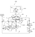
図1は、本実施形態に係る油圧回路100の構成を簡略化して示した説明図である。
この油圧回路100は、ベルト式無段変速機(CVT)のプーリー機構等(油圧作動機器)に油圧を供給する高圧回路200に対し、第1ポンプ10及び第2ポンプ20を逆止弁40を介して直列および並列に接続して油圧(オイル)を安定に供給する油圧回路である。特に、第2ポンプ20(モータM)の慣性モーメントに起因して発生する油圧の圧力振動を好適に抑制し、且つパイロット圧(圧力指示値)PCMDに対すフィードバック圧の追従性・応答性を向上させる。
FIG. 1 is an explanatory diagram showing a simplified configuration of a
The
本油圧回路100の構成として、第2ポンプ20の吐出口P21と高圧回路200とを連結する第1ライン1と、第1ポンプ10の吐出口P11と第1ライン1とを逆止弁40を介して連結する第2ライン2と、第1ライン1から分岐しレギュレータバルブ30に連結する第3ライン3と、第2ライン2から分岐しレギュレータバルブ30を介して低圧回路300に連結する第4ライン4と、第1ポンプ10の吐出口P11と第2ポンプ20の吸込口P22とを連結する第5ライン5と、レギュレータバルブ30とリニアソレノイドバルブ50とを連結する第6ライン6と、レギュレータバルブ30と蓄圧器80とを連結する第7ライン7と、高圧ライン1とリデューシングバルブ60とを連結する第8ライン8と、リニアソレノイドバルブ50とリデューシングバルブ60とを連結する第9ライン9と、エンジンEの回転動力によって常時駆動される第1ポンプ10と、モータMの回転動力によって必要に応じ駆動される第2ポンプ20と、高圧回路200の圧力PHをパイロット圧(圧力指示値PCMD)に等しくなるように調圧するレギュレータバルブ30と、オイルが第1ライン1から第2ライン2に流入することを阻止する逆止弁40と、レギュレータバルブ30に対しパイロット圧を供給するリニアソレノイドバルブ50と、リニアソレノイドバルブ50に元圧を供給するリデューシングバルブ60と、低圧回路300の圧力PLを所定圧(スプリング荷重圧)に調圧するPLレギュレータバルブ70と、ライン圧の圧力変動を吸収する蓄圧器80とを具備して構成されている。なお、P10,P20は、第1ポンプ10の吐出圧及び第2ポンプ20の差圧をそれぞれ示している。また、Q10,Q20は、第1ポンプ10及び第2ポンプ20の各吐出流量をそれぞれ示している。
As the configuration of the
また、説明の都合上、第4ライン4から分岐しフィードバック側及びパイロット側から弁体31に作用する内部系統は太線部分で表されている。以下、各構成について更に詳細に説明する。
For convenience of explanation, an internal system that branches from the
第1ライン1は、いわゆる高圧ラインである。第1ライン1と第2ライン2は、図中の点C1で連結している。詳細については、図4を参照しながら後述するが、高圧回路200に対し、最初は第1ポンプ10のみで第2ライン2を経由してオイルが供給される。その後、第1ポンプ10に加え、新たに第2ポンプ20が駆動され、第1ポンプ10及び第2ポンプ20を併用してオイルが供給される。その後、第2ポンプ吐出流量Q20が高圧回路200の消費流量QHに等しくなるとき、遮断弁40が閉状態となり、オイルは第2ポンプ20のみから高圧回路200に供給されるようになる。
The
第3ライン3は、いわゆるフィードバックラインである。レギュレータバルブ30は、調圧対象である高圧回路200の圧力PHを第3ライン3を経由して取り込む。
The
第4ライン4は、レギュレータバルブ30によって開閉される、いわゆる調圧ライン(絞り対象ライン)である。レギュレータバルブ30は、高圧回路200の圧力PHがパイロット圧PCMDより高い場合、第4ライン4に係る第3ポートP3開口を拡げて高圧回路200の圧力PHを下げるように調圧作動する。一方、高圧回路200の圧力PHがパイロット圧PCMDより低い場合は、第4ライン4に係る第3ポートP3開口を絞って高圧回路200の圧力PHを上げるように調圧作動する。
The
レギュレータバルブ30は、外部に5つのポートP1〜P5とを有し、第3ポートP3と第4ポートP4を連通する内部油路を有する。また、詳細については図2を参照しながら後述するが、第3ポートP3と第2ポートP2とがオリフィス油路31fを経由して常時連通している。また、第2ポートP2には第7ライン7を介して蓄圧器80が接続されている。それに加えて、第1ポンプ吐出圧P10がフィードバック側とパイロット側の両側から弁体31に常時作用している。これにより、第1ポンプ吐出圧P10の圧力変動成分のうち、時間変化が遅い成分は相殺されて、時間変化が早い成分だけが弁体31に直に殆ど時間遅れなくフィードバックされる。つまり、逆止弁40が閉状態の場合、第1ポンプ吐出圧P10の圧力変動成分のうち、時間変化の速い成分は第4ライン4を経由して弁体31に直に殆ど時間遅れなく伝わり、時間変化の遅い成分は第5ライン5、第2ポンプ20及び第3ライン3を経由して弁体31にフィードバックされることになる。
The
逆止弁40は、第1ポンプ吐出圧P10が高圧回路200の圧力PHより高くなる場合に限り、開状態となる。逆止弁40が開状態のとき、第2ポンプ20が非作動状態の場合、第1ポンプ10から吐出されるオイルが第2ライン2及び第1ライン1を経由して高圧回路200に供給される。第2ポンプ20が作動状態の場合、第1ポンプ10から吐出されるオイルは高圧回路200の他に第5ライン5を経由して第2ポンプ20の吸込口P22にも供給される。
The
他方、第2ポンプ20が駆動され、第2ポンプ吐出流量Q20が高圧回路200の消費流量QHに等しくなるとき、逆止弁40は閉状態となる。
On the other hand, when the
なお、第2ポンプ吐出口P21と点C1との間に、高圧回路200又は第1ポンプ10からのオイルの流入を阻止する逆止弁を別途設けても良い。
In addition, you may provide the check valve which blocks | prevents the inflow of the oil from the
リニアソレノイドバルブ50は、リデューシングバルブ60の出口圧を元圧として、リニアソレノイドによって圧力指令値(PCMD)に等しくなるように調圧し、その出力値をパイロット圧としてレギュレータバルブ30に出力する。
The
リデューシングバルブ60は、高圧回路200の圧力PHを元圧とし且つ出口圧をフィードバック圧として取り込み、フィードバック圧とスプリング荷重圧との力の釣り合いによって、出口圧をスプリング荷重圧に等しくなるように調圧する。
The reducing
第1ポンプ10は、容積型ポンプ、例えば内接ギヤポンプである。なお、第1ポンプ10がアンロード状態のとき、第1ポンプ吐出圧P10は、PLレギュレータバルブ70によって低圧回路300の圧力PLに等しくなるように調圧される。
The
第2ポンプ20は、吐出流量Q20とモータMの駆動電圧VMOTとの相関がリニアな関係となる。すなわち、モータMの駆動電圧VMOTを直線的に増加させると、第2ポンプ吐出流量Q20が直線的に増加し、モータMの駆動電圧VMOTを直線的に減少させると、第2ポンプ吐出流量Q20が直線的に減少する。
The
高圧回路200は、例えば、CVTのプーリー機構、およびCVTの前後進切換機構(前進用クラッチ、後進用ブレーキ)等の油圧作動機構に油圧を供給する油圧回路である。ドリブンプーリーレギュレータバルブ、ドリブンプーリーリニアソレノイド、ドライブプーリーレギュレータバルブ、ドライブプーリーリニアソレノイド、クラッチリデューシングバルブ等の複数のバルブ、オイルを移送する複数の配管等によって構成されている。
The high-
低圧回路300は、全体の回路システムのうち、潤滑など低圧でその用を満足する供給先、例えば潤滑回路,熱交換器,およびオイルフィルター等である。
The low-
図2は、本実施形態に係るレギュレータバルブ30を示す要部断面説明図である。なお、説明の都合上、各ポートに接続される油路(第3ライン3、第4ライン4、第7ライン7、第8ライン8)についても併せて図示されている。
FIG. 2 is an explanatory cross-sectional view of a main part showing the
レギュレータバルブ30は、弁体31とボディ32とスプリング33とから構成されている。弁体31の外周面には、軸方向左側から順に、第4ポートP4と第5ポートP5を隔てる(非連通状態にする)ための第1周状凸部31aと、第4ポートP4と第3ポートP3を連通する周状凹部31bと、第3ポートP3を絞る又は閉じるための段差部31cと、第2ポートP2と第3ポートP3を隔てる(非連通状態にする)ための第2周状凸部31dと、スプリング33を収納するための円筒部31eがそれぞれ形成されている。また、弁体31の内部には第3ポートP3と第2ポートP2とを常時連通するオリフィス油路31fが形成されている。
The
ボディ32には軸方向右側から順に、第8ライン8を介してパイロット圧(=圧力指示値PCMD)を導入するための第1ポートP1と、第7ライン7を介して蓄圧器80に接続するための第2ポートP2と、第4ライン4を経由して第1ポンプ10から吐出されるオイルを導入するための第3ポートP3と、第4ライン4を介して第1ポンプ10から吐出されるオイルを低圧回路300に流すための第4ポートP4と、第3ライン3を介して高圧回路200の圧力PHを導入するための第5ポートP5とがそれぞれ形成されている。さらに弁体31が突き当たる左エンド部32aと、スプリング33が突き当たる右エンド部32bとがそれぞれ形成されている。
The
第3ポートP3に流入し周状凹部31bを介して第4ポートP4から流出するオイル(主流)、すなわち第1ポンプ10から吐出され低圧回路300に供給されるオイル(油圧)については、2方向に分岐し一部は直接に第2周状凸部31dのフィードバック側に作用し、一部はオリフィス油路31fを通って蓄圧器80で反射して第2周状凸部31dのパイロット側に作用する。
The oil flowing into the third port P3 and flowing out from the fourth port P4 via the
特に、第2周状凸部31dは、外径Φ1と外径Φ2は互いに等しくなるように設定されている。つまり、第2周状凸部31dのフィードバック側の油圧作用面積S1と、パイロット側の油圧作用面積S2とは互いに等しくなるように設定されている。 In particular, the second circumferential convex portion 31d is set so that the outer diameter Φ1 and the outer diameter Φ2 are equal to each other. That is, the feedback hydraulic pressure area S1 and the pilot hydraulic pressure area S2 of the second circumferential convex portion 31d are set to be equal to each other.
その結果、第2周状凸部31dに作用する油圧の時間変化(周波数)に着目すると、フィードバック側の油圧は、時間変化の速い(高周波)油圧と時間変化の遅い(低周波)油圧が混在したものであるのに対し、パイロット側の油圧は時間変化の遅い(低周波)油圧となる。これは、オイルがオリフィス油路31fを通過し蓄圧器80で反射する過程で時間遅れが生じるためである。従って、これら主流から分岐した油圧が第2周状凸部31dで同時に作用する場合、時間変化の遅い油圧は、第2周状凸部31dにおいて相殺し合うことになる。その結果、第1ポンプ吐出圧P10の圧力変動成分の内、時間変化の速い油圧のみが第4ライン4を介して第2周状凸部31dに直に殆ど時間遅れなくフィードバックされることになる。
As a result, paying attention to the time change (frequency) of the oil pressure acting on the second circumferential convex portion 31d, the feedback side oil pressure is a mixture of oil pressure having a fast time change (high frequency) and oil pressure having a slow time change (low frequency). On the other hand, the pilot-side hydraulic pressure is a low-frequency hydraulic pressure that changes slowly over time. This is because time delay occurs in the process in which the oil passes through the orifice oil passage 31f and is reflected by the
つまり、時間変化の速い油圧は、第1ポンプ10から直接に時間遅れなく第4ライン4を介して弁体31にフィードバックされる。他方、時間変化の遅い油圧は、逆止弁40が閉状態の場合、第5ライン5、第2ポンプ20及び第3ライン3を経由して弁体31にフィードバックされる。つまり、第1ポンプ吐出圧P10の圧力変動成分は、時間変化毎に、適切な時間差で且つ別々の系統を介して適切に弁体31にフィードバックされる。これにより、弁体31が圧力変動に追従し、安定して調圧作動する。その結果、第2ポンプ20の本体及びモータMの慣性モーメントに起因する高圧回路200の圧力振動は抑えられる。同時に、フィードバック圧PHのパイロット圧PCMDに対する追従性・応答性が向上するようになる。
In other words, the hydraulic pressure that changes quickly is fed back directly from the
図3は、本実施形態に係るレギュレータバルブ30のバルブ位置を示す説明図である。図中の丸印は調圧箇所を示す。
FIG. 3 is an explanatory diagram showing the valve position of the
バルブ位置Aでは、初期スプリング荷重圧が高圧回路200の圧力PHを上回っており、弁体31がスプリング33に押されて左エンド部32aに突き当たっている状態である。この場合、第3ポートP3は閉状態である。第1ポンプ10は、オリフィス油路31fを経由して蓄圧器80に連通している。従って、弁体31の第2周状凸部31dに対しフィードバック側及びパイロット側から第1ポンプ吐出圧P10が作用している。
At the valve position A, the initial spring load pressure is higher than the pressure PH of the high-
バルブ位置Bは、段差部31cによって第3ポートP3が開けられた直後の状態である。バルブ位置Aにおいて、高圧回路200の圧力PHが初期スプリング荷重圧を上回るとき、弁体31は軸方向右側に移動し始める。弁体31が移動することにより第3ポートP3が開けられる。第3ポートP3が開けられることによって、第1ポンプ10から吐出されるオイルが低圧回路300へドレインされるようになる。これにより、調圧対象である高圧回路200の圧力PHが低下し弁体31が軸方向左側に移動して、圧力PHとパイロット圧PCMDが釣り合う位置で弁体31はバランスする。
The valve position B is a state immediately after the third port P3 is opened by the
バルブ位置Cは、第3ポートP3が開状態であるバルブ位置を示す説明図である。バルブ位置Bにおいて、フィードバック圧PHとパイロット圧が釣り合わない場合は、弁体31が軸方向右側に移動して第3ポートP3開口を押し広げる。
The valve position C is an explanatory view showing a valve position where the third port P3 is in an open state. When the feedback pressure PH and the pilot pressure are not balanced at the valve position B, the
バルブ位置Dは、高圧回路200の圧力PHがスプリング荷重圧を上回っており、弁体31が圧力PHに押されて右エンド部32bに突き当たっている状態である。この場合、高圧回路200の圧力PHがレギュレータバルブ30の調圧限界を超えている状態である。従って、第3ポートP3は全開状態となる。第1ポンプ10と低圧回路300は完全に連通状態となるため、第1ポンプ吐出圧P10は、PLレギュレータバルブ70によって低圧PLに調圧される。第1ポンプ10はアンロード状態となる。
The valve position D is a state in which the pressure PH of the high-
高圧回路200の圧力PHがレギュレータバルブ30の調圧範囲内まで低下すると、弁体31は軸方向左側に移動し始める。
When the pressure PH of the high-
以上の通り、フィードバック圧(高圧回路圧)PHが増加するにつれて、弁体31はバルブ位置Bを中心にバランスして第3ポートP3からオイルをドレインしながらフィードバック圧PHをパイロット圧PCMDに等しくなるように調圧する。そして、レギュレータバルブ30が第3ポートP3からオイルをドレインしてもなお、フィードバック圧PHがパイロット圧に等しくならず上昇する場合は、弁体31は更に軸方向右側に移動して第3ポートP2開口を更に押し広げる。そして、スプリング33の収縮量が最大となっても高圧回路200の圧力PHがパイロット圧PCMDに等しくならない場合は、第3ポートP3が全開状態となり、第1ポンプ10はアンロード状態となる。この場合、第1ポンプ吐出圧P10から吐出されるオイルは第4ライン4を経由して低圧回路300に排出される。
As described above, as the feedback pressure (high-pressure circuit pressure) PH increases, the
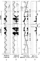
図4は、本油圧回路100の動作を示すグラフである。なお、各グラフの横軸は統一した時間軸を示す。縦軸は、上から順に高圧回路圧PH及び圧力指示値PCMD、ポンプ圧力P10,P20及び低圧回路圧PL、第2ポンプ吐出流量Q20及び逆止弁流量Q40及び高圧回路の消費流量QH、並びにレギュレータバルブ30のバルブ位置の各時系列変化をそれぞれ示している。各縦軸の目盛りは相対値である。
FIG. 4 is a graph showing the operation of the
動作条件(運転条件)として、図4(a)に示されるように、本油圧回路100の安定性を確認するために圧力指示値(パイロット圧)PCMDは階段状に変化させている。また、図4(c)に示されるように、高圧回路の消費流量QHについては正弦波状に変化させている。更に、図4(c)に部分的に示されるように、第2ポンプ20を駆動するモータMの駆動電圧VMOTについては直線的に上昇・下降させている。また、図示されてはいないが、第1ポンプ吐出流量Q10については一定値としている。
As an operation condition (operation condition), as shown in FIG. 4A, in order to confirm the stability of the
動作結果として、図4(a)に示されるように、高圧回路圧PHは圧力指示値(パイロット圧)PCMDに殆ど等しくなることが分かる。つまり、レギュレータバルブ30はパイロット圧の変化に素早く反応することが分かる。また、高圧回路圧PHが安定していることが分かる。
As a result of the operation, as shown in FIG. 4A, it can be seen that the high pressure circuit pressure PH is almost equal to the pressure command value (pilot pressure) PCMD. That is, it can be seen that the
なお、時刻T3からT4において、高圧回路圧PHは圧力指示値(パイロット圧)PCMDに追従していない。これは、第2ポンプ差圧P20が増大して(モータMの駆動動力が増大して)、高圧回路圧PHがレギュレータバルブ30の調圧限界を超えたためである。この場合、レギュレータバルブ30が開放状態(バルブ位置D)となり、第1ポンプ10がアンロード状態となる。その結果、図4(b)に示されるように、第1ポンプ吐出圧P10は低圧回路圧PLに調圧される。高圧回路圧PHは、第2ポンプ吐出圧P20と低圧回路圧PLとを加えた値(=P20+PL)に等しくなる。
From time T3 to T4, the high-pressure circuit pressure PH does not follow the pressure command value (pilot pressure) PCMD. This is because the second pump differential pressure P20 increases (the driving power of the motor M increases) and the high-pressure circuit pressure PH exceeds the pressure regulation limit of the
次に図4(b)について説明する。時刻T0からT1において、第2ポンプ20は非作動状態である。この場合、第1ポンプ10のみが高圧回路200にオイルを供給している。従って、第1ポンプ吐出圧P10は高圧回路圧PHに殆ど等しくなる(近似する)。
Next, FIG. 4B will be described. From time T0 to T1, the
時刻T1からT2において、第2ポンプ20は作動状態であるが、第2ポンプ差圧P20はゼロとなる。これは、第1ポンプ10から吐出されるオイルが第2ライン2を経由して高圧回路に供給され、逆止弁40の前後差圧(=第2ポンプ差圧P20)がゼロとなるためである。その結果、第1ポンプ吐出圧P10が高圧回路圧PHに殆ど等しくなる(近似する)。
From time T1 to T2, the
時刻T2において、逆止弁40が閉状態となる。これにより、高圧回路圧PH、第1ポンプ吐出圧P10及び第2ポンプ差圧P20との間には、P10+P20=PH(=PCMD)、という関係が成立する。従って、時刻T2からT3において、第2ポンプ差圧P20がゼロから増加する場合、第1ポンプ吐出圧P10は減少する。逆に、第2ポンプ差圧P20が減少する場合、第1ポンプ吐出圧P10は増加する。
At time T2, the
特に、高圧回路200の消費流量QH(図4(c))が急激に増加する場合、第2ポンプ差圧P20は低下するが、高圧回路圧PHは圧力指示値(パイロット圧)PCMDに追従していることが分かる。
In particular, when the consumption flow rate QH (FIG. 4C) of the
時刻T3からT4については、上述した通りである。時刻T4からT6におけるポンプ圧力は、時刻T1から時刻T3におけるポンプ圧力と逆の動作を示すため、説明は省略する。 Times T3 to T4 are as described above. Since the pump pressure from time T4 to T6 shows the reverse operation of the pump pressure from time T1 to time T3, description thereof is omitted.
次に、図4(c)について説明する。時刻T0からT1において、第2ポンプ20は非作動状態であり、第1ポンプ10のみが高圧回路200へ供給する。そのため、第1ポンプ10から吐出されるオイルは全て逆止弁40を経由して高圧回路200に供給される。従って、逆止弁流量Q40は高圧回路200の消費流量QHに等しくなる。
Next, FIG. 4C will be described. From time T0 to T1, the
時刻T1において、第2ポンプ20が駆動され始める。これにより、高圧回路200の消費流量QH、逆止弁流量Q40及び第2ポンプ吐出流量Q20の間には、Q40+Q20=QH、という関係が成立する。これにより、第2ポンプ吐出流量Q20がゼロから直線的に増加する場合、逆止弁流量Q40は減少する。
At time T1, the
時刻T2において、逆止弁流量Q40がゼロ(逆止弁40が閉状態)となる。従って、時刻T2から時刻T5において、Q40=0且つQ20=QH、という関係が成立する。時刻T5において、逆止弁流量Q40がゼロから増加状態(逆止弁40が開状態)となり、第2ポンプ吐出流量Q20が直線的に減少する。
At time T2, the check valve flow rate Q40 becomes zero (the
図4(d)について説明する。時刻T0からT3、及び時刻T4からT6において、レギュレータバルブ30はバルブ位置Bを中心にバランスして高圧回路圧PHを圧力指示値(パイロット圧)PCMDに等しくなるように調圧作動している。一方、第2ポンプ差圧P20が増大して、高圧回路圧PHがレギュレータバルブ30の調圧限界を超える時刻T3からT4においては、レギュレータバルブ30はバルブ位置Dを中心にバランスして、第1ポンプ10をアンロード状態にする。
FIG. 4D will be described. From time T0 to T3 and from time T4 to T6, the
以上の説明を簡潔にまとめると、時刻T0からT1では、モータ駆動電圧VMOTがゼロなので第2ポンプ差圧P20、第2ポンプ吐出流量Q20はともにゼロである。モータ駆動電圧VMOTの増加に伴い、まず第2ポンプ吐出流量Q20がゼロから増加する。逆止弁流量Q40は、高圧回路200の消費流量QHから第2ポンプ吐出流量Q20を引いたものになるから、第2ポンプ吐出流量Q20の増加に伴い減少していく。
To summarize the above description, from time T0 to T1, since the motor drive voltage VMOT is zero, the second pump differential pressure P20 and the second pump discharge flow rate Q20 are both zero. As the motor drive voltage VMOT increases, the second pump discharge flow rate Q20 first increases from zero. Since the check valve flow rate Q40 is obtained by subtracting the second pump discharge flow rate Q20 from the consumption flow rate QH of the high-
逆止弁流量Q40がゼロになると、逆止弁40が閉じて、第2ポンプ20に圧力差が生じて第2ポンプ差圧P20が増加する。このとき、第2ポンプ吐出流量Q20は高圧回路200の消費流量QHに合わせて変化する。第1ポンプ吐出圧P10と第2ポンプ差圧P20を足したものが高圧回路圧PHなので、第2ポンプ差圧P20が上昇すると第1ポンプ吐出圧P10は減少してやがて低圧回路圧PLに等しくなる。
When the check valve flow rate Q40 becomes zero, the
第2ポンプ20に圧力差が生じてから第1ポンプ吐出圧P10が低圧回路圧PLに等しくなるまでの間は、第2ポンプ20の吐出により第1ポンプ10は漸進的にアンロードされる。モータ駆動電圧VMOTが減少すると、増加と逆の動作により第2ポンプ吐出流量Q20がゼロまで戻る。
The
レギュレータバルブ30は、1付近(バルブ位置B)で調圧作動し、4付近(バルブ位置D)で開放している。図4(b)に対照すると調圧時は第1ポンプ吐出圧P10は低圧回路圧PLより高くなり、開放時は第1ポンプ吐出圧P10は低圧回路圧PLに等しくなることが分かる。また図4(a)に対照すると調圧時は高圧回路圧PHと圧力指示圧(パイロット圧)PCMDはほぼ等しくなり、開放時は高圧回路圧PHが圧力指示圧(パイロット圧)PCMDを超えることが分かる。
The
以上、本発明の油圧回路100によれば、レギュレータバルブ30が圧力指示値(パイロット圧)PCMDに素早く応答して、調圧対象である高圧回路圧PHを圧力指示値PCMDに等しくなるように調圧作動する。
As described above, according to the
そして、第1ポンプ吐出圧P10が変動する場合、圧力変動成分の内、油圧の時間変化の速い成分は第4ライン4を経由して直に殆ど時間遅れなく弁体31にフィードバックされ、油圧の時間変化の遅い成分は第5ライン5、第2ポンプ20及び第3ライン3を経由して弁体31にフィードバックされる。つまり、第1ポンプ吐出圧P10の油圧変動が、時間変化毎に、適切な時間差で且つ別々の系統を介して弁体31に適切にフィードバックされることになる。これにより、弁体31が油圧変動に追従し、安定して調圧作動するようになる。その結果、圧力振動、例えば第2ポンプ20の慣性モーメントに起因する圧力振動は発生しなくなる。
Then, when the first pump discharge pressure P10 fluctuates, the component of the pressure fluctuation component whose hydraulic pressure changes quickly is fed back to the
また、調圧対象であるフィードバック圧PHが圧力指示値(パイロット圧)PCMDに好適に追従する。そのため、本油圧回路100をベルト式無段変速機に適用する場合、ベルト滑りを防ぐための余剰油圧を減らすことが可能となる。これにより、ポンプ駆動動力が減り、ひいては全体の動力損失を減らすことが可能となる。
In addition, the feedback pressure PH that is a pressure adjustment target suitably follows the pressure command value (pilot pressure) PCMD. Therefore, when this
1 第1ライン
2 第2ライン
3 第3ライン
4 第4ライン(調圧ライン)
5 第5ライン
6 第6ライン
7 第7ライン
8 第8ライン
9 第9ライン
10 第1ポンプ
20 第2ポンプ
30 レギュレータバルブ(圧力調整弁)
40 逆止弁
50 リニアソレノイドバルブ
60 リデューシングバルブ
70 PLレギュレータバルブ
80 蓄圧器
100 油圧回路
200 高圧回路
300 低圧回路
1
5 5th line 6
40
Claims (9)
必要に応じ駆動される第2ポンプと、
前記第1ポンプの吐出口に連通する開閉対象である調圧ラインを絞りながら、調圧対象であるフィードバック圧と圧力指示値であるパイロット圧との力の釣り合いによって該フィードバック圧を所定圧に調圧する圧力調整弁とを備え、
前記第1ポンプと前記第2ポンプとが少なくとも1つの逆止弁を介して直列および並列に接続されて油圧作動機器に油圧を供給する油圧供給装置であって、
前記圧力調整弁は、外周面に凹凸が形成された弁体、該弁体が摺動するボディ、及び該弁体を付勢するスプリングによって構成され、前記調圧ライン中を流れるオイルを主流から2方向に分岐させ、前記弁体の凸部において軸方向に沿って対向する形態で且つパイロット側のオイルがフィードバック側のオイルよりも時間的に遅れて作用するように構成されていることを特徴とする油圧供給装置。 A first pump that is always driven;
A second pump driven as needed;
The feedback pressure is adjusted to a predetermined pressure by balancing the feedback pressure as the pressure adjustment target and the pilot pressure as the pressure indication value while narrowing the pressure adjustment line as the opening and closing target communicating with the discharge port of the first pump. A pressure regulating valve that presses,
A hydraulic pressure supply device in which the first pump and the second pump are connected in series and in parallel via at least one check valve to supply hydraulic pressure to a hydraulically operated device;
The pressure regulating valve is constituted by a valve body having an uneven surface formed on an outer peripheral surface, a body on which the valve body slides, and a spring that biases the valve body, and the oil flowing in the pressure adjusting line is removed from the mainstream. It is branched in two directions, and is configured such that the oil on the pilot side acts with a time delay from the oil on the feedback side, in a form facing the axial direction at the convex portion of the valve body. Hydraulic supply device.
前記圧力調整弁は、外周面に凹凸が形成された弁体、該弁体が摺動するボディ、及び該弁体を付勢するスプリングによって構成され、前記調圧ライン中を流れるオイルを主流から2方向に分岐させ、前記弁体の凸部において軸方向に沿って対向する形態で且つパイロット側のオイルがフィードバック側のオイルよりも時間的に遅れて作用するように構成されていることを特徴とする圧力調整弁。 A pressure regulating valve that regulates the feedback pressure to a predetermined pressure by balancing the force of the feedback pressure to be regulated and the pilot pressure that is the pressure indication value while narrowing the regulation line to be opened and closed,
The pressure regulating valve is constituted by a valve body having an uneven surface formed on an outer peripheral surface, a body on which the valve body slides, and a spring that biases the valve body, and the oil flowing in the pressure adjusting line is removed from the mainstream. It is branched in two directions, and is configured such that the oil on the pilot side acts with a time delay from the oil on the feedback side, in a form facing the axial direction at the convex portion of the valve body. And pressure regulating valve.
Priority Applications (1)
| Application Number | Priority Date | Filing Date | Title |
|---|---|---|---|
| JP2016124007A JP2017227271A (en) | 2016-06-22 | 2016-06-22 | Oil pressure supply device and pressure regulating valve |
Applications Claiming Priority (1)
| Application Number | Priority Date | Filing Date | Title |
|---|---|---|---|
| JP2016124007A JP2017227271A (en) | 2016-06-22 | 2016-06-22 | Oil pressure supply device and pressure regulating valve |
Publications (1)
| Publication Number | Publication Date |
|---|---|
| JP2017227271A true JP2017227271A (en) | 2017-12-28 |
Family
ID=60891267
Family Applications (1)
| Application Number | Title | Priority Date | Filing Date |
|---|---|---|---|
| JP2016124007A Pending JP2017227271A (en) | 2016-06-22 | 2016-06-22 | Oil pressure supply device and pressure regulating valve |
Country Status (1)
| Country | Link |
|---|---|
| JP (1) | JP2017227271A (en) |
Cited By (2)
| Publication number | Priority date | Publication date | Assignee | Title |
|---|---|---|---|---|
| CN111527331A (en) * | 2018-02-23 | 2020-08-11 | 舍弗勒技术股份两合公司 | Fluid system with a pressure accumulator for pressing a disk stack in a continuously adjustable endless drive and continuously adjustable endless drive |
| JP7334462B2 (en) | 2019-05-14 | 2023-08-29 | 株式会社アイシン | hydraulic controller |
-
2016
- 2016-06-22 JP JP2016124007A patent/JP2017227271A/en active Pending
Cited By (4)
| Publication number | Priority date | Publication date | Assignee | Title |
|---|---|---|---|---|
| CN111527331A (en) * | 2018-02-23 | 2020-08-11 | 舍弗勒技术股份两合公司 | Fluid system with a pressure accumulator for pressing a disk stack in a continuously adjustable endless drive and continuously adjustable endless drive |
| JP2020535366A (en) * | 2018-02-23 | 2020-12-03 | シェフラー テクノロジーズ アー・ゲー ウント コー. カー・ゲーSchaeffler Technologies AG & Co. KG | Fluid system with accumulator for disc set pressing in continuously variable transmission and continuously variable transmission |
| CN111527331B (en) * | 2018-02-23 | 2021-11-05 | 舍弗勒技术股份两合公司 | Infinitely adjustable endless drive and fluid system for such a drive |
| JP7334462B2 (en) | 2019-05-14 | 2023-08-29 | 株式会社アイシン | hydraulic controller |
Similar Documents
| Publication | Publication Date | Title |
|---|---|---|
| JP5250624B2 (en) | Force feedback poppet valve with integrated pressure compensator | |
| US8360907B2 (en) | Hydraulic control system of continuously variable transmission | |
| US9829091B2 (en) | Continuously variable transmission with a hydraulic control system | |
| JP5053970B2 (en) | Hydraulic pump device for continuously variable transmission | |
| JP2017227271A (en) | Oil pressure supply device and pressure regulating valve | |
| JP5668419B2 (en) | Hydraulic control device | |
| RU2624926C1 (en) | Proportional valve of management of hydromechanical transfer frequencies | |
| JP2016044806A (en) | Hydraulic supply system changeover mechanism | |
| JP2011163393A (en) | Hydraulic control device, and control device of belt type continuously variable transmission | |
| JP6405079B2 (en) | Hydraulic control circuit | |
| US5243820A (en) | Hydraulic circuit with compensator valve biased with highest pressure acting on actuators | |
| US20160011601A1 (en) | Hydraulic control system | |
| CN109642666B (en) | Control method of continuously variable transmission | |
| JP5741711B2 (en) | Hydraulic control device for automatic transmission | |
| WO2014156309A1 (en) | Continuously variable transmission control device and control method | |
| JP2018200071A (en) | Hydraulic controller | |
| JP7091271B2 (en) | Hydraulic control device | |
| JP5900301B2 (en) | Hydraulic control device | |
| JP2017190851A (en) | Hydraulic circuit for hydraulic equipment | |
| JP2017207116A (en) | Hydraulic circuit for hydraulic equipment | |
| JP2017207191A (en) | Hydraulic circuit for hydraulic equipment | |
| JP2011247290A (en) | Hydraulic control device of belt-type continuously variable transmission | |
| JP2011052797A (en) | Hydraulic controller for belt type continuously variable transmission | |
| JP6610598B2 (en) | Hydraulic transmission device for automatic transmission | |
| JP5282771B2 (en) | Hydraulic control device for automatic transmission |