JP2017190832A - Control device of power transmission device for vehicle - Google Patents

Control device of power transmission device for vehicle Download PDF

Info

Publication number
JP2017190832A
JP2017190832A JP2016080677A JP2016080677A JP2017190832A JP 2017190832 A JP2017190832 A JP 2017190832A JP 2016080677 A JP2016080677 A JP 2016080677A JP 2016080677 A JP2016080677 A JP 2016080677A JP 2017190832 A JP2017190832 A JP 2017190832A
Authority
JP
Japan
Prior art keywords
clutch
lockup
friction plate
temperature
control
Prior art date
Legal status (The legal status is an assumption and is not a legal conclusion. Google has not performed a legal analysis and makes no representation as to the accuracy of the status listed.)
Granted
Application number
JP2016080677A
Other languages
Japanese (ja)
Other versions
JP6515862B2 (en
Inventor
圭吾 松原
Keigo Matsubara
圭吾 松原
佐川 歩
Ayumi Sagawa
歩 佐川
Current Assignee (The listed assignees may be inaccurate. Google has not performed a legal analysis and makes no representation or warranty as to the accuracy of the list.)
Toyota Motor Corp
Original Assignee
Toyota Motor Corp
Priority date (The priority date is an assumption and is not a legal conclusion. Google has not performed a legal analysis and makes no representation as to the accuracy of the date listed.)
Filing date
Publication date
Application filed by Toyota Motor Corp filed Critical Toyota Motor Corp
Priority to JP2016080677A priority Critical patent/JP6515862B2/en
Publication of JP2017190832A publication Critical patent/JP2017190832A/en
Application granted granted Critical
Publication of JP6515862B2 publication Critical patent/JP6515862B2/en
Expired - Fee Related legal-status Critical Current
Anticipated expiration legal-status Critical

Links

Images

Landscapes

  • Control Of Fluid Gearings (AREA)
  • Hydraulic Clutches, Magnetic Clutches, Fluid Clutches, And Fluid Joints (AREA)

Abstract

PROBLEM TO BE SOLVED: To provide a control device of a power transmission device for a vehicle which improves the estimation accuracy of a temperature of a friction material compared with a conventional device.SOLUTION: A friction material temperature estimation part 84 comprises: a calorific power estimation part 84a for estimating the calorific power Qh of a first friction plate 38 and a second friction plate 44 of a lockup clutch 32; and a heat radiation estimation part 84b for estimating heat radiation amounts Qc of the first friction plate 38 and the second friction plate 44 of the lockup clutch. The heat radiation estimation part 84b estimates the heat radiation amount Qc estimated by the heat radiation amount estimation part 84b so as to become large as a temperature difference ΔT(°C) between actual estimated temperatures T0 (°C) of the first friction plate 38 and the second friction plate 44 of the lockup clutch 32 and an actual first oil temperature T1 (°C) at a downstream side of the lockup clutch 32 is large, and a turbine rotation number Nt of a torque converter 20 is large.SELECTED DRAWING: Figure 1

Description

本発明は、変速機の係合要素の摩擦材或いはロックアップクラッチの摩擦材の温度を推定する車両用動力伝達装置の制御装置において、その摩擦材の温度の推定精度を向上させる技術に関するものである。   The present invention relates to a technique for improving the accuracy of estimation of the temperature of a friction material in a control device for a vehicle power transmission device that estimates the temperature of a friction material of an engagement element of a transmission or a friction material of a lock-up clutch. is there.

複数の係合要素を係合又は解放することで変速段を形成する変速機、或いは、ロックアップクラッチの係合又は解放により入力部材および出力部材を直結又は解放可能な流体継手を備えた車両用動力伝達装置において、前記係合要素或いは前記ロックアップクラッチの摩擦材の温度を推定する摩擦材温度推定部を備える車両用動力伝達装置の制御装置が知られている。例えば、特許文献1に記載された車両用動力伝達装置の制御装置がそれである。特許文献1では、変速機の係合要素における摩擦材の温度を推定するための計算方法が開示されている。その計算方法では、摩擦材で発熱する発熱量を示す発熱項と摩擦材から放熱する放熱量を示す放熱項とを別々に計算すると共に、その放熱項においては摩擦材の周りを通過する潤滑油量に基づいて放熱量を計算することで摩擦材の温度の推定精度を向上させている。また、特許文献1では、上記潤滑油量のパラメータとしてクラッチ面圧、ライン圧、油粘性を考慮している。   For a vehicle having a transmission that forms a gear stage by engaging or releasing a plurality of engaging elements, or a fluid coupling that can directly connect or release an input member and an output member by engaging or releasing a lockup clutch 2. Description of the Related Art In a power transmission device, a control device for a vehicle power transmission device is known that includes a friction material temperature estimation unit that estimates a temperature of a friction material of the engagement element or the lockup clutch. For example, the control device for a vehicle power transmission device described in Patent Document 1 is the same. Patent Document 1 discloses a calculation method for estimating the temperature of a friction material in an engagement element of a transmission. In the calculation method, a heat generation term indicating the amount of heat generated by the friction material and a heat dissipation term indicating the amount of heat released from the friction material are calculated separately, and in that heat dissipation term, the lubricating oil that passes around the friction material is calculated. The accuracy of estimating the temperature of the friction material is improved by calculating the amount of heat release based on the amount. Moreover, in patent document 1, the clutch surface pressure, the line pressure, and the oil viscosity are considered as the parameters of the lubricating oil amount.

国際公開第2014/115424号International Publication No. 2014/115424

ところで、上記特許文献1では、上記計算方法で温度を推定する摩擦材は変速機の係合要素であるので、その係合要素をスリップ状態で使用する期間は例えばロックアップクラッチに比べて比較的短い。このため、上記特許文献1の計算方法でも精度を確保しながら摩擦材の温度を推定することができるが、(例えばロックアップクラッチのように)スリップ状態で使用する期間が比較的長い場合には、上記特許文献1のような計算方法では摩擦材の温度を推定する推定精度が充分に得られないという問題があった。   By the way, in Patent Document 1, since the friction material whose temperature is estimated by the above calculation method is an engagement element of the transmission, the period during which the engagement element is used in the slip state is relatively smaller than that of, for example, a lockup clutch. short. For this reason, the temperature of the friction material can be estimated with the calculation method disclosed in Patent Document 1 while ensuring accuracy. However, when the period of use in a slip state is relatively long (for example, like a lock-up clutch) The calculation method as described in Patent Document 1 has a problem that the estimation accuracy for estimating the temperature of the friction material cannot be obtained sufficiently.

本発明は、以上の事情を背景として為されたものであり、その目的とするところは、摩擦材の温度の推定精度を従来に比較して向上させる車両用動力伝達装置の制御装置を提供することにある。   The present invention has been made against the background of the above circumstances, and an object of the present invention is to provide a control device for a vehicle power transmission device that improves the estimation accuracy of the temperature of the friction material as compared with the conventional one. There is.

第1発明の要旨とするところは、(a)複数の係合要素を係合又は解放することで変速段を形成する変速機、或いは、ロックアップクラッチの係合又は解放により入力部材および出力部材を直結又は解放可能な流体継手を備えた車両用動力伝達装置において、前記係合要素或いは前記ロックアップクラッチの摩擦材の温度を推定する摩擦材温度推定部を備える車両用動力伝達装置の制御装置であって、(b)前記摩擦材温度推定部は、前記摩擦材の発熱量を推定する発熱量推定部と、前記摩擦材の放熱量を推定する放熱量推定部とを備え、(c)前記放熱量推定部は、実際の前記摩擦材の推定温度と前記ロックアップクラッチの下流の実際の油温との差温が大きいほど、かつ、前記流体継手のタービン回転数が大きいほど、前記放熱量推定部で推定される放熱量が大きくなるように推定することにある。   The gist of the first invention is (a) a transmission that forms a gear stage by engaging or releasing a plurality of engaging elements, or an input member and an output member by engaging or releasing a lockup clutch. In the vehicle power transmission device provided with a fluid coupling capable of directly coupling or releasing, a control device for a vehicle power transmission device including a friction material temperature estimation unit for estimating the temperature of the friction material of the engagement element or the lockup clutch (B) The friction material temperature estimation unit includes a heat generation amount estimation unit that estimates a heat generation amount of the friction material, and a heat release amount estimation unit that estimates a heat release amount of the friction material, and (c) The heat radiation amount estimation unit increases the difference between the actual estimated temperature of the friction material and the actual oil temperature downstream of the lockup clutch, and the greater the turbine rotational speed of the fluid coupling, the greater the release amount. Heat estimation unit In the heat radiation amount estimated it is estimated to be larger.

第1発明によれば、前記摩擦材温度推定部は、前記摩擦材の発熱量を推定する発熱量推定部と、前記摩擦材の放熱量を推定する放熱量推定部とを備え、前記放熱量推定部は、実際の前記摩擦材の推定温度と前記ロックアップクラッチの下流の実際の油温との差温が大きいほど、かつ、前記流体継手のタービン回転数が大きいほど、前記放熱量推定部で推定される放熱量が大きくなるように推定する。このため、実際の前記摩擦材の推定温度と前記ロックアップクラッチの下流の実際の油温との差温が大きく、前記油温が実際の前記摩擦材の推定温度より低くければ、その低い油温の潤滑油が前記摩擦材に供給されることで、前記摩擦材から放熱する放熱量が大きくなって前記摩擦材が冷却され易くなる。また、前記流体継手のタービン回転数が高いほど、前記変速機の係合要素或いは前記ロックアップクラッチの回転数が比例して高くなるので、前記係合要素或いは前記ロックアップクラッチにおける潤滑油の攪拌速度が上昇し、前記摩擦材から放熱する放熱量が大きくなって前記摩擦材が冷却され易くなる。これにより、前記放熱量推定部では、従来のように単純に摩擦材を通過する潤滑油量に基いて前記摩擦材から放熱する放熱量を推定するだけではなく、前記摩擦材を通過する潤滑油の状態を考慮して放熱量を推定するので、実際の前記摩擦材の温度傾向に即した推定が可能となり、前記摩擦材の温度の推定精度を従来に比較して向上させられる。   According to the first invention, the friction material temperature estimation unit includes a heat generation amount estimation unit that estimates a heat generation amount of the friction material, and a heat release amount estimation unit that estimates a heat release amount of the friction material, and the heat release amount The estimation unit is configured to increase the heat radiation amount estimation unit as the difference temperature between the actual estimated temperature of the friction material and the actual oil temperature downstream of the lockup clutch increases and as the turbine rotational speed of the fluid coupling increases. Estimate so that the amount of heat radiation estimated in step 1 increases. Therefore, if the temperature difference between the actual estimated temperature of the friction material and the actual oil temperature downstream of the lockup clutch is large and the oil temperature is lower than the actual estimated temperature of the friction material, the lower oil By supplying warm lubricating oil to the friction material, the amount of heat released from the friction material increases and the friction material is easily cooled. Further, the higher the turbine rotational speed of the fluid coupling, the higher the rotational speed of the engagement element or the lockup clutch of the transmission is proportionally increased. Therefore, the agitation of the lubricating oil in the engagement element or the lockup clutch is increased. As the speed increases, the amount of heat released from the friction material increases, and the friction material is easily cooled. Thus, the heat radiation amount estimation unit simply estimates the heat radiation amount radiated from the friction material based on the amount of the lubricating oil that passes through the friction material as in the conventional case, and the lubricating oil that passes through the friction material. Therefore, the heat radiation amount is estimated in consideration of the above state, so that it is possible to estimate in accordance with the actual temperature trend of the friction material, and the estimation accuracy of the temperature of the friction material can be improved as compared with the conventional case.

本発明が適用される車両の概略構成を説明する図であると共に、車両における各種制御の為の制御機能を説明する図である。It is a figure explaining the schematic structure of the vehicle to which this invention is applied, and is a figure explaining the control function for various control in a vehicle. 図1の車両に設けられたトルクコンバータや自動変速機の一例を説明する骨子図である。FIG. 2 is a skeleton diagram illustrating an example of a torque converter and an automatic transmission provided in the vehicle of FIG. 1. 図2のトルクコンバータの断面図である。It is sectional drawing of the torque converter of FIG. 図2の自動変速機の変速作動とそれに用いられる油圧式摩擦係合装置の作動の組み合わせとの関係を説明する係合作動表である。3 is an engagement operation table for explaining a relationship between a shift operation of the automatic transmission of FIG. 2 and a combination of operations of a hydraulic friction engagement device used therefor. 図2のトルクコンバータに設けられたロックアップクラッチの作動を制御するリニアソレノイドバルブ等に関する油圧制御回路の要部の一例を示す回路図である。FIG. 3 is a circuit diagram illustrating an example of a main part of a hydraulic control circuit related to a linear solenoid valve or the like that controls the operation of a lockup clutch provided in the torque converter of FIG. 2. 図1の電子制御装置に設けられた発熱ゲイン設定部において、クラッチ伝達トルクから発熱ゲインを設定するマップの一例を示す図である。It is a figure which shows an example of the map which sets a heat gain from a clutch transmission torque in the heat gain setting part provided in the electronic controller of FIG. 図1の電子制御装置に設けられた発熱ゲイン設定部において、エンジン回転数とタービン回転数との差回転から発熱ゲインを設定するマップの一例を示す図である。It is a figure which shows an example of the map which sets a heat gain from the difference rotation of an engine speed and a turbine speed in the heat gain setting part provided in the electronic controller of FIG. 図1の電子制御装置に設けられた放熱ゲイン設定部において、タービン回転数から放熱ゲインを設定するマップの一例を示す図である。It is a figure which shows an example of the map which sets a heat dissipation gain from a turbine speed in the heat gain setting part provided in the electronic controller of FIG. 図1の電子制御装置に設けられた放熱ゲイン設定部において、ロックアップクラッチの摩擦材の推定温度とロックアップクラッチの下流の油温との差温から放熱ゲインを設定するマップの一例を示す図である。The figure which shows an example of the map which sets a heat dissipation gain from the difference temperature of the estimated temperature of the friction material of a lockup clutch, and the oil temperature of the downstream of a lockup clutch in the heat dissipation gain setting part provided in the electronic controller of FIG. It is. 図1の電子制御装置において、フレックスロックアップ制御の実施中の制御作動の一例を説明するフローチャートである。2 is a flowchart illustrating an example of a control operation during execution of flex lockup control in the electronic control device of FIG. 1.

以下、本発明の実施例を図面を参照しつつ詳細に説明する。なお、以下の実施例において図は適宜簡略化或いは変形されており、各部の寸法比および形状等は必ずしも正確に描かれていない。   Hereinafter, embodiments of the present invention will be described in detail with reference to the drawings. In the following embodiments, the drawings are appropriately simplified or modified, and the dimensional ratios, shapes, and the like of the respective parts are not necessarily drawn accurately.

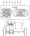
図1は、本発明が適用された車両10の概略構成を説明する図であると共に、車両10における各種制御の為の制御系統の要部を説明する図である。図1において、車両10は、エンジン12と、駆動輪14と、エンジン12と駆動輪14との間の動力伝達経路に設けられた車両用動力伝達装置16(以下、動力伝達装置16という)とを備えている。動力伝達装置16は、車体に取り付けられる非回転部材としてのケース18(図2参照)内に配設されたトルクコンバータ(流体継手)20および自動変速機(変速機)22と、自動変速機22の出力回転部材である変速機出力ギヤ24がリングギヤ26aに連結された差動歯車装置(ディファレンシャルギヤ)26と、差動歯車装置26に連結された一対の車軸28等とを備えている。動力伝達装置16において、エンジン12から出力される動力は、トルクコンバータ20、自動変速機22、差動歯車装置26、及び車軸28等を順次介して駆動輪14へ伝達される。   FIG. 1 is a diagram illustrating a schematic configuration of a vehicle 10 to which the present invention is applied, and a diagram illustrating a main part of a control system for various controls in the vehicle 10. In FIG. 1, a vehicle 10 includes an engine 12, drive wheels 14, a vehicle power transmission device 16 (hereinafter referred to as a power transmission device 16) provided in a power transmission path between the engine 12 and the drive wheels 14. It has. The power transmission device 16 includes a torque converter (fluid coupling) 20 and an automatic transmission (transmission) 22 disposed in a case 18 (see FIG. 2) as a non-rotating member attached to the vehicle body, and an automatic transmission 22. A transmission output gear 24, which is an output rotating member, is provided with a differential gear device (differential gear) 26 connected to a ring gear 26a, a pair of axles 28 connected to the differential gear device 26, and the like. In the power transmission device 16, the power output from the engine 12 is transmitted to the drive wheels 14 via the torque converter 20, the automatic transmission 22, the differential gear device 26, the axle 28 and the like in order.

エンジン12は、車両10の動力源であり、例えばガソリンエンジンやディーゼルエンジン等の内燃機関である。   The engine 12 is a power source of the vehicle 10 and is, for example, an internal combustion engine such as a gasoline engine or a diesel engine.

図2は、トルクコンバータ20や自動変速機22の一例を説明する骨子図である。なお、トルクコンバータ20や自動変速機22等は、自動変速機22の入力回転部材である変速機入力軸30の軸心RCに対して略対称的に構成されており、図2ではその軸心RCの下半分が省略されている。   FIG. 2 is a skeleton diagram illustrating an example of the torque converter 20 and the automatic transmission 22. The torque converter 20, the automatic transmission 22, and the like are configured substantially symmetrically with respect to the axis RC of the transmission input shaft 30 that is an input rotation member of the automatic transmission 22, and in FIG. The lower half of RC is omitted.

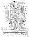
図2および図3に示すように、トルクコンバータ20は、相互に溶接されたフロントカバー34およびリヤカバー35と、リヤカバー35の内側に固定された複数のポンプ羽根20fとを有し、エンジン12のクランク軸12aと動力伝達可能に連結され、軸心RC回りに回転するように配設されたポンプ翼車(入力部材)20pと、リヤカバー35に対向し、変速機入力軸30に動力伝達可能に連結されたタービン翼車(出力部材)20tとを備えている。トルクコンバータ20は、後述する制御油室20d内にロックアップ係合圧PSLUが供給されることによってポンプ翼車20pとタービン翼車20tとの間を直結するロックアップクラッチ(多板式ロックアップクラッチ)32を備えている。このように、トルクコンバータ20は、エンジン12と自動変速機22との間の動力伝達経路に設けられた、ロックアップクラッチ32付車両用流体式伝動装置として機能している。また、動力伝達装置16には、ポンプ翼車20pに動力伝達可能に連結された機械式のオイルポンプ33が備えられている。オイルポンプ33は、エンジン12によって回転駆動されることにより、自動変速機22を変速制御したり、ロックアップクラッチ32を係合したり、動力伝達装置16の動力伝達経路の各部に潤滑油を供給したりする為の油圧を発生する(吐出する)。 As shown in FIGS. 2 and 3, the torque converter 20 includes a front cover 34 and a rear cover 35 welded to each other, and a plurality of pump blades 20 f fixed to the inside of the rear cover 35. A pump impeller (input member) 20p, which is connected to the shaft 12a so as to be able to transmit power and is arranged so as to rotate about the axis RC, and the rear cover 35, is connected to the transmission input shaft 30 so as to be able to transmit power. And a turbine impeller (output member) 20t. The torque converter 20, lock-up clutch (multi-plate lock-up clutch for directly connecting the pump impeller 20p and the turbine impeller 20t by the lock-up engagement pressure P SLU is supplied to the control oil chamber 20d to be described later ) 32. In this manner, the torque converter 20 functions as a vehicle fluid transmission device with a lock-up clutch 32 provided in a power transmission path between the engine 12 and the automatic transmission 22. The power transmission device 16 is provided with a mechanical oil pump 33 connected to the pump impeller 20p so as to be able to transmit power. The oil pump 33 is rotationally driven by the engine 12 to control the shift of the automatic transmission 22, engage the lockup clutch 32, and supply lubricating oil to each part of the power transmission path of the power transmission device 16. Generate hydraulic pressure to discharge (discharge).

ロックアップクラッチ32は、油圧式多板摩擦クラッチ(湿式多板クラッチ)であり、そのロックアップクラッチ32には、図3に示すように、ポンプ翼車20pと一体的に連結されたフロントカバー34に溶接によって固定された第1環状部材36と、第1環状部材36の外周に形成された外周スプライン歯36aに軸心RC回りに相対回転不能且つ軸心RC方向の移動可能に係合された複数枚(本実施例では3枚)の環状の第1摩擦板(摩擦材)38と、トルクコンバータ20内に設けられたダンパ装置40を介して変速機入力軸30およびタービン翼車20tに動力伝達可能に連結された第2環状部材42と、第2環状部材42の内周に形成された内周スプライン歯42aに軸心RC回りに相対回転不能且つ軸心RC方向の移動可能に係合され且つ複数の第1摩擦板38との間に配設された複数枚(本実施例では2枚)の環状の第2摩擦板(摩擦材)44と、フロントカバー34の内周部34aに固定され変速機入力軸30のフロントカバー34側の端部を軸心RC回りに回転可能に支持するハブ部材46に、軸心RC方向の移動可能に支持され、フロントカバー34に対向する環状の押圧部材(ピストン)48と、ハブ部材46に位置固定で支持され、押圧部材48のフロントカバー34側とは反対側に押圧部材48に対向するように配設された環状の固定部材50と、押圧部材48を軸心RC方向において固定部材50側に付勢するすなわち押圧部材48を軸心RC方向において第1摩擦板38および第2摩擦板44から離間させる方向に付勢するリターンスプリング52と、が備えられている。   The lock-up clutch 32 is a hydraulic multi-plate friction clutch (wet multi-plate clutch). As shown in FIG. 3, the lock-up clutch 32 has a front cover 34 integrally connected to the pump impeller 20p. The first annular member 36 fixed by welding to the outer peripheral spline teeth 36a formed on the outer periphery of the first annular member 36 are engaged with each other so as not to rotate relative to the axis RC and to move in the direction of the axis RC. Power is transmitted to the transmission input shaft 30 and the turbine impeller 20t via a plurality of (three in this embodiment) annular first friction plates (friction materials) 38 and a damper device 40 provided in the torque converter 20. The second annular member 42 connected so as to be able to transmit and the inner peripheral spline teeth 42a formed on the inner periphery of the second annular member 42 are relatively unrotatable around the axis RC and movable in the direction of the axis RC. And a plurality of (two in this embodiment) annular second friction plates (friction materials) 44 disposed between the first friction plates 38 and the inner periphery 34a of the front cover 34. Is mounted on a hub member 46 that is fixed to the end of the transmission input shaft 30 on the side of the front cover 34 so as to be rotatable about the axis RC, and is supported so as to be movable in the direction of the axis RC. A pressing member (piston) 48, and an annular fixing member 50 that is supported by the hub member 46 at a fixed position and is disposed on the opposite side of the pressing member 48 from the front cover 34 side so as to face the pressing member 48. The return spring 5 urges the pressing member 48 toward the fixed member 50 in the axial center RC direction, that is, urges the pressing member 48 in the direction separating the first friction plate 38 and the second friction plate 44 in the axial center RC direction. And, it is provided.

トルクコンバータ20には、図3に示すように、フロントカバー34およびリヤカバー35内に設けられ、オイルポンプ33から出力された作動油が供給される作動油供給ポート20aおよび作動油供給ポート20aから供給された作動油を流出させる作動油流出ポート20bを有する主油室(トルクコンバータ油室)20cが形成されている。また、トルクコンバータ20の主油室20c内には、ロックアップクラッチ32と、ロックアップクラッチ32を係合させるためのすなわちロックアップクラッチ32の第1摩擦材38および第2摩擦材44を押圧する押圧部材48をフロントカバー34側へ付勢するための例えばロックアップ係合圧PSLUが供給される制御油室20dと、ロックアップクラッチ32を解放させるためのすなわち押圧部材48をフロントカバー34側とは反対側へ付勢するための後述する例えば第2ライン油圧Psecが供給されるフロント側油室20eと、フロント側油室20eと連通しフロント側油室20eからの作動油で満たされてその作動油を作動油流出ポート20bから流出させるリヤ側油室20gとが設けられている。なお、上記制御油室20dは押圧部材48と固定部材50との間に形成された油密な空間であり、上記フロント側油室20eは押圧部材48とフロントカバー34との間に形成された空間であり、上記リヤ側油室20gは主油室20cにおいて制御油室20dおよびフロント側油室20eを除く空間である。 As shown in FIG. 3, the torque converter 20 is provided in the front cover 34 and the rear cover 35, and is supplied from the hydraulic oil supply port 20a and the hydraulic oil supply port 20a to which the hydraulic oil output from the oil pump 33 is supplied. A main oil chamber (torque converter oil chamber) 20c having a hydraulic oil outlet port 20b through which the hydraulic fluid flows out is formed. Further, the lock-up clutch 32 and the first friction material 38 and the second friction material 44 of the lock-up clutch 32 for pressing the lock-up clutch 32 are pressed into the main oil chamber 20c of the torque converter 20. a control oil chamber 20d, for example lock-up engagement pressure P SLU for biasing the pressing member 48 to the front cover 34 side is supplied, i.e. the front cover 34 side pressing member 48 for disengaging the lock-up clutch 32 For example, a front-side oil chamber 20e to which a second line oil pressure Psec, which will be described later for urging to the opposite side, is supplied, and the front-side oil chamber 20e communicates with the hydraulic oil from the front-side oil chamber 20e. A rear-side oil chamber 20g through which the hydraulic oil flows out from the hydraulic oil outlet port 20b is provided. The control oil chamber 20d is an oil-tight space formed between the pressing member 48 and the fixing member 50, and the front-side oil chamber 20e is formed between the pressing member 48 and the front cover 34. The rear oil chamber 20g is a space in the main oil chamber 20c excluding the control oil chamber 20d and the front oil chamber 20e.

トルクコンバータ20では、図3に示すように、例えば、制御油室20dに供給される油圧すなわちロックアップオン圧PLupON(kPa)が比較的大きく(フロント側油室20eの油圧すなわちトルクコンバータイン圧PTCin(kPa)が比較的小さく)なることにより押圧部材48が付勢されて一点鎖線に示すようにフロントカバー34側に移動させられると、押圧部材48によって第1摩擦板38および第2摩擦板44を押圧して第1環状部材36に連結されたポンプ翼車20pと第2環状部材42に連結されたタービン翼車20tとが一体回転する。すなわち、トルクコンバータ20では、ロックアップクラッチ32が係合すると、ポンプ翼車20pとタービン翼車20tとが直結する。また、例えば、制御油室20dのロックアップオン圧PLupON(kPa)が比較的小さく(フロント側油室20eのトルクコンバータイン圧PTCin(kPa)が比較的大きく)なることにより押圧部材48が実線に示すように第1摩擦板38から離間した位置に移動させられると、第1環状部材36に連結されたポンプ翼車20pと第2環状部材42に連結されたタービン翼車20tとが相対回転する。すなわち、トルクコンバータ20では、ロックアップクラッチ32が解放すると、ポンプ翼車20pとタービン翼車20tとが解放する。 In the torque converter 20, as shown in FIG. 3, for example, the hydraulic pressure supplied to the control oil chamber 20d, that is, the lock-up on-pressure P LUPON (kPa) is relatively large (the hydraulic pressure in the front-side oil chamber 20e, that is, the torque converter in-pressure). When P TCin (kPa) is relatively small), the pressing member 48 is urged and moved to the front cover 34 side as indicated by the alternate long and short dash line, so that the pressing member 48 causes the first friction plate 38 and the second friction plate 38 to move. The pump impeller 20p connected to the first annular member 36 by pressing the plate 44 and the turbine impeller 20t connected to the second annular member 42 rotate integrally. That is, in the torque converter 20, when the lockup clutch 32 is engaged, the pump impeller 20p and the turbine impeller 20t are directly connected. Further, for example, when the lock-up on pressure P LupON (kPa) in the control oil chamber 20d is relatively small (the torque converter in pressure P TCin (kPa) in the front oil chamber 20e is relatively large), the pressing member 48 is When moved to a position away from the first friction plate 38 as indicated by a solid line, the pump impeller 20p connected to the first annular member 36 and the turbine impeller 20t connected to the second annular member 42 are relatively Rotate. That is, in the torque converter 20, when the lockup clutch 32 is released, the pump impeller 20p and the turbine impeller 20t are released.

ロックアップクラッチ32は、制御油室20d内のロックアップオン圧PLupON(kPa)と、フロント側油室20e内のトルクコンバータイン圧PTCin(kPa)および作動油流出ポート20bから出力されるトルクコンバータアウト圧PTCout(kPa)の平均値((PTCin+PTCout)/2)との差圧すなわちロックアップ差圧ΔP(=PLupON−(PTCin+PTCout)/2)に基づいて、伝達トルクが制御される。なお、上記したロックアップ差圧(係合圧)ΔP=PLupON−(PTCin+PTCout)/2の式は、予め実験等によって決定された実験式である。また、上記式において、トルクコンバータイン圧PTCinとトルクコンバータアウト圧PTCoutは、エンジン回転数Ne(rpm)、タービン回転数Nt(rpm)、それらの差回転(エンジン回転数−タービン回転数)ΔN(rpm)、第2ライン油圧Psec(kPa)、ATF油温Toil(℃)、エンジントルクTe(Nm)等により変化する。なお、上記トルクコンバータアウト圧PTCoutは、エンジン回転数Ne、タービン回転数Nt、ATF油温Toil等が変化してトルクコンバータ20のリヤ側油室20g内の遠心油圧が変化することによって、変化する。 The lockup clutch 32 includes a lockup on pressure P LUPON (kPa) in the control oil chamber 20d, a torque converter in pressure P TCin (kPa) in the front oil chamber 20e, and a torque output from the hydraulic oil outflow port 20b. Based on the differential pressure from the average value ((P TCin + P TCout ) / 2) of the converter out pressure P TCout (kPa), that is, the lockup differential pressure ΔP (= P LupON − (P TCin + P TCout ) / 2) Torque is controlled. Note that the above-described equation of lockup differential pressure (engagement pressure) ΔP = P LUPON− (P TCin + P TCout ) / 2 is an empirical formula determined in advance through experiments or the like. In the above formula, the torque converter in pressure P TCin and the torque converter out pressure P TCout are the engine speed Ne (rpm), the turbine speed Nt (rpm), and their differential speed (engine speed-turbine speed). It varies depending on ΔN (rpm), second line oil pressure Psec (kPa), ATF oil temperature Toil (° C.), engine torque Te (Nm), and the like. The torque converter out pressure P TCout is changed by changing the centrifugal oil pressure in the rear oil chamber 20g of the torque converter 20 by changing the engine speed Ne, the turbine speed Nt, the ATF oil temperature Toil, and the like. To do.

ロックアップクラッチ32は、電子制御装置(制御装置)56によって油圧制御回路54を介してロックアップ差圧ΔPが制御されることで、例えば、ロックアップ差圧ΔPが負とされてロックアップクラッチ32が解放される所謂ロックアップ解放状態(ロックアップオフ)と、ロックアップ差圧ΔPが零以上とされてロックアップクラッチ32が滑りを伴って半係合される所謂ロックアップスリップ状態(スリップ状態)と、ロックアップ差圧ΔPが最大値とされてロックアップクラッチ32が完全係合される所謂ロックアップ状態(ロックアップオン)とのうちの何れかの作動状態に切り替えられる。なお、トルクコンバータ20は、ロックアップクラッチ32がロックアップ状態、ロックアップスリップ状態、ロックアップ解放状態であっても、フロント側油室20eとリヤ側油室20gとが同室すなわちフロント側油室20eとリヤ側油室20gとが常時相互に連通しており、作動油供給ポート20aからリヤ側油室20gへ向かう作動油によってロックアップクラッチ32が常時冷却される。また、トルクコンバータ20では、フロント側油室20eとリヤ側油室20gとが常時相互に連通しているフロント側油室20eおよびリヤ側油室20gの油室内において、ロックアップクラッチ32とポンプ翼車20pおよびタービン翼車20tとが同油室内に格納されている。   The lockup clutch 32 is controlled by the electronic control device (control device) 56 via the hydraulic pressure control circuit 54 so that, for example, the lockup differential pressure ΔP is negative and the lockup clutch 32 is negative. In a so-called lock-up released state (lock-up off) and a so-called lock-up slip state (slip state) in which the lock-up differential pressure ΔP is set to zero or more and the lock-up clutch 32 is half-engaged with slip. And a so-called lock-up state (lock-up on) in which the lock-up differential pressure ΔP is set to the maximum value and the lock-up clutch 32 is completely engaged. In the torque converter 20, even if the lockup clutch 32 is in the lockup state, the lockup slip state, and the lockup release state, the front side oil chamber 20e and the rear side oil chamber 20g are in the same chamber, that is, the front side oil chamber 20e. And the rear side oil chamber 20g are always in communication with each other, and the lockup clutch 32 is always cooled by the hydraulic oil from the hydraulic oil supply port 20a toward the rear side oil chamber 20g. Further, in the torque converter 20, the lock-up clutch 32 and the pump blade are provided in the oil chambers of the front oil chamber 20e and the rear oil chamber 20g in which the front oil chamber 20e and the rear oil chamber 20g are always in communication with each other. A vehicle 20p and a turbine impeller 20t are stored in the oil chamber.

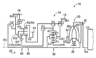
自動変速機22は、エンジン12から駆動輪14までの動力伝達経路の一部を構成し、複数の油圧式摩擦係合装置(第1クラッチC1〜第4クラッチC4、第1ブレーキB1、第2ブレーキB2)およびワンウェイクラッチF1が選択的に係合又は解放されることによりギヤ比(変速比)が異なる複数のギヤ段(変速段)が形成される有段式の自動変速機として機能する遊星歯車式多段変速機である。例えば、車両によく用いられる所謂クラッチツゥクラッチ変速を行う有段変速機である。自動変速機22は、ダブルピニオン型の第1遊星歯車装置58と、ラビニヨ型に構成されているシングルピニオン型の第2遊星歯車装置60およびダブルピニオン型の第3遊星歯車装置62とを同軸線上(軸心RC上)に有し、変速機入力軸30の回転を変速して変速機出力ギヤ24から出力する。   The automatic transmission 22 constitutes a part of a power transmission path from the engine 12 to the drive wheel 14 and includes a plurality of hydraulic friction engagement devices (first clutch C1 to fourth clutch C4, first brake B1, second brake). A planet that functions as a stepped automatic transmission in which a plurality of gear stages (gear stages) having different gear ratios (gear ratios) are formed by selectively engaging or releasing the brake B2) and the one-way clutch F1. This is a gear type multi-stage transmission. For example, it is a stepped transmission that performs a so-called clutch-to-clutch shift often used in vehicles. The automatic transmission 22 includes a double pinion type first planetary gear unit 58, a single pinion type second planetary gear unit 60 and a double pinion type third planetary gear unit 62 configured in Ravigneaux type on a coaxial line. (On the shaft center RC), the rotation of the transmission input shaft 30 is shifted and output from the transmission output gear 24.

第1遊星歯車装置58は、外歯歯車である第1サンギヤS1と、第1サンギヤS1と同心円上に配置される内歯歯車である第1リングギヤR1と、第1サンギヤS1および第1リングギヤR1と噛み合う、一対の歯車対からなる第1ピニオンギヤP1と、その第1ピニオンギヤP1を自転および公転可能に支持する第1キャリヤCA1とを有している。   The first planetary gear unit 58 includes a first sun gear S1 that is an external gear, a first ring gear R1 that is an internal gear disposed concentrically with the first sun gear S1, a first sun gear S1, and a first ring gear R1. And a first carrier CA1 that supports the first pinion gear P1 so as to be able to rotate and revolve.

第2遊星歯車装置60は、外歯歯車である第2サンギヤS2と、第2サンギヤS2と同心円上に配置される内歯歯車である第2リングギヤR2と、第2サンギヤS2および第2リングギヤR2と噛み合う第2ピニオンギヤP2と、その第2ピニオンギヤP2を自転および公転可能に支持する第2キャリヤCA2とを有している。   The second planetary gear device 60 includes a second sun gear S2 that is an external gear, a second ring gear R2 that is an internal gear arranged concentrically with the second sun gear S2, a second sun gear S2, and a second ring gear R2. And a second carrier CA2 that supports the second pinion gear P2 so as to be capable of rotating and revolving.

第3遊星歯車装置62は、外歯歯車である第3サンギヤS3と、第3サンギヤS3と同心円上に配置される内歯歯車である第3リングギヤR3と、その第3サンギヤS3および第3リングギヤR3と噛み合う、一対の歯車対からなる第3ピニオンギヤP3と、その第3ピニオンギヤP3を自転および公転可能に支持する第3キャリヤCA3とを有している。   The third planetary gear unit 62 includes a third sun gear S3 that is an external gear, a third ring gear R3 that is an internal gear disposed concentrically with the third sun gear S3, and the third sun gear S3 and the third ring gear. It has a third pinion gear P3 made up of a pair of gears that meshes with R3, and a third carrier CA3 that supports the third pinion gear P3 so that it can rotate and revolve.

上記第1クラッチC1,第2クラッチC2,第3クラッチC3,第4クラッチC4、および第1ブレーキB1,第2ブレーキB2(以下、特に区別しない場合は単に油圧式摩擦係合装置或いは係合要素という)は、油圧アクチュエータにより押圧される湿式多板型のクラッチやブレーキ、油圧アクチュエータによって引き締められるバンドブレーキなどにより構成される。   The first clutch C1, the second clutch C2, the third clutch C3, the fourth clutch C4, and the first brake B1, the second brake B2 (hereinafter, unless otherwise specified, simply a hydraulic friction engagement device or engagement element) Is composed of a wet multi-plate clutch and brake pressed by a hydraulic actuator, a band brake tightened by a hydraulic actuator, and the like.

これら油圧式摩擦係合装置の係合と解放とが制御されることで、図4の係合作動表に示すように、運転者のアクセル操作や車速V等に応じて前進8段、後進1段の各ギヤ段が形成される。図4の「1st」-「8th」は前進ギヤ段としての第1変速段−第8速変速段を意味し、「Rev」は後進ギヤ段としての後進変速段を意味しており、各変速段に対応する自動変速機22のギヤ比γ(=変速機入力軸回転速度Nin/変速機出力ギヤ回転速度Nout)は、第1遊星歯車装置58、第2遊星歯車装置60、及び第3遊星歯車装置62の各歯車比(=サンギヤの歯数/リングギヤの歯数)によって適宜定められる。   By controlling the engagement and disengagement of these hydraulic friction engagement devices, as shown in the engagement operation table of FIG. 4, the forward 8 stages and the reverse 1 are made according to the accelerator operation of the driver, the vehicle speed V, and the like. Each gear stage is formed. In FIG. 4, “1st” to “8th” means the first shift speed to the eighth shift speed as the forward gear, and “Rev” means the reverse speed as the reverse gear. The gear ratio γ (= transmission input shaft rotational speed Nin / transmission output gear rotational speed Nout) of the automatic transmission 22 corresponding to the stage is determined by the first planetary gear unit 58, the second planetary gear unit 60, and the third planetary unit. Each gear ratio of the gear device 62 (= the number of teeth of the sun gear / the number of teeth of the ring gear) is appropriately determined.

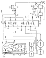
図5に示すように、油圧制御回路54には、ロックアップコントロールバルブ64と、オイルポンプ33から発生する油圧を元圧としてリリーフ形の第1ライン圧調圧弁67により調圧された第1ライン油圧PLを、ロックアップ係合圧PSLUに調圧するリニアソレノイドバルブSLUと、第1ライン油圧PLを元圧としてモジュレータ油圧PMODを一定値に調圧するモジュレータバルブ66とが備えられている。上記油圧制御回路54には、前記油圧式摩擦係合装置の図示しない各油圧アクチュエータの作動を制御するリニアソレノイドバルブSL1〜SL6(図1参照)が備えられている。なお、図5では、上記リニアソレノイドバルブSLUの元圧として第1ライン圧PLが用いられていたが、その第1ライン圧PLに替えてモジュレータ油圧PMODが用いられていても良い。 As shown in FIG. 5, the hydraulic control circuit 54 includes a first line regulated by a lock-up control valve 64 and a relief-type first line pressure regulating valve 67 using the hydraulic pressure generated from the oil pump 33 as a source pressure. A linear solenoid valve SLU that regulates the hydraulic pressure PL to the lock-up engagement pressure P SLU and a modulator valve 66 that regulates the modulator hydraulic pressure P MOD to a constant value using the first line hydraulic pressure PL as a source pressure are provided. The hydraulic control circuit 54 includes linear solenoid valves SL1 to SL6 (see FIG. 1) that control the operation of each hydraulic actuator (not shown) of the hydraulic friction engagement device. In FIG. 5, the first line pressure PL is used as the original pressure of the linear solenoid valve SLU. However, the modulator hydraulic pressure P MOD may be used instead of the first line pressure PL.

また、図5に示すように、ロックアップコントロールバルブ64は、ロックアップ係合圧PSLUが所定値を超えるとOFF位置からON位置へ切り換えられる型式の2位置切換弁であって、ON位置では、第1油路L1を閉路し、第2油路L2を第3油路L3へ接続し、第1油路L1を排出油路EXへ接続し、第4油路L4をクーラー68へ接続し、且つ第5油路L5を第6油路L6へ接続する。上記第1油路L1は、トルクコンバータ20の作動油流出ポート20bから出力されたトルクコンバータアウト圧PTCoutが導かれる油路である。上記第2油路L2は、リニアソレノイドバルブSLUによって調圧されたロックアップ係合圧PSLUが導かれる油路である。上記第3油路L3は、トルクコンバータ20の制御油室20dに供給されるロックアップオン圧PLupONが導かれる油路である。上記第4油路L4は、第1ライン圧調圧弁67からリリーフされた油圧を元圧として第2ライン圧調圧弁69により調圧された第2ライン油圧Psecが導かれる油路である。上記第5油路L5は、モジュレータバルブ66によって一定値に調圧されたモジュレータ油圧PMODが導かれる油路である。上記第6油路L6は、トルクコンバータ20のフロント側油室20eに供給されるトルクコンバータイン圧PTCinが導かれる油路である。 As shown in FIG. 5, the lock-up control valve 64 is a type of two-position switching valve that is switched from the OFF position to the ON position when the lock-up engagement pressure PSLU exceeds a predetermined value. The first oil passage L1 is closed, the second oil passage L2 is connected to the third oil passage L3, the first oil passage L1 is connected to the discharge oil passage EX, and the fourth oil passage L4 is connected to the cooler 68. And, the fifth oil passage L5 is connected to the sixth oil passage L6. The first oil passage L1 is an oil passage through which the torque converter out pressure P TCout output from the hydraulic oil outflow port 20b of the torque converter 20 is guided. The second oil passage L2 is an oil passage through which a lockup engagement pressure PSLU adjusted by the linear solenoid valve SLU is guided. The third oil passage L3 is an oil passage through which a lock-up ON pressure P LUPON supplied to the control oil chamber 20d of the torque converter 20 is guided. The fourth oil passage L4 is an oil passage through which the second line oil pressure Psec adjusted by the second line pressure adjusting valve 69 is guided using the oil pressure relieved from the first line pressure adjusting valve 67 as a base pressure. The fifth oil passage L5 is an oil passage through which the modulator hydraulic pressure P MOD adjusted to a constant value by the modulator valve 66 is guided. The sixth oil passage L6 is an oil passage through which the torque converter in-pressure PTCin supplied to the front oil chamber 20e of the torque converter 20 is guided.

また、ロックアップコントロールバルブ64は、図5に示すように、OFF位置では、第1油路L1を第3油路L3へ接続し、第2油路L2を閉路し、第1油路L1をクーラー68へ接続し、第4油路L4を第6油路L6へ接続し、且つ第5油路L5を閉路する。ロックアップコントロールバルブ64は、スプール弁子をOFF位置側へ付勢するスプリング64aと、スプール弁子をON位置側へ付勢するためにロックアップ係合圧PSLUを受け入れる油室64bとを備えている。ロックアップコントロールバルブ64では、ロックアップ係合圧PSLUが比較的小さく設定された所定値より小さい場合には、スプリング64aの付勢力によってスプール弁子がOFF位置に保持される。また、ロックアップコントロールバルブ64では、ロックアップ係合圧PSLUが前記所定値より大きい場合には、スプリング64aの付勢力に抗してスプール弁子がON位置に保持される。なお、図5のロックアップコントロールバルブ64では、実線はスプール弁子がON位置であるときの流路を示し、破線はスプール弁子がOFF位置であるときの流路を示している。 As shown in FIG. 5, the lock-up control valve 64 connects the first oil passage L1 to the third oil passage L3, closes the second oil passage L2, and closes the first oil passage L1 in the OFF position. The cooler 68 is connected, the fourth oil passage L4 is connected to the sixth oil passage L6, and the fifth oil passage L5 is closed. Lock-up control valve 64 comprises a spring 64a for biasing the spool to the OFF position side, an oil chamber 64b that accepts a lock-up engagement pressure P SLU for biasing the spool to the ON position side ing. In the lockup control valve 64, when the lockup engagement pressure PSLU is smaller than a predetermined value set relatively small, the spool valve element is held at the OFF position by the biasing force of the spring 64a. In the lockup control valve 64, when the lockup engagement pressure PSLU is larger than the predetermined value, the spool valve element is held at the ON position against the urging force of the spring 64a. In the lockup control valve 64 of FIG. 5, the solid line indicates the flow path when the spool valve element is in the ON position, and the broken line indicates the flow path when the spool valve element is in the OFF position.

上記のように構成された油圧制御回路54により、ロックアップコントロールバルブ64からトルクコンバータ20における制御油室20dおよびフロント側油室20eへ供給される油圧が切換えられることで、ロックアップクラッチ32の作動状態が切り替えられる。先ず、ロックアップクラッチ32がスリップ状態乃至ロックアップオンとされた場合を説明する。ロックアップコントロールバルブ64において、電子制御装置56から出力される指令信号によって前記所定値より大きくされたロックアップ係合圧PSLUが供給されると、ロックアップコントロールバルブ64がON位置に切り替えられ、ロックアップ係合圧PSLUがトルクコンバータ20の制御油室20dへ供給されると共に、ロックアップコントロールバルブ64に供給されたモジュレータ油圧PMODがトルクコンバータ20のフロント側油室20eへ供給される。すなわち、ロックアップ係合圧PSLUがロックアップオン圧PLupONとして制御油室20dに供給され、モジュレータ油圧PMODがトルクコンバータイン圧PTCinとしてフロント側油室20eに供給される。なお、ロックアップコントロールバルブ64がON位置に切り替えられると、ロックアップオン圧PLupONと、トルクコンバータイン圧PTCinと、トルクコンバータアウト圧PTCoutとの大きさの関係は、ロックアップオン圧PLupON>トルクコンバータイン圧PTCin>トルクコンバータアウト圧PTCoutとなる。これによって、トルクコンバータ20の制御油室20dのロックアップオン圧(係合圧)PLupONがリニアソレノイドバルブSLUにより調圧されることにより、ロックアップ差圧(PLupON−(PTCin+PTCout)/2)ΔPが調圧されて、ロックアップクラッチ32の作動状態がスリップ状態乃至ロックアップオン(完全係合)の範囲で切り替えられる。 The hydraulic pressure supplied from the lockup control valve 64 to the control oil chamber 20d and the front oil chamber 20e in the torque converter 20 is switched by the hydraulic control circuit 54 configured as described above, whereby the lockup clutch 32 operates. The state is switched. First, the case where the lockup clutch 32 is in the slip state or the lockup on will be described. In the lockup control valve 64, when the lockup engagement pressure PSLU that is larger than the predetermined value by the command signal output from the electronic control device 56 is supplied, the lockup control valve 64 is switched to the ON position, The lockup engagement pressure P SLU is supplied to the control oil chamber 20 d of the torque converter 20, and the modulator hydraulic pressure P MOD supplied to the lockup control valve 64 is supplied to the front oil chamber 20 e of the torque converter 20. That is, the lock-up engagement pressure P SLU is supplied to the control oil chamber 20d as a lock-up on pressure P LupON, modulator pressure P MOD is supplied to the front side oil chamber 20e as a torque converter in pressure P TCIN. When the lockup control valve 64 is switched to the ON position, the relationship among the lockup on pressure P LupON , the torque converter in pressure P TCin, and the torque converter out pressure P TCout is expressed as follows. LUPON > torque converter in pressure P TCin > torque converter out pressure P TCout . As a result, the lockup ON pressure (engagement pressure) P LupON of the control oil chamber 20d of the torque converter 20 is regulated by the linear solenoid valve SLU, so that the lockup differential pressure (P LupON − (P TCin + P TCout )). / 2) ΔP is adjusted, and the operating state of the lock-up clutch 32 is switched in the range from the slip state to the lock-up on (complete engagement).

次に、ロックアップクラッチ32がロックアップオフとされた場合を説明する。ロックアップコントロールバルブ64において、ロックアップ係合圧PSLUが前記所定値より小さい場合には、ロックアップコントロールバルブ64がスプリング64aの付勢力によりOFF位置に切り替えられ、トルクコンバータ20の作動油流出ポート20bから出力されたトルクコンバータアウト圧PTCoutがトルクコンバータ20の制御油室20dへ供給されると共に、第2ライン油圧Psecがトルクコンバータ20のフロント側油室20eへ供給される。すなわち、トルクコンバータアウト圧PTCoutがロックアップオン圧PLupONとして制御油室20dに供給され、第2ライン油圧Psecがトルクコンバータイン圧PTCinとしてフロント側油室20eに供給される。なお、ロックアップコントロールバルブ64がOFF位置に切り替えられると、上記ロックアップオン圧PLupONと、トルクコンバータイン圧PTCinと、トルクコンバータアウト圧PTCoutとの大きさの関係は、トルクコンバータイン圧PTCin>トルクコンバータアウト圧PTCout>ロックアップオン圧PLupONとなる。これによって、ロックアップクラッチ32の作動状態がロックアップオフに切り替えられる。 Next, a case where the lockup clutch 32 is locked off will be described. In the lock-up control valve 64, when the lock-up engagement pressure PSLU is smaller than the predetermined value, the lock-up control valve 64 is switched to the OFF position by the biasing force of the spring 64a, and the hydraulic oil outflow port of the torque converter 20 The torque converter out pressure P TCout output from 20b is supplied to the control oil chamber 20d of the torque converter 20, and the second line oil pressure Psec is supplied to the front oil chamber 20e of the torque converter 20. That is, the torque converter out pressure PTCout is supplied to the control oil chamber 20d as the lockup on pressure PLupON , and the second line oil pressure Psec is supplied to the front side oil chamber 20e as the torque converter in pressure PTCin . When the lock-up control valve 64 is switched to the OFF position, the relationship among the magnitudes of the lock-up on pressure P LupON , the torque converter in pressure P TCin, and the torque converter out pressure P TCout depends on the torque converter in pressure. P TCin > torque converter out pressure P TCout > lockup on pressure P LupON As a result, the operating state of the lockup clutch 32 is switched to lockup off.

図1に戻り、車両10は、例えばロックアップクラッチ32のロックアップ係合圧PSLUすなわちロックアップ差圧ΔPを制御するロックアップ制御と、自動変速機22の変速時の油圧式摩擦係合装置の係合圧を制御する変速制御等とを油圧制御回路54を介して実行する電子制御装置56を備えている。図1は、電子制御装置56の入出力系統を示す図であり、電子制御装置56による制御機能の要部を説明する機能ブロックである。電子制御装置56は、例えばCPU、RAM、ROM、入出力インターフェース等を備えた所謂マイクロコンピュータを含んで構成されており、CPUはRAMの一時記憶機能を利用しつつ予めROMに記憶されたプログラムに従って信号処理を行うことにより車両10の各制御を実行する。 Returning to Figure 1, the vehicle 10 includes, for example, a lock-up control for controlling the lock-up engagement pressure P SLU i.e. lockup differential pressure ΔP of the lockup clutch 32, hydraulic friction engagement device in the gear shifting of the automatic transmission 22 An electronic control unit 56 is provided for executing a shift control and the like for controlling the engagement pressure via the hydraulic control circuit 54. FIG. 1 is a diagram showing an input / output system of the electronic control unit 56, and is a functional block for explaining a main part of a control function by the electronic control unit 56. The electronic control unit 56 includes, for example, a so-called microcomputer having a CPU, a RAM, a ROM, an input / output interface, and the like. The CPU uses a temporary storage function of the RAM and follows a program stored in the ROM in advance. Each control of the vehicle 10 is executed by performing signal processing.

電子制御装置56には、車両10が備える各種センサにより検出される各種入力信号が供給されるようになっている。例えば、スロットル弁開度センサ70により検出されるスロットル弁開度θth(%)を表す信号、車速センサ72により検出される車速V(km/h)を表す信号、アクセル操作量センサ74により検出されるアクセルペダルの操作量であるアクセル開度θacc(%)を表す信号、第1油温センサ76により検出されるロックアップクラッチ32の下流の第1油温(油温)T1(℃)例えばトルクコンバータ20の作動油流出ポート20bから流出される作動油の第1油温T1(℃)を表す信号、第2油温センサ77により検出されるロックアップクラッチ32の上流の第2油温T2(℃)例えばトルクコンバータ20の作動油供給ポート20aに供給される作動油の第2油温T2(℃)を表す信号、エンジン回転センサ78により検出されるエンジン12のエンジン回転数Ne(rpm)を表す信号、タービン回転センサ80により検出されるトルクコンバータ20のタービン翼車20tのタービン回転数Nt(rpm)を表す信号等、が電子制御装置56に入力される。また、電子制御装置56からは、自動変速機22の変速に関する油圧制御の為の変速指示圧Satと、ロックアップクラッチ32の作動状態の切替制御のためのロックアップ指示圧Slu等とが、それぞれ出力される。なお、上記変速指示圧Satは、油圧式摩擦係合装置の図示しない各油圧アクチュエータへ供給される各油圧を調圧するリニアソレノイドバルブSL1〜SL6を駆動する為の指示信号であり、油圧制御回路54のリニアソレノイドバルブSL1〜SL6へ出力される。また、上記ロックアップ指示圧Sluは、ロックアップ係合圧PSLUを調圧するリニアソレノイドバルブSLUを駆動する為の指示信号であり、油圧制御回路54のリニアソレノイドバルブSLUへ出力される。 Various input signals detected by various sensors provided in the vehicle 10 are supplied to the electronic control unit 56. For example, a signal indicating the throttle valve opening θth (%) detected by the throttle valve opening sensor 70, a signal indicating the vehicle speed V (km / h) detected by the vehicle speed sensor 72, and the accelerator operation amount sensor 74 are detected. A signal representing the accelerator opening θacc (%), which is the amount of operation of the accelerator pedal, and a first oil temperature (oil temperature) T1 (° C.) downstream of the lockup clutch 32 detected by the first oil temperature sensor 76, for example torque A signal representing the first oil temperature T1 (° C.) of the hydraulic oil flowing out from the hydraulic oil outlet port 20b of the converter 20, the second oil temperature T2 upstream of the lockup clutch 32 detected by the second oil temperature sensor 77 ( ° C) For example, a signal representing the second oil temperature T2 (° C) of the hydraulic oil supplied to the hydraulic oil supply port 20a of the torque converter 20 is detected by the engine rotation sensor 78. A signal indicating the engine speed Ne (rpm) of the engine 12, a signal indicating the turbine speed Nt (rpm) of the turbine impeller 20 t of the torque converter 20 detected by the turbine rotation sensor 80, and the like are input to the electronic control unit 56. Is done. Further, the electronic control unit 56 receives a shift command pressure Sat for hydraulic control related to the shift of the automatic transmission 22, a lockup command pressure Slu for controlling the switching of the operation state of the lockup clutch 32, and the like. Is output. The shift command pressure Sat is a command signal for driving the linear solenoid valves SL1 to SL6 that regulate the hydraulic pressure supplied to the hydraulic actuators (not shown) of the hydraulic friction engagement device. Are output to the linear solenoid valves SL1 to SL6. Further, the lock-up command pressure Slu is a command signal for driving the linear solenoid valve SLU for pressurizing regulating the lockup engagement pressure P SLU, is output to the linear solenoid valve SLU of the hydraulic control circuit 54.

図1に示す電子制御装置56は、制御機能の要部として、ロックアップクラッチ制御部82と、摩擦材温度推定部84とを含んでいる。図1に示すロックアップクラッチ制御部82は、フレックスロックアップ制御実施判定部82aと、制御切替部82b等とを備えている。ロックアップクラッチ制御部82は、ロックアップクラッチ32のロックアップ差圧(PLupON−(PTCin+PTCout)/2)ΔPすなわちロックアップ係合圧PSLUのロックアップ指示圧Sluを制御するロックアップ制御を実行する。ロックアップクラッチ制御部82は、車速Vおよびスロットル弁開度θthを変数として、ロックアップオフ領域、スリップ作動領域、ロックアップオン領域を有する予め定められた関係(ロックアップ領域線図)を用いて実際の車速Vおよびスロットル弁開度θthに基づいて、ロックアップオフ領域、スリップ作動領域、ロックアップオン領域の何れの領域であるかを判断し、その判断した領域に対応する作動状態にロックアップクラッチ32の作動状態がなるように、指示信号であるロックアップ指示圧Sluを制御する。このロックアップ指示圧Sluに従って、判断した領域に対応する作動状態にロックアップクラッチ32の作動状態がなるように油圧制御回路54に設けられたリニアソレノイドバルブSLUが駆動(作動)させられる。例えば、ロックアップクラッチ制御部82では、前記ロックアップ領域線図で前記ロックアップオン領域であると判断されると、ロックアップクラッチ32を完全係合するようにロックアップクラッチ32のロックアップ係合圧PSLUのロックアップ指示圧Sluを制御する完全ロックアップ制御が実行される。また、ロックアップクラッチ制御部80では、前記ロックアップ領域線図で前記スリップ作動領域であると判断されると、ロックアップクラッチ32を完全係合させずにトルクコンバータ20においてポンプ翼車20pとタービン翼車20tとを予め設定された差回転ΔN(rpm)でロックアップクラッチ32がスリップするように、ロックアップクラッチ32のロックアップ係合圧PSLUのロックアップ指示圧Sluを制御するフレックスロックアップ制御が実行される。なお、上記差回転ΔNは、ポンプ翼車20pの回転数すなわちエンジン回転数Ne(rpm)と、タービン翼車20tの回転数すなわちタービン回転数Nt(rpm)との差回転である。 The electronic control unit 56 shown in FIG. 1 includes a lockup clutch control unit 82 and a friction material temperature estimation unit 84 as the main parts of the control function. The lockup clutch control unit 82 shown in FIG. 1 includes a flex lockup control execution determination unit 82a, a control switching unit 82b, and the like. The lock-up clutch control unit 82 controls the lock-up differential pressure (P LUPON- (P TCin + P TCout ) / 2) ΔP of the lock-up clutch 32, that is, the lock-up command pressure Slu for the lock-up engagement pressure P SLU. Execute control. The lock-up clutch control unit 82 uses a predetermined relationship (lock-up region diagram) having a lock-up off region, a slip operation region, and a lock-up on region with the vehicle speed V and the throttle valve opening θth as variables. Based on the actual vehicle speed V and the throttle valve opening θth, it is determined which region is a lock-up off region, a slip operation region, or a lock-up on region, and the operation state corresponding to the determined region is locked up. The lockup command pressure Slu, which is a command signal, is controlled so that the clutch 32 is in an operating state. In accordance with the lockup command pressure Slu, the linear solenoid valve SLU provided in the hydraulic control circuit 54 is driven (operated) so that the operation state of the lockup clutch 32 is brought into the operation state corresponding to the determined region. For example, when the lockup clutch control unit 82 determines that the lockup on region is in the lockup region diagram, the lockup clutch 32 is engaged so that the lockup clutch 32 is completely engaged. The complete lockup control for controlling the lockup command pressure Slu of the pressure P SLU is executed. Further, when the lockup clutch control unit 80 determines that the slip operation region is in the lockup region diagram, the torque converter 20 does not completely engage the lockup clutch 32 and the pump impeller 20p and the turbine are not engaged. Flex lock-up for controlling the lock-up command pressure Slu of the lock-up engagement pressure P SLU of the lock-up clutch 32 so that the lock-up clutch 32 slips with the impeller 20t at a preset differential rotation ΔN (rpm). Control is executed. The differential rotation ΔN is a differential rotation between the rotational speed of the pump impeller 20p, that is, the engine rotational speed Ne (rpm), and the rotational speed of the turbine impeller 20t, that is, the turbine rotational speed Nt (rpm).

フレックスロックアップ制御実施判定部82aは、ロックアップクラッチ制御部82でフレックスロックアップ制御が実施中であるか否かを判定する。例えば、フレックスロックアップ制御実施判定部82aは、実際の車速Vおよびスロットル弁開度θthが、前記ロックアップ領域線図において、前記スリップ作動領域である時に、フレックスロックアップ制御が実施中であると判定し、前記ロックアップオン領域または前記ロックアップオフ領域である時に、フレックスロックアップ制御が実施中でないと判定する。   The flex lockup control execution determination unit 82a determines whether the lockup clutch control unit 82 is executing flex lockup control. For example, the flex lockup control execution determination unit 82a determines that the flex lockup control is being performed when the actual vehicle speed V and the throttle valve opening θth are in the slip operation region in the lockup region diagram. And when it is in the lockup on region or the lockup off region, it is determined that flex lockup control is not being performed.

摩擦材温度推定部84は、発熱量推定部84aと、放熱量推定部84bと、記憶部84cとを備える。摩擦材温度推定部84は、フレックスロックアップ制御実施判定部82aでフレックスロックアップ制御が実施中であると判定されると、ロックアップクラッチ32の摩擦材の推定温度Tclすなわちロックアップクラッチ32の第1摩擦板38および第2摩擦板44の推定温度Tclを推定する。   The friction material temperature estimation unit 84 includes a heat generation amount estimation unit 84a, a heat release amount estimation unit 84b, and a storage unit 84c. When the flex lockup control execution determination unit 82a determines that the flex lockup control is being performed, the friction material temperature estimation unit 84 determines the estimated friction material temperature Tcl of the lockup clutch 32, that is, the lockup clutch 32 Estimated temperatures Tcl of the first friction plate 38 and the second friction plate 44 are estimated.

発熱ゲイン設定部84dを有する発熱量推定部84aは、フレックスロックアップ制御実施判定部82aでフレックスロックアップ制御が実施中であると判定されると、そのフレックスロックアップ制御によってロックアップクラッチ32の第1摩擦板38および第2摩擦板44で発熱する発熱量Qhを発熱ゲイン設定部84dで設定された発熱ゲインKheatを用いて推定する。   When the flex lockup control execution determination unit 82a determines that the flex lockup control is being performed, the heat generation amount estimation unit 84a having the heat generation gain setting unit 84d performs the first operation of the lockup clutch 32 by the flex lockup control. The heat generation amount Qh generated by the first friction plate 38 and the second friction plate 44 is estimated using the heat generation gain Kheat set by the heat generation gain setting unit 84d.

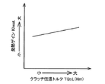
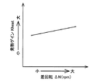
発熱ゲイン設定部84dは、フレックスロックアップ制御実施判定部82aでフレックスロックアップ制御が実施中であると判定されると、そのフレックスロックアップ制御実施判定部82aでフレックスロックアップ制御が実施中であると判定された時の、ロックアップクラッチ32におけるポンプ翼車20pとタービン翼車20tとの差回転ΔN、ロックアップクラッチ32に伝達されるクラッチ伝達トルクTQcL(Nm)等を用いて、例えば図6、図7に示すマップによって発熱ゲインKheatを設定する。例えば、発熱ゲイン設定部84dでは、フレックスロックアップ制御実施判定部82aでフレックスロックアップ制御が実施中であると判定された時のロックアップクラッチ32のクラッチ伝達トルクTQcLが大きい程、図6のマップに示すように、発熱ゲインKheatが大きくなるように設定される。また、発熱ゲイン設定部84dでは、フレックスロックアップ制御実施判定部82aでフレックスロックアップ制御が実施中であると判定された時のロックアップクラッチ32の差回転ΔNが大きい程、図7のマップに示すように、発熱ゲインKheatが大きくなるように設定される。なお、ロックアップクラッチ32のクラッチ伝達トルクTQcLは、下記式(1)により算出される。
TQcL=Te−c×Ne ・・・(1)
上記式(1)において、上記Teはエンジン12の出力トルクであり、予め求められているアクセル開度θaccおよびエンジン回転数NeからなるエンジントルクTeの関係マップから、実際のアクセル開度θaccおよび実際のエンジン回転数Neに基いて求められる。また、上記cは、トルクコンバータ20の容量係数に対応しており、例えば、電子制御装置56に予め記憶されているトルクコンバータ20の性能曲線により求められる。
When the flex lockup control execution determination unit 82a determines that the flex lockup control is being performed, the heat gain setting unit 84d is performing the flex lockup control by the flex lockup control execution determination unit 82a. Using the differential rotation ΔN between the pump impeller 20p and the turbine impeller 20t in the lockup clutch 32, the clutch transmission torque TQcL (Nm) transmitted to the lockup clutch 32, etc. The heat generation gain Kheat is set according to the map shown in FIG. For example, in the heat gain setting unit 84d, as the clutch transmission torque TQcL of the lockup clutch 32 when the flex lockup control execution determination unit 82a determines that the flex lockup control is being performed is larger, the map of FIG. As shown in FIG. 4, the heat generation gain Kheat is set to be large. Further, in the heat gain setting unit 84d, as the differential rotation ΔN of the lockup clutch 32 when the flex lockup control execution determination unit 82a determines that the flex lockup control is being performed is larger, the map of FIG. As shown, the heat generation gain Kheat is set to be large. The clutch transmission torque TQcL of the lockup clutch 32 is calculated by the following equation (1).
TQcL = Te−c × Ne 2 (1)
In the above formula (1), Te is the output torque of the engine 12, and the actual accelerator opening θacc and the actual accelerator opening Teacc are calculated from the relationship map of the engine opening Te obtained from the accelerator opening θacc and the engine speed Ne. It is obtained based on the engine speed Ne. In addition, c corresponds to the capacity coefficient of the torque converter 20 and is obtained, for example, from the performance curve of the torque converter 20 stored in advance in the electronic control unit 56.

発熱量推定部84aは、発熱ゲイン設定部84dで発熱ゲインKheatが設定されると、その設定された発熱ゲインKheatを用いてロックアップクラッチ32の第1摩擦板38および第2摩擦板44で発熱する発熱量Qhを推定する。すなわち、発熱量推定部84aは、発熱ゲイン設定部84dで発熱ゲインKheatが設定されると、下記式(2)を用いてロックアップクラッチ32の第1摩擦板38および第2摩擦板44で発熱する発熱量Qhを算出する。
Qh=Kheat×TQcL×ΔN ・・・(2)
When the heat generation gain Kheat is set by the heat generation gain setting unit 84d, the heat generation amount estimation unit 84a generates heat at the first friction plate 38 and the second friction plate 44 of the lockup clutch 32 using the set heat generation gain Kheat. The amount of generated heat Qh is estimated. That is, when the heat generation gain Kheat is set by the heat generation gain setting unit 84d, the heat generation amount estimation unit 84a generates heat at the first friction plate 38 and the second friction plate 44 of the lockup clutch 32 using the following equation (2). The calorific value Qh to be calculated is calculated.
Qh = Kheat × TQcL × ΔN (2)

なお、発熱量推定部84aでは、上述したように発熱ゲイン設定部84dで例えばロックアップクラッチ32のクラッチ伝達トルクTQcLが大きいほど発熱ゲインKheatが大きくなるように設定され、且つ、ロックアップクラッチ32の差回転ΔNが大きいほど発熱ゲインKheatが大きくなるように設定されるので、ロックアップクラッチ32のクラッチ伝達トルクTQcLが大きいほど、且つ、ロックアップクラッチ32の差回転ΔNが大きいほど、発熱量Qhが大きくなるように推定される。   In the heat generation amount estimation unit 84a, as described above, the heat generation gain setting unit 84d sets, for example, the heat generation gain Kheat to increase as the clutch transmission torque TQcL of the lockup clutch 32 increases, and the lockup clutch 32 Since the heat generation gain Kheat is set to increase as the differential rotation ΔN increases, the heat generation amount Qh increases as the clutch transmission torque TQcL of the lockup clutch 32 increases and the differential rotation ΔN of the lockup clutch 32 increases. It is estimated to be large.

放熱ゲイン設定部84eを有する放熱量推定部84bは、フレックスロックアップ制御実施判定部82aでフレックスロックアップ制御が実施中であると判定されると、そのフレックスロックアップ制御によってロックアップクラッチ32の第1摩擦板38および第2摩擦板44から放熱される放熱量Qcを、放熱ゲイン設定部84eで設定された放熱ゲインKcoolを用いて推定する。   When the flex lockup control execution determination unit 82a determines that the flex lockup control is being performed, the heat dissipation amount estimation unit 84b having the heat dissipation gain setting unit 84e performs the first operation of the lockup clutch 32 by the flex lockup control. The heat dissipation amount Qc radiated from the first friction plate 38 and the second friction plate 44 is estimated using the heat dissipation gain Kcool set by the heat dissipation gain setting unit 84e.

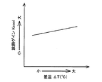
放熱ゲイン設定部84eは、フレックスロックアップ制御実施判定部82aでフレックスロックアップ制御が実施中であると判定されると、そのフレックスロックアップ制御実施判定部82aでフレックスロックアップ制御が実施中であると判定された時の、タービン回転数Nt(rpm)、記憶部84cに記憶されたロックアップクラッチ32の第1摩擦板38および第2摩擦板44の推定温度T0(℃)とロックアップクラッチ32の下流の第1油温T1(℃)との差温ΔT(℃)等を用いて、例えば図8、図9に示すマップによって放熱ゲインKcoolを設定する。例えば、放熱ゲイン設定部84eでは、フレックスロックアップ制御実施判定部82aでフレックスロックアップ制御が実施中であると判定された時のタービン回転数Nt(rpm)が高い程、図8のマップに示すように、放熱ゲインKcoolが大きくなるように設定される。また、放熱ゲイン設定部84eでは、フレックスロックアップ制御実施判定部82aでフレックスロックアップ制御が実施中であると判定された時の差温ΔT(℃)が大きい程、図9のマップに示すように、放熱ゲインKcoolが大きくなるように設定される。   When it is determined by the flex lockup control execution determination unit 82a that the flex lockup control is being performed, the heat dissipation gain setting unit 84e is performing flex lockup control by the flex lockup control execution determination unit 82a. And the estimated temperature T0 (° C.) of the first friction plate 38 and the second friction plate 44 of the lock-up clutch 32 stored in the storage unit 84c and the lock-up clutch 32. The heat dissipation gain Kcool is set using, for example, the maps shown in FIGS. 8 and 9 using the difference temperature ΔT (° C.) from the first oil temperature T1 (° C.) downstream of the first oil temperature. For example, in the heat dissipation gain setting unit 84e, the higher the turbine rotation speed Nt (rpm) when the flex lockup control execution determination unit 82a determines that the flex lockup control is being performed, the higher the value shown in the map of FIG. In this way, the heat radiation gain Kcool is set to be large. Further, in the heat radiation gain setting unit 84e, as the temperature difference ΔT (° C.) when the flex lockup control execution determination unit 82a determines that the flex lockup control is being performed is larger, the map of FIG. 9 shows. In addition, the heat radiation gain Kcool is set to be large.

放熱量推定部84bは、放熱ゲイン設定部84eで放熱ゲインKcoolが設定されると、その設定された放熱ゲインKcoolを用いてロックアップクラッチ32の第1摩擦板38および第2摩擦板44から放熱される放熱量Qcを推定する。すなわち、放熱量推定部84bは、放熱ゲイン設定部84eで放熱ゲインKcoolが設定されると、下記式(3)を用いてロックアップクラッチ32の第1摩擦板38および第2摩擦板44から放熱する放熱量Qcを算出する。
Qc=Kcool×((T0−T2)−A) ・・・(3)
なお、上記式(3)において、上記Aは、予め設定された定数である。
When the heat radiation gain setting unit 84e sets the heat radiation gain Kcool, the heat radiation amount estimation unit 84b radiates heat from the first friction plate 38 and the second friction plate 44 of the lockup clutch 32 using the set heat radiation gain Kcool. The amount of released heat Qc is estimated. That is, when the heat radiation gain setting unit 84e sets the heat radiation gain Kcool, the heat radiation amount estimation unit 84b radiates heat from the first friction plate 38 and the second friction plate 44 of the lockup clutch 32 using the following equation (3). The amount of heat release Qc to be calculated is calculated.
Qc = Kcool × ((T0−T2) −A) (3)
In the above formula (3), A is a preset constant.

なお、放熱量推定部84dでは、上述したように放熱ゲイン設定部84eで例えば差温ΔT(℃)が大きいほど放熱ゲインKcoolが大きくなるように設定され、且つ、タービン回転数Nt(rpm)が高いほど放熱ゲインKcoolが大きくなるように設定されるので、ロックアップクラッチ32の第1摩擦板38および第2摩擦板44の推定温度T0(℃)とロックアップクラッチ32の下流の第1油温T1(℃)との差温ΔT(℃)が大きいほど、且つ、トルクコンバータ20のタービン回転数Nt(rpm)が高いほど、放熱量Qcが大きくなるように推定される。   In the heat radiation amount estimation unit 84d, as described above, for example, the heat radiation gain setting unit 84e sets the heat radiation gain Kcool to increase as the temperature difference ΔT (° C.) increases, and the turbine rotational speed Nt (rpm) is set. The higher the heat dissipation gain Kcool is, the higher the value is. Therefore, the estimated temperature T0 (° C.) of the first friction plate 38 and the second friction plate 44 of the lockup clutch 32 and the first oil temperature downstream of the lockup clutch 32 are set. It is estimated that the heat radiation amount Qc increases as the temperature difference ΔT (° C.) from T1 (° C.) increases and as the turbine rotational speed Nt (rpm) of the torque converter 20 increases.

記憶部84cは、摩擦材温度推定部84でロックアップクラッチ32の第1摩擦板38および第2摩擦板44の推定温度Tcl(℃)が推定されると、その推定された推定温度Tcl(℃)を推定温度T0(℃)として記憶する。なお、記憶部84cでは、摩擦材温度推定部84でロックアップクラッチ32の第1摩擦板38および第2摩擦板44の推定温度Tcl(℃)が推定されていない場合には、初期値として例えば第1油温センサ76で検出される第1油温T1(℃)が推定温度T0(℃)として記憶される。   When the friction material temperature estimation unit 84 estimates the estimated temperature Tcl (° C.) of the first friction plate 38 and the second friction plate 44 of the lockup clutch 32, the storage unit 84c estimates the estimated temperature Tcl (° C. ) As the estimated temperature T0 (° C.). In the storage unit 84c, when the estimated temperature Tcl (° C.) of the first friction plate 38 and the second friction plate 44 of the lockup clutch 32 is not estimated by the friction material temperature estimation unit 84, for example, as an initial value, The first oil temperature T1 (° C.) detected by the first oil temperature sensor 76 is stored as the estimated temperature T0 (° C.).

摩擦材温度推定部84は、発熱量推定部84aでロックアップクラッチ32の第1摩擦板38および第2摩擦板44で発熱する発熱量Qhが推定され、且つ、放熱量推定部84bでロックアップクラッチ32の第1摩擦板38および第2摩擦板44から放熱する放熱量Qcが推定されると、その推定された発熱量Qhからロックアップクラッチ32の第1摩擦板38および第2摩擦板44の温度が上昇する上昇温度ΔTheat(℃)を算出し、その推定された放熱量Qcからロックアップクラッチ32の第1摩擦板38および第2摩擦板44の温度が下降する下降温度ΔTcool(℃)を算出して、記憶部84cに記憶された推定温度T0(℃)を基にしてロックアップクラッチ32の第1摩擦板38および第2摩擦板44の推定温度Tcl(℃)を推定する。すなわち、摩擦材温度推定部84では、発熱量推定部84aでロックアップクラッチ32の第1摩擦板38および第2摩擦板44で発熱する発熱量Qhが推定され、且つ、放熱量推定部84bでロックアップクラッチ32の第1摩擦板38および第2摩擦板44から放熱する放熱量Qcが推定されると、下記式(4)を用いてロックアップクラッチ32の第1摩擦板38および第2摩擦板44の推定温度Tcl(℃)を算出する。
Tcl=T0+((Qh/Ccl)−(Qc/Ccl)) ・・・(4)
なお、上記式(4)において、Cclは、ロックアップクラッチ32の第1摩擦板38および第2摩擦板44の熱容量である。また、上記(Qh/Ccl)は上昇温度ΔTheatに対応し、上記(Qc/Ccl)は下降温度ΔTcoolに対応する。
The friction material temperature estimation unit 84 estimates the heat generation amount Qh generated by the first friction plate 38 and the second friction plate 44 of the lockup clutch 32 by the heat generation amount estimation unit 84a, and locks up by the heat dissipation amount estimation unit 84b. When the heat release amount Qc radiated from the first friction plate 38 and the second friction plate 44 of the clutch 32 is estimated, the first friction plate 38 and the second friction plate 44 of the lockup clutch 32 are estimated from the estimated heat generation amount Qh. The rise temperature ΔTheat (° C.) at which the temperature of the first friction plate rises, and the fall temperature ΔTcool (° C.) at which the temperatures of the first friction plate 38 and the second friction plate 44 of the lockup clutch 32 fall from the estimated heat release amount Qc. And the estimated temperature Tc of the first friction plate 38 and the second friction plate 44 of the lockup clutch 32 based on the estimated temperature T0 (° C.) stored in the storage unit 84c. Estimate l (° C.). That is, in the friction material temperature estimation unit 84, the heat generation amount estimation unit 84a estimates the heat generation amount Qh generated by the first friction plate 38 and the second friction plate 44 of the lockup clutch 32, and the heat release amount estimation unit 84b When the heat release amount Qc radiated from the first friction plate 38 and the second friction plate 44 of the lockup clutch 32 is estimated, the first friction plate 38 and the second friction of the lockup clutch 32 are calculated using the following equation (4). The estimated temperature Tcl (° C.) of the plate 44 is calculated.
Tcl = T0 + ((Qh / Ccl)-(Qc / Ccl)) (4)
In the above equation (4), Ccl is the heat capacity of the first friction plate 38 and the second friction plate 44 of the lockup clutch 32. Further, the above (Qh / Ccl) corresponds to the rising temperature ΔTheat, and the above (Qc / Ccl) corresponds to the falling temperature ΔTcool.

制御切替判定部82cは、フレックスロックアップ制御実施判定部82aでフレックスロックアップ制御が実施中であると判定され、且つ、摩擦材温度推定部84でロックアップクラッチ32の第1摩擦板38および第2摩擦板44の推定温度Tcl(℃)が推定されると、その推定された推定温度Tcl(℃)によってロックアップクラッチ制御部82で実施されているフレックスロックアップ制御を切り替える必要があるか否かを判定する。例えば、制御切替判定部82cでは、摩擦材温度推定部84で推定された推定温度Tcl(℃)が予め設定された閾値B以上である場合には、ロックアップクラッチ制御部82で実施されているフレックスロックアップ制御を切り替える必要があると判定する。なお、上記閾値Bは、例えばロックアップクラッチ32の第1摩擦板38および第2摩擦板44で発熱する熱によってそれら第1摩擦板38および第2摩擦板44に耐久性低下等の影響が発生する可能性が高まる、ロックアップクラッチ32の第1摩擦板38および第2摩擦板44の温度(℃)である。   The control switching determination unit 82c determines that the flex lockup control is being performed by the flex lockup control execution determination unit 82a, and the friction material temperature estimation unit 84 determines the first friction plate 38 and the first friction plate 38 of the lockup clutch 32. When the estimated temperature Tcl (° C.) of the two friction plates 44 is estimated, it is necessary to switch the flex lockup control performed by the lockup clutch control unit 82 based on the estimated temperature Tcl (° C). Determine whether. For example, in the control switching determination unit 82c, when the estimated temperature Tcl (° C.) estimated by the friction material temperature estimation unit 84 is equal to or higher than a preset threshold value B, the control switching determination unit 82c implements the lockup clutch control unit 82. It is determined that the flex lockup control needs to be switched. Note that the threshold value B is affected by, for example, a decrease in durability of the first friction plate 38 and the second friction plate 44 due to heat generated by the first friction plate 38 and the second friction plate 44 of the lockup clutch 32, for example. The temperature (° C.) of the first friction plate 38 and the second friction plate 44 of the lock-up clutch 32 is increased.

制御切替部82bは、フレックスロックアップ制御実施判定部82aでフレックスロックアップ制御が実施中であると判定され、且つ制御切替判定部82cでフレックスロックアップ制御を切り替える必要があると判定されると、ロックアップクラッチ制御部82で実施されているフレックスロックアップ制御から、ロックアップクラッチ32の第1摩擦板38および第2摩擦板44から発熱する熱を低減される他の制御へ、例えばロックアップクラッチ32を解放させるロックアップクラッチ解放制御、ロックアップクラッチ32を完全係合されるロックアップクラッチ係合制御、ロックアップクラッチ32のスリップ量を変更する制御等へ切り替える。   When the control switching unit 82b determines that the flex lockup control is being performed by the flex lockup control execution determination unit 82a and it is determined that the flex lockup control needs to be switched by the control switching determination unit 82c, From the flex lockup control performed by the lockup clutch control unit 82 to another control in which heat generated from the first friction plate 38 and the second friction plate 44 of the lockup clutch 32 is reduced, for example, the lockup clutch The control is switched to a lock-up clutch release control for releasing the lock 32, a lock-up clutch engagement control for completely engaging the lock-up clutch 32, a control for changing the slip amount of the lock-up clutch 32, and the like.

図10は、電子制御装置56において、フレックスロックアップ制御の実施中の制御作動の一例を説明するフローチャートである。   FIG. 10 is a flowchart for explaining an example of a control operation during execution of flex lockup control in the electronic control unit 56.

先ず、フレックスロックアップ制御実施判定部82aの機能に対応するステップ(以下、ステップを省略する)S1において、フレックスロックアップ制御が実施中であるか否かが判定される。このS1の判定が否定される場合には、再度S1が実行されるが、そのS1の判定が肯定される場合には、発熱量推定部84a、発熱ゲイン設定部84d、放熱量推定部84b、放熱ゲイン設定部84eの機能に対応するS2が実行される。上記S2では、上記S1の判定が肯定された時のクラッチ伝達トルクTQcLおよび差回転ΔNによって発熱ゲインKheatが設定されその設定された発熱ゲインKheatを用いて発熱量Qhが推定されると共に、上記S1の判定が肯定された時のタービン回転数Ntおよび差温ΔTによって放熱ゲインKcoolが設定されその設定された放熱ゲインKcoolを用いて放熱量Qcが推定される。   First, in a step (hereinafter, step is omitted) S1 corresponding to the function of the flex lockup control execution determination unit 82a, it is determined whether or not the flex lockup control is being executed. If the determination of S1 is negative, S1 is executed again. If the determination of S1 is affirmative, a heat generation amount estimation unit 84a, a heat generation gain setting unit 84d, a heat dissipation amount estimation unit 84b, S2 corresponding to the function of the heat radiation gain setting unit 84e is executed. In S2, the heat generation gain Kheat is set by the clutch transmission torque TQcL and the differential rotation ΔN when the determination in S1 is affirmed, and the heat generation amount Qh is estimated using the set heat generation gain Kheat, and the S1 The heat dissipation gain Kcool is set based on the turbine speed Nt and the temperature difference ΔT when the determination is positive, and the heat dissipation amount Qc is estimated using the set heat dissipation gain Kcool.

次に、摩擦材温度推定部84の機能に対応するS3では、上記S2で推定された発熱量Qhおよび放熱量Qcに基いてロックアップクラッチ32の摩擦材である第1摩擦板38および第2摩擦板44の推定温度Tcl(℃)を推定する。また、次に、制御切替判定部82cの機能に対応するS4において、上記S3で推定されたロックアップクラッチ32の第1摩擦板38および第2摩擦板44の推定温度Tclが予め定められた閾値B以上であるかが判定すなわちフレックスロックアップ制御を切り替える必要があるかが判定される。   Next, in S3 corresponding to the function of the friction material temperature estimation unit 84, the first friction plate 38 and the second friction material which are friction materials of the lockup clutch 32 based on the heat generation amount Qh and the heat dissipation amount Qc estimated in S2. The estimated temperature Tcl (° C.) of the friction plate 44 is estimated. Next, in S4 corresponding to the function of the control switching determination unit 82c, the estimated temperature Tcl of the first friction plate 38 and the second friction plate 44 of the lockup clutch 32 estimated in S3 is a predetermined threshold value. It is determined whether it is B or more, that is, whether it is necessary to switch the flex lockup control.

上記S4の判定が否定される場合すなわちフレックスロックアップ制御を切り替える必要がない場合には、上記S1が実行されるが、このS4の判定が肯定される場合すなわちフレックスロックアップ制御を切り替える必要がある場合には、制御切替部82bの機能に対応するS5が実行される。上記S5では、フレックスロックアップ制御から、ロックアップクラッチ32の第1摩擦板38および第2摩擦板44から発熱する熱を低減される他の制御、例えばロックアップクラッチ32を解放させるロックアップクラッチ解放制御、ロックアップクラッチ32を完全係合されるロックアップクラッチ係合制御、ロックアップクラッチ32のスリップ量を変更する制御等へ切り替えられる。   When the determination of S4 is negative, that is, when it is not necessary to switch the flex lockup control, the above S1 is executed, but when the determination of S4 is affirmative, that is, the flex lockup control needs to be switched. In this case, S5 corresponding to the function of the control switching unit 82b is executed. In S5, other control that reduces heat generated from the first friction plate 38 and the second friction plate 44 of the lock-up clutch 32 from the flex-lock-up control, for example, lock-up clutch release for releasing the lock-up clutch 32 is performed. The control is switched to the control, the lockup clutch engagement control in which the lockup clutch 32 is completely engaged, the control to change the slip amount of the lockup clutch 32, or the like.

図10のフローチャートでは、上記S2において、差温ΔT(℃)が大きいほど放熱ゲインKcoolが大きくなるように設定され、且つ、タービン回転数Nt(rpm)が高いほど放熱ゲインKcoolが大きくなるように設定されるので、ロックアップクラッチ32の第1摩擦板38および第2摩擦板44の推定温度T0(℃)とロックアップクラッチ32の下流の第1油温T1(℃)との差温ΔT(℃)が大きいほど、且つ、トルクコンバータ20のタービン回転数Nt(rpm)が高いほど、放熱量Qcが大きくなるように推定される。このため、本実施例のようなフロント側油室20eとリヤ側油室20gとが同室であり且つロックアップクラッチ32が多板式であることによってロックアップクラッチ32の第1摩擦板38および第2摩擦板44から放熱される放熱量Qcが比較的大きいトルクコンバータ20では、ロックアップクラッチ32の第1摩擦板38および第2摩擦板44からの放熱量Qcを比較的精度良く推定することができるので、上記S3で推定されるロックアップクラッチ32の第1摩擦板38および第2摩擦板44の推定温度Tcl(℃)の精度を向上させられる。   In the flowchart of FIG. 10, in S2, the heat dissipation gain Kcool is set to increase as the differential temperature ΔT (° C.) increases, and the heat dissipation gain Kcool increases as the turbine rotational speed Nt (rpm) increases. Therefore, the temperature difference ΔT () between the estimated temperature T0 (° C.) of the first friction plate 38 and the second friction plate 44 of the lockup clutch 32 and the first oil temperature T1 (° C.) downstream of the lockup clutch 32 is set. It is estimated that the heat dissipation amount Qc increases as the temperature (° C.) increases and as the turbine speed Nt (rpm) of the torque converter 20 increases. Therefore, the front oil chamber 20e and the rear oil chamber 20g as in the present embodiment are the same chamber, and the lockup clutch 32 is a multi-plate type, so that the first friction plate 38 and the second friction plate 38 of the lockup clutch 32 In the torque converter 20 in which the heat dissipation amount Qc radiated from the friction plate 44 is relatively large, the heat dissipation amount Qc from the first friction plate 38 and the second friction plate 44 of the lockup clutch 32 can be estimated with relatively high accuracy. Therefore, the accuracy of the estimated temperature Tcl (° C.) of the first friction plate 38 and the second friction plate 44 of the lockup clutch 32 estimated in S3 can be improved.

上述のように、本実施例の動力伝達装置16の電子制御装置56によれば、摩擦材温度推定部84は、ロックアップクラッチ32の第1摩擦板38および第2摩擦板44の発熱量Qhを推定する発熱量推定部84aと、ロックアップクラッチの第1摩擦板38および第2摩擦板44の放熱量Qcを推定する放熱量推定部84bとを備え、放熱量推定部84bは、実際のロックアップクラッチ32の第1摩擦板38および第2摩擦板44の推定温度T0(℃)とロックアップクラッチ32の下流の実際の第1油温T1(℃)との差温ΔT(℃)が大きいほど、かつ、トルクコンバータ20のタービン回転数Ntが大きいほど、放熱量推定部84bで推定される放熱量Qcが大きくなるように推定する。このため、実際のロックアップクラッチ32の第1摩擦板38および第2摩擦板44の推定温度T0(℃)とロックアップクラッチ32の下流の実際の第1油温T1との差温ΔTが大きく、第1油温T1が実際のロックアップクラッチ32の第1摩擦板38および第2摩擦板44の推定温度T0より低くければ、その低い第1油温T1の潤滑油がロックアップクラッチ32の第1摩擦板38および第2摩擦板44に供給されることで、ロックアップクラッチ32の第1摩擦板38および第2摩擦板44から放熱する放熱量Qcが大きくなってロックアップクラッチ32の第1摩擦板38および第2摩擦板44が冷却され易くなる。また、トルクコンバータ20のタービン回転数Ntが高いほど、ロックアップクラッチ32の回転数が比例して高くなるので、ロックアップクラッチ32における潤滑油の攪拌速度が上昇し、ロックアップクラッチ32の第1摩擦板38および第2摩擦板44から放熱する放熱量Qcが大きくなってロックアップクラッチ32の第1摩擦板38および第2摩擦板44が冷却され易くなる。これにより、放熱量推定部84bでは、従来のように単純に摩擦材を通過する潤滑油量に基いて前記摩擦材から放熱する放熱量を推定するだけではなく、ロックアップクラッチ32の第1摩擦板38および第2摩擦板44を通過する潤滑油の状態を考慮して放熱量Qcを推定するので、実際のロックアップクラッチ32の第1摩擦板38および第2摩擦板44の温度傾向に即した推定が可能となり、ロックアップクラッチ32の第1摩擦板38および第2摩擦板44の推定温度Tcl(℃)の推定精度を従来に比較して向上させられる。   As described above, according to the electronic control unit 56 of the power transmission device 16 of the present embodiment, the friction material temperature estimating unit 84 generates the heat generation amount Qh of the first friction plate 38 and the second friction plate 44 of the lockup clutch 32. And a heat release amount estimation unit 84b for estimating the heat release amount Qc of the first friction plate 38 and the second friction plate 44 of the lock-up clutch. A difference temperature ΔT (° C.) between the estimated temperature T 0 (° C.) of the first friction plate 38 and the second friction plate 44 of the lock-up clutch 32 and the actual first oil temperature T 1 (° C.) downstream of the lock-up clutch 32 is It is estimated that the heat dissipation amount Qc estimated by the heat dissipation amount estimation unit 84b increases as the value increases and as the turbine rotational speed Nt of the torque converter 20 increases. Therefore, the difference temperature ΔT between the estimated temperature T0 (° C.) of the first friction plate 38 and the second friction plate 44 of the actual lockup clutch 32 and the actual first oil temperature T1 downstream of the lockup clutch 32 is large. If the first oil temperature T1 is lower than the estimated temperature T0 of the first friction plate 38 and the second friction plate 44 of the actual lockup clutch 32, the lubricating oil having the lower first oil temperature T1 By being supplied to the first friction plate 38 and the second friction plate 44, the heat release amount Qc radiated from the first friction plate 38 and the second friction plate 44 of the lockup clutch 32 is increased, and the first of the lockup clutch 32 is increased. The first friction plate 38 and the second friction plate 44 are easily cooled. Further, the higher the turbine speed Nt of the torque converter 20 is, the higher the speed of the lock-up clutch 32 is proportionally increased. Therefore, the stirring speed of the lubricating oil in the lock-up clutch 32 is increased, and the first of the lock-up clutch 32 is increased. The heat release amount Qc radiated from the friction plate 38 and the second friction plate 44 is increased, and the first friction plate 38 and the second friction plate 44 of the lockup clutch 32 are easily cooled. Thereby, the heat radiation amount estimation unit 84b not only estimates the heat radiation amount radiated from the friction material based on the amount of lubricating oil passing through the friction material as in the prior art, but also the first friction of the lockup clutch 32. Since the heat radiation amount Qc is estimated in consideration of the state of the lubricating oil passing through the plate 38 and the second friction plate 44, the temperature of the first friction plate 38 and the second friction plate 44 of the actual lock-up clutch 32 is instantly determined. The estimation accuracy of the estimated temperature Tcl (° C.) of the first friction plate 38 and the second friction plate 44 of the lockup clutch 32 can be improved as compared with the conventional case.

以上、本発明の実施例を図面に基づいて詳細に説明したが、本発明はその他の態様においても適用される。   As mentioned above, although the Example of this invention was described in detail based on drawing, this invention is applied also in another aspect.

例えば、前述の実施例のトルクコンバータ20は、作動油供給ポート20aと、作動油流出ポート20bと、制御油室20dにロックアップ係合圧PSLUを供給するポートとを有し、ロックアップ制御の開始時に押圧部材48が移動することによって押圧部材48とフロントカバー34との間の作動油が圧縮されて背圧((PTCin+PTCout)/2)が上昇する3ポート構造であったが、それ以外のトルクコンバータ20例えば、上記背圧((PTCin+PTCout)/2)が作用されない2ポート構造のトルクコンバータでも本発明を適用させることができる。 For example, the torque converter 20 of the above-described embodiment has a hydraulic oil supply port 20a, a hydraulic oil outlet port 20b, and a port that supplies the lockup engagement pressure PSLU to the control oil chamber 20d, and lockup control is performed. The hydraulic pressure between the pressing member 48 and the front cover 34 is compressed by the movement of the pressing member 48 at the start of the operation, and the back pressure ((P TCin + P TCout ) / 2) increases. Other torque converters 20 For example, the present invention can be applied to a torque converter having a two-port structure in which the back pressure ((P TCin + P TCout ) / 2) is not applied.

また、前述の実施例では、車両10にはトルクコンバータ20が用いられていたが、トルクコンバータ20に替えて、トルク増幅作用のない流体継手などが用いられても良い。   In the above-described embodiment, the torque converter 20 is used in the vehicle 10, but a fluid coupling or the like having no torque amplifying action may be used instead of the torque converter 20.

また、前述の実施例では、ロックアップクラッチ32の第1摩擦板(摩擦材)38および第2摩擦板(摩擦材)44の推定温度Tcl(℃)を推定したが、例えばロックアップクラッチ32の摩擦材に替えて自動変速機(変速機)22の係合要素である第1ブレーキB1、第2ブレーキB2、第1クラッチC1、第2クラッチC2、第3クラッチC3、第4クラッチC4等の摩擦材の推定温度を推定するようにしても良い。   In the above-described embodiment, the estimated temperature Tcl (° C.) of the first friction plate (friction material) 38 and the second friction plate (friction material) 44 of the lockup clutch 32 is estimated. The first brake B1, the second brake B2, the first clutch C1, the second clutch C2, the third clutch C3, the fourth clutch C4, etc., which are engaging elements of the automatic transmission (transmission) 22 instead of the friction material The estimated temperature of the friction material may be estimated.

また、前述の実施例では、トルクコンバータ20および自動変速機22を備えた車両10について説明されていたが、トルクコンバータ20および自動変速機22の一方を備えた車両10であっても良い。   In the above-described embodiment, the vehicle 10 including the torque converter 20 and the automatic transmission 22 has been described. However, the vehicle 10 including one of the torque converter 20 and the automatic transmission 22 may be used.

また、前述の実施例では、ロックアップクラッチ32が多板式クラッチであり、トルクコンバータ20ではフロント側油室20eとリヤ側油室20gとが常時相互に連通しているフロント側油室20eおよびリヤ側油室20gの油室内において、ロックアップクラッチ32とポンプ翼車20pおよびタービン翼車20tとが同油室内に格納されていた。しかし、例えば、ロックアップクラッチ32として単板式クラッチが使用されても良いし、ロックアップクラッチ32とポンプ翼車20pおよびタービン翼車20tとが同油室内に格納されていないトルクコンバータ20が使用されても良い。なお、ロックアップクラッチ32が多板クラッチである場合やトルクコンバータ20においてロックアップクラッチ32とポンプ翼車20pおよびタービン翼車20tとが同油室内に格納されている場合には、放熱ゲインKcoolを設定する際に用いられるタービン回転数Nt(rpm)や差温ΔT(℃)のパラメータの影響が、ロックアップクラッチ32として単板式クラッチを使用したりロックアップクラッチ32とポンプ翼車20pおよびタービン翼車20tとが同油室内に格納されていないトルクコンバータ20を使用するよりも大きくなるため、単純に摩擦材を通過する潤滑油量に基いて摩擦材から放熱する放熱量を推定する従来の推定方法から、摩擦板を通過する潤滑油の状態を考慮して放熱量を推定する本発明の推定方法に変更したことで得られる推定精度の向上シロがより大きくなることが期待される。   In the above-described embodiment, the lock-up clutch 32 is a multi-plate clutch. In the torque converter 20, the front oil chamber 20e and the rear oil chamber 20e and the rear oil chamber 20g are always in communication with each other. In the oil chamber of the side oil chamber 20g, the lockup clutch 32, the pump impeller 20p, and the turbine impeller 20t were stored in the oil chamber. However, for example, a single-plate clutch may be used as the lockup clutch 32, or a torque converter 20 in which the lockup clutch 32, the pump impeller 20p, and the turbine impeller 20t are not stored in the same oil chamber is used. May be. When the lockup clutch 32 is a multi-plate clutch or when the lockup clutch 32, the pump impeller 20p, and the turbine impeller 20t are stored in the same oil chamber in the torque converter 20, the heat radiation gain Kcool is set to The influence of the parameters of the turbine rotational speed Nt (rpm) and the differential temperature ΔT (° C.) used in the setting is based on the use of a single-plate clutch as the lockup clutch 32, the lockup clutch 32, the pump impeller 20p, and the turbine blade. Since the vehicle 20t is larger than using the torque converter 20 that is not stored in the oil chamber, a conventional estimation that simply estimates the amount of heat released from the friction material based on the amount of lubricating oil that passes through the friction material. From the method, to the estimation method of the present invention for estimating the heat radiation amount in consideration of the state of the lubricating oil passing through the friction plate Further improved white estimation accuracy obtained by the is expected to be greater.

なお、上述したのはあくまでも一実施形態であり、本発明は当業者の知識に基づいて種々の変更、改良を加えた態様で実施することができる。   The above description is only an embodiment, and the present invention can be implemented in variously modified and improved forms based on the knowledge of those skilled in the art.

16:車両用動力伝達装置(動力伝達装置)
20:トルクコンバータ(流体継手)
20p:ポンプ翼車(入力部材)
20t:タービン翼車(出力部材)
22:自動変速機(変速機)
32:ロックアップクラッチ(多板式ロックアップクラッチ)
38:第1摩擦板(摩擦材)
44:第2摩擦板(摩擦材)
56:電子制御装置(制御装置)
84:摩擦材温度推定部
84a:発熱量推定部
84b:放熱量推定部
B1:第1ブレーキ(係合要素)
B2:第2ブレーキ(係合要素)
C1:第1クラッチ(係合要素)
C2:第2クラッチ(係合要素)
C3:第3クラッチ(係合要素)
C4:第4クラッチ(係合要素)
Nt:タービン回転数
Qc:放熱量
Qh:発熱量
T0:推定温度
T1:第1油温(油温)
ΔT:差温
16: Vehicle power transmission device (power transmission device)
20: Torque converter (fluid coupling)
20p: Pump impeller (input member)
20t: Turbine impeller (output member)
22: Automatic transmission (transmission)
32: Lock-up clutch (multi-plate lock-up clutch)
38: First friction plate (friction material)
44: Second friction plate (friction material)
56: Electronic control device (control device)
84: Friction material temperature estimation unit 84a: Heat generation amount estimation unit 84b: Heat release amount estimation unit B1: First brake (engagement element)
B2: Second brake (engagement element)
C1: First clutch (engagement element)
C2: Second clutch (engagement element)
C3: Third clutch (engagement element)
C4: Fourth clutch (engagement element)
Nt: Turbine speed Qc: Heat release amount Qh: Heat generation amount T0: Estimated temperature T1: First oil temperature (oil temperature)
ΔT: temperature difference

Claims (1)

複数の係合要素を係合又は解放することで変速段を形成する変速機、或いは、ロックアップクラッチの係合又は解放により入力部材および出力部材を直結又は解放可能な流体継手を備えた車両用動力伝達装置において、前記係合要素或いは前記ロックアップクラッチの摩擦材の温度を推定する摩擦材温度推定部を備える車両用動力伝達装置の制御装置であって、
前記摩擦材温度推定部は、前記摩擦材の発熱量を推定する発熱量推定部と、前記摩擦材の放熱量を推定する放熱量推定部とを備え、
前記放熱量推定部は、実際の前記摩擦材の推定温度と前記ロックアップクラッチの下流の実際の油温との差温が大きいほど、かつ、前記流体継手のタービン回転数が大きいほど、前記放熱量推定部で推定される放熱量が大きくなるように推定されることを特徴とする車両用動力伝達装置の制御装置。
For a vehicle having a transmission that forms a gear stage by engaging or releasing a plurality of engaging elements, or a fluid coupling that can directly connect or release an input member and an output member by engaging or releasing a lockup clutch In the power transmission device, a control device for a vehicle power transmission device including a friction material temperature estimation unit for estimating a temperature of the friction material of the engagement element or the lock-up clutch,
The friction material temperature estimation unit includes a heat generation amount estimation unit that estimates a heat generation amount of the friction material, and a heat release amount estimation unit that estimates a heat release amount of the friction material,
The heat radiation amount estimation unit increases the difference between the actual estimated temperature of the friction material and the actual oil temperature downstream of the lockup clutch, and the greater the turbine rotational speed of the fluid coupling, the greater the release amount. A control device for a vehicle power transmission device, wherein the heat radiation amount estimated by a heat amount estimation unit is estimated to be large.
JP2016080677A 2016-04-13 2016-04-13 Control device of power transmission device for vehicle Expired - Fee Related JP6515862B2 (en)

Priority Applications (1)

Application Number Priority Date Filing Date Title
JP2016080677A JP6515862B2 (en) 2016-04-13 2016-04-13 Control device of power transmission device for vehicle

Applications Claiming Priority (1)

Application Number Priority Date Filing Date Title
JP2016080677A JP6515862B2 (en) 2016-04-13 2016-04-13 Control device of power transmission device for vehicle

Publications (2)

Publication Number Publication Date
JP2017190832A true JP2017190832A (en) 2017-10-19
JP6515862B2 JP6515862B2 (en) 2019-05-22

Family

ID=60086247

Family Applications (1)

Application Number Title Priority Date Filing Date
JP2016080677A Expired - Fee Related JP6515862B2 (en) 2016-04-13 2016-04-13 Control device of power transmission device for vehicle

Country Status (1)

Country Link
JP (1) JP6515862B2 (en)

Citations (6)

* Cited by examiner, † Cited by third party
Publication number Priority date Publication date Assignee Title
JPH08135694A (en) * 1994-11-04 1996-05-31 Fuji Heavy Ind Ltd Control device for automatic clutch for vehicle
US20080234106A1 (en) * 2007-03-22 2008-09-25 Maguire Joel M Engine control for displacement on demand
JP2009236296A (en) * 2008-03-28 2009-10-15 Jatco Ltd Shift control device for automatic transmission
JP2010038225A (en) * 2008-08-04 2010-02-18 Honda Motor Co Ltd Controller of automatic transmission
JP2011099513A (en) * 2009-11-05 2011-05-19 Toyota Motor Corp Surface temperature calculation device of vehicular frictional engaging device
WO2014115424A1 (en) * 2013-01-24 2014-07-31 ジヤトコ株式会社 Temperature estimation calculation device for frictional engagement element

Patent Citations (6)

* Cited by examiner, † Cited by third party
Publication number Priority date Publication date Assignee Title
JPH08135694A (en) * 1994-11-04 1996-05-31 Fuji Heavy Ind Ltd Control device for automatic clutch for vehicle
US20080234106A1 (en) * 2007-03-22 2008-09-25 Maguire Joel M Engine control for displacement on demand
JP2009236296A (en) * 2008-03-28 2009-10-15 Jatco Ltd Shift control device for automatic transmission
JP2010038225A (en) * 2008-08-04 2010-02-18 Honda Motor Co Ltd Controller of automatic transmission
JP2011099513A (en) * 2009-11-05 2011-05-19 Toyota Motor Corp Surface temperature calculation device of vehicular frictional engaging device
WO2014115424A1 (en) * 2013-01-24 2014-07-31 ジヤトコ株式会社 Temperature estimation calculation device for frictional engagement element

Also Published As

Publication number Publication date
JP6515862B2 (en) 2019-05-22

Similar Documents

Publication Publication Date Title
JP3969330B2 (en) Control device for direct coupling clutch for vehicle
US20120241272A1 (en) Hydraulic control device
US10088038B2 (en) Power transmission system for vehicle
JP6551302B2 (en) Control device for vehicle power transmission device
JP6519521B2 (en) Control device of power transmission device for vehicle
US10286914B2 (en) Control apparatus for vehicle and control method for vehicle
JP6624090B2 (en) Vehicle control device
JP6801471B2 (en) Vehicle hydraulic control
JP6515862B2 (en) Control device of power transmission device for vehicle
JP5477181B2 (en) Hydraulic control device
JP6428688B2 (en) Control device for vehicle power transmission device
JP6569553B2 (en) Hydraulic control device for fluid transmission for vehicle
JP6648638B2 (en) Control device for vehicle power transmission
JP6720886B2 (en) Lockup clutch controller
JP2017180702A (en) Hydraulic control device of automatic transmission for vehicle
JP6477418B2 (en) Control device for vehicle power transmission device
JP6651958B2 (en) Control device for vehicle power transmission
JP6508091B2 (en) Control device of power transmission device for vehicle
JP6536509B2 (en) Control device of power transmission device for vehicle
JP6888913B2 (en) Control device for vehicle power transmission device
JP6579053B2 (en) Control device for vehicle power transmission device
JP2018115696A (en) Control device for vehicle
JP5267258B2 (en) Hydraulic control device for automatic transmission
JP6773570B2 (en) Control device for vehicle power transmission device
JP6217558B2 (en) Hydraulic control circuit for vehicle power transmission device

Legal Events

Date Code Title Description
A621 Written request for application examination

Free format text: JAPANESE INTERMEDIATE CODE: A621

Effective date: 20180524

A977 Report on retrieval

Free format text: JAPANESE INTERMEDIATE CODE: A971007

Effective date: 20190311

TRDD Decision of grant or rejection written
A01 Written decision to grant a patent or to grant a registration (utility model)

Free format text: JAPANESE INTERMEDIATE CODE: A01

Effective date: 20190319

A61 First payment of annual fees (during grant procedure)

Free format text: JAPANESE INTERMEDIATE CODE: A61

Effective date: 20190401

R151 Written notification of patent or utility model registration

Ref document number: 6515862

Country of ref document: JP

Free format text: JAPANESE INTERMEDIATE CODE: R151

LAPS Cancellation because of no payment of annual fees