JP4983230B2 - Hydraulic control device for automatic transmission for vehicle - Google Patents

Hydraulic control device for automatic transmission for vehicle Download PDF

Info

Publication number
JP4983230B2
JP4983230B2 JP2006322405A JP2006322405A JP4983230B2 JP 4983230 B2 JP4983230 B2 JP 4983230B2 JP 2006322405 A JP2006322405 A JP 2006322405A JP 2006322405 A JP2006322405 A JP 2006322405A JP 4983230 B2 JP4983230 B2 JP 4983230B2
Authority
JP
Japan
Prior art keywords
line pressure
vehicle
oil temperature
hydraulic
low oil
Prior art date
Legal status (The legal status is an assumption and is not a legal conclusion. Google has not performed a legal analysis and makes no representation as to the accuracy of the status listed.)
Expired - Fee Related
Application number
JP2006322405A
Other languages
Japanese (ja)
Other versions
JP2008133941A (en
Inventor
達哉 河村
敦 本多
Current Assignee (The listed assignees may be inaccurate. Google has not performed a legal analysis and makes no representation or warranty as to the accuracy of the list.)
Toyota Motor Corp
Original Assignee
Toyota Motor Corp
Priority date (The priority date is an assumption and is not a legal conclusion. Google has not performed a legal analysis and makes no representation as to the accuracy of the date listed.)
Filing date
Publication date
Application filed by Toyota Motor Corp filed Critical Toyota Motor Corp
Priority to JP2006322405A priority Critical patent/JP4983230B2/en
Publication of JP2008133941A publication Critical patent/JP2008133941A/en
Application granted granted Critical
Publication of JP4983230B2 publication Critical patent/JP4983230B2/en
Expired - Fee Related legal-status Critical Current
Anticipated expiration legal-status Critical

Links

Images

Landscapes

  • Control Of Transmission Device (AREA)

Description

本発明は、車両用自動変速機の油圧制御装置に関し、特に、低温時の作動油の粘性増加に起因する不都合を解消するためにライン圧を上昇させる油圧制御技術に関するものである。   The present invention relates to a hydraulic control device for an automatic transmission for a vehicle, and more particularly to a hydraulic control technique for increasing a line pressure in order to eliminate inconvenience caused by an increase in viscosity of hydraulic oil at a low temperature.

油圧ポンプから圧送された作動油を所定のライン圧に調圧するライン圧制御装置を備えた車両用自動変速機が知られている。複数の油圧アクチュエータによって複数の摩擦要素を選択的に作動させることにより変速段を段階的に変化させる有段式自動変速機や、伝動ベルトが巻き掛けられた一対のプーリの有効径を油圧アクチュエータによって変化させることにより変速比を連続的に変更する無段式自動変速機がそれである。油圧ポンプから圧送された作動油を所定のライン圧に調圧し、そのライン圧を元圧として上記油圧アクチュエータが制御されて作動させられる。   2. Description of the Related Art There is known an automatic transmission for a vehicle that includes a line pressure control device that adjusts hydraulic oil pumped from a hydraulic pump to a predetermined line pressure. The effective diameter of a stepped automatic transmission that changes the gear stage stepwise by selectively actuating a plurality of friction elements by a plurality of hydraulic actuators or a pair of pulleys around which a transmission belt is wound is obtained by a hydraulic actuator. This is a continuously variable automatic transmission that continuously changes the gear ratio by changing the speed ratio. The hydraulic oil pumped from the hydraulic pump is regulated to a predetermined line pressure, and the hydraulic actuator is controlled and operated using the line pressure as a source pressure.

ところで、上記作動油は低温域では粘性が大幅に高くなる性質があることから、その作動油が供給される油圧アクチュエータの作動の応答性が低下したり、或いはトルクコンバータ或いはフルードカップリング内を循環させらせられる作動油の循環流量が低下してロックアップクラッチに引きずりが生じたりするという問題が生じることが知られている。   By the way, since the above-mentioned hydraulic oil has a property that the viscosity is greatly increased in a low temperature range, the response of the hydraulic actuator to which the hydraulic oil is supplied decreases, or circulates in the torque converter or the fluid coupling. It is known that the problem arises that the circulating flow rate of the hydraulic oil to be caused to drop causes dragging of the lockup clutch.

これに対し、たとえば特許文献1に記載されているように、低油温時においては有段式自動変速機の1速の運転領域が狭くなるように変速線を変更することで、通常は1速で運転されるような運転領域でもそれより高速段によって運転されることになり、トルクコンバータの入出力回転速度差を積極的に大きくすることにより、そのトルクコンバータ内を循環する作動油に対して与えられる仕事量を増加させ、その作動油の温度を速やかに上昇させるようにした車両用自動変速機の制御装置が提案されている。   On the other hand, as described in Patent Document 1, for example, when the oil temperature is low, the shift line is changed so that the first-speed operation region of the stepped automatic transmission is narrowed. Even in an operating region where the engine is operated at high speed, it will be operated at a higher speed than that, and by positively increasing the input / output rotational speed difference of the torque converter, the hydraulic oil circulating in the torque converter A control device for a vehicular automatic transmission has been proposed in which the amount of work applied is increased and the temperature of the hydraulic oil is quickly raised.

特開平2−266158号公報JP-A-2-266158

ところで、上記特許文献1で提案された車両用自動変速機の制御装置によれば、確かに、低温時において作動油の温度上昇が促進されるが、自動変速機のギヤ段或いは変速比が高速側に変更される結果、走行中の車両の駆動トルクが低下し、車両の動力性能が損なわれることが避けられないという問題がある。   By the way, according to the control device for an automatic transmission for a vehicle proposed in Patent Document 1, the temperature rise of the hydraulic oil is surely promoted at a low temperature, but the gear stage or gear ratio of the automatic transmission is high. As a result, the driving torque of the traveling vehicle is reduced, and the power performance of the vehicle is inevitably impaired.

本発明は、以上の事情を背景として為されたものであり、その目的とするところは、低温時において、車両の動力性能を低下させることなく、作動油温度の上昇を促進できる車両用自動変速機の油圧制御装置を提供することにある。   The present invention has been made against the background of the above circumstances, and the object of the present invention is to provide an automatic transmission for a vehicle that can promote an increase in hydraulic oil temperature at a low temperature without degrading the power performance of the vehicle. It is to provide a hydraulic control device for a machine.

上記目的を達成するための請求項1に係る発明の要旨とするところは、(a) 油圧ポンプから圧送された作動油を所定のライン圧に調圧するライン圧制御装置を備えた車両用自動変速機の油圧制御装置であって、(b) 前記作動油の温度が所定値以下であるか否かを判定する低油温判定手段と、(c) 車両のシフト操作装置が走行ポジションに操作されているか否かを判定するシフトポジション判定手段と、(d) 車両が停止しているか否かを判定する車両停止判定手段と、(e) 前記低油温判定手段により前記作動油の温度が所定値以下であると判定され、前記シフトポジション判定手段により前記車両のシフト操作装置が走行ポジションに操作されていると判定され、且つ、前記車両停止判定手段により車両が停止していると判定された低油温時ライン圧上昇条件成立の場合は、その低油温時ライン圧上昇条件不成立の場合に比較して前記ライン圧を上昇させる低油温時ライン圧上昇制御手段とを、含むことを特徴とする。   To achieve the above object, the gist of the invention according to claim 1 is as follows: (a) Automatic transmission for a vehicle provided with a line pressure control device that regulates hydraulic oil pumped from a hydraulic pump to a predetermined line pressure. (B) a low oil temperature determining means for determining whether or not the temperature of the hydraulic oil is equal to or lower than a predetermined value; and (c) a vehicle shift operation device is operated to a travel position. Shift position determining means for determining whether or not the vehicle is stopped, (d) vehicle stop determining means for determining whether or not the vehicle is stopped, and (e) the temperature of the hydraulic oil is predetermined by the low oil temperature determining means. It is determined that the vehicle is not more than a value, the shift position determination means determines that the shift operation device of the vehicle is operated to the travel position, and the vehicle stop determination means determines that the vehicle is stopped. Line pressure at low oil temperature For temperature condition is satisfied, and a low oil temperature when the line pressure increase control means for comparing to raise the line pressure when the oil temperature is low when the line pressure rises condition is not established, characterized in that it contains.

また、請求項2に係る発明の要旨とするところは、前記請求項1に係る発明において、前記低油温時ライン圧上昇制御手段は、前記低油温時ライン圧上昇条件成立の場合は、その低油温時ライン圧上昇条件不成立の場合よりも高くなるように予め設定された低油温時ライン圧となるようにライン圧を制御するものであることを特徴とする。   Further, the gist of the invention according to claim 2 is that, in the invention according to claim 1, the low oil temperature line pressure increase control means, when the low oil temperature line pressure increase condition is satisfied, The line pressure is controlled such that the line pressure at the time of low oil temperature is set in advance so as to be higher than the case where the condition for increasing the line pressure at low oil temperature is not satisfied.

また、請求項3に係る発明の要旨とするところは、前記請求項2に係る発明において、前記低油温時ライン圧上昇制御手段は、前記低油温時ライン圧上昇条件成立時において、前記低油温時ライン圧上昇制御手段よる低油温時ライン圧上昇制御とは異なる他の制御のための所定の上昇値がその低油温時ライン圧上昇制御のライン圧以上である場合は、その低油温時ライン圧上昇制御を実行しないことを特徴とする。   Further, the gist of the invention according to claim 3 is that, in the invention according to claim 2, the low oil temperature line pressure increase control means is configured so that the low oil temperature line pressure increase condition is satisfied. When the predetermined increase value for other control different from the low oil temperature line pressure increase control by the low oil temperature line pressure increase control means is equal to or higher than the line pressure of the low oil temperature line pressure increase control, The low oil temperature line pressure increase control is not executed.

また、請求項4に係る発明の要旨とするところは、前記請求項1乃至3のいずれかに係る発明において、(a) 前記自動変速機の入力軸回転速度を検出する入力軸回転速度センサを備え、(b) 前記車両停止判定手段は、その入力軸回転速度センサにより検出された入力軸回転速度が予め設定された回転速度判定値を下回る場合に、前記車両が停止していると判定し、(c) 前記シフトポジション判定手段は、その入力軸回転速度センサにより検出された入力軸回転速度が予め設定された回転速度判定値を下回る場合に、前記シフト操作装置が走行ポジションに操作されていると判定することを特徴とする。   According to a fourth aspect of the present invention, there is provided the invention according to any one of the first to third aspects, wherein: (a) an input shaft rotational speed sensor for detecting an input shaft rotational speed of the automatic transmission is provided. (B) The vehicle stop determination means determines that the vehicle is stopped when the input shaft rotation speed detected by the input shaft rotation speed sensor is lower than a preset rotation speed determination value. (C) The shift position determining means is configured such that when the input shaft rotational speed detected by the input shaft rotational speed sensor is lower than a preset rotational speed determination value, the shift operating device is operated to the travel position. It is determined that it is present.

請求項1に係る発明の車両用自動変速機の油圧制御装置によれば、低油温判定手段により作動油の温度が所定値以下であると判定され、シフトポジション判定手段により車両のシフト操作装置が走行ポジションに操作されていると判定され、且つ、車両停止判定手段により車両が停止していると判定された低油温時ライン圧上昇条件成立の場合において、低油温時ライン圧上昇制御手段により、低油温時ライン圧上昇条件不成立の場合に比較して前記ライン圧が上昇させられるので、そのライン圧の上昇によって作動油に対して与えられる仕事量が増加させられてその作動油の温度上昇が積極的に促進される。しかも、車両停止時のみにライン圧が上昇させられるので、車両走行時の動力性能が損なわれることがない。   According to the hydraulic control device for an automatic transmission for a vehicle according to the first aspect of the invention, the low oil temperature determining means determines that the temperature of the hydraulic oil is not more than a predetermined value, and the shift position determining means determines the vehicle shift operation device. When the low oil temperature line pressure increase condition is satisfied when it is determined that the vehicle has been operated to the travel position and the vehicle stop determination means determines that the vehicle is stopped, the low oil temperature line pressure increase control is performed. Since the line pressure is increased by the means as compared with the case where the condition for increasing the line pressure at low oil temperature is not satisfied, the amount of work given to the hydraulic oil is increased by the increase in the line pressure, and the hydraulic oil is increased. The temperature rise is actively promoted. In addition, since the line pressure is increased only when the vehicle is stopped, the power performance during traveling of the vehicle is not impaired.

また、請求項2に係る発明の車両用自動変速機の油圧制御装置によれば、前記低油温時ライン圧上昇制御手段は、前記低油温時ライン圧上昇条件成立の場合は、その低油温時ライン圧上昇条件不成立の場合よりも高くなるように予め設定された低油温時ライン圧となるようにライン圧を制御するので、その低油温時ライン圧となるようにライン圧が上昇させられることにより、作動油に対して与えられる仕事量が増加させられてその作動油の温度上昇が積極的に促進される。   According to the hydraulic control apparatus for an automatic transmission for a vehicle of the invention according to claim 2, the low oil temperature line pressure increase control means reduces the low oil temperature line pressure increase condition when the low oil temperature line pressure increase condition is satisfied. The line pressure is controlled so that the line pressure at the low oil temperature is set in advance to be higher than when the line temperature increase condition at the oil temperature is not established. Is increased, the amount of work given to the hydraulic oil is increased, and the temperature rise of the hydraulic oil is positively promoted.

また、請求項3に係る発明の車両用自動変速機の油圧制御装置によれば、前記低油温時ライン圧上昇制御手段は、前記低油温時ライン圧上昇条件成立時において、前記低油温時ライン圧上昇制御手段よる低油温時ライン圧上昇制御とは異なる他の制御のための所定の上昇値がその低油温時ライン圧上昇制御のライン圧以上である場合は、その低油温時ライン圧上昇制御を実行しないので、重ねてライン圧上昇制御が実行されることが回避される。   According to a hydraulic control device for an automatic transmission for a vehicle according to a third aspect of the present invention, the low oil temperature line pressure increase control means is configured to provide the low oil temperature line pressure increase condition when the low oil temperature line pressure increase condition is satisfied. If the predetermined increase value for control other than the low oil temperature line pressure increase control by the warm line pressure increase control means is equal to or higher than the line pressure of the low oil temperature line pressure increase control, Since the oil temperature line pressure increase control is not executed, it is avoided that the line pressure increase control is executed repeatedly.

また、請求項4に係る発明の車両用自動変速機の油圧制御装置によれば、(a) 前記自動変速機の入力軸回転速度を検出する入力軸回転速度センサが備えられ、(b) 前記車両停止判定手段は、その入力軸回転速度センサにより検出された入力軸回転速度が予め設定された回転速度判定値を下回る場合に、前記車両が停止していると判定し、(c) 前記シフトポジション判定手段は、その入力軸回転速度センサにより検出された入力軸回転速度が予め設定された回転速度判定値を下回る場合に、前記シフト操作装置が走行ポジションに操作されていると判定することから、車両が停止していることおよび走行ポジションに操作されていることが、自動変速機の入力軸回転速度に基づいて一挙に判定される。   According to a hydraulic control device for an automatic transmission for a vehicle according to a fourth aspect of the present invention, (a) an input shaft rotational speed sensor for detecting an input shaft rotational speed of the automatic transmission is provided; The vehicle stop determination means determines that the vehicle is stopped when the input shaft rotation speed detected by the input shaft rotation speed sensor is lower than a preset rotation speed determination value, and (c) the shift The position determination means determines that the shift operating device is operated to the travel position when the input shaft rotation speed detected by the input shaft rotation speed sensor is lower than a preset rotation speed determination value. It is determined at a stroke based on the input shaft rotation speed of the automatic transmission that the vehicle is stopped and operated to the travel position.

以下、本発明の実施例を図面を参照しつつ詳細に説明する。   Hereinafter, embodiments of the present invention will be described in detail with reference to the drawings.

図1は、本発明が適用された車両用自動変速機(以下、自動変速機という)10の構成を説明する骨子図である。また、図2は、自動変速機10の複数のギヤ段(変速段)を成立させる際の係合装置(係合要素)の作動の組み合わせを説明する作動図表(係合作動表)である。この自動変速機10は、車体に取り付けられる非回転部材としてのトランスミッションケース32内において、ダブルピニオン型の第1遊星歯車装置12を主体として構成されている第1変速部14と、シングルピニオン型の第2遊星歯車装置16およびダブルピニオン型の第3遊星歯車装置18を主体として構成されている第2変速部20とを共通の軸心C上に備え、入力軸22の回転を変速して出力軸24から出力する。入力軸22は入力回転部材に相当するものであり、本実施例では走行用の動力源であるエンジン26と第1変速部14との間で自動変速機10に備えられる流体式伝動装置としてのトルクコンバータ28のタービン軸である。出力軸24は出力回転部材に相当するものであり、例えば図示しない差動歯車装置(終減速機)や一対の車軸等を順次介して左右の駆動輪を回転駆動する。トルクコンバータ28は、エンジン26によって回転駆動されてそのエンジン26の動力を流体を介して入力軸22に伝達すると共に、エンジン26の動力を流体を介することなく入力軸22に直接伝達するロックアップ機構としてのロックアップクラッチ30を備えている。なお、この自動変速機10は中心線(軸心)Cに対して略対称的に構成されており、図1の骨子図においてはその軸心Cの下半分が省略されている。   FIG. 1 is a skeleton diagram illustrating the configuration of a vehicular automatic transmission (hereinafter referred to as an automatic transmission) 10 to which the present invention is applied. FIG. 2 is an operation chart (engagement operation table) for explaining combinations of operations of engagement devices (engagement elements) when a plurality of gear stages (shift stages) of the automatic transmission 10 are established. This automatic transmission 10 includes a first transmission unit 14 mainly composed of a double pinion type first planetary gear unit 12 and a single pinion type in a transmission case 32 as a non-rotating member attached to a vehicle body. The second planetary gear unit 16 and the second transmission unit 20 mainly composed of the double pinion type third planetary gear unit 18 are provided on a common axis C, and the rotation of the input shaft 22 is shifted and output. Output from the shaft 24. The input shaft 22 corresponds to an input rotation member. In this embodiment, the input shaft 22 is a fluid transmission device provided in the automatic transmission 10 between the engine 26 that is a driving power source and the first transmission unit 14. This is the turbine shaft of the torque converter 28. The output shaft 24 corresponds to an output rotating member, and rotationally drives the left and right drive wheels sequentially through, for example, a differential gear device (final reduction gear) (not shown) and a pair of axles. The torque converter 28 is rotationally driven by the engine 26 to transmit the power of the engine 26 to the input shaft 22 via the fluid, and to directly transmit the power of the engine 26 to the input shaft 22 without passing the fluid. As a lock-up clutch 30. The automatic transmission 10 is configured substantially symmetrically with respect to the center line (axial center) C, and the lower half of the axial center C is omitted in the skeleton diagram of FIG.

第1遊星歯車装置12は、サンギヤS1、互いに噛み合う複数対のピニオンギヤP1、そのピニオンギヤP1を自転および公転可能に支持するキャリヤCA1、ピニオンギヤP1を介してサンギヤS1と噛み合うリングギヤR1を備え、サンギヤS1、キャリアCA1、およびリングギヤR1によって3つの回転要素が構成されている。キャリヤCA1は入力軸22に連結されて回転駆動され、サンギヤS1は回転不能にトランスミッションケース32に一体的に固定されている。リングギヤR1は中間出力部材として機能し、入力軸22に対して減速回転させられて、回転を第2変速部20へ伝達する。本実施例では、入力軸22の回転をそのままの速度で第2変速部20へ伝達する経路が、予め定められた一定の変速比(=1.0)で回転を伝達する第1中間出力経路PA1であり、第1中間出力経路PA1には、入力軸22から第1遊星歯車装置12を経ることなく第2変速部20へ回転を伝達する第1経路PA1aと、入力軸22から第1遊星歯車装置12のキャリヤCA1を経て第2変速部20へ回転を伝達する第2経路PA1bとがある。また、入力軸22からキャリヤCA1、そのキャリヤCA1に配設されたピニオンギヤP1、およびリングギヤR1を経て第2変速部20へ伝達する経路が、第1中間出力経路PA1よりも大きい変速比(>1.0)で入力軸22の回転を変速(減速)して伝達する第2中間出力経路PA2である。   The first planetary gear device 12 includes a sun gear S1, a plurality of pairs of pinion gears P1 that mesh with each other, a carrier CA1 that supports the pinion gears P1 so as to be capable of rotating and revolving, and a ring gear R1 that meshes with the sun gear S1 via the pinion gears P1. Three rotating elements are constituted by the carrier CA1 and the ring gear R1. The carrier CA1 is connected to the input shaft 22 and is driven to rotate. The sun gear S1 is fixed to the transmission case 32 so as not to rotate. The ring gear R <b> 1 functions as an intermediate output member, is rotated at a reduced speed with respect to the input shaft 22, and transmits the rotation to the second transmission unit 20. In the present embodiment, the path for transmitting the rotation of the input shaft 22 to the second transmission unit 20 at the same speed is the first intermediate output path for transmitting the rotation at a predetermined constant gear ratio (= 1.0). The first intermediate output path PA1 includes a first path PA1a that transmits rotation from the input shaft 22 to the second transmission unit 20 without passing through the first planetary gear unit 12, and a first planet from the input shaft 22. There is a second path PA1b that transmits the rotation to the second transmission unit 20 via the carrier CA1 of the gear device 12. Further, the transmission ratio from the input shaft 22 to the second transmission unit 20 via the carrier CA1, the pinion gear P1 disposed on the carrier CA1, and the ring gear R1 is larger than the first intermediate output path PA1 (> 1). .0) is a second intermediate output path PA2 that transmits the rotation of the input shaft 22 with a reduced speed (deceleration).

第2遊星歯車装置16は、サンギヤS2、ピニオンギヤP2、そのピニオンギヤP2を自転および公転可能に支持するキャリヤCA2、ピニオンギヤP2を介してサンギヤS2と噛み合うリングギヤR2を備えている。また、第3遊星歯車装置18は、サンギヤS3、互いに噛み合う複数対のピニオンギヤP2およびP3、そのピニオンギヤP2およびP3を自転および公転可能に支持するキャリヤCA3、ピニオンギヤP2およびP3を介してサンギヤS3と噛み合うリングギヤR3を備えている。   The second planetary gear device 16 includes a sun gear S2, a pinion gear P2, a carrier CA2 that supports the pinion gear P2 so as to rotate and revolve, and a ring gear R2 that meshes with the sun gear S2 via the pinion gear P2. The third planetary gear unit 18 meshes with the sun gear S3 via the sun gear S3, a plurality of pairs of pinion gears P2 and P3 that mesh with each other, a carrier CA3 that supports the pinion gears P2 and P3 so as to rotate and revolve, and pinion gears P2 and P3. A ring gear R3 is provided.

第2遊星歯車装置16および第3遊星歯車装置18では、一部が互いに連結されることによって4つの回転要素RM1〜RM4が構成されている。具体的には、第2遊星歯車装置16のサンギヤS2によって第1回転要素RM1が構成され、第2遊星歯車装置16のキャリヤCA2および第3遊星歯車装置のキャリヤCA3が互いに一体的に連結されて第2回転要素RM2が構成され、第2遊星歯車装置16のリングギヤR2および第3遊星歯車装置18のリングギヤR3が互いに一体的に連結されて第3回転要素RM3が構成され、第3遊星歯車装置18のサンギヤS3によって第4回転要素RM4が構成されている。この第2遊星歯車装置16および第3遊星歯車装置18は、キャリアCA2およびCA3が共通の部材にて構成されているとともに、リングギヤR2およびR3が共通の部材にて構成されており、且つ第2遊星歯車装置16のピニオンギヤP2が第3遊星歯車装置18の第2ピニオンギヤを兼ねているラビニヨ型の遊星歯車列とされている。   In the second planetary gear device 16 and the third planetary gear device 18, four rotating elements RM <b> 1 to RM <b> 4 are configured by being partially connected to each other. Specifically, the first rotating element RM1 is configured by the sun gear S2 of the second planetary gear unit 16, and the carrier CA2 of the second planetary gear unit 16 and the carrier CA3 of the third planetary gear unit 16 are integrally connected to each other. The second rotating element RM2 is configured, and the ring gear R2 of the second planetary gear unit 16 and the ring gear R3 of the third planetary gear unit 18 are integrally connected to each other to configure the third rotating element RM3, and the third planetary gear unit. The 18th sun gear S3 constitutes a fourth rotating element RM4. In the second planetary gear device 16 and the third planetary gear device 18, the carriers CA2 and CA3 are configured by a common member, the ring gears R2 and R3 are configured by a common member, and the second planetary gear device 18 The pinion gear P <b> 2 of the planetary gear device 16 is a Ravigneaux type planetary gear train that also serves as the second pinion gear of the third planetary gear device 18.

第1回転要素RM1(サンギヤS2)は、第1ブレーキB1を介してトランスミッションケース32に選択的に連結されて回転停止され、第3クラッチC3を介して中間出力部材である第1遊星歯車装置12のリングギヤR1(すなわち第2中間出力経路PA2)に選択的に連結され、さらに第4クラッチC4を介して第1遊星歯車装置12のキャリヤCA1(すなわち第1中間出力経路PA1の第2経路PA1b)に選択的に連結されている。第2回転要素RM2(キャリヤCA2およびCA3)は、第2ブレーキB2を介してトランスミッションケース32に選択的に連結されて回転停止させられるとともに、第2クラッチC2を介して入力軸22(すなわち第1中間出力経路PA1の第1経路PA1a)に選択的に連結されている。第3回転要素RM3(リングギヤR2およびR3)は、出力軸24に一体的に連結されて回転を出力するようになっている。第4回転要素RM4(サンギヤS3)は、第1クラッチC1を介してリングギヤR1に連結されている。なお、第2回転要素RM2とトランスミッションケース32との間には、第2回転要素RM2の正回転(入力軸22と同じ回転方向)を許容しつつ逆回転を阻止する一方向クラッチF1が第2ブレーキB2と並列に設けられている。   The first rotating element RM1 (sun gear S2) is selectively connected to the transmission case 32 via the first brake B1 and stopped rotating, and the first planetary gear unit 12 which is an intermediate output member via the third clutch C3. Ring gear R1 (that is, second intermediate output path PA2) is selectively connected to the carrier CA1 of the first planetary gear device 12 via the fourth clutch C4 (that is, second path PA1b of the first intermediate output path PA1). Is selectively linked to The second rotation element RM2 (carriers CA2 and CA3) is selectively connected to the transmission case 32 via the second brake B2 and stopped, and the input shaft 22 (that is, the first shaft 22) (ie, the first clutch C2). It is selectively connected to the first path PA1a) of the intermediate output path PA1. The third rotation element RM3 (ring gears R2 and R3) is integrally connected to the output shaft 24 to output rotation. The fourth rotation element RM4 (sun gear S3) is connected to the ring gear R1 via the first clutch C1. Between the second rotating element RM2 and the transmission case 32, there is a second one-way clutch F1 that prevents the reverse rotation while allowing the second rotating element RM2 to rotate forward (the same rotational direction as the input shaft 22). It is provided in parallel with the brake B2.

図2に戻り、この係合作動表は、自動変速機10の各ギヤ段を成立させる際のクラッチC1〜C4、ブレーキB1、B2の作動状態を説明する図表であり、「○」は係合状態を、「(○)」はエンジンブレーキ時のみ係合状態を、空欄は解放状態をそれぞれ表している。このように、自動変速機10においては、3組の遊星歯車装置12、16、18を備え、クラッチC1〜C4、ブレーキB1、B2を選択的に係合することにより変速比が異なる複数のギヤ段例えば前進8段の多段変速が達成される。特に、第2ブレーキB2と並列に一方向クラッチF1が設けられていることから、第1ギヤ段(1st )を成立させる際に、第2ブレーキB2はエンジンブレーキ時には係合させられる一方、駆動時には解放させられる。   Returning to FIG. 2, this engagement operation table is a table for explaining the operation states of the clutches C <b> 1 to C <b> 4 and the brakes B <b> 1 and B <b> 2 when each gear stage of the automatic transmission 10 is established. The state, “(◯)” represents the engaged state only during engine braking, and the blank represents the released state. As described above, the automatic transmission 10 includes three sets of planetary gear devices 12, 16, and 18, and a plurality of gears having different gear ratios by selectively engaging the clutches C1 to C4 and the brakes B1 and B2. A multi-stage shift of eight stages, for example, eight forward stages, is achieved. In particular, since the one-way clutch F1 is provided in parallel with the second brake B2, when the first gear (1st) is established, the second brake B2 is engaged during engine braking, while during driving. Be released.

また、各ギヤ段毎に異なる変速比は、第1遊星歯車装置12、第2遊星歯車装置16、および第3遊星歯車装置18の各ギヤ比ρ1、ρ2、ρ3によって適宜定められる。また、クラッチC1〜C4、およびブレーキB1、B2(以下、特に区別しない場合は単にクラッチC、ブレーキBと表す)は、多板式のクラッチやブレーキなど油圧アクチュエータによって係合制御される油圧式摩擦係合装置(以下、係合装置という)である。   The gear ratios that differ for each gear stage are appropriately determined by the gear ratios ρ1, ρ2, and ρ3 of the first planetary gear device 12, the second planetary gear device 16, and the third planetary gear device 18. The clutches C1 to C4 and the brakes B1 and B2 (hereinafter simply referred to as the clutch C and the brake B unless otherwise distinguished) are hydraulic friction members that are controlled by a hydraulic actuator such as a multi-plate clutch or a brake. A joint device (hereinafter referred to as an engagement device).

図3は、クラッチCおよびブレーキBの各油圧アクチュエータやロックアップクラッチ30の作動を制御するリニアソレノイドバルブSL1〜SL5、SLUに関する回路図であって、油圧制御装置の一部を構成する油圧制御回路50を示す図である。   FIG. 3 is a circuit diagram relating to the linear solenoid valves SL1 to SL5 and SLU for controlling the operation of the hydraulic actuators of the clutch C and the brake B and the lockup clutch 30, and a hydraulic control circuit constituting a part of the hydraulic control device. FIG.

図3において、クラッチC1、C2、およびブレーキB1の各油圧アクチュエータ(油圧シリンダ)34、36、42には、油圧供給装置46から出力されたDレンジ圧(前進レンジ圧、前進油圧)PDがそれぞれリニアソレノイドバルブSL1、SL2、SL5により調圧されて直接的に供給され、クラッチC3およびC4の各油圧アクチュエータ38、40には、油圧供給装置46から出力されたライン油圧PL1がそれぞれリニアソレノイドバルブSL3、SL4により調圧されて直接的に供給されるようになっている。   In FIG. 3, D range pressures (forward range pressure, forward hydraulic pressure) PD output from the hydraulic pressure supply device 46 are respectively applied to the hydraulic actuators (hydraulic cylinders) 34, 36, 42 of the clutches C1, C2 and the brake B1. The pressure is regulated and directly supplied by the linear solenoid valves SL1, SL2, and SL5, and the line hydraulic pressure PL1 output from the hydraulic pressure supply device 46 is supplied to the hydraulic actuators 38 and 40 of the clutches C3 and C4, respectively. The pressure is adjusted by SL4 and supplied directly.

また、第2ブレーキB2の油圧アクチュエータ44には、油圧供給装置46から出力されたDレンジ圧PD或いはリバース圧(後進油圧)PRが第2ブレーキ制御回路90を介して供給されるようになっている。この第2ブレーキ制御回路90には、油圧供給装置46から出力されたモジュレータ油圧PMを元圧とするリニアソレノイドバルブSLUの出力油圧である制御圧PSLUが切換回路100を介して供給されるようになっている。また、切換回路100を介して第2ブレーキ制御回路90に供給される制御圧PSLUが第2ブレーキB2の係合トルクを発生させるための所定圧以上となった場合に所定の信号例えばON信号SWONを電子制御装置160(図4参照)に出力する油圧スイッチ48が第2ブレーキ制御回路90の入力側に設けられている。 Further, the D range pressure PD or the reverse pressure (reverse hydraulic pressure) PR output from the hydraulic pressure supply device 46 is supplied to the hydraulic actuator 44 of the second brake B2 via the second brake control circuit 90. Yes. The second brake control circuit 90 is supplied with the control pressure P SLU that is the output hydraulic pressure of the linear solenoid valve SLU that uses the modulator hydraulic pressure PM output from the hydraulic pressure supply device 46 as a source pressure via the switching circuit 100. It has become. Further, when the control pressure P SLU supplied to the second brake control circuit 90 via the switching circuit 100 becomes equal to or higher than a predetermined pressure for generating the engagement torque of the second brake B2, a predetermined signal, for example, an ON signal A hydraulic switch 48 that outputs SW ON to the electronic control device 160 (see FIG. 4) is provided on the input side of the second brake control circuit 90.

第2ブレーキ制御回路90は、Dレンジ圧PDを元圧として制御圧PSLUに応じて第2ブレーキB2の係合圧PB2を出力する第2ブレーキコントロール弁と、その第2ブレーキコントロール弁からの油圧PB2およびリバース圧PRのうち何れか供給された油圧を第2ブレーキB2に出力するシャトル弁とを備え、制御圧PSLUが供給されたときには係合圧PB2を第2ブレーキB2に出力し、或いはリバース圧PRが供給された場合にはそのリバース圧PRを第2ブレーキB2に出力する。 The second brake control circuit 90 includes a second brake control valve that outputs the engagement pressure P B2 of the second brake B2 according to the control pressure P SLU using the D range pressure PD as a source pressure, and the second brake control valve. And a shuttle valve that outputs to the second brake B2 any one of the hydraulic pressure P B2 and the reverse pressure PR, and when the control pressure P SLU is supplied, the engagement pressure P B2 is supplied to the second brake B2. When the reverse pressure PR is output or the reverse pressure PR is supplied, the reverse pressure PR is output to the second brake B2.

トルクコンバータ28内のロックアップクラッチ30は、良く知られているように、係合油路を介して供給される係合側油室104内の油圧PONと解放油路106を介して供給される解放側油室108内の油圧POFFとの差圧ΔP(=PON−POFF)によりフロントカバー110に摩擦係合させられる油圧式摩擦クラッチである。そして、トルクコンバータ28の運転条件としては、例えば差圧ΔPが負とされてロックアップクラッチ30が解放される所謂ロックアップオフ、差圧ΔPが零以上とされてロックアップクラッチ30が半係合される所謂スリップ状態、および差圧ΔPが最大値とされてロックアップクラッチ30が完全係合される所謂ロックアップオンの3条件に大別される。また、ロックアップクラッチ30のスリップ状態においては、差圧ΔPが零とされることによりロックアップクラッチ30のトルク分担がなくなって、トルクコンバータ28は、ロックアップオフと同等の運転条件とされる。 Lockup clutch 30 in the torque converter 28, as is well known, is supplied through the hydraulic P ON and the release oil passage 106 of the engagement-side oil chamber 104 which is supplied via the engagement oil path This is a hydraulic friction clutch that is frictionally engaged with the front cover 110 by a differential pressure ΔP (= P ON −P OFF ) with respect to the hydraulic pressure P OFF in the release side oil chamber 108. The operating condition of the torque converter 28 is, for example, a so-called lockup-off in which the differential pressure ΔP is negative and the lockup clutch 30 is released, and the differential pressure ΔP is zero or more and the lockup clutch 30 is half-engaged. The so-called slip state, and the so-called lock-up on, in which the lock-up clutch 30 is completely engaged by setting the differential pressure ΔP to the maximum value, are roughly classified. Further, in the slip state of the lock-up clutch 30, since the differential pressure ΔP is set to zero, the torque sharing of the lock-up clutch 30 is eliminated, and the torque converter 28 is set to the operating condition equivalent to the lock-up off.

切換回路100は、ロックアップクラッチ30を解放側状態すなわちロックアップオフと係合側状態すなわち解放状態を含むスリップ状態乃至ロックアップオンとで切り換える為のロックアップリレー弁と、このロックアップリレー弁によりロックアップクラッチ30が係合側状態とされているときに差圧ΔPを調整してロックアップクラッチ30の作動状態を解放状態を含むスリップ状態乃至ロックアップオンの範囲で切り換えるロックアップコントロール弁とを備えている。このように構成された切換回路100により、係合側油室104および解放側油室108への作動油圧の供給状態が切り換えられてロックアップクラッチ30の作動状態が切り換えられ、或いは第2ブレーキB2へ作動油圧が供給されてその第2ブレーキB2の係合圧が制御される。   The switching circuit 100 includes a lock-up relay valve for switching the lock-up clutch 30 between a disengaged state, that is, a lock-up off state, and an engagement side state, that is, a slip state including a disengaged state or a lock-up on state. A lockup control valve that adjusts the differential pressure ΔP when the lockup clutch 30 is in the engaged state and switches the operating state of the lockup clutch 30 from a slip state including a released state to a lockup on range; I have. The switching circuit 100 configured as described above switches the operating oil pressure supply state to the engagement side oil chamber 104 and the disengagement side oil chamber 108 to switch the operation state of the lockup clutch 30, or the second brake B2. The hydraulic pressure is supplied to the second brake B2, and the engagement pressure of the second brake B2 is controlled.

油圧供給装置46は、エンジン26によって回転駆動される機械式のオイルポンプ52(図1参照)から吐出される油圧を第1ライン圧PL1に調圧するリリーフ型の第1ライン圧調圧弁(プライマリレギュレータバルブ)82と、第1ライン圧調圧弁82によるライン油圧PL1の調圧のために第1ライン圧調圧弁82から排出( リリーフ)される油圧を元圧として第2ライン圧PL2を調圧するリリーフ型の第2ライン圧調圧弁( セカンダリレギュレータバルブ)84と、エンジン負荷等に応じた大きさの第1ライン油圧PL1および第2ライン油圧PL2に調圧されるために第1ライン圧調圧弁82および第2ライン圧調圧弁84へ信号圧PSLTを供給するリニアソレノイドバルブSLTと、ライン油圧PL1を元圧としてモジュレータ油圧PMを一定値に調圧するモジュレータバルブ86と、およびケーブルやリンクなどを介して機械的に連結されるシフトレバー72の操作に伴い機械的に作動させられて油路が切り換えられることにより入力されたライン油圧PL1をシフトレバー72が「D」ポジション或いは「S」ポジションへ操作されたときにはDレンジ圧PDとして出力し或いは「R」ポジションへ操作されたときにはリバース圧PRとして出力するマニュアルバルブ88とを備えており、ライン油圧PL1、PL2、モジュレータ油圧PM、Dレンジ圧PD、およびリバース圧PRを供給する。 The hydraulic pressure supply device 46 is a relief-type first line pressure regulating valve (primary regulator) that regulates hydraulic pressure discharged from a mechanical oil pump 52 (see FIG. 1) rotated by the engine 26 to a first line pressure PL1. Valve) 82 and a relief for regulating the second line pressure PL2 using the hydraulic pressure discharged (relieved) from the first line pressure regulating valve 82 for regulating the line hydraulic pressure PL1 by the first line pressure regulating valve 82. The second line pressure regulating valve (secondary regulator valve) 84 of the type and the first line pressure regulating valve 82 for regulating the pressure to the first line hydraulic pressure PL1 and the second line hydraulic pressure PL2 having a magnitude corresponding to the engine load or the like. and Mojure a linear solenoid valve SLT supplies a signal pressure P SLT to the second line pressure regulating valve 84, the line oil pressure PL1 as the source pressure Input by switching the oil path mechanically operated in accordance with the operation of the modulator valve 86 for adjusting the hydraulic pressure PM to a constant value and the shift lever 72 mechanically connected via a cable or a link When the shift lever 72 is operated to the “D” position or the “S” position, the manual line pressure 88 is output as the D range pressure PD or as the reverse pressure PR when the shift lever 72 is operated to the “R” position. And supply line hydraulic pressures PL1, PL2, modulator hydraulic pressure PM, D range pressure PD, and reverse pressure PR.

リニアソレノイドバルブSL1〜SL5、SLUは、基本的には何れも同じ構成で、電子制御装置160により独立に励磁、非励磁され、各油圧アクチュエータ34〜44の油圧が独立に調圧制御されてクラッチC1〜C4、ブレーキB1、B2の係合圧が制御される。そして、自動変速機10は、例えば図2の係合作動表に示すように予め定められた係合装置が係合されることによって各変速段が成立させられる。また、自動変速機10の変速制御においては、例えば変速に関与するクラッチCやブレーキBの解放と係合とが同時に制御される所謂クラッチ・ツウ・クラッチ変速が実行される。例えば、図2の係合作動表に示すように5速→4速のダウンシフトでは、クラッチC2が解放されると共にクラッチC4が係合され、変速ショックを抑制するようにクラッチC2の解放過渡油圧とクラッチC4の係合過渡油圧とが適切に制御される。このように、自動変速機10の係合装置(クラッチC、ブレーキB)がリニアソレノイドバルブSL1〜SL5、SLUにより各々制御されるので、係合装置の作動の応答性が向上される。或いはまた、その係合装置の係合/解放作動の為の油圧回路が簡素化される。   The linear solenoid valves SL1 to SL5 and SLU have basically the same configuration, and are excited and de-energized independently by the electronic control unit 160, and the hydraulic pressures of the hydraulic actuators 34 to 44 are independently regulated and controlled. The engagement pressures of C1 to C4 and brakes B1 and B2 are controlled. In the automatic transmission 10, for example, as shown in the engagement operation table of FIG. 2, each gear stage is established by engaging a predetermined engagement device. In the shift control of the automatic transmission 10, for example, a so-called clutch-to-clutch shift is performed in which release and engagement of the clutch C and the brake B involved in the shift are controlled simultaneously. For example, as shown in the engagement operation table of FIG. 2, in the downshift from the fifth speed to the fourth speed, the clutch C2 is disengaged and the clutch C4 is engaged, so that the release transient hydraulic pressure of the clutch C2 is suppressed so as to suppress the shift shock. And the engagement transient hydraulic pressure of the clutch C4 are appropriately controlled. Thus, since the engagement devices (clutch C, brake B) of the automatic transmission 10 are respectively controlled by the linear solenoid valves SL1 to SL5, SLU, the responsiveness of the operation of the engagement device is improved. Alternatively, the hydraulic circuit for the engagement / release operation of the engagement device is simplified.

また、リニアソレノイドバルブSLUは、切換回路100による油路の切換えによって、クラッチCおよびブレーキBのうち所定の油圧式摩擦係合装置としての第2ブレーキB2の係合圧とロックアップクラッチ30のトルク容量とを択一的に制御する単一(兼用)のソレノイドバルブである。第2ブレーキB2はエンジンブレーキ時にのみ係合される油圧式摩擦係合装置であり、例えばエンジンブレーキ時(特に低速走行中のエンジンブレーキ時)にはエンジンストールが生じないようにロックアップクラッチ30はロックアップオンさせないことから、第2ブレーキB2の係合圧とロックアップクラッチ30のトルク容量とを同時に制御する必要がないので、それらの制御に単一(兼用)のソレノイドバルブSLUが用いられる。   Further, the linear solenoid valve SLU is configured so that the engagement pressure of the second brake B2 serving as a predetermined hydraulic friction engagement device of the clutch C and the brake B and the torque of the lockup clutch 30 are switched by the oil path switching by the switching circuit 100. This is a single (shared) solenoid valve that selectively controls the capacity. The second brake B2 is a hydraulic friction engagement device that is engaged only at the time of engine braking. For example, the lockup clutch 30 is set so that engine stall does not occur during engine braking (particularly during engine braking during low-speed traveling). Since the lockup is not turned on, it is not necessary to control the engagement pressure of the second brake B2 and the torque capacity of the lockup clutch 30 at the same time. Therefore, a single (shared) solenoid valve SLU is used for these controls.

図4は、図1の自動変速機10などを制御するために車両に設けられた制御系統の要部を説明するブロック線図である。電子制御装置160は、CPU、RAM、ROM、入出力インターフェース等を備えた所謂マイクロコンピュータを含んで構成されており、CPUはRAMの一時記憶機能を利用しつつ予めROMに記憶されたプログラムに従って信号処理を行うことにより、エンジン26の出力制御や自動変速機10の変速制御やロックアップクラッチ30のトルク容量制御等を実行するようになっており、必要に応じてエンジン制御用や自動変速機10およびロックアップクラッチ30の油圧制御用等に分けて構成される。   FIG. 4 is a block diagram for explaining a main part of a control system provided in the vehicle for controlling the automatic transmission 10 and the like of FIG. The electronic control unit 160 includes a so-called microcomputer having a CPU, a RAM, a ROM, an input / output interface, and the like. The CPU uses a temporary storage function of the RAM, and signals according to a program stored in the ROM in advance. By performing the process, output control of the engine 26, shift control of the automatic transmission 10, torque capacity control of the lockup clutch 30, and the like are executed, and for engine control and automatic transmission 10 as required. And for hydraulic control of the lock-up clutch 30.

図4において、アクセルペダル54の操作量Accを検出するためのアクセル操作量センサ56、エンジン26の回転速度Nを検出するためのエンジン回転速度センサ58、エンジン26の吸入空気量Qを検出するための吸入空気量センサ60、吸入空気の温度Tを検出するための吸入空気温度センサ62、電子スロットル弁の開度θTHを検出するためのスロットル弁開度センサ64、車速V(出力軸24の回転速度NOUTに対応)を検出するための車速センサ66、エンジン26の冷却水温Tを検出するための冷却水温センサ68、常用ブレーキであるフットブレーキの操作の有無を検出するためのブレーキスイッチ70、シフトレバー72がどのレバーポジション(操作位置)PSHに位置しているかを検出するためのレバーポジションセンサ74、タービン回転速度N(=入力軸22の回転速度NIN)を検出するためのタービン回転速度センサ76、油圧制御回路50内の作動油の温度であるAT油温TOILを検出するためのAT油温センサ78、車両の加速度(減速度)Gを検出するための加速度センサ80などが設けられており、それらのセンサやスイッチなどから、アクセル操作量Acc、エンジン回転速度N、吸入空気量Q、吸入空気温度T、スロットル弁開度θTH、車速V(=出力軸回転速度NOUT)、エンジン冷却水温T、ブレーキ操作の有無、シフトレバー72のレバーポジションPSH、タービン回転速度N(=入力軸回転速度NIN)、AT油温TOIL、車両の加速度(減速度)G、油圧スイッチ48からのON信号SWONなどを表す信号が電子制御装置160に供給される。 4, an accelerator operation amount sensor 56 for detecting an operation amount Acc of an accelerator pedal 54, the engine rotational speed sensor 58 for detecting the rotational speed N E of the engine 26, detects the intake air quantity Q of the engine 26 an intake air amount sensor 60, the intake air temperature sensor 62 for detecting the temperature T a of intake air, a throttle valve opening sensor 64 for detecting an opening theta TH of the electronic throttle valve, the vehicle speed V (output shaft for a vehicle speed sensor 66 for detecting the corresponding) to the rotational speed N OUT of 24, coolant temperature sensor 68 for detecting the cooling water temperature T W of the engine 26, for detecting the presence or absence of the operation of the foot brake is a service brake Lever for detecting which lever position (operation position) P SH the brake switch 70 and the shift lever 72 are located at Position sensor 74, turbine rotation speed sensor 76 for detecting turbine rotation speed N T (= rotation speed N IN of input shaft 22), and AT oil temperature T OIL that is the temperature of hydraulic oil in hydraulic control circuit 50 is detected. AT oil temperature sensor 78 for, such as an acceleration sensor 80 for detecting an acceleration (deceleration) G of the vehicle is provided, and the like these sensors and switches, the accelerator operation amount Acc, the engine rotational speed N E , Intake air amount Q, intake air temperature T A , throttle valve opening θ TH , vehicle speed V (= output shaft rotation speed N OUT ), engine cooling water temperature T W , presence / absence of brake operation, lever position P SH of shift lever 72 , turbine speed N T (= input shaft rotational speed N iN), AT oil temperature T oIL, the vehicle acceleration (deceleration) G, from the hydraulic switch 48 Signals representative of such N signal SW ON is supplied to the electronic control unit 160.

また、クラッチCやブレーキBの係合/解放状態の切換えおよび係合/解放時の過渡油圧などを制御する為のリニアソレノイドバルブSL1〜SL5、SLUの励磁/非励磁や電流制御信号、ロックアップリレー弁の油路を切り換える為のON−OFFソレノイドバルブSLの励磁/非励磁信号、ロックアップクラッチ30のトルク容量例えば差圧ΔPを制御する為のリニアソレノイドバルブSLUの電流制御信号などが電子制御装置160から供給される。   Also, the linear solenoid valves SL1 to SL5 and the SLU excitation / de-energization, current control signal, lock-up for controlling the switching of the engagement / release state of the clutch C and the brake B and the transient hydraulic pressure at the engagement / release. Electronic control includes excitation / non-excitation signal of ON-OFF solenoid valve SL for switching the oil path of the relay valve, current control signal of linear solenoid valve SLU for controlling the torque capacity of the lockup clutch 30 such as differential pressure ΔP, etc. Supplied from device 160.

シフトレバー72は例えば運転席の近傍に配設され、図5に示すように、5つのレバーポジション「P」、「R」、「N」、「D」、または「S」へ手動操作されるようになっている。   The shift lever 72 is disposed in the vicinity of the driver's seat, for example, and is manually operated to five lever positions “P”, “R”, “N”, “D”, or “S” as shown in FIG. It is like that.

「P」ポジション(レンジ)は自動変速機10内の動力伝達経路を解放しすなわち自動変速機10内の動力伝達が遮断されるニュートラル状態(中立状態)とし且つメカニカルパーキング機構によって機械的に出力軸24の回転を阻止(ロック)するための駐車ポジション(位置)であり、「R」ポジションは自動変速機10の出力軸24の回転方向を逆回転とするための後進走行ポジション(位置)であり、「N」ポジションは自動変速機10内の動力伝達が遮断されるニュートラル状態とするための中立ポジション(位置)であり、「D」ポジションは自動変速機10の第1速乃至第8速の変速を許容する変速範囲(Dレンジ)で自動変速モードを成立させて第1ギヤ段「1st」〜第8ギヤ段「8th」の総ての前進ギヤ段を用いて自動変速制御を実行させる前進走行ポジション(位置)であり、「S」ポジションは変速可能な高速側のギヤ段が異なる複数の変速レンジ或いは異なる複数のギヤ段を切り換えることにより手動変速が可能な前進走行ポジション(位置)である。   The “P” position (range) releases the power transmission path in the automatic transmission 10, that is, a neutral state (neutral state) in which the power transmission in the automatic transmission 10 is interrupted, and is mechanically output by the mechanical parking mechanism. This is a parking position (position) for preventing (locking) the rotation of 24, and the “R” position is a reverse travel position (position) for making the rotation direction of the output shaft 24 of the automatic transmission 10 reverse. , “N” position is a neutral position (position) for neutralizing power transmission in the automatic transmission 10, and “D” position is the first to eighth speeds of the automatic transmission 10. The automatic shift mode is established in the shift range (D range) that allows the shift, and all the forward gears from the first gear stage “1st” to the eighth gear stage “8th” are used. The forward travel position (position) for executing the shift control, and the “S” position is the forward travel capable of manual shift by switching a plurality of shift ranges having different gear speeds on the high-speed side or a plurality of different gear stages. Position.

この「S」ポジションにおいては、シフトレバー72の操作毎に変速範囲或いはギヤ段をアップ側にシフトさせるための「+」ポジション、シフトレバー72の操作毎に変速範囲或いはギヤ段をダウン側にシフトさせるための「−」ポジションが備えられている。例えば、「S」ポジションにおいては、「D」レンジ、「7」レンジ、・・・・、「2」レンジ、「L」レンジの何れかがシフトレバー72の「+」ポジション或いは「−」ポジションへの操作に応じて変更される。また、「S」ポジションにおける「L」レンジは第1ギヤ段「1st」にて第2ブレーキB2を係合させて一層エンジンブレーキ効果が得られるためのエンジンブレーキレンジでもある。   In this “S” position, the shift range or gear stage is shifted to the up side every time the shift lever 72 is operated, and the shift range or gear stage is shifted to the down side every time the shift lever 72 is operated. A “-” position is provided for this purpose. For example, in the “S” position, any of the “D” range, “7” range,..., “2” range, “L” range is the “+” position or “−” position of the shift lever 72. Changed according to the operation. The “L” range in the “S” position is also an engine brake range for obtaining a further engine brake effect by engaging the second brake B2 at the first gear stage “1st”.

上記「P」乃至「S」ポジションに示す各シフトポジションにおいて、「P」ポジションおよび「N」ポジションは、自動変速機10内の動力伝達経路が遮断された車両を駆動不能とする動力伝達遮断ポジション(位置)であって、車両を走行させないときに選択される非走行ポジション(位置)である。また、「R」ポジション、「D」ポジションおよび「S」ポジションは、自動変速機10内の動力伝達経路が連結された車両を駆動可能とする動力伝達可能ポジション(位置)であって、車両を走行させるときに選択される走行ポジションである。   In each of the shift positions indicated by the “P” to “S” positions, the “P” position and the “N” position are power transmission cut-off positions that disable driving of the vehicle in which the power transmission path in the automatic transmission 10 is cut off. (Position), which is a non-traveling position (position) that is selected when the vehicle is not traveling. The “R” position, the “D” position, and the “S” position are power transmission possible positions (positions) that enable driving of the vehicle to which the power transmission path in the automatic transmission 10 is connected. This is the travel position selected when traveling.

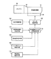
図6は、電子制御装置160による制御機能の要部を説明する機能ブロック線図である。図6において、ライン圧制御手段162は、基本的には、アクセル開度或いはスロットル開度に応じた大きさの信号圧PSLTをリニアソレノイドバルブSLTから第1ライン圧調圧弁82および第2ライン圧調圧弁84へ供給し、エンジン負荷等に応じた第1ライン油圧PL1および第2ライン油圧PL2を基本値としてそれぞれ発生させる。 FIG. 6 is a functional block diagram for explaining a main part of the control function by the electronic control unit 160. In FIG. 6, the line pressure control means 162 basically converts the signal pressure PSLT having a magnitude corresponding to the accelerator opening or the throttle opening from the linear solenoid valve SLT to the first line pressure regulating valve 82 and the second line. Supplyed to the pressure regulating valve 84, the first line oil pressure PL1 and the second line oil pressure PL2 corresponding to the engine load or the like are generated as basic values.

他の制御手段164は、後述の作動油の温度上昇促進のための低油温時ライン圧上昇制御とは異なる理由でライン油圧を上昇させる他の制御を実行するものであり、たとえば、シフトレバー72のN→Dシフト時の応答性を高めるためにN→Dシフト操作が行われると、所定期間だけ第1ライン油圧PL1および第2ライン圧PL2を上昇させる制御や、エンジン26のアイドル回転速度NIDLが高いときは、そのエンジン26のアイドル回転速度NIDLに応じて第1ライン圧PL1および第2ライン圧PL2を上昇させる制御を実行する。 The other control means 164 executes another control for increasing the line hydraulic pressure for a reason different from the low oil temperature line pressure increase control for promoting the hydraulic oil temperature increase described later. For example, the shift lever When the N → D shift operation is performed in order to increase the responsiveness during the N → D shift of 72, the control for increasing the first line hydraulic pressure PL1 and the second line pressure PL2 only for a predetermined period, and the idle rotation speed of the engine 26 When N IDL is high, control is performed to increase the first line pressure PL1 and the second line pressure PL2 in accordance with the idle rotation speed N IDL of the engine 26.

低油温判定手段166は、AT油温センサ78により検出された自動変速機10内の作動油の温度TOILが予め設定された所定の判定値T1以下であるか否かを判定する。この判定値T1は、たとえば0℃或いはそれ以下に設定された値である。シフトポジション判定手段168は、シフトレバー72のシフト操作装置が車両走行可能な走行ポジションすなわちPポジション、Nポジション以外のポジションに操作されているか否かを、レバーポジションセンサ74からのレバーポジション(操作位置)PSHを示す信号に基づいて、或いは入力軸回転速度NIN(=タービン回転速度N) に基づいて判定する。車両停止判定手段170は、車両が停止しているか否かを、車速センサ66からの車速V(出力軸24の回転速度NOUTに対応)を示す信号に基づいて、或いは入力軸回転速度NIN(=タービン回転速度N) に基づいて判定する。 The low oil temperature determination means 166 determines whether or not the temperature T OIL of the hydraulic oil in the automatic transmission 10 detected by the AT oil temperature sensor 78 is equal to or lower than a predetermined determination value T1. This determination value T1 is a value set at, for example, 0 ° C. or lower. The shift position determination means 168 determines whether or not the shift operation device of the shift lever 72 is operated to a travel position where the vehicle can travel, that is, a position other than the P position and the N position. ) Based on a signal indicating P SH or based on the input shaft rotational speed N IN (= turbine rotational speed N T ). The vehicle stop determination unit 170 determines whether or not the vehicle is stopped based on a signal indicating the vehicle speed V (corresponding to the rotational speed N OUT of the output shaft 24) from the vehicle speed sensor 66 or the input shaft rotational speed N IN. (= Turbine rotational speed NT )

低油温時ライン圧上昇制御手段172は、上記低油温判定手段166により自動変速機10内の作動油の温度TOILが所定の判定値T1以下であると判定され、上記シフトポジション判定手段168により車両のシフトレバー72のシフト操作装置が車両走行可能な走行ポジションに操作されていると判定され、且つ、上記車両停止判定手段170により車両が停止していると判定された低油温時ライン圧上昇条件成立の場合は、作動油の温度TOILの暖気が完了し且つライン圧上昇を伴う他の制御が実行されていないときに用いられる通常の値よりも十分に暖気促進機能が得られるように高く設定したライン圧指令値A(kPa)をライン圧制御手段162に与えることにより、その低油温時ライン圧上昇条件不成立の場合に比較して第1ライン圧PL1をそのライン圧指令値A或いはそれ以上の値( この場合は下限指令値となる) に上昇させる。 The low oil temperature line pressure increase control means 172 determines that the low oil temperature determination means 166 determines that the temperature T OIL of the hydraulic oil in the automatic transmission 10 is equal to or lower than a predetermined determination value T1, and the shift position determination means. 168, when it is determined that the shift operation device of the shift lever 72 of the vehicle is operated to a travel position where the vehicle can travel, and the vehicle stop determination means 170 determines that the vehicle is stopped. When the line pressure increase condition is satisfied, a warming promotion function sufficiently higher than the normal value used when the warming of the hydraulic oil temperature T OIL is completed and no other control accompanying the line pressure increase is executed is obtained. By giving the line pressure command value A (kPa) set so high as to the line pressure control means 162, the line pressure increase condition at low oil temperature is not satisfied. Raising the first line pressure PL1 in the line pressure command value A or more values (the lower limit command value in this case).

他制御必要圧判定手段174は、上記低油温時ライン圧上昇制御手段172による低油温時ライン圧上昇制御とは異なるライン圧上昇を伴う他の制御、たとえばシフトレバー72のN→Dシフト時の応答性を高めるためにN→Dシフト操作が行われると、所定期間だけ第1ライン油圧PL1および第2ライン圧PL2を上昇させる制御や、エンジン26のアイドル回転速度NIDLが高いときは、そのエンジン26のアイドル回転速度NIDLに応じて第1ライン圧PL1および第2ライン圧PL2を上昇させる制御に必要とされる所定のライン圧上昇値B(kPa)が前記低油温時ライン圧A(kPa)以上であるか否かを判定する。 The other control necessary pressure determination means 174 is a control other than the low oil temperature line pressure increase control by the low oil temperature line pressure increase control means 172, for example, an N → D shift of the shift lever 72. When the N → D shift operation is performed in order to improve the responsiveness of the time, when the control for increasing the first line hydraulic pressure PL1 and the second line pressure PL2 for a predetermined period or when the idling speed N IDL of the engine 26 is high The predetermined line pressure increase value B (kPa) required for increasing the first line pressure PL1 and the second line pressure PL2 in accordance with the idle speed N IDL of the engine 26 is the low oil temperature line. It is determined whether or not the pressure is A (kPa) or more.

前記低油温時ライン圧上昇制御手段172は、上記他制御必要圧判定手段174により、低油温時ライン圧上昇条件成立時において前記他の制御のための所定の上昇値B(kPa)が低油温時ライン圧A(kPa)以上である場合は、その低油温時ライン圧Aとするための低油温時ライン圧制御を実行しない。   The low oil temperature line pressure increase control means 172 uses the other control required pressure determination means 174 to set a predetermined increase value B (kPa) for the other control when the low oil temperature line pressure increase condition is satisfied. When it is equal to or higher than the low oil temperature line pressure A (kPa), the low oil temperature line pressure control for setting the low oil temperature line pressure A is not executed.

図7は、電子制御装置160の制御作動の要部すなわち低油温時ライン圧上昇制御ルーチンによる制御作動を説明するフローチャートであり、例えば数msec乃至数十msec程度の極めて短いサイクルタイムで繰り返し実行されるものである。   FIG. 7 is a flowchart for explaining the main part of the control operation of the electronic control unit 160, that is, the control operation by the line pressure increase control routine at the time of low oil temperature. It is what is done.

先ず、前記低油温判定手段166に対応するステップ(以下、ステップを省略する)S1において、AT油温センサ78により検出された自動変速機10内の作動油の温度TOILがたとえば0℃程度に予め設定された所定の判定値T1以下であるか否かが判断される。このS1の判断が肯定される場合は、前記シフトポジション判定手段168および車両停止判定手段170に対応するS2において、タービン回転速度センサ76により検出された自動変速機10の入力軸回転速度NIN(=タービン回転速度N) が予め設定された判定値N1よりも小さいか否かが判断される。この判定値N1は零に近い値たとえば5〜10rpmに設定されている。上記自動変速機10の入力軸回転速度NINがその判定値N1よりも小さい場合は、車両が停止状態であり且つシフトレバー72が走行ポジションに位置していることを示している。シフトレバー72が走行ポジションに位置していると、自動変速機10内の動力伝達経路が成立して、入力軸回転速度NINは自動変速機10の変速比を出力軸回転速度NOUTに掛けた値となるので、車両停止状態でなければS2の判定が否定されるとともに、シフトレバー72がPポジションやNポジションである場合も、自動変速機10内のクラッチC1およびC2が解放されて入力軸回転速度NINが=アイドル回転速度となるので、S2の判定が否定される。 First, in a step (hereinafter, step is omitted) S1 corresponding to the low oil temperature determination means 166, the temperature T OIL of the hydraulic oil in the automatic transmission 10 detected by the AT oil temperature sensor 78 is about 0 ° C., for example. It is determined whether or not it is equal to or less than a predetermined determination value T1 set in advance. If the determination in S1 is affirmative, in S2 corresponding to the shift position determination unit 168 and the vehicle stop determination unit 170, the input shaft rotation speed N IN () of the automatic transmission 10 detected by the turbine rotation speed sensor 76. = It is determined whether or not the turbine rotational speed N T ) is smaller than a predetermined determination value N1. This determination value N1 is set to a value close to zero, for example, 5 to 10 rpm. When the input shaft rotational speed N IN of the automatic transmission 10 is less than the determination value N1 indicates that the vehicle is in a stopped state and the shift lever 72 is located at the drive position. When the shift lever 72 is positioned at the running position, the power transmission path in the automatic transmission 10 is established, the input shaft rotational speed N IN is multiplied by the gear ratio of the automatic transmission 10 to the output shaft speed N OUT Therefore, if the vehicle is not stopped, the determination in S2 is negative, and the clutches C1 and C2 in the automatic transmission 10 are released and input even when the shift lever 72 is in the P position or the N position. Since the shaft rotation speed NIN is equal to the idle rotation speed, the determination in S2 is negative.

上記S2の判断が肯定された場合は、前記他制御必要圧判定手段174に対応するS3において、低油温時ライン圧上昇制御手段172による低油温時ライン圧上昇制御とは異なるライン圧上昇を伴う他の制御、たとえばシフトレバー72のN→Dシフト時の応答性を高めるためにN→Dシフト操作が行われると、所定期間だけ第1ライン油圧PL1および第2ライン圧PL2を上昇させる制御や、エンジン26のアイドル回転速度NIDLが高いときは、そのエンジン26のアイドル回転速度NIDLに応じて第1ライン圧PL1および第2ライン圧PL2を上昇させる制御に必要とされる所定のライン圧上昇値B(kPa)が前記低油温時ライン圧A(kPa)以下であるか否かが判定される。 If the determination in S2 is affirmative, in S3 corresponding to the other control required pressure determination unit 174, the line pressure increase is different from the low oil temperature line pressure increase control by the low oil temperature line pressure increase control unit 172. When the N → D shift operation is performed to improve the response of the shift lever 72 during N → D shift, for example, the first line hydraulic pressure PL1 and the second line pressure PL2 are increased for a predetermined period. When the control and the idle rotation speed N IDL of the engine 26 are high, predetermined control required for increasing the first line pressure PL1 and the second line pressure PL2 according to the idle rotation speed N IDL of the engine 26 is performed. It is determined whether or not the line pressure increase value B (kPa) is equal to or lower than the low oil temperature line pressure A (kPa).

上記S1、S2、S3の判断が共に肯定された場合、すなわち、自動変速機10内の作動油の温度TOILが所定の判定値T1以下であり、車両のシフトレバー72のシフト操作装置が車両走行可能な走行ポジションに操作されており、車両が停止しているという低油温時ライン圧上昇条件が成立するとともに、低油温時ライン圧上昇制御手段172による低油温時ライン圧上昇制御とは異なるライン圧上昇を伴う他の制御に必要とされる所定のライン圧上昇値B(kPa)が前記低油温時ライン圧A(kPa)以下である場合は、前記低油温時ライン圧上昇制御手段172に対応するS4において、作動油の温度TOILの暖気が完了し且つライン圧上昇を伴う他の制御が実行されていないときに用いられる通常の値よりも十分に暖気促進機能が得られるように高く設定したライン圧指令値A(kPa)がライン圧制御手段162に与えられることにより、その低油温時ライン圧上昇条件不成立の場合に比較して第1ライン圧PL1がそのライン圧指令値A或いはそれ以上の値( この場合は下限指令値となる) に上昇させられる。 When the determinations of S1, S2, and S3 are all affirmative, that is, the temperature T OIL of the hydraulic oil in the automatic transmission 10 is equal to or lower than a predetermined determination value T1, and the shift operation device of the shift lever 72 of the vehicle is The low oil temperature line pressure increase control is performed by the low oil temperature line pressure increase control means 172 while the low oil temperature line pressure increase condition that the vehicle is stopped is operated. When a predetermined line pressure increase value B (kPa) required for other control accompanied by a line pressure increase different from that is equal to or lower than the low oil temperature line pressure A (kPa), the low oil temperature line in S4 corresponding to the pressure increase control means 172, sufficiently warm prompting than the normal value used when the temperature T oIL of the warm air of the hydraulic oil is another control with the and line pressure rises completed not running The line pressure command value A (kPa) set high so as to obtain the function is given to the line pressure control means 162, so that the first line pressure PL1 is compared with the case where the low oil temperature line pressure increase condition is not satisfied. Is increased to the line pressure command value A or higher (in this case, the lower limit command value).

しかし、上記S1、S2、S3の判断のいずれか1つが否定された場合は、前記他の制御手段164に対応するS5において、作動油の温度上昇促進のための低油温時ライン圧上昇制御とは異なる理由でライン油圧を上昇させる他の制御、たとえば、シフトレバー72のN→Dシフト時の応答性を高めるためにN→Dシフト操作が行われると、所定期間だけ第1ライン油圧PL1および第2ライン圧PL2を上昇させる制御や、エンジン26のアイドル回転速度NIDLが高いときは、そのエンジン26のアイドル回転速度NIDLに応じて第1ライン圧PL1および第2ライン圧PL2を上昇させる制御などが実行される。 However, if any one of the above determinations of S1, S2, and S3 is denied, in S5 corresponding to the other control means 164, the low oil temperature line pressure increase control for promoting the temperature increase of the hydraulic oil. When the N → D shift operation is performed to increase the response of the shift lever 72 during N → D shift, for example, for increasing the line hydraulic pressure for a different reason, the first line hydraulic pressure PL1 is set for a predetermined period. When the idle rotation speed N IDL of the engine 26 is high or when the engine 26 idle speed N IDL is high, the first line pressure PL1 and the second line pressure PL2 are increased according to the idle rotation speed N IDL of the engine 26. Control is performed.

上述のように、本実施例の車両用自動変速機10の油圧制御装置によれば、低油温判定手段166により作動油の温度TOILが所定値T1以下であると判定され、シフトポジション判定手段168により車両のシフトレバー72が走行ポジションに操作されていると判定され、且つ、車両停止判定手段170により車両が停止していると判定された低油温時ライン圧上昇条件成立の場合において、低油温時ライン圧上昇制御手段172により、低油温時ライン圧上昇条件不成立の場合に比較して第1ライン圧PL1が上昇させられるので、その第1ライン圧PL1の上昇によって作動油に対して与えられる仕事量が増加させられてその作動油の温度上昇が積極的に促進される。しかも、車両停止時のみにライン圧が上昇させられるので、車両走行時の動力性能が損なわれることがない。 As described above, according to the hydraulic control device for the vehicle automatic transmission 10 of the present embodiment, the low oil temperature determination unit 166 determines that the hydraulic oil temperature T OIL is equal to or less than the predetermined value T1, and shift position determination. When it is determined by the means 168 that the shift lever 72 of the vehicle has been operated to the travel position and the vehicle stop determination means 170 has determined that the vehicle has stopped, the low oil temperature line pressure increase condition is satisfied. The first line pressure PL1 is increased by the low oil temperature line pressure increase control means 172 as compared with the case where the low oil temperature line pressure increase condition is not satisfied. The amount of work given to the oil is increased, and the temperature rise of the hydraulic oil is positively promoted. In addition, since the line pressure is increased only when the vehicle is stopped, the power performance during traveling of the vehicle is not impaired.

また、本実施例の車両用自動変速機10の油圧制御装置によれば、低油温時ライン圧上昇制御手段172は、前記低油温時ライン圧上昇条件成立の場合は、その低油温時ライン圧上昇条件不成立の場合よりも高くなるように予め設定された低油温時ライン圧Aとなるように第1ライン圧PL1を上昇制御するので、その低油温時ライン圧Aとなるように第1ライン圧PL1が上昇させられることにより、作動油に対して与えられる仕事量が増加させられてその作動油の温度上昇が積極的に促進される。   Further, according to the hydraulic control device for the vehicle automatic transmission 10 of the present embodiment, the low oil temperature line pressure increase control means 172 determines that the low oil temperature line pressure increase condition is satisfied when the low oil temperature line pressure increase condition is satisfied. Since the first line pressure PL1 is controlled to increase so as to be set to a low oil temperature line pressure A that is preset to be higher than when the time line pressure increase condition is not established, the low oil temperature line pressure A is obtained. As the first line pressure PL1 is increased as described above, the amount of work given to the hydraulic oil is increased, and the temperature increase of the hydraulic oil is positively promoted.

また、本実施例の車両用自動変速機10の油圧制御装置によれば、前記低油温時ライン圧上昇制御手段172は、前記低油温時ライン圧上昇条件成立時において、前記低油温時ライン圧上昇制御手段172よる低油温時ライン圧上昇制御とは異なる他の制御のための所定の上昇値Bがその低油温時ライン圧上昇制御のライン圧A以上である場合は、その低油温時ライン圧上昇制御を実行しないので、重ねてライン圧上昇制御が実行されることが回避される。   Further, according to the hydraulic control device for the vehicle automatic transmission 10 of the present embodiment, the low oil temperature line pressure increase control means 172 provides the low oil temperature when the low oil temperature line pressure increase condition is satisfied. When the predetermined increase value B for control other than the low oil temperature line pressure increase control by the hour line pressure increase control means 172 is equal to or higher than the line pressure A of the low oil temperature line pressure increase control, Since the line pressure increase control at the time of low oil temperature is not executed, it is avoided that the line pressure increase control is executed repeatedly.

また、本実施例の車両用自動変速機10の油圧制御装置によれば、(a) 自動変速機10の入力軸回転速度を検出する入力軸回転速度センサが備えられ、(b) 前記車両停止判定手段170は、入力軸回転速度NINが予め設定された回転速度判定値N1よりも小さい場合に、前記車両が停止していると判定し、(c) 前記シフトポジション判定手段168は、その入力軸回転速度センサにより検出された入力軸回転速度NINが予め設定された回転速度判定値N1を下回る場合に、シフトレバー72が走行ポジションに操作されていると判定することから、車両が停止していることおよび走行ポジションに操作されていることが、自動変速機10の入力軸回転速度NINに基づいて一挙に判定される。 Further, according to the hydraulic control device for the vehicle automatic transmission 10 of the present embodiment, (a) an input shaft rotation speed sensor for detecting the input shaft rotation speed of the automatic transmission 10 is provided, and (b) the vehicle stop The determination means 170 determines that the vehicle is stopped when the input shaft rotation speed N IN is smaller than a preset rotation speed determination value N1, and (c) the shift position determination means 168 When the input shaft rotation speed N IN detected by the input shaft rotation speed sensor is lower than the preset rotation speed determination value N1, it is determined that the shift lever 72 is operated to the travel position, so the vehicle stops. It is determined at a stroke based on the input shaft rotational speed N IN of the automatic transmission 10 that the vehicle is operating and being operated to the traveling position.

以上、本発明の実施例を図面に基づいて詳細に説明したが、本発明はその他の態様においても適用される。   As mentioned above, although the Example of this invention was described in detail based on drawing, this invention is applied also in another aspect.

例えば、前述の実施例の油圧制御回路50において、第1ライン圧PL1を制御する第1ライン圧調圧弁82および第2ライン圧PL2を制御する第2ライン圧調圧弁84が設けられていたが、いずれか一方が設けられた油圧制御回路50であってもよい。   For example, in the hydraulic control circuit 50 of the above-described embodiment, the first line pressure regulating valve 82 that controls the first line pressure PL1 and the second line pressure regulating valve 84 that controls the second line pressure PL2 are provided. The hydraulic control circuit 50 provided with either one of them may be used.

また、前述の実施例の車両では、有段式の自動変速機10が設けられていたが、変速比が無段階に変化させられる無段変速機であってもよい。   Further, although the stepped automatic transmission 10 is provided in the vehicle of the above-described embodiment, it may be a continuously variable transmission whose speed ratio is continuously variable.

また、前述の実施例の車両では、トルクコンバータ28が設けられていたが、それに替えてフルードカップリングが設けられていてもよい。   In the vehicle of the above-described embodiment, the torque converter 28 is provided, but a fluid coupling may be provided instead.

また、前述の実施例の車両では、原動機として、エンジン26が設けられていたが、エンジンおよび電動機、或いは電動機が設けられていてもよい。   Moreover, in the vehicle of the above-mentioned Example, although the engine 26 was provided as a motor | power_engine, an engine and an electric motor or an electric motor may be provided.

なお、上述したのはあくまでも一実施形態であり、本発明は当業者の知識に基づいて種々の変更、改良を加えた態様で実施することができる。   The above description is only an embodiment, and the present invention can be implemented in variously modified and improved forms based on the knowledge of those skilled in the art.

本発明が適用された車両用自動変速機の構成を説明する骨子図である。BRIEF DESCRIPTION OF THE DRAWINGS FIG. 1 is a skeleton diagram illustrating a configuration of a vehicle automatic transmission to which the present invention is applied. 図1の車両用自動変速機の複数のギヤ段を成立させる際の油圧式摩擦係合装置の作動の組み合わせを説明する作動図表である。FIG. 2 is an operation chart for explaining a combination of operations of the hydraulic friction engagement device when establishing a plurality of gear stages of the vehicle automatic transmission of FIG. 1. クラッチおよびブレーキの各油圧アクチュエータやロックアップクラッチの作動を制御するリニアソレノイドバルブに関する回路図であって、油圧制御装置としての油圧制御回路を示す図である。It is a circuit diagram regarding the linear solenoid valve which controls the action | operation of each hydraulic actuator of a clutch and a brake, and a lockup clutch, Comprising: It is a figure which shows the hydraulic control circuit as a hydraulic control apparatus. 図1の自動変速機などを制御するために車両に設けられた制御系統の要部を説明するブロック線図である。FIG. 2 is a block diagram illustrating a main part of a control system provided in the vehicle for controlling the automatic transmission of FIG. 1 and the like. 図4のシフトレバーの操作位置を説明する図である。It is a figure explaining the operation position of the shift lever of FIG. 図4の電子制御装置による制御機能の要部を説明する機能ブロック線図である。It is a functional block diagram explaining the principal part of the control function by the electronic controller of FIG. 図4の電子制御装置の制御作動を説明するフローチャートである。It is a flowchart explaining the control action of the electronic controller of FIG.

符号の説明Explanation of symbols

10:車両用自動変速機
52:油圧ポンプ
72:シフトレバー(シフト操作装置)
76:タービン回転速度センサ( 入力軸回転速度センサ)
82:第1ライン圧調圧弁、84:第2ライン圧調圧弁( ライン圧制御装置)
SLT:リニアソレノイドバルブ(ライン圧制御装置)
160:電子制御装置(油圧制御装置)
166:低油温判定手段
168:シフトポジション判定手段
170:車両停止判定手段
172:低油温時ライン圧上昇制御手段
10: Automatic transmission for vehicle 52: Hydraulic pump 72: Shift lever (shift operation device)
76: Turbine rotational speed sensor (input shaft rotational speed sensor)
82: First line pressure regulating valve, 84: Second line pressure regulating valve (line pressure control device)
SLT: Linear solenoid valve (Line pressure control device)
160: Electronic control device (hydraulic control device)
166: Low oil temperature determination means 168: Shift position determination means 170: Vehicle stop determination means 172: Low oil temperature line pressure increase control means

Claims (4)

油圧ポンプから圧送された作動油を所定のライン圧に調圧するライン圧制御装置を備えた車両用自動変速機の油圧制御装置であって、
前記作動油の温度が所定値以下であるか否かを判定する低油温判定手段と、
車両のシフト操作装置が走行ポジションに操作されているか否かを判定するシフトポジション判定手段と、
車両が停止しているか否かを判定する車両停止判定手段と、
前記低油温判定手段により前記作動油の温度が所定値以下であると判定され、前記シフトポジション判定手段により前記車両のシフト操作装置が走行ポジションに操作されていると判定され、且つ、前記車両停止判定手段により車両が停止していると判定された低油温時ライン圧上昇条件成立の場合は、該低油温時ライン圧上昇条件不成立の場合に比較して前記ライン圧を上昇させる低油温時ライン圧上昇制御手段と
を、含むことを特徴とする車両用自動変速機の油圧制御装置。
A hydraulic control device for an automatic transmission for a vehicle including a line pressure control device that adjusts hydraulic oil pumped from a hydraulic pump to a predetermined line pressure,
Low oil temperature determination means for determining whether the temperature of the hydraulic oil is equal to or lower than a predetermined value;
Shift position determination means for determining whether or not the shift operation device of the vehicle is operated to the travel position;
Vehicle stop determination means for determining whether or not the vehicle is stopped;
The low oil temperature determination means determines that the temperature of the hydraulic oil is equal to or lower than a predetermined value, the shift position determination means determines that the shift operation device of the vehicle is operated to a travel position, and the vehicle When the low oil temperature line pressure increase condition is satisfied when the vehicle is determined to be stopped by the stop determination means, the line pressure is increased less than when the low oil temperature line pressure increase condition is not satisfied. And a hydraulic pressure control device for an automatic transmission for a vehicle, comprising: an oil temperature line pressure increase control means.
前記低油温時ライン圧上昇制御手段は、前記低油温時ライン圧上昇条件成立の場合は、該低油温時ライン圧上昇条件不成立の場合よりも高くなるように予め設定された低油温時ライン圧となるようにライン圧を制御するものである請求項1の車両用自動変速機の油圧制御装置。 The low oil temperature line pressure increase control means is set in advance so as to be higher when the low oil temperature line pressure increase condition is satisfied than when the low oil temperature line pressure increase condition is not satisfied. 2. The hydraulic control device for an automatic transmission for a vehicle according to claim 1, wherein the line pressure is controlled so as to be a warm line pressure. 前記低油温時ライン圧上昇制御手段は、前記低油温時ライン圧上昇条件成立時において、前記低油温時ライン圧上昇制御手段よる低油温時ライン圧上昇制御とは異なる他の制御のための所定の上昇値が該低油温時ライン圧上昇制御のライン圧以上である場合は、該低油温時ライン圧上昇制御を実行しないことを特徴とする請求項2の車両用自動変速機の油圧制御装置。 The low oil temperature line pressure increase control means is another control different from the low oil temperature line pressure increase control by the low oil temperature line pressure increase control means when the low oil temperature line pressure increase condition is satisfied. 3. The vehicle automatic according to claim 2, wherein the low oil temperature line pressure increase control is not executed when a predetermined increase value for the oil pressure is equal to or higher than the line pressure of the low oil temperature line pressure increase control. Hydraulic control device for transmission. 前記自動変速機の入力軸回転速度を検出する入力軸回転速度センサを備え、
前記車両停止判定手段は、該入力軸回転速度センサにより検出された入力軸回転速度が予め設定された回転速度判定値を下回る場合に、前記車両が停止していると判定し、
前記シフトポジション判定手段は、該入力軸回転速度センサにより検出された入力軸回転速度が予め設定された回転速度判定値を下回る場合は、前記シフト操作装置が走行ポジションに操作されていると判定することを特徴とする請求項1乃至3のいずれかの車両用自動変速機の油圧制御装置。
An input shaft rotation speed sensor for detecting an input shaft rotation speed of the automatic transmission;
The vehicle stop determination means determines that the vehicle is stopped when the input shaft rotation speed detected by the input shaft rotation speed sensor is lower than a preset rotation speed determination value;
The shift position determining means determines that the shift operating device is operated to the travel position when the input shaft rotational speed detected by the input shaft rotational speed sensor is below a preset rotational speed determination value. The hydraulic control device for an automatic transmission for a vehicle according to any one of claims 1 to 3.
JP2006322405A 2006-11-29 2006-11-29 Hydraulic control device for automatic transmission for vehicle Expired - Fee Related JP4983230B2 (en)

Priority Applications (1)

Application Number Priority Date Filing Date Title
JP2006322405A JP4983230B2 (en) 2006-11-29 2006-11-29 Hydraulic control device for automatic transmission for vehicle

Applications Claiming Priority (1)

Application Number Priority Date Filing Date Title
JP2006322405A JP4983230B2 (en) 2006-11-29 2006-11-29 Hydraulic control device for automatic transmission for vehicle

Publications (2)

Publication Number Publication Date
JP2008133941A JP2008133941A (en) 2008-06-12
JP4983230B2 true JP4983230B2 (en) 2012-07-25

Family

ID=39558918

Family Applications (1)

Application Number Title Priority Date Filing Date
JP2006322405A Expired - Fee Related JP4983230B2 (en) 2006-11-29 2006-11-29 Hydraulic control device for automatic transmission for vehicle

Country Status (1)

Country Link
JP (1) JP4983230B2 (en)

Family Cites Families (4)

* Cited by examiner, † Cited by third party
Publication number Priority date Publication date Assignee Title
JPH0298254U (en) * 1989-01-25 1990-08-06
JPH0783320A (en) * 1993-09-14 1995-03-28 Nissan Motor Co Ltd Line pressure controller of automatic transmission
JP3560925B2 (en) * 2001-04-12 2004-09-02 本田技研工業株式会社 Linear solenoid valve and abnormality detection device and method for hydraulic device using the same
JP4157408B2 (en) * 2003-03-31 2008-10-01 ジヤトコ株式会社 Hydraulic control device for automatic transmission

Also Published As

Publication number Publication date
JP2008133941A (en) 2008-06-12

Similar Documents

Publication Publication Date Title
JP4158792B2 (en) Hydraulic control device for automatic transmission for vehicle
JP4353148B2 (en) Control device for automatic transmission
JP5338982B2 (en) Control device for automatic transmission for vehicle
JP3855966B2 (en) Neutral control device for automatic transmission for vehicles
JP2005003193A (en) Controller of lockup clutch for vehicle
JP4779938B2 (en) Hydraulic control device for vehicle
JP3843921B2 (en) Vehicle drive control device
JP5035376B2 (en) Control device for vehicle lock-up clutch
WO2012042834A1 (en) Automatic transmission controller
JP4206852B2 (en) Hydraulic control circuit for automatic transmission for vehicles
JP4774680B2 (en) Hydraulic control device for automatic transmission for vehicle
JP2005344741A (en) Hydraulic control device for vehicular automatic transmission
JP4162024B2 (en) Control device for automatic transmission for vehicle
JP4899441B2 (en) Vehicle control device
JP4577138B2 (en) Hydraulic control device for automatic transmission for vehicle
JP4923547B2 (en) Shift control device for automatic transmission for vehicle
JP4446821B2 (en) Hydraulic control device for automatic transmission for vehicle
JP4654872B2 (en) Hydraulic control device for automatic transmission for vehicle
JP2006046387A (en) Hydraulic controller of automatic transmission
US20170356545A1 (en) Vehicle and Control Method for Vehicle
JP4983230B2 (en) Hydraulic control device for automatic transmission for vehicle
JP5494827B2 (en) Control device for automatic transmission for vehicle
JP5299310B2 (en) Control device for automatic transmission
JP5035221B2 (en) Shift control device for automatic transmission
JP2007064464A (en) Gear shift control device of automatic transmission for vehicle

Legal Events

Date Code Title Description
A621 Written request for application examination

Free format text: JAPANESE INTERMEDIATE CODE: A621

Effective date: 20091006

A977 Report on retrieval

Free format text: JAPANESE INTERMEDIATE CODE: A971007

Effective date: 20110922

A131 Notification of reasons for refusal

Free format text: JAPANESE INTERMEDIATE CODE: A131

Effective date: 20111004

TRDD Decision of grant or rejection written
A01 Written decision to grant a patent or to grant a registration (utility model)

Free format text: JAPANESE INTERMEDIATE CODE: A01

Effective date: 20120327

A01 Written decision to grant a patent or to grant a registration (utility model)

Free format text: JAPANESE INTERMEDIATE CODE: A01

A61 First payment of annual fees (during grant procedure)

Free format text: JAPANESE INTERMEDIATE CODE: A61

Effective date: 20120409

FPAY Renewal fee payment (event date is renewal date of database)

Free format text: PAYMENT UNTIL: 20150511

Year of fee payment: 3

LAPS Cancellation because of no payment of annual fees