JP2017190815A - Piping structure and boiler system - Google Patents
Piping structure and boiler system Download PDFInfo
- Publication number
- JP2017190815A JP2017190815A JP2016079791A JP2016079791A JP2017190815A JP 2017190815 A JP2017190815 A JP 2017190815A JP 2016079791 A JP2016079791 A JP 2016079791A JP 2016079791 A JP2016079791 A JP 2016079791A JP 2017190815 A JP2017190815 A JP 2017190815A
- Authority
- JP
- Japan
- Prior art keywords
- pipe
- piping
- deformation
- cross
- steel frame
- Prior art date
- Legal status (The legal status is an assumption and is not a legal conclusion. Google has not performed a legal analysis and makes no representation as to the accuracy of the status listed.)
- Granted
Links
Images
Classifications
-
- E—FIXED CONSTRUCTIONS
- E04—BUILDING
- E04H—BUILDINGS OR LIKE STRUCTURES FOR PARTICULAR PURPOSES; SWIMMING OR SPLASH BATHS OR POOLS; MASTS; FENCING; TENTS OR CANOPIES, IN GENERAL
- E04H5/00—Buildings or groups of buildings for industrial or agricultural purposes
- E04H5/02—Buildings or groups of buildings for industrial purposes, e.g. for power-plants or factories
-
- F—MECHANICAL ENGINEERING; LIGHTING; HEATING; WEAPONS; BLASTING
- F16—ENGINEERING ELEMENTS AND UNITS; GENERAL MEASURES FOR PRODUCING AND MAINTAINING EFFECTIVE FUNCTIONING OF MACHINES OR INSTALLATIONS; THERMAL INSULATION IN GENERAL
- F16F—SPRINGS; SHOCK-ABSORBERS; MEANS FOR DAMPING VIBRATION
- F16F15/00—Suppression of vibrations in systems; Means or arrangements for avoiding or reducing out-of-balance forces, e.g. due to motion
- F16F15/02—Suppression of vibrations of non-rotating, e.g. reciprocating systems; Suppression of vibrations of rotating systems by use of members not moving with the rotating systems
- F16F15/04—Suppression of vibrations of non-rotating, e.g. reciprocating systems; Suppression of vibrations of rotating systems by use of members not moving with the rotating systems using elastic means
- F16F15/08—Suppression of vibrations of non-rotating, e.g. reciprocating systems; Suppression of vibrations of rotating systems by use of members not moving with the rotating systems using elastic means with rubber springs ; with springs made of rubber and metal
-
- F—MECHANICAL ENGINEERING; LIGHTING; HEATING; WEAPONS; BLASTING
- F16—ENGINEERING ELEMENTS AND UNITS; GENERAL MEASURES FOR PRODUCING AND MAINTAINING EFFECTIVE FUNCTIONING OF MACHINES OR INSTALLATIONS; THERMAL INSULATION IN GENERAL
- F16L—PIPES; JOINTS OR FITTINGS FOR PIPES; SUPPORTS FOR PIPES, CABLES OR PROTECTIVE TUBING; MEANS FOR THERMAL INSULATION IN GENERAL
- F16L27/00—Adjustable joints; Joints allowing movement
- F16L27/10—Adjustable joints; Joints allowing movement comprising a flexible connection only
-
- F—MECHANICAL ENGINEERING; LIGHTING; HEATING; WEAPONS; BLASTING
- F22—STEAM GENERATION
- F22B—METHODS OF STEAM GENERATION; STEAM BOILERS
- F22B37/00—Component parts or details of steam boilers
- F22B37/02—Component parts or details of steam boilers applicable to more than one kind or type of steam boiler
- F22B37/10—Water tubes; Accessories therefor
Landscapes
- Engineering & Computer Science (AREA)
- General Engineering & Computer Science (AREA)
- Mechanical Engineering (AREA)
- Architecture (AREA)
- Physics & Mathematics (AREA)
- Chemical & Material Sciences (AREA)
- Thermal Sciences (AREA)
- Structural Engineering (AREA)
- Civil Engineering (AREA)
- Combustion & Propulsion (AREA)
- Acoustics & Sound (AREA)
- Aviation & Aerospace Engineering (AREA)
- Vibration Prevention Devices (AREA)
- Joints Allowing Movement (AREA)
- Buildings Adapted To Withstand Abnormal External Influences (AREA)
- Supports For Pipes And Cables (AREA)
Abstract
Description
本発明は、免震装置を有する支持構造体に固定されている配管を有する配管構造、及びボイラシステムに関する。 The present invention relates to a pipe structure having a pipe fixed to a support structure having a seismic isolation device, and a boiler system.
発電用石炭焚きボイラ、重油焚きボイラといった大型ボイラは、通常、脱硝装置、エアヒータをはじめとする附帯機器とともに支持構造体の支持鉄骨に支持されている。
ボイラの支持構造体としては、積層ゴム等によって形成されて、支持構造体を構成する支持鉄骨を支持する免震装置を有するものが知られている。特許文献1には、作用する地震力を低減するために、支持鉄骨を構成する柱に生じる水平反力の大きさに応じて免震特性が設定されている免震装置が記載されている。
Large boilers such as a coal-fired boiler for power generation and a heavy oil fired boiler are usually supported by a supporting steel frame of a supporting structure together with ancillary equipment such as a denitration device and an air heater.
As a support structure of a boiler, one having a seismic isolation device that is formed of laminated rubber or the like and supports a support steel frame constituting the support structure is known.
ところで、ボイラには、例えば、タービンのような設備へ供給する高温・高圧の蒸気が流れる配管が接続される。ボイラが免震装置を有する支持構造体によって支持されている場合、免震装置によって支持されている支持鉄骨の水平方向の変位が大きくなるため、ボイラ側の配管とタービン側の配管との間の配管に大きな変形が生じる。
このような変形を吸収するために、ユニバーサルジョイント等を用いて変形を許容する構造等が知られているが、配管を流れる流体が高圧であると、流体の漏れが生じる可能性があるという課題があった。
By the way, for example, a pipe through which high-temperature and high-pressure steam supplied to equipment such as a turbine flows is connected to the boiler. When the boiler is supported by a support structure having a seismic isolation device, the horizontal displacement of the support steel frame supported by the seismic isolation device increases, so there is a problem between the boiler side piping and the turbine side piping. Large deformation occurs in the piping.
In order to absorb such deformation, a structure that allows deformation using a universal joint or the like is known. However, if the fluid flowing through the pipe is high pressure, there is a possibility that fluid leakage may occur. was there.
この発明は、免震装置によって支持されている第一の設備と、免震装置によって支持されていない第二の設備との間の相対位置が大きく変動した場合においても、配管にかかる変形を吸収することができる配管構造、及びボイラシステムを提供することを目的とする。 The present invention absorbs deformation of the pipe even when the relative position between the first facility supported by the seismic isolation device and the second facility not supported by the seismic isolation device varies greatly. It is an object of the present invention to provide a piping structure and a boiler system that can be used.
本発明の第一の態様によれば、配管構造は、第一の設備を支持する支持鉄骨と前記支持鉄骨を支持する免震装置を有する支持構造体に固定された配管であって、前記第一の設備と、前記免震装置によって支持されていない第二の設備とを接続する配管を有する配管構造であって、前記配管と、前記配管に設けられた変形吸収部と、を有する。 According to the first aspect of the present invention, the pipe structure is a pipe fixed to a support structure having a support steel frame that supports the first equipment and a seismic isolation device that supports the support steel frame. It is a piping structure which has piping which connects one installation and the 2nd installation which is not supported by the seismic isolation device, Comprising: It has the piping and the deformation absorption part provided in the piping.
このような構成によれば、地震により第一の設備と第二の設備との間の相対位置が大きく変動した場合においても、変形吸収部によって配管構造にかかる変形を吸収することができる。 According to such a configuration, even when the relative position between the first facility and the second facility greatly varies due to the earthquake, the deformation applied to the piping structure can be absorbed by the deformation absorbing portion.
上記配管構造において、前記配管は、前記第一の設備側の第一の配管と、前記第二の設備側の第二の配管と、を有し、前記変形吸収部は、前記第一の配管の端部から前記第一の配管と交差する方向に延在する第一交差配管と、前記第二の配管の端部から前記第二の配管と交差する方向に延在する第二交差配管と、前記第一交差配管の端部と前記第二交差配管の端部とを接続する接続配管と、を有してよい。 In the above piping structure, the pipe includes a first pipe on the first equipment side and a second pipe on the second equipment side, and the deformation absorbing portion is the first pipe. A first intersecting pipe extending from the end of the second pipe in a direction intersecting with the first pipe, and a second intersecting pipe extending from the end of the second pipe in a direction intersecting with the second pipe; And a connecting pipe that connects an end of the first intersecting pipe and an end of the second intersecting pipe.
このような構成によれば、それぞれの配管の曲げ変形、ねじれ変形によって、配管に生じる変形を吸収することができる。 According to such a structure, the deformation | transformation which arises in piping by bending deformation and torsional deformation of each piping can be absorbed.
上記配管構造において、前記第一の配管と前記第一交差配管とのなす角、前記第一交差配管と前記接続配管とのなす角、前記接続配管と前記第二交差配管とのなす角、及び前記第二交差配管と前記第二の配管とのなす角は、それぞれ直角であってよい。 In the above pipe structure, an angle formed by the first pipe and the first cross pipe, an angle formed by the first cross pipe and the connection pipe, an angle formed by the connection pipe and the second cross pipe, and The angles formed by the second intersecting pipe and the second pipe may each be a right angle.
このような構成によれば、変形吸収部をコンパクトに形成することができる。 According to such a structure, a deformation | transformation absorption part can be formed compactly.
上記配管構造において、前記第一の配管と前記第一交差配管とのなす角、及び前記第二交差配管と前記第二の配管とのなす角は、鈍角であり、前記接続配管は、前記第一の配管及び前記第二の配管に沿う方向に延在してよい。 In the above piping structure, an angle formed between the first piping and the first intersecting piping, and an angle formed between the second intersecting piping and the second piping are obtuse angles, and the connection piping is the first You may extend in the direction along one piping and said 2nd piping.
このような構成によれば、配管を流れる流体の圧力損失を低減することができる。 According to such a configuration, the pressure loss of the fluid flowing through the pipe can be reduced.
上記配管構造において、前記配管と前記第一交差配管、前記第一交差配管と前記接続配管、前記接続配管と前記第二交差配管、及び第二交差配管と前記配管は、エルボによって接続されており、前記エルボのうち少なくとも一つは、前記配管よりも剛性が低い挙動を示してよい。 In the piping structure, the piping and the first intersecting piping, the first intersecting piping and the connecting piping, the connecting piping and the second intersecting piping, and the second intersecting piping and the piping are connected by an elbow. At least one of the elbows may behave less rigid than the pipe.
このような構成によれば、変形吸収部をよりコンパクトに形成することができる。 According to such a structure, a deformation | transformation absorption part can be formed more compactly.
本発明の第二の態様によれば、ボイラシステムは、第一の設備を支持する支持鉄骨と、前記支持鉄骨を支持する免震装置を有する支持構造体と、前記免震装置によって支持されていない第二の設備と、上下方向に延在する上下配管と、水平方向に延在する水平配管と、を有する配管を有する上記配管構造と、を有し、前記変形吸収部は、前記上下配管と前記水平配管との接続部の近傍に設けられている。 According to the second aspect of the present invention, the boiler system is supported by the support steel frame that supports the first equipment, the support structure that includes the seismic isolation device that supports the support steel frame, and the seismic isolation device. And the above pipe structure having a pipe having a vertical pipe extending in the vertical direction and a horizontal pipe extending in the horizontal direction, and the deformation absorbing portion is the vertical pipe And in the vicinity of the connecting portion with the horizontal pipe.
上記ボイラシステムにおいて、前記支持鉄骨と前記配管との間のクリアランスが、解析に基づいて算定した前記配管の変形量の1.0−1.5倍程度に設定されてよい。 In the boiler system, the clearance between the support steel frame and the pipe may be set to about 1.0 to 1.5 times the deformation amount of the pipe calculated based on the analysis.
このような構成によれば、地震による変形を許容できるとともに、配管が最大限に変形した場合においても、確実に配管と支持鉄骨との接触を回避することができる。 According to such a configuration, deformation due to an earthquake can be allowed, and even when the piping is deformed to the maximum extent, contact between the piping and the supporting steel frame can be reliably avoided.
上記ボイラシステムにおいて、解析に基づいて決定された前記配管の最大変形部と、前記支持鉄骨における前記最大変形部の対応箇所との少なくとも一方に、緩衝装置が設けられてよい。 In the boiler system, a shock absorber may be provided in at least one of the maximum deformation portion of the pipe determined based on the analysis and the corresponding portion of the maximum deformation portion in the support steel frame.
このような構成によれば、想定外の地震が発生して配管と支持鉄骨とが接触する場合においても、配管の損傷を防止することができる。 According to such a configuration, even when an unexpected earthquake occurs and the pipe and the support steel are in contact with each other, damage to the pipe can be prevented.
本発明によれば、地震により第一の設備と第二の設備との間の相対位置が大きく変動した場合においても、変形吸収部によって配管構造にかかる変形を吸収することができる。 According to the present invention, even when the relative position between the first facility and the second facility varies greatly due to an earthquake, the deformation applied to the piping structure can be absorbed by the deformation absorber.
〔第一の実施形態〕
以下、本発明の第一の実施形態のボイラシステムについて図面を参照して詳細に説明する。
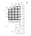
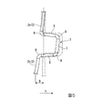
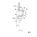
図1に示すように、本実施形態のボイラシステム10は、ボイラ11(第一の設備)と、タービン12(第二の設備)と、ボイラ11とタービン12とを接続する配管2を有する配管構造1と、を備えている。ボイラ11は、ボイラ本体13と、ボイラ本体13を支持するボイラ支持構造体14と、を有している。
[First embodiment]
Hereinafter, a boiler system according to a first embodiment of the present invention will be described in detail with reference to the drawings.
As shown in FIG. 1, the
ボイラ支持構造体14は、基礎15の上に設けられるものであり、支持鉄骨16と、支持鉄骨16を支持する複数の免震装置17と、を有している。
支持鉄骨16は、鉛直方向に延びる複数本の柱18と、水平方向に延びる複数本の梁19と、複数本の鉛直ブレース20と、を組み合わせて構成されている。ボイラ支持構造体14は、支持鉄骨16を構成する柱18の末端部分である柱脚18aを介して基礎15に立設されている。
The
The
ボイラ支持構造体14は、運転中の熱膨張を拘束しないようにするために、最上層の梁19に固定される複数本の吊棒22を介して、ボイラ本体13を支持鉄骨16の頂部から吊り下げている。ボイラ支持構造体14は、ボイラ本体13を水平方向への変位を規制するために、ボイラ本体13と支持鉄骨16の最外周に位置する柱18との間に水平方向に架け渡されるサポート23を介在させている。
In order not to restrain thermal expansion during operation, the
ボイラ支持構造体14は、各々の柱脚18aの基部と基礎15の間に免震装置17を設置している。免震装置17は、例えば、積層ゴムなどによって形成されており、基礎15と支持鉄骨16とを分離し、地震が発生した場合に、支持鉄骨16の振動周期を長周期化することにより、地震による慣性力を低減させ、支持鉄骨16への地震による入力エネルギーを低減する装置である。
免震装置17としては、積層ゴムを利用した装置、すべり材を利用した装置、転がり支承を利用した装置等を採用することができる。免震装置17は、オイルダンパー等のダンパーを有してよい。
In the
As the
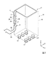
配管構造1は、ボイラ11と、免震装置17によって支持されていないタービン12とを接続する配管2を有している。配管2は、支持鉄骨16の柱18に沿って延在している。配管2は、配管固定具24によって支持鉄骨16の柱18に固定されている。配管2には、例えば、高温(例えば、550℃程度を超える)かつ高圧(例えば、15MPa程度を超える)の蒸気が流れている。
The
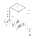
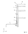
図2に示すように、配管構造1は、配管2と、配管2に設けられた変形吸収部3と、を有している。変形吸収部3は、地震が発生した場合に配管2に生じる変形を吸収する部位である。
なお、以下の説明において、上下方向をZ方向、Z方向に直交する一の水平方向をX方向、Z方向及びX方向に直交する水平方向をY方向とする。
配管2は、水平方向に延在する水平配管25と、上下方向に延在する上下配管26と、を有している。
As shown in FIG. 2, the
In the following description, the vertical direction is the Z direction, one horizontal direction orthogonal to the Z direction is the X direction, and the horizontal direction orthogonal to the Z direction and the X direction is the Y direction.
The
水平配管25は、上下方向において、免震装置17に近い位置に配置されて、基礎15(図1参照)又はタービン12に固定されている。上下配管26は、配管固定具24を介して支持鉄骨16に固定されている。上下配管26と水平配管25とは、配管固定具24の下方にて互いに接続されている。上下配管26は、配管固定具24及び支持鉄骨16を介して免震装置17に支持されている。
地震が発生した場合、上下配管26は、水平方向(X方向とY方向の少なくとも一方)に大きく移動するが、水平配管25は、上下配管26と比較するとほとんど水平方向に移動することはない。
本実施形態の変形吸収部3は、上下配管26における配管固定具24の下方に設けられている。
The
When an earthquake occurs, the upper and
The
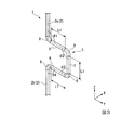
図3に示すように、配管構造1は、円筒形状の配管2と、配管2に設けられた変形吸収部3と、を有している。本実施形態において、配管2は、上下配管26(図2参照)である。
配管2は、ボイラ11側の第一の配管2aと、タービン12側の第二の配管2bと、を有している。第一の配管2a及び第二の配管2bは、同一線上に配置されて上下方向に延在している。第一の配管2aは第二の配管2bの上方に配置されている。変形吸収部3は、第一の配管2aと、第二の配管2bとの間に設けられている。
As shown in FIG. 3, the
The
変形吸収部3は、第一の配管2aの端部(下端)から第一の配管2aと交差する方向に延在する第一交差配管5と、第二の配管2bの端部(上端)から第二の配管2bと交差する方向に延在する第二交差配管6と、第一交差配管5の端部と第二交差配管6の端部とを接続する接続配管7と、を有している。
The
配管2と配管2とは、エルボ8によって接続されている。エルボ8は、湾曲した円筒状の部材であり、本実施形態のエルボ8は、90°の角度で交差する配管同士を接続可能に形成されている。
本実施形態の変形吸収部3において、第一の配管2aと第一交差配管5とのなす角θ1、第一交差配管5と接続配管7とのなす角θ2、接続配管7と第二交差配管6とのなす角θ3、及び第二交差配管6と第二の配管2bとのなす角θ4は、それぞれ略直角(90°)である。
The
In the
配管2及びエルボ8は、例えば、550℃程度を超えるような温度で使用可能な材料によって形成されている。また、配管2及びエルボ8のサイズは、15MPa程度を超えるような圧力に耐えうるサイズが選択されている。
The
次に、本実施形態の変形吸収部3の作用について説明する。
地震が発生すると、配管2が固定されている支持鉄骨16は、X方向、及びY方向に移動する。
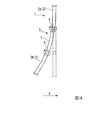
図4に示すように、支持鉄骨16(図2参照)がX方向に移動すると、第一の配管2aがX方向に移動する。一方、第二の配管2bは、ほとんど移動しない。
第一の配管2aのX方向の変位は、変形吸収部3によって吸収される。第一の配管2aのX方向の変位は、第一の配管2a、第二の配管2b、及び接続配管7の曲げ変形と、第一交差配管5、及び第二交差配管6のねじり変形などによって吸収される。
Next, the operation of the
When an earthquake occurs, the
As shown in FIG. 4, when the support steel frame 16 (see FIG. 2) moves in the X direction, the
The displacement in the X direction of the
図5に示すように、支持鉄骨16(図2参照)がY方向に移動すると、第一の配管2aがY方向に移動する。一方、第二の配管2bは、ほとんど移動しない。
第一の配管2aのY方向の変位は、変形吸収部3によって吸収される。第一の配管2aのY方向の変位は、第一の配管2a、第二の配管2b、第一交差配管5、第二交差配管6、接続配管7、及びエルボ8の曲げ変形によって吸収される。
As shown in FIG. 5, when the support steel frame 16 (see FIG. 2) moves in the Y direction, the
The displacement in the Y direction of the
即ち、変形吸収部3は、配管2の曲げ変形及びねじれ変形、エルボ8の曲げ変形等によって、地震時の水平方向の二方向に変位を吸収する。
That is, the
上記実施形態によれば、配管構造1に変形吸収部3を設けることによって、地震により免震装置17によって支持されているボイラ11と、免震装置17によって支持されていないタービン12との間の相対位置が大きく変動した場合においても、配管2にかかる変形を吸収して配管2の変形量を許容することが可能となる。
According to the said embodiment, by providing the deformation |
また、変形吸収部3として、第一の配管2aの端部から第一の配管2aと交差する方向に延在する第一交差配管5と、第二の配管2bの端部から第二の配管2bと交差する方向に延在する第二交差配管6と、第一交差配管5の端部と第二交差配管6の端部とを接続する接続配管7と、を有する構造としたことによって、それぞれの配管の曲げ変形、ねじれ変形によって、配管2に生じる変形を吸収することができる。
Moreover, as the deformation |
また、第一の配管2aと第一交差配管5とのなす角θ1、第一交差配管5と接続配管7とのなす角θ2、接続配管7と第二交差配管6とのなす角θ3、及び第二交差配管6と第二の配管2bとのなす角θ4を、略直角としたことによって、変形吸収部3をコンパクトに形成することができる。
Further, an angle θ1 formed by the
また、本実施形態の配管構造1は、配管2とエルボ8のみによって構成されている。これにより、ユニバーサルジョイント等を用いて変形を吸収する構造と比較して、蒸気の漏れを防ぐことができる。
Moreover, the
〔第二の実施形態〕
以下、本発明の第二の実施形態の配管構造1について図面を参照して詳細に説明する。なお、本実施形態では、上述した第一の実施形態との相違点を中心に述べ、同様の部分についてはその説明を省略する。
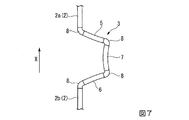
図6に示すように、本実施形態の変形吸収部3は、水平配管25における上下配管26との接続部近傍に設けられている。本実施形態の第一の配管2a及び第二の配管2bは、水平方向に延在している。即ち、変形吸収部3は、上下配管26のみならず、上下配管26との接続部に近接していれば、水平配管25に設けてもよい。
[Second Embodiment]
Hereinafter, the
As shown in FIG. 6, the
図7に示すように、支持鉄骨16(図2参照)がX方向に移動すると、第一の配管2aがX方向に移動する。一方、第二の配管2bは、ほとんど移動しない。
第一の配管2aのX方向の変位は、変形吸収部3によって吸収される。第一の配管2aのX方向の変位は、第一の配管2a、及び第二の配管2bの軸方向の変形と、第一交差配管5、第二交差配管6、接続配管7、及びエルボ8の曲げ変形によって吸収される。
支持鉄骨16(図2参照)のY方向の移動は、図5に示す作用と同様の作用によって吸収される。
As shown in FIG. 7, when the support steel frame 16 (see FIG. 2) moves in the X direction, the
The displacement in the X direction of the
The movement in the Y direction of the supporting steel frame 16 (see FIG. 2) is absorbed by the same action as that shown in FIG.
上記実施形態によれば、水平方向に延在する配管2に変形吸収部3を設けた場合においても、地震によりボイラ11とタービン12との間の相対位置が大きく変動した場合においても、配管2にかかる変形を吸収して配管2の変形量を許容することが可能となる。
According to the above-described embodiment, even when the
〔第三の実施形態〕
以下、本発明の第三の実施形態の配管構造1について図面を参照して詳細に説明する。なお、本実施形態では、上述した第一の実施形態との相違点を中心に述べ、同様の部分についてはその説明を省略する。
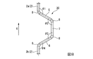
図8に示すように、本実施形態の変形吸収部3Cは、第一の配管2aと第一交差配管5とのなす角θ1、第一交差配管5と接続配管7とのなす角θ2、接続配管7と第二交差配管6とのなす角θ3、及び第二交差配管6と第二の配管2bとのなす角θ4は、それぞれ鈍角(例えば、約120°)である。エルボ8は、この角度に対応する形状を有している。
接続配管7は、第一の配管2a及び第二の配管2bに沿う方向に延在している。即ち、第一の配管2aと第二の配管2bと接続配管7とは互いに平行である。
[Third embodiment]
Hereinafter, the
As shown in FIG. 8, the
The
上記実施形態によれば、配管2を流れる蒸気の圧力損失を低減することができる。
なお、上記実施形態では、各々の配管2をエルボ8を介して接続する構成としたが、これに限ることはない。即ち、エルボ8を用いず、配管2及び変形吸収部3を継ぎ目のない構造としてもよい。これにより、各々の配管2をより滑らかに接続して、より蒸気の圧力損失を低減することができる。
According to the embodiment, the pressure loss of the steam flowing through the
In addition, in the said embodiment, although it was set as the structure which connects each piping 2 via the
〔第四の実施形態〕
以下、本発明の第四の実施形態の配管構造1について図面を参照して詳細に説明する。なお、本実施形態では、上述した第一の実施形態との相違点を中心に述べ、同様の部分についてはその説明を省略する。
図9に示すように、本実施形態の変形吸収部3Dの第一交差配管5、第二交差配管6、及び接続配管7の長さL2は、第一の実施形態の変形吸収部3の第一交差配管5、第二交差配管6、及び接続配管7の長さL1(図3参照)よりも短い。
[Fourth embodiment]
Hereinafter, the
As shown in FIG. 9, the length L2 of the
本実施形態のエルボ8は、第一交差配管5、第二交差配管6、及び接続配管7よりも剛性が低い挙動を示すように形成されている。
本実施形態のエルボ8は、第一交差配管5、第二交差配管6、及び接続配管7よりも薄肉である。本実施形態のエルボ8は、第一の実施形態のエルボ8よりも低剛性である。
上記実施形態によれば、第一の実施形態の変形吸収部3と同じ変位量D(図5も参照)を確保しながら、変形吸収部3をよりコンパクトに形成することができる。
The
The
According to the said embodiment, the deformation |
なお、エルボ8の剛性を下げる手法はこれに限ることはない。例えば、エルボ8の材質を、より、曲がり易い材質に変更してもよい。また、エルボ8の部分のみ、径を小さくしてもよい。さらに、弾塑性挙動も含めて、第一の実施形態のエルボ8よりも低剛性の挙動を示す状態としてもよい。
The method for reducing the rigidity of the
なお、変形吸収部3の大きさ、即ち、第一交差配管5、第二交差配管6、及び接続配管7の長さは、地震応答解析等に基づき算定した配管2の変形量や、ボイラシステム10の規模等に応じて適宜変更することができる。即ち、変形吸収部3を構成する配管2の長さを長くする程、ねじれ変形、曲げ変形を大きくすることができるので、許容変形量を大きくすることができる。
The size of the
また、配管構造1に複数の変形吸収部3を設けてもよい。
また、変形吸収部3の配管2に対する突出方向は、いずれの方向でもよい。図2に示す変形吸収部3は、支持鉄骨16の面に沿う方向に突出しているが、例えば、変形吸収部3を、支持鉄骨16の内側に突出させてもよい。
A plurality of
Moreover, any direction may be sufficient as the protrusion direction with respect to the
また、二つの変形吸収部3を設けて、各々の変形吸収部3の突出方向を逆にしてもよい。即ち、二つの変形吸収部3のうち一の変形吸収部3の交差配管5,6を配管2に略直交する一方向に突出させるとともに、二つの変形吸収部3のうち他の変形吸収部3の交差配管5,6を配管2に略直交する一方向とは異なる方向に突出させてもよい。
Moreover, the two deformation |
〔第五の実施形態〕
以下、本発明の第五の実施形態の配管構造1について図面を参照して詳細に説明する。
本実施形態のボイラシステム10の配管構造1は、支持鉄骨16と配管2との間のクリアランスCが、地震応答解析等に基づき算定した配管2の変形量D2の1.0−1.5倍程度に設定されている。
[Fifth embodiment]
Hereinafter, the
In the
図10に示すように、配管2の変形は、地震応答解析等によって、点線で示すように算定される。
本実施形態の配管固定具24は、配管2と支持鉄骨16(柱18)との間のクリアランスCが、地震応答解析等によって算定された配管2の変形量D2の1.0−1.5倍程度となるように形成されている。
As shown in FIG. 10, the deformation of the
In the
上記実施形態によれば、地震による配管2の水平方向の変形を許容できるとともに、配管2が図10のX方向に最大限に変形した場合においても、確実に配管2と支持鉄骨16との接触を回避することができる。
According to the above embodiment, the horizontal deformation of the
〔第六の実施形態〕
以下、本発明の第六の実施形態の配管構造1について図面を参照して詳細に説明する。なお、本実施形態では、上述した第五の実施形態との相違点を中心に述べ、同様の部分についてはその説明を省略する。
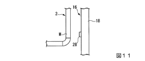
図11に示すように、本実施形態のボイラシステム10は、支持鉄骨16の柱18に緩衝装置28が設けられている。
[Sixth embodiment]
Hereinafter, the
As shown in FIG. 11, in the
緩衝装置28は、例えば、ブロック形状のゴム等によって形成されている。緩衝装置28は、地震応答解析等によって決定された配管2の最大変形部Mの対応箇所に設けられている。
The
上記実施形態によれば、想定外の地震が発生して配管2と支持鉄骨16とが接触する場合においても、配管2の損傷を防止することができる。
なお、緩衝装置28として、減衰機構を有する高減衰ゴムを使用することによって、より接触する際のエネルギーを吸収することができる。
また、緩衝装置28は、配管2側(配管2の最大変形部M)に設けてもよい。
According to the said embodiment, even when the unexpected earthquake generate | occur | produces and the
In addition, the energy at the time of contact can be absorbed by using the high attenuation | damping rubber | gum which has a damping mechanism as the
Further, the
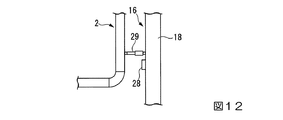
また、図12の第一の例に示すように、緩衝装置28として、オイルダンバー29等の粘性減衰機構を並列して設けてもよい。図12には、ゴム等によって形成されている緩衝装置28も示されているが、配管2と支持鉄骨16との間のクリアランスCに余裕があれば、この緩衝装置28は省略することもできる。
Further, as shown in the first example of FIG. 12, a viscous damping mechanism such as an
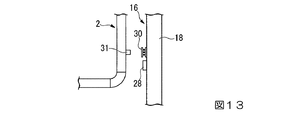
また、図13の第二の例に示すように、緩衝装置28として、鋼材系ダンパー30等(ハニカムダンパなど)の履歴減衰機構を設けてもよい。この場合、配管2側には、鋼材系ダンパー30に荷重を伝達する荷重伝達部材31を設けることが好ましい。
As shown in the second example of FIG. 13, a hysteresis damping mechanism such as a steel damper 30 (honeycomb damper, etc.) may be provided as the
以上、本発明の実施形態について詳細を説明したが、本発明の技術的思想を逸脱しない範囲内において、種々の変更を加えることが可能である。
例えば、上記実施形態では、ボイラとタービンとの間に延在する配管2に変形吸収部3を設けたがこれに限ることはない。即ち、本発明の配管構造は、免震装置を有する支持構造体によって支持されている第一の設備と、免震装置によって支持されていない第二の設備との間を接続する配管に採用することができる。
The embodiment of the present invention has been described in detail above, but various modifications can be made without departing from the technical idea of the present invention.
For example, in the said embodiment, although the deformation |
1 配管構造
2 配管
2a 第一の配管
2b 第二の配管
3 変形吸収部
5 第一交差配管
6 第二交差配管
7 接続配管
8 エルボ
10 ボイラシステム
11 ボイラ(第一の設備)
12 タービン(第二の設備)
13 ボイラ本体
14 ボイラ支持構造体
15 基礎
16 支持鉄骨
17 免震装置
18 柱
19 梁
20 鉛直ブレース
22 吊下げバー
23 サポート
24 配管固定具
25 水平配管
26 上下配管
28 緩衝装置
29 オイルダンバー
30 鋼材系ダンパー
31 荷重伝達部材
C クリアランス
DESCRIPTION OF
12 Turbine (second equipment)
DESCRIPTION OF
Claims (8)
前記配管と、前記配管に設けられた変形吸収部と、を有する配管構造。 A pipe fixed to a support structure having a support steel frame for supporting the first equipment and a seismic isolation device for supporting the support steel, the first equipment and the first structure not supported by the seismic isolation equipment A piping structure having piping for connecting two facilities,
A piping structure having the piping and a deformation absorbing portion provided in the piping.
前記変形吸収部は、前記第一の配管の端部から前記第一の配管と交差する方向に延在する第一交差配管と、
前記第二の配管の端部から前記第二の配管と交差する方向に延在する第二交差配管と、
前記第一交差配管の端部と前記第二交差配管の端部とを接続する接続配管と、を有する請求項1に記載の配管構造。 The pipe has a first pipe on the first equipment side and a second pipe on the second equipment side,
The deformation absorbing portion is a first intersecting pipe extending in a direction intersecting with the first pipe from an end of the first pipe;
A second cross pipe extending from the end of the second pipe in a direction crossing the second pipe;
The piping structure according to claim 1, further comprising a connecting pipe that connects an end of the first intersecting pipe and an end of the second intersecting pipe.
前記接続配管は、前記第一の配管及び前記第二の配管に沿う方向に延在している請求項2に記載の配管構造。 The angle formed by the first pipe and the first cross pipe, and the angle formed by the second cross pipe and the second pipe are obtuse angles,
The pipe structure according to claim 2, wherein the connection pipe extends in a direction along the first pipe and the second pipe.
前記エルボのうち少なくとも一つは、前記配管よりも剛性が低い挙動を示す請求項2から請求項4のいずれか一項に記載の配管構造。 The pipe and the first cross pipe, the first cross pipe and the connection pipe, the connection pipe and the second cross pipe, and the second cross pipe and the pipe are connected by an elbow,
The piping structure according to any one of claims 2 to 4, wherein at least one of the elbows behaves less rigid than the piping.
前記支持鉄骨を支持する免震装置を有する支持構造体と、
前記免震装置によって支持されていない第二の設備と、
上下方向に延在する上下配管と、水平方向に延在する水平配管と、を有する配管を有する請求項1から請求項5のいずれか一項に記載の配管構造と、を有し、
前記変形吸収部は、前記上下配管と前記水平配管との接続部の近傍に設けられているボイラシステム。 A supporting steel frame that supports the first facility;
A support structure having a seismic isolation device for supporting the support steel frame;
A second facility not supported by the seismic isolation device;
The pipe structure according to any one of claims 1 to 5, comprising a pipe having an upper and lower pipe extending in a vertical direction and a horizontal pipe extending in a horizontal direction.
The said deformation | transformation absorption part is a boiler system provided in the vicinity of the connection part of the said upper and lower piping and the said horizontal piping.
Priority Applications (3)
| Application Number | Priority Date | Filing Date | Title |
|---|---|---|---|
| JP2016079791A JP6809807B2 (en) | 2016-04-12 | 2016-04-12 | Piping structure and boiler system |
| PCT/JP2017/014982 WO2017179620A1 (en) | 2016-04-12 | 2017-04-12 | Piping structure and boiler system |
| TW106112132A TWI628374B (en) | 2016-04-12 | 2017-04-12 | Pipe structure and boiler system |
Applications Claiming Priority (1)
| Application Number | Priority Date | Filing Date | Title |
|---|---|---|---|
| JP2016079791A JP6809807B2 (en) | 2016-04-12 | 2016-04-12 | Piping structure and boiler system |
Publications (2)
| Publication Number | Publication Date |
|---|---|
| JP2017190815A true JP2017190815A (en) | 2017-10-19 |
| JP6809807B2 JP6809807B2 (en) | 2021-01-06 |
Family
ID=60042145
Family Applications (1)
| Application Number | Title | Priority Date | Filing Date |
|---|---|---|---|
| JP2016079791A Active JP6809807B2 (en) | 2016-04-12 | 2016-04-12 | Piping structure and boiler system |
Country Status (3)
| Country | Link |
|---|---|
| JP (1) | JP6809807B2 (en) |
| TW (1) | TWI628374B (en) |
| WO (1) | WO2017179620A1 (en) |
Families Citing this family (2)
| Publication number | Priority date | Publication date | Assignee | Title |
|---|---|---|---|---|
| JP6791890B2 (en) * | 2018-01-09 | 2020-11-25 | 三菱パワー株式会社 | Boiler structure |
| JP6766202B2 (en) * | 2019-03-13 | 2020-10-07 | 三菱パワー株式会社 | Boiler device |
Citations (16)
| Publication number | Priority date | Publication date | Assignee | Title |
|---|---|---|---|---|
| JPS56116980A (en) * | 1980-02-15 | 1981-09-14 | Nippon Bulge Ind | Bend for pipings |
| JPS58178583U (en) * | 1982-05-26 | 1983-11-29 | 三菱重工業株式会社 | High temperature and high pressure piping structure |
| JPS5981889U (en) * | 1982-11-24 | 1984-06-02 | 片山 裕 | elbow tube |
| JPS6124889A (en) * | 1984-07-13 | 1986-02-03 | 日揮株式会社 | Piping having double pipe structure |
| JPH062805A (en) * | 1992-06-18 | 1994-01-11 | Babcock Hitachi Kk | Boiler device |
| JPH11280124A (en) * | 1998-03-30 | 1999-10-12 | Nkk Corp | Piping in seismic isolation building |
| JP2000028043A (en) * | 1998-07-13 | 2000-01-25 | Mitsubishi Heavy Ind Ltd | Piping fitting device |
| JP2000304202A (en) * | 1999-04-15 | 2000-11-02 | Babcock Hitachi Kk | Method and structure damping vibration of boiler body |
| JP2000356295A (en) * | 1999-06-16 | 2000-12-26 | Ork:Kk | Base isolated piping system and bellows expansion pipe joint with leg part |
| JP2002031266A (en) * | 2000-07-13 | 2002-01-31 | Fujita Corp | Seismic isolation piping connection structure and its fixed structure |
| JP2004270751A (en) * | 2003-03-06 | 2004-09-30 | Fujita Corp | Piping structure for seismic isolation structures |
| JP2011252755A (en) * | 2010-06-01 | 2011-12-15 | Toshiba Corp | Earthquake scram method and apparatus |
| WO2012133904A1 (en) * | 2011-03-31 | 2012-10-04 | 日揮株式会社 | Sulfur recovery device and sulfur recovery method |
| JP2014240556A (en) * | 2013-06-11 | 2014-12-25 | 株式会社東芝 | Vibration control method, power plant using the same and vibration control system |
| JP2015059685A (en) * | 2013-09-18 | 2015-03-30 | 三菱日立パワーシステムズ株式会社 | Seismic tie for vibration control of boiler, and boiler earthquake-proof structure using the same |
| JP2015121045A (en) * | 2013-12-24 | 2015-07-02 | 三菱日立パワーシステムズ株式会社 | Boiler support structure |
-
2016
- 2016-04-12 JP JP2016079791A patent/JP6809807B2/en active Active
-
2017
- 2017-04-12 TW TW106112132A patent/TWI628374B/en active
- 2017-04-12 WO PCT/JP2017/014982 patent/WO2017179620A1/en not_active Ceased
Patent Citations (16)
| Publication number | Priority date | Publication date | Assignee | Title |
|---|---|---|---|---|
| JPS56116980A (en) * | 1980-02-15 | 1981-09-14 | Nippon Bulge Ind | Bend for pipings |
| JPS58178583U (en) * | 1982-05-26 | 1983-11-29 | 三菱重工業株式会社 | High temperature and high pressure piping structure |
| JPS5981889U (en) * | 1982-11-24 | 1984-06-02 | 片山 裕 | elbow tube |
| JPS6124889A (en) * | 1984-07-13 | 1986-02-03 | 日揮株式会社 | Piping having double pipe structure |
| JPH062805A (en) * | 1992-06-18 | 1994-01-11 | Babcock Hitachi Kk | Boiler device |
| JPH11280124A (en) * | 1998-03-30 | 1999-10-12 | Nkk Corp | Piping in seismic isolation building |
| JP2000028043A (en) * | 1998-07-13 | 2000-01-25 | Mitsubishi Heavy Ind Ltd | Piping fitting device |
| JP2000304202A (en) * | 1999-04-15 | 2000-11-02 | Babcock Hitachi Kk | Method and structure damping vibration of boiler body |
| JP2000356295A (en) * | 1999-06-16 | 2000-12-26 | Ork:Kk | Base isolated piping system and bellows expansion pipe joint with leg part |
| JP2002031266A (en) * | 2000-07-13 | 2002-01-31 | Fujita Corp | Seismic isolation piping connection structure and its fixed structure |
| JP2004270751A (en) * | 2003-03-06 | 2004-09-30 | Fujita Corp | Piping structure for seismic isolation structures |
| JP2011252755A (en) * | 2010-06-01 | 2011-12-15 | Toshiba Corp | Earthquake scram method and apparatus |
| WO2012133904A1 (en) * | 2011-03-31 | 2012-10-04 | 日揮株式会社 | Sulfur recovery device and sulfur recovery method |
| JP2014240556A (en) * | 2013-06-11 | 2014-12-25 | 株式会社東芝 | Vibration control method, power plant using the same and vibration control system |
| JP2015059685A (en) * | 2013-09-18 | 2015-03-30 | 三菱日立パワーシステムズ株式会社 | Seismic tie for vibration control of boiler, and boiler earthquake-proof structure using the same |
| JP2015121045A (en) * | 2013-12-24 | 2015-07-02 | 三菱日立パワーシステムズ株式会社 | Boiler support structure |
Also Published As
| Publication number | Publication date |
|---|---|
| JP6809807B2 (en) | 2021-01-06 |
| WO2017179620A1 (en) | 2017-10-19 |
| TWI628374B (en) | 2018-07-01 |
| TW201736752A (en) | 2017-10-16 |
Similar Documents
| Publication | Publication Date | Title |
|---|---|---|
| KR100756416B1 (en) | Piping Vibration Reduction Device | |
| JP2017517659A (en) | Energy absorber | |
| KR102010316B1 (en) | Ceiling plumbing cradle with multi axis vibration damping function | |
| KR101969079B1 (en) | Ceiling plumbing cradle of double earthquake resistant structure | |
| JP6529557B2 (en) | Earthquake resistant flexible slip joint device | |
| JP6809807B2 (en) | Piping structure and boiler system | |
| CN204785099U (en) | Antivibration support with tensile dish spring of buffering | |
| KR101251196B1 (en) | Blast furnace installation, method for improving earthquake resistance of a blast furnace installation, and linking vibration control apparatus | |
| JP6122744B2 (en) | Seismic tie for boiler vibration control and boiler seismic structure using the same | |
| WO2016143773A1 (en) | Condenser | |
| JP5843732B2 (en) | Seismic tie for boiler vibration control and boiler seismic structure using the same | |
| JP2014145417A (en) | Vibration-proof structure of structure | |
| JP2009293321A (en) | Damping member | |
| JP2022100767A (en) | Vibration control system | |
| KR101663298B1 (en) | Shear panel for restoring original form | |
| TWI744815B (en) | Boiler plant | |
| JP7370827B2 (en) | Piping and its construction method | |
| CN102537579A (en) | Corrugated expansion joint | |
| TW201638544A (en) | boiler | |
| JP5291609B2 (en) | Piping support structure | |
| JP3845140B2 (en) | Structure isolation device | |
| CN121163296B (en) | A heat exchanger unit pipeline support frame | |
| JP2005179936A (en) | Vibration control structure | |
| JP2014156889A (en) | Seismic isolation structure for construction | |
| JP2011246152A (en) | Device for supporting large container, and reactor vessel |
Legal Events
| Date | Code | Title | Description |
|---|---|---|---|
| A521 | Request for written amendment filed |
Free format text: JAPANESE INTERMEDIATE CODE: A821 Effective date: 20160413 |
|
| A625 | Written request for application examination (by other person) |
Free format text: JAPANESE INTERMEDIATE CODE: A625 Effective date: 20180926 |
|
| RD03 | Notification of appointment of power of attorney |
Free format text: JAPANESE INTERMEDIATE CODE: A7423 Effective date: 20181109 |
|
| A131 | Notification of reasons for refusal |
Free format text: JAPANESE INTERMEDIATE CODE: A131 Effective date: 20190611 |
|
| A521 | Request for written amendment filed |
Free format text: JAPANESE INTERMEDIATE CODE: A523 Effective date: 20190809 |
|
| A131 | Notification of reasons for refusal |
Free format text: JAPANESE INTERMEDIATE CODE: A131 Effective date: 20191203 |
|
| A521 | Request for written amendment filed |
Free format text: JAPANESE INTERMEDIATE CODE: A523 Effective date: 20200203 |
|
| A02 | Decision of refusal |
Free format text: JAPANESE INTERMEDIATE CODE: A02 Effective date: 20200623 |
|
| A521 | Request for written amendment filed |
Free format text: JAPANESE INTERMEDIATE CODE: A523 Effective date: 20200923 |
|
| C60 | Trial request (containing other claim documents, opposition documents) |
Free format text: JAPANESE INTERMEDIATE CODE: C60 Effective date: 20200923 |
|
| A911 | Transfer to examiner for re-examination before appeal (zenchi) |
Free format text: JAPANESE INTERMEDIATE CODE: A911 Effective date: 20200930 |
|
| C21 | Notice of transfer of a case for reconsideration by examiners before appeal proceedings |
Free format text: JAPANESE INTERMEDIATE CODE: C21 Effective date: 20201006 |
|
| TRDD | Decision of grant or rejection written | ||
| A01 | Written decision to grant a patent or to grant a registration (utility model) |
Free format text: JAPANESE INTERMEDIATE CODE: A01 Effective date: 20201201 |
|
| A61 | First payment of annual fees (during grant procedure) |
Free format text: JAPANESE INTERMEDIATE CODE: A61 Effective date: 20201210 |
|
| R150 | Certificate of patent or registration of utility model |
Ref document number: 6809807 Country of ref document: JP Free format text: JAPANESE INTERMEDIATE CODE: R150 |