JP2004270751A - Piping structure for base isolation structure - Google Patents
Piping structure for base isolation structure Download PDFInfo
- Publication number
- JP2004270751A JP2004270751A JP2003059486A JP2003059486A JP2004270751A JP 2004270751 A JP2004270751 A JP 2004270751A JP 2003059486 A JP2003059486 A JP 2003059486A JP 2003059486 A JP2003059486 A JP 2003059486A JP 2004270751 A JP2004270751 A JP 2004270751A
- Authority
- JP
- Japan
- Prior art keywords
- joint
- pipe
- piping
- seismic isolation
- coupling
- Prior art date
- Legal status (The legal status is an assumption and is not a legal conclusion. Google has not performed a legal analysis and makes no representation as to the accuracy of the status listed.)
- Pending
Links
Images


Abstract
Description
【0001】
【発明の属する技術分野】
本発明は、構造物の下部構造に対して上部構造が免震装置を介して支持され、前記下部構造に配設された下部構造側配管と、前記上部構造に配設された上部構造側配管とを連結する免震構造物用配管構造に関する。
【0002】
【従来の技術】
構造物の下部構造に対して上部構造が免震装置を介して支持された免震構造物(免震建物や免震床を含む)では、地震時などに、下部構造と上部構造とが水平方向に相対的に変位する。
一方、構造物には上下水道やガスなどの各種設備配管が設けられるが、免震構造物では下部構造と上部構造とが水平方向に相対変位するため、下部構造に配設された下部構造側配管と、上部構造に配設された上部構造側配管とを、前記相対変位を吸収できる構造で連結する必要がある。
このような免震構造物用配管構造として、ユニバーサルジョイントやエルボを用いて下部構造側配管と上部構造側配管とを連結した構造が知られている(例えば、特許文献1参照)。
【0003】
【特許文献1】
特開2002−31266号公報
【0004】
【発明が解決しようとする課題】
しかしながら、この免震構造物用配管構造は、上下方向に延在する配管を必要としており、上下方向に配管スペースが確保できない場合には、採用できない。
本発明は前記事情に鑑み案出されたものであって、本発明の目的は、上下方向に配管スペースを確保することなく配置でき、下部構造と上部構造の相対変位に追従して円滑に変形できる免震構造物用配管構造を提供することにある。
【0005】
【課題を解決するための手段】
前記目的を達成するため本発明は、構造物の下部構造に対して上部構造が免震装置を介して支持され、前記下部構造に下部構造側配管が配設され、前記上部構造に上部構造側配管が配設され、互いに水平方向に離れた下部構造側配管の端部と上部構造側配管の端部とを連結する免震構造物用配管構造であって、前記下部構造側配管の端部に連結された第1継手と、前記上部構造側配管の端部に連結された第2継手と、前記第1継手に一端が連結された第1管体と、前記第2継手に一端が連結された第2管体と、前記第1管体の他端と前記第2管体の他端とを連結する第3継手と、前記第3継手が載置される台車とを有し、前記第1、第2、第3継手はユニバーサルジョイントで構成され、前記第1管体と第2管体は、平面視した場合に、前記第3継手を介して屈曲状に連結され、前記台車は、水平方向に移動可動で前記第3継手の上下高さが調節できるように構成されていることを特徴とする。
本発明の免震構造物用配管構造では、下部構造と上部構造との相対変位時に、この相対変位に追従して第3継手は台車により円滑に迅速に移動し、免震構造物用配管構造が変形する。
【0006】
【発明の実施の形態】
以下、本発明の実施の形態を図面に基づいて詳細に説明する。
まず、第1の実施の形態から説明する。
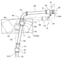
図1は第1の実施の形態に係る配管構造の平面図で、点線は建物と基礎がとが相対的に水平変位していない状態を示し、実線は相対的に水平変位した状態を示し、図2(A)は台車の第1実施例の正面図を示している。
基礎(下部構造)に対して建物(構造物)14が免震装置を介して水平方向に相対変位可能に支持されている。前記基礎に下部構造側配管22が配設され、建物14に上部構造側配管24が配設され、下部構造側配管22の端部22Aと上部構造側配管24の端部24Aとは水平方向に離れている。
実施の形態に係る免震構造物用配管構造12は、このような下部構造側配管22の端部22Aと上部構造側配管24の端部24Aとを連結している。
配管構造12は、下部構造側配管22の端部22Aに連結された第1継手32と、上部構造側配管24の端部24Aに連結された第2継手34と、第1継手32に一端が連結された第1管体36と、第2継手34に一端が連結された第2管体38と、第1管体36の他端と第2管体38の他端とを連結する第3継手40と、第3継手40が載置される台車42とを有している。
【0007】
第1継手32と第2継手34と第3継手40は共に2つの継手部T1、T2を備えた金属製のユニバーサルジョイントである。ここでユニバーサルジョイントとは、2つの継手部T1、T2が相対的に一方の継手部に対して何れの方向にも首振りでき、また、一方の継手部に対して該継手部の軸心を中心に他方の継手が回転できるように連結された継手である。
さらに、本実施の形態では、第1継手32と第2継手34と第3継手40は共に伸縮機能を備えている。すなわち、2つの継手部T1、T2のうちの一方の継手部T2は、例えば、2つの管体が同軸上で液密にあるいは気密にスライド可能に嵌合されることで構成されている。
このような伸縮機能を備えたユニバーサルジョイントは従来公知の市販品であり、例えば、ユーイージョイント株式会社の商品名「U.Eジョイント」を用いることができる。
なお、伸縮機能を備える継手を用いると、水平変位が大きく取れ免震構造物用配管構造12の変形範囲が大きくなる。したがって、免震構造物用配管構造12の変形範囲に問題のない場合には、伸縮機能を備える継手を用いる必要はなく、免震構造物用配管構造12の変形範囲を大きくしたいときに、例えば、第1継手32として伸縮機能を備えた継手を用い、さらに変形範囲を大きくしたいときには、第1継手32および第2継手34として伸縮機能を備えた継手を用い、さらに変形範囲を大きくしたいときには、第1乃至第3継手32、34,40として伸縮機能を備えた継手を用いればよい。
【0008】
第1継手32の継手部T1に下部構造側配管22の端部22Aが連結され、第1継手32の継手部T2に第1管体36の一端が連結されている。
また、第2継手34の継手部T2に上部構造側配管24の端部24Aが連結され、第2継手34の継手部T1に第2管体38の一端が連結されている。
【0009】
第1管体36と第2管体38は共に金属製で直線状に延在している。
そして、第3継手40の継手部T1に第1管体36の他端が連結され、第1管体36は概ね水平方向に延在するように(詳細には、水平方向に延在するように、あるいは、下水管などの場合には水平方向に対してある程度の勾配を持って延在するように)配設されている。
また、第3継手40の継手部T2に金属製のエルボ44の一端が連結され、このエルボ44の他端に第2管体38の他端が連結され、第2管体38は概ね水平方向に延在するように(詳細には、水平方向に延在するように、あるいは、下水管などの場合には水平に対してある程度の勾配を持って延在するように)配設されている。
そして、図1に点線で示すように、建物が動いていない正常時に平面視すると、第1管体36と第2管体38とは、第3継手40とエルボ44を介して、屈曲した状態で連結するように(屈曲角度を持って)配置され、本実施の形態では、ほぼ直交する方向に延在するように(屈曲角度がほぼ90度となるように)配置されている。なお、この屈曲角度は90度に限定されない。
【0010】
台車42は、水平方向に移動可動で第3継手40の重量を支えた状態で第3継手40の上下高さが調節できるように構成されている。なお、厳密には、台車42は第3継手40の重量のみばかりではなく、エルボ44や第1管体36、第2管体38などの重量の一部も支え、ひいては免震構造物用配管構造12の重量を支えている。
台車42は、第3継手40が載置され固定される載置板4202と、載置板4202を上下高さを調節可能に支持する中間板4204と、中間板4204を衝撃吸収可能に支持する基板4206と、基板4206に設けられた移動手段4208とを備えている。
本実施の形態では、基板4206の四隅にそれぞれロッド4210が立設固定されており、このロッド4210が中間板4204、載置版4202の四隅に上下にスライド可能に挿通されている。
【0011】
そして、基板4206と中間板4204における各ロッド4210部分に、それぞれ4枚の皿ばね4212(弾性材)が配設され、基板4206上において中間板4204を上下に移動可能にかつ弾性的に支持するようにしている。なお、基板4206の下方に突出するロッド4210部分の雄ねじに、ロッド4210が上方へ外れてしまうことを防止するためのナット4214が螺合されている。また、中間板4204の上面における各ロッド4210の雄ねじにナット4216が螺合され、ナット4216の下面が中間板4204の上面に当たることで中間板4204に対するロッド4210の上下高さが決定されるように構成されている。
さらに、載置板4202の上面および下面における各ロッド4210の雄ねじにそれぞれナット4218が螺合され、これらナット4218の締め付けによりロッド4210に対する載置板4202の上下高さが決定されるように構成されている。
移動手段4208は、基板4206の下面に取着されたケース4208Aと、ケース4208Aに回転可能に装入された剛球4208Bとで構成され、基礎の上に設置されたステンレスなどの薄い平坦な金属板からなる板部4208Cの上に配設されている。
板部4208Cは、台車42の移動が円滑になされるように設けられたものであり、移動手段4208の構成により、コンクリート製のものや、あるいは合成樹脂製、木製のものを用いることができ、台車42が配置される箇所が平坦な場所である場合には板部4208Cは省略される。
図1の想像線(イ)は、免震構造物用配管構造12の変形に伴う第3継手40の移動範囲、即ち台車42の移動範囲を示しており、板部4208Cはこの移動範囲に対応した大きさ、形状で設けられている。
【0012】
次に、作用について説明する。
地震時などに、免震装置が働いて基礎と建物14との間で水平方向における相対変位が生じると、免震構造物用配管構造12は、図1に点線で示す状態から実線で示す状態に変化する。
ここで、下部構造側配管22の端部22Aを基準として(下部構造側配管22の端部22Aが動かずに)上部構造側配管24の端部24Aが水平方向に移動したと考えると、第1継手32部分においては、継手部T1に対して継手部T2が揺動し、また、継手部T2自体が伸張する。そして、継手部T1に対する継手部T2の揺動と継手部T2自体の伸張により、第1管体36が第1継手32の揺動中心を支点として揺動すると共に前記伸張方向に移動する。
また、第2継手34部分においては、第2継手34自体が水平方向に移動し、継手部T2に対して継手部T1が揺動し、また、継手部T2自体が伸張する。そして、第2継手34自体の移動および継手部T2に対する継手部T1の揺動ならびに継手部T2自体の伸張により、第2管体38が第2継手34の揺動中心を支点として揺動すると共に前記伸張方向に移動する。
このような第1継手32、第2継手34、第1管体36、第2管体38の揺動や移動により、第3継手40部分においては、第3継手40自体が水平面内において移動し、また、エルボ44自体が移動する。さらに、継手部T1と継手部T2とが相対的に揺動し、また、継手部T2自体が伸張する。
そして、以上のようにして第1管体36と第2管体38のなす屈曲角度が変化し、この屈曲角度の変化により基礎と建物14との間の相対変位が吸収され、すなわち、免震構造物用配管構造12が変形することで基礎と建物14との間の相対変位が吸収される。
【0013】
次に、効果について説明する。
本実施の形態の免震構造物用配管構造12は、基礎と建物14との間の相対変位時に、第3継手40の移動は台車42が移動することで円滑に迅速になされ、したがって、第1管体36と第2管体38とがなす屈曲角度も円滑に変化し、免震構造物用配管構造12が円滑に変形できるので、基礎と建物14との間の大きな相対変位を、何処にも無理な力を生じさせることなく免震構造物用配管構造12の変形で吸収でき、免震構造物用配管構造12の耐久性を高める上で有利となる。
そして、免震構造物用配管構造12は、第1継手32、第2継手34、第3継手40に加え、概ね水平方向に延在する第1管体36および第2管体38を含んで構成され、上下方向に延在する配管を必要としないので、上下方向に配管スペースが確保できない箇所に設置することが可能となる。
本実施の形態では、平坦な板部4208Cを設置し、この上で移動手段4208を移動させるようにしたので、第3継手40の移動がより円滑に迅速になされ、免震構造物用配管構造12の耐久性を高める上でより一層有利となる。
また、本実施の形態では、第3継手40を台車42上において皿ばね4212を介して弾性的に支持しているので、基礎と建物14との間の相対変位時に生じる衝撃を皿ばね4212で緩和でき、したがって、第3継手40への衝撃、ひいては免震構造物用配管構造12全体への衝撃を緩和でき、継手自体や管体接合部の損傷を防止する上で有利となり、また、接合部のボルトの緩みなどを防止する上でも有利となり、免震構造物用配管構造12の耐久性を高める上でより一層有利となる。
【0014】
また、免震構造物用配管構造12を構成する部材、部品(第1継手32、第2継手34、第3継手40、エルボ44、第1管体36、第2管体38)は、台車42を除いて全て市販品を用いることができるので、安価に組み立てできてコスト的に有利となり、また、信頼性にも優れる。
また、免震構造物用配管構造12を構成する部材、部品(第1継手32、第2継手34、第3継手40、エルボ44、第1管体36、第2管体38)を、台車42を除いて全て金属製としたので、ゴム製の配管構造に比べ耐久性に優れ、したがって、高温の液体や高圧の液体を通す場合に好適となる。
また、下水管などの場合には、水平方向に対して所定の勾配を持たせて配管しなければならず、現場での勾配調節作業が必要となるが、本実施の形態では、台車42が免震構造物用配管構造12の重量を支えると共に第3継手40の高さ調節機能を備えており、作業員は免震構造物用配管構造12の重量を仮支えすることなく単なるナット4218の弛緩緊締により中間板4204に対する載置板4202の高さを調節することで第3継手40の高さが簡単に調節できるので、現場での勾配調節作業を簡単に行なうことができる。
したがって、特に、第1管体36や第2管体38が太くて重い場合に、これら第1管体36や第2管体38を保持することなく台車42に載置した状態でその勾配調節を行なえるため、現場での勾配調節作業を極めて効率良く行なう上で有利となる。
また、伸縮機能を備えた第1継手32、第2継手34、第3継手40を用いたので、免震構造物用配管構造12を大型化することなく基礎と建物14との間の相対変位に追従して免震構造物用配管構造12がより大きな範囲で円滑に変形でき、したがって、免震構造物用配管構造12のコンパクト化を図る上で有利となる。
【0015】
次に、台車42の第2実施例について説明する。
図2(B)は台車の第2実施例の正面図を示している。なお、以下の説明において、図2(A)の台車42と同様な箇所、部材には同一の符号を付して説明する。
第2実施例の台車42Aでは、移動手段4208の構成が図2(A)の台車42と異なっている。
すなわち、移動手段4208は、基板4206の下面に取着されたキャスター輪4208Dにより構成され、このキャスター輪4208Dは板部4208Cの上で転動するように配設されている。
このような台車42Aを台車42に代えて用いても、免震構造物用配管構造12では前記と同様な効果が奏される。
【0016】
次に、台車42の第3実施例について説明する。
図3(A)は台車の第3実施例の正面図を示している。
第3実施例の台車42Bでは、移動手段4208の構成が図2(A)の台車42と異なっている。
すなわち、移動手段4208は、基板4206の下面に取着された滑り支承4208Eにより構成され、この滑り支承4208Eは金属あるいは合成樹脂製であり、板部4208Cの上で滑動するように配設されている。
このような台車42Bを台車42に代えて用いても、免震構造物用配管構造12では前記と同様な効果が奏される。
【0017】
次に、台車42の第4実施例について説明する。
図3(B)は台車の第4実施例の正面図を示している。
第4実施例の台車42Cでは、皿ばね4212(弾性材)の構成が図3(A)の台車42Dと異なっている。
すなわち、台車42Cでは、弾性材として皿ばね4212の代わりにゴム板4212Aを用いており、ゴム板4212Aは、その下面が基板4206に取着され、その上面が中間板4204に取着されて配設され、ゴム板4212Aにより第3継手40を弾性的に支持し、ゴム板4212Aにより衝撃を緩和するようにしている。
このような台車42Cを台車42に代えて用いても、免震構造物用配管構造12では前記と同様な効果が奏される。
なお、前記の台車の説明では、弾性材として皿ばね4212やゴム板4212Aを用いた場合について説明したが、弾性材としてコイルスプリングなどの他の弾性材を用いてもよい。
【0018】
【発明の効果】
以上説明したように本発明によれば、上下方向に配管スペースが確保できない場合に配置でき、また、下部構造と上部構造との相対変位に追従して円滑に変形できる安価な免震構造物用配管構造が得られる。
【図面の簡単な説明】
【図1】第1の実施の形態に係る配管構造の平面図である。
【図2】(A)は台車の第1実施例の正面図、(B)は台車の第2実施例の正面図である。
【図3】(A)は台車の第3実施例の正面図、(B)は台車の第4実施例の正面図である。
【符号の説明】
12 免震構造物用配管構造
22 下部構造側配管
24 上部構造側配管
32 第1継手
34 第2継手
36 第1管体
38 第2管体
40 第3継手
42 台車[0001]
TECHNICAL FIELD OF THE INVENTION
According to the present invention, an upper structure is supported on a lower structure of a structure via a seismic isolation device, and a lower structure side pipe disposed on the lower structure, and an upper structure side pipe disposed on the upper structure. The present invention relates to a piping structure for a seismic isolation structure that connects the above.
[0002]
[Prior art]
For base-isolated structures (including base-isolated buildings and base-isolated floors) in which the upper structure is supported via seismic isolation devices with respect to the lower structure of the structure, the lower structure and the upper structure are horizontal when an earthquake occurs. Relatively displaced in the direction.
On the other hand, various facilities such as water and sewage and gas are installed in the structure, but in the case of seismic isolation structures, the lower structure and the upper structure are displaced in the horizontal direction relative to each other. It is necessary to connect the pipe and the upper structure side pipe provided in the upper structure by a structure capable of absorbing the relative displacement.
As such a pipe structure for a seismic isolation structure, a structure in which a lower structure side pipe and an upper structure side pipe are connected using a universal joint or an elbow is known (for example, see Patent Document 1).
[0003]
[Patent Document 1]
JP, 2002-31266, A
[Problems to be solved by the invention]
However, this piping structure for a seismic isolation structure requires piping that extends in the vertical direction, and cannot be adopted if piping space cannot be secured in the vertical direction.
The present invention has been devised in view of the above circumstances, and an object of the present invention is to be able to arrange without securing a piping space in a vertical direction, to smoothly deform according to a relative displacement between a lower structure and an upper structure. An object of the present invention is to provide a piping structure for a seismic isolation structure.
[0005]
[Means for Solving the Problems]
In order to achieve the above object, the present invention is directed to an upper structure, wherein an upper structure is supported through a seismic isolation device with respect to a lower structure of a structure, a lower structure side pipe is disposed in the lower structure, and an upper structure side is provided in the upper structure. A pipe structure for a seismic isolation structure, wherein a pipe is provided and connects an end of the lower structure side pipe and an end of the upper structure side pipe which are horizontally separated from each other, wherein the end of the lower structure side pipe A first joint connected to an end of the upper structure side pipe, a first pipe connected to the first joint at one end, and an end connected to the second joint. A second pipe body, a third joint connecting the other end of the first pipe body and the other end of the second pipe body, and a truck on which the third joint is mounted, The first, second, and third joints are configured as universal joints, and the first tube and the second tube are configured such that 3 is connected to via a joint bent manner, the carriage is characterized in that the vertical height of the third joint in the mobile movable in the horizontal direction is configured to be adjusted.
In the piping structure for a base-isolated structure according to the present invention, when the relative displacement between the lower structure and the upper structure is made, the third joint is smoothly and quickly moved by the bogie following the relative displacement. Is deformed.
[0006]
BEST MODE FOR CARRYING OUT THE INVENTION
Hereinafter, embodiments of the present invention will be described in detail with reference to the drawings.
First, the first embodiment will be described.
FIG. 1 is a plan view of the piping structure according to the first embodiment, in which a dotted line indicates a state where the building and the foundation are not relatively horizontally displaced, and a solid line indicates a state where the building and the foundation are relatively horizontally displaced. FIG. 2A shows a front view of the first embodiment of the bogie.
A building (structure) 14 is supported by a base (substructure) via a seismic isolation device so as to be relatively displaceable in the horizontal direction. A lower
In the piping structure 12 for the seismic isolation structure according to the embodiment, the
The pipe structure 12 has a
[0007]
The
Further, in the present embodiment, the
The universal joint having such an expansion and contraction function is a conventionally known commercially available product, and for example, a product name “UE joint” of UEE Joint Co., Ltd. can be used.
When a joint having an expansion and contraction function is used, a large horizontal displacement can be obtained, and the deformation range of the piping structure 12 for the seismic isolation structure becomes large. Therefore, when there is no problem in the deformation range of the seismic isolation structure piping structure 12, it is not necessary to use a joint having an expansion / contraction function, and when it is desired to increase the deformation range of the seismic isolation structure piping structure 12, for example, When using a joint having an expansion and contraction function as the
[0008]
The
Further, an
[0009]
The
The other end of the
Further, one end of a
Then, as shown by a dotted line in FIG. 1, when viewed in a plan view in a normal state where the building is not moving, the
[0010]
The
The
In the present embodiment,
[0011]
Four disc springs 4212 (elastic material) are provided on each
Further, nuts 4218 are screwed into male screws of the
The moving means 4208 is composed of a
The
The imaginary line (a) in FIG. 1 shows the moving range of the third joint 40, that is, the moving range of the
[0012]
Next, the operation will be described.
When the seismic isolation device is activated and a relative displacement occurs in the horizontal direction between the foundation and the
Here, considering that the
In the second joint 34, the second joint 34 itself moves in the horizontal direction, the joint T1 swings with respect to the joint T2, and the joint T2 itself expands. The movement of the second joint 34 itself, the swing of the joint T1 relative to the joint T2, and the extension of the joint T2 itself cause the
Due to the swing and movement of the first joint 32, the second joint 34, the
As described above, the bending angle formed by the
[0013]
Next, effects will be described.
In the seismic isolation structure piping structure 12 of the present embodiment, the third joint 40 is moved smoothly and quickly by the movement of the
Further, the piping structure 12 for the seismic isolation structure includes a
In the present embodiment, the
Further, in the present embodiment, since the third joint 40 is elastically supported on the
[0014]
The members and components (the first joint 32, the second joint 34, the third joint 40, the
In addition, the members and components (the first joint 32, the second joint 34, the third joint 40, the
Further, in the case of a sewer pipe or the like, the pipe must be provided with a predetermined gradient with respect to the horizontal direction, and a gradient adjustment operation on site is required. It has the function of adjusting the height of the third joint 40 while supporting the weight of the seismic isolation structure piping structure 12, and allows the worker to simply use the
Therefore, especially when the
Further, since the first joint 32, the second joint 34, and the third joint 40 having the expansion and contraction function are used, the relative displacement between the foundation and the
[0015]
Next, a second embodiment of the
FIG. 2B shows a front view of the second embodiment of the bogie. In the following description, the same parts and members as those of the
In the
That is, the moving
Even if such a
[0016]
Next, a third embodiment of the
FIG. 3A shows a front view of a third embodiment of the bogie.
In the truck 42B of the third embodiment, the configuration of the moving
That is, the moving
Even if such a trolley 42B is used in place of the
[0017]
Next, a fourth embodiment of the
FIG. 3B shows a front view of the fourth embodiment of the bogie.
In the
That is, in the
Even if such a
In the description of the cart, the case where the
[0018]
【The invention's effect】
As described above, according to the present invention, an inexpensive seismic isolation structure that can be arranged when piping space cannot be secured in the vertical direction and that can smoothly deform following the relative displacement between the lower structure and the upper structure. A piping structure is obtained.
[Brief description of the drawings]
FIG. 1 is a plan view of a piping structure according to a first embodiment.
FIG. 2A is a front view of a first embodiment of the bogie, and FIG. 2B is a front view of a second embodiment of the bogie.
FIG. 3A is a front view of a third embodiment of the trolley, and FIG. 3B is a front view of a fourth embodiment of the trolley.
[Explanation of symbols]
12 Piping structure for
Claims (5)
前記下部構造側配管の端部に連結された第1継手と、
前記上部構造側配管の端部に連結された第2継手と、
前記第1継手に一端が連結された第1管体と、
前記第2継手に一端が連結された第2管体と、
前記第1管体の他端と前記第2管体の他端とを連結する第3継手と、
前記第3継手が載置される台車とを有し、
前記第1、第2、第3継手はユニバーサルジョイントで構成され、
前記第1管体と第2管体は、平面視した場合に、前記第3継手を介して屈曲状に連結され、
前記台車は、水平方向に移動可動で前記第3継手の上下高さが調節できるように構成されている、ことを特徴とする免震構造物用配管構造。An upper structure is supported through a seismic isolation device with respect to a lower structure of the structure, a lower structure-side pipe is provided in the lower structure, and an upper structure-side pipe is provided in the upper structure. A seismic isolation structure piping structure for connecting an end of the separated lower structure side piping and an end of the upper structure side piping,
A first joint connected to an end of the lower structure-side piping;
A second joint connected to an end of the upper structure side pipe;
A first pipe having one end connected to the first joint;
A second pipe having one end connected to the second joint;
A third joint connecting the other end of the first tube and the other end of the second tube;
A truck on which the third joint is mounted,
The first, second and third joints are constituted by universal joints,
The first tube and the second tube are connected in a bent shape via the third joint when viewed in a plan view,
The trolley is configured to be movable in a horizontal direction so that the vertical height of the third joint can be adjusted.
Priority Applications (1)
| Application Number | Priority Date | Filing Date | Title |
|---|---|---|---|
| JP2003059486A JP2004270751A (en) | 2003-03-06 | 2003-03-06 | Piping structure for base isolation structure |
Applications Claiming Priority (1)
| Application Number | Priority Date | Filing Date | Title |
|---|---|---|---|
| JP2003059486A JP2004270751A (en) | 2003-03-06 | 2003-03-06 | Piping structure for base isolation structure |
Publications (1)
| Publication Number | Publication Date |
|---|---|
| JP2004270751A true JP2004270751A (en) | 2004-09-30 |
Family
ID=33122285
Family Applications (1)
| Application Number | Title | Priority Date | Filing Date |
|---|---|---|---|
| JP2003059486A Pending JP2004270751A (en) | 2003-03-06 | 2003-03-06 | Piping structure for base isolation structure |
Country Status (1)
| Country | Link |
|---|---|
| JP (1) | JP2004270751A (en) |
Cited By (7)
| Publication number | Priority date | Publication date | Assignee | Title |
|---|---|---|---|---|
| JP2006077933A (en) * | 2004-09-10 | 2006-03-23 | Ben:Kk | Support system of piping for base-isolated building |
| JP2008025701A (en) * | 2006-07-20 | 2008-02-07 | Ben:Kk | Support system for piping for base-isolated building |
| WO2015097992A1 (en) * | 2013-12-25 | 2015-07-02 | Necプラットフォームズ株式会社 | Cooling system and electronic apparatus |
| KR101732651B1 (en) * | 2015-08-26 | 2017-05-08 | 삼성중공업 주식회사 | Pipe connection module |
| CN108488487A (en) * | 2018-06-01 | 2018-09-04 | 珠海格力电器股份有限公司 | It is a kind of to solve the exceeded pipe fixed block of stress and the air-conditioning system with it |
| CN108612917A (en) * | 2018-05-30 | 2018-10-02 | 华南理工大学 | A kind of vertical vibration damping antidetonation suspension and support based on disk spring |
| CN111746453A (en) * | 2020-07-07 | 2020-10-09 | 中车大同电力机车有限公司 | Connecting device, mining dump truck guardrail structure and mining dump truck |
Citations (1)
| Publication number | Priority date | Publication date | Assignee | Title |
|---|---|---|---|---|
| JP2000356295A (en) * | 1999-06-16 | 2000-12-26 | Ork:Kk | Base isolated piping system and bellows expansion pipe joint with leg part |
-
2003
- 2003-03-06 JP JP2003059486A patent/JP2004270751A/en active Pending
Patent Citations (1)
| Publication number | Priority date | Publication date | Assignee | Title |
|---|---|---|---|---|
| JP2000356295A (en) * | 1999-06-16 | 2000-12-26 | Ork:Kk | Base isolated piping system and bellows expansion pipe joint with leg part |
Cited By (11)
| Publication number | Priority date | Publication date | Assignee | Title |
|---|---|---|---|---|
| JP2006077933A (en) * | 2004-09-10 | 2006-03-23 | Ben:Kk | Support system of piping for base-isolated building |
| JP4549788B2 (en) * | 2004-09-10 | 2010-09-22 | 株式会社ベン | Support system for seismic isolation building piping |
| JP2008025701A (en) * | 2006-07-20 | 2008-02-07 | Ben:Kk | Support system for piping for base-isolated building |
| WO2015097992A1 (en) * | 2013-12-25 | 2015-07-02 | Necプラットフォームズ株式会社 | Cooling system and electronic apparatus |
| JP2015125995A (en) * | 2013-12-25 | 2015-07-06 | Necプラットフォームズ株式会社 | Cooling system and electronic device |
| US10408545B2 (en) | 2013-12-25 | 2019-09-10 | Nec Platforms, Ltd. | Cooling system and electronic equipment |
| KR101732651B1 (en) * | 2015-08-26 | 2017-05-08 | 삼성중공업 주식회사 | Pipe connection module |
| CN108612917A (en) * | 2018-05-30 | 2018-10-02 | 华南理工大学 | A kind of vertical vibration damping antidetonation suspension and support based on disk spring |
| CN108488487A (en) * | 2018-06-01 | 2018-09-04 | 珠海格力电器股份有限公司 | It is a kind of to solve the exceeded pipe fixed block of stress and the air-conditioning system with it |
| CN108488487B (en) * | 2018-06-01 | 2023-09-26 | 珠海格力电器股份有限公司 | Pipe fixing block for solving problem of exceeding stress and air conditioning system with pipe fixing block |
| CN111746453A (en) * | 2020-07-07 | 2020-10-09 | 中车大同电力机车有限公司 | Connecting device, mining dump truck guardrail structure and mining dump truck |
Similar Documents
| Publication | Publication Date | Title |
|---|---|---|
| TW200815650A (en) | Seismically stable flooring | |
| KR20160001755U (en) | Device for protection of vibration | |
| JP2004270751A (en) | Piping structure for base isolation structure | |
| US20180334824A1 (en) | Rigid substructure damping system and method for protecting structures subjected to dynamic forces | |
| KR20140073002A (en) | Brace friction damper | |
| JP4908039B2 (en) | Structure for mounting vibration energy absorber of wooden building | |
| JP2002180693A5 (en) | ||
| RU2624681C2 (en) | Seismic-resistant fixed pipeline support, connection joint of pipeline coil with grillage of pipeline support for seismic-resistant fixed pipeline support and longitudinal damper device for seismic-resistant fixed pipeline support | |
| JP5969829B2 (en) | Stand | |
| JP4216955B2 (en) | Seismic isolation piping system and bellows type expansion joint with legs | |
| JP2005248509A (en) | Damper and vibration isolating structure | |
| JP4878503B2 (en) | Seismic isolation building | |
| WO2017179620A1 (en) | Piping structure and boiler system | |
| JP2598772B2 (en) | Piping support structure | |
| JP6338563B2 (en) | Tower structure | |
| JP2005226423A (en) | Base isolation device | |
| JP2006118689A (en) | Seismic intensity absorbing base for earthquake proofing | |
| JP4919308B1 (en) | Attenuator and installation method | |
| JP2005207179A (en) | Half tension toggle mechanism and building structure | |
| CN206495772U (en) | Large-scale core level main pump test bench location main pump support meanss | |
| JP4549788B2 (en) | Support system for seismic isolation building piping | |
| JP6342709B2 (en) | Base-isolated floor structure and its fixed bearing member | |
| JP2006226517A (en) | Seismic isolation pipe holding construction | |
| JP3205920U (en) | Seismic isolation equipment for buildings and bridges | |
| JP4267097B2 (en) | Piping holding structure for seismic isolation structures |
Legal Events
| Date | Code | Title | Description |
|---|---|---|---|
| A621 | Written request for application examination |
Free format text: JAPANESE INTERMEDIATE CODE: A621 Effective date: 20060125 |
|
| A977 | Report on retrieval |
Free format text: JAPANESE INTERMEDIATE CODE: A971007 Effective date: 20090622 |
|
| A131 | Notification of reasons for refusal |
Free format text: JAPANESE INTERMEDIATE CODE: A131 Effective date: 20090624 |
|
| A02 | Decision of refusal |
Free format text: JAPANESE INTERMEDIATE CODE: A02 Effective date: 20091102 |