JP2017188528A - Semiconductor device - Google Patents
Semiconductor device Download PDFInfo
- Publication number
- JP2017188528A JP2017188528A JP2016075046A JP2016075046A JP2017188528A JP 2017188528 A JP2017188528 A JP 2017188528A JP 2016075046 A JP2016075046 A JP 2016075046A JP 2016075046 A JP2016075046 A JP 2016075046A JP 2017188528 A JP2017188528 A JP 2017188528A
- Authority
- JP
- Japan
- Prior art keywords
- electrode member
- plate
- semiconductor device
- power semiconductor
- substrate
- Prior art date
- Legal status (The legal status is an assumption and is not a legal conclusion. Google has not performed a legal analysis and makes no representation as to the accuracy of the status listed.)
- Pending
Links
Images
Classifications
-
- H—ELECTRICITY
- H01—ELECTRIC ELEMENTS
- H01L—SEMICONDUCTOR DEVICES NOT COVERED BY CLASS H10
- H01L2224/00—Indexing scheme for arrangements for connecting or disconnecting semiconductor or solid-state bodies and methods related thereto as covered by H01L24/00
- H01L2224/01—Means for bonding being attached to, or being formed on, the surface to be connected, e.g. chip-to-package, die-attach, "first-level" interconnects; Manufacturing methods related thereto
- H01L2224/42—Wire connectors; Manufacturing methods related thereto
- H01L2224/44—Structure, shape, material or disposition of the wire connectors prior to the connecting process
- H01L2224/45—Structure, shape, material or disposition of the wire connectors prior to the connecting process of an individual wire connector
- H01L2224/45001—Core members of the connector
- H01L2224/45099—Material
- H01L2224/451—Material with a principal constituent of the material being a metal or a metalloid, e.g. boron (B), silicon (Si), germanium (Ge), arsenic (As), antimony (Sb), tellurium (Te) and polonium (Po), and alloys thereof
- H01L2224/45117—Material with a principal constituent of the material being a metal or a metalloid, e.g. boron (B), silicon (Si), germanium (Ge), arsenic (As), antimony (Sb), tellurium (Te) and polonium (Po), and alloys thereof the principal constituent melting at a temperature of greater than or equal to 400°C and less than 950°C
- H01L2224/45124—Aluminium (Al) as principal constituent
-
- H—ELECTRICITY
- H01—ELECTRIC ELEMENTS
- H01L—SEMICONDUCTOR DEVICES NOT COVERED BY CLASS H10
- H01L2224/00—Indexing scheme for arrangements for connecting or disconnecting semiconductor or solid-state bodies and methods related thereto as covered by H01L24/00
- H01L2224/01—Means for bonding being attached to, or being formed on, the surface to be connected, e.g. chip-to-package, die-attach, "first-level" interconnects; Manufacturing methods related thereto
- H01L2224/42—Wire connectors; Manufacturing methods related thereto
- H01L2224/44—Structure, shape, material or disposition of the wire connectors prior to the connecting process
- H01L2224/45—Structure, shape, material or disposition of the wire connectors prior to the connecting process of an individual wire connector
- H01L2224/45001—Core members of the connector
- H01L2224/45099—Material
- H01L2224/451—Material with a principal constituent of the material being a metal or a metalloid, e.g. boron (B), silicon (Si), germanium (Ge), arsenic (As), antimony (Sb), tellurium (Te) and polonium (Po), and alloys thereof
- H01L2224/45138—Material with a principal constituent of the material being a metal or a metalloid, e.g. boron (B), silicon (Si), germanium (Ge), arsenic (As), antimony (Sb), tellurium (Te) and polonium (Po), and alloys thereof the principal constituent melting at a temperature of greater than or equal to 950°C and less than 1550°C
- H01L2224/45147—Copper (Cu) as principal constituent
-
- H—ELECTRICITY
- H01—ELECTRIC ELEMENTS
- H01L—SEMICONDUCTOR DEVICES NOT COVERED BY CLASS H10
- H01L2224/00—Indexing scheme for arrangements for connecting or disconnecting semiconductor or solid-state bodies and methods related thereto as covered by H01L24/00
- H01L2224/01—Means for bonding being attached to, or being formed on, the surface to be connected, e.g. chip-to-package, die-attach, "first-level" interconnects; Manufacturing methods related thereto
- H01L2224/42—Wire connectors; Manufacturing methods related thereto
- H01L2224/44—Structure, shape, material or disposition of the wire connectors prior to the connecting process
- H01L2224/45—Structure, shape, material or disposition of the wire connectors prior to the connecting process of an individual wire connector
- H01L2224/4554—Coating
- H01L2224/45565—Single coating layer
-
- H—ELECTRICITY
- H01—ELECTRIC ELEMENTS
- H01L—SEMICONDUCTOR DEVICES NOT COVERED BY CLASS H10
- H01L2224/00—Indexing scheme for arrangements for connecting or disconnecting semiconductor or solid-state bodies and methods related thereto as covered by H01L24/00
- H01L2224/01—Means for bonding being attached to, or being formed on, the surface to be connected, e.g. chip-to-package, die-attach, "first-level" interconnects; Manufacturing methods related thereto
- H01L2224/42—Wire connectors; Manufacturing methods related thereto
- H01L2224/44—Structure, shape, material or disposition of the wire connectors prior to the connecting process
- H01L2224/45—Structure, shape, material or disposition of the wire connectors prior to the connecting process of an individual wire connector
- H01L2224/4554—Coating
- H01L2224/45599—Material
- H01L2224/456—Material with a principal constituent of the material being a metal or a metalloid, e.g. boron (B), silicon (Si), germanium (Ge), arsenic (As), antimony (Sb), tellurium (Te) and polonium (Po), and alloys thereof
- H01L2224/45663—Material with a principal constituent of the material being a metal or a metalloid, e.g. boron (B), silicon (Si), germanium (Ge), arsenic (As), antimony (Sb), tellurium (Te) and polonium (Po), and alloys thereof the principal constituent melting at a temperature of greater than 1550°C
- H01L2224/45664—Palladium (Pd) as principal constituent
-
- H—ELECTRICITY
- H01—ELECTRIC ELEMENTS
- H01L—SEMICONDUCTOR DEVICES NOT COVERED BY CLASS H10
- H01L2224/00—Indexing scheme for arrangements for connecting or disconnecting semiconductor or solid-state bodies and methods related thereto as covered by H01L24/00
- H01L2224/01—Means for bonding being attached to, or being formed on, the surface to be connected, e.g. chip-to-package, die-attach, "first-level" interconnects; Manufacturing methods related thereto
- H01L2224/42—Wire connectors; Manufacturing methods related thereto
- H01L2224/47—Structure, shape, material or disposition of the wire connectors after the connecting process
- H01L2224/48—Structure, shape, material or disposition of the wire connectors after the connecting process of an individual wire connector
- H01L2224/4805—Shape
- H01L2224/4809—Loop shape
- H01L2224/48091—Arched
-
- H—ELECTRICITY
- H01—ELECTRIC ELEMENTS
- H01L—SEMICONDUCTOR DEVICES NOT COVERED BY CLASS H10
- H01L2224/00—Indexing scheme for arrangements for connecting or disconnecting semiconductor or solid-state bodies and methods related thereto as covered by H01L24/00
- H01L2224/01—Means for bonding being attached to, or being formed on, the surface to be connected, e.g. chip-to-package, die-attach, "first-level" interconnects; Manufacturing methods related thereto
- H01L2224/42—Wire connectors; Manufacturing methods related thereto
- H01L2224/47—Structure, shape, material or disposition of the wire connectors after the connecting process
- H01L2224/48—Structure, shape, material or disposition of the wire connectors after the connecting process of an individual wire connector
- H01L2224/484—Connecting portions
- H01L2224/4846—Connecting portions with multiple bonds on the same bonding area
-
- H—ELECTRICITY
- H01—ELECTRIC ELEMENTS
- H01L—SEMICONDUCTOR DEVICES NOT COVERED BY CLASS H10
- H01L2224/00—Indexing scheme for arrangements for connecting or disconnecting semiconductor or solid-state bodies and methods related thereto as covered by H01L24/00
- H01L2224/73—Means for bonding being of different types provided for in two or more of groups H01L2224/10, H01L2224/18, H01L2224/26, H01L2224/34, H01L2224/42, H01L2224/50, H01L2224/63, H01L2224/71
- H01L2224/732—Location after the connecting process
- H01L2224/73251—Location after the connecting process on different surfaces
- H01L2224/73265—Layer and wire connectors
-
- H—ELECTRICITY
- H01—ELECTRIC ELEMENTS
- H01L—SEMICONDUCTOR DEVICES NOT COVERED BY CLASS H10
- H01L2924/00—Indexing scheme for arrangements or methods for connecting or disconnecting semiconductor or solid-state bodies as covered by H01L24/00
- H01L2924/15—Details of package parts other than the semiconductor or other solid state devices to be connected
- H01L2924/181—Encapsulation
Landscapes
- Cooling Or The Like Of Semiconductors Or Solid State Devices (AREA)
Abstract
Description
本発明は、半導体装置、特に電力半導体装置に関する。 The present invention relates to a semiconductor device, and more particularly to a power semiconductor device.
電気鉄道車両及び風力発電設備等の大電力を扱う電力半導体装置における内部配線として、板状の電極部材を用いることが多い。その理由は、アルミニウムなどを用いたワイヤボンド配線に比べて板状電極部材は、電流密度を高く設定できるためである。板状電極部材と基板の導体部との接続には、一般的にソルダペーストを用いたはんだ付けが用いられる。ソルダペーストには、被接合材表面の酸化被膜を除去する還元剤、ディスペンスなどで供給し易いように粘度調整するための増粘剤、及び揮発成分などが含まれており、はんだ付けの際の熱により、これらの成分は気体となり蒸発する。このような気体がはんだ中に残留することで空隙であるボイドとなり、接合部近傍に残留する。接合部にボイドが存在した場合には接合面積が減少し、接合部の接続信頼性が低下する場合がある。 In many cases, plate-like electrode members are used as internal wiring in power semiconductor devices that handle large amounts of power such as electric railway vehicles and wind power generation facilities. The reason is that the plate-like electrode member can set the current density higher than the wire bond wiring using aluminum or the like. In general, soldering using a solder paste is used to connect the plate electrode member and the conductor portion of the substrate. The solder paste contains a reducing agent that removes the oxide film on the surface of the material to be joined, a thickener for adjusting the viscosity so that it can be easily supplied by dispensing, and a volatile component. With heat, these components become gas and evaporate. When such gas remains in the solder, it becomes a void which is a void and remains in the vicinity of the joint. When a void exists in a junction part, a junction area reduces and the connection reliability of a junction part may fall.
電力半導体装置のはんだ接合部における接続信頼性の低下を防ぐ方法が特許文献1及び特許文献2に提案されている。
上記特許文献1では、はんだ接合部に対応して板状電極部材(端子)に突起を設けることで接合材厚を一定にして接続信頼性の確保を図っている。しかしながら、突起により端子におけるみかけの板厚が増加し、熱応力が増大して、接続信頼性を担保することができない。また、上記特許文献2では、板状電極部材(リード)に曲げ形状部分を設けることで、はんだフィレット高さを制御して接続信頼性の確保を意図している。しかしながらこの方法では、はんだ厚さを制御することはできない。
In the above-mentioned
本発明は、上述したような問題点を解決するためになされたもので、半導体装置内の板状電極部材における接合部の接続信頼性を、従来に比べて向上可能な半導体装置を提供することを目的とする。 The present invention has been made to solve the above-described problems, and provides a semiconductor device capable of improving the connection reliability of a joint portion in a plate-like electrode member in a semiconductor device as compared with the conventional one. With the goal.
上記目的を達成するため、本発明は以下のように構成する。
即ち、本発明の一態様における半導体装置は、半導体素子実装用の基板であって、対向する第1主面と第2主面とにそれぞれ導体パターンを有する基板と、対向する第1面及び第2面を有し、上記第1主面における導体パターンに上記第2面を接合した接合領域を有する板状電極部材と、を備え、上記板状電極部材は、上記第1面に凹部を上記第2面に凸部をそれぞれ有し、この凹部及び凸部は、当該板状電極部材の厚み方向において上記接合領域を上記第1面及び上記第2面に投影した投影領域に位置することを特徴とする。
In order to achieve the above object, the present invention is configured as follows.
That is, a semiconductor device according to one embodiment of the present invention is a substrate for mounting a semiconductor element, which includes a substrate having a conductor pattern on each of a first main surface and a second main surface facing each other, and a first surface and a second surface facing each other. And a plate-like electrode member having a joining region obtained by joining the second surface to the conductor pattern on the first main surface, and the plate-like electrode member has a recess on the first surface. Each of the second surfaces has a convex portion, and the concave portion and the convex portion are located in a projection region obtained by projecting the joining region onto the first surface and the second surface in the thickness direction of the plate-like electrode member. Features.
本発明の一態様における半導体装置によれば、板状電極部材の第2面に凸部を設け、この第2面を基板の導体パターンに接合することから、凸部により、接合材厚さを一定以上にすることができ、接合材内にボイドが発生した場合でも接合材外へ排出することができる。また、凸部によって、接合材が薄くなる領域に対応して凹部を設けることで、凸部のみを設ける場合に比べて、見かけの板状電極部材の厚さを小さくすることができる。よって、板状電極部材と接合材との間に生じる熱応力を低減することができ、接合部の熱疲労寿命、ひいては接続信頼性を、従来に比べて向上することができる。 According to the semiconductor device of one embodiment of the present invention, the convex portion is provided on the second surface of the plate-like electrode member, and the second surface is joined to the conductor pattern of the substrate. Even if a void is generated in the bonding material, it can be discharged out of the bonding material. Further, by providing the concave portions corresponding to the regions where the bonding material is thinned by the convex portions, the apparent plate-like electrode member can be made thinner than when only the convex portions are provided. Therefore, the thermal stress generated between the plate-like electrode member and the bonding material can be reduced, and the thermal fatigue life of the bonded portion and thus the connection reliability can be improved as compared with the conventional case.
実施形態である半導体装置について、図を参照しながら以下に説明する。尚、各図において、同一又は同様の構成部分については同じ符号を付している。また、以下の説明が不必要に冗長になるのを避け当業者の理解を容易にするため、既によく知られた事項の詳細説明及び実質的に同一の構成に対する重複説明を省略する場合がある。また、以下の説明及び添付図面の内容は、特許請求の範囲に記載の主題を限定することを意図するものではない。 A semiconductor device according to an embodiment will be described below with reference to the drawings. In each figure, the same or similar components are denoted by the same reference numerals. In addition, in order to avoid the following description from becoming unnecessarily redundant and to facilitate understanding by those skilled in the art, a detailed description of already well-known matters and a duplicate description of substantially the same configuration may be omitted. . Further, the contents of the following description and the accompanying drawings are not intended to limit the subject matter described in the claims.
また以下の各実施の形態では、大電流を扱うことに起因してより大きな応力が接合部に作用することから、より高い接続信頼性が要求される電力半導体装置を例に採る。しかしながら各実施形態における構成は、電力半導体装置用に限定するものではなく、通常電流を扱う一般的な半導体装置にも適用可能である。 Further, in each of the following embodiments, since a larger stress acts on the joint due to handling a large current, a power semiconductor device that requires higher connection reliability is taken as an example. However, the configuration in each embodiment is not limited to a power semiconductor device, but can be applied to a general semiconductor device that handles a normal current.
実施の形態1.
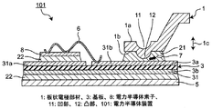
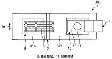
図1A及び図1B(総称して図1と記す場合もある)には、本実施の形態1における電力半導体装置101の構成の一例が示されている。当該電力半導体装置101は、基本的構成部分として、板状電極部材1と、絶縁材料で形成された基板3と、電力半導体素子8とを有する。ここで金属製で短冊状の板状電極部材1は、対向する第1面1aと第2面1bとを有する。基板3は、対向する第1主面3aと第2主面3bとを有し、第1主面3a及び第2主面3bにはそれぞれ導体パターン31が設けられている。第1主面3a側には電力半導体装置8及び板状電極部材1が、第2主面3b側にはヒートスプレッダ5が接合される。
1A and 1B (also collectively referred to as FIG. 1) show an example of the configuration of the
以下に説明する各実施の形態において、板状電極部材1は次の部材を意味する。即ち、電力半導体装置の外面には、モータなどの外部機器と接続するための端子が設けられるが、板状電極部材1は、この端子に該当する。また板状電極部材1は、一般的に通電によるジュール発熱を考慮して、上記端子となる部分から、電力半導体装置内における、以下で説明する導体パターン31bとの接合部(接合領域15)に至るまでの間、同じ断面積を有する部材であることが多い。また、上記端子となる部分から接合部までの間で、電磁ノイズ対策などのため、分岐する場合もある。このような分岐を有する形態では、分岐部分から上記接合部までの間が板状電極部材1に相当する。尚、後述の実施の形態4,5では、板状電極部材1に切欠き部を設けた構成を説明するが、この切欠き部は上記接合部に位置することから、上記分岐部分に該当するものではない。
In each embodiment described below, the plate-
また詳細後述するが、板状電極部材1は、特徴的構成部分の一つとして本実施の形態1では、第1面1aに凹部11を、第2面1bに凸部12をそれぞれ有する。
As will be described in detail later, the plate-
電力半導体装置8は、例えばIGBT(絶縁ゲートバイポーラトランジスタ)あるいはダイオードなどが相当し、ダイボンド工程において一般的にはリフロー工法などを用いて、導体パターン31における一方の導体パターン31aに第2接合材22によって接合され、電気的接続が図られる。第2接合材22は、例えばはんだである。また、この接合によって、電力半導体装置8とヒートスプレッダ5とは一体化され、電力半導体装置8がスイッチング動作する際に生じる熱を、ヒートスプレッダ5を介してさらに放熱器へと逃がすことが可能となる。
The
また電力半導体装置8における電極は、例えばアルミニウムワイヤ6などを用いたワイヤボンディングにより、第1主面3aに存在する、導体パターン31における他方の導体パターン31bに電気的接続される。
またこの導体パターン31bには、板状電極部材1が第1接合材21によって接合される。よって板状電極部材1は、導体パターン31bとの接合領域15を有する。尚、第1接合材21は、一例として下記のように、主にはんだ合金から成るソルダペーストである。
The electrode in the
In addition, the
上述したように端子となる板状電極部材1の接続工程では、まずディスペンサーなどを用いて第1接合材21が導体パターン31bの必要箇所に供給される。このとき第1接合材21上に板状電極部材1を配置する。次に、ホットプレートなどを用いて、ヒートスプレッダ5から入熱させて、第1接合材21及び板状電極部材1を加熱する。第1接合材21として、例えば、主にはんだ合金から成るソルダペーストを用いた場合、ソルダペーストは、はんだ合金、及び、高級カルボン酸あるいはアルコール類を成分とするフラックスであり、加熱により、第1接合材21から揮発成分などが気体に変化し始める。さらに加熱を続けることで、第1接合材21のはんだ合金が溶融し、導体パターン31b及び板状電極部材1へと濡れ広がり、両者間の接合が完了する。そして第1接合材21が凝固するタイミングでボイド7が発生し、接合部近傍に残留する場合がある。
As described above, in the connection process of the plate-
本実施の形態1では、上述のように、板状電極部材1は、第1接合材21にて導体パターン31bと接合される接合領域15、並びに、その第1面1aに凹部11、及び第2面1bに凸部12をそれぞれ有する。この凹部11及び凸部12は、板状電極部材1の厚み方向1cにおいて接合領域15を第1面1a及び第2面1bに投影した投影領域17内に位置する。また図1Aに示すように、板状電極部材1の厚み方向1cにおいて、板状電極部材1の厚さに対する凹部11の深さ及び凸部12の高さは、板状電極部材1の厚さと同等もしくは小さくしている。
In the first embodiment, as described above, the plate-
上述のように板状電極部材1の第2面1bに凸部12を設け、この第2面1bを基板3の導体パターン31bに接合することから、凸部12により、第1接合材21の厚さを一定以上にすることができ、第1接合材21内にボイド7が発生した場合でも、第1接合材21外へ排出することができる。したがって、板状電極部材1と導体パターン31bとの間に十分な接合面積を確保することができ、従来に比べて接合部の接続信頼性を高めることができる。
As described above, the
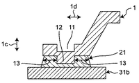
図7A及び図7B(総称して、図7と記す場合もある。)に示すように、凸部12の外周面側に存在する第1接合材21の部材延在方向1dにおける長さ13は、凸部12を設けることで、板状電極部材1の凹凸加工前における長さと同等もしくは小さくなっている。このことで、凸部12及び長さ13に対応した板状電極部材1の領域に凹部11を設けることで、凸部12のみを備える場合よりも、板状電極部材1の見かけの厚さを薄くすることができる。よって板状電極部材1の剛性が下がることから、板状電極部材1と第1接合材21との間に生じる熱応力を低減することができ、第1接合材21の熱疲労寿命を延ばすことができる。したがって、接続信頼性の高い電力半導体装置101を得ることが可能となる。
As shown in FIG. 7A and FIG. 7B (generally referred to as FIG. 7), the
さらに凸部12及び長さ13に対応した板状電極部材1の領域では、第1接合材21の厚みが板状電極部材1と同等もしくは薄くなっているので、第1接合材21及び導体パターン31bで発生した熱を効率よく大気中へ放出することも可能になる。
Further, in the region of the
また、凹部11及び凸部12は、板状電極部材1の抜き加工を行う際に、一体的に成型することができるため、凸部12のみを設ける場合よりも、生産性が高い。
凸部12について、本実施の形態1では一例として半円球状としたが、これに限定するものではなく、バスタブ形状、角柱形状などの他の形状でもかまわない。
また凸部12の半円球状の直径は、一例として板状電極部材1の板厚程度であるが、これに限定するものではない。
Moreover, since the recessed
In the first embodiment, the
Moreover, although the hemispherical diameter of the
また、第1接合材21に作用する応力及び歪みを考慮すると、第1接合材21が薄くなる領域、つまり図1Aにおいて凹部11を第1接合材21に投影した部分は、できるだけ小さい方が良く、凹部11及び凸部12の板状電極部材1における幅方向1e(図7B)の寸法は、凹部11及び凸部12の形状に関わらず、一例として板状電極部材1の幅を超えないものである。
また、凹部11及び凸部12を設ける場所は、第1接合材21内であれば、どこに備えても良い。
また、ジュール発熱の観点から、凸部12の突出高さ、及び凹部11の凹み深さは、それぞれ板状電極部材1の、一例として板厚の50%以下であるが、これに限定するものではない。
また、第1接合材21として、はんだを用いる場合、はんだが濡れ広がる際に、隣接するワイヤボンド部などに付着することが懸念される場合には、はんだ接合部外周にソルダレジストを設けても良い。ソルダレジストとしては、エポキシ樹脂、アルミニウム、はんだの濡れない金属及びその酸化物、例えば酸化銅など、を用いることができる。
In consideration of the stress and strain acting on the
Further, the place where the
From the viewpoint of Joule heat generation, the protruding height of the
Further, when solder is used as the
第1接合材21は、Sn−Sb系はんだ、Sn−Cu系はんだ、Sn−Ag系はんだ、Sn−Ag−Cu系はんだ、Sn−Ag−In系はんだ、Sn−Zn系はんだ、Sn−Bi系はんだ、又は、Sn−Pb系はんだのいずれか、もしくは、これらを組み合わせたものを用いることができる。これらのはんだの場合、再溶融が可能という利点がある。
また、第1接合材21は、一例として、第2接合材22と同じ融点か、より低い融点のはんだである。これにより、第1接合材21のはんだ付け中に、第2接合材22が再溶融することが無くなるため、はんだボールの発生によるパターンショート、あるいは電力半導体素子の耐圧低下が発生しないという効果がある。
導体パターン31a,31bとしては銅、アルミニウム、Ni/Auフラッシュめっき銅、Niめっき銅、Niめっきアルミニウム、Suめっき銅を用いることができる。
絶縁材料から形成される基板3として、紙フェノール、紙エポキシ、ガラスエポキシ、テフロン(登録商標)、ポリイミド、セラミック(AlN、Al2O3、Si3N4)を用いることができる。
ヒートスプレッダ5としては、アルミニウム、銅、アルミニウム含浸SiC、マグネシウム含浸SiCを用いることができる。また、ヒートスプレッダ5、及びヒートスプレッダ5上の第2接合材22は省略しても良い。
また、ワイヤ6としては、アルミニウム、アルミニウム合金、銅、パラジウム被覆銅などを用いることができる。
The
Moreover, the
As the
As the
As the
As the
実施の形態2.
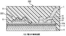
本実施の形態2では、図1Aに示す電力半導体装置101においてケース付け工程まで完了したものに、図2に示すように封止材9を注入した電力半導体装置102が示される。電力半導体装置102におけるその他の構成は、実施の形態1における電力半導体装置101に同じであり、その説明は省略する。
Embodiment 2. FIG.
In the second embodiment, the
ここで封止材9として、シリコーン系封止材を用いることで、その誘電率により、封止材9が無い場合よりも絶縁耐電圧が高い電力半導体装置を得ることができるという効果がある。
また、封止材9としてエポキシ系封止材を用いた場合には、第1接合材21及び第2接合材22における接合力を封止材9による接着力によって補強することができる。言い換えると、板状電極部材1における接合領域15の周囲をエポキシ系封止材によって機械的に補強することができ、接合領域15に発生する応力及び歪みを低減し、はんだの疲労寿命を延ばすことができる。よって、より接続信頼性の高い電力半導体装置102を得ることができるという効果がある。
Here, by using a silicone-based sealing material as the sealing material 9, there is an effect that a power semiconductor device having a higher withstand voltage than that without the sealing material 9 can be obtained due to its dielectric constant.
Further, when an epoxy-based sealing material is used as the sealing material 9, the bonding force in the
また、実施の形態1における電力半導体装置101にて説明した効果及び変形例については、当該実施の形態2における電力半導体装置102においても同様に得ることができ、また適用可能である。
Further, the effects and modifications described in the
実施の形態3.
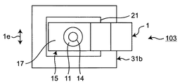
本実施の形態3では、実施の形態1の電力半導体装置101に対して図3A及び図3B(総称して、図3と記す場合もある。)に示すように、板状電極部材1の凹部11と凸部12とを、板状電極部材1の厚み方向1cに貫通する穴14をさらに設けた電力半導体装置103が示される。尚、図3では、板状電極部材1に関する構成部分のみを抜粋して図示している。また、電力半導体装置103におけるその他の構成は、実施の形態1における電力半導体装置101に同じであり、その説明は省略する。
In the third embodiment, as shown in FIGS. 3A and 3B (generally referred to as FIG. 3 in general) with respect to the
穴14を設けることで、第1接合材21内で発生したボイド7を穴14を通じて、第1接合材21の外へ排出することが可能になる。したがって、接合部における接合面積は確保され、より接続信頼性の高い電力半導体装置103を得ることが可能になるという効果がある。
By providing the
また、本実施の形態3の電力半導体装置103においても、図4に示すように封止材9にて封止した構成を採ることができる。このように封止した場合、実施の形態2で説明した、封止材9の接着による補強効果が得られると共に、本実施の形態3ではさらに、穴14内にも封止材9が進入することによるアンカー効果により、封止材9の接着寿命を延ばすことができ、より補強効果を増すことができる。したがって、より接続信頼性の高い電力半導体装置103を得ることができるという効果がある。
Further, the
穴14は、凹部11及び凸部12を板状電極部材1から抜き加工を行う際に、凹部11及び凸部12と一体的に成型することができるため、追加の工数を必要とせずに成型可能である。また穴14の形状は、一例として円形状であるが、成型の制約上、角柱形状など他の形状としてもかまわない。また、円形状の穴14の場合、穴14の直径の最小値は、一例として板状電極部材1の板厚程度である。また、穴14の位置は、一例として、凹部11及び凸部12の重心を通る位置であるが、これに限定するものではない。
The
また、穴14を設けることで、余剰な第1接合材21を穴14内へ吸収することができる。また、第1接合材21に、はんだを用いた場合、穴14内に形成されたフィレット形状を穴14の上から見ることができ、板状電極部材1と、はんだとの濡れ状態を目視で検査することが可能となる。よって外観検査を利用して、接合状態に不具合がある製品を排除することができるという効果もある。
Further, by providing the
さらに、穴14内に形成されるフィレットによって接合部に作用する応力が分散され、はんだ接合部の応力及び歪みを低減することができる。この点からも、より接続信頼性の高い電力半導体装置103を得ることができるという効果が得られる。
Further, the stress acting on the joint is dispersed by the fillet formed in the
また穴14を設けることで、導体パターン31bと封止材9とを直接接着することができ、はんだ接合部を補強すると共に、その周辺部へ応力を分散することも可能になる。よって、はんだ接合部の応力及び歪みを低減することができる。さらにこの点からも、より接続信頼性の高い電力半導体装置103を得ることができるという効果が得られる。
Also, by providing the
また、実施の形態1における電力半導体装置101にて説明した効果及び変形例について、当該実施の形態3における電力半導体装置103においても同様に得ることができ、また適用可能である。
Further, the effects and modifications described in the
実施の形態4.
本実施の形態4では、板状電極部材1における凹部11及び凸部12の変形例を有する電力半導体装置が示されている。
本実施の形態4では、図5A及び図5B(総称して図5と記す場合もある。)に示す電力半導体装置104において、板状電極部材1は、舌片41を接合領域15に有する。詳しく説明すると、板状電極部材1の端部から板状電極部材1の延在方向に沿って2本の切り込みを入れ、切り込み間の切欠き片を導体パターン31bの方へ折り曲げることで、舌片41を形成する。この舌片41を導体パターン31bに接触させた状態で板状電極部材1と導体パターン31bとの接合を行う。よって、舌片41が上述の凸部12に相当し、舌片41に成った切欠き部分が上述の穴14に相当する。
尚、電力半導体装置104におけるその他の構成は、実施の形態1における電力半導体装置101に同じであり、その説明は省略する。
Embodiment 4 FIG.
In the fourth embodiment, a power semiconductor device having a modification of the
In the fourth embodiment, in the
The rest of the configuration of
本実施の形態4におけるこのような構成によれば、舌片41の折り曲げにより形成された折り曲げ領域41aからボイド7を放出することができ、かつ、舌片41の折り曲げ量によって第1接合材21の厚さを制御することができる。よって、第1接合材21の厚さを一定以上にすることができる。
According to such a configuration in the fourth embodiment, the
また、折り曲げ領域41aは、切欠き部分とみなすことができるので、第1接合材21として、はんだ等、濡れ性を有する材料を用いた場合、実施の形態3で説明したように、フィレット長を長くすることができる。これにより板状電極部材1と第1接合材21との間に生じる熱応力を低減し、第1接合材21の熱疲労寿命を延ばすことができる。したがって、より接続信頼性の高い電力半導体装置104を得ることができるという効果がある。
Further, since the
舌片41及び折り曲げ領域41aの大きさの一例としては、図5に示すように、高さH=0.1mm、折り曲げ領域41aの長さL1=3mm、舌片41と導体パターン31bとの部材延在方向1dにおける長さL2、及び、幅方向1eにおける領域41aの幅W1は、共に板状電極部材1の厚さ程度である。しかしながら、これらの各寸法は、上述の寸法に限定するものではない。
As an example of the size of the
このように本実施の形態4の電力半導体装置104では、板状電極部材1において、はんだ接合部以外の部分の断面積に対して、はんだ接合部内の板状電極部材1の断面積は、同じ、あるいは小さくすることができる。その結果、はんだ接合部における角部の応力及び歪みを低減することができ、より接続信頼性の高い電力半導体装置104を得ることができるという効果がある。尚、この効果は、以下に説明する実施の形態5でも得ることができる。
As described above, in the
また、実施の形態1における電力半導体装置101にて説明した効果及び変形例について、当該実施の形態4における電力半導体装置104においても同様に得ることができ、また適用可能である。
Further, the effects and modifications described in the
実施の形態5.
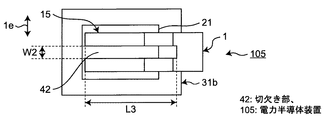
本実施の形態5の電力半導体装置も、実施の形態4と同様に板状電極部材1における凹部11及び凸部12の変形例に関する。図6A及び図6B(総称して図6と記す場合もある。)に示す本実施の形態5の電力半導体装置105では、板状電極部材1は、実施の形態4で説明した舌片41を有さず、折り曲げ領域41aに相当する切欠き部42のみを有する。尚、電力半導体装置105におけるその他の構成は、実施の形態1における電力半導体装置101に同じであり、その説明は省略する。
The power semiconductor device according to the fifth embodiment also relates to a modification of the
切欠き部42は、板状電極部材1の端部から板状電極部材1の部材延在方向1dに沿って延在する凹部であり、本実施の形態5では、板状電極部材1において一箇所に存在する。その結果、本実施の形態5では、板状電極部材1の端部は二股形状であるが、複数の切欠き部42を設けて三つ股以上としてもよい。即ち、板状電極部材1と第1接合材21との接合面積が大きくなるほど、ボイド7が発生し易くなり、さらに各材料の角部の応力及び歪みが大きくなる。よって板状電極部材1と第1接合材21との接続信頼性が低下してしまう。これを防止するために、板状電極部材1の端部つまり接合部に切欠き部42を形成し、接合部を複数に分割する。
このように構成することで、接合部の角部の応力及び歪みを低減することができ、より接続信頼性の高い電力半導体装置105を得ることができるという効果が得られる。
The
With this configuration, it is possible to reduce the stress and distortion at the corners of the joint, and the
ここで、部材延在方向1dにおける切欠き部42の長さL3について、図6Bでは第1接合材21との接合領域15を超えて延在する形態を示すが、接合領域15と同じ、あるいは接合領域15よりも小さい長さであってもよい。
Here, regarding the length L3 of the
実施の形態4、5では、舌片41及び折り曲げ領域41a、並びに、切欠き部42は、部材延在方向1dに沿う板状電極部材1の中心線に対して対称になるように形成しているが、非対称になるように形成した場合でも、上述と同様の効果が得られる。
In the fourth and fifth embodiments, the
板状電極部材1に電流を流したときの板状電極部材1の過熱を防止するため、通電に伴う発熱と、大気中及び封止材9への放熱とのバランスを取る必要がある。一般的には、板状電極部材からの発熱量を制御するため、板状電極部材の延在方向において板状電極部材の断面積は、一定に設定している。一方、上述したように実施の形態4、5では、板状電極部材1において、はんだ接合部以外の部分の断面積に対して、はんだ接合部内の板状電極部材1の断面積を同じあるいは小さくしている。
この構成に関して、実施の形態4,5においても、実施の形態1〜3における構成と同様に、板状電極部材1と導体パターン31bとの接合部に対応して、厚み方向1cにおいて基板3及びヒートスプレッダ5を配置している。よって、板状電極部材1の接合部近傍では、大気中及び封止材9への放熱量よりも、基板3及びヒートスプレッダ5への放熱量が大きくなる。その結果、実施の形態4,5においても、板状電極部材1が過熱することは無い。
In order to prevent overheating of the plate-
With respect to this configuration, in the fourth and fifth embodiments, similarly to the configurations in the first to third embodiments, the
また、実施の形態1における電力半導体装置101にて説明した効果及び変形例について、当該実施の形態5における電力半導体装置105においても同様に得ることができ、また適用可能である。
Further, the effects and modifications described in the
また、上述した各実施の形態を組み合わせた構成を採ることも可能であり、また、異なる実施の形態に示される構成部分同士を組み合わせることも可能である。 Moreover, it is also possible to take the structure which combined each embodiment mentioned above, and it is also possible to combine the component parts shown by different embodiment.
1 板状電極部材、1a 第1面、1b 第2面、3 基板、
3a 第1主面、3b 第2主面、8 電力半導体素子、9 封止材、
11 凹部、12 凸部、14 穴、15 接合領域、17 投影領域、
31b 導体パターン、41 舌片、42 切欠き部、
101〜105 電力半導体装置。
1 plate electrode member, 1a first surface, 1b second surface, 3 substrate,
3a 1st main surface, 3b 2nd main surface, 8 electric power semiconductor element, 9 sealing material,
11 concave portion, 12 convex portion, 14 holes, 15 joint region, 17 projection region,
31b Conductor pattern, 41 Tongue piece, 42 Notch,
101-105 Power semiconductor device.
Claims (5)
対向する第1面及び第2面を有し、上記第1主面における導体パターンに上記第2面を接合した接合領域を有する板状電極部材と、を備え、
上記板状電極部材は、上記第1面に凹部を上記第2面に凸部をそれぞれ有し、この凹部及び凸部は、当該板状電極部材の厚み方向において上記接合領域を上記第1面及び上記第2面に投影した投影領域に位置する、
ことを特徴とする半導体装置。 A substrate for mounting a semiconductor element, the substrate having a conductive pattern on each of the first main surface and the second main surface facing each other;
A plate-like electrode member having a first surface and a second surface facing each other, and having a joining region obtained by joining the second surface to the conductor pattern on the first main surface,
The plate-like electrode member has a concave portion on the first surface and a convex portion on the second surface, and the concave portion and the convex portion serve as the first surface in the thickness direction of the plate-like electrode member. And located in the projection area projected on the second surface,
A semiconductor device.
対向する第1面及び第2面を有し、上記第1主面における導体パターンに上記第2面を接合した接合領域を有する板状電極部材と、を備え、
上記板状電極部材は、当該板状電極部材の端部に設けた複数の切り込み間に位置する切欠き片を折り曲げた状態の舌片を上記接合領域に有する、
ことを特徴とする半導体装置。 A substrate for mounting a semiconductor element, the substrate having a conductive pattern on each of the first main surface and the second main surface facing each other;
A plate-like electrode member having a first surface and a second surface facing each other, and having a joining region obtained by joining the second surface to the conductor pattern on the first main surface,
The plate-like electrode member has a tongue piece in a state in which a notch piece located between a plurality of cuts provided at an end of the plate-like electrode member is bent in the joining region.
A semiconductor device.
対向する第1面及び第2面を有し、上記第1主面における導体パターンに上記第2面を接合した接合領域を有する板状電極部材と、を備え、
上記板状電極部材は、上記接合領域に切欠き部を有し、かつ、上記接合領域における当該板状電極部材の断面積が接合領域外における当該板状電極部材の断面積に比して同じあるいは小さい、
ことを特徴とする半導体装置。 A substrate for mounting a semiconductor element, the substrate having a conductive pattern on each of the first main surface and the second main surface facing each other;
A plate-like electrode member having a first surface and a second surface facing each other, and having a joining region obtained by joining the second surface to the conductor pattern on the first main surface,
The plate-like electrode member has a notch in the joining region, and the cross-sectional area of the plate-like electrode member in the joining region is the same as the cross-sectional area of the plate-like electrode member outside the joining region Or small,
A semiconductor device.
Priority Applications (1)
| Application Number | Priority Date | Filing Date | Title |
|---|---|---|---|
| JP2016075046A JP2017188528A (en) | 2016-04-04 | 2016-04-04 | Semiconductor device |
Applications Claiming Priority (1)
| Application Number | Priority Date | Filing Date | Title |
|---|---|---|---|
| JP2016075046A JP2017188528A (en) | 2016-04-04 | 2016-04-04 | Semiconductor device |
Publications (2)
| Publication Number | Publication Date |
|---|---|
| JP2017188528A true JP2017188528A (en) | 2017-10-12 |
| JP2017188528A5 JP2017188528A5 (en) | 2019-05-09 |
Family
ID=60045716
Family Applications (1)
| Application Number | Title | Priority Date | Filing Date |
|---|---|---|---|
| JP2016075046A Pending JP2017188528A (en) | 2016-04-04 | 2016-04-04 | Semiconductor device |
Country Status (1)
| Country | Link |
|---|---|
| JP (1) | JP2017188528A (en) |
Cited By (2)
| Publication number | Priority date | Publication date | Assignee | Title |
|---|---|---|---|---|
| JPWO2021100199A1 (en) * | 2019-11-22 | 2021-05-27 | ||
| JP2022048877A (en) * | 2020-09-15 | 2022-03-28 | 株式会社東芝 | Semiconductor device |
Citations (4)
| Publication number | Priority date | Publication date | Assignee | Title |
|---|---|---|---|---|
| JPH01156560U (en) * | 1988-04-21 | 1989-10-27 | ||
| JPH05315490A (en) * | 1992-05-07 | 1993-11-26 | Fuji Electric Co Ltd | Semiconductor element |
| JP2007096004A (en) * | 2005-09-29 | 2007-04-12 | Toshiba Corp | Semiconductor device |
| WO2015107871A1 (en) * | 2014-01-15 | 2015-07-23 | パナソニックIpマネジメント株式会社 | Semiconductor device |
-
2016
- 2016-04-04 JP JP2016075046A patent/JP2017188528A/en active Pending
Patent Citations (4)
| Publication number | Priority date | Publication date | Assignee | Title |
|---|---|---|---|---|
| JPH01156560U (en) * | 1988-04-21 | 1989-10-27 | ||
| JPH05315490A (en) * | 1992-05-07 | 1993-11-26 | Fuji Electric Co Ltd | Semiconductor element |
| JP2007096004A (en) * | 2005-09-29 | 2007-04-12 | Toshiba Corp | Semiconductor device |
| WO2015107871A1 (en) * | 2014-01-15 | 2015-07-23 | パナソニックIpマネジメント株式会社 | Semiconductor device |
Cited By (5)
| Publication number | Priority date | Publication date | Assignee | Title |
|---|---|---|---|---|
| JPWO2021100199A1 (en) * | 2019-11-22 | 2021-05-27 | ||
| WO2021100199A1 (en) * | 2019-11-22 | 2021-05-27 | 三菱電機株式会社 | Semiconductor device, method for producing same, and electric power conversion device |
| JP7237192B2 (en) | 2019-11-22 | 2023-03-10 | 三菱電機株式会社 | Semiconductor device, manufacturing method thereof, and power conversion device |
| JP2022048877A (en) * | 2020-09-15 | 2022-03-28 | 株式会社東芝 | Semiconductor device |
| JP7438071B2 (en) | 2020-09-15 | 2024-02-26 | 株式会社東芝 | semiconductor equipment |
Similar Documents
| Publication | Publication Date | Title |
|---|---|---|
| US9418918B2 (en) | Lead for connection to a semiconductor device | |
| JP4924411B2 (en) | Power semiconductor device | |
| US9966327B2 (en) | Lead frame, semiconductor device, method for manufacturing lead frame, and method for manufacturing semiconductor device | |
| JP4438489B2 (en) | Semiconductor device | |
| CN109314063B (en) | Power semiconductor device | |
| US9935074B2 (en) | Semiconductor device and method for manufacturing same | |
| WO2019220788A1 (en) | Semiconductor device | |
| JP2006134990A (en) | Semiconductor apparatus | |
| JP2007184525A (en) | Electronic apparatus | |
| US9076782B2 (en) | Semiconductor device and method of manufacturing same | |
| US20170117212A1 (en) | Semiconductor device | |
| JP2011009410A (en) | Semiconductor module | |
| JP6260566B2 (en) | Circuit structure | |
| JP4557804B2 (en) | Semiconductor device and manufacturing method thereof | |
| JP2017050441A (en) | Semiconductor device | |
| JP5732880B2 (en) | Semiconductor device and manufacturing method thereof | |
| JP2017199809A (en) | Power semiconductor device | |
| JP2017188528A (en) | Semiconductor device | |
| JP5579148B2 (en) | Power semiconductor device | |
| JP2011023748A (en) | Electronic apparatus | |
| JP2016181607A (en) | Semiconductor device and manufacturing method of the same | |
| US11295997B2 (en) | Semiconductor device manufacturing method and semiconductor device | |
| JP5734493B2 (en) | Power semiconductor device | |
| KR101561920B1 (en) | Semiconductor package | |
| JP5418654B2 (en) | Semiconductor device |
Legal Events
| Date | Code | Title | Description |
|---|---|---|---|
| A521 | Request for written amendment filed |
Free format text: JAPANESE INTERMEDIATE CODE: A523 Effective date: 20190326 |
|
| A621 | Written request for application examination |
Free format text: JAPANESE INTERMEDIATE CODE: A621 Effective date: 20190326 |
|
| A977 | Report on retrieval |
Free format text: JAPANESE INTERMEDIATE CODE: A971007 Effective date: 20191226 |
|
| A131 | Notification of reasons for refusal |
Free format text: JAPANESE INTERMEDIATE CODE: A131 Effective date: 20200121 |
|
| A02 | Decision of refusal |
Free format text: JAPANESE INTERMEDIATE CODE: A02 Effective date: 20200804 |
