JP2017179997A - Column-beam joint structure and construction method therefor - Google Patents
Column-beam joint structure and construction method therefor Download PDFInfo
- Publication number
- JP2017179997A JP2017179997A JP2016071794A JP2016071794A JP2017179997A JP 2017179997 A JP2017179997 A JP 2017179997A JP 2016071794 A JP2016071794 A JP 2016071794A JP 2016071794 A JP2016071794 A JP 2016071794A JP 2017179997 A JP2017179997 A JP 2017179997A
- Authority
- JP
- Japan
- Prior art keywords
- column
- joint
- bar
- shear
- reinforcement
- Prior art date
- Legal status (The legal status is an assumption and is not a legal conclusion. Google has not performed a legal analysis and makes no representation as to the accuracy of the status listed.)
- Granted
Links
Images


Abstract
Description
本開示は、柱梁接合構造及びその施工方法、特に、柱梁接合部に機械式継手を有する柱梁接合構造及びその施工方法に関する。 The present disclosure relates to a column beam joint structure and a construction method thereof, and particularly to a column beam joint structure having a mechanical joint in a column beam joint portion and a construction method thereof.
図9は、従来の鉄筋コンクリート造の建物における柱梁接合構造1の正面図であり、コンクリート部分は外面を線で示すが、内部のコンクリートは省略して示している。柱2は、柱主筋3及び帯筋4を有し、梁5は、梁主筋6及びあばら筋7を有する。柱梁接合部8では、柱主筋3と梁主筋6とが互いに交差するように配置され、せん断補強筋9は、帯筋4と平行に配置される。
FIG. 9 is a front view of a beam-column joint structure 1 in a conventional reinforced concrete building, and the concrete portion is shown with lines on the outer surface, but the inner concrete is omitted. The
また、梁主筋を機械式継手で連結する工法が提案されている。例えば、特許文献1では、平面視で十字方向に延在する梁と柱との接合部において、一方向の梁主筋を連結する機械式継手を、他方向に延在する梁主筋を連結する機械式継手に対して上下に重ならない位置に配置することが提案されている。また、特許文献1に記載の柱梁接合構造では、接合部のせん断補強筋は、帯筋と平行に配置されている。特許文献1によると、このような構造では、機械式継手が上下に重なる場合に比べて、梁主筋の上下方向へのずれが小さく、梁の有効せいが大きくなる。 In addition, a method of connecting beam main bars with mechanical joints has been proposed. For example, in Patent Document 1, a mechanical joint that connects beam main bars in one direction at a joint between a beam and a column that extends in a cross direction in a plan view, and a machine that connects beam main bars that extend in the other direction. It has been proposed to arrange it at a position that does not overlap vertically with respect to the type joint. Moreover, in the beam-column joint structure described in Patent Document 1, the shear reinforcement bars at the joint are arranged in parallel with the band bars. According to Patent Document 1, in such a structure, the vertical displacement of the beam main bars is small and the effective beam is large, compared to the case where the mechanical joints overlap vertically.
一方、柱梁接合部ではなく、梁の中間位置において、高強度鉄筋からなる梁主筋と普通鉄筋からなる梁主筋とを機械式継手で連結することが特許文献2において提案されている。特許文献2に記載の柱梁接合構造では、接合部のせん断補強筋は、あばら筋と平行に配置されている。特許文献2に記載の梁は、高強度鉄筋からなる梁主筋及びあばら筋を含む梁構成ユニットと、普通鉄筋からなる梁主筋及びあばら筋を含む梁構成ユニットとを、別々に組み立てた後、クレーン等を用いて配置し、機械式継手で連結することで構築される。特許文献2によると、このような構造によって梁構成ユニットが小型化され、施工作業性が向上する。
On the other hand,
一般に、柱梁架構は、大地震が発生したときでも柱の降伏が防止されるように、梁降伏型で設計される。従って、大地震時には、柱主筋は降伏せずに梁主筋が柱近傍の梁端部において降伏するため、柱梁接合部内の梁主筋に大きなひずみが生じる。例えば、図9に示すように、柱梁接合部における梁主筋が通し配筋(鉄筋がそのまま通っている状態)の場合、梁主筋とコンクリートとの間の付着が切れて、梁主筋はコンクリートをすべりながら伸びることになる。このとき、梁の幅方向において互いに隣接する梁主筋間の間隔は比較的小さいため、互いに隣接する梁主筋間に水平方向のひび割れが生じる。 In general, the column beam structure is designed in a beam yield type so that the yield of the column is prevented even when a large earthquake occurs. Therefore, at the time of a large earthquake, the column main reinforcement does not yield, and the beam main reinforcement yields at the beam end near the column, resulting in a large strain in the beam main reinforcement in the column beam joint. For example, as shown in FIG. 9, when the beam reinforcement at the beam-column joint is through (reinforcing the reinforcement), the bond between the beam reinforcement and the concrete breaks, and the beam reinforcement is made of concrete. It will grow while sliding. At this time, since the distance between adjacent beam main bars in the beam width direction is relatively small, horizontal cracks occur between adjacent beam main bars.
さらに、機械式継手が柱梁接合部内に配置されている場合には、機械式継手の小口部分がコンクリートを押すこと、径の大きな機械式継手では隣接する機械式継手との間隔が梁主筋間の間隔よりもさらに小さくなること、及び、表面積が大きいため付着抵抗が大きくなること等から、柱梁接合部内のコンクリートの損傷が大きくなるおそれがある。 In addition, when the mechanical joint is located in the beam-column joint, the edge of the mechanical joint pushes the concrete, and in the case of a mechanical joint with a large diameter, the distance between adjacent mechanical joints is between the beam main bars. There is a possibility that damage to the concrete in the beam-column joint is increased because it is further smaller than the distance between the two and the adhesion resistance increases due to the large surface area.
本発明は、このような背景に鑑みてなされたもので、柱梁接合部内に機械式継手を有する柱梁接合構造において、梁主筋が降伏したときに生じるコンクリートの損傷を抑制することを目的とする。 The present invention has been made in view of such a background, and an object of the present invention is to suppress damage to concrete caused when a beam main bar yields in a beam-column joint structure having a mechanical joint in a beam-column joint. To do.
本発明の少なくともいくつかの実施形態は、所定の方向(X方向)に延在する梁(13a)の梁主筋(18a)を連結する機械式継手(21)を柱梁接合部(14)内に含む柱梁接合構造(11)であって、前記梁の梁主筋は、少なくとも上下2段に配置されており、前記柱梁接合部を補強するせん断補強筋は、柱(12)において前記所定の方向における最も外側に配置された柱主筋(15)の間に配置され、かつ上下方向に延在する部分を有するあばら方向せん断補強筋(22)を含むことを特徴とする。ここで、「上下方向」とは、鉛直方向、又は鉛直方向において最も整合する位置にある上段側の梁主筋と下段側の梁主筋とを結ぶ方向を言い、他の部材との取り合いの関係によって厳密な上下方向に対して傾いていたり、曲がったりしている場合を含む。 In at least some embodiments of the present invention, a mechanical joint (21) connecting a beam main bar (18a) of a beam (13a) extending in a predetermined direction (X direction) is provided in a column beam joint (14). The beam main reinforcement of the beam is arranged in at least two upper and lower stages, and the shear reinforcement reinforcing the beam-to-column connection is provided in the column (12). It is characterized in that it includes a rib-direction shear reinforcement bar (22) having a portion extending between the column main bars (15) arranged on the outermost side in the direction of and extending in the vertical direction. Here, the “vertical direction” means the direction connecting the beam main bar on the upper side and the beam main bar on the lower side in the vertical direction or the most aligned position in the vertical direction, and depending on the relationship with other members Including the case of tilting or bending with respect to the exact vertical direction.
この構成によれば、上下に配置された梁主筋が、大地震時に柱のゆれによって互いにX方向に力を受けても、あばら方向せん断補強筋が上下方向に延在しているため、その力に抵抗し、梁主筋及び機械式継手とコンクリートとの付着が切れて梁主筋及び機械式継手がコンクリートに対してすべることを抑制し、それによりコンクリートが損傷することを抑制できる。 According to this structure, even if the main beam bars arranged vertically are subjected to forces in the X direction due to the shaking of the columns in the event of a large earthquake, the shear shear reinforcement bars extend in the vertical direction. It is possible to prevent the beam main bar and the mechanical joint from being attached to the concrete and to prevent the beam main bar and the mechanical joint from sliding against the concrete, thereby preventing the concrete from being damaged.
本発明の少なくともいくつかの実施形態は、上記構成において、前記梁は、プレキャストコンクリート製であることを特徴とする。 At least some embodiments of the present invention are characterized in that, in the above configuration, the beam is made of precast concrete.
この構成によれば、施工現場での作業性を向上させることができるとともに、工期を短縮できる。 According to this configuration, workability at the construction site can be improved and the work period can be shortened.
本発明の少なくともいくつかの実施形態は、上記構成において、前記せん断補強筋は、上下に配置された前記梁主筋の間に配置され、かつ前記柱の主筋の延在方向に直交する平面に平行に配置された帯方向せん断補強筋をさらに含むことを特徴とする。 In at least some embodiments of the present invention, in the above configuration, the shear reinforcement bars are arranged between the beam main bars arranged above and below and parallel to a plane perpendicular to the extending direction of the main bars of the column. And further comprising a band-direction shear reinforcement.
この構成によれば、接合部において、柱の帯筋と平行な方向にもせん断補強筋を配置することになり、せん断耐力をさらに向上させることができる。 According to this configuration, the shear reinforcement bars are also arranged in the joint portion in the direction parallel to the column strips, and the shear strength can be further improved.
本発明の少なくともいくつかの実施形態は、柱(12)を立設するステップと、少なくとも上下2段に配置された梁主筋(18a)を含むプレキャストコンクリート製の2つの第1梁部材(25a)を、前記柱の両側に直線状となるように、かつ各々の一端側が前記柱との接合部(14)に位置するように配置するステップと、前記柱の上方に配置された機械式継手(21)によって前記2つの第1梁部材の前記梁主筋を互いに連結するステップと、前記接合部にせん断補強筋を設置するステップと、前記接合部に、コンクリートを打設するステップとを備え、前記せん断補強筋を設置するステップは、上下方向に延在する部分を有して前記梁主筋に直交する平面に平行な方向に延在するべきあばら方向せん断補強筋(22)を前記梁主筋又は前記機械式継手に当接又は近接するべき位置に組み付けるステップを含むことを特徴とする。 At least some embodiments of the present invention include two first beam members (25a) made of precast concrete that include the step of erecting a column (12) and beam main bars (18a) arranged in at least two upper and lower stages. Are disposed so that both sides of the column are linear and one end side of each column is positioned at a joint (14) with the column, and a mechanical joint ( 21) connecting the beam main bars of the two first beam members to each other, installing a shear reinforcement bar at the joint, and placing concrete at the joint, In the step of installing the shear reinforcement, the rib-direction shear reinforcement (22) having a portion extending in the vertical direction and extending in a direction parallel to a plane perpendicular to the beam principal reinforcement is provided with the beam reinforcement or the beam reinforcement. Characterized in that it comprises a step of assembling a position to be in contact with or close to the mechanical coupling.
この構成によれば、上述の作用効果を備える柱梁接合構造を施工することができる。 According to this structure, a column beam joint structure provided with the above-mentioned effect can be constructed.
本発明の少なくともいくつかの実施形態は、上記構成において、前記あばら方向せん断補強筋を組み付けるステップは、前記梁部材を配置するステップよりも前に行われることを特徴とする。 At least some embodiments of the present invention are characterized in that, in the above configuration, the step of assembling the loose shear reinforcement is performed before the step of arranging the beam member.
この構成によれば、比較的狭いスペースに設置されるあばら方向せん断補強筋を工場又は施工現場の地上等で組み付けられるため、作業効率を向上させることができる。 According to this configuration, since the loose shear reinforcing bars installed in a relatively narrow space can be assembled on the ground of a factory or a construction site, work efficiency can be improved.
本発明の少なくともいくつかの実施形態は、上記構成において、前記第1梁部材に交差する方向に配置される第2梁部材(25b)を前記柱に対して設置するステップをさらに備え、該第2梁部材を配置するステップは前記第1梁部材を配置するステップの前に行われ、前記接合部における前記第2梁部材の梁主筋(18b)は通し配筋であり、前記あばら方向せん断補強筋を組み付けるステップは、前記第2梁部材を配置するステップよりも前に、前記第2梁部材に対して行われることを特徴とする。 At least some embodiments of the present invention may further include the step of installing a second beam member (25b) arranged in a direction intersecting the first beam member with respect to the column in the above configuration. The step of arranging the two beam members is performed before the step of arranging the first beam member, and the main beam (18b) of the second beam member at the joint is a through bar, and the shear shear reinforcement is performed. The step of assembling the line is performed on the second beam member before the step of arranging the second beam member.
この構成によれば、接合部で梁が交差する場合であっても、あばら方向せん断補強筋を工場又は施工現場の地上等で組みつけられ、作業効率を向上させることができる。 According to this configuration, even when the beams cross at the joint, the loose shear reinforcement bars can be assembled on the ground of the factory or construction site, and work efficiency can be improved.
柱梁接合部内に機械式継手を有する柱梁接合構造において、梁主筋が降伏したときに生じるコンクリートの損傷を抑制することができる。 In the beam-column joint structure having a mechanical joint in the beam-column joint, it is possible to suppress damage to the concrete that occurs when the beam main bar yields.
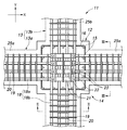
以下、図面を参照しながら、本発明の実施形態を説明する。まず、図1〜図3を参照して本発明の実施形態に係る柱梁接合構造11を説明する。図1〜図3では、コンクリートの外面を線で示すが、内部のコンクリートの図示は省略している。以下、図1の紙面の左右方向をX方向、図1の紙面の上下方向をY方向、図1の紙面に直交する方向をZ方向と記す。X方向及びY方向は、互いに直交する水平面に平行な方向であり、Z方向は、鉛直方向に一致する。
Hereinafter, embodiments of the present invention will be described with reference to the drawings. First, a column
本発明の実施形態に係る柱梁接合構造11は、鉄筋コンクリート造の建物の中間階における柱12と梁13との接合部14の構造であり、主に、そのせん断補強筋の配置に特徴がある。接合部14のコンクリートは、施工現場で打設されるが、柱12及び梁13は、それぞれ、プレキャストコンクリート製であっても、現場で打設されたものでもよい。
A column
柱12は、上下方向に延在する柱主筋15と、全ての柱主筋15を囲み、かつ外側に配置された柱主筋15に当接するように配置された帯筋16と、一部の柱主筋15を囲むように中子状に配置された副帯筋17とを含む。帯筋16及び副帯筋17は、柱主筋15に直交する平面に平行な方向、すなわち水平方向に延在するように配置される。
The
X方向に延在する梁13を第1梁13aと記し、Y方向に延在する梁13を第2梁13bと記すが、両者を区別する必要がないときは、単に梁13と記す(以下に述べる梁主筋18についても同様に記す)。梁13は、梁13の延在方向に沿って延在する梁主筋18と、全ての梁主筋18を囲み、かつ外側に配置された梁主筋18に当接するように配置されたあばら筋19と、一部の梁主筋18を囲むように中子状に配置された副あばら筋20とを含む。梁主筋18は、上下2段以上に配置される。本実施形態では、梁主筋18は、上側に2段、下側に2段、合計4段配置されている。あばら筋19及び副あばら筋20は、梁主筋18の延在方向に直交する平面に平行な方向に延在するように配置される。
The
接合部14においては、第1梁13aの梁主筋18aは、機械式継手21によって連結されている。機械式継手21として、例えば、梁主筋18aの端部にねじ山を設け、鋼管の内面にねじ溝を設けて、両者を螺合する手段、梁主筋18aの端部を収容した鋼管にモルタル又は樹脂等の充填材を充填する手段、両者を併用する手段等の公知の手段を適用できる。第2梁13bの梁主筋18bは、通し配筋であるが、任意の公知の継ぎ手によって連結されたものに変更してもよい。
In the
また、接合部14には、全ての第1梁13aの梁主筋18aを囲み、かつ最も外側に配置された梁主筋18a又は機械式継手21に当接又は近接するように配置されたあばら方向せん断補強筋22と、一部の第1梁13aの梁主筋18a又は機械式継手21に当接又は近接して配置されたあばら方向副せん断補強筋23と、全ての柱主筋15を囲み、最も外側に配置された柱主筋15に当接するように配置された帯方向せん断補強筋24とが含まれている。あばら方向せん断補強筋22及びあばら方向副せん断補強筋23は、上下方向に延在する部分を含むように第1梁13aのあばら筋19によって画定される平面に平行に、かつ、柱12のX方向の最も外側に配置された柱主筋15の間に配置される。あばら方向せん断補強筋22は、X方向において、第1梁13aのあばら筋19と概ね整合する位置に設けられることが好ましい。より具体的には、あばら方向せん断補強筋22は、Y方向及びZ方向に延在する長方形形状を呈し、あばら方向副せん断補強筋23は、両端にフックが形成されてZ方向に延在する直線状を呈するが、これらの形状は、上下に配置された梁主筋18aを結ぶように設けられる範囲で適宜変更可能である。帯方向せん断補強筋24は、帯筋16によって画定される平面に平行に、かつZ方向の最も上方及び下方に配置された梁主筋18の間に配置される。帯方向せん断補強筋24は、Z方向において帯筋16に概ね整合する位置に設けられることが好ましい。なお、あばら方向副せん断補強筋は23及び帯方向せん断補強筋24の一方又は双方を省略してもよく、また、一部の柱主筋15に当接又は近接し、帯筋16によって画定される平面に平行に配置された帯方向副せん断補強筋を設けてもよい。また、第2梁13bの梁主筋18bを接合部14内で機械式継手21によって連結されるように変形した場合は、あばら方向せん断補強筋22及びあばら方向副せん断補強筋23を、第2梁13bのあばら筋19によって画定される平面に平行な方向にも設けることが好ましい。
Further, the joint 14 surrounds the beam
機械式継手21を接合部14内に設けることにより、部材内に打継ぎ部のない高品質な第1梁13aを得ることができる。また、プレキャストコンクリート製の第1梁部材25aを用いた場合、場所打ち部が接合部14に集約され、品質管理の重点部位が明確になり、品質管理を確実に行うことができる。第1梁13aに打継ぎ部がないため、部分的な配筋や型枠作業、タイルの後貼りなどの仕上げ作業がなく、施工計画や仮設計画への影響を軽減できる。
By providing the mechanical joint 21 in the
大地震が発生すると、柱梁接合構造11では、梁主筋18が柱12の柱面近傍で降伏し、柱12の揺れに応じて、上段及び下段のそれぞれに配置された梁主筋18に互いに逆向きの力が加わる。第1梁13aの梁主筋18aに着目すると、上下の梁主筋18aは、それぞれ、X方向において互いに逆向きの力を受ける。このとき、あばら方向せん断補強筋22及びあばら方向副せん断補強筋23が、上下方向に延在する部分を含むように配置されているためこの力に抵抗し、梁主筋18aとコンクリートとの付着が切れて梁主筋18aがコンクリートに対して滑ることを抑制する。また、あばら方向せん断補強筋22及びあばら方向副せん断補強筋23は、機械式継手21の近傍にも上下方向に配置されているため、梁主筋18aよりも表面が滑らかな機械式継手21がコンクリートとの付着が切れてすべることを抑制する。梁主筋18a及び機械式継手21のすべりが抑制されるため、すべりによってコンクリートに生じる上下方向のひび割れや、機械式継手21の小口がコンクリートを押し出すことによって生じるコンクリートの損傷を抑制できる。Y方向における第2梁13bの梁主筋18bについても、X方向における第1梁13aの梁主筋18aと同様の作用効果が得られる。
When a large earthquake occurs, in the beam-column
従来技術における接合部では、帯方向にのみせん断補強筋を配置していたが、機械式継手21が梁主筋18aよりも太いため、せん断補強筋が上下の機械式継手21の狭いスペースに集中してしまうという問題があった。本発明の上記実施形態では、主にあばら筋19の延在方向と同じ方向にせん断補強筋を設けるため、せん断補強筋を接合部全体に分散して配置することができ、あばら方向せん断補強筋22、あばら方向副せん断補強筋23及び帯方向せん断補強筋24が全体として接合部に要求されるせん断補強筋の量を確保し、接合部14のせん断耐力を確保している。
In the joint in the prior art, the shear reinforcement bars are arranged only in the band direction. However, since the
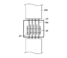
図4を参照して、機械式継手21を有する接合部14にあばら方向せん断補強筋22を配置する意義について説明する。図4は、地震時に接合部8,14に生じる力F及びひずみεを模式的に示す図である。接合部8に機械式継手21がない従来技術では、梁主筋6に曲げモーメントに対応した引張力Ftが加わるが、通し配筋となっている梁主筋6の径と表面の凹凸とが一様であるため、梁主筋6のひずみε分布は、図4(a)に示すように、梁端で最も大きくなるような分布形状となる。接合部8内の梁主筋6とコンクリートとの間には、付着力Faが作用して、梁主筋6の引張力Ftがコンクリートに伝達される。梁主筋6の径及び表面の凹凸に依存する付着抵抗は一様であるため、コンクリートにも一様な力が伝達される。このため、接合部8全体で損傷に抵抗し、接合部8のコンクリートの損傷は分散される傾向にある。
With reference to FIG. 4, the significance of disposing the
一方、機械式継手21がある場合は、機械式継手21の断面積、径及び外周表面積が梁主筋18よりも大きいため、図4(b)に示す状況となる。梁主筋18のひずみεは端部に集中する。機械式継手21部分では、断面積が大きいためにひずみは小さいが、表面積が大きいために付着抵抗力が大きくなり、その結果、コンクリートの狭い範囲に大きな力が作用する。そこで、図4(c)に示すようにあばら方向せん断補強筋22を設けて、その力に抵抗する。また、機械式継手21の小口部分では、コンクリートを押す力(支圧力)Fcが作用するため、接合部18における機械式継手21よりも外側にあばら方向せん断補強筋22を設置することによりコンクリートの損傷を抑制することができる。
On the other hand, when the mechanical joint 21 is present, the cross-sectional area, diameter, and outer peripheral surface area of the mechanical joint 21 are larger than those of the beam
このように、接合部18内に機械式継手21を設けた場合には、通し配筋に比べて、接合部18内のコンクリートに作用する力が機械式継手21の表面近傍及び小口部分に集中するため、接合部18が損傷しやすくなる。そこで、あばら方向せん断補強筋22を設けることにより、あばら方向せん断補強筋22が、機械式継手21の外面近傍では付着力によって発生する付着割裂ひび割れに抵抗し、機械式継手21の小口部近傍では付着割裂ひび割れに抵抗するとともに、支圧力の発生するコンクリート部分を拘束して、接合部18内コンクリートにおける有効な抵抗容積を拡大させる効果を発揮する。なお、支圧が作用する仕口部分では、あばら方向せん断補強筋22を梁主筋18に当接するように配筋してもよく(図4中の左端のあばら方向せん断補強筋22)、わずかに離間した状態で近接するように、例えば機械式継手21に当接させたあばら方向せん断補強筋22とX方向に整合するように配筋してもよい(図4中の右端のあばら方向せん断補強筋22)。
As described above, when the mechanical joint 21 is provided in the
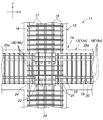
次に、図5〜7を参照して、梁13がプレキャストコンクリートである場合を例に柱梁接合構造11の施工方法について説明する。図6は、各部材を簡略化して示している。
Next, with reference to FIGS. 5-7, the construction method of the column
図6(a)に示すように、まず、柱12を立設する。柱12は、プレキャストコンクリート製であっても現場で打設されたものであってもよい。
As shown in FIG. 6A, first, the
柱12の立設の前若しくは後、又は柱12の立設と同時に、以下の作業が工場又は施工現場の地上において行われる。第1梁13aは接合部14で梁主筋18aが連結される2つのプレキャストコンクリート製の第1梁部材25aからなるところ、機械式継手21を、一方の第1梁部材25aの梁主筋18aの端部に仮組み付けする。図7に示すように、第2梁13bは、接合部14の梁主筋18bが通し配筋となっている第2梁部材25bからなる。第2梁部材25bの重量及び第2梁部材25bを設置するためのクレーンの揚重能力によっては、第2梁部材25bの端部には、第2梁13bの中間部で他の第2梁部材25bに連結される継手が設けられる。さらに、あばら方向せん断補強筋22を組み付けする。あばら方向せん断補強筋22の組み付けは、第2梁部材25bの通し配筋の梁主筋18bに対して行われる。まず、梁主筋18bに対して、これに直交して水平な方向に段取り筋29を設置する。段取り筋29にあばら方向せん断補強筋22を組み付け、第2梁部材25b及び第1梁部材25aを柱12に対して目的の位置に配置したときに、あばら方向せん断補強筋22が第1梁部材25aの梁主筋又は機械式継手21に当接又は近接するようにする。段取り筋29は、あばら方向せん断補強筋22よりも細い鉄筋でよい。なお、あばら方向副せん断補強筋23も、この段階で、段取り筋29に組み付けすることが好ましい(図示せず)。さらに、図示しない針金や段取り筋を用いて、帯方向せん断補強筋24を第2梁部材25bの所定の位置に配置する。
The following operations are performed on the ground of the factory or the construction site before or after the
次に、図6(b)に示すように、第2梁部材25bを柱12に対して目的の位置に配置する。次いで、図6(c)に示すように、2つの第1梁部材25aを柱12に対して目的の位置に配置する。このとき第1梁部材25aと第2梁部材25bとの梁主筋18を交差させるため、第1梁部材25aは、所定の高さまで持ち上げられた後、X方向に移動させる
Next, as shown in FIG. 6B, the
次に、図6(d)に示すように、仮組み付けされていた機械式継手21によって、2つの第1梁部材25aの梁主筋18aを連結する。さらに、組み付けられていたあばら方向せん断補強筋22の位置を調整して第1梁部材25aの梁主筋18a又は機械式継手21に当接又は近接させる。さらに、あばら方向副せん断補強筋23の位置を調整して第1梁部材25aの梁主筋18a又は機械式継手21に当接又は近接させ、帯方向せん断補強筋24の位置を調整する。なお、帯方向せん断補強筋24の一部又は全部は、柱12に取り付ける前の第2梁部材25bに組み付けることに代えて、この段階で柱主筋15に組みつけてもよい。
Next, as shown in FIG. 6D, the beam
最後に、図6(e)に示すように接合部14にコンクリートを打設する。 Finally, as shown in FIG. 6 (e), concrete is placed in the joint 14.
なお、梁部材25の設置前にあばら方向せん断補強筋22及びあばら方向副せん断補強筋23の組み付けを行わず、梁部材25の設置後にあばら方向せん断補強筋22及びあばら方向副せん断補強筋23を組みつけてもよい。また、第2梁13bがない場合には、あばら方向せん断補強筋22及びあばら方向副せん断補強筋23を第1梁部材25aの梁主筋18a又は機械式継手21に組み付け、その後、第1梁部材25aを柱12に対して配置してもよい。第2梁13bを接合部14内で梁主筋18bが継手されるように変形した場合、あばら方向せん断補強筋22の組み付けは、第1梁部材25a及び第2梁部材25bの柱12への配置の前に、第1梁部材25aの梁主筋18a又は機械式継手21に対して行ってもよく、第2梁部材25bに段取り筋29を設けた後に段取り筋29に対して行ってもよい。
In addition, before the beam member 25 is installed, the loose direction
従来技術では、帯方向にのみせん断補強筋を配置していたが、機械式継手21が梁主筋18aよりも太いため、せん断補強筋が上下の機械式継手21の狭いスペースに集中させる必要があり、施工が困難であった。本発明の上記実施形態では、主に第1梁13aのあばら筋19の延在方向と同一の方向にせん断補強筋を設けるため、他の部材との取り合いの調整が容易となる。また、あばら方向せん断補強筋22及びあばら方向副せん断補強筋23は、工場又は施工現場の地上で取り付けることができるため、施工の作業性が向上している。
In the prior art, the shear reinforcement bars are arranged only in the band direction. However, since the
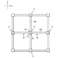
図8は、上記実施形態の変形例を示す平面図である。この変形例は、第2梁13bのあばら筋19及び副あばら筋20と同じ方向に第2あばら方向せん断補強筋27及び第2あばら方向副せん断補強筋28が設けられている点で上記実施形態と異なる。第2あばら方向せん断補強筋27及び第2あばら方向副せん断補強筋28は、上下方向に延在する部分を含むように第2梁13bのあばら筋19によって画定される平面に平行に、X方向に延在する帯筋16の内側かつ梁主筋18の外側に配置され、主に第2梁13bのすべりを抑制する。
FIG. 8 is a plan view showing a modification of the above embodiment. In this modified example, the second rib direction
以上で具体的実施形態の説明を終えるが、本発明は上記実施形態に限定されることなく幅広く変形実施することができる。例えば、第2梁がなくX方向の第1梁のみが延在する柱梁接合部や、第2梁がY方向の片側にのみ延出して平面視で丁字状に梁が交差する柱梁接合部にも本発明を適用できる。接合部には、第2梁のあばら筋が画定する平面に平行な方向にも、あばら方向せん断補強筋及びあばら方向副せん断補強筋の一方又は双方を配置してもよい。柱及び梁の一方又は双方をプレストレストコンクリートとしてもよい。 Although the description of the specific embodiment is finished as described above, the present invention is not limited to the above embodiment and can be widely modified. For example, a column beam joint in which only the first beam in the X direction extends without the second beam, or a column beam junction in which the second beam extends only to one side in the Y direction and the beams intersect in a letter shape in plan view. The present invention can also be applied to the section. One or both of the rib-direction shear reinforcement bar and the rib-direction secondary shear reinforcement bar may be arranged in the joint portion in a direction parallel to the plane defined by the rib bars of the second beam. One or both of the columns and beams may be prestressed concrete.
11:柱梁接合構造
12:柱
13:梁(13a:第1梁、13b:第2梁)
14:接合部
15:柱主筋
18:梁主筋(18a:第1梁の梁主筋、18b:第2梁の梁主筋)
21:機械式継手
22:あばら方向せん断補強筋
25a:第1梁部材
11: beam-to-column connection structure 12: column 13: beam (13a: first beam, 13b: second beam)
14: Joint 15: Column main bar 18: Beam main bar (18a: Beam main bar of the first beam, 18b: Beam main bar of the second beam)
21: mechanical joint 22:
Claims (6)
前記梁主筋は、少なくとも上下2段に配置されており、
前記柱梁接合部を補強するせん断補強筋は、柱において前記所定の方向における最も外側に配置された柱主筋の間に配置され、かつ上下方向に延在する部分を有するあばら方向せん断補強筋を含むことを特徴とする柱梁接合構造。 A beam-to-column connection structure including a mechanical joint in a beam-to-column joint for connecting beam main bars of a beam extending in a predetermined direction,
The beam main bars are arranged in at least two upper and lower stages,
The shear reinforcing bar for reinforcing the beam-column joint is a rib shear reinforcing bar that is disposed between the column main bars arranged on the outermost side in the predetermined direction in the column and has a portion extending in the vertical direction. Column beam connection structure characterized by including.
少なくとも上下2段に配置された梁主筋を含むプレキャストコンクリート製の2つの第1梁部材を、前記柱の両側に直線状となるように、かつ各々の一端側が前記柱との接合部に位置するように配置するステップと、
前記柱の上方に配置された機械式継手によって前記2つの第1梁部材の前記梁主筋を互いに連結するステップと、
前記接合部のせん断補強筋を設置するステップと、
前記接合部に、コンクリートを打設するステップとを備え、
前記せん断補強筋を設置するステップは、上下方向に延在する部分を有して前記梁主筋に直交する平面に平行な方向に延在するべきあばら方向せん断補強筋を前記梁主筋又は前記機械式継手に当接又は近接するべき位置に組み付けるステップを含むことを特徴とする柱梁接合構造の施工方法。 A step of standing a pillar;
Two first beam members made of precast concrete including beam main bars arranged in at least two upper and lower stages are linearly formed on both sides of the column, and one end side of each is positioned at a joint portion with the column. Step to arrange and
Connecting the beam main bars of the two first beam members to each other by a mechanical joint disposed above the column;
Installing a shear reinforcement for the joint;
Placing concrete in the joint, and
The step of installing the shear reinforcing bar includes a beam-direction shear reinforcing bar or a mechanical type which has a portion extending in the vertical direction and is to be extended in a direction parallel to a plane perpendicular to the beam main bar. A method for constructing a beam-to-column connection structure, comprising a step of assembling at a position where the joint should abut or be close to the joint.
前記接合部における前記第2梁部材の梁主筋は通し配筋であり、
前記あばら方向せん断補強筋を組み付けるステップは、前記第2梁部材を配置するステップよりも前に、前記第2梁部材に対して行われることを特徴とする請求項5に記載の柱梁接合構造の施工方法。 A step of placing a second beam member arranged in a direction intersecting the first beam member with respect to the column; and the step of arranging the second beam member comprises the step of arranging the first beam member. Done before,
The beam main bar of the second beam member at the joint is a through bar,
6. The beam-column joining structure according to claim 5, wherein the step of assembling the loose shear reinforcement is performed on the second beam member prior to the step of arranging the second beam member. Construction method.
Priority Applications (1)
| Application Number | Priority Date | Filing Date | Title |
|---|---|---|---|
| JP2016071794A JP6645894B2 (en) | 2016-03-31 | 2016-03-31 | Construction method of beam-column joint structure |
Applications Claiming Priority (1)
| Application Number | Priority Date | Filing Date | Title |
|---|---|---|---|
| JP2016071794A JP6645894B2 (en) | 2016-03-31 | 2016-03-31 | Construction method of beam-column joint structure |
Publications (2)
| Publication Number | Publication Date |
|---|---|
| JP2017179997A true JP2017179997A (en) | 2017-10-05 |
| JP6645894B2 JP6645894B2 (en) | 2020-02-14 |
Family
ID=60005206
Family Applications (1)
| Application Number | Title | Priority Date | Filing Date |
|---|---|---|---|
| JP2016071794A Active JP6645894B2 (en) | 2016-03-31 | 2016-03-31 | Construction method of beam-column joint structure |
Country Status (1)
| Country | Link |
|---|---|
| JP (1) | JP6645894B2 (en) |
Cited By (5)
| Publication number | Priority date | Publication date | Assignee | Title |
|---|---|---|---|---|
| CN108179808A (en) * | 2018-01-25 | 2018-06-19 | 中国建筑股份有限公司 | A kind of prefabricated beam column crimping joint strengthening stirrup construction and its construction method |
| CN109356287A (en) * | 2018-11-08 | 2019-02-19 | 大连万达集团股份有限公司 | The cylindrical cap node and manufacturing process of one Zhu Duo beam intersection of concrete |
| CN110005075A (en) * | 2019-04-03 | 2019-07-12 | 江苏中原建设集团有限公司 | A kind of construction method of strengthening concrete bean column node |
| JP2020097844A (en) * | 2018-12-18 | 2020-06-25 | 株式会社竹中工務店 | Column-beam joint structure |
| JP2021055472A (en) * | 2019-10-01 | 2021-04-08 | 五洋建設株式会社 | Construction method of column-beam joint structure and column-beam joint structure |
Citations (3)
| Publication number | Priority date | Publication date | Assignee | Title |
|---|---|---|---|---|
| JP2000144894A (en) * | 1998-11-17 | 2000-05-26 | Mitsui Constr Co Ltd | Method for joint between precast concrete column and beam |
| JP2000336747A (en) * | 1999-05-31 | 2000-12-05 | Kajima Corp | Execution method of beam-column connection |
| KR20060098555A (en) * | 2005-03-03 | 2006-09-19 | 한밭대학교 산학협력단 | Connection system with headed reinforcements for precast concrete beam-column joint |
-
2016
- 2016-03-31 JP JP2016071794A patent/JP6645894B2/en active Active
Patent Citations (3)
| Publication number | Priority date | Publication date | Assignee | Title |
|---|---|---|---|---|
| JP2000144894A (en) * | 1998-11-17 | 2000-05-26 | Mitsui Constr Co Ltd | Method for joint between precast concrete column and beam |
| JP2000336747A (en) * | 1999-05-31 | 2000-12-05 | Kajima Corp | Execution method of beam-column connection |
| KR20060098555A (en) * | 2005-03-03 | 2006-09-19 | 한밭대학교 산학협력단 | Connection system with headed reinforcements for precast concrete beam-column joint |
Cited By (7)
| Publication number | Priority date | Publication date | Assignee | Title |
|---|---|---|---|---|
| CN108179808A (en) * | 2018-01-25 | 2018-06-19 | 中国建筑股份有限公司 | A kind of prefabricated beam column crimping joint strengthening stirrup construction and its construction method |
| CN109356287A (en) * | 2018-11-08 | 2019-02-19 | 大连万达集团股份有限公司 | The cylindrical cap node and manufacturing process of one Zhu Duo beam intersection of concrete |
| JP2020097844A (en) * | 2018-12-18 | 2020-06-25 | 株式会社竹中工務店 | Column-beam joint structure |
| JP7087260B2 (en) | 2018-12-18 | 2022-06-21 | 株式会社竹中工務店 | Column-beam joint structure |
| CN110005075A (en) * | 2019-04-03 | 2019-07-12 | 江苏中原建设集团有限公司 | A kind of construction method of strengthening concrete bean column node |
| JP2021055472A (en) * | 2019-10-01 | 2021-04-08 | 五洋建設株式会社 | Construction method of column-beam joint structure and column-beam joint structure |
| JP7330048B2 (en) | 2019-10-01 | 2023-08-21 | 五洋建設株式会社 | Column-beam connection structure construction method and column-beam connection structure |
Also Published As
| Publication number | Publication date |
|---|---|
| JP6645894B2 (en) | 2020-02-14 |
Similar Documents
| Publication | Publication Date | Title |
|---|---|---|
| JP4823790B2 (en) | Column unit and method of building building using column unit | |
| JP2017179997A (en) | Column-beam joint structure and construction method therefor | |
| KR101030419B1 (en) | Joint structure of vertical member and horizontal member | |
| KR101295740B1 (en) | Joint of Steel Column | |
| KR101937680B1 (en) | Prefabricated Precast Structure and Construction Method Thereof | |
| KR101809687B1 (en) | Joining Members of Steel Concrete Column and Steel Beam and Construction Method Thereof | |
| KR101228012B1 (en) | Precast concrete column connecting structure | |
| KR20170027236A (en) | the rigid connection structure between precast concrete column and precast concrete girder and the rigid connection structure between precast concrete girder and precast concrete beam using the plate, the modular system using the same | |
| JP4943141B2 (en) | Joint structure of reinforced concrete columns and steel beams | |
| KR101750177B1 (en) | Punching shear stiffening member of cutting bridge type and method for constructing footing using of the same | |
| JP2008266910A (en) | Projection structure of anchorage or deviator of tendon, and construction method therefor | |
| JP5602455B2 (en) | Beam members and building structures | |
| KR101521946B1 (en) | Enlarged capital of steel framed reinforced concrete column | |
| KR20130096969A (en) | Steel composite beam for reducing story height, slim floor structure and construction method using the same | |
| JP7391172B2 (en) | Joint structure between concrete-filled steel pipe column and reinforced concrete slab | |
| JP7158231B2 (en) | Composite column, bridge pier using same, construction method | |
| JP6428027B2 (en) | Column rebar connection panel and rebar structure | |
| KR100710583B1 (en) | Hybrid system of pc column and steel beam | |
| JP6855296B2 (en) | Building foundation structure and its construction method | |
| JP2016205051A (en) | Construction method for structure | |
| JP7010709B2 (en) | How to build prefabricated and concrete structures | |
| KR20120008667A (en) | Beam construction method using deckplate end-reinforcing member | |
| JP5344702B2 (en) | Column and slab joint structure | |
| JP4439938B2 (en) | Wall type reinforced concrete structure and its construction method | |
| KR101625593B1 (en) | Concrete filled tube column structure |
Legal Events
| Date | Code | Title | Description |
|---|---|---|---|
| A621 | Written request for application examination |
Free format text: JAPANESE INTERMEDIATE CODE: A621 Effective date: 20180921 |
|
| A131 | Notification of reasons for refusal |
Free format text: JAPANESE INTERMEDIATE CODE: A131 Effective date: 20190730 |
|
| A977 | Report on retrieval |
Free format text: JAPANESE INTERMEDIATE CODE: A971007 Effective date: 20190731 |
|
| A521 | Request for written amendment filed |
Free format text: JAPANESE INTERMEDIATE CODE: A523 Effective date: 20190823 |
|
| TRDD | Decision of grant or rejection written | ||
| A01 | Written decision to grant a patent or to grant a registration (utility model) |
Free format text: JAPANESE INTERMEDIATE CODE: A01 Effective date: 20200107 |
|
| A61 | First payment of annual fees (during grant procedure) |
Free format text: JAPANESE INTERMEDIATE CODE: A61 Effective date: 20200109 |
|
| R150 | Certificate of patent or registration of utility model |
Ref document number: 6645894 Country of ref document: JP Free format text: JAPANESE INTERMEDIATE CODE: R150 |
|
| R250 | Receipt of annual fees |
Free format text: JAPANESE INTERMEDIATE CODE: R250 |