JP2017169252A - 支持部材 - Google Patents
支持部材 Download PDFInfo
- Publication number
- JP2017169252A JP2017169252A JP2016049199A JP2016049199A JP2017169252A JP 2017169252 A JP2017169252 A JP 2017169252A JP 2016049199 A JP2016049199 A JP 2016049199A JP 2016049199 A JP2016049199 A JP 2016049199A JP 2017169252 A JP2017169252 A JP 2017169252A
- Authority
- JP
- Japan
- Prior art keywords
- plate
- press
- protrusion
- receiving portion
- support member
- Prior art date
- Legal status (The legal status is an assumption and is not a legal conclusion. Google has not performed a legal analysis and makes no representation as to the accuracy of the status listed.)
- Granted
Links
- 239000002184 metal Substances 0.000 claims abstract description 11
- 229920005989 resin Polymers 0.000 claims abstract description 7
- 239000011347 resin Substances 0.000 claims abstract description 7
- 238000004519 manufacturing process Methods 0.000 abstract description 5
- 238000007789 sealing Methods 0.000 description 7
- 230000002093 peripheral effect Effects 0.000 description 6
- 239000012530 fluid Substances 0.000 description 5
- 230000005540 biological transmission Effects 0.000 description 3
- 238000000034 method Methods 0.000 description 3
- 238000000465 moulding Methods 0.000 description 3
- 238000005452 bending Methods 0.000 description 2
- 238000010586 diagram Methods 0.000 description 2
- 238000000605 extraction Methods 0.000 description 2
- 239000010720 hydraulic oil Substances 0.000 description 2
- 238000003780 insertion Methods 0.000 description 2
- 230000037431 insertion Effects 0.000 description 2
- 238000003825 pressing Methods 0.000 description 2
- 238000005520 cutting process Methods 0.000 description 1
- 230000007423 decrease Effects 0.000 description 1
- 238000000926 separation method Methods 0.000 description 1
- 229920003002 synthetic resin Polymers 0.000 description 1
- 239000000057 synthetic resin Substances 0.000 description 1
- 239000013585 weight reducing agent Substances 0.000 description 1
Images


Classifications
-
- F—MECHANICAL ENGINEERING; LIGHTING; HEATING; WEAPONS; BLASTING
- F16—ENGINEERING ELEMENTS AND UNITS; GENERAL MEASURES FOR PRODUCING AND MAINTAINING EFFECTIVE FUNCTIONING OF MACHINES OR INSTALLATIONS; THERMAL INSULATION IN GENERAL
- F16B—DEVICES FOR FASTENING OR SECURING CONSTRUCTIONAL ELEMENTS OR MACHINE PARTS TOGETHER, e.g. NAILS, BOLTS, CIRCLIPS, CLAMPS, CLIPS OR WEDGES; JOINTS OR JOINTING
- F16B4/00—Shrinkage connections, e.g. assembled with the parts at different temperature; Force fits; Non-releasable friction-grip fastenings
- F16B4/004—Press fits, force fits, interference fits, i.e. fits without heat or chemical treatment
-
- F—MECHANICAL ENGINEERING; LIGHTING; HEATING; WEAPONS; BLASTING
- F16—ENGINEERING ELEMENTS AND UNITS; GENERAL MEASURES FOR PRODUCING AND MAINTAINING EFFECTIVE FUNCTIONING OF MACHINES OR INSTALLATIONS; THERMAL INSULATION IN GENERAL
- F16B—DEVICES FOR FASTENING OR SECURING CONSTRUCTIONAL ELEMENTS OR MACHINE PARTS TOGETHER, e.g. NAILS, BOLTS, CIRCLIPS, CLAMPS, CLIPS OR WEDGES; JOINTS OR JOINTING
- F16B5/00—Joining sheets or plates, e.g. panels, to one another or to strips or bars parallel to them
- F16B5/0004—Joining sheets, plates or panels in abutting relationship
- F16B5/0008—Joining sheets, plates or panels in abutting relationship by moving the sheets, plates or panels substantially in their own plane, perpendicular to the abutting edge
- F16B5/0024—Joining sheets, plates or panels in abutting relationship by moving the sheets, plates or panels substantially in their own plane, perpendicular to the abutting edge the sheets, plates or panels having holes, e.g. for dowel- type connections
-
- F—MECHANICAL ENGINEERING; LIGHTING; HEATING; WEAPONS; BLASTING
- F16—ENGINEERING ELEMENTS AND UNITS; GENERAL MEASURES FOR PRODUCING AND MAINTAINING EFFECTIVE FUNCTIONING OF MACHINES OR INSTALLATIONS; THERMAL INSULATION IN GENERAL
- F16B—DEVICES FOR FASTENING OR SECURING CONSTRUCTIONAL ELEMENTS OR MACHINE PARTS TOGETHER, e.g. NAILS, BOLTS, CIRCLIPS, CLAMPS, CLIPS OR WEDGES; JOINTS OR JOINTING
- F16B5/00—Joining sheets or plates, e.g. panels, to one another or to strips or bars parallel to them
- F16B5/0004—Joining sheets, plates or panels in abutting relationship
- F16B5/0084—Joining sheets, plates or panels in abutting relationship characterised by particular locking means
-
- H—ELECTRICITY
- H02—GENERATION; CONVERSION OR DISTRIBUTION OF ELECTRIC POWER
- H02G—INSTALLATION OF ELECTRIC CABLES OR LINES, OR OF COMBINED OPTICAL AND ELECTRIC CABLES OR LINES
- H02G3/00—Installations of electric cables or lines or protective tubing therefor in or on buildings, equivalent structures or vehicles
- H02G3/30—Installations of cables or lines on walls, floors or ceilings
-
- F—MECHANICAL ENGINEERING; LIGHTING; HEATING; WEAPONS; BLASTING
- F16—ENGINEERING ELEMENTS AND UNITS; GENERAL MEASURES FOR PRODUCING AND MAINTAINING EFFECTIVE FUNCTIONING OF MACHINES OR INSTALLATIONS; THERMAL INSULATION IN GENERAL
- F16B—DEVICES FOR FASTENING OR SECURING CONSTRUCTIONAL ELEMENTS OR MACHINE PARTS TOGETHER, e.g. NAILS, BOLTS, CIRCLIPS, CLAMPS, CLIPS OR WEDGES; JOINTS OR JOINTING
- F16B5/00—Joining sheets or plates, e.g. panels, to one another or to strips or bars parallel to them
- F16B5/02—Joining sheets or plates, e.g. panels, to one another or to strips or bars parallel to them by means of fastening members using screw-thread
Abstract
Description
前記プレートは、側端部に突起を有し、前記受け部は前記支持面の面方向と交差する方向に沿った壁面を有し、前記プレートの側端部が前記壁面に沿って配置され、前記壁面に前記突起が食い込んで係止される構成であるとよい。これによれば、本体部の支持面の面方向と交差する方向からプレートを受け部に圧入することができ、プレートの圧入作業を円滑に行うことができる。
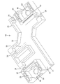
本発明の実施例1を図1〜図6によって説明する。実施例1の支持部材10は、自動車の自動変速機の油圧制御装置90に搭載されるものであって、合成樹脂製の本体部20と、本体部20に固定される金属製のプレート60とを備えている。なお、以下の説明において、上下方向は、自動車に搭載された状態を基準とする。
まず、プレート60が、本体部20の上方から受け部25に向けて降ろされ、受け部25の圧入空間30に圧入される。プレート60の圧入過程では、圧入部62の基部67が背壁28の壁面部分に沿ってスライドされるとともに、各突起71、72、73が両側壁27の壁面29に食い込むように進入する。この際、第1突起71、第2突起72、第3突起73の順に壁面29への食い込みが開始される。
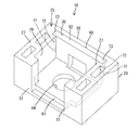
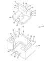
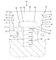
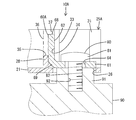
図7〜図10は、本発明の実施例2を示す。実施例2の支持部材10Aは、受け部25Aの形態が実施例1とは異なる。もっとも、受け部25Aの基本構造は、実施例1の受け部25Aと同様である。このため、以下においては、実施例1の受け部25Aに追加された部分を中心に説明し、実施例1と同一又は相当する部分については同一符号を付す。
本発明の他の実施例を簡単に説明する。
(1)本体部の支持面には、導電部材として、電線以外に、例えば、バスバーが支持されるものであってもよい。
(2)開口部は、受け部の底壁の外周縁に開放されていてもよい。
(3)本体部は、ブロック状の形態であってもよい。
(4)ボルトの頭部とプレートとの間に座金が介在していてもよい。また、固定部の座面には、ナットが載置される構成であってもよい。
(5)弾性ロック部は、受け部に2つ以上設けられていてもよい。
(6)受け部は、背壁と対向する位置に前壁を有し、四方を包囲する形態になっていてもよい。
(7)本発明は、油圧制御装置に限らず、導電部材を支持する支持部材が取り付けられる装置に広く適用可能である。
20、20A…本体部
23…支持面
25、25A…受け部
26…開口部
29…壁面
34…封入部
36…弾性ロック部
60、60A…プレート
61…固定部
62…圧入部
64…通し孔
71…第1突起(突起)
72…第2突起(突起)
73…第3突起(突起)
80…ボルト
90…油圧制御装置(装置)
Claims (6)
- 導電部材を支持する支持面を有する樹脂製の本体部と、ボルトの通し孔を有して装置に取り付けられる金属製のプレートとを備え、
前記本体部は、前記プレートを圧入して固定する受け部を有していることを特徴とする支持部材。 - 前記プレートは、側端部に突起を有し、
前記受け部は前記支持面の面方向と交差する方向に沿った壁面を有し、前記プレートの側端部が前記壁面に沿って配置され、前記壁面に前記突起が食い込んで係止される構成である請求項1記載の支持部材。 - 前記プレートは、前記突起を有する圧入部と、前記圧入部に屈曲して連なり前記通し孔を有する固定部とを有し、
前記受け部は、前記通し孔と連通し、前記固定部を前記装置に臨ませる開口部を有している請求項2記載の支持部材。 - 前記プレートは、側端部に前記受け部への圧入方向に並ぶ複数の突起を有し、前記受け部は、前記突起が食い込んで係止される壁面を有しており、前記複数の突起は、圧入方向前方のものから圧入方向後方のものにかけて段々大きく突出するように構成されている請求項1ないし3のいずれか1項記載の支持部材。
- 前記プレートは、側端部に突起を有し、
前記受け部は、前記突起が食い込んで係止される壁面を有し、かつ前記壁面を奥側に配置して前記プレートの側端部を覆う封入部を有している請求項1ないし4のいずれか1項記載の支持部材。 - 前記本体部は、前記プレートに対し前記受け部からの抜け出しを規制する弾性をもった弾性ロック部を有している請求項1ないし5のいずれか1項記載の支持部材。
Priority Applications (4)
| Application Number | Priority Date | Filing Date | Title |
|---|---|---|---|
| JP2016049199A JP6455732B2 (ja) | 2016-03-14 | 2016-03-14 | 支持部材 |
| US16/084,443 US10844889B2 (en) | 2016-03-14 | 2017-02-21 | Support member |
| PCT/JP2017/006320 WO2017159232A1 (ja) | 2016-03-14 | 2017-02-21 | 支持部材 |
| CN201780015241.5A CN108780987B (zh) | 2016-03-14 | 2017-02-21 | 支承部件 |
Applications Claiming Priority (1)
| Application Number | Priority Date | Filing Date | Title |
|---|---|---|---|
| JP2016049199A JP6455732B2 (ja) | 2016-03-14 | 2016-03-14 | 支持部材 |
Publications (3)
| Publication Number | Publication Date |
|---|---|
| JP2017169252A true JP2017169252A (ja) | 2017-09-21 |
| JP2017169252A5 JP2017169252A5 (ja) | 2018-07-05 |
| JP6455732B2 JP6455732B2 (ja) | 2019-01-23 |
Family
ID=59850691
Family Applications (1)
| Application Number | Title | Priority Date | Filing Date |
|---|---|---|---|
| JP2016049199A Active JP6455732B2 (ja) | 2016-03-14 | 2016-03-14 | 支持部材 |
Country Status (4)
| Country | Link |
|---|---|
| US (1) | US10844889B2 (ja) |
| JP (1) | JP6455732B2 (ja) |
| CN (1) | CN108780987B (ja) |
| WO (1) | WO2017159232A1 (ja) |
Families Citing this family (1)
| Publication number | Priority date | Publication date | Assignee | Title |
|---|---|---|---|---|
| JP6287888B2 (ja) * | 2015-02-18 | 2018-03-07 | 株式会社オートネットワーク技術研究所 | ケース |
Citations (3)
| Publication number | Priority date | Publication date | Assignee | Title |
|---|---|---|---|---|
| JPS6214919U (ja) * | 1985-07-11 | 1987-01-29 | ||
| JP2003102116A (ja) * | 2001-09-21 | 2003-04-04 | Yazaki Corp | プロテクタ |
| JP2014220866A (ja) * | 2013-05-01 | 2014-11-20 | 矢崎総業株式会社 | ワイヤーハーネスの車体仮固定構造 |
Family Cites Families (9)
| Publication number | Priority date | Publication date | Assignee | Title |
|---|---|---|---|---|
| JPS6214919A (ja) | 1985-07-15 | 1987-01-23 | ユ−オ−ピ−・インコ−ポレ−テツド | 煙道ガス硫黄酸化物の除去 |
| CN100403609C (zh) * | 2002-07-26 | 2008-07-16 | 松下电工株式会社 | 布线器具 |
| JP4341513B2 (ja) * | 2004-09-10 | 2009-10-07 | 住友電装株式会社 | ハーネスプロテクタ |
| JP2007106060A (ja) * | 2005-10-17 | 2007-04-26 | Funai Electric Co Ltd | プリンタ装置 |
| DE102010043509A1 (de) * | 2010-11-05 | 2012-05-10 | Hilti Aktiengesellschaft | Erdungskontakt |
| CN203651627U (zh) * | 2011-02-22 | 2014-06-18 | 爱信精机株式会社 | 台阶单元 |
| JP5606511B2 (ja) * | 2011-11-25 | 2014-10-15 | 浙江三花股▲分▼有限公司 | 電動切換弁 |
| JP6297904B2 (ja) * | 2014-04-21 | 2018-03-20 | 矢崎総業株式会社 | 被支持部材と支持体との係止構造 |
| JP6597375B2 (ja) * | 2016-02-19 | 2019-10-30 | 株式会社オートネットワーク技術研究所 | 配線構造 |
-
2016
- 2016-03-14 JP JP2016049199A patent/JP6455732B2/ja active Active
-
2017
- 2017-02-21 CN CN201780015241.5A patent/CN108780987B/zh active Active
- 2017-02-21 US US16/084,443 patent/US10844889B2/en active Active
- 2017-02-21 WO PCT/JP2017/006320 patent/WO2017159232A1/ja active Application Filing
Patent Citations (3)
| Publication number | Priority date | Publication date | Assignee | Title |
|---|---|---|---|---|
| JPS6214919U (ja) * | 1985-07-11 | 1987-01-29 | ||
| JP2003102116A (ja) * | 2001-09-21 | 2003-04-04 | Yazaki Corp | プロテクタ |
| JP2014220866A (ja) * | 2013-05-01 | 2014-11-20 | 矢崎総業株式会社 | ワイヤーハーネスの車体仮固定構造 |
Also Published As
| Publication number | Publication date |
|---|---|
| US10844889B2 (en) | 2020-11-24 |
| CN108780987A (zh) | 2018-11-09 |
| CN108780987B (zh) | 2020-04-21 |
| JP6455732B2 (ja) | 2019-01-23 |
| US20190078597A1 (en) | 2019-03-14 |
| WO2017159232A1 (ja) | 2017-09-21 |
Similar Documents
| Publication | Publication Date | Title |
|---|---|---|
| JP4765818B2 (ja) | 電線カバー | |
| DE102015114250A1 (de) | Steckverbinderanordnung | |
| JP6056706B2 (ja) | コネクタ | |
| US10820432B2 (en) | Board unit with a tool-insertion recessed portion to release engagement between the case and the cover | |
| JP6488978B2 (ja) | 防水コネクタ | |
| JP2015095358A (ja) | 機器用コネクタ | |
| JP6455732B2 (ja) | 支持部材 | |
| JP2014170725A (ja) | 電子部品付きコネクタおよびホルダ | |
| US8821187B2 (en) | Board connector | |
| JP6597804B2 (ja) | 蓄電モジュール | |
| US20160133889A1 (en) | Battery holder | |
| JP2005317363A (ja) | コネクタ | |
| JP2015095356A (ja) | コネクタ | |
| JP6065765B2 (ja) | 電子部品付きコネクタ | |
| WO2017077831A1 (ja) | コネクタ | |
| JP2015095354A (ja) | 機器用コネクタ及びその製造方法 | |
| JP2015207448A (ja) | コネクタ | |
| JP2006040818A (ja) | コネクタ | |
| JP2013143286A (ja) | 基板用コネクタ | |
| JP5999509B2 (ja) | カードエッジコネクタ | |
| JP2018010797A (ja) | 端子台 | |
| JP2016062685A (ja) | コネクタ | |
| JP6211150B1 (ja) | コネクタ | |
| JP6217573B2 (ja) | コネクタ | |
| JP2018010723A (ja) | 端子台 |
Legal Events
| Date | Code | Title | Description |
|---|---|---|---|
| A521 | Request for written amendment filed |
Free format text: JAPANESE INTERMEDIATE CODE: A523 Effective date: 20180528 |
|
| A621 | Written request for application examination |
Free format text: JAPANESE INTERMEDIATE CODE: A621 Effective date: 20180628 |
|
| TRDD | Decision of grant or rejection written | ||
| A01 | Written decision to grant a patent or to grant a registration (utility model) |
Free format text: JAPANESE INTERMEDIATE CODE: A01 Effective date: 20181122 |
|
| A61 | First payment of annual fees (during grant procedure) |
Free format text: JAPANESE INTERMEDIATE CODE: A61 Effective date: 20181205 |
|
| R150 | Certificate of patent or registration of utility model |
Ref document number: 6455732 Country of ref document: JP Free format text: JAPANESE INTERMEDIATE CODE: R150 |