JP2017160841A - Ride type vehicle - Google Patents
Ride type vehicle Download PDFInfo
- Publication number
- JP2017160841A JP2017160841A JP2016045933A JP2016045933A JP2017160841A JP 2017160841 A JP2017160841 A JP 2017160841A JP 2016045933 A JP2016045933 A JP 2016045933A JP 2016045933 A JP2016045933 A JP 2016045933A JP 2017160841 A JP2017160841 A JP 2017160841A
- Authority
- JP
- Japan
- Prior art keywords
- exhaust
- supercharger
- exhaust passage
- pipe
- type vehicle
- Prior art date
- Legal status (The legal status is an assumption and is not a legal conclusion. Google has not performed a legal analysis and makes no representation as to the accuracy of the status listed.)
- Granted
Links
Images


Classifications
-
- Y—GENERAL TAGGING OF NEW TECHNOLOGICAL DEVELOPMENTS; GENERAL TAGGING OF CROSS-SECTIONAL TECHNOLOGIES SPANNING OVER SEVERAL SECTIONS OF THE IPC; TECHNICAL SUBJECTS COVERED BY FORMER USPC CROSS-REFERENCE ART COLLECTIONS [XRACs] AND DIGESTS
- Y02—TECHNOLOGIES OR APPLICATIONS FOR MITIGATION OR ADAPTATION AGAINST CLIMATE CHANGE
- Y02T—CLIMATE CHANGE MITIGATION TECHNOLOGIES RELATED TO TRANSPORTATION
- Y02T10/00—Road transport of goods or passengers
- Y02T10/10—Internal combustion engine [ICE] based vehicles
- Y02T10/12—Improving ICE efficiencies
Abstract
Description
本発明は、V型エンジンおよび過給機を備えた鞍乗型車両に関する。 The present invention relates to a straddle-type vehicle including a V-type engine and a supercharger.
自動二輪車等の鞍乗型車両に過給機を設け、過給機により圧縮した空気をエンジンの燃焼室へ供給することにより、エンジンの熱効率を高め、出力を増加させることができる。下記の特許文献1ないし3には、前、後にそれぞれ配置された少なくとも一対のシリンダを有する横置きのV型エンジンを搭載した鞍乗型車両において、過給機が設けられたものが記載されている。
By providing a supercharger in a straddle-type vehicle such as a motorcycle and supplying air compressed by the supercharger to the combustion chamber of the engine, the thermal efficiency of the engine can be increased and the output can be increased.
過給機は、一般に、エンジンの燃焼室へ供給する空気を圧縮するコンプレッサ部と、このコンプレッサ部を駆動するタービン部とを備えている。タービン部はタービンホイールを備えており、エンジンの各シリンダから排出される排気の熱エネルギーを利用してタービンホイールを回転させる。そして、タービンホイールの回転によりコンプレッサ部が駆動される。 The supercharger generally includes a compressor unit that compresses air supplied to the combustion chamber of the engine and a turbine unit that drives the compressor unit. The turbine section includes a turbine wheel, and rotates the turbine wheel using the thermal energy of the exhaust discharged from each cylinder of the engine. The compressor unit is driven by the rotation of the turbine wheel.
排気を各シリンダからタービン部へ供給するために、各シリンダの排気ポートとタービン部の吸入口との間には両者を接続する排気管が設けられている。また、タービン部に供給された排気をタービン部からマフラ側へ排出するために、タービン部の排出口とマフラ側との間には送出配管が設けられている。 In order to supply exhaust gas from each cylinder to the turbine section, an exhaust pipe is provided between the exhaust port of each cylinder and the suction port of the turbine section. Further, in order to exhaust the exhaust gas supplied to the turbine part from the turbine part to the muffler side, a delivery pipe is provided between the exhaust port of the turbine part and the muffler side.
ところで、V型エンジンの場合、少なくとも一対のシリンダがエンジンの前、後にそれぞれ配置されているため、並列2気筒または並列4気筒のエンジンと比較して、各シリンダと過給機のタービン部とを接続する排気管が長くなることが多い。例えば、特許文献1の第3図、または特許文献2の第2図には、V型エンジンの各シリンダと過給機のタービン部との間を接続する長い排気管を備えた鞍乗型車両が記載されている。
By the way, in the case of a V-type engine, since at least a pair of cylinders are respectively arranged before and after the engine, each cylinder and the turbocharger turbine section are compared with those of a parallel 2-cylinder or parallel 4-cylinder engine. The exhaust pipe to be connected is often long. For example, in FIG. 3 of
排気管が長いと、排気が各シリンダからタービン部へ供給される間に、排気の熱エネルギーが低下する程度が大きくなり、排気の熱エネルギーによりタービンホイールを回転させる構成においてエネルギー効率が悪くなる。 If the exhaust pipe is long, the degree to which the thermal energy of the exhaust is lowered while the exhaust is supplied from each cylinder to the turbine section becomes large, and the energy efficiency is deteriorated in the configuration in which the turbine wheel is rotated by the thermal energy of the exhaust.
また、鞍乗型車両におけるV型エンジンと過給機との位置関係によっては、前側に配置されたシリンダと過給機のタービン部とを接続する排気管の長さと、後ろ側に配置されたシリンダと過給機のタービン部とを接続する排気管の長さとが大きく異なる場合がある。前側のシリンダと後ろ側のシリンダとで排気管の長さが大きく異なると、前側のシリンダと後ろ側のシリンダとで排気温度の差が大きくなる。このため、前側シリンダと後ろ側シリンダとの間で、燃調または点火時期の設定を大きく異ならせる必要が生じ、その結果、エンジンの出力が低下する場合がある。 Further, depending on the positional relationship between the V-type engine and the supercharger in the saddle-ride type vehicle, the length of the exhaust pipe connecting the cylinder arranged on the front side and the turbine portion of the supercharger is arranged on the rear side. The length of the exhaust pipe that connects the cylinder and the turbine section of the turbocharger may differ greatly. If the length of the exhaust pipe differs greatly between the front cylinder and the rear cylinder, the difference in exhaust temperature between the front cylinder and the rear cylinder increases. For this reason, it is necessary to make the fuel adjustment or ignition timing settings different greatly between the front cylinder and the rear cylinder, and as a result, the engine output may decrease.
本発明は例えば上述したような問題に鑑みなされたものであり、本発明の課題は、V型エンジンに過給機を設けた場合でも、過給機の駆動に関するエネルギー効率を高めることができる鞍乗型車両を提供することにある。また、本発明の他の課題は、V型エンジンと過給機との位置関係によってエンジン出力が低下することを抑制することができる鞍乗型車両を提供することにある。 The present invention has been made in view of, for example, the problems described above, and an object of the present invention is to improve the energy efficiency related to the driving of the supercharger even when the supercharger is provided in the V-type engine. It is to provide a riding type vehicle. Another object of the present invention is to provide a straddle-type vehicle capable of suppressing a decrease in engine output due to a positional relationship between a V-type engine and a supercharger.
上記課題を解決するために、本発明の鞍乗型車両は、前、後にそれぞれ配置された前側シリンダおよび後ろ側シリンダを含む少なくとも一対のシリンダを有するV型エンジンと、前記前側シリンダおよび前記後ろ側シリンダからの排気を用いて駆動し、燃料燃焼用の空気を圧縮する過給機と、前記前側シリンダと前記過給機とを接続し、前記前側シリンダからの排気を前記過給機に供給する第1の排気通路と、前記後ろ側シリンダと前記過給機とを接続し、前記後ろ側シリンダからの排気を前記過給機に供給する第2の排気通路と、前記過給機に接続され、前記過給機から排出された排気を前記V型エンジンの後方へ送出する第3の排気通路とを備え、前記過給機は前記前側シリンダの左右方向一側に配置され、前記第2の排気通路は前記後ろ側シリンダから前記過給機に向かって前記V型エンジンの左右方向一側を通って伸長し、前記第3の排気通路は前記V型エンジンの左右方向一側において前記過給機から前記V型エンジンの後方へ向かって前記第2の排気通路に沿って伸長していることを特徴とする。 In order to solve the above-described problems, a saddle-ride type vehicle according to the present invention includes a V-type engine having at least a pair of cylinders including a front cylinder and a rear cylinder disposed in front and rear, and the front cylinder and the rear side. A turbocharger that is driven using the exhaust from the cylinder and compresses the air for fuel combustion, the front cylinder and the supercharger are connected, and the exhaust from the front cylinder is supplied to the turbocharger. A first exhaust passage, a second exhaust passage for connecting the rear cylinder and the supercharger, and supplying exhaust from the rear cylinder to the supercharger; and the supercharger. A third exhaust passage for sending the exhaust discharged from the supercharger to the rear of the V-type engine, and the supercharger is disposed on one side in the left-right direction of the front cylinder, Exhaust passage is after The third exhaust passage extends from the supercharger to the V-type on one side in the left-right direction of the V-type engine. It extends along the second exhaust passage toward the rear of the engine.
本発明のこの態様においては、過給機が前側シリンダの左右方向一側に配置されており、過給機が前側シリンダの近くに位置している。したがって、前側シリンダと過給機とを接続する第1の排気通路を短くすることができる。これにより、前側シリンダから過給機へ供給される排気の熱エネルギーの低下を抑制することができる。一方、過給機が前側シリンダの左右方向一側に配置されているので、後ろ側シリンダと過給機との間の距離が、前側シリンダと過給機との間の距離と比較して長い。この結果、後ろ側シリンダと過給機とを接続する第2の排気通路が第1の排気通路よりも長くなる。しかしながら、本発明の上記態様によれば、第3の排気通路が、第2の排気通路に沿うように配置されているので、第2の排気通路を通って後ろ側シリンダから過給機へ供給される排気の熱エネルギーの低下を抑制することができる。すなわち、第3の排気通路は、前側シリンダおよび後ろ側シリンダから過給機へ供給された排気を、V型エンジンの後方に設けられた例えばマフラ等へ送り出すための通路であり、第3の排気通路には高温の排気が流通する。第3の排気通路を第2の排気通路に沿うように配置し、第2の排気通路と第3の排気通路とを広い範囲において互いに隣接させることにより、第3の排気通路を流通する排気の熱を利用して、第2の排気通路を流通する排気の温度低下を抑えることができ、当該排気の熱エネルギーの低下を抑制することができる。このように、前側シリンダおよび後ろ側シリンダのそれぞれから過給機へ供給される排気の熱エネルギーの低下を抑制することができるので、過給機の駆動に関するエネルギー効率を良くすることができる。また、前側シリンダの排気温度と後ろ側シリンダの排気温度との差を小さくすることができるので、前側シリンダと後ろ側シリンダとの間で、燃調または点火時期の設定を互いに近づけることができ、エンジン出力の低下を抑えることができる。 In this aspect of the present invention, the supercharger is disposed on one side in the left-right direction of the front cylinder, and the supercharger is located near the front cylinder. Accordingly, the first exhaust passage connecting the front cylinder and the supercharger can be shortened. Thereby, the fall of the thermal energy of the exhaust_gas | exhaustion supplied to a supercharger from a front side cylinder can be suppressed. On the other hand, since the supercharger is arranged on one side of the front cylinder in the left-right direction, the distance between the rear cylinder and the supercharger is longer than the distance between the front cylinder and the supercharger. . As a result, the second exhaust passage connecting the rear cylinder and the supercharger is longer than the first exhaust passage. However, according to the above aspect of the present invention, since the third exhaust passage is arranged along the second exhaust passage, the supply from the rear cylinder to the supercharger is performed through the second exhaust passage. It is possible to suppress a decrease in the heat energy of exhaust gas. In other words, the third exhaust passage is a passage for sending the exhaust supplied from the front cylinder and the rear cylinder to the supercharger to, for example, a muffler provided behind the V-type engine. Hot exhaust flows through the passage. The third exhaust passage is disposed along the second exhaust passage, and the second exhaust passage and the third exhaust passage are adjacent to each other over a wide range, whereby the exhaust gas flowing through the third exhaust passage is arranged. Utilizing heat, it is possible to suppress the temperature decrease of the exhaust gas flowing through the second exhaust passage, and it is possible to suppress the decrease in thermal energy of the exhaust gas. Thus, since the fall of the thermal energy of the exhaust_gas | exhaustion supplied to a supercharger from each of a front side cylinder and a back side cylinder can be suppressed, the energy efficiency regarding the drive of a supercharger can be improved. In addition, since the difference between the exhaust temperature of the front cylinder and the exhaust temperature of the rear cylinder can be reduced, the fuel control or ignition timing can be set closer to each other between the front cylinder and the rear cylinder, and the engine A decrease in output can be suppressed.
また、上述した本発明の鞍乗型車両において、前記第1の排気通路および前記第2の排気通路は、前記過給機の上方から前記過給機に接続されていることが好ましい。 In the straddle-type vehicle of the present invention described above, it is preferable that the first exhaust passage and the second exhaust passage are connected to the supercharger from above the supercharger.
本発明のこの態様によれば、第1の排気通路および第2の排気通路をそれぞれ短くすることができる。したがって、各排気通路を流通する排気の熱エネルギーの低下を抑えることができる。 According to this aspect of the present invention, the first exhaust passage and the second exhaust passage can each be shortened. Accordingly, it is possible to suppress a decrease in the thermal energy of the exhaust flowing through each exhaust passage.
また、上述した本発明の鞍乗型車両において、前記第2の排気通路および前記第3の排気通路は配管によりそれぞれ形成され、前記第2の排気通路を形成する配管、および前記第3の排気通路を形成する配管は、前記V型エンジンの左右方向一側において互いに隣接しつつ同じ方向に伸長していることが好ましい。 In the straddle-type vehicle of the present invention described above, the second exhaust passage and the third exhaust passage are each formed by a pipe, the pipe forming the second exhaust passage, and the third exhaust The pipes forming the passages preferably extend in the same direction while being adjacent to each other on one side in the left-right direction of the V-type engine.
本発明のこの態様において、第2の排気通路を形成する配管と第3の排気通路を形成する配管とは広い範囲において互いに接近している。これにより、第3の排気通路を形成する配管を流通する排気の熱を利用して、第2の排気通路を形成する配管を流通する排気の温度低下を抑えることができ、当該排気の熱エネルギーの低下を抑制することができる。 In this aspect of the present invention, the piping forming the second exhaust passage and the piping forming the third exhaust passage are close to each other over a wide range. Accordingly, the heat of the exhaust gas flowing through the pipe forming the third exhaust passage can be used to suppress the temperature drop of the exhaust gas flowing through the pipe forming the second exhaust passage, and the heat energy of the exhaust gas Can be suppressed.
また、上述した本発明の鞍乗型車両において、前記第2の排気通路を形成する配管および前記第3の排気通路を形成する配管をまとめて覆う保温カバーを備えていることが好ましい。 In addition, the saddle-ride type vehicle of the present invention described above preferably includes a heat insulating cover that collectively covers the piping that forms the second exhaust passage and the piping that forms the third exhaust passage.
本発明のこの態様によれば、第2の排気通路を流通する排気の熱が、第2の排気通路を形成する配管を介して大気へ放出されることを保温カバーにより抑えることができる。これと同時に、第3の排気通路を流通する排気の熱が、第3の排気通路を形成する配管を介して大気へ放出されることを保温カバーにより抑えることができる。これにより、第3の排気通路を流通する排気の熱を利用して、第2の排気通路を流通する排気の温度低下を抑える効果を高めることができる。 According to this aspect of the present invention, it is possible to suppress the heat of the exhaust gas flowing through the second exhaust passage from being released to the atmosphere via the piping that forms the second exhaust passage by the heat insulating cover. At the same time, the heat retaining cover can suppress the heat of the exhaust gas flowing through the third exhaust passage from being released to the atmosphere through the piping that forms the third exhaust passage. Thereby, the effect of suppressing the temperature drop of the exhaust gas flowing through the second exhaust passage can be enhanced by utilizing the heat of the exhaust gas flowing through the third exhaust passage.
また、上述した本発明の鞍乗型車両において、互いに隣接しつつ同じ方向に伸長する前記第2の排気通路と前記第3の排気通路とが一体化した排気通路集合体を備える構成としてもよい。 The above-described straddle-type vehicle of the present invention may include an exhaust passage assembly in which the second exhaust passage and the third exhaust passage that are adjacent to each other and extend in the same direction are integrated. .
本発明のこの態様によれば、排気通路集合体に第2の排気通路と第3の排気通路とを一体形成することにより、第2の排気通路と第3の排気通路とをそれぞれ配管により形成する場合と比較して、第2の排気通路と第3の排気通路とを互いにより接近させ、または互いに接近する範囲をより広くすることができる。また、第2の排気通路と第3の排気通路との境界部分とその周辺部分を、排気通路集合体の内部に形成し、外部に露出しないようにすることにより、第2の排気通路と第3の排気通路との境界部分またはその周辺部分から排気の熱が大気へ放出されることを抑制することができる。これにより、第3の排気通路を流通する排気の熱を利用して、第2の排気通路を流通する排気の温度低下を抑える効果を高めることができる。 According to this aspect of the present invention, the second exhaust passage and the third exhaust passage are respectively formed by piping by integrally forming the second exhaust passage and the third exhaust passage in the exhaust passage assembly. Compared with the case where it does, the 2nd exhaust passage and the 3rd exhaust passage can be brought closer to each other, or the range which approaches mutually can be made wider. Further, the boundary portion between the second exhaust passage and the third exhaust passage and the peripheral portion thereof are formed inside the exhaust passage assembly so as not to be exposed to the outside. It is possible to prevent the heat of the exhaust from being released into the atmosphere from the boundary portion with the three exhaust passages or the peripheral portion thereof. Thereby, the effect of suppressing the temperature drop of the exhaust gas flowing through the second exhaust passage can be enhanced by utilizing the heat of the exhaust gas flowing through the third exhaust passage.
また、上述した本発明の鞍乗型車両において、前記第3の排気通路には触媒が設けられ、前記触媒は前記第2の排気通路に隣接していることが好ましい。 In the straddle-type vehicle of the present invention described above, it is preferable that a catalyst is provided in the third exhaust passage, and the catalyst is adjacent to the second exhaust passage.
本発明のこの態様によれば、第2の排気通路を流通する排気の熱を利用して触媒の温度を迅速に高めることができる。したがって、例えば冷間始動時において触媒の温度がその活性温度に達する時間を短くすることができる。 According to this aspect of the present invention, the temperature of the catalyst can be quickly increased by utilizing the heat of the exhaust gas flowing through the second exhaust passage. Therefore, for example, the time for the temperature of the catalyst to reach its activation temperature during cold start can be shortened.
本発明によれば、V型エンジンおよび過給機を備えた鞍乗型車両において、過給機の駆動に関するエネルギー効率を高めることができる。また、本発明によれば、V型エンジンと過給機との位置関係によってエンジン出力が低下することを抑制することができる。 ADVANTAGE OF THE INVENTION According to this invention, the energy efficiency regarding the drive of a supercharger can be improved in the saddle riding type vehicle provided with the V-type engine and the supercharger. Moreover, according to this invention, it can suppress that an engine output falls by the positional relationship of a V type engine and a supercharger.
(第1の実施形態)
(鞍乗型車両の基本構成)
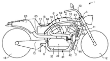
図1ないし図3は、本発明の第1の実施形態による鞍乗型車両を示している。具体的には、図1は本発明の第1の実施形態による鞍乗型車両を右から見た図であり、図2は、当該鞍乗型車両を左から見た図であり、図3は当該鞍乗型車両を上から見た図である。なお、以下の実施形態の説明において、前、後、左、右、上、下の各方向は、鞍乗型車両の運転シートに着座した運転者を基準にする。
(First embodiment)
(Basic configuration of saddle riding type vehicle)
1 to 3 show a straddle-type vehicle according to a first embodiment of the present invention. Specifically, FIG. 1 is a diagram of the saddle riding type vehicle according to the first embodiment of the present invention as seen from the right, and FIG. 2 is a diagram of the saddle riding type vehicle as seen from the left. These are the figures which looked at the said saddle riding type vehicle from the top. In the following description of the embodiments, the front, rear, left, right, up, and down directions are based on the driver seated on the driving seat of the saddle riding type vehicle.
図1に示すように、本発明の第1の実施形態による鞍乗型車両1は例えば自動二輪車である。鞍乗型車両1の車体フレーム2は、ヘッドパイプ3、一対のメインフレーム4、一対のダウンチューブ5、および一対のピボットフレーム6を備えている。ヘッドパイプ3は、鞍乗型車両1の前部かつ上部に配置されている。一対のメインフレーム4は、図3に示すように、ヘッドパイプ3から左右に拡開しつつ、後方へ伸長している。一対のダウンチューブ5は、図1および図2に示すように、ヘッドパイプ3から後方に傾斜しつつ下方へ伸長した後、湾曲し、その後、ほぼ水平方向に後方へ伸長している。ここで、図3、図7および図8中のSは、鞍乗型車両1の左右方向のちょうど中間を前後方向に貫く基準線を示している。一対のダウンチューブ5は、図7に示すように、この基準線Sの左側および右側にそれぞれ位置し、互いに所定距離離間し、かつ互いに平行に配置されている。また、各ピボットフレーム6は、図1および図2に示すように、メインフレーム4の後端部とダウンチューブ5の後端部との間を上下方向に伸長している。また、図示しないが、車体フレーム2は、各メインフレーム4の後端側から後方へ伸長するシートレール、並びにメインフレーム4の間、ダウンチューブ5の間、およびピボットフレーム6の間を連結するブリッジフレーム等を備えている。
As shown in FIG. 1, the saddle riding
また、図1に示すように、車体フレーム2のヘッドパイプ3には、ステアリングシャフト(図示せず)が挿入され、ステアリングシャフトにはブラケットを介してフロントフォーク11の上端側が支持され、フロントフォーク11の下端側には前輪12が支持されている。また、ステアリングシャフトには、ブラケットを介してハンドル13が設けられている。一方、各ピボットフレーム6には、スイングアーム15の前端側が支持され、スイングアーム15の後端側には後輪16が支持されている。また、前輪12と後輪16との間に位置し、一対のメインフレーム4、一対のダウンチューブ5、および一対のピボットフレーム6により囲まれた空間内にはエンジン31が設けられている。エンジン31は、エンジンマウントを介して、各メインフレーム4および各ダウンチューブ5等に固定されている。さらに、エンジン31の後方かつ上方には、運転者が着座する運転シート18が設けられ、運転シート18の下方には燃料タンク17が設けられている。また、運転シート18の後方には、排気音を低減するサイレンサ20が設けられている。また、エンジン31の下部後方には、図3に示すように、運転者が足をかける左右一対のステップ19が設けられている。
As shown in FIG. 1, a steering shaft (not shown) is inserted into the
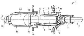
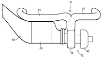
図4は、鞍乗型車両1に設けられたエンジン31、過給機42、インタークーラ47、サージタンク59、排気マニホールド61および送出配管65等を右から見た図であり、図5は、これらを図4中の矢示V−V方向から見た図である。また、図6は、鞍乗型車両1に設けられたエアクリーナ41、過給機42、サージタンク59、燃料タンク17およびサイレンサ20を上から見た図である。
4 is a view of the
図4に示すように、エンジン31は、前、後に配置された一対のシリンダを有する横置きV型2気筒のエンジンである。すなわち、エンジン31は、クランクケース32と、クランクケース32の上部前側に配置された前側シリンダ33と、クランクケース32の上部後ろ側に配置された後ろ側シリンダ35とを備えている。前側シリンダ33は、前方に傾斜しており、前側シリンダ33の上部にはシリンダヘッド34が設けられている。また、後ろ側シリンダ35は、後方に傾斜しており、後ろ側シリンダ35の上部にはシリンダヘッド36が設けられている。
As shown in FIG. 4, the
また、クランクケース32の底部には、エンジンオイルを貯留するオイル貯留部としてのオイルパン37が設けられている。鞍乗型車両1には、クランクケース32の底側に設けられたオイルパン37にエンジンオイルを貯留し、そのエンジンオイルをポンプで汲み上げて、エンジン31の各部に圧送するウェットサンプ方式が採用されている。
An
エンジン31の理想状態時(例えば整備によりエンジンオイルの貯留量を整えた直後)には、所定量のエンジンオイルがオイルパン37に貯留されている。図4中のLは、理想状態時に所定量のエンジンオイルがオイルパン37に貯留された状態におけるエンジンオイルの油面の位置、すなわちオイルレベルを示している。オイルレベルLは、オイルパン37の底面よりも高く、かつエンジン31のクランクシャフトの軸線Xよりも低い。
When the
(鞍乗型車両の吸気系)
また、鞍乗型車両1には、燃料燃焼用の空気を浄化するエアクリーナ41が設けられている。図5または図6に示すように、エアクリーナ41は、エンジン31の左方に配置されている。
(Intake system for saddle-ride type vehicles)
In addition, the saddle riding
また、鞍乗型車両1には、エアクリーナ41により浄化された空気を圧縮する過給機42が設けられている。過給機42は、エアクリーナ41により浄化された空気を圧縮するコンプレッサ部43と、コンプレッサ部43を駆動するタービン部44とを備えている。
The saddle riding
図4に示すように、過給機42は、エンジン31の前側シリンダ33の左右方向一側、具体的には前側シリンダ33の右方に配置されている。より具体的には、過給機42は、鞍乗型車両1の側面視において、前側シリンダ33と重なる位置に配置されている。また、過給機42は、オイルレベルLよりも高い位置に配置されている。また、過給機42は、クランクシャフトの軸線Xよりも高い位置に配置されている。また、過給機42は、コンプレッサ部43がタービン部44よりも前側となるように配置されている。また、過給機42は、左右方向においてエアクリーナ41の反対側に配置されている。
As shown in FIG. 4, the
過給機42がエンジン31の側方に配置されているので、例えば上記特許文献3の第2図に示されているような、過給機がエンジンの前方に配置された従来の鞍乗型車両と比較して、鞍乗型車両1の走行中に、例えば回転する前輪12によって巻き上げられた飛び石、砂、その他地面に散在した物が過給機42に当たり難い。したがって、過給機42を飛び石等から保護することができる。また、過給機42がエンジン31の側方に配置されているので、過給機がエンジンの前方または後方に配置された従来の鞍乗型車両と比較して、鞍乗型車両1を前後方向に小さくすることができる。
Since the
また、過給機42が、鞍乗型車両1の側面視において、前側シリンダ33と重なる位置に配置されているので、例えば上記特許文献1の第1図に示されているような、過給機がエンジンの後方に配置された従来の鞍乗型車両と比較して、運転シート18に着座した運転者の足と過給機42との間に長い距離が確保されており、過給機42が各ステップ19から大きく離れている。過給機42のタービン部44は、エンジン31の排気を利用してタービンホイールを回転させるため、排気の熱により高温となる。また、過給機42のコンプレッサ部43は空気を圧縮するので高温となる。過給機42と運転者の足との間の距離を長くすることで、過給機42から発せられる高温の熱が運転者の足に伝わることを防止でき、運転者を保護することができる。
Further, since the
また、過給機42は、オイルレベルLよりも高い位置に配置されているので、過給機42へ供給したエンジンオイルを自由落下によりオイルパン37へ戻すことができる。すなわち、過給機42は、タービン部44に設けられたタービンホイールを回転させると共に、コンプレッサ部43に設けられたコンプレッサインペラを回転させるためのベアリングを備えている。鞍乗型車両1は、この過給機42のベアリングを潤滑し、または冷却するために、オイルパン37に貯留されたエンジンオイルをポンプで汲み上げ、エンジン31の各部だけでなく、過給機42のベアリングへ供給する機構を備えている。過給機42が、オイルパン37に貯留されたエンジンオイルのオイルレベルLよりも高い位置に配置されているので、過給機42のベアリングに供給されたエンジンオイルを重力によりオイルパン37へ落とすことができる。したがって、過給機42へ供給したエンジンオイルを回収するポンプを別途設ける必要がないので、鞍乗型車両1の部品点数を減らして製造コストを削減することができると共に、鞍乗型車両1の軽量化を図ることができる。
Further, since the
また、エアクリーナ41と過給機42との間には、エアクリーナ41により浄化された空気を過給機42のコンプレッサ部43へ送るインレット配管45が設けられている。インレット配管45は、左右方向に伸長し、図5に示すように、ラジエータ46とインタークーラ47との間に形成された空間に配置されている。インレット配管45の左端はエアクリーナ41の排出口41Aに接続され、インレット配管45の右端はコンプレッサ部43の吸入口43Aに接続されている。
An
また、図4に示すように、鞍乗型車両1において、エンジン31の前方には、エンジン31を冷却する冷却水を、走行時に受ける風等を利用して冷却するラジエータ46、および過給機42により圧縮されて高温となった空気を、走行時に受ける風等を利用して冷却するインタークーラ47が設けられている。ラジエータ46およびインタークーラ47は、左右一対のダウンチューブ5において後方に傾斜しつつ上下方向に伸長している部分の前側に配置されている。また、ラジエータ46およびインタークーラ47は、一対のダウンチューブ5の当該部分に沿うように、上下方向に並んで配置されている。また、インタークーラ47はラジエータ46よりも上側に配置されている。また、図5に示すように、ラジエータ46およびインタークーラ47はいずれも鞍乗型車両1の左右方向中間部に配置されている。
As shown in FIG. 4, in the saddle riding
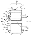
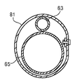
ここで、図7は、インタークーラ47を、ダウンチューブ5、エアクリーナ41および過給機42と共に示している。図7に示すように、インタークーラ47は、複数の空気通路およびこれら空気通路間に配置された放熱フィンを有するコア48と、コア48の下側に配置され、過給機42のコンプレッサ部43から送られた空気をコア48へ供給するロワーチューブ49と、コア48の上側に配置され、コア48を通って冷却された空気をスロットルボディ54(図4参照)に向けて排出するアッパーチューブ51を備えている。
Here, FIG. 7 shows the
また、ロワーチューブ49には、コンプレッサ部43からの空気をロワーチューブ49内へ流入させる吸入部50が設けられている。吸入部50は、ロワーチューブ49の後部の左右方向中間部に配置されており、ダウンチューブ5間を通って後方へ張り出している。また、吸入部50とコンプレッサ部43の排出口43Bとの間には両者間を接続するアウトレット配管53が設けられている。
Further, the
また、アッパーチューブ51には、コア48からアッパーチューブ51内へ流出した空気をスロットルボディ54に向けて排出する排出部52が設けられている。排出部52は、アッパーチューブ51の右部に配置されている。
In addition, the
また、図4に示すように、鞍乗型車両1において、エンジン31の前側シリンダ33のシリンダヘッド34の上方には、スロットルボディ54が設けられている。また、スロットルボディ54の内部にはスロットルバルブ55が設けられている。
As shown in FIG. 4, in the saddle riding
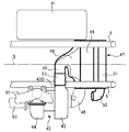
また、インタークーラ47とスロットルボディ54との間には、インタークーラ47により冷却された空気をスロットルボディ54へ送るインタークーラアウト配管56が設けられている。ここで、図8はインタークーラアウト配管56、スロットルボディ54、サージタンク59等を示している。図8に示すように、インタークーラアウト配管56の前端は、インタークーラ47のアッパーチューブ51に設けられた排出部52に接続され、インタークーラアウト配管56の後端は、スロットルボディ54において、スロットルバルブ55よりも上流側に位置する開口部に接続されている。
An intercooler out
また、図4に示すように、鞍乗型車両1には、スロットルバルブ55が閉じられたときにコンプレッサ部43とスロットルバルブ55との間の余剰圧力をコンプレッサ部43の上流側に逃がすためのエアバイパス配管57およびエアバイパスバルブ58が設けられている。エアバイパス配管57は、コンプレッサ部43の下流側に位置するインタークーラアウト配管56と、コンプレッサ部43の上流側に位置するインレット配管45との間を接続している。また、エアバイパスバルブ58は、エアバイパス配管57を開閉するバルブである。
In addition, as shown in FIG. 4, the saddle riding
また、図4に示すように、鞍乗型車両1において、エンジン31の前側シリンダ33および後ろ側シリンダ35の上方には、インタークーラ47により冷却され、スロットルボディ54を通って送られた空気を一時的に貯えるサージタンク59が設けられている。また、サージタンク59はスロットルボディ54の後方に配置されている。また、サージタンク59の前端部に設けられた吸入口59Aには、スロットルボディ54において、スロットルバルブ55よりも下流側に位置する開口部がホースまたはパイプ等の配管を介して接続されている。スロットルボディ54を通って送られた空気は、吸入口59Aからサージタンク59内へ流入する。
In addition, as shown in FIG. 4, in the saddle riding
また、サージタンク59の下部に設けられた排気口(図示せず)は、前側シリンダ33のシリンダヘッド34に設けられた吸気ポート、および後ろ側シリンダ35のシリンダヘッド36に設けられた吸気ポートに、それぞれ吸気管60を介して接続されている。サージタンク59内に一時的に貯えられた空気は、サージタンク59の排気口から吸気管60を通って2つの吸気ポートへ供給される。また、図示しないが、各吸気管60にはインジェクタが設けられている。
An exhaust port (not shown) provided in the lower portion of the
鞍乗型車両1における吸気系の動作は次の通りである。すなわち、外部からエアクリーナ41に取り込まれた空気は、エアクリーナ41により浄化される。浄化された空気はインレット配管45を通って過給機42のコンプレッサ部43へ送られ、コンプレッサ部43により圧縮される。圧縮された空気はアウトレット配管53を通り、さらにインタークーラ47のロワーチューブ49を通ってインタークーラ47のコア48へ送られ、コア48により冷却される。冷却された空気は、インタークーラ47のアッパーチューブ51、インタークーラアウト配管56、およびスロットルボディ54を通ってサージタンク59へ送られ、サージタンク59において一時的に貯えられる。さらに、サージタンク59に一時的に貯えられることにより整流された空気は、吸気管60を通って前側シリンダ33および後ろ側シリンダ35にそれぞれ供給される。
The operation of the intake system in the saddle riding
(鞍乗型車両の排気系)
一方、鞍乗型車両1には、図4に示すように、エンジン31の前側シリンダ33および後ろ側シリンダ35から排出される排気を過給機42のタービン部44に供給する排気マニホールド61が設けられている。また、鞍乗型車両1には、前側シリンダ33および後ろ側シリンダ35からタービン部44に供給された排気をタービン部44からサイレンサ20(図1参照)へ送り出す送出配管65が設けられている。タービン部44は、前側シリンダ33および後ろ側シリンダ35からの排気の熱エネルギーを利用して、タービンホイールを回転させ、コンプレッサ部43を駆動する。
(Exhaust system of saddle riding type vehicle)
On the other hand, as shown in FIG. 4, the saddle riding
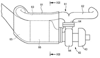
ここで、図9は、過給機42、排気マニホールド61および送出配管65等を示している。図9に示すように、排気マニホールド61は、前側シリンダ33から排出される排気をタービン部44に供給する第1の排気通路を形成する前側排気管62と、後ろ側シリンダ35から排出される排気をタービン部44に供給する第2の排気通路を形成する後ろ側排気管63とを備えている。排気マニホールド61は、前側排気管62と後ろ側排気管63とを鋳造により一体に成型し、または前側排気管62と後ろ側排気管63とを溶接により結合することにより形成されている。
Here, FIG. 9 shows the
前側排気管62の一端は、前側シリンダ33のシリンダヘッド34の前部に設けられた排気ポートに接続されている。前側排気管62は、シリンダヘッド34の排気ポートから前方へ僅かに伸長した後、湾曲し、その後、右方へ伸長した後、湾曲し、その後、前側シリンダ33の右方を後方へ伸長している。
One end of the
また、後ろ側排気管63の一端は、後ろ側シリンダ35のシリンダヘッド36の後部に設けられた排気ポートに接続されている。後ろ側排気管63は、シリンダヘッド36の排気ポートから後方へ僅かに伸長した後、湾曲し、その後、右方へ伸長した後、湾曲し、その後、後ろ側シリンダ35の右方を前方へ伸長し、さらに、前側シリンダ33の右方を前方へ伸長している。
Further, one end of the
前側排気管62の他端側と、後ろ側排気管63の他端側とは、過給機42のタービン部44の上方で出会い、互いに結合して1本の結合管部64となって下方へ伸長し、タービン部44の上部に形成された吸込口44Aに達している。そして、排気マニホールド61の結合管部64とタービン部44の吸込口44Aとは、排気マニホールド61の結合管部64の端部に設けられたフランジ64Aと、タービン部44の吸入口44Aの周囲に設けられたフランジ44Bとをボルト等により固定することにより接続されている。このように、排気マニホールド61、すなわち、前側排気管62および後ろ側排気管63は、過給機42のタービン部44よりも高い位置に配置されており、タービン部44の上方からタービン部44に接続されている。
The other end side of the
一方、送出配管65は、過給機42のタービン部44から排出された排気をエンジン31の後方へ送出する第3の排気通路を形成する配管である。送出配管65の前端は、図9に示すように、タービン部44の排出口44Cに接続されている。具体的には、送出配管65の前端とタービン部44の排出口44Cとは、送出配管65の前端部に設けられたフランジ65Aと、タービン部44の排出口44Cの周囲に設けられたフランジ44Dとをボルト等により固定することにより接続されている。
On the other hand, the
また、送出配管65は、タービン部44の排出口44Cから、エンジン31の右方を、エンジン31の後方へ伸長している。具体的には、送出配管65の前端側は、後ろ側排気管63の直ぐ下側に位置し、後ろ側排気管63に沿って伸長している。すなわち、後ろ側排気管63と送出配管65とは、エンジン31の右方において、互いに隣接し、かつ同じ方向(前後方向)に互いに平行に伸長している。より具体的には、送出配管65は、タービン部44の排出口44Cの僅かに後方へ進んだ位置から、後ろ側シリンダ35の後部を超え、後ろ側排気管63が後ろ側シリンダ35の排気ポートに向かって左方へ湾曲し始める位置に達するまでの間、後ろ側排気管63に沿い、後ろ側排気管63に隣接している。
Further, the
さらに、送出配管65の後端側は、エンジン31の右後方を、鞍乗型車両1の後部へ向かって伸長した後、サイレンサ20に接近するように湾曲し、送出配管65の後端はサイレンサ20に接続されている。
Further, the rear end side of the
また、送出配管65には、排気に含まれる一酸化炭素、炭化水素、窒素酸化物等の有害な物質を無害な物質に変換する触媒66が設けられている。触媒66は、送出配管65の前端側であって後ろ側排気管63に隣接する部分に配置されている。
Further, the
鞍乗型車両1における排気系の動作は次の通りである。すなわち、前側シリンダ33および後ろ側シリンダ35から排出された排気は、排気マニホールド61における前側排気管62および後ろ側排気管63を通って過給機42のタービン部44へ送られた後、タービン部44から送出配管65を通ってサイレンサ20へ送られ、サイレンサ20から外部へ排出される。また、過給機42において、タービン部44に設けられたタービンホイールは、前側排気管62および後ろ側排気管63を通ってタービン部44へ送られた排気の熱エネルギー(排気の圧力)により回転する。これに伴い、コンプレッサ部43に設けられたコンプレッサインペラが回転する。これにより、インレット配管45を通ってコンプレッサ部43に送られた空気の圧縮が行われる。
The operation of the exhaust system in the saddle riding
ここで、鞍乗型車両1において、過給機42のタービン部44が前側シリンダ33の右方に配置されており、タービン部44と前側シリンダ33とが互いに接近している。これにより、前側排気管62を短くすることができる。したがって、前側排気管62を流通する排気の熱エネルギーの低下を抑えることができる。
Here, in the saddle riding
これに対し、タービン部44と前側排気管62との位置関係と比較して、タービン部44と後ろ側排気管とは互いに離れている。この結果、後ろ側排気管63は、前側排気管62と比較して長い。しかしながら、送出配管65の前端側が、後ろ側排気管63の下側を、後ろ側排気管63に沿って伸長しているので、送出配管65を流通する排気の熱を利用して、後ろ側排気管63を流通する排気の熱エネルギーの低下を抑制することができる。すなわち、送出配管65にはタービン部44から排出された高温の排気が流通する。送出配管65を後ろ側排気管63に沿うように配置し、後ろ側排気管63と送出配管65とを広い範囲において互いに隣接させることにより、送出配管65を流通する排気の熱を利用して、後ろ側排気管63を流通する排気の温度低下を抑えることができ、当該排気の熱エネルギーの低下を抑制することができる。
On the other hand, compared with the positional relationship between the
このように、前側シリンダ33および後ろ側シリンダ35のそれぞれからタービン部44へ供給される排気の熱エネルギーの低下を抑制することができるので、タービン部44の駆動に関するエネルギー効率を良くすることができる。
Thus, since the fall of the thermal energy of the exhaust gas supplied from each of the
また、後ろ側排気管63に送出配管65を沿わせて後ろ側排気管63を流通する排気の温度低下を抑制することにより、前側排気管62と後ろ側排気管63との長さが異なるにもかかわらず、前側シリンダ33の排気温度と後ろ側シリンダ35の排気温度との差を小さくすることができる。これにより、前側シリンダ33と後ろ側シリンダ35との間で、燃調または点火時期の設定を互いに近づけることができ、エンジン出力の低下を抑えることができる。
Further, the lengths of the
また、鞍乗型車両1の送出配管65において、触媒66が後ろ側排気管63に隣接する位置に配置されているので、後ろ側排気管63を流通する排気の熱を利用して触媒66の温度を迅速に高めることができる。したがって、例えば冷間始動時において触媒66の温度がその活性温度に達する時間を短くすることができる。
Further, in the
また、鞍乗型車両1において、排気マニホールド61、すなわち、前側排気管62および後ろ側排気管63は、上述したように、過給機42のタービン部44よりも高い位置に配置されており、タービン部44の上方からタービン部44に接続されている。ここで、図10は、鞍乗型車両1の前面視における過給機42のタービン部44、およびタービン部44に接続された排気マニホールド61を示している。図10に示すように、鞍乗型車両1の前面視において、排気マニホールド61のタービン部44への接続角度αは30度以上150度以下の範囲内であることが好ましい。
Further, in the saddle riding
すなわち、接続角度αが30度未満である場合には、排気マニホールド61を過給機42のタービン部44に接続するために、過給機42を前側シリンダ33から右方へ離さなければならない。すなわち、過給機42と前側シリンダ33との間に排気マニホールド61を配管するスペースを確保しなければならないため、過給機42を前側シリンダ33から離さなければならない。その結果、重量物である過給機42が鞍乗型車両1の左右方向の中心から離れるので、車両の左右方向のバランスをとることが困難となり、車両の保針性が悪化する。
That is, when the connection angle α is less than 30 degrees, the
一方、接続角度αが150度よりも大きい場合には、排気マニホールド61が遠回りして過給機42のタービン部44に接続されることとなる。それゆえ、排気マニホールド61における前側排気管62および後ろ側排気管63が長くなり、前側排気管62および後ろ側排気管63を流通する排気の熱エネルギーが低下する。また、接続角度αが150度よりも大きい場合には、排気マニホールド61が鞍乗型車両1の右外側に張り出してしまい、車幅が大きくなる。
On the other hand, when the connection angle α is larger than 150 degrees, the
接続角度αを30度以上150度以下の範囲内とすることにより、過給機42を前側シリンダ33に接近させて車両の保針性を良くすることができ、また、排気マニホールド61における前側排気管62および後ろ側排気管63を短くし、前側排気管62および後ろ側排気管63を流通する排気の熱エネルギーの低下を抑えることができ、さらに、排気マニホールド61が鞍乗型車両1の外側に張り出すことを防止し、車幅を小さくすることができる。
By setting the connection angle α within the range of 30 degrees or more and 150 degrees or less, the
(第2の実施形態)
図11は、本発明の第2の実施形態による鞍乗型車両における過給機、排気マニホールドおよび送出配管を示している。なお、図11において、上述した本発明の第1の実施形態の構成要素と同一の構成要素には同一の符号を付し、それらの説明を省略する。この点は、後述する本発明の第3の実施形態を示す図12および図13、本発明の第4の実施形態を示す図14、本発明の第5の実施形態を示す図15および図16、および本発明の第6の実施形態を示す図17についても同様である。
(Second Embodiment)
FIG. 11 shows a supercharger, an exhaust manifold, and a delivery pipe in a saddle-ride type vehicle according to the second embodiment of the present invention. In FIG. 11, the same reference numerals are given to the same components as those of the first embodiment of the present invention described above, and the description thereof is omitted. 12 and 13 showing a third embodiment of the present invention, which will be described later, FIG. 14 showing a fourth embodiment of the present invention, and FIGS. 15 and 16 showing a fifth embodiment of the present invention. This also applies to FIG. 17 showing the sixth embodiment of the present invention.
図11に示すように、本発明の第2の実施形態による鞍乗型車両においては、排気マニホールド71が、前側シリンダ33から排出される排気をタービン部73に供給する第1の排気通路を形成する前側排気管74と、後ろ側シリンダ35から排出される排気をタービン部73に供給する第2の排気通路を形成する後ろ側排気管75と、過給機72のタービン部73とを、鋳造により一体に成型し、またはこれらを溶接により結合することにより形成されている。これにより、前側排気管74、後ろ側排気管75およびタービン部73の熱容量を低減することができる。また、排気系の部品点数を減らすことができ、また、鞍乗型車両1の軽量化を図ることができる。
As shown in FIG. 11, in the saddle riding type vehicle according to the second embodiment of the present invention, the
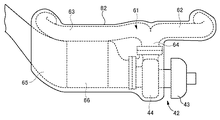
(第3の実施形態)
図12は、本発明の第3の実施形態による鞍乗型車両における過給機、排気マニホールド、送出配管および保温カバーを示している。また、図13は、図12中の矢示XIII−XIII方向から見た後ろ側排気管、送出配管および保温カバーの断面を示している。
(Third embodiment)
FIG. 12 shows a supercharger, an exhaust manifold, a delivery pipe, and a heat insulation cover in a saddle riding type vehicle according to the third embodiment of the present invention. FIG. 13 shows a cross section of the rear exhaust pipe, the delivery pipe, and the heat insulation cover as seen from the direction of arrows XIII-XIII in FIG.
図12に示すように、本発明の第3の実施形態による鞍乗型車両においては、後ろ側排気管63および送出配管65の前端側が保温カバー81によりまとめて覆われている。保温カバー81は例えばステンレス等の金属により形成されている。また、保温カバー81は、後ろ側排気管63の大部分と、送出配管65において後ろ側排気管63に沿って伸長している部分を覆っている。また、保温カバー81は、図13に示すように、後ろ側排気管63と送出配管65の前端側をまとめて包み込むように、それらの全周を包囲している。また、保温カバー81は、送出配管65に設けられた触媒66をも覆っている。
As shown in FIG. 12, in the saddle-ride type vehicle according to the third embodiment of the present invention, the
本発明の第3の実施形態による鞍乗型車両によれば、後ろ側排気管63を流通する排気の熱が、後ろ側排気管63の外周面から大気へ放出されることを保温カバー81により抑えることができる。また、これと同時に、送出配管65を流通する排気の熱が、送出配管65の外周面から大気へ放出されることを保温カバー81により抑えることができる。したがって、送出配管65を流通する排気の熱を利用して、後ろ側排気管63を流通する排気の温度低下を抑える効果を高めることができる。さらに、触媒66が保温カバー81により覆われているので、冷間始動時において、触媒66の温度がその活性温度に達する時間を、より一層短くすることができる。また、後ろ側排気管63または送出配管65から運転者に伝わる熱を保温カバー81により抑えることができる。
According to the saddle riding type vehicle according to the third embodiment of the present invention, the
(第4の実施形態)
図14は、本発明の第4の実施形態による鞍乗型車両における過給機、排気マニホールド、送出配管および保温カバーを示している。図14に示すように、本発明の第4の実施形態による鞍乗型車両においては、過給機42のタービン部44、前側排気管62、後ろ側排気管62、および送出配管65の前端側が保温カバー82によりまとめて覆われている。
(Fourth embodiment)
FIG. 14 shows a supercharger, an exhaust manifold, a delivery pipe, and a heat insulation cover in a saddle riding type vehicle according to the fourth embodiment of the present invention. As shown in FIG. 14, in the saddle riding type vehicle according to the fourth embodiment of the present invention, the front end side of the
本発明の第4の実施形態による鞍乗型車両によれば、前側排気管62を流通する排気の熱、後ろ側排気管63を流通する排気の熱、タービン部44を通る排気の熱、および送出配管65を流通する排気の熱が大気へ放出されることを保温カバー82により抑えることができる。また、保温カバー82で覆う範囲を拡張することにより、保温カバー82の保温効果を高めることができる。したがって、前側排気管62を流通する排気の温度低下を抑える効果を高めることができ、また、タービン部44を通る排気の温度低下を抑えることができる。さらに、送出配管65を流通する排気の熱を利用して、後ろ側排気管63を流通する排気の温度低下を抑える効果をより一層高めることができる。
According to the saddle riding type vehicle according to the fourth embodiment of the present invention, the heat of the exhaust flowing through the
(第5の実施形態)
図15は、本発明の第5の実施形態による鞍乗型車両における過給機、前側排気ユニットおよび後ろ側排気ユニットを示している。図16は、当該鞍乗型車両における前側排気ユニットおよび後ろ側排気ユニットを示している。
(Fifth embodiment)
FIG. 15 shows a supercharger, a front exhaust unit, and a rear exhaust unit in a saddle riding type vehicle according to a fifth embodiment of the present invention. FIG. 16 shows a front exhaust unit and a rear exhaust unit in the saddle riding type vehicle.
図15または図16に示すように、本発明の第5の実施形態による鞍乗型車両は、過給機92のタービン部93と、前側シリンダ33からの排気をタービン部93に供給する第1の排気通路を形成する前側排気管94とが鋳造により一体に成型された前側排気ユニット91を備えている。さらに、当該鞍乗型車両は、後ろ側シリンダ35からの排気をタービン部93に供給する後ろ側排気通路97(第2の排気通路)と、タービン部93から排出された排気をエンジン31の後方へ送出する送出通路98(第3の排気通路)とが鋳造により一体に成型された排気通路集合体としての後ろ側排気ユニット96を備えている。なお、図15においては、前側排気ユニット91については右側の外面を示し、後ろ側排気ユニット96については断面を示している。
As shown in FIG. 15 or FIG. 16, the saddle riding type vehicle according to the fifth embodiment of the present invention is the first to supply the
前側排気ユニット91と後ろ側排気ユニット96とは、前側排気ユニット91に形成されたフランジ91Aと、後ろ側排気ユニット96に形成されたフランジ96Aとをボルト等を用いて固定することにより接続されている。また、送出通路98には触媒99が設けられている。
The
本発明の第5の実施形態による鞍乗型車両によれば、後ろ側排気通路97と送出通路98とを一体に成型したことにより、後ろ側排気通路97と送出通路98とを互いにより接近させ、さらには互いに密着させることができる。また、後ろ側排気通路97と送出通路98とが互いに接近する範囲を広くすることができる。また、後ろ側排気通路97と送出通路98との境界部分とその周辺部分を、後ろ側排気ユニット96の内部に形成し、外部に露出しないようにすることにより、後ろ側排気通路97と送出通路98との境界部分またはその周辺部分から排気の熱が大気へ放出されることを抑制することができる。これにより、送出通路98を流通する排気の熱を利用して、後ろ側排気通路97を流通する排気の温度低下を抑える効果を高めることができる。また、後ろ側排気通路97と送出通路98とが一体成型された後ろ側排気ユニット96の内部に触媒99を配置することにより、触媒99の温度がその活性温度に達する時間を、より一層短くすることができる。さらに、過給機92のタービン部93、前側排気管94、後ろ側排気通路97および送出通路98を、前側排気ユニット91と後ろ側排気ユニット96の2つの部品により形成することができるので、排気系の部品点数を削減することができる。
According to the saddle-ride type vehicle according to the fifth embodiment of the present invention, the
なお、後ろ側排気ユニット96において、後ろ側排気通路97と送出通路98とを一体化する方法は、鋳造による成型に限らず、後ろ側排気通路97を形成する配管と送出通路98を形成する配管とを溶接により互いに接合する方法でもよい。前側排気ユニット91において、タービン部93と前側排気管94とを一体化する方法についても同様である。
In the
(第6の実施形態)
図17は、本発明の第6の実施形態による鞍乗型車両における過給機および排気ユニットを示している。
(Sixth embodiment)
FIG. 17 shows a supercharger and an exhaust unit in a saddle riding type vehicle according to the sixth embodiment of the present invention.
図17に示すように、本発明の第6の実施形態による鞍乗型車両は、前側排気通路104(第1の排気通路)と、後ろ側排気通路105(第2の排気通路)と、送出通路107(第3の排気通路)とが鋳造により一体に成型された排気通路集合体としての排気ユニット103を備えている。また、送出通路107には触媒108が設けられている。
As shown in FIG. 17, the saddle riding type vehicle according to the sixth embodiment of the present invention includes a front exhaust passage 104 (first exhaust passage), a rear exhaust passage 105 (second exhaust passage), and a delivery. An
本発明の第6の実施形態による鞍乗型車両によれば、上述した本発明の第5の実施形態と同様の作用効果を得ることができる。また、前側排気通路104、後ろ側排気通路105および送出通路107を一体化することにより、部品点数のより一層の削減を図ることができる。
According to the saddle riding type vehicle according to the sixth embodiment of the present invention, the same operational effects as those of the above-described fifth embodiment of the present invention can be obtained. Further, by integrating the
なお、排気ユニット103において、前側排気通路104、後ろ側排気通路105および送出通路107を一体化する方法は、鋳造による成型に限らず、前側排気通路104を形成する配管、後ろ側排気通路105を形成する配管、および送出通路107を形成する配管を溶接によりそれぞれ接合する方法でもよい。
In the
また、上述した各実施形態では、鞍乗型車両として自動二輪車を例にあげたが、本発明は他の種類の鞍乗型車両にも適用することができる。また、本発明は、3気筒以上のV型エンジンにも適用することができる。また、本発明は、前側シリンダがクランクケースから前方へ水平方向に伸長し、後ろ側シリンダがクランクケースから上方へ垂直方向に伸長する、いわゆるL型エンジンにも適用することができる。 In each of the above-described embodiments, a motorcycle is taken as an example of a saddle riding type vehicle. However, the present invention can be applied to other types of saddle riding type vehicles. The present invention can also be applied to a V-type engine having three or more cylinders. The present invention can also be applied to a so-called L-type engine in which the front cylinder extends in the horizontal direction forward from the crankcase and the rear cylinder extends in the vertical direction upward from the crankcase.
また、本発明は、請求の範囲および明細書全体から読み取ることのできる発明の要旨または思想に反しない範囲で適宜変更可能であり、そのような変更を伴う鞍乗型車両もまた本発明の技術思想に含まれる。 Further, the present invention can be appropriately changed without departing from the spirit or idea of the invention which can be read from the claims and the entire specification, and a straddle-type vehicle accompanied with such a change is also applicable to the technology of the present invention. Included in thought.
1 鞍乗型車両
31 エンジン
33 前側シリンダ
34 シリンダヘッド
35 後ろ側シリンダ
36 シリンダヘッド
42、72、92 過給機
43 コンプレッサ部
44、73、93 タービン部
44A 吸入口
44C 排出口
61、71 排気マニホールド
62、74、94 前側排気管
63、75 後ろ側排気管
64 結合管部
65 送出配管
66、99、108 触媒
81、82 保温カバー
91 前側排気ユニット
104 前側排気通路(第1の排気通路)
96 後ろ側排気ユニット(排気通路集合体)
97、105 後ろ側排気通路(第2の排気通路)
98、107 送出通路(第3の排気通路)
103 排気ユニット(排気通路集合体)
1 straddle-
96 Rear exhaust unit (exhaust passage assembly)
97, 105 Rear exhaust passage (second exhaust passage)
98, 107 Delivery passage (third exhaust passage)
103 Exhaust unit (exhaust passage assembly)
Claims (6)
前記前側シリンダおよび前記後ろ側シリンダからの排気を用いて駆動し、燃料燃焼用の空気を圧縮する過給機と、
前記前側シリンダと前記過給機とを接続し、前記前側シリンダからの排気を前記過給機に供給する第1の排気通路と、
前記後ろ側シリンダと前記過給機とを接続し、前記後ろ側シリンダからの排気を前記過給機に供給する第2の排気通路と、
前記過給機に接続され、前記過給機から排出された排気を前記V型エンジンの後方へ送出する第3の排気通路とを備え、
前記過給機は前記前側シリンダの左右方向一側に配置され、
前記第2の排気通路は前記後ろ側シリンダから前記過給機に向かって前記V型エンジンの左右方向一側を通って伸長し、
前記第3の排気通路は前記V型エンジンの左右方向一側において前記過給機から前記V型エンジンの後方へ向かって前記第2の排気通路に沿って伸長していることを特徴とする鞍乗型車両。 A V-type engine having at least a pair of cylinders including a front cylinder and a rear cylinder disposed respectively in front and rear;
A turbocharger that is driven using exhaust from the front and rear cylinders and compresses fuel combustion air;
A first exhaust passage for connecting the front cylinder and the supercharger, and supplying exhaust from the front cylinder to the supercharger;
A second exhaust passage for connecting the rear cylinder and the supercharger, and supplying exhaust from the rear cylinder to the supercharger;
A third exhaust passage connected to the supercharger and sending exhaust discharged from the supercharger to the rear of the V-type engine;
The supercharger is disposed on one side of the front cylinder in the left-right direction,
The second exhaust passage extends from the rear cylinder toward the turbocharger through one side in the left-right direction of the V-type engine,
The third exhaust passage extends along the second exhaust passage from the supercharger toward the rear of the V-type engine on one side in the left-right direction of the V-type engine. Ride type vehicle.
Priority Applications (1)
| Application Number | Priority Date | Filing Date | Title |
|---|---|---|---|
| JP2016045933A JP6607094B2 (en) | 2016-03-09 | 2016-03-09 | Saddle riding vehicle |
Applications Claiming Priority (1)
| Application Number | Priority Date | Filing Date | Title |
|---|---|---|---|
| JP2016045933A JP6607094B2 (en) | 2016-03-09 | 2016-03-09 | Saddle riding vehicle |
Publications (2)
| Publication Number | Publication Date |
|---|---|
| JP2017160841A true JP2017160841A (en) | 2017-09-14 |
| JP6607094B2 JP6607094B2 (en) | 2019-11-20 |
Family
ID=59856698
Family Applications (1)
| Application Number | Title | Priority Date | Filing Date |
|---|---|---|---|
| JP2016045933A Active JP6607094B2 (en) | 2016-03-09 | 2016-03-09 | Saddle riding vehicle |
Country Status (1)
| Country | Link |
|---|---|
| JP (1) | JP6607094B2 (en) |
Cited By (3)
| Publication number | Priority date | Publication date | Assignee | Title |
|---|---|---|---|---|
| JP2019112902A (en) * | 2017-12-26 | 2019-07-11 | 株式会社日立建機ティエラ | Construction machine |
| WO2020217657A1 (en) * | 2019-04-24 | 2020-10-29 | ヤマハ発動機株式会社 | Saddle-type vehicle |
| WO2020217659A1 (en) * | 2019-04-24 | 2020-10-29 | ヤマハ発動機株式会社 | Saddle-type vehicle |
Citations (7)
| Publication number | Priority date | Publication date | Assignee | Title |
|---|---|---|---|---|
| JPS5744728A (en) * | 1980-08-27 | 1982-03-13 | Honda Motor Co Ltd | Motor cycle equipped with supercharged engine |
| JPS5752626A (en) * | 1980-09-17 | 1982-03-29 | Honda Motor Co Ltd | Turbocharger |
| JPS57121927A (en) * | 1981-01-20 | 1982-07-29 | Honda Motor Co Ltd | Motorcycle having turbo-supercharger equipped engine |
| JPS58174120A (en) * | 1982-04-07 | 1983-10-13 | Yamaha Motor Co Ltd | Engine with turbosupercharger |
| JPS60185032U (en) * | 1984-05-17 | 1985-12-07 | スズキ株式会社 | Motorcycle with supercharger |
| JP2003056355A (en) * | 2001-08-13 | 2003-02-26 | Mazda Motor Corp | Engine with turbocharger for automobile |
| JP2009173259A (en) * | 2007-12-26 | 2009-08-06 | Yamaha Motor Co Ltd | Saddle type vehicle |
-
2016
- 2016-03-09 JP JP2016045933A patent/JP6607094B2/en active Active
Patent Citations (7)
| Publication number | Priority date | Publication date | Assignee | Title |
|---|---|---|---|---|
| JPS5744728A (en) * | 1980-08-27 | 1982-03-13 | Honda Motor Co Ltd | Motor cycle equipped with supercharged engine |
| JPS5752626A (en) * | 1980-09-17 | 1982-03-29 | Honda Motor Co Ltd | Turbocharger |
| JPS57121927A (en) * | 1981-01-20 | 1982-07-29 | Honda Motor Co Ltd | Motorcycle having turbo-supercharger equipped engine |
| JPS58174120A (en) * | 1982-04-07 | 1983-10-13 | Yamaha Motor Co Ltd | Engine with turbosupercharger |
| JPS60185032U (en) * | 1984-05-17 | 1985-12-07 | スズキ株式会社 | Motorcycle with supercharger |
| JP2003056355A (en) * | 2001-08-13 | 2003-02-26 | Mazda Motor Corp | Engine with turbocharger for automobile |
| JP2009173259A (en) * | 2007-12-26 | 2009-08-06 | Yamaha Motor Co Ltd | Saddle type vehicle |
Cited By (6)
| Publication number | Priority date | Publication date | Assignee | Title |
|---|---|---|---|---|
| JP2019112902A (en) * | 2017-12-26 | 2019-07-11 | 株式会社日立建機ティエラ | Construction machine |
| WO2020217657A1 (en) * | 2019-04-24 | 2020-10-29 | ヤマハ発動機株式会社 | Saddle-type vehicle |
| WO2020217659A1 (en) * | 2019-04-24 | 2020-10-29 | ヤマハ発動機株式会社 | Saddle-type vehicle |
| US20220041240A1 (en) * | 2019-04-24 | 2022-02-10 | Yamaha Hatsudoki Kabushiki Kaisha | Straddled vehicle |
| EP3950482A4 (en) * | 2019-04-24 | 2022-06-01 | Yamaha Hatsudoki Kabushiki Kaisha | Saddle-type vehicle |
| US11904971B2 (en) * | 2019-04-24 | 2024-02-20 | Yamaha Hatsudoki Kabushiki Kaisha | Straddled vehicle |
Also Published As
| Publication number | Publication date |
|---|---|
| JP6607094B2 (en) | 2019-11-20 |
Similar Documents
| Publication | Publication Date | Title |
|---|---|---|
| JP6561771B2 (en) | Saddle riding vehicle | |
| US8857552B2 (en) | Turbocharger for motorcycle | |
| US10087828B2 (en) | Saddle ridden vehicle | |
| JP6607094B2 (en) | Saddle riding vehicle | |
| JP6601149B2 (en) | Saddle riding vehicle | |
| US20170114709A1 (en) | Saddle-ridden type vehicle | |
| JP6582870B2 (en) | Saddle riding vehicle | |
| JP6610165B2 (en) | Saddle riding vehicle | |
| JP6620515B2 (en) | Saddle riding vehicle | |
| JP6607093B2 (en) | Saddle riding vehicle | |
| JP6728900B2 (en) | Saddle type vehicle | |
| JP2019015196A (en) | Saddle-riding type vehicle | |
| JP6759635B2 (en) | Saddle-type vehicle | |
| JP2010064706A (en) | Cooling device for motorcycle engine and motorcycle | |
| JP6759634B2 (en) | Saddle-type vehicle | |
| JP6613809B2 (en) | Saddle riding vehicle | |
| JP6613810B2 (en) | Saddle riding vehicle | |
| JP6682803B2 (en) | Saddle type vehicle | |
| JP6657776B2 (en) | Saddle-type vehicle | |
| JP6668680B2 (en) | Saddle-type vehicle | |
| JP6627414B2 (en) | Motorcycle | |
| JP6668681B2 (en) | Saddle-type vehicle | |
| JP6565595B2 (en) | Saddle riding vehicle | |
| JP6582869B2 (en) | Saddle riding vehicle | |
| JP2018062242A (en) | Cooling device for motor cycle |
Legal Events
| Date | Code | Title | Description |
|---|---|---|---|
| A621 | Written request for application examination |
Free format text: JAPANESE INTERMEDIATE CODE: A621 Effective date: 20190118 |
|
| TRDD | Decision of grant or rejection written | ||
| A01 | Written decision to grant a patent or to grant a registration (utility model) |
Free format text: JAPANESE INTERMEDIATE CODE: A01 Effective date: 20190924 |
|
| A977 | Report on retrieval |
Free format text: JAPANESE INTERMEDIATE CODE: A971007 Effective date: 20190919 |
|
| A61 | First payment of annual fees (during grant procedure) |
Free format text: JAPANESE INTERMEDIATE CODE: A61 Effective date: 20191007 |
|
| R151 | Written notification of patent or utility model registration |
Ref document number: 6607094 Country of ref document: JP Free format text: JAPANESE INTERMEDIATE CODE: R151 |