JP2017116097A - Method for manufacturing vacuum heat insulation material and vacuum heat insulation material - Google Patents
Method for manufacturing vacuum heat insulation material and vacuum heat insulation material Download PDFInfo
- Publication number
- JP2017116097A JP2017116097A JP2016216210A JP2016216210A JP2017116097A JP 2017116097 A JP2017116097 A JP 2017116097A JP 2016216210 A JP2016216210 A JP 2016216210A JP 2016216210 A JP2016216210 A JP 2016216210A JP 2017116097 A JP2017116097 A JP 2017116097A
- Authority
- JP
- Japan
- Prior art keywords
- welded
- welding
- heat insulating
- core material
- heat
- Prior art date
- Legal status (The legal status is an assumption and is not a legal conclusion. Google has not performed a legal analysis and makes no representation as to the accuracy of the status listed.)
- Pending
Links
Images


Landscapes
- Thermal Insulation (AREA)
Abstract
Description
本発明は、真空断熱材の製造方法および真空断熱材に関する。 The present invention relates to a method for manufacturing a vacuum heat insulating material and a vacuum heat insulating material.
通常、真空断熱材は、ガラス繊維やシリカ等の粉末を固めた多孔体の芯材を、気密性を有し内面に熱溶着層を有する袋状の外被材に装填し、減圧下で外被材の芯材が存在しない部分、すなわち芯材の外周の外側部分の熱溶着層同士を熱溶着することで熱シール等を施すことによって作製される。 Normally, a vacuum insulation material is a porous core material in which powders such as glass fiber and silica are hardened, and is loaded into a bag-like outer jacket material having an airtightness and a heat-welded layer on the inner surface, and is removed under reduced pressure. It is produced by heat-sealing or the like by heat-welding the heat-welding layers in the outer portion of the outer periphery of the core material, that is, the portion where the core material does not exist.
この場合、芯材を袋状の外被材に装填する際に、外被材の開口部で芯材が外被材と接触することでダストを発生し、該ダストが開口部付近の熱溶着層に付着することがある。この状態で、上記のように熱シールを施すと、開口部付近ではダストが挟持されたシール部が形成される。 In this case, when the core material is loaded into the bag-shaped outer cover material, dust is generated by the core material coming into contact with the outer cover material at the opening of the outer cover material, and the dust is thermally welded near the opening. May adhere to the layer. When heat sealing is performed as described above in this state, a seal portion in which dust is sandwiched is formed in the vicinity of the opening.
真空断熱材は内部を減圧とすることで高い断熱性を得るものであるが、上記のようにシール部にダストが存在すると、長期使用において真空度が低下し、断熱性能が低下する例があり問題であった。 The vacuum heat insulating material obtains high heat insulation by reducing the pressure inside, but if dust exists in the seal part as described above, there is an example in which the degree of vacuum decreases during long-term use and the heat insulating performance decreases. It was a problem.
このような問題を解決するために、例えば、特許文献1には以下のようにしてシール部の幅を広くしてシール不良を低減する技術が記載されている。すなわち、真空断熱材のシール部は、通常、収納された芯材の外周の外側部分に芯材の外周から適当な距離をおいて枠状に設けられる。そのため、芯材の外周から外側に向かってシール部の内周に至る領域はシールされていない非シール領域となっている。特許文献1では、このような非シール領域を非接触で熱溶着することでシール部の幅を広くするものである。
In order to solve such a problem, for example,
しかしながら、上記の方法においてはシール部に挟持されるダスト量を低減するものではなく、真空断熱材における真空度の低下を充分に抑制できるものではなかった。 However, in the above method, the amount of dust sandwiched between the seal portions is not reduced, and the reduction in the degree of vacuum in the vacuum heat insulating material cannot be sufficiently suppressed.
また、例えば、芯材から粉末が飛び散らないように芯材全体を通気性はあるが粉末を通さない不織布等で覆ったり(例えば、特許文献2を参照)、袋状の外被材の開口部に空気は通すが粉末は通さないフィルターを設けたり(例えば、特許文献3を参照)して真空断熱材のシール部への粉末の挟み込みを防ぐ方法が提案されている。 In addition, for example, the entire core material is covered with a non-woven fabric that is air permeable but does not allow the powder to pass from the core material (see, for example, Patent Document 2), or an opening in a bag-shaped outer jacket material A method has been proposed in which a filter that allows air to pass through but does not allow powder to pass therethrough (see, for example, Patent Document 3) prevents the powder from being caught in the seal portion of the vacuum heat insulating material.
しかしながら、上記の方法においては、真空断熱材の製造工程に余分なプロセスや材料を付加することになるため、コスト増の要因になったり、芯材全体を不織布で覆う場合には芯材に穴を開けるなどの特殊形状品に対応しにくいという欠点があった。 However, in the above method, since an extra process or material is added to the manufacturing process of the vacuum heat insulating material, it causes a cost increase, or when the entire core material is covered with a nonwoven fabric, a hole is formed in the core material. There was a drawback that it was difficult to handle specially shaped products such as opening the door.
本発明は、上記観点からなされたものであって、長期使用において真空度の低下が抑制された真空断熱材を容易にかつ経済的に製造する方法および長期使用において真空度の低下が抑制された真空断熱材を提供することを目的とする。 The present invention has been made from the above viewpoint, and a method for easily and economically manufacturing a vacuum heat insulating material in which a decrease in vacuum degree is suppressed in long-term use and a decrease in vacuum degree in long-term use are suppressed. It aims at providing a vacuum heat insulating material.
本発明は、以下の構成を有する。
[1]熱溶着層と気密層を有するフィルムを前記熱溶着層同士が対向するように配置してなる外被材と、前記外被材の内部に収納された芯材を有する真空断熱材であり、前記外被材は前記芯材の周囲全体に亘り所定の幅で前記熱溶着層同士が熱溶着された溶着部および前記溶着部の外側に形成された保護溶着部を有するとともに、内部が減圧状態である真空断熱材の製造方法であって、
前記溶着部において前記溶着部となる部分が未溶着である未溶着部を有する前記外被材の内部に前記芯材を収納する工程、
前記芯材を収納した前記外被材について、前記未溶着部の前記熱溶着層同士を減圧に必要な一部を残して予め熱溶着した後、または熱溶着せずに、前記未溶着部の全部が溶着された状態となるように減圧下で前記熱溶着層同士を熱溶着する工程であり、前記いずれの熱溶着についても前記芯材が収納された外被材の外縁から所定の幅の端部を残して行う工程、
前記芯材の収納後に熱溶着された収納後溶着部の外側に残された前記外被材の端部において前記対向する熱溶着層の表面をクリーニングする工程、および
前記保護溶着部を、前記収納後溶着部の外側に前記クリーニングされた熱溶着層同士が熱溶着された領域を有するように形成する工程、
を有する真空断熱材の製造方法。
[2]前記真空断熱材は、前記溶着部の少なくとも一部に部分的に重なるように前記溶着部の外側に形成された保護溶着部を有し、前記保護溶着部を形成する工程は、前記保護溶着部を、前記収納後溶着部の外側の辺から内側に所定の重なり幅を有するとともに前記クリーニングされた熱溶着層同士が熱溶着された領域を有するように形成する工程である、[1]の真空断熱材の製造方法。
[3]前記芯材が粉体と繊維体を含む圧縮成形体である[1]または[2]の真空断熱材の製造方法。
[4]前記保護溶着部と前記収納後溶着部の重なり幅が1〜5mmである[2]または[3]の真空断熱材の製造方法。
[5]熱溶着層と気密層を有するフィルムを前記熱溶着層同士が対向するように配置してなる外被材と、前記外被材の内部に減圧状態で収納された芯材を備え、前記外被材は前記芯材の外周よりも外側の前記芯材の周囲全体に亘る領域に前記熱溶着層同士が熱溶着により密着されたシール部を有する真空断熱材であって、
前記シール部の少なくとも一部において、前記シール部の内側の領域に比べて外側の領域における前記シール部が挟持する前記芯材のダスト量が少ない真空断熱材。
[6]前記芯材が粉体と繊維体を含む圧縮成形体である[5]の真空断熱材。
The present invention has the following configuration.
[1] A vacuum heat insulating material having a jacket material in which a film having a heat-welded layer and an airtight layer is arranged so that the heat-welded layers face each other, and a core material housed inside the jacket material. The jacket material has a welded portion in which the heat-welded layers are heat-welded with a predetermined width over the entire periphery of the core material, and a protective welded portion formed on the outside of the welded portion. A method for producing a vacuum heat insulating material in a reduced pressure state,
A step of storing the core material in the outer cover material having an unwelded portion in which the portion to be the welded portion is not welded in the welded portion;
About the jacket material containing the core material, the heat-welded layers of the unwelded portions are heat-welded in advance, leaving a part necessary for decompression, or without heat-welding, It is a step of heat-welding the heat-welded layers under reduced pressure so that the whole is in a welded state, and for any of the heat-welded, a predetermined width from the outer edge of the jacket material containing the core material A process to be performed leaving the edge,
Cleaning the surface of the opposing heat-welded layer at the end of the outer cover material that is left outside the post-storage welded portion that has been heat-welded after the core material is stored; A step of forming the cleaned heat-welded layers on the outside of the post-welded portion so as to have a region where heat-welded with each other;
The manufacturing method of the vacuum heat insulating material which has this.
[2] The vacuum heat insulating material has a protective welding part formed on the outside of the welding part so as to partially overlap at least a part of the welding part, and the step of forming the protective welding part includes: The protective welding portion is a step of forming a predetermined overlapping width inward from the outer side of the post-storage welding portion and having a region where the cleaned heat welding layers are thermally welded to each other. [1 ] The manufacturing method of the vacuum heat insulating material.
[3] The method for producing a vacuum heat insulating material according to [1] or [2], wherein the core material is a compression molded body including powder and a fiber body.
[4] The method for producing a vacuum heat insulating material according to [2] or [3], wherein an overlap width between the protective welded portion and the post-storage welded portion is 1 to 5 mm.
[5] A jacket material in which a film having a heat-welded layer and an airtight layer is arranged so that the heat-welded layers face each other, and a core material housed in a reduced pressure state inside the jacket material, The jacket material is a vacuum heat insulating material having a seal portion in which the heat-welded layers are in close contact with each other by thermal welding in a region covering the entire periphery of the core material outside the outer periphery of the core material,
A vacuum heat insulating material in which at least a part of the seal portion has a smaller dust amount of the core material sandwiched by the seal portion in an outer region than in an inner region of the seal portion.
[6] The vacuum heat insulating material according to [5], wherein the core material is a compression molded body including powder and a fiber body.
本発明によれば、長期使用において真空度の低下が抑制された真空断熱材を容易にかつ経済的に製造できる。また、長期使用において真空度の低下が抑制された真空断熱材が提供できる。 ADVANTAGE OF THE INVENTION According to this invention, the vacuum heat insulating material by which the fall of the vacuum degree was suppressed in long-term use can be manufactured easily and economically. Moreover, the vacuum heat insulating material by which the fall of the vacuum degree was suppressed in long-term use can be provided.
以下、本発明の実施の形態について図面を参照しながら説明する。本発明はこれに限定されない。以下の説明において、「略同寸」等における略は目視で見た際にそう見える範囲を意味する。真空断熱材において「内側」および「外側」は、真空断熱材を面方向で見た場合に、それぞれ外周から中心に向かう側、および、中心から外周に向かう側をいう。 Hereinafter, embodiments of the present invention will be described with reference to the drawings. The present invention is not limited to this. In the following description, an abbreviation such as “substantially the same size” means a range that can be seen by visual observation. In the vacuum heat insulating material, “inside” and “outside” refer to the side from the outer periphery toward the center and the side from the center toward the outer periphery, respectively, when the vacuum heat insulating material is viewed in the surface direction.
[真空断熱材の製造方法]
本発明の真空断熱材の製造方法は、芯材が外被材内に減圧封入された下記の(I)好ましくは(II)の構成の真空断熱材を製造する方法である。
(I)本発明の製造方法に係る真空断熱材は、熱溶着層と気密層を有するフィルムを前記熱溶着層同士が対向するように配置してなる外被材と、前記外被材の内部に収納された芯材を有する真空断熱材であり、前記外被材は前記芯材の周囲全体に亘り所定の幅で前記熱溶着層同士が熱溶着された溶着部および前記溶着部の外側に形成された保護溶着部を有するとともに、内部が減圧状態である。
[Method of manufacturing vacuum insulation]
The method for manufacturing a vacuum heat insulating material according to the present invention is a method for manufacturing a vacuum heat insulating material having the following configuration (I), preferably (II), in which a core material is sealed in a sheath material under reduced pressure.
(I) The vacuum heat insulating material according to the production method of the present invention includes a jacket material in which a film having a heat-welded layer and an airtight layer is arranged so that the heat-welded layers face each other, and the inside of the jacket material A vacuum heat insulating material having a core material housed in the outer periphery of the core material, the outer cover material having a predetermined width over the entire periphery of the core material, and a heat-welded portion of the heat-welded layers on the outside of the weld portion While having the formed protective welding part, the inside is in a reduced pressure state.
本発明の製造方法に係る真空断熱材において好ましい構成である(II)の構成の真空断熱材は、熱溶着層と気密層を有するフィルムを前記熱溶着層同士が対向するように配置してなる外被材と、前記外被材の内部に収納された芯材を有し、前記外被材は前記芯材の外周よりも外側に位置し前記芯材の周囲全体に亘り前記熱溶着層同士が熱溶着された溶着部および前記溶着部の少なくとも一部に部分的に重なるように前記溶着部の外側に形成された保護溶着部を有するとともに、内部が減圧状態である。 The vacuum heat insulating material of the structure of (II) which is a preferable structure in the vacuum heat insulating material which concerns on the manufacturing method of this invention arrange | positions the film which has a heat welding layer and an airtight layer so that the said heat welding layers may oppose. An outer cover material and a core material housed inside the outer cover material, the outer cover material being located outside the outer periphery of the core material, and the heat-welded layers covering the entire periphery of the core material Has a welded portion that is thermally welded and a protective welded portion formed on the outside of the welded portion so as to partially overlap at least a part of the welded portion, and the inside is in a reduced pressure state.
本発明の製造方法は、このような(I)好ましくは(II)の構成の真空断熱材を製造する方法であって、(I)の構成については以下の(1)、(2)、(3)、(4I)の工程を備える。(II)の構成については、(I)の構成の(4I)の工程を以下の(4II)の工程に特化した(1)、(2)、(3)、(4II)の工程を備える。 The production method of the present invention is a method for producing such a vacuum heat insulating material having the structure (I), preferably (II), and the structure (I) has the following (1), (2), ( 3) and (4I). The configuration (II) includes the steps (1), (2), (3), and (4II) in which the step (4I) in the configuration (I) is specialized for the following step (4II). .
(1)前記溶着部において前記溶着部となる部分が未溶着である未溶着部を有する前記外被材の内部に前記芯材を収納する工程、(以下、工程(1)または「収納工程」という。)
(2)前記芯材を収納した前記外被材について、前記未溶着部の前記熱溶着層同士を減圧に必要な一部を残して予め熱溶着した後、または熱溶着せずに、前記未溶着部の全部が溶着された状態となるように減圧下で前記熱溶着層同士を熱溶着する工程であり、前記いずれの熱溶着についても前記芯材が収納された外被材の外縁から所定の幅の端部を残して行う工程、(以下、工程(2)または「収納後溶着工程」という。)
(3)前記芯材の収納後に熱溶着された収納後溶着部の外側に残された前記外被材の端部において前記対向する熱溶着層の表面をクリーニングする工程、(以下、工程(3)または「クリーニング工程」という。)
(4I)前記保護溶着部を、前記収納後溶着部の外側に前記クリーニングされた熱溶着層同士が熱溶着された領域を有するように形成する工程、(以下、工程(4I)または「保護溶着工程I」という。)
(4II)前記保護溶着部を、前記収納後溶着部の外側の辺から内側に所定の重なり幅を有するとともに前記クリーニングされた熱溶着層同士が熱溶着された領域を有するように形成する工程、(以下、工程(4II)または「保護溶着工程II」という。)
(1) A step of storing the core material in the outer cover material having an unwelded portion in which the portion to be the welded portion is not welded in the welded portion (hereinafter referred to as step (1) or “accommodating step”) Called.)
(2) About the jacket material containing the core material, the heat-welded layers of the unwelded portions are heat-welded in advance leaving a part necessary for decompression, or without heat-welding, It is a step of heat-welding the heat-welded layers under reduced pressure so that all of the welded parts are in a welded state, and for any of the heat-welding, a predetermined distance from the outer edge of the jacket material in which the core material is stored The process performed leaving the edge part of the width | variety (it is hereafter called process (2) or a "welding process after accommodation").
(3) a step of cleaning the surface of the facing heat-welding layer at the end portion of the outer covering material left outside the post-storage welded portion that has been heat-welded after the core material has been stored (hereinafter referred to as step (3) ) Or “cleaning process”.)
(4I) A step of forming the protective welded portion so as to have a region where the cleaned heat-welded layers are thermally welded to the outside of the post-storage welded portion (hereinafter referred to as step (4I) or “protective welded”). Step I ”)
(4II) A step of forming the protective welded portion so as to have a predetermined overlapping width from the outer side of the post-storage welded portion to the inside and to have a region where the cleaned heat-welded layers are thermally welded to each other; (Hereinafter referred to as step (4II) or “protective welding step II”)
なお、工程(4I)において、保護溶着部は、収納後溶着部の外側に形成されればよく、(4II)のような保護溶着部が、収納後溶着部と重なり部分を持って形成される態様も含むものである。また、工程(4I)と工程(4II)を総称して工程(4)と呼ぶことがある。保護溶着工程Iと、以降に記述する保護溶着工程IIとを総称して保護溶着工程と呼ぶことがある。 In the step (4I), the protective weld portion may be formed outside the post-storage weld portion, and the protective weld portion as shown in (4II) is formed so as to overlap with the post-storage weld portion. Embodiments are also included. Further, the step (4I) and the step (4II) may be collectively referred to as a step (4). The protective welding process I and the protective welding process II described below may be collectively referred to as a protective welding process.
以下、本発明の製造方法における各工程を説明する。
図1、図2は、本発明の製造方法の例をそれぞれ模式的に示す図である。本発明の製造方法において、上記工程(2)は、工程(1)で得られた芯材収納後の外被材について、(2a)未溶着部の熱溶着層同士を減圧に必要な一部を残して予め熱溶着する工程(以下、工程(2a)または「常圧溶着工程」ともいう。)を経て、または、この工程(2a)を経ずに、(2b)外被材の未溶着部の全部が溶着された状態となるように減圧下で熱溶着層同士を熱溶着する工程(以下、工程(2b)または「減圧溶着工程」ともいう。)である。すなわち、工程(2)において、工程(2a)は任意の工程である。図1は、工程(2)が工程(2b)のみで構成される場合の例を示し、図2は、工程(2)が工程(2a)および工程(2b)で構成される場合の例を示す。
Hereinafter, each process in the manufacturing method of this invention is demonstrated.
1 and 2 are diagrams schematically showing examples of the production method of the present invention. In the production method of the present invention, the above step (2) is the part necessary for decompression of the heat-welded layers in the unwelded portion (2a) with respect to the jacket material after storing the core material obtained in step (1). (2b) Non-welding of the jacket material after passing through the step (hereinafter also referred to as the step (2a) or “normal pressure welding step”) or without performing the step (2a). This is a step (hereinafter also referred to as “step (2b)” or “vacuum welding step”) in which the heat-welded layers are thermally welded under reduced pressure so that all of the parts are welded. That is, in the step (2), the step (2a) is an arbitrary step. FIG. 1 shows an example in which the step (2) is composed only of the step (2b), and FIG. 2 shows an example in which the step (2) is composed of the step (2a) and the step (2b). Show.
なお、図1、図2において(1)、(2a)、(2b)、(3)、(4I)、(4II)の符号は、それぞれ、上記工程(1)、工程(2a)、工程(2b)、工程(3)、工程(4I)、および工程(4II)に対応する。なお、図1、図2において、工程(4I)は、保護溶着部を、収納後溶着部の外側に収納後溶着部と重なり部分を有しないように形成された場合として示す。工程(4II)は、上記のとおり保護溶着部を、収納後溶着部の外側に収納後溶着部と重なり部分を有するように形成された場合である。 1 and 2, reference numerals (1), (2a), (2b), (3), (4I), and (4II) denote the steps (1), (2a), and ( This corresponds to 2b), step (3), step (4I), and step (4II). In FIG. 1 and FIG. 2, step (4I) is shown as a case where the protective welding portion is formed outside the post-storage weld portion so as not to overlap with the post-storage weld portion. Step (4II) is a case where the protective welding portion is formed so as to have an overlapping portion with the post-storage weld portion outside the post-storage weld portion as described above.
また、図1において、工程(1)、(2b)、(3)、(4I)を経て得られる100A−Iは前記(I)の構成を有する真空断熱材に対応し、工程(1)、(2b)、(3)、(4II)を経て得られる100A−IIは、前記(I)の構成のうちでも好ましい態様である前記(II)の構成を有する真空断熱材に対応する。また、図2において工程(1)、(2a)、(2b)、(3)、(4I)を経て得られる100B−Iは前記(I)の構成を有する真空断熱材に対応し、工程(1)、(2a)、(2b)、(3)、(4II)を経て得られる100B−IIは、前記(I)の構成のうちでも好ましい態様である前記(II)の構成を有する真空断熱材に対応する。 Further, in FIG. 1, 100A-I obtained through the steps (1), (2b), (3), (4I) corresponds to the vacuum heat insulating material having the configuration (I), and the steps (1), 100A-II obtained through (2b), (3), and (4II) corresponds to the vacuum heat insulating material having the configuration of (II), which is a preferred embodiment among the configurations of (I). Further, in FIG. 2, 100B-I obtained through the steps (1), (2a), (2b), (3), (4I) corresponds to the vacuum heat insulating material having the configuration (I), and the step ( 100B-II obtained through 1), (2a), (2b), (3), and (4II) is a vacuum heat insulation having the configuration of (II), which is a preferred embodiment among the configurations of (I). Corresponds to the material.
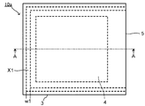
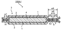
まず、図1に示す、工程(2)が工程(2b)のみで構成される場合の本発明の真空断熱材100A−Iの製造方法について説明する。図3A、図4A、図5Aは、それぞれ図1に示す製造方法の一例において、工程(1)終了後の芯材が収納された外被材(以下、「芯材収納外被材」ともいう。)、工程(2)終了後の芯材が収納され減圧溶着された外被材(以下、「真空断熱材前駆体」ともいう。)、および、工程(4I)終了後に得られた真空断熱材100A−Iの平面図を示す。図3B、図4B、図5Bは、それぞれ図3A、図4A、図5Aに平面図を示す部材の断面図である。
First, the manufacturing method of the vacuum
(I)の構成を有し、図1に模式的に示す製造方法により得られる真空断熱材は、図5A、図5Bに示す真空断熱材100A−Iである。真空断熱材100A−Iは、熱溶着層1と気密層2を有するフィルムを熱溶着層1同士が対向するように配置してなる外被材3と、外被材3の内部に収納された芯材4を有する。外被材3は、芯材4の外周よりも外側に位置し芯材4の周囲全体に亘り所定の幅で熱溶着層1同士が熱溶着された溶着部X1、X2を有する。
The vacuum heat insulating material having the configuration (I) and obtained by the manufacturing method schematically shown in FIG. 1 is a vacuum
なお、真空断熱材100A−Iにおいて、溶着部X1は芯材4を外被材3内に収納する前に形成された溶着部(収納前溶着部)であり、溶着部X2は芯材4を外被材3内に収納した後に形成された溶着部(収納後溶着部)である。溶着部X1と溶着部X2により芯材4の周囲全体を囲むように切れ間のない枠状の溶着部が形成され、芯材4を収納する外被材3の内部を減圧状態とすることを可能としている。以下、溶着部X1と溶着部X2からなる切れ間のない枠状の溶着部全体を溶着部Xともいう。
In addition, in vacuum
図5A、Bに示す真空断熱材100A−Iにおいては、外被材3は、主面が矩形のフィルム状であり、芯材4は主面が矩形の平板状であって、溶着部Xは内周および外周がそれぞれ矩形の枠状に形成されている。溶着部Xにおいて、枠の3辺が溶着部X1であり、残りの1辺が溶着部X2である。真空断熱材100A−Iにおいては、溶着部X2については、溶着部X2の外側に形成された保護溶着部Yを有する。保護溶着部Yは溶着部X1とともに芯材4の周囲全体を囲むように切れ間のない枠状に溶着された領域を形成する。このような構成とすることにより、芯材4を外被材3内に収納した後に形成された溶着部X2を外部雰囲気から遮断することが可能となる。結果として、得られる真空断熱材100A−Iは、真空度の低下が抑制された真空断熱材となる。
In the vacuum
本発明の製造方法においては、芯材4を外被材3内に収納した後に形成された溶着部X2に対しては、溶着部X2の外側に形成される保護溶着部Yを設けることが必須である。また、溶着部X1に対して保護溶着部Yを設けてもよい。その場合、保護溶着部のみで芯材の周囲全体を囲むように切れ間のない枠状に溶着された領域を形成する構成であってもよい。溶着部X1は芯材4を外被材3内に収納する前に形成された溶着部であり、溶着部にダストは挟持されていないため、溶着部X1に対して保護溶着部Yは必ずしも必要ではなく、製造工程に余分なプロセスを付加することになるため、コスト増の要因になるものの、より気密性が高くなるという利点はある。
In the manufacturing method of the present invention, it is indispensable to provide a protective weld portion Y formed outside the weld portion X2 for the weld portion X2 formed after the
ここで、真空断熱材100A−Iにおいて上記枠状の溶着部Xの別の構成としては、枠の2辺が溶着部X1であり、残りの2辺が溶着部X2である構成、枠の1辺が溶着部X1であり、残りの3辺が溶着部X2である構成、または全ての辺が溶着部X2である構成であってもよい。いずれの場合においても、溶着部Xのうち溶着部X2に対しては、溶着部X2の外側に保護溶着部Yを設ける。いずれの場合においても、保護溶着部Yは溶着部X1とともに、または保護溶着部Yのみで芯材4の周囲全体を囲むように切れ間のない枠状に溶着された領域を形成する。このようにして、本発明の方法により、芯材4を外被材3内に収納した後に形成された溶着部X2に対して、保護溶着部Yを設けることで、溶着部X2が芯材4等に起因するダストを挟み込んでいる場合であっても、長期使用において真空度の低下が抑制された真空断熱材を製造できる。
Here, in the vacuum
なお、真空断熱材100A−Iにおいて、溶着部X2と保護溶着部Yは、製造上、異なる工程で得られる溶着部であり、区別されるが、得られる真空断熱材100A−Iにおいては通常、識別できない。本明細書においては、溶着部X1のみからなる溶着部、溶着部X2と保護溶着部Yで形成される溶着部(溶着部X2と保護溶着部Yとの間の未溶着部を含む)、および溶着部X2と保護溶着部Yが合体した溶着部を併せて、「シール部」という。
Note that, in the vacuum
(工程(1))
図1において、(1)では、溶着部Xが部分的に未溶着である外被材3内に、芯材4を挿入して、外被材3内に芯材4を収納する工程(1)を示す。また、図3A、Bは、工程(1)終了後の芯材収納外被材10aを示す。本発明の製造方法においては、最終的に真空断熱材となったときに溶着部Xとなる部分が製造過程で未溶着である部分を未溶着部Mという。工程(1)においては、未溶着部Mを有する外被材3を用いる。
(Process (1))
In FIG. 1, in (1), the
図1の(1)、図3A、Bに示す外被材3は、熱溶着層1と気密層2が積層されてなる矩形で同じ大きさの2枚フィルムを、各フィルムが有する熱溶着層1を互いに対向させて重ね合わせた構成であり、3辺が予め所定の幅(w1)で熱溶着された袋状の外被材である。すなわち、最終的に4辺で構成される枠状の溶着部Xのうち3辺がすでに溶着部X1として形成され、残りの1辺が未溶着部Mであることで外被材3は未溶着部Mに対応する開口部5を有する袋形状を有する。
1 (A), FIG. 3 (A), and FIG. 3 (B), the
溶着部X1の幅(w1)は、真空断熱材として長期使用において真空度の低下を招かない幅であれば特に制限されない。熱溶着層1の構成材料や外被材3の大きさ等にもよるが、溶着部X1の幅(w1)は具体的には、5〜20mmが好ましく、5〜10mmがより好ましい。また、溶着部Xにおいて外周となる溶着部X1の外側の辺と外被材3の外周との距離は、真空断熱材として長期使用において真空度の低下を招かない距離であれば特に制限されず、熱溶着層1の構成材料や外被材3の大きさ等にもよるが、具体的には0〜15mm程度が好ましく、1〜10mm程度がより好ましい。
The width (w1) of the welded portion X1 is not particularly limited as long as it does not cause a decrease in the degree of vacuum during long-term use as a vacuum heat insulating material. The width (w1) of the welded portion X1 is specifically preferably 5 to 20 mm, and more preferably 5 to 10 mm, although it depends on the constituent material of the heat-welded
工程(1)では、このように袋状に成形された外被材3を準備し、開口部5から平板状に成形された芯材4をその内部に挿入する。図1に示される芯材4の主面は、溶着部Xの内側に収納可能な大きさであり、厚さは外被材3内部に収納可能な厚さである。このようにして、芯材収納外被材10aが得られる。芯材収納外被材10aの平面図および断面図を図3A、Bに示す。なお、芯材収納外被材10aの断面では、外被材3が有する対向する熱溶着層1同士の界面は、溶着部X1においては溶着により明確に存在するものではないが、図3Bでは、熱溶着層1同士の界面を熱溶着される前における界面として破線で示した。以下、断面図においては、溶着部の断面について上記と同様の記載とした。
In the step (1), the
本発明の製造方法に用いる外被材3および芯材4を構成する材料としては、以下に示す公知の材料が挙げられる。なお、工程(1)の方法は、従来、公知の方法である。工程(1)においては、外被材3、芯材4の種類によらず、芯材4がダストを発生する要因を含む場合、芯材4を外被材3に装填する際に、特に外被材3の開口部5で芯材4が外被材3と接触することでダストを発生し、例えば、図3Bに示すように該ダスト6が開口部5付近の熱溶着層1表面に付着すると考えられる。従来の方法においては、最終的に開口部を熱溶着する際にこのダストを挟み込んだ溶着部が形成され、このようなダストを挟持する溶着部に起因して真空度の低下が起こることがあった。本発明の製造方法においては、工程(1)以降に、工程(2)〜(4)を設けてダストを殆ど挟持しない保護溶着部を形成することで、ダストに起因する真空度低下を抑制したものである。
Examples of the material constituting the covering
なお、本明細書において「ダスト」とは、上記芯材から発生する芯材を構成する材料の一部等を含む微小体であって、それを挟持することで溶着部のリークを誘引し、真空断熱材の真空度に悪影響を及ぼすことが想定されるあらゆる微小体をいう。 In the present specification, “dust” is a microscopic object including a part of the material constituting the core material generated from the core material, and induces leakage of the welded portion by sandwiching it. It refers to all microscopic objects that are expected to have an adverse effect on the degree of vacuum of a vacuum heat insulating material.
このような本発明の製造方法による効果は、芯材として粉体を含む芯材を用いた場合にダストが発生し、付着しやすいことから、特に顕著である。本発明の真空断熱材の製造方法に用いる芯材としては、粉体と繊維体を含む圧縮成形体が好ましい。 Such an effect of the manufacturing method of the present invention is particularly remarkable because dust is easily generated and adhered when a core material containing powder is used as the core material. As a core material used for the manufacturing method of the vacuum heat insulating material of this invention, the compression molding body containing a powder and a fiber body is preferable.
<外被材>
本発明の製造方法において、外被材は、熱溶着層と気密層がフィルム状に積層された構成の外被材であればよく、通常、真空断熱材の外被材に使用される外被材が特に制限なく使用できる。外被材は、熱溶着層、気密層に加えて表面保護層を有していてもよく、表面保護層を有することが好ましい。この場合、外被材は、芯材を収納する側に熱溶着層を有し、中間層として気密層を有し、最外層として表面保護層を有する構成となる。
<Coating material>
In the manufacturing method of the present invention, the outer cover material may be an outer cover material having a structure in which a heat-welded layer and an airtight layer are laminated in a film shape, and is usually an outer cover material used as an outer cover material of a vacuum heat insulating material. The material can be used without any particular limitation. The jacket material may have a surface protective layer in addition to the heat-welded layer and the airtight layer, and preferably has a surface protective layer. In this case, the jacket material has a structure having a heat-welded layer on the side where the core material is accommodated, an airtight layer as an intermediate layer, and a surface protective layer as an outermost layer.
外被材の構成部材としては、例えば、気密層としての金属箔または金属蒸着層からなる金属層を表面保護層の片面上に有するラミネートフィルムを使用できる。また、金属箔を有するラミネートフィルムと金属蒸着層を有するラミネートフィルムの2種類のラミネートフィルムを組み合わせて使用してもよい。これらのラミネートフィルムの金属層側に熱溶着層が積層されて外被材が構成される。ここで、上記において符号2を気密層として説明しているが、各図面において符号2は気密層そのものであってもよく、気密層と表面保護層を有するラミネートフィルムであってもよい。
As a constituent member of the jacket material, for example, a laminate film having a metal layer made of a metal foil as an airtight layer or a metal vapor deposition layer on one surface of the surface protective layer can be used. Moreover, you may use combining two types of laminate films, the laminate film which has metal foil, and the laminate film which has a metal vapor deposition layer. A jacket material is formed by laminating a heat-welding layer on the metal layer side of these laminate films. Here, although the code |
外被材が有する熱溶着層、気密層、表面保護層を構成する材料としては、通常、真空断熱材の外被材に使用される上記各層を構成する材料と同様の材料が挙げられる。熱溶着層の構成材料として、具体的には、低密度ポリエチレン、鎖状低密度ポリエチレン、高密度ポリエチレン、ポリプロピレン、ポリアクリロニトリル、無延伸ポリエチレンテレフタレート、エチレン−ビニルアルコール共重合体、エチレン−テトラフルオロエチレン共重合体等が挙げられる。熱溶着層としては、これらの熱溶着層を構成する材料からなるフィルムや該フィルムを組み合わせた複合体からなってもよい。 Examples of the material constituting the heat-welded layer, the airtight layer, and the surface protective layer of the outer covering material include the same materials as those constituting the respective layers used for the outer covering material of the vacuum heat insulating material. Specifically, the constituent material of the heat welding layer is low density polyethylene, linear low density polyethylene, high density polyethylene, polypropylene, polyacrylonitrile, unstretched polyethylene terephthalate, ethylene-vinyl alcohol copolymer, ethylene-tetrafluoroethylene. A copolymer etc. are mentioned. As a heat welding layer, you may consist of the composite material which combined the film which consists of the material which comprises these heat welding layers, and this film.
気密層の構成材料として、具体的には、金属が挙げられる。表面保護層としては、ナイロンフィルム、ポリエチレンテレフタレートフィルム、ポリプロピレンフィルムの延伸加工品など、公知の材料が利用できる。 Specifically, a metal is mentioned as a constituent material of an airtight layer. As the surface protective layer, known materials such as nylon film, polyethylene terephthalate film, and stretched polypropylene film can be used.
<芯材>
芯材としては、真空断熱材に用いられる公知の芯材を使用できる。具体的には、気相比率90%前後の多孔体を材料として、これを板状に加工した芯材が挙げられる。工業的に利用できる多孔体として、通気性を有する発泡体、粉体、および繊維体等がある。芯材には、その使用用途や必要特性に応じて公知の断熱性の材料(以下、「断熱材材料」ともいう。)を適宜選択して使用することができる。
<Core>
As a core material, the well-known core material used for a vacuum heat insulating material can be used. Specifically, a core material obtained by processing a porous body having a gas phase ratio of about 90% into a plate shape is used. Examples of the porous body that can be industrially used include foams, powders, and fiber bodies having air permeability. For the core material, a known heat insulating material (hereinafter also referred to as “heat insulating material”) can be appropriately selected and used depending on the intended use and required characteristics.
このうち、発泡体としては、ウレタンフォーム、スチレンフォーム、フェノールフォーム等の連続気泡体が利用できる。真空封入時の真空引きが容易になる点から、芯材として利用する連続気泡体の通気量は1cm3/cm2sec以上が好ましい。また、粉体としては、無機系、有機系、およびこれらの混合物を利用できるが、工業的には、乾式シリカ、湿式シリカ、パーライト等を主成分とするものが使用できる。 Among these, as the foam, open-cell bodies such as urethane foam, styrene foam, and phenol foam can be used. In view of facilitating evacuation at the time of vacuum encapsulation, the air flow rate of the open cell body used as the core material is preferably 1 cm 3 / cm 2 sec or more. In addition, inorganic, organic, and mixtures thereof can be used as the powder, but industrially, powders mainly composed of dry silica, wet silica, pearlite, and the like can be used.
また、繊維体としては、無機系、有機系、およびこれらの混合物が利用できるが、コストと断熱性能の観点から無機繊維が有利である。無機繊維の一例としては、グラスウール、グラスファイバー、アルミナ繊維、シリカアルミナ繊維、シリカ繊維、ロックウール等、公知の材料を使用できる。 In addition, inorganic, organic, and mixtures thereof can be used as the fibrous body, but inorganic fibers are advantageous from the viewpoint of cost and heat insulation performance. As an example of the inorganic fiber, a known material such as glass wool, glass fiber, alumina fiber, silica alumina fiber, silica fiber, rock wool, or the like can be used.
さらに、これらの発泡体、粉体、および繊維体等の混合物や複合体も芯材に適用することができる。このような芯材として、具体的には、多孔質粉体と繊維体の複合体、例えば、エアロゲルブランケットが挙げられる。エアロゲルブランケットとしては、パイロジェル(アスペン社製)などが挙げられる。 Furthermore, mixtures and composites of these foams, powders, and fiber bodies can also be applied to the core material. Specific examples of such a core material include a composite of a porous powder and a fibrous body, for example, an airgel blanket. Examples of the airgel blanket include pyrogel (manufactured by Aspen).
これらのうち、粉体を含む断熱材材料が板状に圧縮成形された芯材について以下に説明する。粉体を含む芯材の断熱材材料としては、高強度な芯材を得やすい点から、粉体に加えて繊維が含まれていることが好ましい。また、繊維に加えてバインダを含んでいてもよいが、より良い断熱性能を得るためバインダの割合は少ないことが好ましく、含まないでもよい。 Of these, a core material in which a heat insulating material containing powder is compression-molded into a plate shape will be described below. As the heat insulating material of the core material including powder, it is preferable that fibers are included in addition to the powder from the viewpoint of easily obtaining a high-strength core material. In addition to the fibers, a binder may be included, but in order to obtain better heat insulating performance, the binder ratio is preferably small and may not be included.
≪粉体≫
以下に粉体を含む芯材の場合を例にとって説明する。
粉体としては、芯材に通常用いられる公知の粉体を使用できる。具体的には、ヒュームドシリカ、多孔質シリカ、輻射抑制材等が挙げられる。粉体としては、充分な強度を有する芯材が得られやすい点から、ヒュームドシリカを含むことが好ましい。
粉体は、1種のみを使用してもよく、2種以上を併用してもよい。
<< Powder >>
The case of a core material containing powder will be described below as an example.
As powder, the well-known powder normally used for a core material can be used. Specific examples include fumed silica, porous silica, and a radiation suppressing material. The powder preferably contains fumed silica from the viewpoint of easily obtaining a core material having sufficient strength.
Only one type of powder may be used, or two or more types may be used in combination.
ヒュームドシリカの具体例としては、例えば、アエロジル200(比表面積200m2/g、日本アエロジル社製)、アエロジル300(比表面積300m2/g、日本アエロジル社製)、CAB−O−SIL M−5(比表面積200m2/g、キャボット・スペシャルティ・ケミカルズ・インク社製)、CAB−O−SIL H−300(比表面積300m2/g、キャボット・スペシャルティ・ケミカルズ・インク社製)、レオロシールQS30(比表面積300m2/g、トクヤマ社製)等が挙げられる。
ヒュームドシリカは、1種のみを使用してもよく、2種以上を併用してもよい。
Specific examples of fumed silica include, for example, Aerosil 200 (specific surface area 200 m 2 / g, manufactured by Nippon Aerosil Co., Ltd.), Aerosil 300 (specific surface area 300 m 2 / g, manufactured by Nippon Aerosil Co., Ltd.), CAB-O-SIL M- 5 (specific surface area 200 m 2 / g, manufactured by Cabot Specialty Chemicals Inc.), CAB-O-SIL H-300 (specific surface area 300 m 2 / g, manufactured by Cabot Specialty Chemicals Inc.), Leoroseal QS30 ( And a specific surface area of 300 m 2 / g, manufactured by Tokuyama Corporation).
Fumed silica may use only 1 type and may use 2 or more types together.
多孔質シリカの具体例としては、例えば、M.S.GELやサンスフェア(いずれもAGCエスアイテック社製)等が挙げられる。 Specific examples of the porous silica include M.I. S. Examples include GEL and sunsphere (both manufactured by AGC S-Tech).
輻射抑制材としては、例えば、金属粒子(アルミニウム粒子、銀粒子、金粒子等)、無機粒子(グラファイト、カーボンブラック、炭化ケイ素、酸化チタン、酸化スズ、酸化鉄、チタン酸カリウム等)等が挙げられる。 Examples of the radiation suppressing material include metal particles (aluminum particles, silver particles, gold particles, etc.), inorganic particles (graphite, carbon black, silicon carbide, titanium oxide, tin oxide, iron oxide, potassium titanate, etc.). It is done.
バインダは、ケイ酸ナトリウム、リン酸アルミニウム、硫酸マグネシウム、塩化マグネシウム等の無機バインダを溶媒に溶解してバインダ液として用いることが好ましく、水溶液がより好ましい。 The binder is preferably used as a binder solution by dissolving an inorganic binder such as sodium silicate, aluminum phosphate, magnesium sulfate, or magnesium chloride in a solvent, and more preferably an aqueous solution.
≪繊維≫
断熱材材料に繊維が含まれると、高強度な芯材が得られやすい。
繊維としては、真空断熱材に通常使用される繊維が使用でき、例えば、樹脂繊維、無機繊維が挙げられる。なかでも、真空下でのアウトガスが少なく、真空度の低下による断熱性能の低下を抑制しやすい点、および耐熱性に優れる点から、無機繊維が好ましい。
≪Fiber≫
When fibers are included in the heat insulating material, a high-strength core material is easily obtained.
As a fiber, the fiber normally used for a vacuum heat insulating material can be used, For example, a resin fiber and an inorganic fiber are mentioned. Of these, inorganic fibers are preferred because they have less outgas in a vacuum, can easily suppress a decrease in heat insulation performance due to a decrease in the degree of vacuum, and are excellent in heat resistance.
無機繊維としては、例えば、アルミナ繊維、ムライト繊維、シリカ繊維、グラスウール、グラスファイバー、ロックウール、スラグウール、炭化ケイ素繊維、カーボン繊維、シリカアルミナ繊維、シリカアルミナマグネシア繊維、シリカアルミナジルコニア繊維、シリカマグネシアカルシア繊維等が挙げられる。 Examples of the inorganic fiber include alumina fiber, mullite fiber, silica fiber, glass wool, glass fiber, rock wool, slag wool, silicon carbide fiber, carbon fiber, silica alumina fiber, silica alumina magnesia fiber, silica alumina zirconia fiber, silica magnesia. Examples include calcia fiber.
≪粉体、バインダ、繊維の割合≫
粉体(100質量%)中のヒュームドシリカの割合は、50〜100質量%が好ましく、70〜100質量%がより好ましく、80〜100質量%が特に好ましい。ヒュームドシリカの割合が前記範囲の下限値以上であれば、強度の高い芯材が得られやすい。
≪Powder, binder, fiber ratio≫
The ratio of fumed silica in the powder (100% by mass) is preferably 50 to 100% by mass, more preferably 70 to 100% by mass, and particularly preferably 80 to 100% by mass. If the ratio of fumed silica is not less than the lower limit of the above range, a core material with high strength can be easily obtained.
粉体が輻射抑制材を含む場合、粉体(100質量%)中の輻射抑制材の割合は、3〜30質量%が好ましく、5〜25質量%がより好ましく、10〜20質量%が特に好ましい。 When the powder contains a radiation suppressing material, the proportion of the radiation suppressing material in the powder (100% by mass) is preferably 3 to 30% by mass, more preferably 5 to 25% by mass, and particularly 10 to 20% by mass. preferable.
繊維の割合は、粉体100質量部に対する添加量として、1〜30質量部が好ましく、2〜20質量部がより好ましく、4〜10質量部が特に好ましい。繊維の割合が前記範囲の下限値以上であれば、高強度な芯材が得られやすい。繊維の割合が前記範囲の上限値以下であれば、繊維による固体伝熱の増大を抑制できるため、断熱性能の低下を抑制しやすい。 The ratio of the fiber is preferably 1 to 30 parts by mass, more preferably 2 to 20 parts by mass, and particularly preferably 4 to 10 parts by mass with respect to 100 parts by mass of the powder. When the fiber ratio is equal to or higher than the lower limit of the above range, a high-strength core material is easily obtained. If the ratio of the fiber is equal to or less than the upper limit of the above range, an increase in solid heat transfer due to the fiber can be suppressed, so that it is easy to suppress a decrease in heat insulation performance.
芯材として粉体を用いる場合の、粉体の好ましい組成は質量比で、ヒュームドシリカ:多孔質シリカ:輻射抑制材として、70〜90:0〜20:10〜20が好ましい。また粉体が繊維を含む場合の好ましい組成は質量比でヒュームドシリカ:多孔質シリカ:繊維:輻射抑制材として、70〜90:0〜20:5〜10:5〜20が好ましい。 When powder is used as the core material, the preferred composition of the powder is mass ratio, and 70 to 90: 0 to 20:10 to 20 is preferred as fumed silica: porous silica: radiation suppression material. Moreover, 70-90: 0-20: 5-10: 5-20 are preferable as a preferable composition when a powder contains a fiber as a fumed silica: porous silica: fiber: radiation suppression material by mass ratio.
(工程(2))
上記のとおり、図1に示す真空断熱材100A−Iの製造方法においては、工程(2)は、芯材4を収納した外被材3である芯材収納外被材10aについて、未溶着部Mの全部が溶着された状態となるように減圧下で熱溶着層1同士を熱溶着する工程(2b)、すなわち減圧溶着工程のみからなる。工程(2)終了後に得られた真空断熱材前駆体について、図1においては、上記減圧下熱溶着後に大気圧条件に戻された状態として、10bの符号を付して示す。また、図4A、Bに、真空断熱材前駆体10bの平面図と断面図を示す。なお、工程(2)において任意の工程である工程(2a)すなわち常圧溶着工程については、図2に示す真空断熱材100Bの製造方法において説明する。
(Process (2))
As described above, in the method for manufacturing the vacuum
図1では、(2b)において、(1)で準備した芯材収納外被材10aを減圧条件下に置き、外被材3の未溶着部Mの全部が溶着された状態となるように熱溶着を行う。具体的には、最終的に4辺で構成される枠状の溶着部Xのうちすでに溶着部X1として形成された3辺を除く残りの1辺が溶着された状態となるように、その部分の対向する熱溶着層1同士を熱溶着して、真空断熱材前駆体10bを得る。すなわち、真空断熱材前駆体10bは、枠状の溶着部Xが全て溶着され、その内側に芯材4が位置するように減圧封入された構成を有する。なお、工程(2b)で熱溶着されて得られる溶着部は、芯材4を外被材3内に収納した後に形成された溶着部(収納後溶着部)X2である。
In FIG. 1, in (2b), the core
また、溶着部X1の1辺として1枚の外被材10aを折り曲げた折り曲げ部を代用してもよい。なお、工程(2b)において、未溶着部Mの外側をクリップ等で仮止めすると、真空にした時に外被材のずれを防止できるため好ましい。
Moreover, you may substitute the bending part which bent one sheet |
真空断熱材前駆体10bにおける溶着部X2の幅(w2)は、溶着部X2の形成により外被材の内部が減圧状態を維持できる幅であり、後で溶着部X2のシール機能を補助するように形成される保護溶着部Yとともに真空断熱材として長期使用において真空度の低下を招かない幅であれば特に制限されない。上記溶着部X1の幅(w1)と同様であってもよく、異なってもよい。保護溶着部Yの構成等にもよるが、溶着部X2の幅(w2)は具体的には、5〜20mmが好ましい。
The width (w2) of the welded portion X2 in the vacuum heat insulating
また、工程(2b)において、溶着部X2を形成するための熱溶着は芯材4が収納された外被材3の外縁から内側に向かって所定の幅(w3)を有する端部7を残して行われる。端部7の幅(w3)は、溶着部Xにおいて外周となる溶着部X2の外側の辺と外被材3の外縁との距離であり、次に行われる工程(3)の後の工程(4)において、保護溶着部Yが形成可能な幅であれば特に制限されない。後述する保護溶着部Yの幅(w4)および真空断熱材100A−Iにおいては溶着部X2と保護溶着部Yとの間の未溶着部の幅(w8)、真空断熱材100A−IIにおいては溶着部X2と保護溶着部Yの重なり幅(w5)等に合わせて適宜調整される。端部7の幅(w3)は、好ましくは、保護溶着部Yの外側の辺から外被材3の外縁までの距離が0〜15mm程度となるように調整される。
Further, in the step (2b), the thermal welding for forming the welded portion X2 leaves the
工程(2b)を実行するための装置としては、板状の芯材を袋状の外被材に挿入して製造される真空断熱材において、通常使用される装置を、特に制限なく使用できる。例えば、ヒートシール機能付きの真空チャンバー等が挙げられる。また、製造時の減圧条件および熱溶着の条件についても、通常、このような装置を用いて上記のような真空断熱材を製造する場合と同様の条件を適用できる。 As an apparatus for executing the step (2b), a normally used apparatus can be used without particular limitation in a vacuum heat insulating material manufactured by inserting a plate-shaped core material into a bag-shaped outer cover material. For example, a vacuum chamber with a heat seal function may be used. In addition, the same conditions as in the case of producing the vacuum heat insulating material as described above using such an apparatus can be applied to the decompression conditions and the heat welding conditions during the production.
なお、真空断熱材100A−Iにおいて、外被材3の溶着部Xの内側における外被材3内部の真空度は、優れた断熱性能が得られ、また真空断熱材の寿命が長くなる点から、1×10³Pa以下が好ましく、1×10²Pa以下がより好ましい。
In addition, in the vacuum
減圧溶着工程における製造条件は、好ましくは上記真空度が達成できる条件に設定される。また、外被材3が有する熱溶着層を構成する材料は上記のとおりであり、上記熱溶着の際には該材料に合わせて好適な溶着温度を設定する。さらに、通常1〜5kg/cm2程度の加圧条件下で熱溶着が行われる。
The manufacturing conditions in the reduced pressure welding step are preferably set to conditions that allow the vacuum degree to be achieved. Moreover, the material which comprises the heat welding layer which the
ここで、図1に示す工程(1)、(2b)を経て得られる、真空断熱材前駆体10bにおいては、芯材の収納後に熱溶着された収納後溶着部である溶着部X2が、上記工程(1)で芯材4から主として発生し開口部5付近の熱溶着層1表面に付着したダスト6をそのまま挟み込んだ状態で形成されている。従来の製造方法においては、このような状態の真空断熱材前駆体10bをそのまま真空断熱材の完成品としたことで、溶着部X2からのリークにより真空度が経時的に低下する速度が早くなるリスクがある。本発明においては、さらに以下の工程(3)、工程(4I)、好ましくは工程(4II)により、溶着部X2のシール性を補うように、その外側に、好ましくは溶着部X2の外側の辺を覆うように保護溶着部Yを形成し長期使用における真空度の低下速度が速まるリスクを抑制したものである。
Here, in the vacuum heat insulating
なお、溶着部X2が挟み込むダスト量を低減させるために、工程(1)と工程(2)の間に、すなわち、外被材3に芯材4を収納後、収納後溶着部である溶着部X2を形成する前に、溶着部X2となる未溶着部の熱溶着層1表面に付着したダスト6を除去する、例えば、以下のクリーニング工程と同様の工程を設けてもよい。しかしながら、工程(2b)における減圧の操作によりダスト6が移動し、結果として相当量のダスト6が溶着部X2に挟持されるため、溶着部X2が挟み込むダスト量を低減させる効果は小さく、効率の点で不利となる場合もある。
In addition, in order to reduce the amount of dust sandwiched by the welded portion X2, the welded portion which is the welded portion after storing after the
(工程(3))
工程(3)は、工程(2)で得られる真空断熱材前駆体10bについて、芯材の収納後に熱溶着された収納後溶着部である溶着部X2の外側に残された外被材3の端部7において対向する熱溶着層1の表面をクリーニングする工程である。図1の(3)および、図4Bは該クリーニング工程を模式的に示す図である。
(Process (3))
In the step (3), for the vacuum heat insulating
上記で説明したとおり、工程(2)で得られる真空断熱材前駆体10bは、外被材3が溶着部X2の外側に幅(w3)の端部7を有する。図1の(3)、図4Bに示すとおり、外被材3の端部7においては、熱溶着層1と気密層2を有する2枚のフィルムが熱溶着層1同士が対向するように配置された状態、すなわち熱溶着がなされていない状態である。また、図4Bに示すとおり、工程(2)の後の端部7において、互いに対向する熱溶着層1の表面には、工程(1)において芯材4から主として発生し該表面に付着したダスト6が残留している。
As described above, in the vacuum heat insulating
工程(3)はこのような端部7の熱溶着層1表面をクリーニングすることで、該表面に残留したダスト6を除去する。熱溶着層1の表面をクリーニングする方法、すなわち熱溶着層1の表面に残留したダスト6を除去する方法としては、通常、樹脂フィルムなどに付着した粉末等のダストを取り除くために用いられる様々な方法が適用できる。
In the step (3), the
クリーニングの方法として具体的には、紙や布を用いたダストの拭き取り、粘着テープなど粘着性のある素材にダストを付着させる、エアの吹き込みによりダストを吹き飛ばす、掃除機によるダストの吸引などが挙げられる。なかでも、熱溶着層に傷を付けることなくダストを取り除く観点から、紙や布を用いたダストの拭き取りが好ましい。用いる紙や布としてはそれ自体ダストを発生しないものが好ましい。具体的には、ウエットティッシュ等の湿った紙や布を用いて拭き取る方法が簡便で効果的にダストを取り除くことができるため特に好ましい。紙や布としては、レイヨンやポリエステル等の合成繊維をシート状にした不織布が好ましい。 Specific cleaning methods include wiping dust with paper and cloth, attaching dust to adhesive materials such as adhesive tape, blowing dust by blowing air, and sucking dust with a vacuum cleaner. It is done. Among these, from the viewpoint of removing dust without scratching the heat-welded layer, wiping off dust using paper or cloth is preferable. The paper or cloth used is preferably one that does not generate dust itself. Specifically, a method of wiping with wet paper or cloth such as wet tissue is particularly preferable because dust can be removed easily and effectively. As the paper or cloth, a nonwoven fabric in which synthetic fibers such as rayon and polyester are formed into a sheet shape is preferable.
なお、クリーニング工程において、湿った紙や布を用いて拭き取る方法をとった場合、工程(4)の前に、熱溶着層1の表面を十分に乾燥させることが好ましい。
In the cleaning step, when a method of wiping with wet paper or cloth is used, it is preferable to sufficiently dry the surface of the heat-welded
(工程(4I))
工程(4I)は、工程(3)に次いで行われる保護溶着部Yを形成する工程である。図1においては、(4)として工程(4I)をとる場合の工程(4I)後に得られた真空断熱材100A−Iを真空断熱材100A−IIとともに右下に示す。図5A、Bは真空断熱材100A−Iの平面図および断面図である。
(Process (4I))
Step (4I) is a step of forming protective weld Y that is performed subsequent to step (3). In FIG. 1, the vacuum
工程(4I)において、保護溶着部Yは、芯材の収納後に熱溶着された収納後溶着部である溶着部X2の外側に、工程(3)でクリーニングされた熱溶着層1同士が熱溶着された領域を有するような幅(w4)で形成される。保護溶着部Yは、収納前溶着部である溶着部X1とともに芯材の周囲全体に亘り熱溶着された領域を形成する。
In the step (4I), the protective welding portion Y is formed by thermally welding the heat-welded
保護溶着部Yは、溶着部X2の外側に溶着部X2と平行し、かつ溶着部X2の外側の辺と保護溶着部Yの内側の辺が所定の距離(w8)を有するように幅(w4)で形成される。溶着部X2の外側の辺より外側の領域は工程(3)でクリーニングされているため、保護溶着部Yにおける熱溶着層1同士が熱溶着された領域は該クリーニングされた領域内にある。
The protective weld Y is parallel to the weld X2 on the outside of the weld X2, and the width (w4) is such that the outer side of the weld X2 and the inner side of the protective weld Y have a predetermined distance (w8). ). Since the region outside the outer side of the welded portion X2 is cleaned in the step (3), the region where the heat-welded
保護溶着部Yの幅(w4)は、シール効果を高く維持する観点から、3〜15mmが好ましく、5〜10mmがより好ましい。 The width (w4) of the protective welded portion Y is preferably 3 to 15 mm, and more preferably 5 to 10 mm from the viewpoint of maintaining a high sealing effect.
上記のとおり、溶着部X2と該溶着部X2の外側に形成された保護溶着部Y(溶着部X2と保護溶着部Yとの間の未溶着部を含む)とを合わせてシール部Sが構成される。シール部Sの幅(w9)は、w2+w4+w8で示される。w8は溶着部X2と保護溶着部Yとの間の未溶着部の幅である。w8は0〜5mmが好ましい。シール部の外側の辺、すなわち保護溶着部Yの外側の辺から外被材の外周までの距離は、0〜15mmが好ましく、1〜10mmがより好ましい。 As described above, the seal portion S is configured by combining the weld portion X2 and the protective weld portion Y (including the unwelded portion between the weld portion X2 and the protective weld portion Y) formed outside the weld portion X2. Is done. The width (w9) of the seal portion S is indicated by w2 + w4 + w8. w8 is the width of the unwelded portion between the welded portion X2 and the protective welded portion Y. w8 is preferably 0 to 5 mm. The distance from the outer side of the seal portion, that is, the outer side of the protective welding portion Y, to the outer periphery of the jacket material is preferably 0 to 15 mm, and more preferably 1 to 10 mm.
なお、保護溶着部Yを形成する際の熱溶着の条件については、通常、上記のような外被材が有する熱溶着層同士を熱溶着する場合と同様の条件を適用できる。また、外被材が有する熱溶着層を構成する材料は上記のとおりであり、上記熱溶着の際には該材料に合わせて好適な溶着温度を設定する。さらに、通常1〜5kg/cm2程度の加圧条件下で熱溶着が行われる。ここで、本明細書において、特に断りのない限り、減圧下で行う熱溶着以外の熱溶着は、常圧の環境で行われるものである。 In addition, about the conditions of the heat welding at the time of forming the protective welding part Y, the conditions similar to the case where the heat welding layers which the above-mentioned jacket materials have are heat-welded normally are applicable. Moreover, the material which comprises the heat welding layer which a jacket material has is as above, and in the case of the said heat welding, suitable welding temperature is set according to this material. Furthermore, heat welding is usually performed under a pressurized condition of about 1 to 5 kg / cm 2 . Here, in this specification, unless otherwise specified, thermal welding other than thermal welding performed under reduced pressure is performed in an environment of normal pressure.
このようにして得られる真空断熱材100A−Iにおいては、保護溶着部Yと溶着部X2からなるシール部Sにおいて、溶着層X2に挟持されるダスト6の量は相応の量がある。これに対して保護溶着部Yは工程(3)でクリーニングされた領域で熱溶着層1同士が熱溶着されて形成されているので、保護溶着部Yに挟持されるダスト量は非常に少ない。また、所定の幅(w8)を有する溶着部X2と保護溶着部Yとの間の未溶着部においても挟持するダストの量が少ない。
In the vacuum
また、真空断熱材100A−Iにおいて、芯材収納前に形成された溶着部X1、芯材収納後に形成された溶着部X2、および保護溶着部Yからなる枠状に形成されたシール部のうち、溶着部X1については、挟持されるダストは略存在しないと言える。本発明の製造方法においては、このようにして、従来の真空断熱材の製造方法に、簡便な工程(3)、(4I)を加えることによって、長期使用において真空度の低下が抑制された真空断熱材を容易にかつ経済的に製造できる。本発明の製造方法は特に芯材となる多孔体がダストを発生する要因である粉体を含む場合に好ましく使用できる。
Further, in the vacuum
次に、図2に示す、工程(2)が工程(2a)および工程(2b)で構成される場合の本発明の真空断熱材100B−Iの製造方法について説明する。 Next, the manufacturing method of the vacuum heat insulating material 100B-I of this invention in case the process (2) shown in FIG. 2 is comprised by the process (2a) and the process (2b) is demonstrated.
真空断熱材100B−Iにおいて、溶着部X1は芯材4を外被材3内に収納する前に形成された溶着部(収納前溶着部)であり、溶着部X2は芯材4を外被材3内に収納した後に形成された溶着部(収納後溶着部)である。図2に示す製造方法においては、溶着部X2は、工程(2a)と工程(2b)により形成される。溶着部X1と溶着部X2により芯材4の周囲全体を囲むように切れ間のない枠状の溶着部が形成され、芯材4を収納する外被材3の内部を減圧状態とすることを可能としている。
In the vacuum heat insulating material 100B-I, the welded portion X1 is a welded portion (a welded portion before storage) formed before the
図2に示す製造方法では、工程(1)で準備する未溶着部を有する外被材3は、図1に示す製造方法で示す未溶着部を有する外被材3と、未溶着部の領域が異なる以外は、全て同様である。
In the manufacturing method shown in FIG. 2, the
具体的には、図2の(1)に示す外被材3は、熱溶着層1と気密層2が積層されてなる矩形で同じ大きさの2枚フィルムを、各フィルムが有する熱溶着層1を互いに対向させて重ね合わせた構成であり、隣り合う2辺が予め所定の幅(w1)で熱溶着された外被材である。すなわち、最終的に4辺で構成される枠状の溶着部Xのうち隣り合う2辺がすでに溶着部X1として形成され、残りの隣り合う2辺が未溶着部Mであることで外被材3は未溶着部Mに対応する開口部5を有する形状である。
Specifically, the
工程(1)では、このように成形された外被材3を準備し、開口部5から平板状に成形された芯材4をその内部に挿入する。図2に示される芯材4の主面は、溶着部Xの内周より内側に外周が位置する大きさであり、厚さは外被材3内部に収納可能な厚さである。
In the step (1), the
工程(1)において外被材3の開口部5の形状を図2に示すように図1に示す場合に比べて大きくした場合であっても、芯材4を外被材3に装填する際に、特に外被材3の開口部5で芯材4が外被材3と接触することでダストを発生し、該ダスト6が開口部5付近の熱溶着層1表面に付着することに変わりはない。よって、工程(2)の収納後溶着工程を行い、次いで、工程(3)のクリーニング工程および工程(4I)の保護溶着工程を行う本発明の製造方法が、長期使用においても真空度の低下が抑制された真空断熱材を得る上で効果を発揮する。
Even when the shape of the opening 5 of the
図2に示す製造方法においては、工程(1)で得られる芯材収納外被材について、工程(2b)の減圧溶着に先だって工程(2a)により未溶着部の1辺を熱溶着する。そして、3辺が熱溶着された外被材の残りの1辺を工程(2b)により減圧溶着する。工程(2a)により熱溶着して得られる溶着部X2は、芯材4を外被材3内に収納した後に形成された溶着部(収納後溶着部)である。なお、工程(2a)による熱溶着の具体的な方法は、上に説明した保護溶着部Yを形成する際の熱溶着の方法と同様にできる。
In the manufacturing method shown in FIG. 2, one side of the unwelded portion is thermally welded in the step (2a) prior to the vacuum welding in the step (2b) for the core material housing material obtained in the step (1). Then, the remaining one side of the jacket material on which the three sides are heat-welded is vacuum-welded in the step (2b). The welded part X2 obtained by heat welding in the step (2a) is a welded part (post-contained welded part) formed after the
工程(2a)により熱溶着して得られる溶着部X2の幅および形成位置については、図1に示す製造方法において、工程(2b)において溶着部X2を形成する際の幅および形成位置と同様にできる。すなわち、溶着部X2の幅は5〜20mmが好ましく、溶着部X2の形成は、外被材3の外縁から内側に向かって所定の幅(w3)を有する端部7を残して行われる。
About the width | variety and formation position of the welding part X2 obtained by heat welding by a process (2a), in the manufacturing method shown in FIG. 1, it is the same as the width | variety and formation position at the time of forming the welding part X2 in a process (2b). it can. That is, the width of the welded portion X2 is preferably 5 to 20 mm, and the welded portion X2 is formed while leaving the
図2に示す製造方法においては、次いで、上記図1に示す工程2(b)と同様の減圧下での溶着工程である工程(2b)を行う。このようにして、図2に示す工程(1)、(2a)、(2b)を経て得られる、真空断熱材前駆体10bにおいては、芯材の収納後に熱溶着された収納後溶着部である2辺の溶着部X2が、上記工程(1)で芯材4から主として発生し開口部5付近の熱溶着層1表面に付着したダスト6をそのまま挟み込んだ状態で形成されている。また、2辺の溶着部X2の外側に残された外被材3の端部7において対向する熱溶着層1の表面にはダスト6が残存している。
In the manufacturing method shown in FIG. 2, next, step (2b) which is a welding step under reduced pressure similar to step 2 (b) shown in FIG. 1 is performed. In this way, the vacuum heat insulating
したがって、工程(3)においては、2辺の溶着部X2の外側に残された外被材3の端部7について上記同様にクリーニングを行い、さらに工程(4I)により、上記と同様にして2辺の溶着部X2の両方について、保護溶着部Yを、溶着部X2の外側に、溶着部X2の外側の辺と保護溶着部Yの内側の辺が所定の距離(w8)を有するように、工程(3)でクリーニングされた熱溶着層1同士が熱溶着された領域を有するような幅(w4)で形成する。保護溶着部Yは溶着部X1とともに、または保護溶着部Yのみで芯材4の周囲全体を囲むように切れ間のない枠状に溶着された領域を形成する。
Therefore, in the step (3), the
このように本発明の製造方法においては、図2に示す方法をとった場合においても、従来の真空断熱材の製造方法に、簡便な工程(3)、(4I)を加えることによって、真空断熱材100A−Iと同様に長期使用において真空度の低下が抑制された真空断熱材100B−Iを容易にかつ経済的に製造できる。
As described above, in the manufacturing method of the present invention, even when the method shown in FIG. 2 is adopted, by adding simple steps (3) and (4I) to the conventional vacuum heat insulating material manufacturing method, Similarly to the
次に(I)の構成の真空断熱材において、好ましい構成である(II)の構成の真空断熱材の製造方法を説明する。 Next, the manufacturing method of the vacuum heat insulating material of the structure of (II) which is a preferable structure in the vacuum heat insulating material of the structure of (I) is demonstrated.
本発明の製造方法の好ましい構成である(II)に係る真空断熱材は、熱溶着層と気密層を有するフィルムを前記熱溶着層同士が対向するように配置してなる外被材と、前記外被材の内部に収納された芯材を有する真空断熱材であり、前記外被材は前記芯材の周囲全体に亘り所定の幅で前記熱溶着層同士が熱溶着された溶着部および前記溶着部の少なくとも一部に部分的に重なるように前記溶着部の外側に形成された保護溶着部を有するとともに、内部が減圧状態である。 The vacuum heat insulating material according to (II), which is a preferred configuration of the production method of the present invention, is a jacket material formed by arranging a film having a heat welding layer and an airtight layer so that the heat welding layers face each other, It is a vacuum heat insulating material having a core material housed inside a jacket material, and the jacket material is a welded portion in which the heat-welded layers are heat-welded with a predetermined width over the entire periphery of the core material and While having the protective welding part formed in the outer side of the said welding part so that it may partially overlap with at least one part of a welding part, the inside is a pressure reduction state.
本発明の(II)の構成の真空断熱材の製造方法は、上記した(II)の構成の真空断熱材を製造する方法であって、以下の(1)〜(4II)の工程を備える。
(1)前記溶着部において前記溶着部となる部分が未溶着である未溶着部を有する前記外被材の内部に前記芯材を収納する工程(以下、工程(1)または「収納工程」という。)
(2)前記芯材を収納した前記外被材について、前記未溶着部の前記熱溶着層同士を減圧に必要な一部を残して予め熱溶着した後、または熱溶着せずに、前記未溶着部の全部が溶着された状態となるように減圧下で前記熱溶着層同士を熱溶着する工程であり、前記いずれの熱溶着についても前記芯材が収納された外被材の外縁から所定の幅の端部を残して行う工程(以下、工程(2)または「収納後溶着工程」という。)
(3)前記芯材の収納後に熱溶着された収納後溶着部の外側に残された前記外被材の端部において前記対向する熱溶着層の表面をクリーニングする工程(以下、工程(3)または「クリーニング工程」という。)
(4II)前記保護溶着部を、前記収納後溶着部の外側の辺から内側に所定の重なり幅を有するとともに前記クリーニングされた熱溶着層同士が熱溶着された領域を有するように形成する工程(以下、工程(4II)または「保護溶着工程II」という。)
The manufacturing method of the vacuum heat insulating material of the structure of (II) of this invention is a method of manufacturing the above-mentioned vacuum heat insulating material of the structure of (II), Comprising: The process of the following (1)-(4II) is provided.
(1) A step (hereinafter referred to as a step (1) or “housing step”) in which the core material is housed in the outer cover material having an unwelded portion where the welded portion of the welded portion is unwelded. .)
(2) About the jacket material containing the core material, the heat-welded layers of the unwelded portions are heat-welded in advance leaving a part necessary for decompression, or without heat-welding, It is a step of heat-welding the heat-welded layers under reduced pressure so that all of the welded parts are in a welded state, and for any of the heat-welding, a predetermined distance from the outer edge of the jacket material in which the core material is stored The process performed leaving the edge part of the width | variety (henceforth a process (2) or "welding process after accommodation").
(3) A step of cleaning the surface of the facing heat-welded layer at the end portion of the outer cover material remaining outside the post-storage welded portion that has been heat-welded after the core material has been stored (hereinafter, step (3) Or referred to as “cleaning process”.)
(4II) A step of forming the protective welded portion so as to have a predetermined overlapping width inward from the outer side of the post-storage welded portion and a region where the cleaned heat-welded layers are thermally welded ( Hereinafter, referred to as step (4II) or “protective welding step II”.)
以下、本発明の(II)の構成の真空断熱材の製造方法における各工程を説明する。なお、(I)の構成を有する真空断熱材の製造方法と同じ図を用いた説明においては、説明が重複する場合は説明を省略する。図1、図2は、本発明の製造方法の例をそれぞれ模式的に示す図である。 Hereinafter, each process in the manufacturing method of the vacuum heat insulating material of the structure of (II) of this invention is demonstrated. In addition, in description using the same figure as the manufacturing method of the vacuum heat insulating material which has the structure of (I), description is abbreviate | omitted when description overlaps. 1 and 2 are diagrams schematically showing examples of the production method of the present invention.
図1において工程(1)、(2b)、(3)は(I)の構成を有する真空断熱材100A−Iの製造方法と同様である。(II)の構成の真空断熱材における(4II)工程は、図1においては、(I)の構成の真空断熱材における(4I)工程とともに右下に示される。
In FIG. 1, steps (1), (2b), and (3) are the same as the manufacturing method of the vacuum
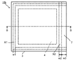
図6Aは、工程(4II)終了後に得られた真空断熱材100A−IIの平面図を示す。図6Bは、図6Aに平面図を示す部材の断面図である。
FIG. 6A shows a plan view of the vacuum
(II)の構成を有し、図1に模式的に示す製造方法により得られる真空断熱材は、図6A、図6Bに示す真空断熱材100A−IIである。真空断熱材100A−IIは、熱溶着層1と気密層2を有するフィルムを熱溶着層1同士が対向するように配置してなる外被材3と、外被材3の内部に収納された芯材4を有する。外被材3は、芯材4の外周よりも外側に位置し芯材4の周囲全体に亘り所定の幅で熱溶着層1同士が熱溶着された溶着部X1、X2を有する。
The vacuum heat insulating material having the configuration of (II) and obtained by the manufacturing method schematically shown in FIG. 1 is a vacuum
なお、真空断熱材100A−IIにおいて、溶着部X1は芯材4を外被材3内に収納する前に形成された溶着部(収納前溶着部)であり、溶着部X2は芯材4を外被材3内に収納した後に形成された溶着部(収納後溶着部)である。溶着部X1と溶着部X2により芯材4の周囲全体を囲むように切れ間のない枠状の溶着部が形成され、芯材4を収納する外被材3の内部を減圧状態とすることを可能としている。以下、溶着部X1と溶着部X2からなる切れ間のない枠状の溶着部全体を溶着部Xともいう。
In addition, in vacuum
図6A、Bに示す真空断熱材100A−IIにおいては、外被材3は、主面が矩形のフィルム状であり、芯材4は主面が矩形の平板状であって、溶着部Xは内周および外周がそれぞれ矩形の枠状に形成されている。溶着部Xにおいて、枠の3辺が溶着部X1であり、残りの1辺が溶着部X2である。真空断熱材100A−IIにおいては、溶着部X2については、溶着部X2と部分的に重なるように、具体的には、溶着部X2の外側の辺から内側に向かって所定の幅が重なるように、溶着部X2の外側に形成された保護溶着部Yを有する。
In the vacuum
上記のようにして保護溶着部Yを形成することで、保護溶着部Yは溶着部X1とともに芯材4の周囲全体を囲むように切れ間のない枠状に溶着された領域を形成する。このような構成とすることにより、芯材4を外被材3内に収納した後に形成された溶着部X2を外部雰囲気から遮断することが可能となる。結果として、得られる真空断熱材100A−IIは、真空度の低下が抑制された真空断熱材となる。
By forming the protective welded portion Y as described above, the protective welded portion Y forms a region that is welded in a continuous frame shape so as to surround the entire periphery of the
(II)の構成を有する真空断熱材の製造方法においては、芯材4を外被材3内に収納した後に形成された溶着部X2に対しては、溶着部X2の外側の辺を覆うようにして溶着部X2と部分的に重なるように形成される保護溶着部Yを設けることが必須である。溶着部X1に対して保護溶着部Yを設けてもよいが、溶着部X1は芯材4を外被材3内に収納する前に形成された溶着部であり、溶着部にダストは挟持されていないため、必ずしも必要ではなく、製造工程に余分なプロセスを付加することになるため、コスト増の要因になる。
In the method for manufacturing a vacuum heat insulating material having the configuration (II), the outer side of the welded portion X2 is covered with respect to the welded portion X2 formed after the
ここで、真空断熱材100A−IIにおいて上記枠状の溶着部Xの別の構成としては、枠の2辺が溶着部X1であり、残りの2辺が溶着部X2である構成、枠の1辺が溶着部X1であり、残りの3辺が溶着部X2である構成、または全ての辺が溶着部X2である構成であってもよい。いずれの場合においても、溶着部Xのうち溶着部X2に対しては、溶着部X2の外側に溶着部X2の外側の辺を覆うようにして溶着部X2と部分的に重なるように保護溶着部Yを設ける。
Here, in the vacuum
本発明の方法により、芯材4を外被材3内に収納した後に形成された溶着部X2に対して、その外側に所定の幅の重なり部分を有するように保護溶着部Yを設けることで、溶着部X2が芯材4等に起因するダストを挟み込んでいる場合であっても、長期使用において真空度の低下が抑制された真空断熱材を製造できる。前記重なり部分を設けると、溶着部X2と保護溶着部Yとの間に重なりがないか溶着部X2と保護溶着部Yとの間に未溶着部がある場合よりも長期使用において真空度の低下が抑制されやすい。溶着部X2が保護溶着部Yより先に劣化すると、前記未溶着部に残存した空気により真空度が低下するためと考えられる。
By providing the welded portion X2 formed after the
(工程(1))
工程(1)は、真空断熱材A100−Iと好ましい態様も含め同様である。
(Process (1))
Step (1) is the same as the vacuum heat insulating material A100-I, including the preferred embodiment.
<外被材>
真空断熱材A100−IIの製造方法において、外被材は好ましい態様も含め真空断熱材A100−Iと同様である。
<Coating material>
In the manufacturing method of the vacuum heat insulating material A100-II, the jacket material is the same as that of the vacuum heat insulating material A100-I including the preferred embodiment.
<芯材>
真空断熱材A100−IIの製造方法において、芯材は好ましい態様も含め真空断熱材A100−Iと同様である。
<Core>
In the manufacturing method of the vacuum heat insulating material A100-II, the core material is the same as that of the vacuum heat insulating material A100-I including the preferred embodiment.
(工程(2))
真空断熱材A100−IIの製造方法において、工程(2)は好ましい態様も含め真空断熱材A100−Iと同様である。
(Process (2))
In the manufacturing method of the vacuum heat insulating material A100-II, the step (2) is the same as the vacuum heat insulating material A100-I including the preferred embodiment.
(工程(3))
真空断熱材A100−IIの製造方法において、工程(3)は好ましい態様も含め真空断熱材A100−Iと同様である。
(Process (3))
In the manufacturing method of the vacuum heat insulating material A100-II, the step (3) is the same as the vacuum heat insulating material A100-I including the preferred embodiment.
(工程(4II))
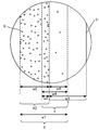
工程(4II)は、工程(3)に次いで行われる保護溶着部Yを形成する工程である。図1においては、(4)として工程(4II)をとる場合の工程(4II)後に得られた真空断熱材100A−IIを真空断熱材100A−Iとともに右下に示す。図6A、Bは真空断熱材100A−IIの平面図および断面図であり、図7は真空断熱材100A−IIの収納後溶着部X2と保護溶着部Yの拡大平面図である。これらにより溶着部X2と保護溶着部Yの形成領域の関係について説明する。なお、図7に示すダスト6は、真空断熱材100A−IIの表面に存在するものではなく、対向する熱溶着層同士が熱溶着した界面に存在するものを模式的に示している。
(Step (4II))
Step (4II) is a step of forming protective weld Y that is performed after step (3). In FIG. 1, the vacuum
工程(4II)において、保護溶着部Yは、芯材の収納後に熱溶着された収納後溶着部である溶着部X2の外側の辺から内側に所定の重なり幅(w5)を有するとともに、工程(3)でクリーニングされた熱溶着層1同士が熱溶着された領域を有するような幅(w4)で形成される。
In the step (4II), the protective welding portion Y has a predetermined overlap width (w5) on the inner side from the outer side of the welded portion X2, which is a post-storage welded portion that is thermally welded after the core material is stored, The heat-welded
保護溶着部Yは、溶着部X2の外側に溶着部X2と平行し、かつ溶着部X2の外側の辺の全長に亘って所定の幅(w5)が重なるように、さらに保護溶着部Yの幅(w4)は、重なり幅(w5)より大きく形成される。保護溶着部Yにおける、溶着部X2の外側の辺より外側の領域が工程(3)でクリーニングされた熱溶着層1同士が熱溶着された領域である。ここで、保護溶着部Yの幅(w4)は、該幅(w4)から重なり幅(w5)を引いた値、すなわち工程(3)でクリーニングされた熱溶着層1同士が熱溶着された領域の幅(w6)が外被材3の端部7の幅(w3)を超えないように設定される。言い換えれば、保護溶着部Yの外側の辺は外被材3の外周より内側に位置するように形成される。
The width of the protective welded portion Y is further increased so that the predetermined width (w5) overlaps the entire length of the outer side of the welded portion X2 and parallel to the welded portion X2 on the outer side of the welded portion X2. (W4) is formed larger than the overlap width (w5). A region outside the outer side of the welded portion X2 in the protective welded portion Y is a region where the heat-welded
保護溶着部Yと溶着部X2の重なり幅(w5)は、最大で溶着部X2の幅(w2)と同じであってもよい。シール効果を高く維持する観点から、重なり幅(w5)は、1〜5mmが好ましく、2〜4mmがより好ましい。また、同様にシール効果を高く維持する観点から、保護溶着部Yの幅(w4)は、3〜15mmが好ましく、5〜10mmがより好ましい。さらに、保護溶着部Yのうち工程(3)でクリーニングされた熱溶着層1同士が熱溶着された領域の幅(w6)は、2〜10mmが好ましく、3〜8mmがより好ましい。
The overlapping width (w5) of the protective weld Y and the weld X2 may be the same as the width (w2) of the weld X2. From the viewpoint of maintaining a high sealing effect, the overlap width (w5) is preferably 1 to 5 mm, and more preferably 2 to 4 mm. Similarly, from the viewpoint of maintaining a high sealing effect, the width (w4) of the protective welded portion Y is preferably 3 to 15 mm, and more preferably 5 to 10 mm. Furthermore, 2-10 mm is preferable and, as for the width | variety (w6) of the area | region where the
上記のとおり、溶着部X2と該溶着部X2に所定の幅で重なるように形成された保護溶着部Yとを合わせてシール部Sが構成される。シール部Sの幅(w7)は、w2+w6で示され、12〜20mmが好ましく、15〜18mmがより好ましい。また、シール部の外側の辺から外被材の外周までの距離は、0〜15mmが好ましく、1〜10mmがより好ましい。 As described above, the seal portion S is configured by combining the weld portion X2 and the protective weld portion Y formed to overlap the weld portion X2 with a predetermined width. The width (w7) of the seal portion S is represented by w2 + w6, preferably 12 to 20 mm, and more preferably 15 to 18 mm. Moreover, 0-15 mm is preferable and, as for the distance from the outer side of a seal | sticker part, the outer periphery of a jacket material, 1-10 mm is more preferable.
なお、保護溶着部Yを形成する際の熱溶着の条件については、通常、上記のような外被材が有する熱溶着層同士を熱溶着する場合と同様の条件を適用できる。また、外被材が有する熱溶着層を構成する材料は上記のとおりであり、上記熱溶着の際には該材料に合わせて好適な溶着温度を設定する。さらに、通常1〜5kg/cm2程度の加圧条件下で熱溶着が行われる。ここで、本明細書において、特に断りのない限り、減圧下で行う熱溶着以外の熱溶着は、常圧の環境で行われるものである。 In addition, about the conditions of the heat welding at the time of forming the protective welding part Y, the conditions similar to the case where the heat welding layers which the above-mentioned jacket materials have are heat-welded normally are applicable. Moreover, the material which comprises the heat welding layer which a jacket material has is as above, and in the case of the said heat welding, suitable welding temperature is set according to this material. Furthermore, heat welding is usually performed under a pressurized condition of about 1 to 5 kg / cm 2 . Here, in this specification, unless otherwise specified, thermal welding other than thermal welding performed under reduced pressure is performed in an environment of normal pressure.
このようにして得られる真空断熱材100A−IIにおいては、図7に示すとおり、保護溶着部Yと溶着部X2からなるシール部Sにおいて、溶着層X2に挟持されるダスト6の量は相応の量があり、保護溶着部Yのうち工程(3)でクリーニングされた熱溶着層1同士が熱溶着された領域において、ダスト量は非常に少ない。また、真空断熱材100A−IIにおいて、芯材収納前に形成された溶着部X1、芯材収納後に形成された溶着部X2、および保護溶着部Yからなる枠状に形成されたシール部のうち、溶着部X1については、挟持されるダストは略存在しないと言える。本発明の製造方法においては、このようにして、従来の真空断熱材の製造方法に、簡便な工程(3)、(4II)を加えることによって、長期使用において真空度の低下が抑制された真空断熱材を容易にかつ経済的に製造できる。本発明の製造方法は特に芯材となる多孔体がダストを発生する要因である粉体を含む場合に好ましく使用できる。
In the vacuum
次に、図2に示す、工程(2)が工程(2a)および工程(2b)で構成される場合の真空断熱材100B−IIの製造方法について説明する。 Next, the manufacturing method of the vacuum heat insulating material 100B-II shown in FIG. 2 when the step (2) is composed of the step (2a) and the step (2b) will be described.
真空断熱材100B−IIにおいて、溶着部X1は芯材4を外被材3内に収納する前に形成された溶着部(収納前溶着部)であり、溶着部X2は芯材4を外被材3内に収納した後に形成された溶着部(収納後溶着部)である。図2に示す製造方法においては、溶着部X2は、工程(2a)と工程(2b)により形成される。溶着部X1と溶着部X2により芯材4の周囲全体を囲むように切れ間のない枠状の溶着部が形成され、芯材4を収納する外被材3の内部を減圧状態とすることを可能としている。
In the vacuum heat insulating material 100B-II, the welded portion X1 is a welded portion (a welded portion before storage) formed before the
図2に示す製造方法では、工程(1)で準備する未溶着部を有する外被材3は、図1に示す製造方法で示す未溶着部を有する外被材3と、未溶着部の領域が異なる以外は、全て同様である。
In the manufacturing method shown in FIG. 2, the
具体的には、図2の(1)に示す外被材3は、熱溶着層1と気密層2が積層されてなる矩形で同じ大きさの2枚フィルムを、各フィルムが有する熱溶着層1を互いに対向させて重ね合わせた構成であり、隣り合う2辺が予め所定の幅(w1)で熱溶着された外被材である。すなわち、最終的に4辺で構成される枠状の溶着部Xのうち隣り合う2辺がすでに溶着部X1として形成され、残りの隣り合う2辺が未溶着部Mであることで外被材3は未溶着部Mに対応する開口部5を有する形状である。
Specifically, the
工程(1)では、このように成形された外被材3を準備し、開口部5から平板状に成形された芯材4をその内部に挿入する。図2に示される芯材4の主面は、溶着部Xの内周より内側に外周が位置する大きさであり、厚さは外被材3内部に収納可能な厚さである。
In the step (1), the
工程(1)において外被材3の開口部5の形状を図2に示すように図1に示す場合に比べて大きくした場合であっても、芯材4を外被材3に装填する際に、特に外被材3の開口部5で芯材4が外被材3と接触することでダストを発生し、該ダスト6が開口部5付近の熱溶着層1表面に付着することに変わりはない。よって、工程(2)の収納後溶着工程を行い、次いで、工程(3)のクリーニング工程および工程(4II)の保護溶着工程を行う本発明の好ましい製造方法が、長期使用においても真空度の低下が抑制された真空断熱材を得る上で効果を発揮する。
Even when the shape of the opening 5 of the
図2に示す製造方法においては、工程(1)で得られる芯材収納外被材について、工程(2b)の減圧溶着に先だって工程(2a)により未溶着部の1辺を熱溶着する。そして、3辺が熱溶着された外被材の残りの1辺を工程(2b)により減圧溶着する。工程(2a)により熱溶着して得られる溶着部X2は、芯材4を外被材3内に収納した後に形成された溶着部(収納後溶着部)である。なお、工程(2a)による熱溶着の具体的な方法は、上に説明した保護溶着部Yを形成する際の熱溶着の方法と同様にできる。
In the manufacturing method shown in FIG. 2, one side of the unwelded portion is thermally welded in the step (2a) prior to the vacuum welding in the step (2b) for the core material housing material obtained in the step (1). Then, the remaining one side of the jacket material on which the three sides are heat-welded is vacuum-welded in the step (2b). The welded part X2 obtained by heat welding in the step (2a) is a welded part (post-contained welded part) formed after the
工程(2a)により熱溶着して得られる溶着部X2の幅および形成位置については、図1に示す製造方法において、工程(2b)において溶着部X2を形成する際の幅および形成位置と同様にできる。すなわち、溶着部X2の幅は5〜20mmが好ましく、溶着部X2の形成は、外被材3の外縁から内側に向かって所定の幅(w3)を有する端部7を残して行われる。
About the width | variety and formation position of the welding part X2 obtained by heat welding by a process (2a), in the manufacturing method shown in FIG. 1, it is the same as the width | variety and formation position at the time of forming the welding part X2 in a process (2b). it can. That is, the width of the welded portion X2 is preferably 5 to 20 mm, and the welded portion X2 is formed while leaving the
図2に示す製造方法においては、次いで、上記図1に示す工程2(b)と同様の減圧下での溶着工程である工程(2b)を行う。このようにして、図2に示す工程(1)、(2a)、(2b)を経て得られる、真空断熱材前駆体10bにおいては、芯材の収納後に熱溶着された収納後溶着部である2辺の溶着部X2が、上記工程(1)で芯材4から主として発生し開口部5付近の熱溶着層1表面に付着したダスト6をそのまま挟み込んだ状態で形成されている。また、2辺の溶着部X2の外側に残された外被材3の端部7において対向する熱溶着層1の表面にはダスト6が残存している。
In the manufacturing method shown in FIG. 2, next, step (2b) which is a welding step under reduced pressure similar to step 2 (b) shown in FIG. 1 is performed. In this way, the vacuum heat insulating
したがって、工程(3)においては、2辺の溶着部X2の外側に残された外被材3の端部7について上記同様にクリーニングを行い、さらに工程(4)により、上記と同様にして2辺の溶着部X2の両方について、それぞれ、溶着部X2の外側の辺から内側に所定の重なり幅(w5)を有するとともに、工程(3)でクリーニングされた熱溶着層1同士が熱溶着された領域を有するような幅(w4)で保護溶着部Yを形成する。
Therefore, in the step (3), the
このように本発明の好ましい製造方法においては、図2に示す方法をとった場合においても、従来の真空断熱材の製造方法に、簡便な工程(3)、(4II)を加えることによって、真空断熱材100A−IIと同様に長期使用において真空度の低下がより抑制された真空断熱材100B−IIを容易にかつ経済的に製造できる。
As described above, in the preferable manufacturing method of the present invention, even when the method shown in FIG. 2 is adopted, by adding simple steps (3) and (4II) to the conventional manufacturing method of the vacuum heat insulating material, a vacuum is obtained. Similarly to the
図8は、上に説明した図1に示す模式図によって真空断熱材100A−I、真空断熱材100A−II(以下、真空断熱材100A−I、真空断熱材100A−IIを総称して「真空断熱材100A」ともいう。)を製造する際の(1)〜(4)工程の流れを示したフローチャートである。また、図9は、上に説明した図2に示す模式図によって真空断熱材B−I、真空断熱材100B−II(以下、真空断熱材100B−I、真空断熱材100B−IIを総称して「真空断熱材100B」ともいう。)を製造する際の(1)〜(4)工程の流れを示したフローチャートである。
FIG. 8 is a general diagram of the vacuum
以上、図1、2に示す模式図によって真空断熱材100A、100Bを例に本発明の実施の形態の真空断熱材の製造方法を説明したが、本発明の製造方法においては、本発明の趣旨に反しない限度において、各工程における条件や工程の順番等を適宜変更できる。また、必要に応じて上に説明した以外の工程を設けてもよい。
As described above, the method for manufacturing the vacuum heat insulating material according to the embodiment of the present invention has been described by taking the vacuum
例えば、4辺により枠状に形成された溶着部Xを有する真空断熱材について、必要に応じて、工程(1)で、芯材の収納前に熱溶着された収納前溶着部である溶着部X1を有しない外被材に芯材を収納し、工程(2)において、工程(2a)により3辺を熱溶着して溶着部X2を形成し、工程(2b)により残りの1辺を減圧下で熱溶着して溶着部X2を形成してもよい。その場合、溶着部Xの4辺全てに対して上記と同様にして、工程(3)、工程(4)により保護溶着層Yを形成する。 For example, for a vacuum heat insulating material having a welded portion X formed in a frame shape with four sides, a welded portion that is a welded portion before storage that is heat-welded before storing the core material in step (1) as necessary. The core material is housed in a jacket material that does not have X1, and in step (2), three sides are thermally welded in step (2a) to form weld portion X2, and the remaining one side is decompressed in step (2b). The welded portion X2 may be formed by heat welding underneath. In that case, the protective welding layer Y is formed by the steps (3) and (4) in the same manner as described above for all four sides of the welded portion X.
[真空断熱材]
本発明の真空断熱材は、熱溶着層と気密層を有するフィルムを前記熱溶着層同士が対向するように配置してなる外被材と、前記外被材の内部に減圧状態で収納された芯材を備え、前記外被材は前記芯材の外周よりも外側の前記芯材の周囲全体に亘る領域に前記熱溶着層同士が熱溶着により密着されたシール部を有する真空断熱材であって、前記シール部の少なくとも一部において、前記シール部の内側の領域に比べて外側の領域における前記シール部が挟持する前記芯材のダスト量が少ない真空断熱材である。
[Vacuum insulation]
The vacuum heat insulating material of the present invention is housed in a reduced pressure state inside a jacket material in which a film having a heat-welded layer and an airtight layer is arranged so that the heat-welded layers face each other. The outer cover material is a vacuum heat insulating material having a seal portion in which the heat-welded layers are adhered to each other by heat welding in a region covering the entire periphery of the core material outside the outer periphery of the core material. Thus, at least a part of the seal portion is a vacuum heat insulating material in which the amount of dust of the core material sandwiched by the seal portion in the outer region is smaller than that in the inner region of the seal portion.
このような真空断熱材としては、例えば、上記本発明の製造方法で得られる真空断熱材、具体的には、図1、図5A、5B、図6A、6B、図7に示される真空断熱材100Aや図2に示される真空断熱材100Bが挙げられる。 As such a vacuum heat insulating material, for example, the vacuum heat insulating material obtained by the manufacturing method of the present invention, specifically, the vacuum heat insulating material shown in FIGS. 1, 5A, 5B, 6A, 6B, and FIG. 100A and the vacuum heat insulating material 100B shown by FIG. 2 are mentioned.
図5A、図5Bにおいて、真空断熱材100A−Iは、熱溶着層1と気密層2を有するフィルムを熱溶着層1同士が対向するように配置してなる外被材3と、外被材3の内部に減圧状態で収納された芯材4を備え、外被材3は芯材4の外周よりも外側の芯材4の周囲全体に亘る領域に熱溶着層1同士が熱溶着により密着されたシール部を有する。シール部は、芯材の収納前に形成された溶着部(収納前溶着部)X1、芯材の収納後に形成された溶着部(収納後溶着部)X2および溶着部X2より外側に形成された保護溶着部Y(溶着部X2と保護溶着部Yとの間の未溶着部を含む)からなる。
5A and 5B, a vacuum
図6A、6Bにおいて、真空断熱材100A−IIは、熱溶着層1と気密層2を有するフィルムを熱溶着層1同士が対向するように配置してなる外被材3と、外被材3の内部に減圧状態で収納された芯材4を備え、外被材3は芯材4の外周よりも外側の芯材4の周囲全体に亘る領域に熱溶着層1同士が熱溶着により密着されたシール部を有する。シール部は、芯材の収納前に形成された溶着部(収納前溶着部)X1、芯材の収納後に形成された溶着部(収納後溶着部)X2および溶着部X2に部分的に重なるように形成された保護溶着部Yからなる。
6A and 6B, a vacuum
真空断熱材100A−Iにおいては、図示されないが、溶着部X2と溶着部X2の外側に形成された保護溶着部Yおよび溶着部X2と保護溶着部Yとの間の未溶着部からなるシール部Sにおいて、シール部Sの内側の領域、ここでは所定の幅(w2)を有する溶着部X2の形成領域に比べて、外側の領域、ここでは、所定の幅(w8)を有する溶着部X2と保護溶着部Yとの間の未溶着部および所定の幅(w4)を有する保護溶着層Yにおけるシール部が挟持するダストの量が少ない。
In the vacuum
真空断熱材100A−IIにおいては、溶着部X2と溶着部X2に部分的に重なるように形成された保護溶着部Yからなるシール部Sは、図7に示されるとおり、シール部Sの内側の領域、ここでは、所定の幅(w2)を有する溶着部X2の形成領域に比べて、外側の領域、ここでは、所定の幅(w6)を有する保護溶着層Yにおける溶着部X2との重なり部分を除く領域、におけるシール部が挟持するダスト6の量が少ない。溶着部X2の幅(w2)、保護溶着層Yにおける溶着部X2との重なり部分を除く領域の幅(w6)は、具体的には、上記のとおりである。
In the vacuum
なお、図7に示すダスト6は、芯材4に起因するダストを含む全ダストとして示される。ダスト6は、主として芯材4に起因するものであり、真空断熱材100Aのシール部Sにおける芯材のダスト量についても内側の領域に比べて外側の領域で少ないと言える。
In addition, the
本発明の真空断熱材における外被材および芯材は、上記本発明の真空断熱材の製造方法により説明したのと、好ましい態様を含めて同様とできる。例えば、本発明の真空断熱材における芯材については、粉体と繊維体を含む圧縮成形体が好ましく用いられる。 The jacket material and the core material in the vacuum heat insulating material of the present invention can be the same as described in the above-described method for manufacturing a vacuum heat insulating material of the present invention, including preferred embodiments. For example, with respect to the core material in the vacuum heat insulating material of the present invention, a compression molded body including a powder and a fiber body is preferably used.
以上、図1、図5A、5B、図6A、6B、図7に示される真空断熱材100A−I、真空断熱材100A−IIを例にして本発明の実施の形態の真空断熱材を説明したが、本発明の真空断熱材においては、本発明の趣旨に反しない限度において各構成部材の形状や材料等の設計を適宜変更できる。また、必要に応じて上に説明した以外の構成部材を設けてもよい。
The vacuum heat insulating material according to the embodiment of the present invention has been described above by taking the vacuum
図1に示すのと同様の製造方法により、真空断熱材100A−IIと同様の構成の真空断熱材を作製し、シール部におけるダストの量を観察評価した。なお、以下においては、各部材に対して図1に示すのと同じ符号を付して説明する。
A vacuum heat insulating material having the same configuration as that of the vacuum
(芯材の作製)
ヒュームドシリカ(商品名「CAB−O−SIL H300」、比表面積300m2/g、キャボット・スペシャルティ・ケミカルズ・インク社製)100重量部に対して、シリカマグネシアカルシア繊維(商品名「スーパーウール バルク」、新日本サーマルセラミックス社製)を10重量部加え、ブレンダにより混合して混合粉体を得た。得られた混合粉体を金型に投入し、圧力をかけて縦80mm×横80mm×厚さ15mmの平板状に成形した後、200℃で1時間加熱して芯材4となる圧縮成形体を作製した。
(Manufacture of core material)
Silica magnesia calcia fiber (trade name “Super Wool Bulk”) with respect to 100 parts by weight of fumed silica (trade name “CAB-O-SIL H300”, specific surface area 300 m 2 / g, manufactured by Cabot Specialty Chemicals Inc.) 10 parts by weight of “Nippon Nippon Thermal Ceramics Co., Ltd.” was added and mixed with a blender to obtain a mixed powder. The obtained mixed powder is put into a mold, pressed to form a flat plate having a length of 80 mm × width of 80 mm × thickness of 15 mm, and then heated at 200 ° C. for 1 hour to form a
(工程(1))
熱溶着層1と気密層2が積層されてなる正方形で同じ大きさの2枚フィルムを、各フィルムが有する熱溶着層1を互いに対向させて重ね合わせ、三方の辺が熱シールされて溶着部X1を有するように、かつ、残りの1辺が熱シールされずに開口部5を有するように構成された市販の透明ガスバリアフィルム(外被材)3(商品名「マジックカット付き真空包装用規格袋、飛竜」、旭化成パックス社製)を準備した。
上記で得られた芯材4を、この透明ガスバリアフィルム3の開口部5から内部に挿入して、芯材収納外被材10aを得た。
(Process (1))
Two square films of the same size formed by laminating the heat-
The
(工程(2))
上記で得られた芯材収納外被材10aについて、加熱シール機能付きの真空チャンバーを用いて、チャンバー内を減圧した状態で、透明ガスバリアフィルム3の端部7の幅(w3)が約25mmとなるようにして、上記残りの1辺の未溶着部を幅(w2)10mmで熱シールして溶着部X2を形成し密封し、真空断熱材前駆体10bを得た。
(Process (2))
About the core
取り出した真空断熱材前駆体10bを観察したところ、透明ガスバリアフィルム3の溶着部X2の内側においてフィルムの内面側のいたるところで粉末が残留している様子が認められ、真空チャンバー内で熱シールした溶着部X2や、その外周側に残した端部7においてもフィルムの内面側の随所で粉末が残留している様子が観察された。
When the
(工程(3))
次に、溶着部X2の外側に残された透明ガスバリアフィルム3の端部7において内面、すなわち対向する熱溶着層1の表面に付着した粉末を、ウエットティッシュを用いて、少なくとも目視では粉末が残らない程度にまで取り除いた。その後、クリーニングした部分を十分乾燥させた。
(Process (3))
Next, the powder adhering to the inner surface of the transparent
(工程(4II))
溶着部X2と概ね重なり幅(w5)が2mm程となるように、溶着部X2の外側に溶着部X2と平行するように幅(w4)が12mmの熱シール部を保護溶着部Yとして形成した。溶着部X2と保護溶着部Yから上記重なり幅の領域を除いた幅(w6)が10mmの領域を比べてみると、保護溶着部Yから上記重なり幅の領域を除いた領域(上記クリーニングが施された後溶着された領域)には目視では粉末の残留は認められなかった。
(Step (4II))
A heat seal portion having a width (w4) of 12 mm was formed as a protective weld portion Y so as to be parallel to the weld portion X2 on the outside of the weld portion X2 so that the width (w5) substantially overlaps with the weld portion X2. . When comparing a region where the width (w6) excluding the overlap width region from the welded portion X2 and the protective weld portion Y is 10 mm, a region excluding the overlap width region from the protective weld portion Y (the cleaning is performed). In this case, no residual powder was observed visually.
本発明の真空断熱材は、省エネルギー化が求められる、保温や保冷、断熱が必要な箇所に適用できる。具体的には、例えば住宅およびビルの壁・屋根・床・配管、太陽光・熱設備等の住設分野;恒温槽、湯沸かし器、温水タンク、炊飯器、冷蔵庫、冷凍庫、保冷庫・保冷タンク、液化ガスタンク、自動販売機、クーラーボックス、保冷カバー、防寒服等の保温・保冷分野;ノートパソコン、液晶プロジェクター、コピー機、バッテリー、燃料電池等の電気・電子機器、半導体製造装置等の産業機器分野;自動車、バス、トラック、保冷車、列車、貨物車、船舶等の移動体分野;プラントの配管等に適用が可能である。 The vacuum heat insulating material of the present invention can be applied to places where energy saving is required and heat insulation, cold insulation, and heat insulation are required. Specifically, for example, residential and building walls / roofs / floors / piping, solar / heat facilities, etc .; constant temperature baths, water heaters, hot water tanks, rice cookers, refrigerators, freezers, cold storage / cold storage tanks, Refrigerated gas tanks, vending machines, cooler boxes, cold covers, heat insulation and other cold insulation fields; notebook and liquid crystal projectors, photocopiers, batteries, fuel cells and other electrical and electronic equipment, and industrial equipment fields such as semiconductor manufacturing equipment Mobile fields such as automobiles, buses, trucks, cold trucks, trains, freight cars, ships, etc .; can be applied to plant piping, etc.
100A−I,100A−II,100B−I,100B−II…真空断熱材、10a…芯材収納外被材、10b…真空断熱材前駆体
1…熱溶着層、2…気密層、3…外被材、4…芯材、5…開口部、6…ダスト、7…端部
X1…芯材の収納前に形成された溶着部(収納前溶着部)、X2…芯材の収納後に形成された溶着部(収納後溶着部)、Y…保護溶着部
100A-I, 100A-II, 100B-I, 100B-II ... Vacuum heat insulating material, 10a ... Core material housing material, 10b ... Vacuum heat insulating
Claims (6)
前記溶着部において前記溶着部となる部分が未溶着である未溶着部を有する前記外被材の内部に前記芯材を収納する工程、
前記芯材を収納した前記外被材について、前記未溶着部の前記熱溶着層同士を減圧に必要な一部を残して予め熱溶着した後、または熱溶着せずに、前記未溶着部の全部が溶着された状態となるように減圧下で前記熱溶着層同士を熱溶着する工程であり、前記いずれの熱溶着についても前記芯材が収納された外被材の外縁から所定の幅の端部を残して行う工程、
前記芯材の収納後に熱溶着された収納後溶着部の外側に残された前記外被材の端部において前記対向する熱溶着層の表面をクリーニングする工程、および
前記保護溶着部を、前記収納後溶着部の外側に前記クリーニングされた熱溶着層同士が熱溶着された領域を有するように形成する工程、
を有する真空断熱材の製造方法。 It is a vacuum heat insulating material having a jacket material formed by arranging a film having a heat welding layer and an airtight layer so that the heat welding layers face each other, and a core material housed inside the jacket material, The jacket material has a welded portion in which the heat-welded layers are heat-welded with a predetermined width over the entire periphery of the core material, and a protective welded portion formed on the outside of the welded portion, and the inside is in a reduced pressure state. A method of manufacturing a vacuum insulation material,
A step of storing the core material in the outer cover material having an unwelded portion in which the portion to be the welded portion is not welded in the welded portion;
About the jacket material containing the core material, the heat-welded layers of the unwelded portions are heat-welded in advance, leaving a part necessary for decompression, or without heat-welding, It is a step of heat-welding the heat-welded layers under reduced pressure so that the whole is in a welded state, and for any of the heat-welded, a predetermined width from the outer edge of the jacket material containing the core material A process to be performed leaving the edge,
Cleaning the surface of the opposing heat-welded layer at the end of the outer cover material that is left outside the post-storage welded portion that has been heat-welded after the core material is stored; A step of forming the cleaned heat-welded layers on the outside of the post-welded portion so as to have a region where heat-welded with each other;
The manufacturing method of the vacuum heat insulating material which has this.
前記保護溶着部を形成する工程は、前記保護溶着部を、前記収納後溶着部の外側の辺から内側に所定の重なり幅を有するとともに前記クリーニングされた熱溶着層同士が熱溶着された領域を有するように形成する工程である、
請求項1記載の真空断熱材の製造方法。 The vacuum heat insulating material has a protective weld part formed on the outside of the weld part so as to partially overlap at least a part of the weld part,
The step of forming the protective welded portion includes a region where the protective welded portion has a predetermined overlapping width from the outer side of the post-storage welded portion to the inner side and the cleaned heat welded layers are thermally welded to each other. A step of forming to have
The manufacturing method of the vacuum heat insulating material of Claim 1.
前記シール部の少なくとも一部において、前記シール部の内側の領域に比べて外側の領域における前記シール部が挟持する前記芯材のダスト量が少ない真空断熱材。 An outer cover material in which a film having a heat-welded layer and an airtight layer is disposed so that the heat-welded layers face each other; and a core material housed in a reduced pressure inside the outer cover material, The material is a vacuum heat insulating material having a seal portion in which the heat-welding layers are in close contact with each other by heat-welding in a region covering the entire periphery of the core material outside the outer periphery of the core material,
A vacuum heat insulating material in which at least a part of the seal portion has a smaller dust amount of the core material sandwiched by the seal portion in an outer region than in an inner region of the seal portion.
Priority Applications (1)
| Application Number | Priority Date | Filing Date | Title |
|---|---|---|---|
| EP16002614.2A EP3181980B1 (en) | 2015-12-17 | 2016-12-08 | Method for manufacturing vacuum heat insulator and vacuum heat insulator |
Applications Claiming Priority (2)
| Application Number | Priority Date | Filing Date | Title |
|---|---|---|---|
| JP2015246118 | 2015-12-17 | ||
| JP2015246118 | 2015-12-17 |
Publications (1)
| Publication Number | Publication Date |
|---|---|
| JP2017116097A true JP2017116097A (en) | 2017-06-29 |
Family
ID=59234168
Family Applications (1)
| Application Number | Title | Priority Date | Filing Date |
|---|---|---|---|
| JP2016216210A Pending JP2017116097A (en) | 2015-12-17 | 2016-11-04 | Method for manufacturing vacuum heat insulation material and vacuum heat insulation material |
Country Status (1)
| Country | Link |
|---|---|
| JP (1) | JP2017116097A (en) |
Cited By (1)
| Publication number | Priority date | Publication date | Assignee | Title |
|---|---|---|---|---|
| JPWO2021095391A1 (en) * | 2019-11-14 | 2021-05-20 |
Citations (7)
| Publication number | Priority date | Publication date | Assignee | Title |
|---|---|---|---|---|
| JP2000108255A (en) * | 1998-10-06 | 2000-04-18 | Mitsubishi Electric Corp | Resin sheet boding structure, sealed vessel employing the same, and vacuum adiabatic panel |
| JP2007016927A (en) * | 2005-07-08 | 2007-01-25 | Matsushita Electric Ind Co Ltd | Vacuum heat insulating material and its manufacturing method |
| JP2007182997A (en) * | 2004-09-27 | 2007-07-19 | Matsushita Electric Ind Co Ltd | Method of manufacturing vacuum heat insulation material |
| JP2009079650A (en) * | 2007-09-26 | 2009-04-16 | Panasonic Corp | Vacuum heat insulating material |
| JP5161781B2 (en) * | 2005-09-23 | 2013-03-13 | ヴァ−クー−テック アーゲー | Method for manufacturing vacuum insulation material covered with film and filled with powder |
| JP2013104515A (en) * | 2011-11-16 | 2013-05-30 | Sharp Corp | Vacuum insulation material, apparatus including the same, and method for manufacturing the same |
| JP5394474B2 (en) * | 2008-05-06 | 2014-01-22 | ヴァ−クー−テック アーゲー | Vacuum insulation panel and method for manufacturing the same |
-
2016
- 2016-11-04 JP JP2016216210A patent/JP2017116097A/en active Pending
Patent Citations (7)
| Publication number | Priority date | Publication date | Assignee | Title |
|---|---|---|---|---|
| JP2000108255A (en) * | 1998-10-06 | 2000-04-18 | Mitsubishi Electric Corp | Resin sheet boding structure, sealed vessel employing the same, and vacuum adiabatic panel |
| JP2007182997A (en) * | 2004-09-27 | 2007-07-19 | Matsushita Electric Ind Co Ltd | Method of manufacturing vacuum heat insulation material |
| JP2007016927A (en) * | 2005-07-08 | 2007-01-25 | Matsushita Electric Ind Co Ltd | Vacuum heat insulating material and its manufacturing method |
| JP5161781B2 (en) * | 2005-09-23 | 2013-03-13 | ヴァ−クー−テック アーゲー | Method for manufacturing vacuum insulation material covered with film and filled with powder |
| JP2009079650A (en) * | 2007-09-26 | 2009-04-16 | Panasonic Corp | Vacuum heat insulating material |
| JP5394474B2 (en) * | 2008-05-06 | 2014-01-22 | ヴァ−クー−テック アーゲー | Vacuum insulation panel and method for manufacturing the same |
| JP2013104515A (en) * | 2011-11-16 | 2013-05-30 | Sharp Corp | Vacuum insulation material, apparatus including the same, and method for manufacturing the same |
Cited By (3)
| Publication number | Priority date | Publication date | Assignee | Title |
|---|---|---|---|---|
| JPWO2021095391A1 (en) * | 2019-11-14 | 2021-05-20 | ||
| WO2021095391A1 (en) * | 2019-11-14 | 2021-05-20 | 三菱電機株式会社 | Method of manufacturing heat insulation member, heat insulation member, cooling device using heat insulation member, and method of manufacturing cooling device |
| JP7374207B2 (en) | 2019-11-14 | 2023-11-06 | 三菱電機株式会社 | Method for manufacturing a heat insulating member, heat insulating member, cooling equipment using the heat insulating member, and method for manufacturing the cooling equipment |
Similar Documents
| Publication | Publication Date | Title |
|---|---|---|
| JP3559035B2 (en) | Vacuum insulation material, method of manufacturing the same, and cold protection equipment and personal computer using vacuum insulation material | |
| JP2009063064A (en) | Vacuum heat insulating material and refrigerator using the same | |
| JPH0791594A (en) | Vacuum insulating body and method for manufacturing the same | |
| JP2007239771A (en) | Vacuum heat insulation material and heat insulation box body using this material | |
| WO2016084763A1 (en) | Vacuum thermal insulating material and manufacturing method therefor | |
| JP2007321925A (en) | Vacuum heat insulating material and its manufacturing method | |
| JP6439256B2 (en) | Insulated container and method for repairing insulated container | |
| JP2017116097A (en) | Method for manufacturing vacuum heat insulation material and vacuum heat insulation material | |
| JP2011089740A (en) | Bag body and vacuum heat insulating material | |
| EP3181980B1 (en) | Method for manufacturing vacuum heat insulator and vacuum heat insulator | |
| JP2004099060A (en) | Method of manufacturing vacuum heat insulator packaging bag and the vacuum heat insulator using the bag | |
| JP2004197954A (en) | Vacuum heat insulating material | |
| JP2007138976A (en) | Vacuum heat insulating material and its manufacturing method | |
| WO2014122939A1 (en) | Insulation panel | |
| JP2005331000A (en) | Vacuum heat insulating material and refrigerator using vacuum heat insulating material, and manufacturing method of vacuum heat insulating material | |
| JPWO2017029727A1 (en) | Vacuum insulation and insulation box | |
| JP6929223B2 (en) | Vacuum heat insulating material, manufacturing method of vacuum heat insulating material and outer packaging material for vacuum heat insulating material | |
| JP2011208763A (en) | Vacuum heat insulating material | |
| JP6414381B2 (en) | Heat insulating material, method for manufacturing heat insulating material, and combination of article and heat insulating material | |
| JP2001295984A (en) | Vacuum heat insulator and heat insulating box | |
| JP4556746B2 (en) | Manufacturing method of vacuum insulation | |
| JP2012026512A (en) | Bag body and vacuum heat insulating material | |
| JP4443727B2 (en) | Manufacturing method of vacuum insulation container | |
| JP2011094639A (en) | Vacuum bag body and vacuum heat insulating material | |
| JP2006037971A (en) | Vacuum heat insulating material and its manufacturing method as well as clothing using the same |
Legal Events
| Date | Code | Title | Description |
|---|---|---|---|
| A621 | Written request for application examination |
Free format text: JAPANESE INTERMEDIATE CODE: A621 Effective date: 20190807 |
|
| RD01 | Notification of change of attorney |
Free format text: JAPANESE INTERMEDIATE CODE: A7421 Effective date: 20191106 |
|
| A977 | Report on retrieval |
Free format text: JAPANESE INTERMEDIATE CODE: A971007 Effective date: 20200629 |
|
| A131 | Notification of reasons for refusal |
Free format text: JAPANESE INTERMEDIATE CODE: A131 Effective date: 20200707 |
|
| A521 | Request for written amendment filed |
Free format text: JAPANESE INTERMEDIATE CODE: A523 Effective date: 20200831 |
|
| A131 | Notification of reasons for refusal |
Free format text: JAPANESE INTERMEDIATE CODE: A131 Effective date: 20201104 |
|
| A02 | Decision of refusal |
Free format text: JAPANESE INTERMEDIATE CODE: A02 Effective date: 20210511 |