JP2017108112A - Wafer transportation micro climate technique and device including mounting and/or movement shower head of horizontal slot - Google Patents
Wafer transportation micro climate technique and device including mounting and/or movement shower head of horizontal slot Download PDFInfo
- Publication number
- JP2017108112A JP2017108112A JP2016198583A JP2016198583A JP2017108112A JP 2017108112 A JP2017108112 A JP 2017108112A JP 2016198583 A JP2016198583 A JP 2016198583A JP 2016198583 A JP2016198583 A JP 2016198583A JP 2017108112 A JP2017108112 A JP 2017108112A
- Authority
- JP
- Japan
- Prior art keywords
- wafer
- processing chamber
- buffer gas
- cassette
- vertical
- Prior art date
- Legal status (The legal status is an assumption and is not a legal conclusion. Google has not performed a legal analysis and makes no representation as to the accuracy of the status listed.)
- Pending
Links
- 238000000034 method Methods 0.000 title abstract description 38
- 239000000872 buffer Substances 0.000 claims abstract description 688
- 238000012545 processing Methods 0.000 claims abstract description 434
- 239000004065 semiconductor Substances 0.000 claims abstract description 304
- 238000003860 storage Methods 0.000 claims abstract description 60
- 235000012431 wafers Nutrition 0.000 claims description 1323
- 239000007789 gas Substances 0.000 claims description 757
- 239000012636 effector Substances 0.000 claims description 273
- 230000007246 mechanism Effects 0.000 claims description 97
- 238000009826 distribution Methods 0.000 claims description 76
- 238000012546 transfer Methods 0.000 claims description 25
- 230000006870 function Effects 0.000 claims description 23
- IJGRMHOSHXDMSA-UHFFFAOYSA-N Atomic nitrogen Chemical compound N#N IJGRMHOSHXDMSA-UHFFFAOYSA-N 0.000 claims description 16
- 230000004044 response Effects 0.000 claims description 12
- 238000000926 separation method Methods 0.000 claims description 12
- 238000013519 translation Methods 0.000 claims description 10
- 238000004519 manufacturing process Methods 0.000 claims description 9
- 230000004888 barrier function Effects 0.000 claims description 6
- 238000005192 partition Methods 0.000 claims description 5
- 230000007704 transition Effects 0.000 claims description 4
- 238000003491 array Methods 0.000 claims description 2
- 229910001873 dinitrogen Inorganic materials 0.000 claims description 2
- 238000005304 joining Methods 0.000 claims description 2
- 230000000670 limiting effect Effects 0.000 abstract description 3
- 239000003570 air Substances 0.000 description 77
- 230000008569 process Effects 0.000 description 24
- 230000002829 reductive effect Effects 0.000 description 16
- 238000004140 cleaning Methods 0.000 description 11
- 238000010926 purge Methods 0.000 description 9
- 238000013459 approach Methods 0.000 description 8
- 238000011109 contamination Methods 0.000 description 8
- 229910052757 nitrogen Inorganic materials 0.000 description 8
- 230000000694 effects Effects 0.000 description 7
- 239000012080 ambient air Substances 0.000 description 6
- 230000009977 dual effect Effects 0.000 description 6
- 238000003780 insertion Methods 0.000 description 6
- 230000037431 insertion Effects 0.000 description 6
- 239000010410 layer Substances 0.000 description 6
- 230000036961 partial effect Effects 0.000 description 5
- XAGFODPZIPBFFR-UHFFFAOYSA-N aluminium Chemical compound [Al] XAGFODPZIPBFFR-UHFFFAOYSA-N 0.000 description 3
- 229910052782 aluminium Inorganic materials 0.000 description 3
- 230000000295 complement effect Effects 0.000 description 3
- 238000005520 cutting process Methods 0.000 description 3
- 238000013461 design Methods 0.000 description 3
- 230000002452 interceptive effect Effects 0.000 description 3
- QVGXLLKOCUKJST-UHFFFAOYSA-N atomic oxygen Chemical compound [O] QVGXLLKOCUKJST-UHFFFAOYSA-N 0.000 description 2
- 239000000356 contaminant Substances 0.000 description 2
- 239000011261 inert gas Substances 0.000 description 2
- 239000000463 material Substances 0.000 description 2
- 238000012986 modification Methods 0.000 description 2
- 230000004048 modification Effects 0.000 description 2
- 239000001301 oxygen Substances 0.000 description 2
- 229910052760 oxygen Inorganic materials 0.000 description 2
- 239000002245 particle Substances 0.000 description 2
- 239000013618 particulate matter Substances 0.000 description 2
- 230000002195 synergetic effect Effects 0.000 description 2
- 239000011885 synergistic combination Substances 0.000 description 2
- 101100490654 Arabidopsis thaliana AGL80 gene Proteins 0.000 description 1
- 206010003497 Asphyxia Diseases 0.000 description 1
- 230000002411 adverse Effects 0.000 description 1
- 230000000903 blocking effect Effects 0.000 description 1
- 238000009833 condensation Methods 0.000 description 1
- 230000005494 condensation Effects 0.000 description 1
- 238000010790 dilution Methods 0.000 description 1
- 239000012895 dilution Substances 0.000 description 1
- 230000007613 environmental effect Effects 0.000 description 1
- 238000001914 filtration Methods 0.000 description 1
- 238000010348 incorporation Methods 0.000 description 1
- 238000009434 installation Methods 0.000 description 1
- 230000003993 interaction Effects 0.000 description 1
- 238000012423 maintenance Methods 0.000 description 1
- 238000005259 measurement Methods 0.000 description 1
- 230000000116 mitigating effect Effects 0.000 description 1
- 239000000203 mixture Substances 0.000 description 1
- 230000003647 oxidation Effects 0.000 description 1
- 238000007254 oxidation reaction Methods 0.000 description 1
- 230000000135 prohibitive effect Effects 0.000 description 1
- 230000001681 protective effect Effects 0.000 description 1
- 239000011241 protective layer Substances 0.000 description 1
- 230000002441 reversible effect Effects 0.000 description 1
- 239000000243 solution Substances 0.000 description 1
- 239000000758 substrate Substances 0.000 description 1
- 230000003319 supportive effect Effects 0.000 description 1
- 210000003857 wrist joint Anatomy 0.000 description 1
Images


Classifications
-
- H—ELECTRICITY
- H01—ELECTRIC ELEMENTS
- H01L—SEMICONDUCTOR DEVICES NOT COVERED BY CLASS H10
- H01L21/00—Processes or apparatus adapted for the manufacture or treatment of semiconductor or solid state devices or of parts thereof
- H01L21/67—Apparatus specially adapted for handling semiconductor or electric solid state devices during manufacture or treatment thereof; Apparatus specially adapted for handling wafers during manufacture or treatment of semiconductor or electric solid state devices or components ; Apparatus not specifically provided for elsewhere
- H01L21/673—Apparatus specially adapted for handling semiconductor or electric solid state devices during manufacture or treatment thereof; Apparatus specially adapted for handling wafers during manufacture or treatment of semiconductor or electric solid state devices or components ; Apparatus not specifically provided for elsewhere using specially adapted carriers or holders; Fixing the workpieces on such carriers or holders
- H01L21/6735—Closed carriers
- H01L21/67389—Closed carriers characterised by atmosphere control
- H01L21/67393—Closed carriers characterised by atmosphere control characterised by the presence of atmosphere modifying elements inside or attached to the closed carrierl
-
- H—ELECTRICITY
- H01—ELECTRIC ELEMENTS
- H01L—SEMICONDUCTOR DEVICES NOT COVERED BY CLASS H10
- H01L21/00—Processes or apparatus adapted for the manufacture or treatment of semiconductor or solid state devices or of parts thereof
- H01L21/67—Apparatus specially adapted for handling semiconductor or electric solid state devices during manufacture or treatment thereof; Apparatus specially adapted for handling wafers during manufacture or treatment of semiconductor or electric solid state devices or components ; Apparatus not specifically provided for elsewhere
- H01L21/683—Apparatus specially adapted for handling semiconductor or electric solid state devices during manufacture or treatment thereof; Apparatus specially adapted for handling wafers during manufacture or treatment of semiconductor or electric solid state devices or components ; Apparatus not specifically provided for elsewhere for supporting or gripping
- H01L21/687—Apparatus specially adapted for handling semiconductor or electric solid state devices during manufacture or treatment thereof; Apparatus specially adapted for handling wafers during manufacture or treatment of semiconductor or electric solid state devices or components ; Apparatus not specifically provided for elsewhere for supporting or gripping using mechanical means, e.g. chucks, clamps or pinches
- H01L21/68707—Apparatus specially adapted for handling semiconductor or electric solid state devices during manufacture or treatment thereof; Apparatus specially adapted for handling wafers during manufacture or treatment of semiconductor or electric solid state devices or components ; Apparatus not specifically provided for elsewhere for supporting or gripping using mechanical means, e.g. chucks, clamps or pinches the wafers being placed on a robot blade, or gripped by a gripper for conveyance
-
- H—ELECTRICITY
- H01—ELECTRIC ELEMENTS
- H01L—SEMICONDUCTOR DEVICES NOT COVERED BY CLASS H10
- H01L21/00—Processes or apparatus adapted for the manufacture or treatment of semiconductor or solid state devices or of parts thereof
- H01L21/02—Manufacture or treatment of semiconductor devices or of parts thereof
- H01L21/02104—Forming layers
- H01L21/02107—Forming insulating materials on a substrate
- H01L21/02296—Forming insulating materials on a substrate characterised by the treatment performed before or after the formation of the layer
- H01L21/02299—Forming insulating materials on a substrate characterised by the treatment performed before or after the formation of the layer pre-treatment
- H01L21/02312—Forming insulating materials on a substrate characterised by the treatment performed before or after the formation of the layer pre-treatment treatment by exposure to a gas or vapour
-
- H—ELECTRICITY
- H01—ELECTRIC ELEMENTS
- H01L—SEMICONDUCTOR DEVICES NOT COVERED BY CLASS H10
- H01L21/00—Processes or apparatus adapted for the manufacture or treatment of semiconductor or solid state devices or of parts thereof
- H01L21/67—Apparatus specially adapted for handling semiconductor or electric solid state devices during manufacture or treatment thereof; Apparatus specially adapted for handling wafers during manufacture or treatment of semiconductor or electric solid state devices or components ; Apparatus not specifically provided for elsewhere
- H01L21/67005—Apparatus not specifically provided for elsewhere
- H01L21/67011—Apparatus for manufacture or treatment
- H01L21/67017—Apparatus for fluid treatment
-
- H—ELECTRICITY
- H01—ELECTRIC ELEMENTS
- H01L—SEMICONDUCTOR DEVICES NOT COVERED BY CLASS H10
- H01L21/00—Processes or apparatus adapted for the manufacture or treatment of semiconductor or solid state devices or of parts thereof
- H01L21/67—Apparatus specially adapted for handling semiconductor or electric solid state devices during manufacture or treatment thereof; Apparatus specially adapted for handling wafers during manufacture or treatment of semiconductor or electric solid state devices or components ; Apparatus not specifically provided for elsewhere
- H01L21/67005—Apparatus not specifically provided for elsewhere
- H01L21/67011—Apparatus for manufacture or treatment
- H01L21/67126—Apparatus for sealing, encapsulating, glassing, decapsulating or the like
-
- H—ELECTRICITY
- H01—ELECTRIC ELEMENTS
- H01L—SEMICONDUCTOR DEVICES NOT COVERED BY CLASS H10
- H01L21/00—Processes or apparatus adapted for the manufacture or treatment of semiconductor or solid state devices or of parts thereof
- H01L21/67—Apparatus specially adapted for handling semiconductor or electric solid state devices during manufacture or treatment thereof; Apparatus specially adapted for handling wafers during manufacture or treatment of semiconductor or electric solid state devices or components ; Apparatus not specifically provided for elsewhere
- H01L21/67005—Apparatus not specifically provided for elsewhere
- H01L21/67011—Apparatus for manufacture or treatment
- H01L21/67155—Apparatus for manufacturing or treating in a plurality of work-stations
- H01L21/67161—Apparatus for manufacturing or treating in a plurality of work-stations characterized by the layout of the process chambers
- H01L21/67178—Apparatus for manufacturing or treating in a plurality of work-stations characterized by the layout of the process chambers vertical arrangement
-
- H—ELECTRICITY
- H01—ELECTRIC ELEMENTS
- H01L—SEMICONDUCTOR DEVICES NOT COVERED BY CLASS H10
- H01L21/00—Processes or apparatus adapted for the manufacture or treatment of semiconductor or solid state devices or of parts thereof
- H01L21/67—Apparatus specially adapted for handling semiconductor or electric solid state devices during manufacture or treatment thereof; Apparatus specially adapted for handling wafers during manufacture or treatment of semiconductor or electric solid state devices or components ; Apparatus not specifically provided for elsewhere
- H01L21/67005—Apparatus not specifically provided for elsewhere
- H01L21/67011—Apparatus for manufacture or treatment
- H01L21/67155—Apparatus for manufacturing or treating in a plurality of work-stations
- H01L21/6719—Apparatus for manufacturing or treating in a plurality of work-stations characterized by the construction of the processing chambers, e.g. modular processing chambers
-
- H—ELECTRICITY
- H01—ELECTRIC ELEMENTS
- H01L—SEMICONDUCTOR DEVICES NOT COVERED BY CLASS H10
- H01L21/00—Processes or apparatus adapted for the manufacture or treatment of semiconductor or solid state devices or of parts thereof
- H01L21/67—Apparatus specially adapted for handling semiconductor or electric solid state devices during manufacture or treatment thereof; Apparatus specially adapted for handling wafers during manufacture or treatment of semiconductor or electric solid state devices or components ; Apparatus not specifically provided for elsewhere
- H01L21/67005—Apparatus not specifically provided for elsewhere
- H01L21/67011—Apparatus for manufacture or treatment
- H01L21/67155—Apparatus for manufacturing or treating in a plurality of work-stations
- H01L21/67201—Apparatus for manufacturing or treating in a plurality of work-stations characterized by the construction of the load-lock chamber
-
- H—ELECTRICITY
- H01—ELECTRIC ELEMENTS
- H01L—SEMICONDUCTOR DEVICES NOT COVERED BY CLASS H10
- H01L21/00—Processes or apparatus adapted for the manufacture or treatment of semiconductor or solid state devices or of parts thereof
- H01L21/67—Apparatus specially adapted for handling semiconductor or electric solid state devices during manufacture or treatment thereof; Apparatus specially adapted for handling wafers during manufacture or treatment of semiconductor or electric solid state devices or components ; Apparatus not specifically provided for elsewhere
- H01L21/673—Apparatus specially adapted for handling semiconductor or electric solid state devices during manufacture or treatment thereof; Apparatus specially adapted for handling wafers during manufacture or treatment of semiconductor or electric solid state devices or components ; Apparatus not specifically provided for elsewhere using specially adapted carriers or holders; Fixing the workpieces on such carriers or holders
- H01L21/67346—Apparatus specially adapted for handling semiconductor or electric solid state devices during manufacture or treatment thereof; Apparatus specially adapted for handling wafers during manufacture or treatment of semiconductor or electric solid state devices or components ; Apparatus not specifically provided for elsewhere using specially adapted carriers or holders; Fixing the workpieces on such carriers or holders characterized by being specially adapted for supporting a single substrate or by comprising a stack of such individual supports
-
- H—ELECTRICITY
- H01—ELECTRIC ELEMENTS
- H01L—SEMICONDUCTOR DEVICES NOT COVERED BY CLASS H10
- H01L21/00—Processes or apparatus adapted for the manufacture or treatment of semiconductor or solid state devices or of parts thereof
- H01L21/67—Apparatus specially adapted for handling semiconductor or electric solid state devices during manufacture or treatment thereof; Apparatus specially adapted for handling wafers during manufacture or treatment of semiconductor or electric solid state devices or components ; Apparatus not specifically provided for elsewhere
- H01L21/673—Apparatus specially adapted for handling semiconductor or electric solid state devices during manufacture or treatment thereof; Apparatus specially adapted for handling wafers during manufacture or treatment of semiconductor or electric solid state devices or components ; Apparatus not specifically provided for elsewhere using specially adapted carriers or holders; Fixing the workpieces on such carriers or holders
- H01L21/6735—Closed carriers
- H01L21/67389—Closed carriers characterised by atmosphere control
-
- H—ELECTRICITY
- H01—ELECTRIC ELEMENTS
- H01L—SEMICONDUCTOR DEVICES NOT COVERED BY CLASS H10
- H01L21/00—Processes or apparatus adapted for the manufacture or treatment of semiconductor or solid state devices or of parts thereof
- H01L21/67—Apparatus specially adapted for handling semiconductor or electric solid state devices during manufacture or treatment thereof; Apparatus specially adapted for handling wafers during manufacture or treatment of semiconductor or electric solid state devices or components ; Apparatus not specifically provided for elsewhere
- H01L21/677—Apparatus specially adapted for handling semiconductor or electric solid state devices during manufacture or treatment thereof; Apparatus specially adapted for handling wafers during manufacture or treatment of semiconductor or electric solid state devices or components ; Apparatus not specifically provided for elsewhere for conveying, e.g. between different workstations
- H01L21/67703—Apparatus specially adapted for handling semiconductor or electric solid state devices during manufacture or treatment thereof; Apparatus specially adapted for handling wafers during manufacture or treatment of semiconductor or electric solid state devices or components ; Apparatus not specifically provided for elsewhere for conveying, e.g. between different workstations between different workstations
- H01L21/67715—Changing the direction of the conveying path
-
- H—ELECTRICITY
- H01—ELECTRIC ELEMENTS
- H01L—SEMICONDUCTOR DEVICES NOT COVERED BY CLASS H10
- H01L21/00—Processes or apparatus adapted for the manufacture or treatment of semiconductor or solid state devices or of parts thereof
- H01L21/67—Apparatus specially adapted for handling semiconductor or electric solid state devices during manufacture or treatment thereof; Apparatus specially adapted for handling wafers during manufacture or treatment of semiconductor or electric solid state devices or components ; Apparatus not specifically provided for elsewhere
- H01L21/677—Apparatus specially adapted for handling semiconductor or electric solid state devices during manufacture or treatment thereof; Apparatus specially adapted for handling wafers during manufacture or treatment of semiconductor or electric solid state devices or components ; Apparatus not specifically provided for elsewhere for conveying, e.g. between different workstations
- H01L21/67703—Apparatus specially adapted for handling semiconductor or electric solid state devices during manufacture or treatment thereof; Apparatus specially adapted for handling wafers during manufacture or treatment of semiconductor or electric solid state devices or components ; Apparatus not specifically provided for elsewhere for conveying, e.g. between different workstations between different workstations
- H01L21/67736—Loading to or unloading from a conveyor
-
- H—ELECTRICITY
- H01—ELECTRIC ELEMENTS
- H01L—SEMICONDUCTOR DEVICES NOT COVERED BY CLASS H10
- H01L21/00—Processes or apparatus adapted for the manufacture or treatment of semiconductor or solid state devices or of parts thereof
- H01L21/67—Apparatus specially adapted for handling semiconductor or electric solid state devices during manufacture or treatment thereof; Apparatus specially adapted for handling wafers during manufacture or treatment of semiconductor or electric solid state devices or components ; Apparatus not specifically provided for elsewhere
- H01L21/677—Apparatus specially adapted for handling semiconductor or electric solid state devices during manufacture or treatment thereof; Apparatus specially adapted for handling wafers during manufacture or treatment of semiconductor or electric solid state devices or components ; Apparatus not specifically provided for elsewhere for conveying, e.g. between different workstations
- H01L21/67739—Apparatus specially adapted for handling semiconductor or electric solid state devices during manufacture or treatment thereof; Apparatus specially adapted for handling wafers during manufacture or treatment of semiconductor or electric solid state devices or components ; Apparatus not specifically provided for elsewhere for conveying, e.g. between different workstations into and out of processing chamber
- H01L21/67742—Mechanical parts of transfer devices
-
- H—ELECTRICITY
- H01—ELECTRIC ELEMENTS
- H01L—SEMICONDUCTOR DEVICES NOT COVERED BY CLASS H10
- H01L21/00—Processes or apparatus adapted for the manufacture or treatment of semiconductor or solid state devices or of parts thereof
- H01L21/67—Apparatus specially adapted for handling semiconductor or electric solid state devices during manufacture or treatment thereof; Apparatus specially adapted for handling wafers during manufacture or treatment of semiconductor or electric solid state devices or components ; Apparatus not specifically provided for elsewhere
- H01L21/677—Apparatus specially adapted for handling semiconductor or electric solid state devices during manufacture or treatment thereof; Apparatus specially adapted for handling wafers during manufacture or treatment of semiconductor or electric solid state devices or components ; Apparatus not specifically provided for elsewhere for conveying, e.g. between different workstations
- H01L21/67763—Apparatus specially adapted for handling semiconductor or electric solid state devices during manufacture or treatment thereof; Apparatus specially adapted for handling wafers during manufacture or treatment of semiconductor or electric solid state devices or components ; Apparatus not specifically provided for elsewhere for conveying, e.g. between different workstations the wafers being stored in a carrier, involving loading and unloading
- H01L21/67766—Mechanical parts of transfer devices
-
- H—ELECTRICITY
- H01—ELECTRIC ELEMENTS
- H01L—SEMICONDUCTOR DEVICES NOT COVERED BY CLASS H10
- H01L21/00—Processes or apparatus adapted for the manufacture or treatment of semiconductor or solid state devices or of parts thereof
- H01L21/67—Apparatus specially adapted for handling semiconductor or electric solid state devices during manufacture or treatment thereof; Apparatus specially adapted for handling wafers during manufacture or treatment of semiconductor or electric solid state devices or components ; Apparatus not specifically provided for elsewhere
- H01L21/677—Apparatus specially adapted for handling semiconductor or electric solid state devices during manufacture or treatment thereof; Apparatus specially adapted for handling wafers during manufacture or treatment of semiconductor or electric solid state devices or components ; Apparatus not specifically provided for elsewhere for conveying, e.g. between different workstations
- H01L21/67763—Apparatus specially adapted for handling semiconductor or electric solid state devices during manufacture or treatment thereof; Apparatus specially adapted for handling wafers during manufacture or treatment of semiconductor or electric solid state devices or components ; Apparatus not specifically provided for elsewhere for conveying, e.g. between different workstations the wafers being stored in a carrier, involving loading and unloading
- H01L21/67772—Apparatus specially adapted for handling semiconductor or electric solid state devices during manufacture or treatment thereof; Apparatus specially adapted for handling wafers during manufacture or treatment of semiconductor or electric solid state devices or components ; Apparatus not specifically provided for elsewhere for conveying, e.g. between different workstations the wafers being stored in a carrier, involving loading and unloading involving removal of lid, door, cover
-
- H—ELECTRICITY
- H01—ELECTRIC ELEMENTS
- H01L—SEMICONDUCTOR DEVICES NOT COVERED BY CLASS H10
- H01L21/00—Processes or apparatus adapted for the manufacture or treatment of semiconductor or solid state devices or of parts thereof
- H01L21/67—Apparatus specially adapted for handling semiconductor or electric solid state devices during manufacture or treatment thereof; Apparatus specially adapted for handling wafers during manufacture or treatment of semiconductor or electric solid state devices or components ; Apparatus not specifically provided for elsewhere
- H01L21/677—Apparatus specially adapted for handling semiconductor or electric solid state devices during manufacture or treatment thereof; Apparatus specially adapted for handling wafers during manufacture or treatment of semiconductor or electric solid state devices or components ; Apparatus not specifically provided for elsewhere for conveying, e.g. between different workstations
- H01L21/67763—Apparatus specially adapted for handling semiconductor or electric solid state devices during manufacture or treatment thereof; Apparatus specially adapted for handling wafers during manufacture or treatment of semiconductor or electric solid state devices or components ; Apparatus not specifically provided for elsewhere for conveying, e.g. between different workstations the wafers being stored in a carrier, involving loading and unloading
- H01L21/67778—Apparatus specially adapted for handling semiconductor or electric solid state devices during manufacture or treatment thereof; Apparatus specially adapted for handling wafers during manufacture or treatment of semiconductor or electric solid state devices or components ; Apparatus not specifically provided for elsewhere for conveying, e.g. between different workstations the wafers being stored in a carrier, involving loading and unloading involving loading and unloading of wafers
- H01L21/67781—Batch transfer of wafers
-
- H—ELECTRICITY
- H01—ELECTRIC ELEMENTS
- H01L—SEMICONDUCTOR DEVICES NOT COVERED BY CLASS H10
- H01L21/00—Processes or apparatus adapted for the manufacture or treatment of semiconductor or solid state devices or of parts thereof
- H01L21/67—Apparatus specially adapted for handling semiconductor or electric solid state devices during manufacture or treatment thereof; Apparatus specially adapted for handling wafers during manufacture or treatment of semiconductor or electric solid state devices or components ; Apparatus not specifically provided for elsewhere
- H01L21/677—Apparatus specially adapted for handling semiconductor or electric solid state devices during manufacture or treatment thereof; Apparatus specially adapted for handling wafers during manufacture or treatment of semiconductor or electric solid state devices or components ; Apparatus not specifically provided for elsewhere for conveying, e.g. between different workstations
- H01L21/67784—Apparatus specially adapted for handling semiconductor or electric solid state devices during manufacture or treatment thereof; Apparatus specially adapted for handling wafers during manufacture or treatment of semiconductor or electric solid state devices or components ; Apparatus not specifically provided for elsewhere for conveying, e.g. between different workstations using air tracks
Abstract
Description
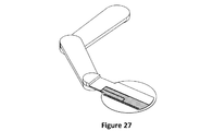
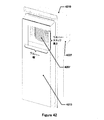
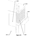
半導体処理設備では、半導体ウエハーが、フロント・オープニング・ユニファイド・ポッド(FOUP)を使用して、半導体処理ツールから半導体処理ツールへ搬送されることは一般的である。FOUPは、典型的に、たとえば、ハウジングの側壁部から突出する棚など、間隔を空けて配置されたスタックの中に複数のウエハーを支持するウエハー支持構造体の垂直スタックを備えるキャリア・ハウジングを含む。典型的なFOUPは、25個または30個のウエハーを保持することが可能であるが、他の保持数を有するFOUPも可能である。ウエハーは、典型的に、ウエハー・ハンドリング・ロボットが、スタックにおける隣接するウエハー同士の間にエンド・エフェクターを挿入し、ウエハーを持ち上げ、他のウエハーを妨害することなくウエハーを引き出すことができるように、FOUPの中に間隔を空けて配置されているにおける。 In semiconductor processing equipment, it is common for semiconductor wafers to be transferred from a semiconductor processing tool to a semiconductor processing tool using a front opening unified pod (FOUP). A FOUP typically includes a carrier housing with a vertical stack of wafer support structures that support a plurality of wafers in a spaced-apart stack, such as, for example, a shelf protruding from the sidewall of the housing. . A typical FOUP can hold 25 or 30 wafers, but FOUPs with other holding numbers are also possible. Wafers typically allow a wafer handling robot to insert an end effector between adjacent wafers in a stack, lift the wafer, and withdraw the wafer without interfering with other wafers. , Are arranged in the FOUP at intervals.
FOUPは、典型的に、取り外し可能なFOUPドアを含み、取り外し可能なFOUPドアは、周囲環境からFOUPをシールするために使用され得る。FOUPは、半導体処理設備の中の周囲環境の条件から、たとえば、水分または酸素から、FOUPの中のウエハーを保護する、何らかのバッファー・ガスで充填され得る。バッファー・ガスは、たとえば、きれいな乾燥空気、窒素、または、設備空気よりも望ましいと考えられる任意の他のガスであることが可能である。しかし、バッファー・ガスは、典型的にEFEMを介して流される設備空気と同じではない。 A FOUP typically includes a removable FOUP door, which can be used to seal the FOUP from the surrounding environment. The FOUP may be filled with some buffer gas that protects the wafer in the FOUP from ambient environmental conditions in the semiconductor processing facility, for example, from moisture or oxygen. The buffer gas can be, for example, clean dry air, nitrogen, or any other gas that may be more desirable than equipment air. However, buffer gas is not the same as facility air that is typically flowed through EFEM.
本明細書で説明されている主題の1つまたは複数の実装形態の詳細は、添付の図面および下記の説明において述べられている。他の特徴、態様、および利点は、説明、図面、および特許請求の範囲から明らかになることとなる。 The details of one or more implementations of the subject matter described in this specification are set forth in the accompanying drawings and the description below. Other features, aspects, and advantages will be apparent from the description, drawings, and claims.
いくつかの実装形態では、ロボット・アームと、ロボット・アームに取り付けられているエンド・エフェクターであって、ロボット・アームの移動の間、半導体ウエハーを支持するように構成されている、エンド・エフェクターと、半導体ウエハーがエンド・エフェクターによって支持されているときに、半導体ウエハーの対向表面にわたってバッファー・ガスを流すように構成されているバッファー・ガス・ディストリビューターとを備え得る装置が提供され得る。そのような実装形態では、バッファー・ガス・ディストリビューターは、ロボット・アームの少なくともいくつかの移動の間、エンド・エフェクターと縦に並んで移動するように構成され得、バッファー・ガス・ディストリビューターおよびエンド・エフェクターは、垂直方向の軸線に沿って間隔を空けて配置され得、エンド・エフェクターおよびバッファー・ガス・ディストリビューターが、半導体ウエハーに対して垂直な軸線に沿って配列された半導体ウエハーのスタックの中へ挿入可能であり、バッファー・ガス・ディストリビューターおよびエンド・エフェクターは、半導体ウエハーのスタックにおけるウエハー間ギャップ内に適合するようにそれぞれサイズ決めされ得る。 In some implementations, an end effector that is configured to support a semiconductor wafer during movement of the robot arm and a robot arm and an end effector attached to the robot arm. And a buffer gas distributor configured to flow buffer gas across the opposing surface of the semiconductor wafer when the semiconductor wafer is supported by the end effector. In such implementations, the buffer gas distributor may be configured to move in tandem with the end effector during at least some movements of the robotic arm, the buffer gas distributor and The end effector may be spaced along a vertical axis, and a stack of semiconductor wafers in which the end effector and buffer gas distributor are arranged along an axis perpendicular to the semiconductor wafer The buffer gas distributor and the end effector can each be sized to fit within an inter-wafer gap in a stack of semiconductor wafers.
いくつかの追加的なそのような実装形態では、バッファー・ガス・ディストリビューターは、エンド・エフェクターに対して間隙を空けて固定され得、ロボット・アームのすべての移動の間、エンド・エフェクターと縦に並んで移動することが可能である。 In some additional such implementations, the buffer gas distributor can be fixed with a gap relative to the end effector, and the end effector can be It is possible to move side by side.
いくつかの追加的なまたは代替的なそのような実装形態では、半導体ウエハーのアレイは、フロント・オープニング・ユニファイド・ポッド、ウエハー・ストッカー、ウエハー・バッファー、ロード・ロック、マルチ・ウエハー・カセット、および、サイド・バイ・サイド・マルチ・ウエハー・カセットなどのような、1つまたは複数の機器におけるウエハー支持機能部によって画定されるウエハー間アレイ・間隔を有することが可能である。いくつかのさらなるそのような実装形態では、半導体ウエハーがエンド・エフェクターおよび1つまたは複数の機器のウエハー支持機能部の両方によって支持され、ならびに、バッファー・ガス・ディストリビューターが半導体ウエハーに対して垂直な第1の方向に沿って目視されたときに、半導体ウエハーと重なるバッファー・ガス・ディストリビューターの部分は、第1の方向に沿って目視されたときに、1つまたは複数の機器におけるウエハー支持機能部と重ならない形状を有することが可能である。いくつかのさらなるそのような実装形態では、各ウエハー支持機能部は、エンド・エフェクターの方を向くギャップを有することが可能であり、バッファー・ガス・ディストリビューターは、ギャップよりも小さい、バッファー・ガス・ディストリビューターの長軸に対して垂直な方向の幅を有することが可能である。 In some additional or alternative such implementations, the array of semiconductor wafers includes a front opening unified pod, a wafer stocker, a wafer buffer, a load lock, a multi-wafer cassette, And it is possible to have an inter-wafer array spacing defined by wafer support features in one or more instruments, such as side-by-side multi-wafer cassettes. In some further such implementations, the semiconductor wafer is supported by both the end effector and the wafer support function of one or more instruments, and the buffer gas distributor is perpendicular to the semiconductor wafer. The portion of the buffer gas distributor that overlaps the semiconductor wafer when viewed along the first direction is wafer support in one or more devices when viewed along the first direction. It is possible to have a shape that does not overlap with the functional part. In some further such implementations, each wafer support feature can have a gap facing the end effector, and the buffer gas distributor can be a buffer gas smaller than the gap. It is possible to have a width in a direction perpendicular to the long axis of the distributor.
装置のいくつかの実装形態では、バッファー・ガス・ディストリビューターは、半導体ウエハーがエンド・エフェクターによって支持されているときに半導体ウエハーと重なる領域において、半導体ウエハーに対して垂直な方向に沿って、9mm以下の厚さになっていることが可能であり、バッファー・ガス・ディストリビューターは、エンド・エフェクターを向く底部表面と、バッファー・ガス・ディストリビューターの底部表面と反対側方向に向く上部表面と、バッファー・ガス・ディストリビューターの上部表面とバッファー・ガス・ディストリビューターの底部表面との間に広がる1つまたは複数の側部表面と、バッファー・ガス・ディストリビューターの底部表面の上に配置されている1つまたは複数の第1のガス・ディストリビューション・ポートと、バッファー・ガス・ディストリビューターの側部表面の上に配置されている複数の第2のガス・ディストリビューション・ポートと、1つまたは複数の第1のガス・ディストリビューション・ポートおよび複数の第2のガス・ディストリビューション・ポートにバッファー・ガスを供給するように構成されているガス・ディストリビューション通路とを含むことが可能である。 In some implementations of the apparatus, the buffer gas distributor is 9 mm along a direction perpendicular to the semiconductor wafer in a region that overlaps the semiconductor wafer when the semiconductor wafer is supported by the end effector. The buffer gas distributor can have the following thickness: the bottom surface facing the end effector; the top surface facing away from the bottom surface of the buffer gas distributor; Located on the bottom surface of the buffer gas distributor and one or more side surfaces extending between the top surface of the buffer gas distributor and the bottom surface of the buffer gas distributor One or more first gas distributors A plurality of second gas distribution ports disposed on a side surface of the buffer gas distributor, one or more first gas distribution ports and A gas distribution passage configured to supply buffer gas to the plurality of second gas distribution ports.
装置のいくつかの実装形態では、半導体ウエハーがエンド・エフェクターによって支持され、および、バッファー・ガス・ディストリビューターが半導体ウエハーに対して垂直な第1の方向に沿って目視されたときに、バッファー・ガス・ディストリビューターは、半導体ウエハーのすべてにわたって延在していなくてもよい。 In some implementations of the apparatus, when the semiconductor wafer is supported by the end effector and the buffer gas distributor is viewed along a first direction perpendicular to the semiconductor wafer, the buffer The gas distributor may not extend over all of the semiconductor wafer.
装置のいくつかのさらなるそのような実装形態では、半導体ウエハーがエンド・エフェクターによって支持され、および、バッファー・ガス・ディストリビューターが半導体ウエハーに対して垂直な第1の方向に沿って目視されたときに、バッファー・ガス・ディストリビューターは、半導体ウエハーの中心軸線、および、エンド・エフェクターをロボット・アームに接合する機械的なインターフェースを通過する第2の方向に、半導体ウエハーの直径の少なくとも90%にわたって延在することが可能であり、また、第1の方向および第2の方向の両方に対して垂直な第3の方向に半導体ウエハーの一部にわたって延在することが可能である。 In some further such implementations of the apparatus, when the semiconductor wafer is supported by an end effector and the buffer gas distributor is viewed along a first direction perpendicular to the semiconductor wafer In addition, the buffer gas distributor spans at least 90% of the semiconductor wafer diameter in a second direction through the central axis of the semiconductor wafer and the mechanical interface joining the end effector to the robot arm. It can extend over a portion of the semiconductor wafer in a third direction perpendicular to both the first direction and the second direction.
装置のいくつかの実装形態では、半導体ウエハーがエンド・エフェクターによって支持され、および、半導体ウエハーに対して平行な軸線に沿って目視されたときに、バッファー・ガス・ディストリビューターの少なくとも最も外側の半分部は、半導体ウエハーと重ならないように構成され得る。 In some implementations of the apparatus, the semiconductor wafer is supported by the end effector and at least the outermost half of the buffer gas distributor when viewed along an axis parallel to the semiconductor wafer. The part may be configured not to overlap the semiconductor wafer.
装置のいくつかの実装形態では、半導体ウエハーがエンド・エフェクターによって支持されているときに半導体ウエハーの上に延在するバッファー・ガス・ディストリビューターの部分は、半導体ウエハーに対して平行な軸線に沿って目視されたときに、半導体ウエハーと重ならないように構成され得る。 In some implementations of the apparatus, the portion of the buffer gas distributor that extends over the semiconductor wafer when the semiconductor wafer is supported by the end effector is along an axis parallel to the semiconductor wafer. It can be configured not to overlap the semiconductor wafer when visually observed.
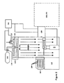
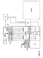
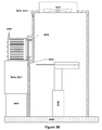
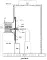
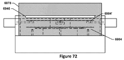
いくつかの実装形態では、半導体ウエハーを処理するための装置が提供され得る。そのような実装形態では、装置は、エンクロージャーと、垂直方向の軸線に沿って配列されたN個のウエハー支持構造体を有するマルチ・ウエハー・ストレージ・システムを支持するように構成されているインターフェースと、壁部とを含むことが可能である。ウエハー支持構造体は、直径Dの半導体ウエハーを支持するようにサイズ決めされ得、Nは、1よりも大きい整数であることが可能であり、各半導体ウエハー支持構造体は、アレイにおける任意の隣接する1つまたは複数のウエハー支持構造体から平均距離dだけ間隔を空けて配置され得る。壁部は、Dよりも大きい幅および(N−1)・dよりも低い高さを有する水平スロットを含むことが可能であり、壁部は、(2・N−1)・dよりも高い高さを有することが可能であり、装置は、水平スロットとインターフェースの間で、垂直方向の軸線に沿って、相対的な平行移動を提供するように構成され得、壁部は、マルチ・ウエハー・ストレージ・システムの開口部に近接するように位置決めされ得、マルチ・ウエハー・ストレージ・システムがインターフェースによって支持されているときに、半導体ウエハーは、開口部を介して、マルチ・ウエハー・ストレージ・システムの中へロードされ得るか、または、マルチ・ウエハー・ストレージ・システムからアンロードされ得、半導体ウエハーが、壁部を介して、マルチ・ウエハー・ストレージ・システムの中へロードされ得るか、または、マルチ・ウエハー・ストレージ・システムからアンロードされ得る壁部は、マルチ・ウエハー・ストレージ・システムがインターフェースによって支持されているときに、マルチ・ウエハー・ストレージ・システムの内部空間とエンクロージャーの内部空間との間に流量制限バリアを提供することが可能である。 In some implementations, an apparatus for processing a semiconductor wafer may be provided. In such an implementation, the apparatus includes an enclosure and an interface configured to support a multi-wafer storage system having N wafer support structures arranged along a vertical axis. , And walls. The wafer support structure may be sized to support a semiconductor wafer of diameter D, N may be an integer greater than 1, and each semiconductor wafer support structure may be any adjacent neighbor in the array. One or more wafer support structures that are spaced apart by an average distance d. The wall may include horizontal slots having a width greater than D and a height less than (N−1) · d, and the wall is higher than (2 · N−1) · d. And the apparatus can be configured to provide relative translation along the vertical axis between the horizontal slot and the interface, and the wall is a multi-wafer The semiconductor wafer can be positioned close to the opening of the storage system and the multi-wafer storage system is supported by the interface through the opening of the multi-wafer storage system Can be loaded into or unloaded from the multi-wafer storage system so that the semiconductor wafer can be Walls that can be loaded into or unloaded from the multi-wafer storage system can be loaded into the multi-wafer storage system when the multi-wafer storage system is supported by the interface. A flow restriction barrier can be provided between the internal space of the storage system and the internal space of the enclosure.
いくつかのそのような実装形態では、装置は、第1のバッファー・ガスをエンクロージャーの中へ供給するように構成されている第1のバッファー・ガス・ポートと、マルチ・ウエハー・ストレージ・システムがインターフェースによって支持されているときに、第2のバッファー・ガスをマルチ・ウエハー・ストレージ・システムの中へ供給するように構成されている第2のバッファー・ガス・ポートとをさらに含むことが可能である。 In some such implementations, the apparatus includes a first buffer gas port configured to supply a first buffer gas into the enclosure, and a multi-wafer storage system. A second buffer gas port configured to supply a second buffer gas into the multi-wafer storage system when supported by the interface. is there.
いくつかの追加的なまたは代替的な実装形態では、装置は、ロボット・アームと、ロボット・アームに取り付けられ、ロボット・アームの移動の間、半導体ウエハーを支持するように構成されている、エンド・エフェクターと、半導体ウエハーがエンド・エフェクターによって支持されているときに、半導体ウエハーの対向表面にわたって第1のバッファー・ガスを流すように構成されているバッファー・ガス・ディストリビューターとをさらに含むことが可能である。そのような実装形態では、バッファー・ガス・ディストリビューターは、ロボット・アームの少なくともいくつかの移動の間、エンド・エフェクターと縦に並んで移動するように構成され得、バッファー・ガス・ディストリビューターおよびエンド・エフェクターは、間隔を空けて配置され得、マルチ・ウエハー・ストレージ・システムが、装置の中に設置されており、半導体ウエハーをストックしているときに、エンド・エフェクターおよびバッファー・ガス・ディストリビューターは、水平スロットを介して、ウエハー支持構造体のアレイによって支持されている半導体ウエハーのアレイの中へ挿入可能であり、バッファー・ガス・ディストリビューターおよびエンド・エフェクターは、半導体ウエハーのアレイにおけるウエハー間ギャップ内に適合するようにそれぞれサイズ決めされ得る。 In some additional or alternative implementations, the apparatus includes a robot arm and an end attached to the robot arm and configured to support a semiconductor wafer during movement of the robot arm. Further comprising an effector and a buffer gas distributor configured to flow a first buffer gas over the opposing surface of the semiconductor wafer when the semiconductor wafer is supported by the end effector. Is possible. In such implementations, the buffer gas distributor may be configured to move in tandem with the end effector during at least some movements of the robotic arm, the buffer gas distributor and End effectors can be spaced apart, and when the multi-wafer storage system is installed in equipment and stocks semiconductor wafers, the end effector and buffer gas distribution Can be inserted through a horizontal slot into an array of semiconductor wafers supported by an array of wafer support structures, and buffer gas distributors and end effectors can be inserted into the wafers in the array of semiconductor wafers. Between Each to fit within flops may be sized.
いくつかの実装形態では、装置は、第2のバッファー・ガスをエンクロージャーの中へ供給するように構成されている第1のバッファー・ガス・ポートと、マルチ・ウエハー・ストレージ・システムがインターフェースによって支持されているときに、第3のバッファー・ガスをマルチ・ウエハー・ストレージ・システムの中へ供給するように構成されている第2のバッファー・ガス・ポートとをさらに含むことが可能である。 In some implementations, the apparatus includes a first buffer gas port configured to supply a second buffer gas into the enclosure and a multi-wafer storage system supported by the interface. A second buffer gas port configured to supply a third buffer gas into the multi-wafer storage system when being configured.
いくつかの実装形態では、第1のバッファー・ガス、第2のバッファー・ガス、および、第3のバッファー・ガスは、設備窒素ガス供給源によってすべて提供され得る。 In some implementations, the first buffer gas, the second buffer gas, and the third buffer gas may all be provided by an equipment nitrogen gas source.
いくつかの実装形態では、バッファー・ガス・ディストリビューターは、エンド・エフェクターに対して間隙を空けて固定され得、ロボット・アームのすべての移動の間、エンド・エフェクターと縦に並んで移動することが可能である。 In some implementations, the buffer gas distributor may be fixed with a gap to the end effector and move vertically alongside the end effector during all movements of the robot arm. Is possible.
いくつかの実装形態では、装置は、マルチ・ウエハー・ストレージ・システムをさらに含むことが可能であり、マルチ・ウエハー・ストレージ・システムは、インターフェースによって支持され得る。 In some implementations, the apparatus can further include a multi-wafer storage system, and the multi-wafer storage system can be supported by an interface.
いくつかの実装形態では、マルチ・ウエハー・ストレージ・システムは、フロント・オープニング・ユニファイド・ポッド、ウエハー・ストッカー、ウエハー・バッファー、マルチ・ウエハー・カセット、またはロード・ロックであることが可能である。 In some implementations, the multi-wafer storage system can be a front-opening unified pod, wafer stocker, wafer buffer, multi-wafer cassette, or load lock .
いくつかの実装形態では、装置は、駆動機構をさらに含むことが可能であり、駆動機構は、垂直方向の軸線に沿ってエンクロージャーに対して壁部を平行移動させるように構成されている。他のまたは追加的なそのような実装形態では、駆動機構は、垂直方向の軸線に沿ってエンクロージャーに対してインターフェースを平行移動させるように、または、インターフェースおよび壁部の両方を互いに対してそのような方向に平行移動させるように構成され得る。 In some implementations, the apparatus can further include a drive mechanism that is configured to translate the wall relative to the enclosure along a vertical axis. In other or additional such implementations, the drive mechanism translates the interface relative to the enclosure along a vertical axis, or so both the interface and the wall relative to each other. Can be configured to translate in any direction.
いくつかの実装形態では、装置は、ロボット・アームと、ロボット・アームに取り付けられ、ロボット・アームの移動の間、半導体ウエハーを支持するように構成されている、エンド・エフェクターとをさらに含むことが可能である。そのような実装形態では、水平スロットは、垂直方向の軸線に沿って第1の寸法を有する中間部分を有することが可能であり、第1の寸法は、中間部分とは異なる位置に位置する水平スロットの側方部分の垂直方向の軸線に沿う、対応する第2の寸法よりも大きくなっており、中間部分は、ロボット・アームの移動の間、半導体ウエハーを支持するように構成されているエンド・エフェクターの部分の幅よりも広くなっていることが可能であり、エンド・エフェクターは、半導体ウエハーがエンド・エフェクターによって支持されているときに、半導体ウエハーに接触するように構成されているウエハー接触表面を有することが可能であり、エンド・エフェクターは、1つまたは複数の第1の底部表面を有することが可能であり、1つまたは複数の第1の底部表面は、ウエハー接触表面から離れる方向を向いており、1つまたは複数の第1の底部表面は、半導体ウエハーがエンド・エフェクターによって支持され、および、エンド・エフェクターが半導体ウエハーに対して垂直な方向に沿って目視されるときに、半導体ウエハーの外周部内に配置されており、第1の寸法は、第2の寸法に、エンド・エフェクターの1つまたは複数の第1の底部表面の最も下側にある表面とウエハー接触表面との間の垂直方向の距離を加えた寸法よりも大きいか、または、それに等しくなっていることが可能である。 In some implementations, the apparatus further includes a robot arm and an end effector attached to the robot arm and configured to support the semiconductor wafer during movement of the robot arm. Is possible. In such an implementation, the horizontal slot can have an intermediate portion having a first dimension along a vertical axis, the first dimension being a horizontal position located at a different position than the intermediate portion. An end that is larger than the corresponding second dimension along the vertical axis of the side portion of the slot and the intermediate portion is configured to support the semiconductor wafer during movement of the robot arm. The wafer contact can be wider than the width of the effector portion, and the end effector is configured to contact the semiconductor wafer when the semiconductor wafer is supported by the end effector. The end effector can have one or more first bottom surfaces, one or more The first bottom surface of the number faces away from the wafer contact surface, the one or more first bottom surfaces are supported by the end effector on the semiconductor wafer, and the end effector is on the semiconductor wafer. Is positioned within the outer periphery of the semiconductor wafer when viewed along a direction perpendicular to the first dimension, wherein the first dimension is a second dimension and the one or more first effectors of the end effector. It can be greater than or equal to the dimension plus the vertical distance between the bottom surface of the bottom surface and the wafer contact surface.
いくつかのそのような実装形態では、エンド・エフェクターは、1つまたは複数の第1の上側表面を有することが可能であり、1つまたは複数の第1の上側表面は、1つまたは複数の第1の底部表面から離れる方向を向いており、1つまたは複数の第1の上側表面は、半導体ウエハーをマルチ・ウエハー・ストレージ・システムに載置するためにエンド・エフェクターが使用されるときに、水平スロットを通り、第1の寸法は、エンド・エフェクターの1つまたは複数の第1の底部表面の最も下側にある表面と、エンド・エフェクターの1つまたは複数の第1の上側表面の最上部表面との間の垂直方向の距離よりも大きいか、または、それに等しくなっていることが可能である。 In some such implementations, the end effector can have one or more first upper surfaces, and the one or more first upper surfaces can include one or more When facing away from the first bottom surface, the one or more first upper surfaces are used when the end effector is used to place the semiconductor wafer on the multi-wafer storage system. , Through the horizontal slot, the first dimension is the lowest surface of the one or more first bottom surfaces of the end effector and the one or more first upper surfaces of the end effector. It can be greater than or equal to the vertical distance between the top surface.
装置のいくつかの実装形態では、装置は、半導体ウエハーがエンド・エフェクターによって支持されているときに、半導体ウエハーの対向表面にわたってバッファー・ガスを流すように構成されているバッファー・ガス・ディストリビューターをさらに含むことが可能である。バッファー・ガス・ディストリビューターは、ロボット・アームの少なくともいくつかの移動の間、エンド・エフェクターと縦に並んで移動するように構成され得、バッファー・ガス・ディストリビューターおよびエンド・エフェクターは、間隔を空けて配置され得、マルチ・ウエハー・ストレージ・システムが、装置の中に設置されており、半導体ウエハーをストックしているときに、エンド・エフェクターおよびバッファー・ガス・ディストリビューターは、ウエハー支持構造体のアレイによって支持されている半導体ウエハーのアレイの中へ挿入可能であり、バッファー・ガス・ディストリビューターおよびエンド・エフェクターは、半導体ウエハーのアレイにおけるウエハー間ギャップ内に適合するようにそれぞれサイズ決めされ得、バッファー・ガス・ディストリビューターは、1つまたは複数の第1の上側表面を有することが可能であり、1つまたは複数の第1の上側表面は、1つまたは複数の第1の底部表面から離れる方向を向いており、1つまたは複数の第1の上側表面は、半導体ウエハーをマルチ・ウエハー・ストレージ・システムから除去するためにエンド・エフェクターが使用されるときに、水平スロットを通り、第1の寸法は、エンド・エフェクターの1つまたは複数の第1の底部表面の最も下側にある表面と、バッファー・ガス・ディストリビューターの1つまたは複数の第1の上側表面の最上部表面との間の垂直方向の距離よりも大きいか、または、それに等しくなっていることが可能である。 In some implementations of the apparatus, the apparatus includes a buffer gas distributor configured to flow buffer gas across the opposing surface of the semiconductor wafer when the semiconductor wafer is supported by the end effector. Further inclusions are possible. The buffer gas distributor may be configured to move in tandem with the end effector during at least some movements of the robot arm, the buffer gas distributor and the end effector being spaced apart. When the multi-wafer storage system is installed in the apparatus and stocking semiconductor wafers, the end effector and buffer gas distributor can be placed in the wafer support structure. The buffer gas distributor and the end effector can be sized to fit within the inter-wafer gap in the array of semiconductor wafers. The buffer gas distributor can have one or more first upper surfaces, and the one or more first upper surfaces are separated from the one or more first bottom surfaces. And the one or more first upper surfaces pass through the horizontal slot when the end effector is used to remove the semiconductor wafer from the multi-wafer storage system, Of the end effector one or more first bottom surfaces and the top surface of the buffer gas distributor one or more first upper surfaces. It can be greater than or equal to the vertical distance between them.
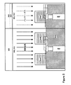
いくつかの実装形態では、異なる位置に位置決めされている複数のウエハー処理チャンバーと、異なる位置においてウエハー処理チャンバーを支持するシャーシーと、1つまたは複数のマルチ・ウエハー・カセットであって、各マルチ・ウエハー・カセットは、垂直方向の軸線に沿って配置されているN個のウエハー支持構造体を有している、1つまたは複数のマルチ・ウエハー・カセットと、それぞれが、移動の間、半導体ウエハーを支持するように構成されているエンド・エフェクターを有する1つまたは複数のロボット・アームと、少なくとも1つのバッファー・ガス・マイクロクライメイト・システムとを含む装置が提供され得る。バッファー・ガス・マイクロクライメイト・システムは、1つまたは複数のマルチ・ウエハー・カセットのそれぞれの一部であり得る少なくとも1つのスロット・ドア・メカニズム、1つまたは複数のエンド・エフェクターによって支持されている半導体ウエハーの対向表面にわたってバッファー・ガスを流すように構成されている1つまたは複数のバッファー・ガス・ディストリビューター、または、1つまたは複数のマルチ・ウエハー・カセットのそれぞれの一部であり得る少なくとも1つのスロット・ドア・メカニズム、および、1つまたは複数のエンド・エフェクターによって支持されている半導体ウエハーの対向表面にわたってバッファー・ガスを流すように構成されている1つまたは複数のバッファー・ガス・ディストリビューターの両方を含むことが可能である。そのような実装形態では、1つまたは複数のロボット・アームは、1つまたは複数のマルチ・ウエハー・カセットから複数のウエハー処理チャンバーへ、および、1つまたは複数のマルチ・ウエハー・カセットへ、半導体ウエハーを搬送するように構成され得、ウエハー支持構造体は、直径Dの半導体ウエハーを支持するようにサイズ決めされ得、Nは、1よりも大きい整数であることが可能であり、各半導体ウエハー支持構造体は、アレイにおける任意の隣接する1つまたは複数のウエハー支持構造体から平均距離dだけ間隔を空けて配置され得る。 In some implementations, a plurality of wafer processing chambers positioned at different locations, a chassis that supports the wafer processing chambers at different locations, and one or more multi-wafer cassettes, each multi- The wafer cassette has N wafer support structures arranged along a vertical axis, and one or more multi-wafer cassettes, each of which is a semiconductor wafer during movement There may be provided an apparatus including one or more robotic arms having end effectors configured to support the at least one buffer gas microclimate system. The buffer gas microclimate system is supported by at least one slot door mechanism, one or more end effectors that may be part of each of one or more multi-wafer cassettes. Can be part of one or more buffer gas distributors, or each of one or more multi-wafer cassettes configured to flow buffer gas across the opposing surface of a semiconductor wafer At least one slot door mechanism and one or more buffer gas configured to flow buffer gas across the opposing surface of the semiconductor wafer supported by the one or more end effectors; Distribution It can include both over. In such an implementation, one or more robotic arms are connected to the semiconductor from one or more multi-wafer cassettes to a plurality of wafer processing chambers and to one or more multi-wafer cassettes. The wafer support structure can be configured to transport a wafer, the wafer support structure can be sized to support a semiconductor wafer of diameter D, and N can be an integer greater than 1, each semiconductor wafer The support structure may be spaced an average distance d from any adjacent one or more wafer support structures in the array.
装置のいくつかの実装形態では、少なくとも1つのバッファー・ガス・マイクロクライメイト・システムは、少なくとも1つのスロット・ドア・メカニズムを含むことが可能であり、少なくとも1つのスロット・ドア・メカニズムは、1つまたは複数のマルチ・ウエハー・カセットのそれぞれの一部であることが可能である。そのような実装形態では、各マルチ・ウエハー・カセットは、前面開口部を有することが可能であり、前面開口部は、ウエハーがマルチ・ウエハー・カセットの中へ挿入されることまたはマルチ・ウエハー・カセットから引き出されることを可能にするようにサイズ決めされており、各スロット・ドア・メカニズムは、Dよりも大きい幅および(N−1)・dよりも低い高さを有する水平スロットを備えるドアと、機械的な入力に応答して、マルチ・ウエハー・カセットのウエハー支持構造体に対して垂直方向にドアを平行移動させるように構成されている駆動機構であって、スロット・ドアは、マルチ・ウエハー・カセットの一部である、駆動機構を含むことが可能である。各ドアは、(2・N−1)・dよりも高い高さを有することが可能であり、各ドアは、マルチ・ウエハー・カセットの前面開口部の前方に位置決めされ得、そのドアは、マルチ・ウエハー・カセットの一部である。 In some implementations of the apparatus, the at least one buffer gas microclimate system can include at least one slot door mechanism, wherein the at least one slot door mechanism is 1 It can be part of each of one or more multi-wafer cassettes. In such an implementation, each multi-wafer cassette can have a front opening that is inserted into the multi-wafer cassette or the multi-wafer cassette. Door sized to allow it to be pulled out of the cassette, each slot door mechanism comprising a horizontal slot having a width greater than D and a height less than (N-1) · d And a drive mechanism configured to translate the door in a direction perpendicular to the wafer support structure of the multi-wafer cassette in response to mechanical input, wherein the slot door is It can include a drive mechanism that is part of the wafer cassette. Each door can have a height greater than (2 · N−1) · d, and each door can be positioned in front of the front opening of the multi-wafer cassette, Part of a multi-wafer cassette.
いくつかの実装形態では、少なくとも1つのバッファー・ガス・マイクロクライメイト・システムは、1つまたは複数のエンド・エフェクターによって支持されている半導体ウエハーの対向表面にわたってバッファー・ガスを流すように構成されている1つまたは複数のバッファー・ガス・ディストリビューターを含むことが可能である。そのような実装形態では、1つまたは複数のバッファー・ガス・ディストリビューターのそれぞれは、1つまたは複数のエンド・エフェクターのうちの異なる1つに関連付けられ得、各バッファー・ガス・ディストリビューターは、ロボット・アームの少なくともいくつかの移動の間、関連付けられたエンド・エフェクターと縦に並んで移動するように構成され得、関連付けられたエンド・エフェクターは、ロボット・アームの一部であり、各バッファー・ガス・ディストリビューターおよび関連付けられたエンド・エフェクターは、間隔を空けて配置され得、そのバッファー・ガス・ディストリビューターおよび関連付けられたエンド・エフェクターは、N個の半導体ウエハーがN個のウエハー支持構造体によって支持されているときに、N個のウエハー支持構造体によって支持されているN個の半導体ウエハーのスタックの中へ挿入可能であり、各バッファー・ガス・ディストリビューターおよび関連付けられたエンド・エフェクターは、N個の半導体ウエハーのスタックにおけるウエハー間ギャップ内に適合するようにそれぞれサイズ決めされ得る。 In some implementations, the at least one buffer gas microclimate system is configured to flow buffer gas across an opposing surface of a semiconductor wafer supported by one or more end effectors. It is possible to include one or more buffer gas distributors. In such an implementation, each of the one or more buffer gas distributors may be associated with a different one of the one or more end effectors, each buffer gas distributor being During at least some movements of the robot arm, it may be configured to move in tandem with the associated end effector, the associated end effector being part of the robot arm and each buffer The gas distributor and associated end effector can be spaced apart, the buffer gas distributor and associated end effector comprising N semiconductor wafers and N wafer support structures; When supported by the body, Insertable into a stack of N semiconductor wafers supported by a single wafer support structure, each buffer gas distributor and associated end effector in a stack of N semiconductor wafers Each may be sized to fit within the inter-wafer gap.
1つまたは複数のバッファー・ガス・ディストリビューターを有する装置のいくつかの実装形態では、少なくとも1つのバッファー・ガス・マイクロクライメイト・システムは、また、少なくとも1つのスロット・ドア・メカニズムを含むことが可能であり、少なくとも1つのスロット・ドア・メカニズムは、1つまたは複数のマルチ・ウエハー・カセットのそれぞれの一部であることが可能である。そのような実装形態では、各マルチ・ウエハー・カセットは、前面開口部を有することが可能であり、前面開口部は、ウエハーがマルチ・ウエハー・カセットの中へ挿入されることまたはマルチ・ウエハー・カセットから引き出されることを可能にするようにサイズ決めされており、各スロット・ドア・メカニズムは、Dよりも大きい幅および(N−1)・dよりも低い高さを有する水平スロットを備えるドアと、機械的な入力に応答して、マルチ・ウエハー・カセットのウエハー支持構造体に対して垂直方向にドアを平行移動させるように構成されている駆動機構であって、スロット・ドアは、マルチ・ウエハー・カセットの一部である、駆動機構を含むことが可能である。各ドアは、(2・N−1)・dよりも高い高さを有することが可能であり、各ドアは、マルチ・ウエハー・カセットの前面開口部の前方に位置決めされ得、そのドアは、マルチ・ウエハー・カセットの一部である。 In some implementations of an apparatus having one or more buffer gas distributors, the at least one buffer gas microclimate system may also include at least one slot door mechanism. Yes, the at least one slot door mechanism can be part of each of one or more multi-wafer cassettes. In such an implementation, each multi-wafer cassette can have a front opening that is inserted into the multi-wafer cassette or the multi-wafer cassette. Door sized to allow it to be pulled out of the cassette, each slot door mechanism comprising a horizontal slot having a width greater than D and a height less than (N-1) · d And a drive mechanism configured to translate the door in a direction perpendicular to the wafer support structure of the multi-wafer cassette in response to mechanical input, wherein the slot door is It can include a drive mechanism that is part of the wafer cassette. Each door can have a height greater than (2 · N−1) · d, and each door can be positioned in front of the front opening of the multi-wafer cassette, Part of a multi-wafer cassette.
装置のいくつかの実装形態では、装置は、水平ウエハー・カセット・コンベヤーをさらに含むことが可能であり、水平ウエハー・カセット・コンベヤーは、1つまたは複数のマルチ・ウエハー・カセットのうちの少なくとも1つを受け入れるように、および、水平位置同士の間で、水平方向の軸線に沿って、受け入れられた1つまたは複数のマルチ・ウエハー・カセットのうちの少なくとも1つを平行移動させるように構成されている。そのような実装形態では、ウエハー処理チャンバーは、水平ウエハー・カセット・コンベヤーのいずれかの側において、間隔を空けて配置された位置に位置決めされ得、1つまたは複数のロボット・アームのうちの第1のロボット・アームは、第1のマルチ・ウエハー・カセットが少なくとも水平位置のうちの第1の水平位置に位置決めされているときに、1つまたは複数のマルチ・ウエハー・カセットのうちの第1のマルチ・ウエハー・カセットと、ウエハー処理チャンバーの第1のウエハー処理チャンバー、ウエハー処理チャンバーの第2のウエハー処理チャンバー、ウエハー処理チャンバーの第3のウエハー処理チャンバー、および、ウエハー処理チャンバーの第4のウエハー処理チャンバーの間で、半導体ウエハーを搬送するように構成され得る。第1のウエハー処理チャンバーおよび第2のウエハー処理チャンバーは、水平ウエハー・カセット・コンベヤーの第1の側に配置され得、第3のウエハー処理チャンバーおよび第4のウエハー処理チャンバーは、水平ウエハー・カセット・コンベヤーの第2の側に配置され得、水平ウエハー・カセット・コンベヤーの第1の側は、水平ウエハー・カセット・コンベヤーの第2の側に対して、水平ウエハー・カセット・コンベヤーの反対側にあることが可能である。 In some implementations of the apparatus, the apparatus can further include a horizontal wafer cassette conveyor, wherein the horizontal wafer cassette conveyor is at least one of the one or more multi-wafer cassettes. And at least one of the received multi-wafer cassettes is translated between horizontal positions and along a horizontal axis between horizontal positions. ing. In such an implementation, the wafer processing chamber may be positioned at spaced locations on either side of the horizontal wafer cassette conveyor, and the first of the one or more robot arms. One robotic arm is the first of the one or more multi-wafer cassettes when the first multi-wafer cassette is positioned at least in a first horizontal position of the horizontal positions. A multi-wafer cassette, a first wafer processing chamber of the wafer processing chamber, a second wafer processing chamber of the wafer processing chamber, a third wafer processing chamber of the wafer processing chamber, and a fourth of the wafer processing chambers To transport semiconductor wafers between wafer processing chambers It may be made. The first wafer processing chamber and the second wafer processing chamber may be disposed on a first side of a horizontal wafer cassette conveyor, the third wafer processing chamber and the fourth wafer processing chamber being a horizontal wafer cassette. Can be located on the second side of the conveyor, the first side of the horizontal wafer cassette conveyor is opposite the second side of the horizontal wafer cassette conveyor, opposite the horizontal wafer cassette conveyor It is possible that there is.
装置のいくつかのそのような実装形態では、装置は、1つまたは複数の垂直ウエハー・カセット・コンベヤーをさらに含むことが可能である。各垂直ウエハー・カセット・コンベヤーは、水平位置のうちの異なる1つに関連付けられ得、1つまたは複数の垂直ウエハー・カセット・コンベヤーのうちの第1の垂直ウエハー・カセット・コンベヤーは、第1の水平位置に関連付けられ得る。各垂直ウエハー・カセット・コンベヤーは、1つまたは複数の機械的なインターフェースを含むことが可能であり、各垂直ウエハー・カセット・コンベヤーのそれぞれの機械的なインターフェースは、その機械的なインターフェースがそのマルチ・ウエハー・カセットと垂直方向に整合させられているとき、および、そのマルチ・ウエハー・カセットが、その垂直ウエハー・カセット・コンベヤーに関連付けられた水平位置に位置決めされ、ベースラインの垂直位置において、水平ウエハー・カセット・コンベヤーによって支持されているとき、1つまたは複数のマルチ・ウエハー・カセットのうちのマルチ・ウエハー・カセットと接続するように構成され得る。各垂直ウエハー・カセット・コンベヤーは、その垂直ウエハー・カセット・コンベヤーの中に含まれている1つまたは複数の機械的なインターフェース、および、それらの1つまたは複数の機械的なインターフェースが接続されているそれぞれのマルチ・ウエハー・カセットを、垂直方向の軸線に沿って、1つまたは複数の垂直カセット位置へ平行移動させるように構成され得、1つまたは複数の垂直カセット位置は、ベースラインの垂直位置の高さ以外の高さにおける垂直位置にあることが可能である。そのような実装形態では、第1のロボット・アームは、第1のマルチ・ウエハー・カセットが第1の水平位置に位置決めされ、および、第1の垂直ウエハー・カセット・コンベヤーによって、1つまたは複数の垂直カセット位置のうちの第1の垂直カセット位置にも位置決めされているときに、第1のマルチ・ウエハー・カセットと、第1のウエハー処理チャンバー、第2のウエハー処理チャンバー、第3のウエハー処理チャンバー、および第4のウエハー処理チャンバーの間で、半導体ウエハーを搬送するように構成され得る。 In some such implementations of the apparatus, the apparatus can further include one or more vertical wafer cassette conveyors. Each vertical wafer cassette conveyor may be associated with a different one of the horizontal positions, the first vertical wafer cassette conveyor of the one or more vertical wafer cassette conveyors being the first Can be associated with a horizontal position. Each vertical wafer cassette conveyor can include one or more mechanical interfaces, and each mechanical interface of each vertical wafer cassette conveyor has its mechanical interface as its multi- When aligned vertically with the wafer cassette and when the multi-wafer cassette is positioned in a horizontal position associated with the vertical wafer cassette conveyor and in the vertical position of the baseline, When supported by a wafer cassette conveyor, it may be configured to connect with a multi-wafer cassette of one or more multi-wafer cassettes. Each vertical wafer cassette conveyor is connected to one or more mechanical interfaces contained in the vertical wafer cassette conveyor and one or more mechanical interfaces thereof. Each multi-wafer cassette may be configured to translate along a vertical axis to one or more vertical cassette positions, the one or more vertical cassette positions being perpendicular to the baseline It is possible to be in a vertical position at a height other than the height of the position. In such an implementation, the first robot arm has one or more first multi-wafer cassettes positioned in a first horizontal position and one or more by a first vertical wafer cassette conveyor. The first multi-wafer cassette, the first wafer processing chamber, the second wafer processing chamber, and the third wafer when the first vertical cassette position is also positioned. A semiconductor wafer may be configured to be transferred between the processing chamber and the fourth wafer processing chamber.
いくつかのさらなるそのような実装形態では、各機械的なインターフェースは、少なくとも1つのバッファー・ガス・ポートを含むことが可能であり、各マルチ・ウエハー・カセットは、少なくとも1つのバッファー・ガス入口部を含むことが可能である。各マルチ・ウエハー・カセットの少なくとも1つのバッファー・ガス入口部は、そのマルチ・ウエハー・カセットがその機械的なインターフェースに接続されているときに、それぞれの機械的なインターフェースの少なくとも1つのバッファー・ガス・ポートに整合することが可能であり、それによって、バッファー・ガスがその少なくとも1つのバッファー・ガス・ポートおよび少なくとも1つのバッファー・ガス入口部を介してそのマルチ・ウエハー・カセットの内部空間へ導入されることを可能にする。 In some further such implementations, each mechanical interface can include at least one buffer gas port, and each multi-wafer cassette has at least one buffer gas inlet. Can be included. At least one buffer gas inlet of each multi-wafer cassette has at least one buffer gas in each mechanical interface when the multi-wafer cassette is connected to the mechanical interface. Can be aligned with the port, whereby buffer gas is introduced into the interior space of the multi-wafer cassette via its at least one buffer gas port and at least one buffer gas inlet Allows to be done.
装置のいくつかの実装形態では、1つまたは複数の垂直ウエハー・カセット・コンベヤーのうちの第2の垂直ウエハー・カセット・コンベヤーが、水平位置のうちの第2の水平位置に関連付けられ得、第1のロボット・アームは、第1の水平位置と第2の水平位置との間に置かれ得、各マルチ・ウエハー・カセットは、後面開口部も含むことが可能であり、後面開口部は、また、半導体ウエハーがそのマルチ・ウエハー・カセットの中へ挿入されることまたはそのマルチ・ウエハー・カセットから引き出されることを可能にするようにサイズ決めされており、後面開口部は、そのマルチ・ウエハー・カセットの前面開口部の反対側にあり、1つまたは複数のマルチ・ウエハー・カセットの各一部であり得る少なくとも1つのスロット・ドア・メカニズムは、それぞれのマルチ・ウエハー・カセットに関して、第2のスロット・ドア・メカニズムを含むことが可能であり、それぞれの第2のスロット・ドア・メカニズムのドアは、マルチ・ウエハー・カセットの後面開口部の前方に位置決めされ得、第2のスロット・ドア・メカニズムは、マルチ・ウエハー・カセットの一部であり、第2のマルチ・ウエハー・カセットは、1つまたは複数のマルチ・ウエハー・カセットのうちの1つであり、第1のロボット・アームは、また、第2のマルチ・ウエハー・カセットが第2の垂直ウエハー・カセット・コンベヤーによって第2の水平位置および第1の垂直カセット位置に位置決めされているときに、第2のマルチ・ウエハー・カセットと、第1のウエハー処理チャンバー、第2のウエハー処理チャンバー、第3のウエハー処理チャンバー、および第4のウエハー処理チャンバーの間で、半導体ウエハーを搬送するように構成され得る。 In some implementations of the apparatus, a second vertical wafer cassette conveyor of the one or more vertical wafer cassette conveyors can be associated with a second of the horizontal positions, One robot arm can be placed between a first horizontal position and a second horizontal position, and each multi-wafer cassette can also include a rear opening, where the rear opening is The semiconductor wafer is sized to allow the semiconductor wafer to be inserted into or withdrawn from the multi-wafer cassette, the rear opening being the multi-wafer At least one slot door that is opposite the front opening of the cassette and may be part of each of one or more multi-wafer cassettes The cannism may include a second slot door mechanism for each multi-wafer cassette, the door of each second slot door mechanism being open to the rear of the multi-wafer cassette. The second slot door mechanism is part of a multi-wafer cassette and the second multi-wafer cassette is one of one or more multi-wafer cassettes. One of them, the first robot arm also has a second multi-wafer cassette positioned at a second horizontal position and a first vertical cassette position by a second vertical wafer cassette conveyor. A second multi-wafer cassette, a first wafer processing chamber, a second wafer, Processing chamber, between the third wafer processing chamber, and a fourth wafer processing chamber may be configured to carry the semiconductor wafer.
装置のいくつかの実装形態では、装置は、1つまたは複数の垂直ロボット・アーム・コンベヤーと、ウエハー処理チャンバーの第5のウエハー処理チャンバーと、ウエハー処理チャンバーの第6のウエハー処理チャンバーと、ウエハー処理チャンバーの第7のウエハー処理チャンバーと、ウエハー処理チャンバーの第8のウエハー処理チャンバーとをさらに含むことが可能である。第5のウエハー処理チャンバー、第6のウエハー処理チャンバー、第7のウエハー処理チャンバー、および第8のウエハー処理チャンバーは、第1のウエハー処理チャンバー、第2のウエハー処理チャンバー、第3のウエハー処理チャンバー、および第4のウエハー処理チャンバーの上方に配置され得、1つまたは複数の垂直ロボット・アーム・コンベヤーのそれぞれは、近隣の垂直ウエハー・カセット・コンベヤーの間に置かれ得る。各垂直ロボット・アーム・コンベヤーは、垂直方向の軸線に沿って、1つまたは複数の垂直ロボット・アーム位置へ、1つまたは複数のロボット・アームのうちの対応する1つを平行移動させるように構成され得る。1つまたは複数の垂直ロボット・アーム位置のうちの第1の垂直ロボット・アーム位置は、第1の垂直カセット位置に関連付けられ得、1つまたは複数の垂直ロボット・アーム位置のうちの第2の垂直ロボット・アーム位置は、第1の垂直カセット位置とは異なる、1つまたは複数の垂直カセット位置のうちの第2の垂直カセット位置に関連付けられ得る。第1のロボット・アームは、第1のマルチ・ウエハー・カセットが第1の水平位置および第1の垂直カセット位置に位置決めされ、ならびに、第1のロボット・アームが第1の垂直ロボット・アーム位置に位置決めされているときに、第1のマルチ・ウエハー・カセットと、第1のウエハー処理チャンバー、第2のウエハー処理チャンバー、第3のウエハー処理チャンバー、および第4のウエハー処理チャンバーの間で、半導体ウエハーを搬送するように構成され得、第1のロボット・アームは、さらに、第1のマルチ・ウエハー・カセットが第1の水平位置および第2の垂直カセット位置に位置決めされ、ならびに、第1のロボット・アームが第2の垂直ロボット・アーム位置に位置決めされているときに、第1のマルチ・ウエハー・カセットと、第5のウエハー処理チャンバー、第6のウエハー処理チャンバー、第7のウエハー処理チャンバー、および第8のウエハー処理チャンバーの間で、半導体ウエハーを搬送するように構成され得る。 In some implementations of the apparatus, the apparatus includes one or more vertical robot arm conveyors, a fifth wafer processing chamber of the wafer processing chamber, a sixth wafer processing chamber of the wafer processing chamber, and a wafer It may further include a seventh wafer processing chamber of the processing chamber and an eighth wafer processing chamber of the wafer processing chamber. The fifth wafer processing chamber, the sixth wafer processing chamber, the seventh wafer processing chamber, and the eighth wafer processing chamber are the first wafer processing chamber, the second wafer processing chamber, and the third wafer processing chamber. , And above the fourth wafer processing chamber, each of the one or more vertical robot arm conveyors may be placed between neighboring vertical wafer cassette conveyors. Each vertical robot arm conveyor translates a corresponding one of the one or more robot arms to one or more vertical robot arm positions along a vertical axis. Can be configured. A first vertical robot arm position of the one or more vertical robot arm positions may be associated with a first vertical cassette position and a second of the one or more vertical robot arm positions. The vertical robot arm position may be associated with a second vertical cassette position of the one or more vertical cassette positions that is different from the first vertical cassette position. The first robot arm has a first multi-wafer cassette positioned at a first horizontal position and a first vertical cassette position, and the first robot arm is at a first vertical robot arm position. Between the first multi-wafer cassette and the first wafer processing chamber, the second wafer processing chamber, the third wafer processing chamber, and the fourth wafer processing chamber. The first robot arm may be configured to transfer a semiconductor wafer, and the first multi-wafer cassette is further positioned at a first horizontal position and a second vertical cassette position, and the first The first multi-wafer cassette is positioned when the second robot arm is positioned at the second vertical robot arm position. And bets, wafer processing chambers of the fifth, wafer processing chambers of the 6, between the wafer processing chamber of a wafer processing chamber of the seventh, and the eighth, can be configured to carry the semiconductor wafer.
いくつかのさらなるそのような実装形態では、装置は、ウエハー処理チャンバーの第9のウエハー処理チャンバーと、ウエハー処理チャンバーの第10のウエハー処理チャンバーと、ウエハー処理チャンバーの第11のウエハー処理チャンバーと、ウエハー処理チャンバーの第12のウエハー処理チャンバーと、ウエハー処理チャンバーの第13のウエハー処理チャンバーと、ウエハー処理チャンバーの第14のウエハー処理チャンバーと、ウエハー処理チャンバーの第15のウエハー処理チャンバーと、ウエハー処理チャンバーの第16のウエハー処理チャンバーとをさらに含むことが可能である。第9のウエハー処理チャンバー、第10のウエハー処理チャンバー、第13のウエハー処理チャンバー、および第14のウエハー処理チャンバーは、水平ウエハー・カセット・コンベヤーの第1の側に配置され得、第11のウエハー処理チャンバー、第12のウエハー処理チャンバー、第15のウエハー処理チャンバー、および第16のウエハー処理チャンバーは、水平ウエハー・カセット・コンベヤーの第2の側に配置され得る。そのうえ、第13のウエハー処理チャンバー、第14のウエハー処理チャンバー、第15のウエハー処理チャンバー、および第16のウエハー処理チャンバーは、第9のウエハー処理チャンバー、第10のウエハー処理チャンバー、第11のウエハー処理チャンバー、および第12のウエハー処理チャンバーの上方に配置され得、第2の水平位置は、1つまたは複数のロボット・アームのうちの第1のロボット・アームと第2のロボット・アームとの間に置かれ得る。第2のロボット・アームは、第2のマルチ・ウエハー・カセットが第2の水平位置および第1の垂直カセット位置に位置決めされ、ならびに、第2のロボット・アームが第1の垂直ロボット・アーム位置に位置決めされているときに、第2のマルチ・ウエハー・カセットと、第9のウエハー処理チャンバー、第10のウエハー処理チャンバー、第11のウエハー処理チャンバー、および第12のウエハー処理チャンバーの間で、半導体ウエハーを搬送するように構成され得、第2のロボット・アームは、さらに、第2のマルチ・ウエハー・カセットが第2の水平位置および第2の垂直カセット位置に位置決めされているときに、ならびに、第2のロボット・アームが第2の垂直ロボット・アーム位置に位置決めされているときに、第2のマルチ・ウエハー・カセットと、第13のウエハー処理チャンバー、第14のウエハー処理チャンバー、第15のウエハー処理チャンバー、および第16のウエハー処理チャンバーの間で、半導体ウエハーを搬送するように構成され得る。 In some further such implementations, the apparatus includes a ninth wafer processing chamber of the wafer processing chamber, a tenth wafer processing chamber of the wafer processing chamber, an eleventh wafer processing chamber of the wafer processing chamber, 12th wafer processing chamber of wafer processing chamber, 13th wafer processing chamber of wafer processing chamber, 14th wafer processing chamber of wafer processing chamber, 15th wafer processing chamber of wafer processing chamber, and wafer processing And a sixteenth wafer processing chamber of the chamber. A ninth wafer processing chamber, a tenth wafer processing chamber, a thirteenth wafer processing chamber, and a fourteenth wafer processing chamber may be disposed on the first side of the horizontal wafer cassette conveyor and the eleventh wafer. The processing chamber, the twelfth wafer processing chamber, the fifteenth wafer processing chamber, and the sixteenth wafer processing chamber may be disposed on the second side of the horizontal wafer cassette conveyor. In addition, the thirteenth wafer processing chamber, the fourteenth wafer processing chamber, the fifteenth wafer processing chamber, and the sixteenth wafer processing chamber are a ninth wafer processing chamber, a tenth wafer processing chamber, and an eleventh wafer. A processing chamber and a twelfth wafer processing chamber may be disposed above the second horizontal position, wherein the second horizontal position is between the first robot arm and the second robot arm of the one or more robot arms. Can be put in between. The second robot arm has a second multi-wafer cassette positioned at a second horizontal position and a first vertical cassette position, and the second robot arm is at a first vertical robot arm position. Between the second multi-wafer cassette and the ninth wafer processing chamber, the tenth wafer processing chamber, the eleventh wafer processing chamber, and the twelfth wafer processing chamber. The second robotic arm may be configured to transport a semiconductor wafer, and the second robotic arm is further positioned when the second multi-wafer cassette is positioned at the second horizontal position and the second vertical cassette position. And when the second robot arm is positioned at the second vertical robot arm position, · A wafer cassette, the wafer processing chamber 13, wafer processing chamber 14, between the 15th wafer processing chamber, and a 16 wafer processing chamber may be configured to carry the semiconductor wafer.
装置のいくつかのさらなるそのような実装形態では、少なくとも1つのバッファー・ガス・マイクロクライメイト・システムは、1つまたは複数のバッファー・ガス・ディストリビューターを含むことが可能であり、1つまたは複数のバッファー・ガス・ディストリビューターは、1つまたは複数のエンド・エフェクターによって支持されている半導体ウエハーの対向表面にわたってバッファー・ガスを流すように構成されている。1つまたは複数のバッファー・ガス・ディストリビューターのそれぞれは、1つまたは複数のエンド・エフェクターのうちの異なる1つに関連付けられ得、各バッファー・ガス・ディストリビューターは、ロボット・アームの少なくともいくつかの移動の間、関連付けられたエンド・エフェクターと縦に並んで移動するように構成され得、関連付けられたエンド・エフェクターは、ロボット・アームの一部であり、各バッファー・ガス・ディストリビューターおよび関連付けられたエンド・エフェクターは、間隔を空けて配置され得、そのバッファー・ガス・ディストリビューターおよび関連付けられたエンド・エフェクターは、N個の半導体ウエハーがN個のウエハー支持構造体によって支持されているときに、N個のウエハー支持構造体によって支持されているN個の半導体ウエハーのスタックの中へ挿入可能であり、各バッファー・ガス・ディストリビューターおよび関連付けられたエンド・エフェクターは、N個の半導体ウエハーのスタックにおけるウエハー間ギャップ内に適合するようにそれぞれサイズ決めされ得る。 In some further such implementations of the apparatus, the at least one buffer gas microclimate system can include one or more buffer gas distributors, and one or more The buffer gas distributor is configured to flow a buffer gas across the opposing surface of a semiconductor wafer supported by one or more end effectors. Each of the one or more buffer gas distributors may be associated with a different one of the one or more end effectors, each buffer gas distributor having at least some of the robotic arms Can be configured to move in tandem with the associated end effector during movement, the associated end effector being part of the robot arm and each buffer gas distributor and associated The end effectors may be spaced apart when the buffer gas distributor and associated end effectors are supported by N semiconductor wafers by N wafer support structures. N wafer support structures Can be inserted into a stack of supported N semiconductor wafers, each buffer gas distributor and associated end effector fit within the inter-wafer gap in the stack of N semiconductor wafers Each can be sized to
装置のいくつかの実装形態では、装置は、水平ウエハー・カセット・コンベヤーをさらに含むことも可能であり、水平ウエハー・カセット・コンベヤーは、1つまたは複数のマルチ・ウエハー・カセットのうちの少なくとも1つを受け入れるように、および、水平位置同士の間で、水平方向の軸線に沿って、受け入れられた1つまたは複数のマルチ・ウエハー・カセットのうちの少なくとも1つを平行移動させるように構成されている。そのような実装形態では、ウエハー処理チャンバーは、水平ウエハー・カセット・コンベヤーのいずれかの側において、間隔を空けて配置された位置に位置決めされ得、1つまたは複数のロボット・アームのうちの第1のロボット・アームは、第1のマルチ・ウエハー・カセットが少なくとも水平位置のうちの第1の水平位置に位置決めされているときに、1つまたは複数のマルチ・ウエハー・カセットのうちの第1のマルチ・ウエハー・カセットと、ウエハー処理チャンバーの第1のウエハー処理チャンバー、ウエハー処理チャンバーの第2のウエハー処理チャンバー、ウエハー処理チャンバーの第3のウエハー処理チャンバー、および、ウエハー処理チャンバーの第4のウエハー処理チャンバーの間で、半導体ウエハーを搬送するように構成され得る。そのような実装形態では、第1のロボット・アームは、1つまたは複数のバッファー・ガス・ディストリビューターのうちの第1のバッファー・ガス・ディストリビューターに関連付けられ得、第1のウエハー処理チャンバーおよび第2のウエハー処理チャンバーは、水平ウエハー・カセット・コンベヤーの第1の側に配置され得、第3のウエハー処理チャンバーおよび第4のウエハー処理チャンバーは、水平ウエハー・カセット・コンベヤーの第2の側に配置され得、水平ウエハー・カセット・コンベヤーの第1の側は、水平ウエハー・カセット・コンベヤーの第2の側に対して、水平ウエハー・カセット・コンベヤーの反対側にあることが可能である。 In some implementations of the apparatus, the apparatus may further include a horizontal wafer cassette conveyor, wherein the horizontal wafer cassette conveyor is at least one of the one or more multi-wafer cassettes. And at least one of the received multi-wafer cassettes is translated between horizontal positions and along a horizontal axis between horizontal positions. ing. In such an implementation, the wafer processing chamber may be positioned at spaced locations on either side of the horizontal wafer cassette conveyor, and the first of the one or more robot arms. One robotic arm is the first of the one or more multi-wafer cassettes when the first multi-wafer cassette is positioned at least in a first horizontal position of the horizontal positions. A multi-wafer cassette, a first wafer processing chamber of the wafer processing chamber, a second wafer processing chamber of the wafer processing chamber, a third wafer processing chamber of the wafer processing chamber, and a fourth of the wafer processing chambers To transport semiconductor wafers between wafer processing chambers It may be made. In such an implementation, the first robot arm may be associated with a first buffer gas distributor of one or more buffer gas distributors, the first wafer processing chamber and The second wafer processing chamber may be located on the first side of the horizontal wafer cassette conveyor, the third wafer processing chamber and the fourth wafer processing chamber on the second side of the horizontal wafer cassette conveyor. The first side of the horizontal wafer cassette conveyor can be on the opposite side of the horizontal wafer cassette conveyor relative to the second side of the horizontal wafer cassette conveyor.
装置のいくつかのそのような実装形態では、装置は、1つまたは複数の垂直ウエハー・カセット・コンベヤーをさらに含むことが可能である。各垂直ウエハー・カセット・コンベヤーは、水平位置のうちの異なる1つに関連付けられ得、1つまたは複数の垂直ウエハー・カセット・コンベヤーのうちの第1の垂直ウエハー・カセット・コンベヤーは、第1の水平位置に関連付けられ得る。各垂直ウエハー・カセット・コンベヤーは、1つまたは複数の機械的なインターフェースを含むことが可能であり、その機械的なインターフェースがそのマルチ・ウエハー・カセットと垂直方向に整合させられているとき、および、そのマルチ・ウエハー・カセットが、その垂直ウエハー・カセット・コンベヤーに関連付けられた水平位置に位置決めされ、ベースラインの垂直位置において、水平ウエハー・カセット・コンベヤーによって支持されているとき、1つまたは複数の機械的なインターフェースのそれぞれは、1つまたは複数のマルチ・ウエハー・カセットのうちのマルチ・ウエハー・カセットと接続するように構成され得る。各垂直ウエハー・カセット・コンベヤーは、その垂直ウエハー・カセット・コンベヤーの中に含まれている1つまたは複数の機械的なインターフェース、および、それらの1つまたは複数の機械的なインターフェースが接続されているそれぞれのマルチ・ウエハー・カセットを、垂直方向の軸線に沿って、1つまたは複数の垂直カセット位置へ平行移動させるように構成され得る。垂直カセット位置は、ベースラインの垂直位置が位置する高さとは異なる高さに配置され得、第1のロボット・アームは、第1のマルチ・ウエハー・カセットが第1の水平位置に位置決めされ、および、第1の垂直ウエハー・カセット・コンベヤーによって、1つまたは複数の垂直カセット位置のうちの第1の垂直カセット位置にも位置決めされているときに、第1のマルチ・ウエハー・カセットと、第1のウエハー処理チャンバー、第2のウエハー処理チャンバー、第3のウエハー処理チャンバー、および第4のウエハー処理チャンバーの間で、半導体ウエハーを搬送するように構成され得る。 In some such implementations of the apparatus, the apparatus can further include one or more vertical wafer cassette conveyors. Each vertical wafer cassette conveyor may be associated with a different one of the horizontal positions, the first vertical wafer cassette conveyor of the one or more vertical wafer cassette conveyors being the first Can be associated with a horizontal position. Each vertical wafer cassette conveyor can include one or more mechanical interfaces, when the mechanical interfaces are vertically aligned with the multi-wafer cassette, and One or more when the multi-wafer cassette is positioned in a horizontal position associated with the vertical wafer cassette conveyor and is supported by the horizontal wafer cassette conveyor in the vertical position of the baseline Each of the mechanical interfaces may be configured to connect to a multi-wafer cassette of one or more multi-wafer cassettes. Each vertical wafer cassette conveyor is connected to one or more mechanical interfaces contained in the vertical wafer cassette conveyor and one or more mechanical interfaces thereof. Each multi-wafer cassette that is present can be configured to translate along a vertical axis to one or more vertical cassette positions. The vertical cassette position may be located at a height different from the height at which the vertical position of the baseline is located, the first robot arm is positioned with the first multi-wafer cassette in the first horizontal position, And when the first vertical wafer cassette conveyor is also positioned at a first one of the one or more vertical cassette positions, the first multi-wafer cassette; The semiconductor wafer may be configured to be transferred between one wafer processing chamber, a second wafer processing chamber, a third wafer processing chamber, and a fourth wafer processing chamber.
いくつかの追加的なそのような実装形態では、各機械的なインターフェースは、少なくとも1つのバッファー・ガス・ポートを含むことが可能であり、各マルチ・ウエハー・カセットは、少なくとも1つのバッファー・ガス入口部を含むことが可能であり、各マルチ・ウエハー・カセットの少なくとも1つのバッファー・ガス入口部は、そのマルチ・ウエハー・カセットがその機械的なインターフェースに接続されているときに、それぞれの機械的なインターフェースの少なくとも1つのバッファー・ガス・ポートに整合することが可能であり、それによって、バッファー・ガスがその少なくとも1つのバッファー・ガス・ポートおよび少なくとも1つのバッファー・ガス入口部を介してそのマルチ・ウエハー・カセットの内部空間へ導入されることを可能にする。 In some additional such implementations, each mechanical interface can include at least one buffer gas port, and each multi-wafer cassette has at least one buffer gas. An inlet portion can be included, and at least one buffer gas inlet portion of each multi-wafer cassette is connected to the respective machine when the multi-wafer cassette is connected to the mechanical interface. Can be matched to at least one buffer gas port of a typical interface so that the buffer gas can pass through its at least one buffer gas port and at least one buffer gas inlet. Introduced into the internal space of the multi-wafer cassette To enable the Rukoto.
装置のいくつかの実装形態では、1つまたは複数の垂直ウエハー・カセット・コンベヤーのうちの第2の垂直ウエハー・カセット・コンベヤーが、水平位置のうちの第2の水平位置に関連付けられており、第1のロボット・アームは、第1の水平位置と第2の水平位置との間に置かれ得、各マルチ・ウエハー・カセットは、後面開口部も含むことが可能であり、後面開口部は、また、半導体ウエハーがそのマルチ・ウエハー・カセットの中へ挿入されることまたはそのマルチ・ウエハー・カセットから引き出されることを可能にするようにサイズ決めされており、後面開口部は、そのマルチ・ウエハー・カセットの前面開口部の反対側にあり、第2のマルチ・ウエハー・カセットは、1つまたは複数のマルチ・ウエハー・カセットのうちの1つであり、第1のロボット・アームは、また、第2のマルチ・ウエハー・カセットが第2の垂直ウエハー・カセット・コンベヤーによって第2の水平位置および第1の垂直カセット位置に位置決めされているときに、第2のマルチ・ウエハー・カセットと、第1のウエハー処理チャンバー、第2のウエハー処理チャンバー、第3のウエハー処理チャンバー、および第4のウエハー処理チャンバーの間で、半導体ウエハーを搬送するように構成され得る。 In some implementations of the apparatus, a second vertical wafer cassette conveyor of the one or more vertical wafer cassette conveyors is associated with a second of the horizontal positions, The first robot arm may be placed between a first horizontal position and a second horizontal position, and each multi-wafer cassette may also include a rear opening, where the rear opening is And sized to allow a semiconductor wafer to be inserted into or withdrawn from the multi-wafer cassette, the rear opening being the multi-wafer cassette. Opposite the front opening of the wafer cassette, the second multi-wafer cassette is one of one or more multi-wafer cassettes. The first robot arm is also positioned when the second multi-wafer cassette is positioned at the second horizontal position and the first vertical cassette position by the second vertical wafer cassette conveyor. In addition, a semiconductor wafer is transferred between the second multi-wafer cassette and the first wafer processing chamber, the second wafer processing chamber, the third wafer processing chamber, and the fourth wafer processing chamber. Can be configured.
いくつかのそのような実装形態では、装置は、1つまたは複数の垂直ロボット・アーム・コンベヤーと、ウエハー処理チャンバーの第5のウエハー処理チャンバーと、ウエハー処理チャンバーの第6のウエハー処理チャンバーと、ウエハー処理チャンバーの第7のウエハー処理チャンバーと、ウエハー処理チャンバーの第8のウエハー処理チャンバーとをさらに含むことが可能である。第5のウエハー処理チャンバー、第6のウエハー処理チャンバー、第7のウエハー処理チャンバー、および第8のウエハー処理チャンバーは、第1のウエハー処理チャンバー、第2のウエハー処理チャンバー、第3のウエハー処理チャンバー、および第4のウエハー処理チャンバーの上方に配置され得、1つまたは複数の垂直ロボット・アーム・コンベヤーのそれぞれは、近隣の垂直ウエハー・カセット・コンベヤーの間に置かれ得る。各垂直ロボット・アーム・コンベヤーは、垂直方向の軸線に沿って、1つまたは複数の垂直ロボット・アーム位置へ、1つまたは複数のロボット・アームのうちの対応する1つを平行移動させるように構成され得る。1つまたは複数の垂直ロボット・アーム位置のうちの第1の垂直ロボット・アーム位置は、第1の垂直カセット位置に関連付けられ得、1つまたは複数の垂直ロボット・アーム位置のうちの第2の垂直ロボット・アーム位置は、第1の垂直カセット位置とは異なる、1つまたは複数の垂直カセット位置のうちの第2の垂直カセット位置に関連付けられ得る。第1のロボット・アームは、第1のマルチ・ウエハー・カセットが第1の水平位置および第1の垂直カセット位置に位置決めされ、ならびに、第1のロボット・アームが第1の垂直ロボット・アーム位置に位置決めされているときに、第1のマルチ・ウエハー・カセットと、第1のウエハー処理チャンバー、第2のウエハー処理チャンバー、第3のウエハー処理チャンバー、および第4のウエハー処理チャンバーの間で、半導体ウエハーを搬送するように構成され得、第1のロボット・アームは、さらに、第1のマルチ・ウエハー・カセットが第1の水平位置および第2の垂直カセット位置に位置決めされ、ならびに、第1のロボット・アームが第2の垂直ロボット・アーム位置に位置決めされているときに、第1のマルチ・ウエハー・カセットと、第5のウエハー処理チャンバー、第6のウエハー処理チャンバー、第7のウエハー処理チャンバー、および第8のウエハー処理チャンバーの間で、半導体ウエハーを搬送するように構成され得る。 In some such implementations, the apparatus includes one or more vertical robot arm conveyors, a fifth wafer processing chamber in the wafer processing chamber, and a sixth wafer processing chamber in the wafer processing chamber; It may further include a seventh wafer processing chamber of the wafer processing chamber and an eighth wafer processing chamber of the wafer processing chamber. The fifth wafer processing chamber, the sixth wafer processing chamber, the seventh wafer processing chamber, and the eighth wafer processing chamber are the first wafer processing chamber, the second wafer processing chamber, and the third wafer processing chamber. , And above the fourth wafer processing chamber, each of the one or more vertical robot arm conveyors may be placed between neighboring vertical wafer cassette conveyors. Each vertical robot arm conveyor translates a corresponding one of the one or more robot arms to one or more vertical robot arm positions along a vertical axis. Can be configured. A first vertical robot arm position of the one or more vertical robot arm positions may be associated with a first vertical cassette position and a second of the one or more vertical robot arm positions. The vertical robot arm position may be associated with a second vertical cassette position of the one or more vertical cassette positions that is different from the first vertical cassette position. The first robot arm has a first multi-wafer cassette positioned at a first horizontal position and a first vertical cassette position, and the first robot arm is at a first vertical robot arm position. Between the first multi-wafer cassette and the first wafer processing chamber, the second wafer processing chamber, the third wafer processing chamber, and the fourth wafer processing chamber. The first robot arm may be configured to transfer a semiconductor wafer, and the first multi-wafer cassette is further positioned at a first horizontal position and a second vertical cassette position, and the first The first multi-wafer cassette is positioned when the second robot arm is positioned at the second vertical robot arm position. And bets, wafer processing chambers of the fifth, wafer processing chambers of the 6, between the wafer processing chamber of a wafer processing chamber of the seventh, and the eighth, can be configured to carry the semiconductor wafer.
いくつかのそのような実装形態では、装置は、ウエハー処理チャンバーの第9のウエハー処理チャンバーと、ウエハー処理チャンバーの第10のウエハー処理チャンバーと、ウエハー処理チャンバーの第11のウエハー処理チャンバーと、ウエハー処理チャンバーの第12のウエハー処理チャンバーと、ウエハー処理チャンバーの第13のウエハー処理チャンバーと、ウエハー処理チャンバーの第14のウエハー処理チャンバーと、ウエハー処理チャンバーの第15のウエハー処理チャンバーと、ウエハー処理チャンバーの第16のウエハー処理チャンバーとをさらに含むことが可能である。第9のウエハー処理チャンバー、第10のウエハー処理チャンバー、第13のウエハー処理チャンバー、および第14のウエハー処理チャンバーは、水平ウエハー・カセット・コンベヤーの第1の側に配置され得、第11のウエハー処理チャンバー、第12のウエハー処理チャンバー、第15のウエハー処理チャンバー、および第16のウエハー処理チャンバーは、水平ウエハー・カセット・コンベヤーの第2の側に配置され得る。そのうえ、第13のウエハー処理チャンバー、第14のウエハー処理チャンバー、第15のウエハー処理チャンバー、および第16のウエハー処理チャンバーは、第9のウエハー処理チャンバー、第10のウエハー処理チャンバー、第11のウエハー処理チャンバー、および第12のウエハー処理チャンバーの上方に配置され得る。第2の水平位置は、1つまたは複数のロボット・アームのうちの第1のロボット・アームと第2のロボット・アームとの間に置かれ得る。第2のロボット・アームは、第2のマルチ・ウエハー・カセットが第2の水平位置および第1の垂直カセット位置に位置決めされ、ならびに、第2のロボット・アームが第1の垂直ロボット・アーム位置に位置決めされているときに、第2のマルチ・ウエハー・カセットと、第9のウエハー処理チャンバー、第10のウエハー処理チャンバー、第11のウエハー処理チャンバー、および第12のウエハー処理チャンバーの間で、半導体ウエハーを搬送するように構成され得、第2のロボット・アームは、さらに、第2のマルチ・ウエハー・カセットが第2の水平位置および第2の垂直カセット位置に位置決めされ、ならびに、第2のロボット・アームが第2の垂直ロボット・アーム位置に位置決めされているときに、第2のマルチ・ウエハー・カセットと、第13のウエハー処理チャンバー、第14のウエハー処理チャンバー、第15のウエハー処理チャンバー、および第16のウエハー処理チャンバーの間で、半導体ウエハーを搬送するように構成され得る。 In some such implementations, the apparatus includes a ninth wafer processing chamber of the wafer processing chamber, a tenth wafer processing chamber of the wafer processing chamber, an eleventh wafer processing chamber of the wafer processing chamber, and a wafer. A twelfth wafer processing chamber of the processing chamber, a thirteenth wafer processing chamber of the wafer processing chamber, a fourteenth wafer processing chamber of the wafer processing chamber, a fifteenth wafer processing chamber of the wafer processing chamber, and a wafer processing chamber And a sixteenth wafer processing chamber. A ninth wafer processing chamber, a tenth wafer processing chamber, a thirteenth wafer processing chamber, and a fourteenth wafer processing chamber may be disposed on the first side of the horizontal wafer cassette conveyor and the eleventh wafer. The processing chamber, the twelfth wafer processing chamber, the fifteenth wafer processing chamber, and the sixteenth wafer processing chamber may be disposed on the second side of the horizontal wafer cassette conveyor. In addition, the thirteenth wafer processing chamber, the fourteenth wafer processing chamber, the fifteenth wafer processing chamber, and the sixteenth wafer processing chamber are a ninth wafer processing chamber, a tenth wafer processing chamber, and an eleventh wafer. A processing chamber and a twelfth wafer processing chamber may be disposed above. The second horizontal position may be placed between the first robot arm and the second robot arm of the one or more robot arms. The second robot arm has a second multi-wafer cassette positioned at a second horizontal position and a first vertical cassette position, and the second robot arm is at a first vertical robot arm position. Between the second multi-wafer cassette and the ninth wafer processing chamber, the tenth wafer processing chamber, the eleventh wafer processing chamber, and the twelfth wafer processing chamber. The second robotic arm may be configured to transfer a semiconductor wafer, and the second multi-wafer cassette is further positioned at a second horizontal position and a second vertical cassette position, and a second The second multi-wafer when the robot arm is positioned at the second vertical robot arm position A cassette, the wafer processing chamber 13, wafer processing chamber 14, between the 15th wafer processing chamber, and a 16 wafer processing chamber may be configured to carry the semiconductor wafer.
いくつかのそのような実装形態では、少なくとも1つのバッファー・ガス・マイクロクライメイト・システムは、また、少なくとも1つのスロット・ドア・メカニズムを含むことが可能であり、少なくとも1つのスロット・ドア・メカニズムは、1つまたは複数のマルチ・ウエハー・カセットのそれぞれの一部であることが可能である。そのような実装形態では、各マルチ・ウエハー・カセットは、前面開口部を有しており、前面開口部は、ウエハーがマルチ・ウエハー・カセットの中へ挿入されることまたはマルチ・ウエハー・カセットから引き出されることを可能にするようにサイズ決めされ得、各スロット・ドア・メカニズムは、Dよりも大きい幅および(N−1)・dよりも低い高さを有する水平スロットを備えるドアと、機械的な入力に応答して、マルチ・ウエハー・カセットのウエハー支持構造体に対して垂直方向にドアを平行移動させるように構成されている駆動機構であって、スロット・ドアは、マルチ・ウエハー・カセットの一部である、駆動機構とを含むことが可能である。各ドアは、(2・N−1)・dよりも高い高さを有することが可能であり、各ドアは、マルチ・ウエハー・カセットの前面開口部の前方に位置決めされ得、そのドアは、マルチ・ウエハー・カセットの一部である。 In some such implementations, the at least one buffer gas microclimate system can also include at least one slot door mechanism, and the at least one slot door mechanism Can be part of each of one or more multi-wafer cassettes. In such an implementation, each multi-wafer cassette has a front opening that is inserted into or out of the multi-wafer cassette. Each slot door mechanism may be sized to allow it to be pulled out, each slot door mechanism having a door with a horizontal slot having a width greater than D and a height less than (N-1) .d. A drive mechanism configured to translate the door in a direction perpendicular to the wafer support structure of the multi-wafer cassette in response to a typical input, wherein the slot door includes a multi-wafer And a drive mechanism that is part of the cassette. Each door can have a height greater than (2 · N−1) · d, and each door can be positioned in front of the front opening of the multi-wafer cassette, Part of a multi-wafer cassette.
いくつかの実装形態では、半導体処理ツールのためのイクイップメント・フロント・エンド・モジュール(equipment front end module)(EFEM)が提供され得る。EFEMは、EFEMの内部空間を少なくとも部分的に画定している1つまたは複数の壁部と、EFEMの内部空間の中でウエハーを移動させるように構成されているウエハー・ハンドリング・ロボットと、バッファー・ガスを供給するように構成されているバッファー・ガス・ポートであって、バッファー・ガスは、バッファー・ガス・ポートを介してEFEMの内部空間に供給される、バッファー・ガス・ポートと、バッファー・ガス制御バルブであって、バッファー・ガス・ポートを通るバッファー・ガスの流量を調節するように構成されている、バッファー・ガス制御バルブと、コントローラーであって、メモリーおよびバッファー・ガス制御バルブに通信可能に接続されている1つまたは複数のプロセッサーを含む、コントローラーとを含むことが可能である。メモリーは、コンピューター実行可能なインストラクションであって、コントローラーに、ウエハーがロボットによって内部空間の中で移動している時を決定すること、ウエハーがロボットによってEFEMの内部空間の中で移動しているということを決定することに少なくとも部分的に応答して、バッファー・ガス制御バルブを第1の流量状態に移行させ、バッファー・ガスがEFEMの内部空間の中へ流れるようにすること、ウエハーがロボットによってEFEMの内部空間の中で移動していない時を決定すること、ウエハーがロボットによってEFEMの内部空間の中で移動していないということを決定することに少なくとも部分的に応答して、バッファー・ガスの流量が第1の流量状態におけるものよりも低い第2の流量状態にバッファー・ガス制御バルブを移行させること、を実行させるためのコンピューター実行可能なインストラクションを含む。 In some implementations, an equipment front end module (EFEM) for a semiconductor processing tool may be provided. The EFEM includes one or more walls that at least partially define an interior space of the EFEM, a wafer handling robot configured to move the wafer within the interior space of the EFEM, a buffer A buffer gas port configured to supply gas, wherein the buffer gas is supplied to the internal space of the EFEM via the buffer gas port; A gas control valve, configured to regulate the flow rate of buffer gas through the buffer gas port, and a controller, to the memory and buffer gas control valve A controller including one or more processors communicatively connected It is possible to include a door. Memory is a computer-executable instruction that tells the controller when the wafer is moving in the internal space by the robot, and that the wafer is moving in the EFEM internal space by the robot At least partially in response to determining that the buffer gas control valve is transitioned to the first flow state, allowing the buffer gas to flow into the interior space of the EFEM, and the wafer is In response to determining when the EFEM is not moving in the internal space of the EFEM and determining that the wafer is not moving in the internal space of the EFEM by the robot; The second flow rate is lower than that in the first flow rate state. It shifts the § over gas control valves, including computer-executable instructions for causing execution.
いくつかのそのような実装形態では、EFEMは、設備空気制御バルブをさらに含むことが可能であり、設備空気制御バルブは、EFEMの内部空間を通る設備空気の流量を調節するように構成されている。設備空気制御バルブは、コントローラーの1つまたは複数のプロセッサーに通信可能に接続され得、メモリーは、コンピューター実行可能なインストラクションであって、コントローラーに、ウエハーがロボットによってEFEMの内部空間の中で移動していないということを決定することに少なくとも部分的に応答して、第3の流量状態に設備空気制御バルブを移行させ、設備空気がEFEMの内部空間の中へ流れるようにすること、ウエハーがロボットによってEFEMの内部空間の中で移動しているということを決定することに少なくとも部分的に応答して、設備空気の流量が第3の流量状態におけるものよりも低い第4の流量状態に設備空気制御バルブを移行させることを、実行させるためのコンピューター実行可能なインストラクションを含む。 In some such implementations, the EFEM can further include an equipment air control valve, the equipment air control valve being configured to regulate the flow of equipment air through the interior space of the EFEM. Yes. The facility air control valve may be communicatively connected to one or more processors of the controller, and the memory is a computer-executable instruction to which the wafer is moved by the robot in the internal space of the EFEM. In response to at least partially determining that the facility air control valve is transitioned to a third flow state, allowing the facility air to flow into the interior space of the EFEM, the wafer being a robot In response to determining that it is moving within the internal space of the EFEM, the facility air is in a fourth flow state where the flow rate of the facility air is lower than that in the third flow state. Computer-executable instructions for performing the transition of the control valve Including the ® down.
EFEMのいくつかの実装形態では、EFEMは、1つまたは複数のローディング・インターフェースであって、1つまたは複数のフロント・オープニング・ユニファイド・ポッド(FOUP)に接続するように構成されており、1つもしくは複数のFOUPのうちの1つからEFEMの内部空間の中へ、または、EFEMの内部空間から1つもしくは複数のFOUPのうちの1つの中へ、ウエハーが搬送されるようになっている、1つまたは複数のローディング・インターフェースをさらに含むことが可能である。また、EFEMは、1つまたは複数のロード・ロックに接続するように構成されている1つまたは複数のロード・ロック・インターフェースであって、1つまたは複数のロード・ロックを介して、EFEMの内部空間から半導体処理ツールの処理エリアの中へ、または、半導体処理ツールの処理エリアからEFEMの内部空間の中へ、ウエハーが搬送され得る、1つまたは複数のロード・ロック・インターフェースを含むことが可能である。 In some implementations of EFEM, the EFEM is one or more loading interfaces configured to connect to one or more front opening unified pods (FOUPs); Wafers are now transferred from one of the one or more FOUPs into the internal space of the EFEM or from the internal space of the EFEM into one of the one or more FOUPs. One or more loading interfaces may further be included. The EFEM is also one or more load lock interfaces configured to connect to one or more load locks, via the one or more load locks. Includes one or more load lock interfaces through which wafers can be transferred from the internal space into the processing area of the semiconductor processing tool or from the processing area of the semiconductor processing tool into the internal space of the EFEM. Is possible.
EFEMのいくつかの実装形態では、ロボットは、複数の半導体ウエハーを同時に支持するように構成されているマルチ・ウエハー・エンド・エフェクターを含むことが可能である。 In some implementations of EFEM, the robot may include a multi-wafer end effector that is configured to support multiple semiconductor wafers simultaneously.
いくつかの実装形態では、EFEMの内部空間を少なくとも部分的に画定している1つまたは複数の壁部と、EFEMの内部空間を第1の内部サブ空間および第2の内部サブ空間へと分割する1つまたは複数の仕切り壁と、バッファー・ガスを供給するように構成されているバッファー・ガス・ポートであって、バッファー・ガスは、バッファー・ガス・ポートを介して第2の内部サブ空間に供給される、バッファー・ガス・ポートと、第1の内部サブ空間の中でウエハーを移動させるように構成されている第1のウエハー・ハンドリング・ロボットと、第2の内部サブ空間の中でウエハーを移動させるように構成されている第2のウエハー・ハンドリング・ロボットと、第1の内部サブ空間を介して設備空気を流すように構成されている第1のガス・ハンドラーと、第2の内部サブ空間を介してバッファー・ガスを流すように構成されている第2のガス・ハンドラーとを含む、半導体処理ツールのためのイクイップメント・フロント・エンド・モジュール(EFEM)が提供され得る。 In some implementations, the one or more walls that at least partially define the internal space of the EFEM and the internal space of the EFEM are divided into a first internal subspace and a second internal subspace. One or more partition walls and a buffer gas port configured to supply buffer gas, the buffer gas being routed through the buffer gas port to the second internal subspace. A buffer gas port, a first wafer handling robot configured to move the wafer in the first internal subspace, and in the second internal subspace A second wafer handling robot configured to move the wafer and a second configured to flow equipment air through the first internal subspace; An equipment front end module for a semiconductor processing tool comprising: a gas handler for the semiconductor processing tool; and a second gas handler configured to flow a buffer gas through the second internal subspace. EFEM) may be provided.
いくつかの実装形態では、半導体処理ツールのためのウエハー・ハンドリング・ロボットが提供され得る。ウエハー・ハンドリング・ロボットは、ロボット・アームと、半導体ウエハーを支持するように構成されているエンド・エフェクターと、半導体ウエハーがエンド・エフェクターによって支持されているときに、半導体ウエハーの上側表面にわたってバッファー・ガスを流すように構成されているバッファー・ガス・ディストリビューターとを含むことが可能である。エンド・エフェクターは、ロボット・アームの端部に配置され得、バッファー・ガス・ディストリビューターは、ロボット・アームによって直接的にまたは間接的に支持され得、バッファー・ガス・ディストリビューターは、ロボット・アームの少なくともいくつかの移動に関して、エンド・エフェクターと縦に並んで移動するように構成され得る。 In some implementations, a wafer handling robot for a semiconductor processing tool may be provided. The wafer handling robot includes a robotic arm, an end effector configured to support a semiconductor wafer, and a buffer over the upper surface of the semiconductor wafer when the semiconductor wafer is supported by the end effector. A buffer gas distributor configured to flow gas. The end effector can be located at the end of the robot arm, the buffer gas distributor can be supported directly or indirectly by the robot arm, and the buffer gas distributor can be For at least some of the movements of the end effector.
ウエハー・ハンドリング・ロボットのいくつかの実装形態では、バッファー・ガス・ディストリビューターは、ガス・ディストリビューション・パドルと、サポート・アームとを含むことが可能である。ガス・ディストリビューション・パドルは、第1の表面を有することが可能であり、第1の表面は、エンド・エフェクターの方を向き、エンド・エフェクターからずらされている。第1の表面は、バッファー・ガスをエンド・エフェクターに向けて導くように構成されている1つまたは複数のバッファー・ガス・ディストリビューション・ポートを含むことが可能であり、サポート・アームは、ガス・ディストリビューション・パドルを支持することが可能であり、ロボット・アームによって支持され得る。 In some implementations of a wafer handling robot, the buffer gas distributor can include a gas distribution paddle and a support arm. The gas distribution paddle can have a first surface, the first surface being directed toward the end effector and offset from the end effector. The first surface can include one or more buffer gas distribution ports configured to direct buffer gas toward the end effector, and the support arm includes a gas It can support distribution paddles and can be supported by robotic arms.
ウエハー・ハンドリング・ロボットのいくつかの実装形態では、ガス・ディストリビューション・パドルは、実質的に円形の形状を有することが可能であり、半導体ウエハーの直径の±10%よりも大きい外径を有することが可能であり、エンド・エフェクターは、半導体ウエハーを支持するように構成されている。 In some implementations of a wafer handling robot, the gas distribution paddle can have a substantially circular shape and has an outer diameter that is greater than ± 10% of the diameter of the semiconductor wafer. The end effector is configured to support a semiconductor wafer.
ウエハー・ハンドリング・ロボットのいくつかのそのような実装形態では、ウエハー・ハンドリング・ロボットは、回転ピボットをさらに含むことが可能であり、回転ピボットは、サポート・アームをロボット・アームと接合しており、回転ピボットは、ガス・ディストリビューション・パドルを、エンド・エフェクターが半導体ウエハーを支持しているときに、ガス・ディストリビューション・パドルが半導体ウエハーの上で中心に合わされている第1の位置から、エンド・エフェクターが半導体ウエハーを支持しているときに、ガス・ディストリビューション・パドルが半導体ウエハーの上で中心に合わされていない第2の位置へ回転させるように構成され得る。 In some such implementations of the wafer handling robot, the wafer handling robot can further include a rotating pivot that joins the support arm to the robot arm. The pivot pivot moves the gas distribution paddle from a first position where the gas distribution paddle is centered on the semiconductor wafer when the end effector is supporting the semiconductor wafer; The gas distribution paddle may be configured to rotate to a second position that is not centered on the semiconductor wafer when the end effector is supporting the semiconductor wafer.
いくつかの他のまたは追加的なそのような実装形態では、ウエハー・ハンドリング・ロボットは、平行移動メカニズムを含むことが可能であり、平行移動メカニズムは、サポート・アームをロボット・アームと接合しており、平行移動メカニズムは、ガス・ディストリビューション・パドルを、エンド・エフェクターが半導体ウエハーを支持しているときに、ガス・ディストリビューション・パドルが半導体ウエハーの上で中心に合わされている第1の位置からエンド・エフェクターが半導体ウエハーを支持しているときに、ガス・ディストリビューション・パドルが半導体ウエハーの上で中心に合わされていない第2の位置へ平行移動させるように構成され得る。 In some other or additional such implementations, the wafer handling robot can include a translation mechanism that joins the support arm with the robot arm. The translation mechanism includes a gas distribution paddle in a first position where the gas distribution paddle is centered on the semiconductor wafer when the end effector is supporting the semiconductor wafer. The gas distribution paddle may be configured to translate to a second non-centered position on the semiconductor wafer when the end effector is supporting the semiconductor wafer.
ウエハー・ハンドリング・ロボットのいくつかの実装形態では、ガス・ディストリビューション・パドルは、ガス・ディストリビューション・パドルの1つまたは複数の側に、1つまたは複数の側部バッファー・ガス・ディストリビューション・ポートを含むことが可能であり、側部バッファー・ガス・ディストリビューション・ポートは、エンド・エフェクターによって画定されるウエハー支持平面と平行の±30°の中の1つまたは複数の方向に、バッファー・ガスを流すように構成され得る。 In some implementations of a wafer handling robot, the gas distribution paddle is connected to one or more sides of the gas distribution paddle with one or more side buffer gas distributions. The side buffer gas distribution port can include a buffer buffer in one or more directions within ± 30 ° parallel to the wafer support plane defined by the end effector. It can be configured to flow gas.
いくつかの実装形態では、半導体製造において使用するためのフロント・オープニング・ユニファイド・ポッド(FOUP)に接続するための装置が提供され得る。FOUPは、取り外し可能なFOUPドアと、垂直スタックの中に配置されている複数のウエハー支持構造体とを含むことが可能であり、各ウエハー支持構造体は、直径Dの半導体ウエハーを支持するように構成されている。装置は、FOUPを受け入れるように構成されているプラットフォームと、ドアであって、Dよりも大きい幅、および、ウエハー支持構造体の垂直スタックの合計高さよりも低い高さを有する、水平スロットを含む、ドアと、フロント・オープニング・インターフェース・メカニズム(FIM)であって、FOUPがプラットフォームの上に位置決めされた後に、取り外し可能なFOUPドアをFOUPから取り外すように構成されている、フロント・オープニング・インターフェース・メカニズム(FIM)と、垂直方向の軸線に沿ってドアを移動させるように構成されているドライブ・ユニットとを含むことが可能である。 In some implementations, an apparatus for connecting to a front opening unified pod (FOUP) for use in semiconductor manufacturing may be provided. The FOUP can include a removable FOUP door and a plurality of wafer support structures disposed in a vertical stack, each wafer support structure supporting a semiconductor wafer of diameter D. It is configured. The apparatus includes a platform configured to receive a FOUP, a door, a horizontal slot having a width greater than D and a height less than the total height of the vertical stack of wafer support structures. A front opening interface mechanism (FIM) configured to remove a removable FOUP door from the FOUP after the FOUP is positioned on the platform It can include a mechanism (FIM) and a drive unit that is configured to move the door along a vertical axis.
いくつかのそのような実装形態では、水平スロットの高さは、ウエハー支持構造体の垂直スタックの合計高さの50%よりもひくくなっていることが可能である。 In some such implementations, the horizontal slot height can be less than 50% of the total height of the vertical stack of wafer support structures.
いくつかの実装形態では、FOUPは、隣接するウエハー支持構造体同士の間に平均分離距離を有することが可能であり、水平スロットの高さは、平均分離距離の300%よりも小さくなっていることが可能である。 In some implementations, the FOUP can have an average separation distance between adjacent wafer support structures, and the height of the horizontal slot is less than 300% of the average separation distance. It is possible.
いくつかの実装形態では、装置は、バッファー・ガス供給部ポートをさらに含むことが可能であり、バッファー・ガス供給部ポートは、FOUPがプラットフォームの上に位置決めされているときに、FOUPの中へバッファー・ガスを流すように構成されている。 In some implementations, the apparatus can further include a buffer gas supply port that is into the FOUP when the FOUP is positioned over the platform. It is configured to flow buffer gas.
いくつかの実装形態では、半導体製造において使用するためのフロント・オープニング・ユニファイド・ポッド(FOUP)に接続するための装置が提供され得る。FOUPは、取り外し可能なFOUPドアと、垂直スタックの中に配置されている複数のウエハー支持構造体とを含むことが可能であり、各ウエハー支持構造体は、直径Dの半導体ウエハーを支持するように構成されている。装置は、FOUPを受け入れるように構成されているプラットフォームと、垂直方向の軸線に沿ってプラットフォームを移動させるように構成されている垂直駆動機構と、壁部であって、Dよりも大きい幅、および、ウエハー支持構造体の垂直スタックの合計高さよりも低い高さを有する、水平スロットを含む、壁部と、フロント・オープニング・インターフェース・メカニズム(FIM)であって、FOUPがプラットフォームの上に位置決めされた後に、および、プラットフォームがFOUPドアをFIMに整合させるように垂直方向に位置決めされた後に、取り外し可能なFOUPドアをFOUPから取り外すように構成されている、フロント・オープニング・インターフェース・メカニズム(FIM)とを含むことが可能である。 In some implementations, an apparatus for connecting to a front opening unified pod (FOUP) for use in semiconductor manufacturing may be provided. The FOUP can include a removable FOUP door and a plurality of wafer support structures disposed in a vertical stack, each wafer support structure supporting a semiconductor wafer of diameter D. It is configured. The apparatus includes a platform configured to receive a FOUP, a vertical drive mechanism configured to move the platform along a vertical axis, a wall having a width greater than D, and A wall including a horizontal slot and a front opening interface mechanism (FIM) having a height lower than the total height of the vertical stack of wafer support structures, wherein the FOUP is positioned on the platform A front opening interface mechanism (FIM) configured to remove the removable FOUP door from the FOUP after and after the platform is vertically positioned to align the FOUP door with the FIM Can be included.
いくつかの実装形態では、水平スロットの高さは、ウエハー支持構造体の垂直スタックの合計高さの50%よりも低くなっていることが可能である。 In some implementations, the height of the horizontal slot can be less than 50% of the total height of the vertical stack of wafer support structures.
いくつかの実装形態では、FOUPは、隣接するウエハー支持構造体同士の間に平均分離距離を有することが可能であり、水平スロットの高さは、平均分離距離の300%よりも小さい。 In some implementations, the FOUP can have an average separation distance between adjacent wafer support structures, with the horizontal slot height being less than 300% of the average separation distance.
いくつかの実装形態では、FOUPは、隣接するウエハー支持構造体同士の間に平均分離距離を有することが可能であり、水平スロットの高さは、平均分離距離の300%よりも小さい。 In some implementations, the FOUP can have an average separation distance between adjacent wafer support structures, with the horizontal slot height being less than 300% of the average separation distance.
いくつかの実装形態では、装置は、バッファー・ガス供給部ポートをさらに含むことが可能であり、バッファー・ガス供給部ポートは、FOUPがプラットフォームの上に位置決めされているときに、FOUPの中へバッファー・ガスを流すように構成されている。 In some implementations, the apparatus can further include a buffer gas supply port that is into the FOUP when the FOUP is positioned over the platform. It is configured to flow buffer gas.
本明細書で開示されているさまざまな実装形態が、添付の図面の図の中に、限定としてではなく、例として図示されており、図面では、同じ下2桁を有する参照番号は、異なる実装形態における同様のエレメントを表している(5桁の参照番号に関するいくつかの場合では、5桁の参照番号のうちの下3桁が、下2桁だけのものの代わりに、同じであることが可能である)。 Various implementations disclosed herein are illustrated by way of example and not limitation in the figures of the accompanying drawings, in which the reference numerals having the same last two digits are different implementations. Represents similar elements in the form (in some cases involving a five-digit reference number, the last three digits of the five-digit reference number can be the same instead of just the last two digits) Is).
図に示されている実装形態は、代表的な実例であることが意図されており、開示されている概念を、示されている構造体にだけ限定するものとして見られるべきではない。また、示されている例とは異なる他の実装形態も、本開示の範囲および添付の特許請求の範囲に含まれ得ることが理解されるべきである。 The implementation shown in the figures is intended to be representative, and should not be viewed as limiting the disclosed concept to only the structures shown. It should also be understood that other implementations different from the illustrated examples may be included within the scope of the present disclosure and the appended claims.
本明細書で説明されているのは、バッファー・ガスを使用して強化されたウエハー保護を提供するためのさまざまな技法、システム、および装置であり、バッファー・ガスは、「パージ」ガスとも称され得る。バッファー・ガスは、半導体ウエハーに対して概ねまたは完全に不活性/非反応性であり、また、ウエハーがそのようなバッファー・ガスによって取り囲まれているときに、ウエハーに対する損傷を防止または緩和することが可能である。下記に説明されている実装形態のそれぞれに関して、そのようなバッファー・ガスは、さまざまなそのようなガスのいずれかであることが可能であり、そのようなガスの設備供給源、たとえば、設備窒素ガス供給源によって提供され得るということが理解されるべきである。 Described herein are various techniques, systems, and apparatus for providing enhanced wafer protection using buffer gas, which is also referred to as “purge” gas. Can be done. The buffer gas is generally or completely inert / non-reactive with respect to the semiconductor wafer, and prevents or mitigates damage to the wafer when the wafer is surrounded by such buffer gas. Is possible. For each of the implementations described below, such a buffer gas can be any of a variety of such gases, and an equipment source of such gas, eg, equipment nitrogen. It should be understood that it can be provided by a gas source.
典型的な半導体処理設備では、FOUPは、オーバーヘッド搬送システムによって、半導体処理ツールから半導体処理ツールへと搬送され得、オーバーヘッド搬送システムは、たとえば、オーバーヘッド・トラムウェイであり、それは、上方からFOUPをピック・アップし、半導体処理ツールから離れるようにFOUPを持ち上げ、FOUPを別の半導体処理ツールに移動させ、次いで、他の半導体処理ツールへFOUPを降下させる。 In a typical semiconductor processing facility, the FOUP can be transferred from a semiconductor processing tool to a semiconductor processing tool by an overhead transfer system, for example, an overhead tramway, which picks the FOUP from above. Raise the FOUP away from the semiconductor processing tool, move the FOUP to another semiconductor processing tool, and then lower the FOUP to another semiconductor processing tool.
各半導体処理ツールは、ロード・ポート・ユニットを有することが可能であり、ロード・ポート・ユニットは、FOUPを受け入れるためのプラットフォーム、インターフェース、またはステージを有することが可能である。ロード・ポート・ユニットは、1つまたは複数のウエハー搬送ロボットを含むエクイップメント・フロント・エンド・モジュール(EFEM)に隣接していることが可能である。また、EFEMは、1つまたは複数のロード・ロックまたは他の隣接する構造体を含むことが可能であり、1つまたは複数のロード・ロックまたは他の隣接する構造体は、半導体処理動作を実施する半導体処理ツールの一部分に対するインターフェースとしての役割を果たす。EFEMは、典型的に、大きい内部空間を有しており、また、ガス・ハンドラーを装備している。ガス・ハンドラーは、典型的に、設備空気を引き込み、それを、EFEM内部空間を介して押すように構成されている。そのようなガス・ハンドラーは、典型的に、毎分数百立方フィート以上、たとえば、1200毎分立方フィート(33.98m3/分)の空気流量を提供することが可能である。設備空気は、典型的に、それが内部空間に到達する前に、たとえば、超低粒子空気(ultra−low particulate air)(ULPA)フィルターによってろ過されるが、設備空気は、処理されたウエハーの上の特徴部に悪影響を及ぼす可能性がある、水分、酸素、および/または他の汚染物質のレベルを依然として有する可能性がある。EFEMを介して搬送され、設備空気に露出させるウエハーは、そのような通過の間に、そのような汚染物質によって損傷を受ける可能性がある。これは、縮小し続ける半導体特徴部のサイズに起因して、最近になって初めて認識された問題である。そのような露出によって引き起こされる可能性のある損傷は、以前には、重大なリスクを与えなかった。その理由は、ウエハーの特徴部サイズは、最近になって初めて、そのような損傷がウエハーの上に形成された回路の適正な動作に干渉し得るほど十分に小さくなったからである。単にEFEMの文脈だけでなく、他の文脈においても同様に、ウエハーは、設備空気に露出させ得る。 Each semiconductor processing tool can have a load port unit, and the load port unit can have a platform, interface, or stage for accepting FOUPs. The load port unit can be adjacent to an equipment front end module (EFEM) that includes one or more wafer transfer robots. An EFEM can also include one or more load locks or other adjacent structures, where the one or more load locks or other adjacent structures perform semiconductor processing operations. Serves as an interface to a portion of a semiconductor processing tool. EFEMs typically have a large interior space and are equipped with a gas handler. The gas handler is typically configured to draw in facility air and push it through the EFEM interior space. Such gas handlers are typically capable of providing an air flow rate of several hundred cubic feet per minute or more, eg, 1200 cubic feet per minute (33.98 m 3 / min). Facility air is typically filtered, for example, by an ultra-low particulate air (ULPA) filter, before it reaches the interior space, but the facility air is removed from the processed wafer. It may still have moisture, oxygen, and / or other contaminant levels that can adversely affect the above features. Wafers that are transported through the EFEM and exposed to facility air can be damaged by such contaminants during such passes. This is a problem that has only recently been recognized due to the size of semiconductor features that continue to shrink. Damage that could be caused by such exposure has not previously been a significant risk. The reason is that, for the first time, the feature size of the wafer has become small enough that such damage can interfere with the proper operation of the circuits formed on the wafer. In other contexts as well, not just in the context of EFEM, the wafer may be exposed to equipment air.
本発明者らのうちの何人かまたはすべては、半導体ウエハーがEFEMまたは他の構造体を通過するときに、半導体ウエハーの周りにバッファー・ガスの「マイクロクライメイト」を発生させることによって、そのような可能性のある汚染/損傷が、防止または緩和され得るということを決定した。そのようなマイクロクライメイトを生成および管理するためのいくつかの可能性のある技法が、下記に説明されている。 Some or all of the inventors have done so by generating a “micro-climate” of buffer gas around the semiconductor wafer as it passes through the EFEM or other structure. It has been determined that possible contamination / damage can be prevented or mitigated. Several potential techniques for generating and managing such microclimates are described below.
下記に説明されているさまざまな概念は、単独で、または、さまざまな置換および組み合わせで、実装され得るということが理解されるべきである。組み合わせアプローチは、本明細書で説明されている概念のうちの単一のものだけを単独で使用するよりも、汚染からの良好な保護をウエハーに提供することが可能である。そのうえ、本明細書で説明されている概念の多くは、本明細書で説明されている他の概念の中に含まれているものと同様の特徴を含むことが可能である。そのような場合では、異なる実施形態における同様の構造体が、同じ下2桁を使用して、図の中で表され得る。別段の指示がなければ、1つの実施形態の文脈におけるそのような特徴の論述は、他の実施形態において、図面の中での特徴の付番において同じ下2桁を使用することによって示されているように、全体的に、対応する特徴に等しく適用可能である。 It should be understood that the various concepts described below may be implemented alone or in various permutations and combinations. The combined approach can provide a wafer with better protection from contamination than using only a single one of the concepts described herein alone. Moreover, many of the concepts described herein can include features that are similar to those included in other concepts described herein. In such cases, similar structures in different embodiments may be represented in the figure using the same last two digits. Unless otherwise indicated, the discussion of such features in the context of one embodiment is shown in other embodiments by using the same last two digits in the feature numbering in the drawings. As a whole, it is equally applicable to the corresponding features.
EFEMマイクロクライメイト
先に説明されているように、EFEMは、ウエハー汚染に対してとりわけ厄介な環境を示す。このリスクを緩和するためのいくつかの方策が、下記に説明されている。
EFEM Microclimate As explained earlier, EFEM presents a particularly troublesome environment for wafer contamination. Several strategies for mitigating this risk are described below.
図1では、EFEM111が示されており、EFEM111の中では、設備空気が、EFEM111;EFEM111の内部空間を介して下向きに流されている。FOUP110を受け入れるための3つのプラットフォームを備えるロード・ポート・ユニット113が、EFEM111に接続され得る。図2は、図1のEFEM111の側面図を示している。見ることができるように、ガス・ハンドラー112が、バッファー・ガス供給部124に接続されており、バッファー・ガス供給部124は、設備バッファー・ガス供給部の容量を超えるバッファー・ガス・流量を可能にするように大量のバッファー・ガスを貯蔵することができる、設備ガス供給源またはアキュムレーターであることが可能である。バッファー・ガス供給部124は、バッファー・ガス・ディストリビューター116またはディストリビューション・システムに接続され得、バッファー・ガス・ディストリビューター116またはディストリビューション・システムは、ガス・ハンドラー112の中で(または、別の位置の中で)バッファー・ガスを分配するように構成され得、バッファー・ガスが、EFEM111のウエハー通過エリアを通って流れることができるようになっている。バッファー・ガス供給部124からのバッファー・ガスの流量は、バッファー・ガス制御バルブ114によって制御され得、バッファー・ガス制御バルブ114は、コントローラー118によって制御され得る。ガス・ハンドラー112を通る設備空気の流量は、同様に、設備空気制御バルブ117によって制御され得、設備空気制御バルブ117も、コントローラー118によって制御される。
In FIG. 1, the
図2に示すように、非ウエハー搬送工程の間に、コントローラー118は、バッファー・ガス制御バルブ114を閉じた状態に維持し、設備空気制御バルブ117を開けた状態に維持することが可能であり、設備空気がEFEM111を介して流されることを可能にする(これは、EFEM111の中の正圧を維持し、ガス・ハンドラー112のろ過システムを通る場合を除いて、粒子状物質および他の汚染物質がEFEM111に進入することを防止する)。
As shown in FIG. 2, during the non-wafer transfer process, the
ウエハーがEFEM111の内部空間の中で搬送されているときに、図3に示すように(図3では、最も下側にあるウエハーが、ロボット・アーム102のエンド・エフェクター193によって、FOUP110の中のウエハー104のスタック107から引き出され、それがロード・ロック129に搬送されることを可能にするようになっており、ロード・ロック129は、搬送チャンバー120および/または1つまたは複数のウエハー処理チャンバー174につながっている)、コントローラー118は、バッファー・ガス制御バルブ114を制御することが可能であり、バッファー・ガスが、ガス・ハンドラー112およびEFEM111の内部空間の中へ流れることを許容されるようになっている。同時に、コントローラー118は、設備空気制御バルブ117(それは、たとえば、設備空気シャットオフ・ダンパー、または、他の流量制御デバイスであることが可能である)が閉じるようにすることが可能であり、EFEM111の内部空間を通って流れる設備空気の量を制限するようになっている。したがって、EFEM111の内部空間における雰囲気は、ウエハーが内部空間を通過していない間の設備空気と、ウエハーが内部空間を通過しているときのバッファー・ガスの間で切り替えられ得る。そのようなガス・流量は、計数型であることが可能であり、たとえば、バッファー・ガス・流量または設備空気流量は、完全にオンであるかもしくは完全にオフであるかのいずれかであることが可能であり、または、一方のもしくは両方のそのような流量は、使用される中間流量・レベルが存在するように管理され得るということが理解されるべきである。たとえば、バッファー・ガス供給の間に、設備空気制御バルブは、低減されたレベルの設備空気を流すようにセットされ得、EFEM環境においてバッファー・ガスおよび設備空気が混合するようになっている。したがって、使用される制御バルブは、実装形態に応じて、シャットオフ・バルブまたは流量制御バルブのいずれかであることが可能である。そのようなシステムのいくつかの実装形態では、EFEM111は、たとえば、ガス戻り通路を有することによって、EFEM111を介して流されているガスを再循環させるように構成され得、ガス戻り通路は、EFEM111の底部からEFEM111の上側部までガスを搬送し、そこで、そのような再循環させられたガスが、EFEM111の内部空間の中へ再導入され得る。いくつかのそのような実装形態では、または、代替的な実装形態もしくは追加的な実装形態では、EFEM111は、設備空気とバッファー・ガスの間で交互に切り替わることができない。たとえば、ウエハーが初期にFOUPの中のEFEMへ供給されるときに、EFEMは、その中に設備空気を有することが可能であり、設備空気は排出され、バッファー・ガスと交換され得る。次いで、このバッファー・ガスが、FOUPが結合されている全時間に連続的に使用され得る(それは、リークおよび他の漏出経路へ失われるバッファー・ガスを交換するために、再循環させられ、定期的に補充されてもよく、または、それは、単純に連続的に流されてもよい)。
When the wafer is being transferred in the internal space of the
また、さまざまな実装形態では、ガス・ハンドラー112またはファン・フィルター・ユニットは、凝縮器および加熱器システム115を含むことが可能であり、凝縮器および加熱器システム115は、(水分を凝縮させることによって)ガス・ハンドラー112を介して流されているガスから水分を除去するために使用され得る。加熱器は、凝縮プロセスがガス温度を低下させた後に、そのようなガスの温度を上昇させるために使用され得る。
Also, in various implementations, the
N2などのようないくつかのバッファー・ガスは、a)高価であり、b)安全リスクがある(たとえば、窒素は、かなりの量が半導体処理設備の周囲環境の中へ導入される場合に、窒息のリスクをもたらす可能性があり、それは、たとえば、密閉されていない半導体処理ツールのための数百のEFEMを介して毎分1200立方フィートが流されている場合に起こる可能性がある)ので、バッファー・ガスの流量を短い間隔に削減することが望ましい可能性がある。そのようなケースでは、マルチ・ウエハー・エンド・エフェクター、すなわち、複数のウエハーを同時に支持および担持するように構成されているエンド・エフェクターを使用することが望ましい可能性がある。このように、複数のウエハーは、図4に示されているように、バッファー・ガスが流れている間に、同時にEFEMを通過することが可能であり、これは、エンド・エフェクターによって搬送されている余分なウエハーのための追加的な間隔にわたってバッファー・ガスを流さなければならないということを回避する。たとえば、図4では、ロボット・アーム402は、5ウエハー式のエンド・エフェクター493を装備しており、5ウエハー式のエンド・エフェクター493は、5つの半導体ウエハー104を同時に持ち上げて搬送することができる。図4に示されている他のシステムは、図1における対応するシステムと同様の様式で動作する。
Several buffer gas such as N 2 is a) expensive, there is b) Safety Risk (e.g., nitrogen, when a significant amount is introduced into the surrounding environment of semiconductor processing equipment , Can pose a risk of suffocation, which can happen if, for example, 1200 cubic feet per minute are being flushed through hundreds of EFEMs for unsealed semiconductor processing tools) Thus, it may be desirable to reduce the buffer gas flow rate to short intervals. In such cases, it may be desirable to use a multi-wafer end effector, ie, an end effector that is configured to support and carry multiple wafers simultaneously. Thus, multiple wafers can pass through the EFEM at the same time as the buffer gas is flowing, as shown in FIG. 4, which is transported by the end effector. It avoids having to flush the buffer gas over additional intervals for extra wafers. For example, in FIG. 4, the
バッファー・ガス・マイクロクライメイトの発生に関する別の可能性のある技法は、内部バリアまたは仕切り壁を有するEFEMを使用するということであり、内部バリアまたは仕切り壁は、EFEMの内部空間を、2つのサブ空間、すなわち、第1の内部サブ空間および第2の内部サブ空間へと分離する。第1の内部サブ空間は、それを介して循環させる設備空気を有することが可能であり、一方、第2の内部サブ空間は、それを介して循環させるバッファー・ガスを有することが可能である。これらのタイプの実装形態では、各サブ空間は、それ自身のウエハー・ハンドリング・ロボットを有することが可能である。図5は、そのような実装形態を示している。図5では、エンクロージャー501は、設備空気EFEM511およびバッファー・ガスEFEM511’を有している。各各EFEM511および511’は、対応するロボット・アーム502および502’をそれぞれ有することが可能であり、ロボット・アーム502および502’は、ロード・ポート・ユニット513の上のFOUP510から、それらのそれぞれのEFEM511および511’の中へ、および、それらのそれぞれのEFEM511および511’から外へ、半導体ウエハーを搬送するために使用され得る。設備空気EFEM511は、設備空気ハンドラー521を装備することが可能であり、バッファー・ガスEFEM511’は、バッファー・ガス・ハンドラー512を装備することが可能であり、バッファー・ガス・ハンドラー512は、バッファー・ガス環境を調整するために、随意的に、凝縮器/加熱器ユニット515を含むことが可能である。
Another possible technique for the generation of buffer gas microclimates is to use an EFEM with an internal barrier or partition wall, which separates the internal space of the EFEM into two A subspace is divided into a first internal subspace and a second internal subspace. The first internal subspace can have facility air circulated therethrough, while the second internal subspace can have buffer gas circulated therethrough. . In these types of implementations, each subspace can have its own wafer handling robot. FIG. 5 shows such an implementation. In FIG. 5, the enclosure 501 has facility air EFEM 511 and buffer gas EFEM 511 '. Each EFEM 511 and 511 ′ may have a
ウエハー搬送ロボット・マイクロクライメイト
上記の技法およびシステムは、EFEMにおけるバッファー・ガス環境の生産およびメンテナンスを促進させるが、本発明者らのうちの何人かまたはすべては、また、半導体ウエハーがEFEMの内部空間を通過するときに、半導体ウエハーの直ぐ近くで極めて大幅に局所化されたバッファー・ガス・マイクロクライメイトを発生させるために使用され得る代替的なまたは補足的な技法も考え出した。そのような技法は、先に説明されているような、バッファー・ガスを装備したEFEMの文脈において使用され得、または、通常の設備空気EFEMユニットにおいて使用され得る。
Wafer Transfer Robot Microclimate While the above techniques and systems facilitate the production and maintenance of a buffer gas environment in EFEM, some or all of the inventors have also found that the semiconductor wafer is internal to the EFEM. An alternative or complementary technique has also been devised that can be used to generate a very greatly localized buffer gas microclimate in close proximity to a semiconductor wafer as it passes through space. Such techniques can be used in the context of EFEM equipped with buffer gas, as previously described, or can be used in a normal facility air EFEM unit.
そのような技法では、ウエハー・ハンドリング・ロボットは、バッファー・ガス・ディストリビューターを装備することが可能であり、バッファー・ガス・ディストリビューターは、バッファー・ガスをウエハーの上に直接的に分配するように構成されている。図6および図7に示されているような、いくつかのそのような実装形態では、バッファー・ガス・ディストリビューター605は、実質的に円形であり、ウエハー604と概して同じサイズであることが可能である。バッファー・ガス・ディストリビューター605は、ウエハー604からずらされ得、ウエハー604がロボット・アーム602のエンド・エフェクター693によって支持されているときに、バッファー・ガス・ディストリビューター605とウエハー604の対向表面、すなわち、バッファー・ガス・ディストリビューターの方を向く表面との間にギャップが存在するようになっており、このギャップは、およそ数ミリメートル、たとえば、1センチメートル以下であることが可能である。1つまたは複数のバッファー・ガス・ディストリビューション・ポート634は、ウエハー604がエンド・エフェクター693によって支持されているときにウエハー604の方を向く、バッファー・ガス・ディストリビューター605の第1の表面、たとえば、底部表面631に配置され得る。バッファー・ガスが、バッファー・ガス・ディストリビューター605を介してバッファー・ガス・ディストリビューション・ポート634から流されているときに、バッファー・ガスは、ウエハー604にわたって流れ、ガス状の保護層としての役目を果たすことが可能である。また、追加的に、バッファー・ガス・ディストリビューター605は、ウエハー604に向かう設備空気のフローを妨害する物理的なバリアとしての役割を果たすことが可能である。したがって、バッファー・ガス・ディストリビューター605がウエハー604の上に中心に合わされ、バッファー・ガスがそれを介して流されるとき、ウエハー604は、バッファー・ガス・ディストリビューター605自身、および、バッファー・ガス・ディストリビューター605から流されているバッファー・ガスの両方によって、設備空気フローから保護され得る。図7に示されているように、バッファー・ガスは、バッファー・ガス供給部624によってバッファー・ガス・ディストリビューター605に供給され得、バッファー・ガス供給部624は、この例では、設備バッファー・ガス供給部(図示せず)に接続されているチューブである。本明細書で説明されているもののうちのいくつかなどのように、バッファー・ガス・ディストリビューターの他の実装形態では、バッファー・ガスは、図7に示されているように、バッファー・ガス・ディストリビューターの外部にある分離された通路の代わりに、バッファー・ガス・ディストリビューターの本体部の中に位置する通路またはプレナムによって、バッファー・ガス・ディストリビューション・ポートに供給され得るということが理解されるべきである。
In such a technique, the wafer handling robot can be equipped with a buffer gas distributor, such that the buffer gas distributor distributes the buffer gas directly onto the wafer. It is configured. In some such implementations, as shown in FIGS. 6 and 7, the
図6から図10に示されているように、いくつかの実装形態では、バッファー・ガス・ディストリビューターは、サポート・アーム622の上に支持され得、サポート・アーム622は、サポート・アーム回転ピボット623に取り付けられており、サポート・アーム回転ピボット623は、バッファー・ガス・ディストリビューター605が、ウエハー604に対して平行な平面の中でウエハー604から離れるようにスイングすることを可能にする。FOUPは、それらが含有するウエハーをウエハーのエッジに沿って支持することが可能であるので、ウエハー604と概して同じサイズのバッファー・ガス・ディストリビューター605は、そのようなウエハー支持に干渉する可能性がある。サポート・アーム回転ピボット623は、ロボット・アームがFOUPの中へ延在するときに、バッファー・ガス・ディストリビューターが脇へ枢動することを可能にし、それによって、バッファー・ガス・ディストリビューターがFOUPの中のウエハー支持に干渉しないようにすることを可能にする。バッファー・ガス・ディストリビューターは、可能な限り長くウエハーの上に維持され、EFEMの中の設備空気フローからそれを遮断するようになっている。したがって、ウエハーがすでにEFEMから部分的に出たときに、たとえば、それがFOUP前庭(ベスティビュール:vestibule)の中にあるときに(それは、10cmほどの深さであることが可能である)、バッファー・ガス・ディストリビューターは、ウエハーから離れるように回転し得る(図10を参照)。
As shown in FIGS. 6-10, in some implementations, the buffer gas distributor may be supported on a
図8から図10は、FOUP610へのウエハー供給のさまざまな段階の間の、バッファー・ガス・ディストリビューター605、ウエハー604、およびロボット・アーム602の上から見た図を示している。FOUP610は、EFEM(図示せず)の外側に位置決めされており、ロボット・アーム602は、EFEMの内部に位置する。FOUPベスティビュール625は、EFEM壁部の内部表面からFOUP610を分離することが可能である。
FIGS. 8-10 show top views of the
図8では、ロボット・アーム602、バッファー・ガス・ディストリビューター605、ウエハー604、およびエンド・エフェクター693は、方向1にすべて一緒に移動させられ得、ウエハー604がFOUP610にアプローチするようになっている。そのような移動の間、バッファー・ガス・ディストリビューターは、ウエハー604にわたってバッファー・ガスを分配することが可能であり、それによって、EFEMにおける周囲環境への露出からそれを少なくとも部分的に遮断する。
In FIG. 8, the
図9では、ロボット・アーム602、ウエハー604、およびエンド・エフェクター693は、方向1に沿って移動し続けることが可能であるが、バッファー・ガス・ディストリビューター605が取り付けられているサポート・アーム622は、時計回り方向2にスイングするように(他の実装形態では、サポート・アームは、反時計回り方向にスイングすることが可能である)回転ピボット623の周りで回転することが可能であり、バッファー・ガス・ディストリビューターがFOUPベスティビュール625を通り抜けることができるようになっている。
In FIG. 9, the
図10では、エンド・エフェクター693、ロボット・アーム602、およびウエハー604は、方向4に沿って平行移動し続けているが、サポート・アーム622は、回転ピボット623の周りで時計回り方向3にスイングし続けている。見ることができるように、ウエハー604は、ほとんど完全にFOUP610の中にあり、ロボット・アーム602、エンド・エフェクター693、およびウエハー604は、FOUP610の中へ延在し続けることが可能であるが、サポート・アーム622およびバッファー・ガス・ディストリビューター605は、ウエハー604が完全にFOUP610の中になるまで回転し続ける。
In FIG. 10,
図11は、別の類似の実装形態を示しており、その実装形態では、サポート・アーム1122は、サポート・アーム1122がロボット・アーム1102に対して平行移動することを可能にする平行移動メカニズム1126、たとえば、リニア・ドライブ、ボール・スクリュー、または他のリニア平行移動メカニズムを使用して、ロボット・アーム1102に接続され得る。そのような実装形態では、エンド・エフェクター1193がFOUP1110の中へ挿入されるときに、バッファー・ガス・ディストリビューター1105は、同じ速度でFOUP1110から離れるように平行移動させられ得、したがって、バッファー・ガス・ディストリビューターがFOUPの中へ延在する範囲を制限する。したがって、いくつかの実装形態では、バッファー・ガス・ディストリビューターは、エンド・エフェクターの少なくともいくつかの移動にわたり、エンド・エフェクターに対して固定され得、たとえば、エンド・エフェクターがEFEMの中でウエハーを移動させているときに、および、バッファー・ガス・ディストリビューターがエンド・エフェクターと縦に並んで移動する際に、バッファー・ガス・ディストリビューターが他のコンポーネントと衝突するリスクが存在していないときに、それは、エンド・エフェクターに対して固定され得る。
FIG. 11 shows another similar implementation, in which the
図12および図13は、ロボット・アーム1102、エンド・エフェクター1193、およびバッファー・ガス・ディストリビューター1105がFOUP1110に向けて方向1に沿って延在しているときの、そのような実装形態を示している。図13では、エンド・エフェクター1193(視界から遮られている)、ウエハー1104、平行移動メカニズム1126、およびロボット・アーム1102が、方向1に沿ってFOUP1110の中へ延在し続けているが、サポート・アーム1122およびバッファー・ガス・ディストリビューター1105は、平行移動メカニズム1126によって、反対側方向に、すなわち、方向2に平行移動させられている。これは、ウエハー1104がFOUP1110に載置されている間に、バッファー・ガス・ディストリビューター1105がFOUPベスティビュール1125の中で「待機する」ようにする。ウエハー1104がFOUP1110から引き出されている状況では、バッファー・ガス・ディストリビューター1105およびサポート・アーム1122は、同じ様式で動作させられ得、次いで、FOUP1110からウエハー1104を引き出すために、エンド・エフェクター1193、ウエハー1104、およびロボット・アーム1102が方向2に平行移動させられるときに、方向1に平行移動させられる。
FIGS. 12 and 13 illustrate such an implementation when the
バッファー・ガス・ディストリビューターの別の可能性のある実装形態が、図14および図15に示されている。この実装形態では、バッファー・ガス・ディストリビューター1405は、パドル形状を形成しており、パドル形状は、エンド・エフェクターの長軸に対して概して横断方向の方向に、ウエハー1404の上に全体には延在していない。このシナリオでは、バッファー・ガス・ディストリビューター1405によって遮断されていないウエハー1404の弦形状の領域が、少なくとも存在することが可能である。示されているもののように、いくつかの追加的なそのような実装形態では、バッファー・ガス・ディストリビューター1405は、エンド・エフェクターの長軸に対して平行な方向にも、ウエハー1404にわたって完全には延在していなくてもよい(明確化のために、エンド・エフェクターの「長軸」は、本明細書で使用されているように、エンド・エフェクターによって支持されているウエハーの中心を通過し、かつ、機械的なインターフェースがエンド・エフェクターをロボット・アームに取り付けるところも通過する軸線である)。たとえば、バッファー・ガス・ディストリビューター1405は、そのような方向に、ウエハー1404の直径のほとんど、たとえば、90%以上にわたって延在することだけが可能であり、バッファー・ガス・ディストリビューター1405が、その方向に沿って存在し得るウエハー支持機能部と重ならないようになっている。バッファー・ガス・ディストリビューター1405は、ウエハーの方を向く1つまたは複数の開口部またはバッファー・ガス・ディストリビューション・ポート(第1のガス・ディストリビューション・ポート)1434、および、ウエハーの露出させたエリアにわたってバッファー・ガスを流すことができる1つまたは複数の側部バッファー・ガス・ディストリビューション・ポート(第2のガス・ディストリビューション・ポート)1435を有することが可能である。1つまたは複数の第1のガス・ディストリビューション・ポート1434は、エンド・エフェクター1493の方を向くバッファー・ガス・ディストリビューター1405の底部表面1431に配置され得、また、ウエハー1404の上にバッファー・ガスを下向きに流すことが可能である。このバッファー・ガスは、次いで、ウエハー1404および/またはバッファー・ガス・ディストリビューター1405の周囲部に向けて半径方向外向きに流れることが可能である。この例では、1つだけの第1のガス・ディストリビューション・ポート1434が示されているが、必要に応じて、底部表面1431の1つまたは複数の領域にわたって分配された複数のそのような第1のガス・ディストリビューション・ポートが存在することも可能であるということが理解されるべきである。第2のガス・ディストリビューション・ポート1435は、バッファー・ガス・ディストリビューターの上部表面1432と底部表面1431との間に広がるバッファー・ガス・ディストリビューターの側部表面に配置され得、また、概して水平方向に、すなわち、ウエハー1404の主要平面に対して概して平行に、バッファー・ガスを外向きに流すように構成され得る。これは、バッファー・ガスの薄い層またはカーテンを作り出す効果を有しており、バッファー・ガスの薄い層またはカーテンは、バッファー・ガス・ディストリビューター1405と重なっていないウエハー1404の部分を保護することを助けることが可能である。図14のような実装形態では、バッファー・ガスは、バッファー・ガス・ディストリビューター1405に一体化している1つまたは複数のガス・ディストリビューション通路1436によって、第1のガス・ディストリビューション・ポート1434および第2のガス・ディストリビューション・ポート1435に運搬され得る。たとえば、バッファー・ガス・ディストリビューターは、アルミニウム・プレートから作製され得、ガス・ディストリビューション通路1436が、アルミニウム・プレートの中へ機械加工されている。次いで、より薄いアルミニウム・カバー・プレートが、機械加工されたプレートにろう付けされ、または、そうでなければ結合され、バッファー・ガス・ディストリビューター1405を作り出すことが可能である。第2のガス・ディストリビューション・ポート1435も、同様にプレートの中へ機械加工され得、または、カバー・プレートが取り付けられた後に、プレートの側部の中へドリル加工され得る。
Another possible implementation of a buffer gas distributor is shown in FIGS. In this implementation, the
バッファー・ガス・ディストリビューター1405がどの程度正確に作製されているかにかかわらず、バッファー・ガス・ディストリビューター1405は、半導体ウエハーのマルチ・ウエハー・スタックにおける半導体ウエハー同士の間で実際に挿入可能にするだけ十分に薄くなるように設計され得る。それに対応して、本明細書で説明されているバッファー・ガス・ディストリビューターおよびエンド・エフェクターは、垂直方向の軸線に沿って間隔を空けて配置され得、エンド・エフェクターおよびバッファー・ガス・ディストリビューターが、垂直方向の軸線に沿って、たとえば、ウエハーに対して垂直な方向に配列された、間隔を空けて配置された半導体ウエハーのスタックの中へ挿入可能であるようになっている。したがって、エンド・エフェクターおよびバッファー・ガス・ディストリビューターは、そのようなスタックされた半導体ウエハー同士の間のウエハー間ギャップ内に適合するように、それぞれ個別にサイズ決めされ得る。たとえば、半導体製造動作において使用されるさまざまな機器は、垂直方向に間隔を空けて配置されたスタックまたはアレイの中に複数の半導体ウエハーを支持することが可能である。本出願において説明されているFOUPは、1つのそのようなマルチ・ウエハー・ストレージ・システムの例である。FOUPの中では、多数のウエハー、たとえば、25個のウエハーが、フィン、レッジ部、または、規則的にあけられた間隔でFOUPの側壁部から突出する他のウエハー支持機能部によって支持され得る。これらのウエハー支持機能部、ひいては、それらが支持するウエハーは、垂直方向の軸線に沿って、互いに間隔を空けて配置され得、たとえば、各ウエハーが、およそ10mm(マイナス300mm直径ウエハーに関するウエハー厚さ、この厚さは、約0.75mmである)のウエハー間ギャップによって、それぞれの近隣のウエハーから分離されるようになっている。当然のことながら、この間隔は、機器に応じて変更することが可能であり、たとえば、450mmウエハーは、15mmだけ間隔を空けて配置され得る。したがって、バッファー・ガス・ディストリビューター1405は、ウエハー1404に対して垂直な方向に、および、半導体ウエハー1404と重なる領域において、9mm未満の厚さを有することが可能であり、エンド・エフェクターとバッファー・ガス・ディストリビューターとの間の移動クリアランスを許容することは、そのような厚さが、たとえば、ウエハー間ギャップ距離の恐らく約3分の1よりも小さい厚さまで(たとえば、3mm未満)減少するようにすることとなる。しかし、使用される特定の厚さは、当然のことながら、問題のツールの寸法的制約に依存しており、上記の例は、すべてのケースにおいて、本開示を3mm以下の厚さに限定するものとして見られるべきではない。
Regardless of how accurately the
バッファー・ガス・ディストリビューター1405が一緒に使用され得るマルチ・ウエハー・ストレージ・システムの他の例は、マルチ・ウエハー・カセット、バッファー、ストッカー、およびロード・ロックを含む。マルチ・ウエハー・カセットは、半導体処理ツールの中で使用され、ある位置から別の位置へ複数のウエハーを同時に搬送することが可能である。バッファーは、マルチ・ウエハー・ストレージ・システムであることが可能であり、マルチ・ウエハー・ストレージ・システムは、EFEMの内側にあることが可能であり、または、EFEMの内側からアクセス可能である。バッファーは、ウエハーをFOUPに搬送する前に処理する間または後に、ウエハーを一時的に格納するために使用され得る。たとえば、半導体ウエハーは、処理の後に、および、FOUP(それは、典型的に、プラスチックから作製され、したがって、高温のウエハーとの接触によって損傷を受ける可能性がある)に載置される前に、冷える必要がある可能性がある。そのような半導体ウエハーは、待機用FOUPの中へ運搬される前に、バッファーの中に一時的に置かれて冷却されることが可能である。ストッカーは、半導体処理ツールにおける半導体ウエハーの大型の格納位置としての役目を果たすシステムである。たとえば、ストッカーは、数十もの、または、さらには数百もの半導体ウエハーを一度に格納することが可能であり、また、カルーセルとしての役目を果たすように回転可能であることも可能である。ストッカーは、連続的な処理ステップに関する処理時間のミスマッチに起因して蓄積される半導体ウエハーを格納するために使用され得る。ロード・ロックは、ウエハーが異なる大気環境の間で通過することを可能にするエアロックである。たとえば、ロード・ロックは、大気環境からほぼ真空の環境または真空環境へウエハーを搬送するために使用され得る。ほとんどのロード・ロックは、1つだけのまたは2つのウエハーを一度に搬送するが、他のロード・ロックは、複数のウエハーを同時に搬送するための設備を有することが可能である。これらのタイプのマルチ・ウエハー・ストレージ・システムのそれぞれは、それ自身のウエハー間間隔を有することが可能であり、そのようなシステムとともに使用されるように構成されているバッファー・ガス・ディストリビューターは、そのようなシステムにおける近隣のウエハー同士の間のウエハー間間隔またはギャップ(マイナスウエハー厚さ)よりも小さい厚さを有するように設計され得る。たとえば、バッファー・ガス・ディストリビューターは、およそ2mmの厚さを有することが可能であり、たとえば、上部表面および底部表面のために0.5mmの厚さを有し、上部表面と底部表面との間に別の1mmの材料の厚さを備えることが可能である。
Other examples of multi-wafer storage systems in which the
バッファー・ガス・ディストリビューターの低減された幅Xに起因して、バッファー・ガス・ディストリビューターは、FOUPの中のウエハー支持構造体(それは、少なくともギャップYをそれぞれ有しており、ギャップYは、エンド・エフェクターの方を向いており、また、Xよりも大きい)と干渉することなく、任意の高さにおいてFOUPの中へ完全に挿入され得る。たとえば、FOUP(または、他のマルチ・ウエハー・ストレージ・システム)が空になっており、そのようなバッファー・ガス・ディストリビューターが、図16に示されているように、ウエハーをFOUPの中へ置くためにまたはウエハーをFOUPから除去するために使用されるのと同じ程度に、FOUPの中へ挿入されることとなる場合には、エンド・エフェクター1493およびバッファー・ガス・ディストリビューター1405は、ウエハー支持機能部1409と衝突することなく、FOUP1410の中で上向きにおよび下向きに移動させられ得、すなわち、そのような位置にあるときに、および、ウエハー1404に対して垂直な方向から見たときに、バッファー・ガス・ディストリビューター1405は、ウエハー支持機能部と重ならない。そのような実装形態では、バッファー・ガス・ディストリビューターの上部表面1432は、エンド・エフェクター1493とウエハーとの相互作用の間に、そのウエハーの直ぐ上方にあるウエハー支持機能部1409の下側面を通り過ぎて移動させられ得るので、バッファー・ガス・ディストリビューター1405がウエハー1404からさらに間隔を置いて配置されるか、または、より厚くなることを可能にする。したがって、この実装形態、および、後に説明されている他の実装形態などのような、いくつかの実装形態では、バッファー・ガス・ディストリビューターは、エンド・エフェクターのすべての移動の間、エンド・エフェクターに対して固定され得る。
Due to the reduced width X of the buffer gas distributor, the buffer gas distributor has a wafer support structure in the FOUP (which each has at least a gap Y, where the gap Y is It can be fully inserted into the FOUP at any height without interfering with the end effector (which is larger than X). For example, the FOUP (or other multi-wafer storage system) is empty and such a buffer gas distributor moves the wafer into the FOUP, as shown in FIG. The
図17から図22は、そのようなバッファー・ガス・ディストリビューターの利点を実証している。図17から図19は、2つのウエハー支持機能部1409の詳細な部分的な側断面図を示している。各ウエハー支持機能部1409は、対応するウエハー1404のエッジを支持している。エンド・エフェクター1493は、隆起したバンプを備えて示されており、隆起したバンプは、ウエハー1404と重なるエンド・エフェクター1493の全体部分がウエハーに接触する場合よりも低減された接触面積で、ウエハー1404の下側面に接触することが可能である。ウエハー1408に実際に接触するようになるエンド・エフェクターの部分は、本明細書で「接触表面」と称され得る。図17から図19におけるウエハー1404は、0.75mmの厚さであり、また、エンド・エフェクター1493、バッファー・ガス・ディストリビューター1405、および、ウエハー1404を実際に支持するウエハー支持機能部1409の部分は、すべて2mmの厚さになっている。この例において、ウエハー1404は、10mmの中心間距離によって間隔を空けて配置されており、ウエハー1404の上部と、それらのウエハー1404の直接上方のウエハー支持機能部1409の最も下側にある表面との間に、7.25mmのギャップを結果として生じさせている。これらの条件の下で、エンド・エフェクター1493およびバッファー・ガス・ディストリビューター1405をウエハー・スタックの中へ挿入する間に、ウエハー1404とバッファー・ガス・ディストリビューター1405およびエンド・エフェクター1493との間に最大限可能なクリアランスを維持すること、ならびに、ウエハー1404の除去の間に、ウエハー支持機能部1409とウエハー1404およびバッファー・ガス・ディストリビューター1405との間に最大限可能なクリアランスを維持することが望まれる場合には、エンド・エフェクター1493およびバッファー・ガス・ディストリビューター1405は、エンド・エフェクター1493およびバッファー・ガス・ディストリビューター1405をウエハー・スタックの中へ挿入する間に、単に1.125mmの距離だけウエハー1404からずらされることとなる。エンド・エフェクター1493およびバッファー・ガス・ディストリビューター1405がウエハー・スタックの中へ完全に挿入された後に、エンド・エフェクター1493およびバッファー・ガス・ディストリビューター1405は、図18に示されているように、エンド・エフェクター1493がウエハー1404に接触するように上昇させられ得る。図19では、エンド・エフェクター1493、バッファー・ガス・ディストリビューター1405、およびウエハー1404がさらに上昇させられ、ウエハー1404と以前にそれを支持していたウエハー支持機能部1409の上部表面との間に、1.125mmのギャップが存在し、バッファー・ガス・ディストリビューター1405と持ち上げられているウエハー1404の直ぐ上方のウエハー支持機能部1409の下側面との間に、1.125mmのギャップが存在するようになっている。したがって、ウエハー・スタックとの間のエンド・エフェクター挿入/除去の間に、静止コンポーネントと可動コンポーネントとの間の垂直方向のクリアランスが、このシナリオでは、すべて1.125mmまで最大化され得る。
FIGS. 17-22 demonstrate the advantages of such a buffer gas distributor. 17 to 19 show detailed partial cross-sectional side views of the two wafer
図20から図22において見ることができるように、バッファー・ガス・ディストリビューター1405の幅を低減させて、垂直方向の軸線に沿って見たときに、バッファー・ガス・ディストリビューター1405がウエハー支持1409と重ならないようにし、また、エンド・エフェクター1493およびバッファー・ガス・ディストリビューター1405が、ウエハー支持機能部1409に接触することなく、任意の高さにおいて、ウエハー・スタックの中に挿入され得るようにすることによって、同じシナリオにおけるさまざまなコンポーネントの間の最大クリアランスは、クリアランス領域が44%増加する、1.625mmまで増加し得る。これは、バッファー・ガス・ディストリビューター1405の上方の垂直方向のクリアランスが、除去されているウエハー1404の上方のウエハー支持機能部1409によって制限されるのではなく、その代わりに、除去されているウエハー1404の上方にあるウエハー1404によって制限されるからである。
As can be seen in FIGS. 20-22, the
上記説明から明らかであるように、たとえば、関連するエンド・エフェクターによって搬送されているウエハーの全体幅にわたって延在しているわけではないバッファー・ガス・ディストリビューターを使用することによって、間隔を空けて配置されたウエハーのスタックの中へバッファー・ガス・ディストリビューターが完全に挿入されることが可能となる。これは、エンド・エフェクターが接続されているロボットによってウエハーが搬送されている間中にわたって、バッファー・ガスがバッファー・ガス・ディストリビューターからウエハーの上に流されることを可能にする。これは、たとえば、バッファー・ガス・ディストリビューターがウエハー・スタックの中へ挿入されるには大き過ぎ、また、エンド・エフェクターがバッファー・ガス・ディストリビューターの同伴なしでウエハー・スタックの中へ挿入されることを可能にするために、バッファー・ガス・ディストリビューターがエンド・エフェクターに対して移動しなければならない、システムとは対照的である。そのようなシステムでは、ウエハーは、ウエハー・スタックから引き出されるときに、バッファー・ガスによって一時的に遮断されない可能性があり、したがって、非バッファー・ガス雰囲気からの汚染および/または損傷をより受けやすくなっている可能性がある。 As is apparent from the above description, for example, by using a buffer gas distributor that does not extend across the entire width of the wafer being transported by the associated end effector. The buffer gas distributor can be fully inserted into the stack of wafers placed. This allows buffer gas to flow over the wafer from the buffer gas distributor throughout the wafer while it is being transported by the robot to which the end effector is connected. This is, for example, too large for the buffer gas distributor to be inserted into the wafer stack, and the end effector is inserted into the wafer stack without the buffer gas distributor. In contrast to systems where the buffer gas distributor has to move relative to the end effector to be able to. In such a system, the wafer may not be temporarily blocked by buffer gas when it is withdrawn from the wafer stack and is therefore more susceptible to contamination and / or damage from a non-buffer gas atmosphere. It may have become.
いくつかの実装形態では、バッファー・ガス・ディストリビューターは、ウエハーの上にある必要はまったくなく、その代わりに、たとえば、スリット・ファン・ノズルであってもよく、スリット・ファン・ノズルは、ウエハーの周囲部における位置からウエハーの上にバッファー・ガスの薄い層を導く。このアプローチは、実装するのが最も容易である可能性があるが、この技法を使用してウエハーを直接的に遮蔽するということはまったく存在しない。それは、バッファー・ガス・ディストリビューター自身が、上方からアプローチする空気フローに対抗して、ウエハーの少なくとも一部のための不透過性の遮断部としての役目を果たす、本明細書で先に説明されているバッファー・ガス・ディストリビューターとは対照的である。この技法は、図23および図24に図示されている。たとえば、図23および図24では、ロボット・アーム2302は、スリット・ファン・ノズル2337を装備しており、スリット・ファン・ノズル2337は、バッファー・ガス供給部2324に接続されている。スリット・ファン・ノズル2337は、ウエハー2304がロボット・アーム2302のエンド・エフェクター2393によって支持されている平面の上方に位置決めされている。スリット・ファン・ノズル2337は、ウエハー2304の表面にわたってファン形状のパターンでバッファー・ガス・フローを導くことが可能であり、それによって、ウエハー2304の上に局所化されたバッファー・ガス層を提供する。しかし、バッファー・ガス・ディストリビューター/スリット・ファン・ノズル2337によるウエハー2304の物理的な遮断部が存在していないので、そのような配置は、ウエハー2304を通り過ぎるかなりの空気フローが存在する環境に適さない可能性がある。図25は、バッファー・ガスをファン形状で外向きに流す単一のスリット・ファン・ノズル2337の代わりに、ノズル構造体2538が、ウエハー2504の外周部のかなりの部分、たとえば、25%ほど以上に沿って広がる1つまたは複数の出口エリアを有する1つまたは複数のノズルを含むことが可能であり、したがって、バッファー・ガスの薄い層がウエハー2504の露出させた上側表面全体にわたって分配されることとなることをかなりの確実性をもって提供することを除いて、同様の例を示している。
In some implementations, the buffer gas distributor need not be at all on the wafer, but instead may be, for example, a slit fan nozzle, where the slit fan nozzle is A thin layer of buffer gas is directed over the wafer from a location in the perimeter of the substrate. While this approach may be easiest to implement, there is no direct shielding of the wafer using this technique. It is described earlier herein, where the buffer gas distributor itself serves as an impervious barrier for at least a portion of the wafer against the air flow approached from above. This is in contrast to the existing buffer gas distributors. This technique is illustrated in FIGS. For example, in FIGS. 23 and 24, the
図26から図30は、それぞれ、例示的なバッファー・ガス・ディストリビューターの等角図、切り欠き等角図、詳細の切り欠き等角図、側面図、および詳細側面図を示している。見ることができるように、ロボット・アーム2602は、バッファー・ガス・ディストリビューター2605を伴うエンド・エフェクター2693を含む。ウエハー2604は、エンド・エフェクター2693によって支持されている。図28において見ることができるように、バッファー・ガス・ディストリビューター2605は、バッファー・ガス通路2636を有することが可能であり、バッファー・ガス通路2636は、バッファー・ガス・ディストリビューター2605の底部表面に位置する第1のガス・ディストリビューション・ポート2634につながっており、それは、半径方向に配列された矢印によって示されているように、バッファー・ガスがバッファー・ガス・ディストリビューター2605の中心の近くからウエハー2604にわたって外向きに流れることを可能にする。また、バッファー・ガス通路2636は、側部表面2633に位置する複数の第2のガス・ディストリビューション・ポート2635にバッファー・ガスを供給することが可能であり、それは、図28における平行な矢印によって示されているように、エンド・エフェクター2693に対して反対の横断方向にバッファー・ガスを導くことが可能である。バッファー・ガス・ディストリビューター2605は、上側表面2632、および、反対側の底部表面(図示せず)を有することが可能である。図30において見ることができるように、バッファー・ガス・ディストリビューター2605は、いくつかの部分を有するものとして見られ得る。たとえば、バッファー・ガス・ディストリビューター2605は、ウエハーに対して垂直な方向から見たときにウエハー2604と重なっているバッファー・ガス・ディストリビューター2605の一部分2639と、そうなっていないバッファー・ガス・ディストリビューターの残りの部分の間で、分割され得る。同様に、バッファー・ガス・ディストリビューター2605は、バッファー・ガス・ディストリビューター2605の最も外側の半分部、すなわち、部分2639の最も外側の半分部2640の間で分割され得る(「半分部」は、バッファー・ガス・ディストリビューター2605の全体というよりもむしろ、ウエハー2604と重なるバッファー・ガス・ディストリビューター2605の部分を基準としている)。
FIGS. 26-30 show an isometric view, cutaway isometric view, detailed cutaway isometric view, side view, and detailed side view, respectively, of an exemplary buffer gas distributor. As can be seen, the
上記の例から明らかになったように、バッファー・ガス・ディストリビューターは、関連付けられているエンド・エフェクターによって搬送されるウエハーの上方に配置され得る。そのうえ、少なくともいくつかの実装形態では、ウエハー平面に対して平行であり、かつ、エンド・エフェクターの長軸に対して垂直な方向に見たときに、バッファー・ガス・ディストリビューターの少なくとも最も外側の半分部は、ウエハーと重なっておらず、たとえば、ウエハー2604を取り巻くまたは部分的に取り巻くようにバッファー・ガス・ディストリビューターの下側面から延在する垂直方向の壁部は存在していない。いくつかのさらなる実装形態では、ウエハー平面に対して平行な方向に沿って見たときに、および、エンド・エフェクターの長軸に対して垂直な方向に沿って見たときに、部分2639の中で、バッファー・ガス・ディストリビューター2605とウエハー2604との間に重なりはまったく存在しなくてもよい。
As becomes clear from the above example, the buffer gas distributor may be placed above the wafer being transported by the associated end effector. Moreover, in at least some implementations, at least the outermost of the buffer gas distributor when viewed in a direction parallel to the wafer plane and perpendicular to the long axis of the end effector. The halves do not overlap the wafer, for example, there are no vertical walls extending from the lower side of the buffer gas distributor to surround or partially surround the
いくつかの文脈において、ロボット・アームによって搬送されているウエハーの周りに局所化されたバッファー・ガス環境を提供するために使用され得る別のタイプのバッファー・ガス・ディストリビューション・システムは、ベルヌーイ・タイプのエンド・エフェクターである。ベルヌーイ・タイプのエンド・エフェクターは、ウエハーがブレードエンド・エフェクターまたは他の構造体によって下方から支持されているのではなく、その代わりに、ベルヌーイ効果によってエンド・エフェクターの下に吊り下げられるものである。図74に描かれているようなエンド・エフェクターでは、エンド・エフェクター9593は、ウエハー9504と概略同一直径の、または、ウエハー9504よりも大きい直径のディスクであることが可能である。ディスクは、中間にガス・ポート9536を有することが可能であり、エンド・エフェクター9593が、ウエハー9504に極めて近接して保持されているときに(および、ウエハー9504が、エンド・エフェクター9593のディスク部分の上で中心に合わされているときに)、バッファー・ガスが、中央ガス・ポート9436を介して流され得る。次いで、バッファー・ガスは、ウエハー9504のエッジに向かって半径方向外向きに流れることとなる。この半径方向のガス・フローは、ベルヌーイ効果を発生させ、すなわち、ウエハー9504とエンド・エフェクター9593との間に低圧領域を発生させ、ウエハー9504の下側面の上の大気圧力によって、ウエハー9504がエンド・エフェクター9593に向かって押されることとなる。それと同時に、ウエハー9504とエンド・エフェクター9593との間を流れるバッファー・ガスの圧力は、ウエハー9504がエンド・エフェクター9593に接触しないようにする。エンド・エフェクター9593は、半径方向のストップ95103を有することが可能であり、半径方向のストップ95103は、ウエハー9504のエッジに接触し、ウエハー9504がエンド・エフェクター9593のディスク部分の上で中心に合わされた状態に維持し、エンド・エフェクター9593に対するウエハー9504の回転を防止する。また、ベルヌーイ効果を作り出すために流されているバッファー・ガスは、ベルヌーイ効果を提供することに加えて、上記に説明されているバッファー・ガス・マイクロクライメイトを提供することが可能である。したがって、ベルヌーイ・エンド・エフェクターは、いくつかの実装形態では、上記に説明されている別々のエンド・エフェクターおよびバッファー・ガス・ディストリビューターの実装形態の代わりに使用され得る。
In some contexts, another type of buffer gas distribution system that can be used to provide a localized buffer gas environment around a wafer being transferred by a robotic arm is Bernoulli Type end effector. Bernoulli-type end effectors are those in which the wafer is not supported from below by a blade end effector or other structure, but instead is suspended under the end effector by the Bernoulli effect . In an end effector as depicted in FIG. 74,
FOUPおよび他のマルチ・ウエハー・ストレージ・システムにおけるマイクロクライメイト
搬送チャンバーまたは他の密閉された環境の保護の外側で起こるウエハー搬送動作の間のウエハー汚染を緩和または防止するために、上記に説明されているバッファー・ガスを装備したEFEMおよびバッファー・ガス・ディストリビューターなどのようなシステムおよび技法を使用することに加えて、ウエハーは、また、マルチ・ウエハー・ストレージ・システムにおけるバッファー・ガスの導入を介して、マルチ・ウエハー・ストレージ・システムの範囲内で保護され得る。たとえば、先述のように、FOUPは、一般に、バッファー・ガスで充填され、それらの中に含有されているウエハーを汚染または損傷から保護する。FOUPは通過の間はシールされるので、それらは、バッファー・ガスで装填され得、バッファー・ガスは、FOUPの中で搬送されているウエハーとともに、FOUPの中にシールされている。しかし、FOUPがロード・ポートにおいて結合されると、FOUPの主開口部をシールするために使用されるドアが、フロント・オープニング・インターフェース・メカニズム(FIM)などを使用して取り外され得、FOUPの中に含有されているウエハーにアクセスすることを可能にする。FOUPのドアが取り外されると、内側にある可能性があるバッファー・ガスが、周辺環境の中へ自由に拡散することができる(そして、周辺環境における空気が、同様に、FOUPの中へ自由に拡散することができる)。FOUPドアが開けられた後のFOUPの中のバッファー・ガス環境の喪失に対処するために、追加的なバッファー・ガスが、1つまたは複数のFOUPバッファー・ガス・ポートを介して、FOUPの中へ流され得、1つまたは複数のFOUPバッファー・ガス・ポートは、たとえば、バッファー・ガスを得るために、および、バッファー・ガスをFOUPの内部に通すために、ロード・ポートの上のまたは半導体処理ツールの他の部分の上の特徴部と接続し得るポートである。FOUPバッファー・ガス・ポートは、FOUPがシールされた後にバッファー・ガスでFOUPを「チャージする」ために初期に使用される同じポートであることが可能である。
Microclimates in FOUP and other multi-wafer storage systems are described above to mitigate or prevent wafer contamination during wafer transfer operations that occur outside the protection of transfer chambers or other enclosed environments. In addition to using systems and techniques such as EFEM and buffer gas distributors equipped with buffer gas, wafers also introduce the introduction of buffer gas in multi-wafer storage systems. And can be protected within the scope of a multi-wafer storage system. For example, as noted above, FOUPs are typically filled with buffer gas to protect the wafers contained therein from contamination or damage. Since the FOUPs are sealed during transit, they can be loaded with buffer gas, which is sealed in the FOUP along with the wafer being transported in the FOUP. However, when the FOUP is coupled at the load port, the door used to seal the main opening of the FOUP can be removed using, for example, a front opening interface mechanism (FIM) and the FOUP Allows access to wafers contained therein. When the FOUP door is removed, any buffer gas that may be inside can freely diffuse into the surrounding environment (and air in the surrounding environment is also free to enter into the FOUP as well). Can diffuse). In order to cope with the loss of the buffer gas environment in the FOUP after the FOUP door is opened, additional buffer gas is passed through the FOUP through one or more FOUP buffer gas ports. One or more FOUP buffer gas ports can be flowed into, for example, to obtain buffer gas and to pass the buffer gas through the interior of the FOUP or on the semiconductor A port that can connect to features on other parts of the processing tool. The FOUP buffer gas port can be the same port that is used initially to “charge” the FOUP with buffer gas after the FOUP is sealed.
典型的なEFEMは、1つまたは複数のロード・ポート・ユニットを装備することとなり、1つまたは複数のロード・ポート・ユニットは、典型的に、EFEM壁部における概して長方形の開口部と接続するように設計されている。ロード・ポート・ユニットは、1つまたは複数のプラットフォームまたはペデスタルを含むことが可能であり、1つまたは複数のプラットフォームまたはペデスタルは、FOUPの上の対応する特徴部と接続する位置確定機能部または割り出し機能部をそれらの上に有している。これらの機能部は、FOUPが、プラットフォームの上に設置されるときに、所望の位置に配置されることを確実にする。また、ロード・ポート・ユニットは、上下にスライドさせ得るドアを含むことが可能である。ドアは、取り外し可能なFOUPドアに対して概して平行であり、また、ロード・ポート・ユニットがEFEMの中に設置されるときに、EFEMの内部を周囲環境から閉鎖することが可能である。FOUPがプラットフォームの上に設置されているときに、FOUPの取り外し可能なFOUPドアは、ロード・ポート・ユニットのドアの方を向くことが可能である。ロード・ポート・ユニットのドアは、たとえば、フロント・オープニング・インターフェース機構(FIM)を含むことが可能であり、フロント・オープニング・インターフェース機構(FIM)は、取り外し可能なFOUPドアに係合するように、および、FOUPからそれを引き離すように作動させ得、それによって、FOUPのシールを解く。取り外し可能なFOUPドアがFIMによってFOUPから引き離されると、ロード・ポート・ユニットのドアが低下し、または、そうでなければ、脇へ移動し得、それとともに取り外し可能なFOUPドアを担持する。取り外し可能なFOUPドアが取り外され、脇へスライドさせられると、FOUPの中のウエハーのスタック全体に、EFEMの中のウエハー・ハンドリング・ロボットをアクセス可能にする。 A typical EFEM will be equipped with one or more load port units, and the one or more load port units typically connect with a generally rectangular opening in the EFEM wall. Designed to be The load port unit may include one or more platforms or pedestals, where the one or more platforms or pedestals connect with corresponding features on the FOUP They have functional parts on them. These functional parts ensure that the FOUP is placed in the desired position when installed on the platform. The load port unit can also include a door that can be slid up and down. The door is generally parallel to the removable FOUP door, and the interior of the EFEM can be closed from the surrounding environment when the load port unit is installed in the EFEM. When the FOUP is installed on the platform, the removable FOUP door of the FOUP can face the door of the load port unit. The door of the load port unit can include, for example, a front opening interface mechanism (FIM), such that the front opening interface mechanism (FIM) engages a removable FOUP door. And can be actuated to pull it away from the FOUP, thereby unsealing the FOUP. When the removable FOUP door is pulled away from the FOUP by the FIM, the door of the load port unit is lowered or otherwise moved aside and carries a removable FOUP door with it. When the removable FOUP door is removed and slid aside, the entire wafer stack in the FOUP is accessible to the wafer handling robot in the EFEM.
本発明者らのうちの何人かまたはすべては、取り外し可能なFOUPドアが取り外された後に、バッファー・ガスがFOUPを介して流される場合には、そのような配置は問題のある可能性があるということを決定した。FOUPの大きい開口部に起因して(300mmウエハーを担持するためのFOUPは、少なくとも300mmの幅、および、ウエハーの数に応じて、250mmから300mm以上の高さの開口部を有する可能性がある)、かなりの流量のバッファー・ガスが必要とされ、FOUPの中に正圧を維持することを要求され得る(それは、EFEMからの空気がFOUPの中へ吸い込まれるまたは拡散すること(それが、FOUPの中のウエハーのすべてを汚染する可能性がある場合)を防止するために、一般的に望ましい)。これは、そのような流量を維持するために必要とされるバッファー・ガスの体積に起因して、高価であり、および/または、安全リスクを提示する可能性がある。 Some or all of the inventors may find this arrangement problematic if the buffer gas is flushed through the FOUP after the removable FOUP door is removed. I decided that. Due to the large opening of the FOUP (a FOUP for carrying a 300 mm wafer may have an opening with a width of at least 300 mm and a height of 250 mm to more than 300 mm, depending on the number of wafers ), A significant flow of buffer gas is required and may be required to maintain a positive pressure in the FOUP (which means that air from the EFEM is sucked or diffused into the FOUP (which This is generally desirable to prevent if it can contaminate all of the wafers in the FOUP). This can be expensive and / or present a safety risk due to the volume of buffer gas required to maintain such a flow rate.
本発明者らのうちの何人かまたはすべては、FOUPの中の正圧を維持するために必要とされるバッファー・ガス・フローの量を低減させるために、ロード・ポート・ユニットのドアが修正され得るということを決定した。図31において見られるように、設備空気ハンドラー3121を備えるEFEM3111が示されており、EFEM3111は、エンクロージャー3101ともみなされ得る。EFEM3111は、床3143の上に置くことが可能である。EFEM3111は、代替的に、バッファー・ガス・システムを装備したEFEMであることが可能であり、たとえば、図1から図5のEFEMと同様に、EFEM3111の内部空間が、それを介して流されるバッファー・ガスを有することが可能であるようになっているということが理解されるべきである。また、EFEM3111は、ロード・ロックを介して、1つまたは複数のウエハー処理チャンバーおよび/またはウエハー搬送チャンバーに接続され得る(それは、示されていないが、どのように類似のそのような構造体がEFEM3111に対して配置され得るかという例に関して、図2を参照されたい)。EFEM3111は、エンド・エフェクター3193を備えるロボット・アーム3102をその中に配置することが可能であり、それは、EFEMを介してウエハー3104を搬送するために使用され得る。また、EFEM3111は、ロード・ポート・ユニット3113に接続され得、ロード・ポート・ユニット3113は、FOUP3110を支持するためのインターフェース3127を提供するか、または、FOUP3110を支持するためのインターフェース3127としての役目を果たす。FOUP3110は、バッファー・ガス供給部ポートまたはFOUPポート3195を有することが可能であり、それは、FOUP3110の内部空間の中へバッファー・ガスを導入するために使用され得る。FOUPシール31111は、FOUP3110をEFEM3111にシールし、バッファー・ガスがFOUP3110とEFEM3111との間のギャップの中に漏れ出ることを防止することが可能である(このシールは、他の図には示されていないが、それにもかかわらず、存在している可能性がある)。この例におけるFOUPポート3195は、FOUP3110の上部に配置されて示されているが、FOUPポート3195は、同様に、他の位置、たとえば、FOUP3110の底部に設置され得、それが、インターフェース3127の一部であるバッファー・ガス供給部ポート(図示せず)と相互作用し(接続され)得ることが理解されるべきである。ウエハー3104は、ウエハー支持機能部(または、ウエハー支持機能部)3109によって支持され得、それは、FOUP3110の内部表面に沿って配置され得、その上に支持されているウエハー3104を、垂直方向に分離されている半導体ウエハーのスタック3107の中に間隔をあけて置くようになっている。また、EFEM3111またはロード・ポート・ユニット3113は、移動可能な壁部またはドア3178を含むことが可能であり、移動可能な壁部またはドア3178は、駆動機構3158によって垂直方向に移動させ得る。駆動機構3158は、たとえば、ドア3178を垂直方向に上下に移動させるように使用され得るリニア・アクチュエーター、または、他の機械的なもしくは電気機械的なシステムであることが可能である。ドア3178は、下側半分部(フロント・オープニング・インターフェース機構(FIM)3142を装備しており、フロント・オープニング・インターフェース機構(FIM)3142は、取り外し可能なFOUPドア3141をFOUP3110から取り外すために使用され得、ウエハー3104が、FOUP3110から除去され、またはFOUP3110に載置されることを可能にする)および上側半分部を有することが可能である。水平スロット3146が、2つの半分部を効果的に分離することが可能である。従来のロード・ポート・ユニットでは、ドアは、水平スロット3146、または、ドア3178の上側半分部を含まないこととなる。
Some or all of the inventors have modified the load port unit door to reduce the amount of buffer gas flow required to maintain the positive pressure in the FOUP. Decided that it could be. As seen in FIG. 31, an EFEM 3111 with an
図32において見ることができるように、FOUP3110がロード・ポート・ユニット3113/インターフェース3127の上に設置されると、FIM3142が伸長し、取り外し可能なFOUPドア3141と接続することが可能であり、次いで、それは、図33に示されているように後退させ得る。取り外し可能なFOUPドア3141がFOUP3110から取り外されると、ドア3178が、駆動機構3158を使用して低下させられ得、水平スロット3146が、FOUP3110におけるウエハー3104のうちの1つとぴったりと合わされるようになっている。次いで、EFEM3111におけるロボット・アーム3102が、図34において見られるように、FOUP3110の中へ到達し、ウエハー3104を引き出すことが可能である。異なる位置におけるウエハーが望まれる場合には、図35において見られるように、ロード・ポート・ユニットのドアが移動させられ、水平スロットをその他のウエハーに整合させることが可能である。FOUPの中へ流されている任意のバッファー・ガスは、水平スロットによってFOUPから外へ流れることが可能であり、水平スロットは、FOUP開口部全体の断面積よりもかなり小さい断面積、たとえば、恐らくFOUP開口部のエリアの25分の1の断面積を有している。また、FOUPと水平スロットを有する壁部またはドアとの間のギャップを介してFOUPから漏れ出るバッファー・ガスが存在する可能性がある。これらのパーツを互いに擦ることによって引き起こされる可能性がある過度の粒子発生を回避するために、この接続の中にシールを提供することは望ましくない可能性がある。しかし、水平スロットおよびこれらのギャップによって提供される流路は、全体として、FOUPの内部空間とエンクロージャー/EFEMの内部空間との間に、流量制限バリアを提供することが依然として可能である。これは、それに対応して、FOUPの中に所望の程度の正圧を維持するために必要とされるバッファー・ガス・フローの量を低減させることが可能であり、それによって、コストを低減させ、安全性を高める。
As can be seen in FIG. 32, when the
上述の設計のさらなる変形例が、図36に示されている。図36では、ロード・ポート・ユニット3613のためのドアは存在しておらず、EFEM3611が、水平スロット3646を含む壁部を有しており、水平スロット3646は静止している。また、EFEM3611は、ロード・ロックを介して、1つまたは複数のウエハー処理チャンバーおよび/またはウエハー搬送チャンバーに接続され得る(それは、示されていないが、どのように類似のそのような構造体がEFEM3611に対して配置され得るかという例に関して、図2を参照されたい)。この実装形態におけるロード・ポート・ユニット3613は、垂直方向の駆動機構3659を含み、FOUP3610を支持するプラットフォームまたはインターフェース3627がEFEM3611に対して上下に移動することを可能にする。EFEM3611は、FIM3642を含むことが可能であり、FIM3642は、FOUP3610が特定の垂直位置にあるときに、取り外し可能なFOUPドア3641を取り外すことが可能である(図37および図38を参照)。次いで、ロード・ポート・ユニット3613は、FOUP3610におけるウエハー3604のうちの1つを水平スロット3646に整合させるように、低下させられ得る(または、FIM3642が位置する位置に応じて、上昇させられ得る)(図39を参照)。別のウエハー3604が望まれる場合には、FOUP3610は、他のウエハーを水平スロットに整合させるように、垂直方向に位置決めされ得る(図40を参照)。水平スロットを備える壁部またはドアのいずれかを備える実装形態は、上記の章において説明されているように、上記に概説されているような水平スロット機能部のそれらの共通の組み込みに起因して、本明細書で「水平スロットのコンセプト」と称され得る。そのような実装形態において使用される駆動機構は、水平スロット3146または3646と、マルチ・ウエハー・ストレージ・システムを支持するインターフェースとの間の、相対的な垂直方向の平行移動を提供することが可能であるということが理解されるべきである。
A further variation of the above design is shown in FIG. In FIG. 36, there is no door for the
図41は、別の例示的なEFEMの側面図を示している。図41では、EFEM4111が示されており、EFEM4111は、図31から図35のEFEM3111と同様であり、図31から図35のエレメントの論述は、図41に示されている実装形態に対して等しく適用可能である。しかし、図41の実装形態は、バッファー・ガス・ディストリビューター4105をさらに含み、バッファー・ガス・ディストリビューター4105は、ウエハー・スタックにおけるウエハー同士の間のウエハー間ギャップの中へ挿入可能であり、それは、ウエハー4104のスタック4107の中へ挿入可能である、本開示において説明されているバッファー・ガス・ディストリビューターのいずれかであることが可能である。したがって、ウエハー4104は、結合されたFOUP4110の中にある間に、(FOUPガス・ポート4195によって提供される)一定に流れるバッファー・ガス環境によって保護され得、また、ロボット・アーム4102およびエンド・エフェクター4193によってEFEM4111を介して搬送されている間に、バッファー・ガス・ディストリビューター4105によって提供される一定に流れるバッファー・ガスの層によって保護され得る。また、いくつかのそのような実装形態では、EFEM4111は、図1から図5に説明されているシステムと同様に、バッファー・ガス・システムを装備し、EFEM4111全体を介してバッファー・ガスを流すことも可能である。
FIG. 41 shows a side view of another exemplary EFEM. In FIG. 41, an EFEM 4111 is shown, which is similar to the EFEM 3111 of FIGS. 31-35, and the discussion of the elements of FIGS. 31-35 is equivalent to the implementation shown in FIG. Applicable. However, the implementation of FIG. 41 further includes a
そのようなシステムでは、EFEM4111のためのバッファー・ガス・システムは、ウエハー4104が通過する位置において、EFEM41バッファー・ガス環境における設備空気の濃度を、非常に低いレベル、たとえば、100パーツ・パー・ミリオン(ppm)まで低減させることが可能であり得るが、EFEM4100の中へのさまざまなリーク経路に起因して、EFEMのバッファー・ガス環境における設備空気の濃度を、EFEMバッファー・ガス・ディストリビューション・システムを使用するものよりも低いレベルまで低減させることは実現可能でない可能性がある。しかし、EFEMバッファー・ガス・ディストリビューション・システムと併用して、スロット・ドア4146およびバッファー・ガス・ディストリビューター4105のうちの一方または両方を使用することによって、ウエハー4104の周りの局所化された環境がパージされ得、ウエハー4104の直ぐ近くの設備空気の濃度が、たとえば、10ppmまたは1ppmまでさらに低減するようになっている。設備空気のそのような低い濃度レベルを実現することは、いくつかの場合では、図1から図5のEFEMレベル・バッファー・ガス・ディストリビューション・システムを単独で使用しても、または、図7から図30のバッファー・ガス・ディストリビューターおよび図31から図40の水平スロットのコンセプトを、組み合わせもしくは個別に単独のいずれかで使用しても、実現可能でない可能性がある。しかし、図1から図5を参照して説明されているようなEFEMレベル・バッファー・ガス・ディストリビューション・システムを、図7から図30のバッファー・ガス・ディストリビューターおよび図31から図40の水平スロットのコンセプト(組み合わせまたは個別のいずれか)と組み合わせて使用することから生じる相乗効果が存在し得、それは、そのような複合アプローチの実装形態が、そのような相乗的な組み合わせがないときに可能であるものよりも低い設備空気ppmレベルを実現することを可能にする。これは、本明細書で説明されているアプローチまたは技法のいずれが使用されるかということにかかわらず、ウエハーに到達し得るいくらかの量の「望ましくない」ガスが常に存在する可能性があるからである。
In such a system, the buffer gas system for the EFEM 4111 will reduce the facility air concentration in the EFEM 41 buffer gas environment to a very low level, eg, 100 parts per million, at the location where the
EFEMレベル・バッファー・ガス・ディストリビューション・システムのケースでは、一般的に、EFEM全体を密閉することは、そのサイズおよびそれを行う法外なコストに起因して、実現不可能または非実用的であることとなる。結果として、一般的に、バッファー・ガスがEFEMを介して流されているときでも、EFEMを取り囲む周囲設備空気からEFEMの内部空間の中への漏洩が存在することとなる。そのような設備空気は、バッファー・ガスと混合され得、また、EFEMの中への設備空気のリーク速度は、EFEMの中への設備空気漏洩の量をさらに低減させるためにより緊密にシールされる、はるかにコストのかかる非実用的なEFEM設計を実装することなく、または、はるかに高い流量のバッファー・ガスを使用することなく(はるかに高い流量のバッファー・ガスを使用することは、極めて高価である可能性があり、また、はるかに大量のバッファー・ガスが安全に廃棄される必要がある可能性があるので、安全性の問題をもたらす可能性がある)、EFEMにおける設備空気濃度の所望の最大レベルを得ることは困難になるようなものである可能性がある。 In the case of EFEM level buffer gas distribution systems, it is generally not feasible or impractical to seal the entire EFEM due to its size and the prohibitive cost of doing it. There will be. As a result, there will generally be a leak from the ambient equipment air surrounding the EFEM into the interior space of the EFEM, even when buffer gas is flowing through the EFEM. Such facility air can be mixed with buffer gas and the leak rate of facility air into the EFEM is more tightly sealed to further reduce the amount of facility air leakage into the EFEM. , Without implementing a much more costly impractical EFEM design, or without using a much higher flow rate of buffer gas (using a much higher flow rate of buffer gas is extremely expensive And may cause safety issues because much larger amounts of buffer gas may need to be safely disposed of), the desired facility air concentration in EFEM Getting the maximum level of can be difficult.
同様に、エンド・エフェクター/ロボット・アームによって搬送されていかまたはFOUPの中に残っているウエハーに直ぐ隣接するエリアの中への、バッファー・ガス・ディストリビューターおよび/または水平スロットのコンセプトを取り囲む周囲空気またはガスの漏洩が存在する可能性もある。そのような実装形態では、ウエハーに到達する周囲空気またはガスの量は、バッファー・ガスの流量を増加させることによって低減する可能性があるが、所望の濃度レベルの周囲空気またはガスを実現するために必要とされるレベルまでバッファー・ガスの流量を増加させることは、実現可能でなく、または実用的でない可能性がある。そうすることは、たとえば、コストがかかり過ぎるまたは危険過ぎるバッファー・ガス流量を必要とする可能性がある。いくつかのケースでは、バッファー・ガスの流量は、ウエハーの振動または移動を引き起こし得るレベルまで増加させる必要がある可能性があり、それは、一般的に望ましくない可能性がある。 Similarly, the perimeter surrounding the concept of a buffer gas distributor and / or horizontal slot into the area immediately adjacent to the wafer that is being transported by the end effector / robot arm or remaining in the FOUP There may be air or gas leaks. In such an implementation, the amount of ambient air or gas that reaches the wafer may be reduced by increasing the flow rate of the buffer gas, but to achieve the desired concentration level of ambient air or gas. Increasing the flow rate of the buffer gas to the level required for it may not be feasible or practical. Doing so may require, for example, a buffer gas flow that is too costly or too dangerous. In some cases, the buffer gas flow rate may need to be increased to a level that can cause wafer vibration or movement, which may generally be undesirable.
しかし、EFEMバッファー・ガス・ディストリビューション・システムが、図7から図30のバッファー・ガス・ディストリビューターおよび図31から図40の水平スロットのコンセプト(組み合わせまたは個別のいずれか)と協力して使用される場合には、EFEMバッファー・ガス・ディストリビューション・システムは、EFEMにおける周囲環境における設備空気の濃度を第1のレベルまで低減させることが可能であり、第1のレベルは、十分に低く、EFEM体積の中に依然として残っている、ウエハーに到達する設備空気が、非常に低い量で存在しているので、図7から図30のバッファー・ガス・ディストリビューターおよび図31から図40の水平スロットのコンセプト(組み合わせまたは個別のいずれか)によって提供されるさらなる希釈が、ウエハーの近くにある設備空気濃度レベルを許容可能なレベルまで低減させることが可能である。 However, the EFEM buffer gas distribution system is used in conjunction with the buffer gas distributor of FIGS. 7-30 and the horizontal slot concept (either combination or individual) of FIGS. 31-40. The EFEM buffer gas distribution system can reduce the concentration of facility air in the ambient environment in the EFEM to a first level, the first level being sufficiently low and the EFEM Since there is a very low amount of equipment air reaching the wafer, still remaining in the volume, the buffer gas distributor of FIGS. 7-30 and the horizontal slot of FIGS. Proposed by concept (either combination or individual) Further dilution to be that it is possible to reduce the equipment air concentration level close to the wafer to an acceptable level.
先に述べられたように、ロード・ポート・ユニットは、水平スロットをその中に有する移動可能なカバー・プレートまたはドアを装備していることが可能であり、水平スロットは、一度に1つのウエハーがFOUPからカバー・プレートまたはドアを介して取り出されることを可能にするようにサイズ決めされている。カバー・プレートまたはドアは、垂直方向に移動させられ得、FOUPにおける異なるスロット位置からウエハーが取り出されることを可能にする。カバー・プレートまたはドアは、事実上、FOUPの開口した部分のほとんどを閉鎖し、したがって、FOUPから外へのパージ・ガスの流量を制限することが可能である。また、ロード・ポート・ユニットの背面にエンクロージャー体積が存在することも可能であり、すなわち、エンクロージャー体積は、カバー・プレートとFOUPとの間に配置されており、窒素で充填される閉じた保護体積を提供する。また、この体積は、ロード・ポート・ドア機構が閉じているかまたは開いているかということにかかわらず、ロード・ポート・ドア機構をカバーすることが可能である。追加的に、FOUPは、ロード・ポート・ユニットの前面表面にシールされ、そのギャップからの窒素フローを防止することが可能である。実際には、パージ・ガスは、単に、スロットを通って、および、カバー・プレートとFOUPまたはエンクロージャー体積との間のギャップを通って外へ流れることが可能であり、このギャップは、たとえば、およそ1ミリメートルまたは数ミリメートルであることが可能である。したがって、パージ・ガスが、FOUPの開口した部分全体から、すなわち、ウエハーの直径よりも幅が広く、かつ、FOUPにおけるウエハー・スタック高さよりも高い開口部を通って、流れることができる実装形態と比較して、パージ・ガスがFOUPから出ていくために流れることができる断面積は、スロット・ドアを使用するときにかなり低減させられ得る。 As previously mentioned, the load port unit can be equipped with a movable cover plate or door having a horizontal slot therein, with one horizontal slot at a time. Is sized to allow it to be removed from the FOUP through a cover plate or door. The cover plate or door can be moved vertically to allow wafers to be removed from different slot positions in the FOUP. The cover plate or door effectively closes most of the open portion of the FOUP, thus limiting the flow of purge gas out of the FOUP. There can also be an enclosure volume at the back of the load port unit, ie the enclosure volume is located between the cover plate and the FOUP and is a closed protective volume filled with nitrogen I will provide a. This volume can also cover the load port door mechanism regardless of whether the load port door mechanism is closed or open. Additionally, the FOUP can be sealed to the front surface of the load port unit to prevent nitrogen flow from the gap. In practice, the purge gas can simply flow out through the slot and through the gap between the cover plate and the FOUP or enclosure volume, for example, approximately It can be 1 millimeter or a few millimeters. Thus, a purge gas can flow from the entire open portion of the FOUP, i.e., through an opening that is wider than the diameter of the wafer and higher than the wafer stack height in the FOUP. In comparison, the cross-sectional area through which purge gas can flow to exit the FOUP can be significantly reduced when using slot doors.
また、いくつかの実装形態では、ウエハー搬送が起こっていないときには、カバー・プレートは、より低い窒素フローが使用され得るように、および、追加的なウエハー保護が提供され得るように、スロットが(上または下で)遮断される位置へ、移動する能力を有することが可能である。 Also, in some implementations, when wafer transfer is not taking place, the cover plate is slotted so that lower nitrogen flow can be used and additional wafer protection can be provided ( It is possible to have the ability to move to a position that is blocked (above or below).
図42は、スロット・ドアなしの(それは、取り外されている)ロード・ポート・ユニット4213を示している。見ることができるように、ウエハー・スタック4207全体が、開口部を介して同時にアクセスされ得、開口部は、ウエハー・スタックの高さよりも高さが高く、ウエハー直径よりも幅が大きい。FOUP4210がロード・ポート・ユニット4213のインターフェース4227の上に配置されている間に、窒素または他のバッファー・ガスが、FOUP4210を介して流されることとなる場合には、パージ・ガスは、この開口部のサイズを前提として、高い体積流量で供給される必要があることとなり、これを実現すると、FOUPの中に十分に高い過圧を維持し、EFEMからFOUPの中への逆流を防止するようになっている。
FIG. 42 shows the
図43は、このロード・ポート・ユニット4213が、平行移動可能なまたは移動可能なカバー・プレート/スロット・ドア4278を装備しているということを除いて、図43にあるものと同じロード・ポート・ユニット4213を示している。スロット・ドア4278は、水平スロット4246をその中に有することが可能であり、水平スロット4246は、ウエハー直径よりも幅が大きいが、図42の開口部とは対照的に、スロットは、垂直方向にはるかに小さくなっていることが可能である。いくつかの実装形態では、スロットは、ウエハー・スタックにおけるウエハー間間隔とおおよそ同じ高さであることが可能である。示されているような、他の実装形態では、水平スロット4246は、その長さに沿って2つ以上の異なる高さを有することが可能である。たとえば、水平スロット4246は、一方の高さ(「A」)および第2の高さ「B」を有することが可能であり、一方の高さ(「A」)は、ウエハーがFOUPの中へ挿入されるかまたはFOUPから除去されるときに、ウエハー・クリアランスを可能にするようにサイズ決めされているが、少なくとも、高さの間のウエハー・間隔の2倍よりも小さく、また、第2の高さ「B」は、高さ「A」よりも大きく、たとえば、高さ「A」よりも2倍から3倍大きくまたは高い。このより高い高さの領域は、ウエハーを回収または設置するために、エンド・エフェクターがFOUPの中へ到達するために必要とされ得る追加的なクリアランスを可能にするようにサイズ決めされ得る(エンド・エフェクター自身は、非常に薄く、たとえば、1〜2mmであることが可能であるが、それは、かなり太いロボット・リスト・ジョイントまたは他のハードウェアに接続されている可能性がある)。したがって、水平スロットの中間部分は、中間部分のそれぞれの側にある側方部分よりも高い高さ(「B」)を有することが可能であり、側方部分は、より低い高さ(「A」)を有することが可能である。そのような実装形態では、「B」の高さの領域の幅は、増加した高さのエリアにおいてスロット・ドアを通り抜けることができるエンド・エフェクターおよび/またはロボット・アーム・コンポーネントの幅よりもわずかに大きく、たとえば、数mm以上大きくサイズ決めされ得る。そのような可変高さの水平スロットは、必要に応じて、本明細書で説明されている水平スロットのコンセプトのいずれかで使用され得るということが理解されるべきである。いくつかのそのような場合では、水平スロットの中間部分は、側方部分の下方に延在し、エンド・エフェクターの追加的な厚さを収容することが可能であるが、そうでなければ、上部エッジに沿って側方部分と同一平面になっていてもよい。他の実装形態では、中間部分は、側方部分の上方に延在することが可能であるが、側方部分の底部エッジと同一平面になっていてもよい。そして、さらなる他の実装形態では、中間部分は、側方部分の上方および下方に延在していてもよい。スロット・ドアは、ロード・ポート・ユニットの中で垂直方向に移動させられ得、スロットを上下に移動させるようになっている。
FIG. 43 shows the same load port as in FIG. 43 except that this
図44および図45に示されているような、いくつかの実装形態では、スロット・ドア4278は、下(図44)または上(図45)に移動させられ得、水平スロット4246がロード・ポート・ユニット4213の前面表面4297の後ろに隠されるようになっており、それによって、ガス・フローに対してスロットを効果的に「閉じる」(いくらかの少量の漏洩は依然として起こる可能性はあるが、スロットを通るガス・フローの大部分は、そのような構成で遮断されることとなる)。使用の間に、スロット・ドア4278は再位置決めされ得、たとえば、3つの異なるウエハー位置に関して図46、図47、および図48に示されているように、スロットがFOUP4210におけるウエハーのうちの1つの回収または設置を可能にする位置にあるようになっている。スロット・ドア4278は、ボール・スクリュー、空気圧式のアクチュエーター、もしくは油圧アクチュエーターなどのような、リニア・アクチュエーターまたは他の駆動機構(図示せず)によって、ロード・ポート・ユニットの中で垂直方向に駆動され得る。駆動機構は、たとえば、エンクロージャー体積4296の中に配置され得(図44を参照)、エンクロージャー体積4296は、また、取り外し可能なFOUPドア(それは、これらの簡単化された表現の中には含まれていない)を取り外すためのハードウェアおよびメカニズムを囲むことが可能である。
In some implementations, as shown in FIGS. 44 and 45, the
本明細書での例は、スロット・ドアまたは同様のスロット状の構造体を介して、一度に1つだけのウエハーを回収または挿入するためのスロット・ドアのコンセプトに焦点を当ててきたが、これらのコンセプトは、スロット・ドアまたは他のスロットを含有する構造体を介して、スロットが一度に2つ以上のウエハーの挿入または回収に適応するようにサイズ決めされている、スロットのコンセプトまで拡張され得るということが理解されるべきである。そのようなケースでは、スロットは、2つ、3つ、4つ、または、それ以上のウエハーを一度に収容するようにサイズ決めされ得るが、スロットは、常に、十分に小さくなっており、スロット・ドアまたは同様のスロット構造体を有する装置におけるウエハー・スタック全体が、スロットを介して同時に挿入または回収されることができないようになっている。 Although the examples herein have focused on the concept of a slot door for retrieving or inserting only one wafer at a time through a slot door or similar slot-like structure, These concepts extend to the slot concept, where the slot is sized to accommodate the insertion or retrieval of more than one wafer at a time through a structure that contains a slot door or other slot It should be understood that it can be done. In such a case, the slot may be sized to accommodate two, three, four, or more wafers at a time, but the slot is always small enough and the slot The entire wafer stack in an apparatus having a door or similar slot structure cannot be inserted or retrieved simultaneously through the slot.
スロット・ドア技術は、さまざまな異なるタイプの半導体ウエハー・ハンドリング機器とともに使用され得、その半導体ウエハー・ハンドリング機器は、ウエハー・ハンドリング・ロボットまたは他のタイプのウエハー・ハンドリング・デバイスが、個別に、または、ハンドリング機器におけるウエハーの全数よりも少ない数で、それらのウエハーと相互作用することを可能にしながら、複数のウエハーを同時に含有することが可能である。FOUPは、そのようなマルチ・ウエハー・ストレージ・システムの1つの例であるが、そのような実装形態の他の例が、下記に、または、本開示の他の位置に説明されている。たとえば、スロット・ドアのコンセプトは、(より詳細に本明細書で説明されているような)ウエハー・アライナー、(より詳細に本明細書で説明されているような)ロード・ロック、計測ステーション、(より詳細に本明細書で説明されているような)バッファー・ステーション、(より詳細に本明細書で説明されているような)ロード・ポート、粒子リムーバー、ウエハー・トンネルなどとともに使用され得る。一般に、本明細書で説明されているスロット・ドアのコンセプトは、バッファー・ガス環境の中に保持されている任意のマルチ・ウエハー・ストレージ・エリアまたはコンポーネントと、大気条件になっている隣接環境との間を区切るために使用され得る。 Slot door technology can be used with a variety of different types of semiconductor wafer handling equipment, such as wafer handling robots or other types of wafer handling devices, individually or It is possible to contain a plurality of wafers simultaneously, while allowing fewer than the total number of wafers in the handling equipment to interact with those wafers. While FOUP is one example of such a multi-wafer storage system, other examples of such implementations are described below or elsewhere in this disclosure. For example, the concept of a slot door includes a wafer aligner (as described in more detail herein), a load lock (as described in more detail herein), a measurement station, It can be used with buffer stations (as described in more detail herein), load ports (as described in more detail herein), particle removers, wafer tunnels, and the like. In general, the slot door concept described herein includes any multi-wafer storage area or component held in a buffer gas environment and an adjacent environment that is in atmospheric conditions. Can be used to delimit between.
図49から図53に示されている別の実装形態では、スロット・ドアが、ウエハー・バッファーと併用して使用され得る。ウエハー・バッファーは、(EFEMの外部にあるインターフェースの上に支持されているFOUPと比較すると、)たとえば、EFEMにおけるインターフェースの上に支持され得、また、処理段階の間の特定の条件下でウエハーを一時的に格納するために使用され得る。バッファーの中に位置するウエハーを酸化または他のタイプの損傷から保護するために、ウエハー・バッファーは、たとえば、加熱され得、また、パージ・ガスまたは不活性ガスを供給され得る。多くの点において、図49から図53のウエハー・バッファーの実装形態は、この文書で先に説明されているスロット・ドアFOUPロード・ポートの実装形態と同様であることが可能であるが、ウエハー・バッファーは、典型的に、FOUPのケースのように、取り外しを必要とするドアを有しないことが可能である。 In another implementation shown in FIGS. 49-53, a slot door may be used in conjunction with a wafer buffer. The wafer buffer can be supported on the interface in the EFEM, for example (as compared to a FOUP supported on the interface external to the EFEM), and the wafer buffer under certain conditions during the processing phase. Can be used for temporary storage. To protect the wafer located in the buffer from oxidation or other types of damage, the wafer buffer can be heated and supplied with a purge gas or an inert gas, for example. In many respects, the wafer buffer implementation of FIGS. 49-53 can be similar to the slot door FOUP load port implementation described earlier in this document, but the wafer • The buffer can typically have no doors that need to be removed, as in the case of FOUPs.
図49から図53に示されているように、ウエハー・バッファー4928は、インターフェース4927の上に置かれ得、インターフェース4927は、スロット・ドア4978を垂直方向に上下に移動させるためのリニア・アクチュエーターまたは駆動機構4958を組み込むことが可能である。スロット・ドア4978における水平スロット4946は、1つのリニア・アクチュエーター位置(図52を参照)において、ウエハー・バッファー4928における最も低いウエハー位置に整合するように、および、別のリニア・アクチュエーター位置(図50を参照)において、バッファーにおける最も高いウエハー位置に整合するように位置決めされ得る。同時に、スロット・ドア4978自身は十分に大きいので、水平スロット4946がどの位置にあるかということにかかわらず、スロット・ドア4978がウエハー・バッファー4928の前面を閉鎖することが可能である。したがって、以前のスロット・ドアの実装形態と同様に、ウエハー・バッファー4928を通って流れるバッファー・ガス、たとえば、パージ・ガスまたは不活性ガスは、水平スロット4946を介して、または、スロット・ドア4978とウエハー・バッファー4928ハウジングとの間に存在し得るギャップを通って、のいずれかによって、ウエハー・バッファー4928から出ていくことが可能である。このギャップは、非常に小さく、たとえば、およそ数ミリメートルであることが可能であるので、バッファー・ガスを逃がすために利用可能な断面フロー・エリアは、ウエハー・バッファー4928の開口部の断面フロー・エリアと比較して、全体として非常に小さい。
As shown in FIGS. 49-53, the
図53は、図49から図52のウエハー・バッファー4928の一部分の側断面図を示している。見ることができるように、ウエハー・バッファー4928は、ウエハー4904のアレイを支持しており、ウエハー4904は、対応するウエハー支持機能部4909の上にそれぞれ支持されている。また、これらのウエハー支持機能部、または、これらと同様のウエハー支持機能部は、本明細書で説明されている他のマルチ・ウエハー・ストレージ・システムにおいて使用され得る。
FIG. 53 shows a cross-sectional side view of a portion of the
スロット・ドアが使用され得る別の実装形態は、ウエハー・アライナーである。ウエハー・アライナーは、ターンテーブルを備えたデバイスであり、ターンテーブルは、ウエハーを回転させることが可能であり、ウエハーが所望の配向に整合させられるようになっており、その後に、ロボット・アームが、その角度配向が望まれる別のステーションに搬送するためにウエハーをピック・アップすることが可能である。いくつかのウエハー・アライナーでは、スペースが、ウエハー・アライナーの上方に設けられ、追加的なウエハーを格納または一時的に格納することが可能である。図69から図72は、そのようなウエハー・アライナーの例を示している。 Another implementation in which slot doors may be used is a wafer aligner. A wafer aligner is a device with a turntable that can rotate the wafer so that the wafer can be aligned to the desired orientation, after which the robot arm is The wafer can be picked up for transport to another station where its angular orientation is desired. In some wafer aligners, a space is provided above the wafer aligner to allow additional wafers to be stored or temporarily stored. FIGS. 69 to 72 show examples of such wafer aligners.
図69から図72では、バッファー・ステーションを備えるウエハー・アライナー69104が示されている。ウエハー・アライナー6904は、その内部空間の中にアライナー・ターンテーブル69108を含むことが可能である。アライナー・ターンテーブル69108は、その中心軸線の周りで回転することができるとともに、中心軸線に沿って、たとえば、垂直方向に平行移動することができる。リフト・ピン69107のパターンが、ターンテーブル回転包絡線よりも大きい直径を有する円形アレイで配置され得る。アライナー・ターンテーブル69108がリフト・ピン69107のレベルの下方の位置に低下している間に、ロボット・エンド・エフェクター(図示せず)は、リフト・ピン69107の上にウエハー6904を置くことが可能である。ロボット・エンド・エフェクターが引き出された後に、アライナー・ターンテーブル69108が上昇し、リフト・ピン69107からウエハー6904をピック・アップすることが可能である。ウエハー6904がリフト・ピン69107から離れると、アライナー・ターンテーブル6904が回転し、ウエハー6904の所望の角度アライメントを実現することが可能である。ウエハー6904が整合させられると、ウエハー6904が、アライナー・ターンテーブル69108によってさらに持ち上げられ得る。そのような動作の前に、示されている後退可能なサポート69106が、それらのそれぞれのサポート・アクチュエーター69105に向かって後退させられ得、ウエハー6904が衝突することなく後退可能なサポート69106のそばを通り過ぎることが可能である。アライナー・ターンテーブル69108が後退可能なサポート69106よりも高くウエハー6904を上昇させた後に、後退可能なサポート69106は、ウエハー6904に向けて延在させられ得、後退可能なサポート69106が、アライナー・ターンテーブル69108がその後に低下させられるときに、下方からウエハー6904を支持することができるようになっている。後退可能なサポート69106が適正な延在させられた構成になると、アライナー・ターンテーブル69108がより低い位置へ戻され、それによって、ウエハー6904を後退可能なサポート69106の上に残すことが可能である。次いで、ロボット・エンド・エフェクター(または、別のロボットからの同様のエンド・エフェクター)が、ウエハー6904の下にスライドさせられ得、ウエハー6904が、後退可能なサポート69105から持ち上げられること、および、アライナー69104から引き出されることを可能にする。他方のウエハー6904’が後退可能なサポート69106によって支持されている間に、一方のウエハー6904が整合させられ得るということが理解されるべきである。また、ウエハー・ストレージの複数のレベルが、それ自身の後退可能なサポート69106のセットをそれぞれ備えており、そのようなアライナー69104の中に含まれ得るということも理解されるべきである。
In FIGS. 69-72, a
また、いくつかの実装形態では、アライナー・ターンテーブルは、2つの軸線において水平方向に平行移動するように構成され得、回転方向に整合させられたウエハー6904がXおよびY方向に整合させられること、すなわち、中心を合わされることを可能にする。いくつかの代替的なそのような実装形態では、アライナー・ターンテーブル6904は、平行移動が可能でなくてもよいが、後退可能なサポート69106は、そのような移動が可能であり、ウエハー6904が後退可能なサポート69106によって支持されている間に、そのようなセンタリングが、ウエハー6904に対して実施され得る。
Also, in some implementations, the aligner turntable can be configured to translate horizontally in two axes so that the
蓋部がアライナー69104の上にあるときに、アライナー69104は、ロボットの方を向いている部分とは別に、大部分がシールされている内部空間を有することが可能である。この実装形態では、この部分は、本明細書で説明されている他のスロット・ドアの実装形態に関して上記に説明されている水平スロットと同様に、水平スロット6946を備えるドア6978の後ろで大部分が閉鎖されており、水平スロット6946は、単一のウエハー6904がウエハー・アライナー69104の中へ挿入されることまたはウエハー・アライナー69104から引き出されることを可能にする。したがって、バッファー・ガスがウエハー・アライナー69104の中へ導入され、バッファー・ガスによってウエハー・アライナー69104にわずかに超過圧力をかけ、それによって、中にあるウエハー6904を保護する場合には、超過圧力を維持するために必要とされるバッファー・ガス・流量のレベルは、開口した前面を備える実装形態において必要とされることとなるものよりもかなり低下させられ得る。
When the lid is on the
図70に見られるように、ウエハー6904がウエハー・アライナー69104の下側位置の中へ挿入されるときまたはウエハー・アライナー69104の下側位置から引き出されるときに、水平スロット6946が、リフト・ピン69107のウエハー支持平面に整合させられるように、ドア6978が下降され得る。図71では、ドア6978が上昇させられており、水平スロット6946を後退可能なサポート69106のウエハー支持平面に整合させるようになっている。これは、ウエハー6904がウエハー・アライナー69104の上側位置の中へ挿入されることまたはウエハー・アライナー69104の上側位置から引き出されることを可能にする。図72では、ドア6978がさらに上昇させられており、水平スロット6946が蓋部と重なるようになっている。この位置決めは、ウエハー・アライナー69104からのガス流路の断面積をさらに低減させるために使用され得、ウエハー・アライナー69104の中に所望の超過圧力環境を依然として維持しながら、パージ・ガス流量の減少を可能にする。
As seen in FIG. 70, when the
別の実装形態では、スロット・ドアは、マルチ・ウエハー・ロード・ロックとともに使用され得、マルチ・ウエハー・ロード・ロックでは、ウエハーが、個別にロードまたはアンロードされ得る。図73は、2ウエハー式のロード・ロック9629の例を示しており、2ウエハー式のロード・ロック9629は、ロード・ロック9629の大気側/製作設備側にドア9678を装備している。ドアは、その中に水平スロット9646を有することが可能であり、また、本明細書で説明されている他のスロット・ドアのコンセプトと構成が同様であることが可能である。図73では、ロード・ロック9629は、このケースでは、2つのウエハー9604を支持するための内部ウエハー支持機能部(図示せず)を有することが可能である。ロード・ロック9629は、ロード・ロック・チャンバーの両側端部に位置するゲート・バルブ96109または他の密閉ドアを有することが可能である。ゲート・バルブ96109のゲート96110は、閉位置と開位置の間でそれぞれ動作可能であり得る。閉位置では、ゲート96110は、ロード・ロック9629チャンバー体積を密閉することが可能であり、ロード・ロック・チャンバーが真空ポンプ(図示せず)によって真空までポンプ・ダウンされることを可能にする。ロード・ロック・チャンバーが十分に低い圧力環境に到達するときに、処理環境ゲート・バルブ96109が開けられ得、ウエハー・ハンドリング・ロボットが、ロード・ロックからウエハー9604を除去することが可能である。
In another implementation, the slot door can be used with a multi-wafer load lock, where the wafers can be individually loaded or unloaded. FIG. 73 shows an example of a two-wafer
ウエハーをロード・ロック9629から除去するために、または、ウエハーをロード・ロック9629の大気側/工場側からロード・ロック9629の中へ挿入するために、ロード・ロック9629は、最初に、たとえば、示されているバッファー・ガス入口部9689を介して、ロード・ロック9629の中へバッファー・ガスを流入させることによって、大気圧力条件と等しくされ得る。そのような均等化がなければ、大気側ゲート・バルブ96109を開けることが困難である可能性があり(または、そのようなバルブは、圧力差に起因して損傷を受ける可能性がある)、また、大気側ゲート・バルブ9609が開けられている場合には、ロード・ロック9629の内部におけるより低い圧力によって、周囲空気がロード・ロック・チャンバーの中へ引き込まれる可能性があり、それは、ウエハー9604を汚染する可能性がある。バッファー・ガスを使用して、ロード・ロック・チャンバー圧力を製作設備の大気圧力と等しくすることによって、そのような望ましくない効果が防止される。圧力が等しくなると、大気側ゲート・バルブ9629が開けられ得る。大気側ゲート・バルブ96109が開けられている間に、バッファー・ガスは、ロード・ロック9629の中へ流されることが可能である。この流量を維持することによって、ロード・ロック・チャンバーは、周囲大気圧力に対してわずかに超過圧力をかけられ得、それによって、周囲空気がロード・ロック・チャンバーの中へ流れて、それが潜在的にウエハーを汚染し得ることを防止する。
In order to remove the wafer from the
このわずかな超過圧力を維持するために必要とされるバッファー・ガス・フローの量を低減させるために、ロード・ロック9629は、水平スロット9646を備えるドア9678を装備することが可能である。見ることができるように、ドア9678は、水平スロット9646を有することが可能であり、水平スロット9646は、ウエハー9604が1つずつロード・ロック9629から引き出されることまたはロード・ロック9629の中へ挿入されることを可能にするだけ十分に大きい。しかし、また、ドア9678は、ロード・ロック・チャンバーからのバッファー・ガスのフローのほとんどを遮断するだけ十分に大きい。繰り返しになるが、小さいギャップが、ドア9678とロード・ロック・チャンバーとの間に存在し得、ドア9678とロード・ロック・チャンバーとの間の物理的な接触(ひいては、粒子状物質発生の可能性)が低減されまたは最小化されるようになっている。ドア9678は、必要に応じて、一方のウエハー9604または他方のウエハー9604に対応する位置の間で垂直方向に移動させられ得、所望のウエハー9604がロード・ロック・チャンバーの中へ挿入されることまたはロード・ロック・チャンバーから除去されることを可能にするように、水平スロット9646を位置決めするようになっている。
To reduce the amount of buffer gas flow required to maintain this slight overpressure, the
いくつかの場合では、静止している水平1つまたは複数のスロットを備える同様の実装形態が使用され得るということが理解されるべきである。たとえば、ウエハー搬送通路、または、ウエハーが横断する他のルートを閉鎖するために、半導体処理ツールにおいて一般に使用されるゲート・バルブまたはスリット・バルブは、通常、バルブ製造業者から購入され、そのようなバルブの選択は、かなり限定される可能性がある。したがって、バルブを通り抜けることとなるウエハーの最大断面積の周りに、非常に小さい垂直方向のクリアランス、たとえば、2.5mmのクリアランスを有する、スリット・バルブまたはゲート・バルブを得ることは、そのような小さいアパーチャーのスリット・バルブが市販されていない可能性があるので、実現可能ではない可能性がある。しかし、本明細書で先に説明されているように、スリット・バルブまたはゲート・バルブの前または後ろのいずれかに、水平スロットを備える静止プレートを設置することによって、スリット・バルブまたはゲート・バルブが単独でできるよりも大きい程度まで、ロード・ロックからのバッファー・ガスの流量を制限することが可能である。 It should be understood that in some cases, a similar implementation with a horizontal horizontal slot or slots can be used. For example, gate valves or slit valves commonly used in semiconductor processing tools to close a wafer transfer path, or other route traversed by a wafer, are typically purchased from valve manufacturers, such as The choice of valve can be quite limited. Thus, obtaining a slit valve or gate valve having a very small vertical clearance, eg, a 2.5 mm clearance around the maximum cross-sectional area of the wafer that will pass through the valve is Small aperture slit valves may not be commercially available and may not be feasible. However, as previously described herein, the slit valve or gate valve is installed by installing a stationary plate with a horizontal slot either in front of or behind the slit valve or gate valve. It is possible to limit the flow rate of buffer gas from the load lock to the extent that is greater than is possible alone.
非EFEM環境における使用
また、本発明者らのうちの何人かまたはすべては、EFEMなしの半導体処理ツールの文脈において、本明細書で説明されているバッファー・ガス・マイクロクライメイト・システムのうちの1つまたは複数、たとえば、水平スロットのコンセプトおよび/またはバッファー・ガス・ディストリビューターなどのようなシステムを実装することを考え出した。そのようなシステムは、半導体ウエハーがEFEMまたはFOUPの保護の外側で大きい距離を通過する可能性がある、非常に大型のマルチ・ステーション半導体処理ツールの文脈において、特に有用性のあるものである可能性がある。そのような大型のマルチ・ステーション半導体処理ツールのそのような例は、非常に大きい可能性があるので、そのようなツールの内部空間は、それがウエハー搬送エリアの周りにエンクロージャーを有することとなる場合には、非常に大きくなることとなり、(EFEMに関して図1から図5に示されているものと同様の)グローバル・バッファー・ガス・ディストリビューション・システムを実装することは、望ましくはエンクロージャーの中に低濃度の設備空気を実現するために、膨大な量のバッファー・ガスがエンクロージャーを介して流されることを必要とすることとなる。そのようなバッファー・ガス・流量は、先に説明されているように、重大なコストの問題および/または安全性の問題を提示することとなる。
Use in a Non-EFEM Environment Also, some or all of the inventors have identified one of the buffer gas microclimate systems described herein in the context of semiconductor processing tools without EFEM. It has been devised to implement one or more systems such as, for example, a horizontal slot concept and / or a buffer gas distributor. Such a system can be particularly useful in the context of very large multi-station semiconductor processing tools where semiconductor wafers can travel large distances outside the protection of EFEM or FOUP. There is sex. Such an example of such a large multi-station semiconductor processing tool can be very large, so the internal space of such a tool will have an enclosure around the wafer transfer area In some cases, it would be very large, and implementing a global buffer gas distribution system (similar to that shown in FIGS. 1-5 for EFEM) is preferably in the enclosure. In order to achieve a low concentration of facility air, a huge amount of buffer gas needs to be flowed through the enclosure. Such buffer gas and flow rates present significant cost and / or safety issues, as explained above.
しかし、そのような半導体処理ツールのウエハー搬送体積全体を介してバッファー・ガスを流すことは実現不可能であるとしても、そのような半導体処理ツールによってハンドリングされるウエハーは、本明細書で説明されているさまざまなバッファー・ガス・マイクロクライメイト・システムのうちの1つまたは複数の使用を通じて、依然として有益に保護され得る。 However, even though it is not feasible to flow buffer gas through the entire wafer transfer volume of such a semiconductor processing tool, wafers handled by such a semiconductor processing tool are described herein. It can still be beneficially protected through the use of one or more of a variety of buffer gas microclimate systems.
大型のマルチ・ステーション半導体処理ツールの1つの例は、マルチ・ステーション・クリーナーまたはクリーニング・ツールである。そのようなツールでは、複数の半導体処理チャンバー、たとえば、クリーニング・チャンバーが、3次元空間において異なる位置に位置決めされ得る。何らかのシャーシーまたはフレームワークは、異なる位置において半導体処理チャンバーを支持することが可能である。このシャーシーまたはフレームワークは、スペースフレーム構造であることが可能であり、また、それを囲むパネルまたは壁部を有していても有していなくてもよい。 One example of a large multi-station semiconductor processing tool is a multi-station cleaner or cleaning tool. In such a tool, multiple semiconductor processing chambers, such as cleaning chambers, can be positioned at different positions in three-dimensional space. Any chassis or framework can support the semiconductor processing chamber at different locations. The chassis or framework can be a space frame structure and may or may not have a panel or wall surrounding it.
図54では、マルチ・ステーション・クリーニング・ツールが、側面図で示されている。マルチ・ステーション・クリーニング・ツールは、リニア・アクチュエーター、または、ボール・スクリューなどのようなドライブによって駆動される、トラック、コンベヤー・ベルト、またはプラットフォームなどのような、水平コンベヤー・システム5480を含むベースを有することが可能であり、また、マルチ・ステーション・クリーニング・ツールは、垂直コンベヤー5484としての役目を果たすために、その長さに沿ってさまざまな位置に位置する、垂直リフト・トラックまたはアクチュエーターを有することが可能である。また、複数のプロセス・チャンバー5474、たとえば、クリーニング・ステーション5474Aから5474が存在することが可能であり、それらは、ベースの長軸に沿って位置する。いくつかの実装形態では、そのようなプロセス・チャンバー5474は、たとえば、図54に示されているように、異なる高さにおいて、2つ以上の水平方向の平面の中に配置され得る。各プロセス・チャンバー5474は、ウエハー・ロード・スロットもしくはポート5494、または、他のインターフェースを有することが可能であり、他のインターフェースは、処理の前にウエハー5404を受け入れるように構成されており、または、それを介して、処理の後に、処理されたウエハー5404がプロセス・チャンバー5474から除去され得る。
In FIG. 54, the multi-station cleaning tool is shown in side view. The multi-station cleaning tool includes a base that includes a
ウエハー5404は、マルチ・ウエハー・ポッドまたはカセット5473を使用して、グループで、たとえば、5個または10個のグループで、ツールを介して搬送され得る。図55は、マルチ・ウエハー・カセット5473の側断面図を示している。これらのマルチ・ウエハー・カセットまたはポッド5473は、ハウジング5498を含むことが可能であり、ハウジング5498は、たとえば、スタックされた間隔を空けて配置された配置5407でウエハー5404を支持する複数のレッジ部または他のウエハー支持機能部5409をその中に有している。各マルチ・ウエハー・カセットまたはポッド5473は、水平スロット5446を含む1つまたは複数のスロット・ドア5478、すなわち、スライド・ドア5478を有することが可能であり、それは、前面開口部5476および後面開口部5477などのような、マルチ・ウエハー・カセットまたはポッド5473の1つまたは複数の開口端部を閉鎖する。スロット・ドア5478は、スロット・ドア・アクチュエーターまたは駆動機構5479に接続され得、スロット・ドア・アクチュエーターまたは駆動機構5479は、スロット・ドア5478を垂直方向にスライドさせるように構成されており、マルチ・ウエハー・ポッドまたはカセット5473におけるウエハー支持位置のいずれかに対応する位置に、水平スロット5446を位置決めするようになっている。スロット・ドア5478およびそれらに付随する駆動機構5479は、本明細書でスロット・ドア機構と称され得る。また、いくつかの実装形態では、スロット・ドア・アクチュエーターは、スロット・ドア・アクチュエーターを作動させるために使用され得るモーターまたは他のドライブ・システムを含むことが可能である。他の実装形態では、モーターまたは他のドライブ・システムは、ツールの中に配置され得、また、マルチ・ウエハー・ポッドまたはカセット5473が1つまたは複数の特定の位置に設置されているときに、スロット・ドア・アクチュエーターに機械的に接続することが可能である。そのような実装形態では、1つまたは複数のドライブ・モーターは、それぞれのマルチ・ウエハー・ポッドまたはカセット5473とともに移動しないが、その代わりに、適切な位置に固定されるか、または、他のコンポーネントに取り付けられ、他のコンポーネントは、たとえば、マルチ・ウエハー・カセット5473を垂直方向に持ち上げるためにマルチ・ウエハー・カセット5473に取り付けられる、垂直コンベヤー5484のインターフェースなどである。見ることができるように、スロット・ドア5478における水平スロット5446は、マルチ・ウエハー・ポッドまたはカセット5473におけるウエハー位置のいずれかの前方に配置されるように駆動されることが可能である(右手側のスロット・ドア5478は、最も低いウエハー位置へのアクセスを可能にするように位置決めされている)。また、いくつかの実装形態では、スロット・ドア5478は、たとえば、図55における左側のスロット・ドア5478によって示されているように、水平スロット5446がウエハー位置のいずれとも重ならないように駆動され得る。このケースでは、バッファー・ガス漏洩の量は、さらに低減し得る。そのような位置決めは、マルチ・ウエハー・ポッドまたはカセット5473が、マルチ・ウエハー・ポッドもしくはカセット5473からのウエハー5404の除去なしに、または、マルチ・ウエハー・ポッドもしくはカセット5473の中へのウエハー5404の挿入なしに、ツールにおける異なる位置同士の間を搬送されているときの状況において、とりわけ有用である可能性がある。
スロット・ドア5478は、一般的に、ポッドまたはカセットにおけるウエハー・スタック5407の高さの少なくとも2倍の長さまたは高さであることが可能であり、スロット・ドアの非スロット部分が、スロット・ドアの方を向くポッドまたはカセットの開口端部を閉鎖することを確実にするようになっている。たとえば、ウエハー・スタック5407の中にN個のウエハー5404が存在しており、それら(または、それらを支持するウエハー支持5409)が、ウエハー・スタック5407における任意の近隣のウエハー5404から平均距離dだけ間隔を空けて配置されている場合には、スロット・ドア5478は、(2・N−1)・dよりも高い高さを(垂直方向の軸線に沿って)有することが可能である。それに対応して、水平スロット5446は、最小で、(N−1)・d未満の高さを有することが可能である。ほとんどの実装形態では、少なくとも、水平スロットの中間部分の側方にある水平スロットの一部分において、水平スロットは、2・d以下またはd以下の高さを有することが可能である。たとえば、水平スロットは、中間部分の側方にある一部分においておおよそ5mmの高さを有することが可能であり、それは、ウエハーが単独で通り抜けるのに十分なクリアランスであることが可能であり、中間部分は、水平スロットを通り抜けるエンド・エフェクター/ロボット・アームの上側表面および下側表面から±2.5mmのクリアランスを有することが可能である。各スロット・ドア5478は、開口部のうちの1つ、たとえば、前面開口部5476または後面開口部5477の前方に位置決めされ得、その開口部を実質的に閉鎖するようになっている。このガイダンスは、本明細書で説明されているスロット・ドアの実装形態のすべてに全体的に適用する。
The
したがって、バッファー・ガスが、ポッドまたはカセットの内部の中へ導入される場合には、バッファー・ガスのほとんどまたはすべてが、幅の狭い水平スロット5446を通って流れることによって、または、スロット・ドア5478自身のエッジの周りを流れることによって、のいずれかによって、ポッドまたはカセットから漏れ出ることとなる。水平スロット5446は、ウエハー5404の直径よりもわずかにだけ幅が広くなるようにサイズ決めされ得、また、水平スロット5446は、ウエハーが、ロボット・アーム5402を使用して、マルチ・ウエハー・ポッドまたはカセット5473の中へ挿入されること、および、マルチ・ウエハー・ポッドまたはカセット5473から引き出されることを依然として可能にしながら、最小またはほぼ最小までスロット高さを低減させるように垂直方向にサイズ決めされ得るので、水平スロット5446の断面積は、ポッドまたはカセット開口部、たとえば、前面開口部5476または後面開口部5477の断面積よりもかなり小さくなることが可能である。ロボット・アーム5402、たとえば、ロボット・アーム5402Aおよび5402Bは、垂直ロボット・コンベヤー5491、たとえば、垂直ロボット・コンベヤー5491Aおよび5491Bに装着され得、垂直ロボット・コンベヤー5491は、ロボット・アーム5402を上下に移動させるために使用され、どのような垂直方向の高さにマルチ・ウエハー・カセット5473があるとしても、マルチ・ウエハー・カセット5473にアクセスすることが可能である。本明細書で説明されているさまざまな他の実装形態と同様に、スロット・ドア5478は、1ミリメートルまたは数ミリメートルのギャップ5499だけ、マルチ・ウエハー・ポッドまたはカセット5473からずらされ、動作クリアランスを提供することが可能であり、それによって、スロット・ドア5478が、任意の(または、低減された数の)対向表面に対して擦ることなく垂直方向に平行移動することを可能にする。これは、粒子状物質汚染に関する可能性を低減させるが、同時に、マルチ・ウエハー・ポッドまたはカセット5473の中へ流されているバッファー・ガスの別のリーク経路を提供している。これにもかかわらず、水平スロット5446およびギャップ5499を通って流れるバッファー・ガスの量は、スロット・ドア5478によって閉鎖される開口部全体を通ってバッファー・ガスが流れたとした場合よりも、依然として小さくなることとなる。これは、より低い流量のバッファー・ガスが使用されることを可能にし、それは、必要とされるバッファー・ガスの量を減少させる。これは、より大きい流量のバッファー・ガスが使用されたとした場合よりも、経済的で静かで安全である。
Thus, if buffer gas is introduced into the interior of the pod or cassette, most or all of the buffer gas flows by flowing through a narrow
複数のマルチ・ウエハー・カセットまたはポッド5473が、ツールの中に同時に収容され得、それぞれは、垂直コンベヤー5484の異なる位置へ独立して移動させられ得、また、水平方向に独立して移動させられ得、マルチ・ウエハー・ポッドまたはカセット5473が異なる垂直コンベヤーに再配置されることを可能にする。各マルチ・ウエハー・カセットまたはポッド5473におけるウエハー5404は、ウエハー・ハンドリング・ロボットまたはロボット・アーム5402によって、マルチ・ウエハー・カセットまたはポッド5473から除去され得(または、マルチ・ウエハー・カセットまたはポッド5473に載置される)、ウエハー・ハンドリング・ロボットまたはロボット・アーム5402は、エンド・エフェクター5493を有することが可能であり、エンド・エフェクター5493は、マルチ・ウエハー・カセットまたはポッド5473の内側に到達することができ、ウエハー5404を引き出すこと、または、ウエハー5404を設置することが可能である。また、ロボット・アーム5402は、ウエハー5404をプロセス・チャンバー5474に載置するように、または、ウエハー5404をプロセス・チャンバー5474から除去するように構成され得る。いくつかの実装形態では、ウエハー・ハンドリング・ロボットまたはロボット・アーム5402は、ウエハー・ハンドリング・ロボットまたはロボット・アーム5402のそれぞれの側において、マルチ・ウエハー・ポッドもしくはカセット5473からウエハー5404を除去するように、または、マルチ・ウエハー・ポッドもしくはカセット5473の中へウエハー5404を設置するように装備され得る。そのようなケースでは、マルチ・ウエハー・ポッドまたはカセット5473は、前面開口部5476および後面開口部5477の両方、ならびに、それぞれのそのような開口部のためのスロット・ドア機構を有することが可能である。ウエハー5404が、単に、マルチ・ウエハー・カセット5473の一方の側から、マルチ・ウエハー・カセット5473から引き出されるか、または、マルチ・ウエハー・カセット5473に載置される、他の実装形態では、1つだけの開口部、および、それぞれのマルチ・ウエハー・カセット5473のための1つだけの対応するスロット・ドア機構が存在していることが可能である。
Multiple multi-wafer cassettes or
見ることができるように、各マルチ・ウエハー・ポッドまたはカセット5473は、ポータブルのミニ環境のように作用することが可能である。バッファー・ガスがそれぞれのマルチ・ウエハー・ポッドまたはカセット5473を介して流されているときには、バッファー・ガスは、スロット・ドアにおけるスロットから外へ流れることによって、および、スロット・ドアとポッドまたはカセットとの間の任意のギャップを通って流れることによって、ポッドまたはカセットから漏れ出る可能性がある。このバッファー・ガス損失は、先に説明されているように、スロット・ドアが使用されたとした場合に生じることとなるよりも、かなり低いレートになっていることが可能である。ポッドまたはカセットの上の1つまたは複数のフィッティングに接続されている1つまたは複数の可撓性のホース(図示せず)によって、または、垂直または水平ポッド/カセット位置決めシステムの中へ一体化されているバッファー・ガス供給システムによって、たとえば、ポッドまたはカセットが1つまたは複数の特定の位置に位置決めされているときに、ポッドまたはカセットにおける対応するガス・ポートに整合する、垂直リフト・トラックにおける1つまたは複数のガス・ポートによって、バッファー・ガスは、それぞれのポッドまたはカセットに提供され得る。
As can be seen, each multi-wafer pod or
説明されているように、図55は、図54のポッドまたはカセットのクローズ・アップを示している。見ることができるように、マルチ・ウエハー・ポッドまたはカセット5473は、その中に格納されている1つまたは複数のウエハー5404を有することが可能である。このケースでは、5つのウエハー5404がマルチ・ウエハー・ポッドまたはカセット5473の中に格納されているが、より多くのまたはより少ないウエハー5404が、マルチ・ウエハー・ポッドまたはカセット5473のサイズに応じて、そのような様式で格納され得る。マルチ・ウエハー・ポッドまたはカセット5473の壁部は、マルチ・ウエハー・ポッドまたはカセット5473の中にウエハーを支持するように構成されているレッジ部、たとえば、ウエハー支持機能部5409を有することが可能である。代替的に、マルチ・ウエハー・ポッドまたはカセット5473は、ポッドまたはカセットの中心に向かって突出するレッジ部を備える、角部に位置するポストを有することが可能である。ポストは、互いに間隔を空けて配置され得、複数の方向に、たとえば、X軸に沿って、Y軸に沿って、または、X軸およびY軸の両方に沿って、ウエハーがポスト同士の間を通ることを可能にするようになっている。
As described, FIG. 55 shows a close-up of the pod or cassette of FIG. As can be seen, the multi-wafer pod or
図56から図62は、別のマルチ・ステーション半導体処理ツールまたはその一部分のさまざまな図を示している。図56において見ることができるように、マルチ・ステーション半導体処理ツールは、シャーシー5672を有することが可能であり、シャーシー5672は、複数の半導体処理チャンバー5674を支持することが可能である。図57は、追加的な明確化のために、シャーシー5672が除去されていることを除いて、図56と同じである。図58は、さまざまなコンポーネントが切り欠かれている、図58の切り欠きバージョンである。これらのコンポーネントは、垂直ロボット・アーム・コンベヤー5691および垂直ウエハー・カセット・コンベヤー5684である(これらのコンポーネントに関する切断平面は、クロス・ハッチングされている)。この例では、2x2x8の長方形アレイで配置されている16個の半導体処理チャンバー5674Aから5674Pが存在している(ここで、AxBxCにおいて、A=第1の水平方向のチャンバーの数、B=第2の直交する水平方向のチャンバーの数、および、C=垂直方向のチャンバーの数)。そのような半導体処理ツールは、特定の構成に応じて、半導体処理チャンバーの他の構成および数を含むことが可能である。たとえば、そのようなツールは、2x2x1アレイ、2x1x2アレイ、2x2x2アレイ、2x4x1アレイ、(示されているように)2x4x2アレイ、または、任意の他のマルチ・チャンバー・アレイを含むことが可能である。
56-62 show various views of another multi-station semiconductor processing tool or portion thereof. As can be seen in FIG. 56, the multi-station semiconductor processing tool can have a
マルチ・ステーション半導体処理ツールは、水平ウエハー・カセット・コンベヤー5680を有することが可能である。この例では、水平ウエハー・カセット・コンベヤー5680は、複数のプラットフォームによって提供され得、複数のプラットフォームは、たとえば、ボール・スクリューまたは他のリニア・ドライブ・エレメントによって、水平方向の軸線に沿って平行移動させられ得る。各プラットフォームは、マルチ・ウエハー・カセット5673の上の機能部に接続するように設計されている機能部を有することが可能であり、マルチ・ウエハー・カセット5673がプラットフォームによって担持されることを可能にする。水平ウエハー・カセット・コンベヤー5680は、第1の水平位置5681A、第2の水平位置5681B、および、第3の水平位置5681Cなどのような、複数の水平位置5681の間で、マルチ・ウエハー・カセット5673を搬送するように構成され得、複数の水平位置5681のそれぞれは、マルチ・ウエハー・カセット5673を、垂直ウエハー・カセット・コンベヤー5684に、たとえば、垂直ウエハー・カセット・コンベヤー5684A、5684B、および5684Cに整合させることが可能である。各垂直ウエハー・カセット・コンベヤー5684は、機械的なインターフェース5685を有することが可能であり、機械的なインターフェース5685は、マルチ・ウエハー・カセット5673がベースラインの垂直位置5686において水平ウエハー・カセット・コンベヤー5680によって支持されているときに、垂直ウエハー・カセット・コンベヤー5684に対応する水平位置5681のうちの1つに位置するマルチ・ウエハー・カセット5673の上にラッチ係合することが可能である。機械的なインターフェース5685、および、機械的なインターフェース5685がラッチ係合される任意のマルチ・ウエハー・カセット5673は、それらのそれぞれの垂直ウエハー・カセット・コンベヤー5684によって、異なる垂直位置5687へ、たとえば、第1の垂直カセット位置5687A、および、第2の垂直カセット位置5687Bへ持ち上げられ得る。
The multi-station semiconductor processing tool can have a horizontal
また、マルチ・ステーション半導体処理ツールは、ロボット・アーム5602Aおよびロボット・アーム5602Bなどのような、1つまたは複数のロボット・アーム5602を含むことが可能であり、1つまたは複数のロボット・アーム5602は、対応する垂直ロボット・アーム・コンベヤー5691に装着され得る。いくつかの実装形態では、各ロボット・アーム5602は、水平位置5681のうちの2つの間に位置決めされ得る。たとえば、示されている実装形態では、ロボット・アーム5602Aは、第1の水平位置5681Aと第2の水平位置5681Bとの間に位置決めされ得、ロボット・アーム5602Bは、第2の水平位置5681Bと第3の水平位置5681Cとの間に位置決めされ得る。垂直ロボット・アーム・コンベヤー5691は、垂直ロボット・アーム位置5692同士の間で、たとえば、第1の垂直ロボット・アーム位置5692Aと第2の垂直ロボット・アーム位置5692Bの間で、ロボット・アーム5602を移動させるように構成され得る。第1の垂直ロボット・アーム位置5692Aにあるときには、第1のロボット・アーム5602Aは、第1の垂直カセット位置5687Aに、また、第1または第2の水平位置5681Aまたは5681Bに位置決めされているマルチ・ウエハー・カセット5673における半導体ウエハー5604にアクセスすることが可能であり、次いで、それらのウエハーを半導体処理チャンバー5674Aから5674Dへ搬送する。それに対応して、第2の垂直ロボット・アーム位置5692Bにあるときには、第1のロボット・アーム5602Aは、第2の垂直カセット位置5687Bに、また、第1または第2の水平位置5681Aまたは5681Bに位置決めされているマルチ・ウエハー・カセット5673における半導体ウエハー5604にアクセスすることが可能であり、次いで、それらのウエハーを半導体処理チャンバー5674Eから5674Hへ搬送する。垂直カセット位置5687および垂直ロボット・アーム位置5692は、固定された位置を必ずしも表しておらず、位置の範囲を表している可能性があるということが理解されるべきである。たとえば、マルチ・ウエハー・カセットおよびロボット・アームが、対応する垂直位置に位置決めされているときに、ウエハー・スタック5607における異なる高さにあるウエハー5604にアクセスするために、マルチ・ウエハー・カセットに対して垂直方向に小さい量だけロボット・アームを移動させることが必要である可能性がある。代替的にまたは追加的に、マルチ・ウエハー・カセットは、ウエハー・スタック5607における特定のウエハーを、ロボット・アーム5602のエンド・エフェクターとのアライメント状態に持っていくために、そのような小さい垂直方向の量だけ移動させ、ロボット・アーム5602がウエハー5604を除去することまたはウエハー5604を挿入することを可能にする。したがって、「垂直カセット位置」5687および「垂直ロボット・アーム位置」5692という用語は、ウエハー・スタック5607の特定の垂直方向の位置+/−高さを表すものとして理解されるべきである。
The multi-station semiconductor processing tool can also include one or more robot arms 5602, such as robot arm 5602A and robot arm 5602B, and can include one or more robot arms 5602. Can be attached to a corresponding vertical
同様に、第1の垂直ロボット・アーム位置5692Aにあるときには、第2のロボット・アーム5602Bは、第1の垂直カセット位置5687Aに、また、第2または第3の水平位置5681Bまたは5681Cに位置決めされているマルチ・ウエハー・カセット5673における半導体ウエハー5604にアクセスすることが可能であり、次いで、それらのウエハーを半導体処理チャンバー5674Iから5674Lへ搬送する。それに対応して、第2の垂直ロボット・アーム位置5692Bにあるときには、第2のロボット・アーム5602Bは、第2の垂直カセット位置5687Bに、また、第2または第3の水平位置5681Bまたは5681Cに位置決めされているマルチ・ウエハー・カセット5673における半導体ウエハー5604にアクセスすることが可能であり、次いで、それらのウエハーを半導体処理チャンバー5674Mから5674Pへ搬送する。マルチ・ウエハー・カセット5673は、マルチ・ステーション半導体処理ツールを介して往復させられ得るマルチ・ウエハー・ストレージ・システムとしての役割を果たすことが可能であり、その中に含有されているウエハーが、半導体処理チャンバーのうちのさまざまなものへ、および、半導体処理チャンバーのうちのさまざまなものから、搬送されることを可能にする。
Similarly, when in the first vertical robot arm position 5692A, the second robot arm 5602B is positioned at the first vertical cassette position 5687A and at the second or third horizontal position 5682B or 5681C. Can access the
マルチ・ウエハー・カセット5673は、バッファー・ガスがそれを介して流されるように構成され得る。たとえば、マルチ・ウエハー・カセット5673は、たとえば、バッファー・ガス・ポート5688、または、機械的なインターフェース5685の下側面にある対応するバッファー・ガス・ポートなどの、バッファー・ガス・ポートと接続することができる、1つまたは複数のバッファー・ガス入口部5689(図59および図60を参照)を有することが可能である。マルチ・ウエハー・カセット5673が、水平ウエハー・カセット・コンベヤー5680のプラットフォームのうちの1つの上に結合されているときには、バッファー・ガスが、バッファー・ガス・ポート5688およびバッファー・ガス入口部5689を介して、マルチ・ウエハー・カセット5673に提供され得る。それに対応して、マルチ・ウエハー・カセット5673が機械的なインターフェース5685の上にラッチ係合されているときには、マルチ・ウエハー・カセット5673には、機械的なインターフェース5685の中に位置するバッファー・ガス・ポート、および、機械的なインターフェース5685におけるバッファー・ガス・ポートに接続するバッファー・ガス入口部5689を介して、バッファー・ガスが提供され得る。したがって、バッファー・ガスは、マルチ・ステーション半導体処理ツールにおける任意の位置におけるマルチ・ウエハー・カセット5673に供給され得、それによって、マルチ・ウエハー・カセット5673の中に含有されているウエハーが、バッファー・ガスによって取り囲まれること、および、バッファー・ガスによって周囲設備空気から少なくともいくらか保護されることを可能にする。
図59および図60は、マルチ・ウエハー・カセット5673のうちの1つの図である。図59は、マルチ・ウエハー・カセット5673の上側部を示しており、図60は、マルチ・ウエハー・カセット5673の下側面を示している。マルチ・ウエハー・カセット56は、スロット・ドア機構を有することが可能であり、スロット・ドア機構は、駆動機構5679と、水平スロット5646を備えたドア5678とをそれぞれ備えている。一方のスロット・ドア機構は、対応するドア5678がマルチ・ウエハー・カセット5673の前面開口部の前方に位置決めされるように、位置決めされ得る。他方のスロット・ドア機構は、対応するドア5678がマルチ・ウエハー・カセット5673の後面開口部の前方に位置決めされるように、位置決めされ得る。マルチ・ウエハー・カセット5673は、バッファー・ガス入口部5689を有することが可能である。底部バッファー・ガス入口部5689は、水平ウエハー・カセット・コンベヤー5680の上に位置するバッファー・ガス・ポート5688のうちの1つに接続することが可能である。上側ガス入口部5689は、機械的なインターフェース5685のうちの1つの上に位置するバッファー・ガス・ポートと接続することが可能である。
59 and 60 are views of one of the
図61および図62は、図59のマルチ・ウエハー・カセット5673の切断図を示している。図61では、マルチ・ウエハー・カセット5673の一方の側が除去されている(切断表面が、異なるタイプのクロス・ハッチングによって示されている)。図61に見ることができるように、プレナム56101が、マルチ・ウエハー・カセット5673のそれぞれの側壁部の中に位置する。プレナム56101は、マルチ・ウエハー・カセット5673の前面開口部と後面開口部との間に配置されており、ディストリビューション通路56102によってバッファー・ガスを提供され得、ディストリビューション通路56102は、バッファー・ガス入口部5689の異なる1つにそれぞれ接続されている。バッファー・ガス入口部5689は、一方向バルブ、たとえば、逆止弁をそれぞれ装備することが可能であり、一方向バルブは、バッファー・ガスがバッファー・ガス入口部5689を通ってディストリビューション通路56102の中へ流入することを可能にするが、一方向バルブは、逆方向へのバッファー・ガス・フローを防止することが可能である。したがって、バッファー・ガスは、他のバッファー・ガス入口部5689がバッファー・ガス供給源に接続されていないときでも、いずれかのバッファー・ガス入口部5689を介してプレナム56101の中へ導入され得る。プレナム56101は、複数のディストリビューション・ポート56100を有することが可能であり、複数のディストリビューション・ポート56100は、マルチ・ウエハー・カセット5673におけるウエハー5604同士の間のそれぞれのウエハー間ギャップの中へバッファー・ガスが流されることを可能にするアレイで配置され得る。当然のことながら、マルチ・ウエハー・カセットがバッファー・ガスでパージされない実装形態では、たとえば、バッファー・ガス・ディストリビューター5605だけが使用されるシステムでは、そのような特徴は省略され得る。
61 and 62 show cutaway views of the
図63から図68は、さまざまな位置において、ドア5678を備えるマルチ・ウエハー・カセット5673の正面図を示している。図63では、ドア5678は、上昇させられた位置にあり、スロット5646がウエハー・スタック5607におけるウエハー5604のいずれとも整合されないようになっている。ドア5678のこの位置決めは、ウエハーがマルチ・ウエハー・カセット5673の中へまたはマルチ・ウエハー・カセット5673から外へ搬送されていないときに使用され得る。図64から図68のそれぞれは、ウエハー・スタック5607におけるウエハー5604のうちの異なる1つと整合するように位置決めされているドア5678を示している。
FIGS. 63-68 show front views of
実際には、マルチ・ステーション半導体処理ツールは、図59から図68に示されているように、スロット・ドア機構を有するマルチ・ウエハー・カセット5673によって実装され得る。また、マルチ・ステーション半導体処理ツールは、バッファー・ガス・ディストリビューター5605を備えるロボット・アーム5602を利用することが可能であり、バッファー・ガス・ディストリビューター5605は、本明細書で説明されているバッファー・ガス・ディストリビューターのいずれかであることが可能である。いくつかの実装形態では、これらのバッファー・ガス・マイクロクライメイト・システムのうちの1つだけが使用され得るが、デュアル・アプローチは、マルチ・ステーション半導体処理ツールにおけるすべての位置において、増加されたバッファー・ガス保護を提供することが可能である。いくつかの実装形態では、水平ウエハー・カセット・コンベヤーのうちの一方の端部または両方の端部は、本明細書で説明されている他の実装形態と同様に、バッファー・ガス環境を備えるEFEMにつながることが可能である。また、上記に説明されているマルチ・ステーション・ツールなどのような、マルチ・ステーション・ツールは、囲まれているかまたは半分囲まれていることが可能であり、また、本明細書で先に説明されているEFEMを介してどのようにそのようなバッファー・ガスが流されているかということと同様に、バッファー・ガスは、ツール全体を通して流され得るということが理解されるべきである。
In practice, the multi-station semiconductor processing tool may be implemented by a
また、本明細書で説明されているスロット・ドアのコンセプトのさらなる変形例は、一層さらに低減された垂直方向の高さを備える水平スロットを必要とする可能性があるということが理解されるべきである。そのようなシステムでは、水平スロットを備えるドアは、コントローラーによって制御され得、水平スロットを通したウエハーの設置または回収の間に、エンド・エフェクターの垂直方向の移動と協力して移動するようになっている。したがって、水平スロットは、ウエハーのピッキングおよび設置の間にロボット・アームが行う可能性がある小さい垂直方向の移動に適応するために通常必要であることとなる追加的な高さを組み込むことは必要ではない。 It should also be understood that further variations on the slot door concept described herein may require horizontal slots with even further reduced vertical height. It is. In such a system, a door with a horizontal slot can be controlled by a controller to move in concert with the vertical movement of the end effector during wafer placement or retrieval through the horizontal slot. ing. Therefore, the horizontal slots need to incorporate the additional height that would normally be needed to accommodate the small vertical movement that the robotic arm might perform during wafer picking and placement. is not.
本開示で説明されている実装形態に対するさまざまな変形例は、当業者に容易に明らかとなる可能性があり、本明細書で規定されている一般的原理は、本開示の主旨または範囲から逸脱することなく、他の実装形態にも適用され得る。したがって、本開示は、本明細書で示されている実装形態に限定されることを意図しておらず、本明細書で開示されている特許請求の範囲、原理、および、新規な特徴と一致する最も幅広い範囲を提供されることが意図されている。 Various modifications to the implementations described in this disclosure may be readily apparent to those skilled in the art, and the general principles defined herein may depart from the spirit or scope of this disclosure. Without limitation, it can be applied to other implementations. Accordingly, the present disclosure is not intended to be limited to the implementations shown herein, but is consistent with the claims, principles, and novel features disclosed herein. It is intended to be provided with the widest range of.
上記の論述から容易に明らかとなるように、別々の実装形態の文脈において本明細書で説明されている特定の特徴は、単一の実装形態の中で組み合わせて実装されることも可能である。逆に、単一の実装形態の文脈において説明されているさまざまな特徴は、別々に、または、任意の適切なサブコンビネーションで、複数の実装形態の中で実装されることも可能である。そのうえ、特徴が、特定の組み合わせで作用するように上記に説明され、さらに、そのようなものとして最初に特許請求されている可能性あるが、特許請求されている組み合わせからの1つまたは複数の特徴が、いくつかのケースでは、その組み合わせから排除され得、また、特許請求されている組み合わせは、サブコンビネーション、または、サブコンビネーションの変形例を対象とし得る。 As will be readily apparent from the above discussion, certain features described herein in the context of separate implementations can also be implemented in combination in a single implementation. . Conversely, various features that are described in the context of a single implementation can also be implemented in multiple implementations separately or in any suitable subcombination. Moreover, although the features have been described above to work in specific combinations, and may be originally claimed as such, one or more from the claimed combinations Features may be excluded from the combination in some cases, and claimed combinations may be directed to sub-combinations or variations of sub-combinations.
説明されている特定の実装形態のいずれかにおける特徴が、互いに相容れないものとして明示的に特定されていない場合には、または、周囲の文脈が、それらが相互に排他的であるということ、および、相補的な意味および/または支援的な意味で容易に組み合わせ可能ではないということを暗示していない場合には、本開示の全体は、それらの相補的な実装形態の特定の特徴が、1つまたは複数の包括的であるがわずかに異なる技術的解決策を提供するために選択的に組み合わされ得るということを企図および想定しているということが理解されることとなる。したがって、上記の説明は単なる例として与えられてきたということ、および、詳細な変更が本開示の範囲の中で行われ得るということがさらに認識されることとなる。 If features in any of the specific implementations described are not explicitly specified as incompatible with each other, or the surrounding context is that they are mutually exclusive; and Unless implied that they are not easily combinable in a complementary and / or supportive sense, the entire disclosure is intended to include one specific feature of their complementary implementation. Or it will be understood that it is contemplated and envisioned that it can be selectively combined to provide multiple, but slightly different, technical solutions. Accordingly, it will be further appreciated that the above description has been given by way of example only and that detailed modifications can be made within the scope of the disclosure.
図1では、EFEM111が示されており、EFEM111の中では、設備空気が、EFEM111の内部空間を介して下向きに流されている。FOUP110を受け入れるための3つのプラットフォームを備えるロード・ポート・ユニット113が、EFEM111に接続され得る。図2は、図1のEFEM111の側面図を示している。見ることができるように、ガス・ハンドラー112が、バッファー・ガス供給部124に接続されており、バッファー・ガス供給部124は、設備バッファー・ガス供給部の容量を超えるバッファー・ガス・流量を可能にするように大量のバッファー・ガスを貯蔵することができる、設備ガス供給源またはアキュムレーターであることが可能である。バッファー・ガス供給部124は、バッファー・ガス・ディストリビューター116またはディストリビューション・システムに接続され得、バッファー・ガス・ディストリビューター116またはディストリビューション・システムは、ガス・ハンドラー112の中で(または、別の位置の中で)バッファー・ガスを分配するように構成され得、バッファー・ガスが、EFEM111のウエハー通過エリアを通って流れることができるようになっている。バッファー・ガス供給部124からのバッファー・ガスの流量は、バッファー・ガス制御バルブ114によって制御され得、バッファー・ガス制御バルブ114は、コントローラー118によって制御され得る。ガス・ハンドラー112を通る設備空気の流量は、同様に、設備空気制御バルブ117によって制御され得、設備空気制御バルブ117も、コントローラー118によって制御される。
In Figure 1, there is shown a EFEM111, in EFEM111 the equipment air has flowed downward through the interior space of E FEM111. A
図17から図22は、そのようなバッファー・ガス・ディストリビューターの利点を実証している。図17から図19は、2つのウエハー支持機能部1409の詳細な部分的な側断面図を示している。各ウエハー支持機能部1409は、対応するウエハー1404のエッジを支持している。エンド・エフェクター1493は、隆起したバンプを備えて示されており、隆起したバンプは、ウエハー1404と重なるエンド・エフェクター1493の全体部分がウエハーに接触する場合よりも低減された接触面積で、ウエハー1404の下側面に接触することが可能である。ウエハー1404に実際に接触するようになるエンド・エフェクターの部分は、本明細書で「接触表面」と称され得る。図17から図19におけるウエハー1404は、0.75mmの厚さであり、また、エンド・エフェクター1493、バッファー・ガス・ディストリビューター1405、および、ウエハー1404を実際に支持するウエハー支持機能部1409の部分は、すべて2mmの厚さになっている。この例において、ウエハー1404は、10mmの中心間距離によって間隔を空けて配置されており、ウエハー1404の上部と、それらのウエハー1404の直接上方のウエハー支持機能部1409の最も下側にある表面との間に、7.25mmのギャップを結果として生じさせている。これらの条件の下で、エンド・エフェクター1493およびバッファー・ガス・ディストリビューター1405をウエハー・スタックの中へ挿入する間に、ウエハー1404とバッファー・ガス・ディストリビューター1405およびエンド・エフェクター1493との間に最大限可能なクリアランスを維持すること、ならびに、ウエハー1404の除去の間に、ウエハー支持機能部1409とウエハー1404およびバッファー・ガス・ディストリビューター1405との間に最大限可能なクリアランスを維持することが望まれる場合には、エンド・エフェクター1493およびバッファー・ガス・ディストリビューター1405は、エンド・エフェクター1493およびバッファー・ガス・ディストリビューター1405をウエハー・スタックの中へ挿入する間に、単に1.125mmの距離だけウエハー1404からずらされることとなる。エンド・エフェクター1493およびバッファー・ガス・ディストリビューター1405がウエハー・スタックの中へ完全に挿入された後に、エンド・エフェクター1493およびバッファー・ガス・ディストリビューター1405は、図18に示されているように、エンド・エフェクター1493がウエハー1404に接触するように上昇させられ得る。図19では、エンド・エフェクター1493、バッファー・ガス・ディストリビューター1405、およびウエハー1404がさらに上昇させられ、ウエハー1404と以前にそれを支持していたウエハー支持機能部1409の上部表面との間に、1.125mmのギャップが存在し、バッファー・ガス・ディストリビューター1405と持ち上げられているウエハー1404の直ぐ上方のウエハー支持機能部1409の下側面との間に、1.125mmのギャップが存在するようになっている。したがって、ウエハー・スタックとの間のエンド・エフェクター挿入/除去の間に、静止コンポーネントと可動コンポーネントとの間の垂直方向のクリアランスが、このシナリオでは、すべて1.125mmまで最大化され得る。
FIGS. 17-22 demonstrate the advantages of such a buffer gas distributor. 17 to 19 show detailed partial cross-sectional side views of the two wafer
図41は、別の例示的なEFEMの側面図を示している。図41では、EFEM4111が示されており、EFEM4111は、図31から図35のEFEM3111と同様であり、図31から図35のエレメントの論述は、図41に示されている実装形態に対して等しく適用可能である(例えば、図31におけるエレメントに対応する図41におけるエレメントには下2桁が同一の符号を付し、図31における説明が同様に適用される)。しかし、図41の実装形態は、バッファー・ガス・ディストリビューター4105をさらに含み、バッファー・ガス・ディストリビューター4105は、ウエハー・スタックにおけるウエハー同士の間のウエハー間ギャップの中へ挿入可能であり、それは、ウエハー4104のスタック4107の中へ挿入可能である、本開示において説明されているバッファー・ガス・ディストリビューターのいずれかであることが可能である。したがって、ウエハー4104は、結合されたFOUP4110の中にある間に、(FOUPガス・ポート4195によって提供される)一定に流れるバッファー・ガス環境によって保護され得、また、ロボット・アーム4102およびエンド・エフェクター4193によってEFEM4111を介して搬送されている間に、バッファー・ガス・ディストリビューター4105によって提供される一定に流れるバッファー・ガスの層によって保護され得る。また、いくつかのそのような実装形態では、EFEM4111は、図1から図5に説明されているシステムと同様に、バッファー・ガス・システムを装備し、EFEM4111全体を介してバッファー・ガスを流すことも可能である。
FIG. 41 shows a side view of another exemplary EFEM. In FIG. 41, an EFEM 4111 is shown, which is similar to the EFEM 3111 of FIGS. 31-35, and the discussion of the elements of FIGS. 31-35 is equivalent to the implementation shown in FIG. (For example, the elements in FIG. 41 corresponding to the elements in FIG. 31 are given the same reference numerals in the last two digits, and the description in FIG. 31 is similarly applied) . However, the implementation of FIG. 41 further includes a
そのようなシステムでは、EFEM4111のためのバッファー・ガス・システムは、ウエハー4104が通過する位置において、EFEM4111バッファー・ガス環境における設備空気の濃度を、非常に低いレベル、たとえば、100パーツ・パー・ミリオン(ppm)まで低減させることが可能であり得るが、EFEM4111の中へのさまざまなリーク経路に起因して、EFEMのバッファー・ガス環境における設備空気の濃度を、EFEMバッファー・ガス・ディストリビューション・システムを使用するものよりも低いレベルまで低減させることは実現可能でない可能性がある。しかし、EFEMバッファー・ガス・ディストリビューション・システムと併用して、スロット・ドア4146およびバッファー・ガス・ディストリビューター4105のうちの一方または両方を使用することによって、ウエハー4104の周りの局所化された環境がパージされ得、ウエハー4104の直ぐ近くの設備空気の濃度が、たとえば、10ppmまたは1ppmまでさらに低減するようになっている。設備空気のそのような低い濃度レベルを実現することは、いくつかの場合では、図1から図5のEFEMレベル・バッファー・ガス・ディストリビューション・システムを単独で使用しても、または、図7から図30のバッファー・ガス・ディストリビューターおよび図31から図40の水平スロットのコンセプトを、組み合わせもしくは個別に単独のいずれかで使用しても、実現可能でない可能性がある。しかし、図1から図5を参照して説明されているようなEFEMレベル・バッファー・ガス・ディストリビューション・システムを、図7から図30のバッファー・ガス・ディストリビューターおよび図31から図40の水平スロットのコンセプト(組み合わせまたは個別のいずれか)と組み合わせて使用することから生じる相乗効果が存在し得、それは、そのような複合アプローチの実装形態が、そのような相乗的な組み合わせがないときに可能であるものよりも低い設備空気ppmレベルを実現することを可能にする。これは、本明細書で説明されているアプローチまたは技法のいずれが使用されるかということにかかわらず、ウエハーに到達し得るいくらかの量の「望ましくない」ガスが常に存在する可能性があるからである。
In such systems, the buffer gas system for EFEM4111, in a position where the
図69から図72では、バッファー・ステーションを備えるウエハー・アライナー69104が示されている。ウエハー・アライナー69104は、その内部空間の中にアライナー・ターンテーブル69108を含むことが可能である。アライナー・ターンテーブル69108は、その中心軸線の周りで回転することができるとともに、中心軸線に沿って、たとえば、垂直方向に平行移動することができる。リフト・ピン69107のパターンが、ターンテーブル回転包絡線よりも大きい直径を有する円形アレイで配置され得る。アライナー・ターンテーブル69108がリフト・ピン69107のレベルの下方の位置に低下している間に、ロボット・エンド・エフェクター(図示せず)は、リフト・ピン69107の上にウエハー6904を置くことが可能である。ロボット・エンド・エフェクターが引き出された後に、アライナー・ターンテーブル69108が上昇し、リフト・ピン69107からウエハー6904をピック・アップすることが可能である。ウエハー6904がリフト・ピン69107から離れると、アライナー・ターンテーブル69108が回転し、ウエハー6904の所望の角度アライメントを実現することが可能である。ウエハー6904が整合させられると、ウエハー6904が、アライナー・ターンテーブル69108によってさらに持ち上げられ得る。そのような動作の前に、示されている後退可能なサポート69106が、それらのそれぞれのサポート・アクチュエーター69105に向かって後退させられ得、ウエハー6904が衝突することなく後退可能なサポート69106のそばを通り過ぎることが可能である。アライナー・ターンテーブル69108が後退可能なサポート69106よりも高くウエハー6904を上昇させた後に、後退可能なサポート69106は、ウエハー6904に向けて延在させられ得、後退可能なサポート69106が、アライナー・ターンテーブル69108がその後に低下させられるときに、下方からウエハー6904を支持することができるようになっている。後退可能なサポート69106が適正な延在させられた構成になると、アライナー・ターンテーブル69108がより低い位置へ戻され、それによって、ウエハー6904を後退可能なサポート69106の上に残すことが可能である。次いで、ロボット・エンド・エフェクター(または、別のロボットからの同様のエンド・エフェクター)が、ウエハー6904の下にスライドさせられ得、ウエハー6904が、後退可能なサポート69106から持ち上げられること、および、アライナー69104から引き出されることを可能にする。他方のウエハー6904’が後退可能なサポート69106によって支持されている間に、一方のウエハー6904が整合させられ得るということが理解されるべきである。また、ウエハー・ストレージの複数のレベルが、それ自身の後退可能なサポート69106のセットをそれぞれ備えており、そのようなアライナー69104の中に含まれ得るということも理解されるべきである。
In FIGS. 69-72, a
また、いくつかの実装形態では、アライナー・ターンテーブルは、2つの軸線において水平方向に平行移動するように構成され得、回転方向に整合させられたウエハー6904がXおよびY方向に整合させられること、すなわち、中心を合わされることを可能にする。いくつかの代替的なそのような実装形態では、アライナー・ターンテーブル69108は、平行移動が可能でなくてもよいが、後退可能なサポート69106は、そのような移動が可能であり、ウエハー6904が後退可能なサポート69106によって支持されている間に、そのようなセンタリングが、ウエハー6904に対して実施され得る。
Also, in some implementations, the aligner turntable can be configured to translate horizontally in two axes so that the
ウエハーをロード・ロック9629から除去するために、または、ウエハーをロード・ロック9629の大気側/工場側からロード・ロック9629の中へ挿入するために、ロード・ロック9629は、最初に、たとえば、示されているバッファー・ガス入口部9689を介して、ロード・ロック9629の中へバッファー・ガスを流入させることによって、大気圧力条件と等しくされ得る。そのような均等化がなければ、大気側ゲート・バルブ96109を開けることが困難である可能性があり(または、そのようなバルブは、圧力差に起因して損傷を受ける可能性がある)、また、大気側ゲート・バルブ96109が開けられている場合には、ロード・ロック9629の内部におけるより低い圧力によって、周囲空気がロード・ロック・チャンバーの中へ引き込まれる可能性があり、それは、ウエハー9604を汚染する可能性がある。バッファー・ガスを使用して、ロード・ロック・チャンバー圧力を製作設備の大気圧力と等しくすることによって、そのような望ましくない効果が防止される。圧力が等しくなると、大気側ゲート・バルブ96109が開けられ得る。大気側ゲート・バルブ96109が開けられている間に、バッファー・ガスは、ロード・ロック9629の中へ流されることが可能である。この流量を維持することによって、ロード・ロック・チャンバーは、周囲大気圧力に対してわずかに超過圧力をかけられ得、それによって、周囲空気がロード・ロック・チャンバーの中へ流れて、それが潜在的にウエハーを汚染し得ることを防止する。
In order to remove the wafer from the
図54では、マルチ・ステーション・クリーニング・ツールが、側面図で示されている。マルチ・ステーション・クリーニング・ツールは、リニア・アクチュエーター、または、ボール・スクリューなどのようなドライブによって駆動される、トラック、コンベヤー・ベルト、またはプラットフォームなどのような、水平コンベヤー・システム5480を含むベースを有することが可能であり、また、マルチ・ステーション・クリーニング・ツールは、垂直コンベヤー5484としての役目を果たすために、その長さに沿ってさまざまな位置に位置する、垂直リフト・トラックまたはアクチュエーターを有することが可能である。また、複数のプロセス・チャンバー5474、たとえば、クリーニング・ステーション5474Aから5474Jが存在することが可能であり、それらは、ベースの長軸に沿って位置する。いくつかの実装形態では、そのようなプロセス・チャンバー5474は、たとえば、図54に示されているように、異なる高さにおいて、2つ以上の水平方向の平面の中に配置され得る。各プロセス・チャンバー5474は、ウエハー・ロード・スロットもしくはポート5494、または、他のインターフェースを有することが可能であり、他のインターフェースは、処理の前にウエハー5404を受け入れるように構成されており、または、それを介して、処理の後に、処理されたウエハー5404がプロセス・チャンバー5474から除去され得る。
In FIG. 54, the multi-station cleaning tool is shown in side view. The multi-station cleaning tool includes a base that includes a
図56から図62は、別のマルチ・ステーション半導体処理ツールまたはその一部分のさまざまな図を示している。図56において見ることができるように、マルチ・ステーション半導体処理ツールは、シャーシー5672を有することが可能であり、シャーシー5672は、複数の半導体処理チャンバー5674を支持することが可能である。図57は、追加的な明確化のために、シャーシー5672が除去されていることを除いて、図56と同じである。図58は、さまざまなコンポーネントが切り欠かれている、図57の切り欠きバージョンである。これらのコンポーネントは、垂直ロボット・アーム・コンベヤー5691および垂直ウエハー・カセット・コンベヤー5684である(これらのコンポーネントに関する切断平面は、クロス・ハッチングされている)。この例では、2x2x8の長方形アレイで配置されている16個の半導体処理チャンバー5674Aから5674Pが存在している(ここで、AxBxCにおいて、A=第1の水平方向のチャンバーの数、B=第2の直交する水平方向のチャンバーの数、および、C=垂直方向のチャンバーの数)。そのような半導体処理ツールは、特定の構成に応じて、半導体処理チャンバーの他の構成および数を含むことが可能である。たとえば、そのようなツールは、2x2x1アレイ、2x1x2アレイ、2x2x2アレイ、2x4x1アレイ、(示されているように)2x4x2アレイ、または、任意の他のマルチ・チャンバー・アレイを含むことが可能である。
56-62 show various views of another multi-station semiconductor processing tool or portion thereof. As can be seen in FIG. 56, the multi-station semiconductor processing tool can have a
また、マルチ・ステーション半導体処理ツールは、ロボット・アーム5602Aおよびロボット・アーム5602Bなどのような、1つまたは複数のロボット・アーム5602を含むことが可能であり、1つまたは複数のロボット・アーム5602は、対応する垂直ロボット・アーム・コンベヤー5691A、5691Bに装着され得る。いくつかの実装形態では、各ロボット・アーム5602は、水平位置5681のうちの2つの間に位置決めされ得る。たとえば、示されている実装形態では、ロボット・アーム5602Aは、第1の水平位置5681Aと第2の水平位置5681Bとの間に位置決めされ得、ロボット・アーム5602Bは、第2の水平位置5681Bと第3の水平位置5681Cとの間に位置決めされ得る。垂直ロボット・アーム・コンベヤー5691は、垂直ロボット・アーム位置5692同士の間で、たとえば、第1の垂直ロボット・アーム位置5692Aと第2の垂直ロボット・アーム位置5692Bの間で、ロボット・アーム5602を移動させるように構成され得る。第1の垂直ロボット・アーム位置5692Aにあるときには、第1のロボット・アーム5602Aは、第1の垂直カセット位置5687Aに、また、第1または第2の水平位置5681Aまたは5681Bに位置決めされているマルチ・ウエハー・カセット5673における半導体ウエハー5604にアクセスすることが可能であり、次いで、それらのウエハーを半導体処理チャンバー5674Aから5674Dへ搬送する。それに対応して、第2の垂直ロボット・アーム位置5692Bにあるときには、第1のロボット・アーム5602Aは、第2の垂直カセット位置5687Bに、また、第1または第2の水平位置5681Aまたは5681Bに位置決めされているマルチ・ウエハー・カセット5673における半導体ウエハー5604にアクセスすることが可能であり、次いで、それらのウエハーを半導体処理チャンバー5674Eから5674Hへ搬送する。垂直カセット位置5687および垂直ロボット・アーム位置5692は、固定された位置を必ずしも表しておらず、位置の範囲を表している可能性があるということが理解されるべきである。たとえば、マルチ・ウエハー・カセットおよびロボット・アームが、対応する垂直位置に位置決めされているときに、ウエハー・スタック5607における異なる高さにあるウエハー5604にアクセスするために、マルチ・ウエハー・カセットに対して垂直方向に小さい量だけロボット・アームを移動させることが必要である可能性がある。代替的にまたは追加的に、マルチ・ウエハー・カセットは、ウエハー・スタック5607における特定のウエハーを、ロボット・アーム5602のエンド・エフェクターとのアライメント状態に持っていくために、そのような小さい垂直方向の量だけ移動させ、ロボット・アーム5602がウエハー5604を除去することまたはウエハー5604を挿入することを可能にする。したがって、「垂直カセット位置」5687および「垂直ロボット・アーム位置」5692という用語は、ウエハー・スタック5607の特定の垂直方向の位置+/−高さを表すものとして理解されるべきである。
The multi-station semiconductor processing tool can also include one or more robot arms 5602, such as robot arm 5602A and robot arm 5602B, and can include one or more robot arms 5602. Can be mounted on corresponding vertical robot arm conveyors 5691A, 5691B . In some implementations, each robot arm 5602 can be positioned between two of the horizontal positions 5681. For example, in the illustrated implementation, the robot arm 5602A may be positioned between a first horizontal position 5682A and a second horizontal position 5682B, and the robot arm 5602B may be positioned between the second horizontal position 5682B and It can be positioned between the third horizontal position 5681C. The vertical
図59および図60は、マルチ・ウエハー・カセット5673のうちの1つの図である。図59は、マルチ・ウエハー・カセット5673の上側部を示しており、図60は、マルチ・ウエハー・カセット5673の下側面を示している。マルチ・ウエハー・カセット5673は、スロット・ドア機構を有することが可能であり、スロット・ドア機構は、駆動機構5679と、水平スロット5646を備えたドア5678とをそれぞれ備えている。一方のスロット・ドア機構は、対応するドア5678がマルチ・ウエハー・カセット5673の前面開口部の前方に位置決めされるように、位置決めされ得る。他方のスロット・ドア機構は、対応するドア5678がマルチ・ウエハー・カセット5673の後面開口部の前方に位置決めされるように、位置決めされ得る。マルチ・ウエハー・カセット5673は、バッファー・ガス入口部5689を有することが可能である。底部バッファー・ガス入口部5689は、水平ウエハー・カセット・コンベヤー5680の上に位置するバッファー・ガス・ポート5688のうちの1つに接続することが可能である。上側ガス入口部5689は、機械的なインターフェース5685のうちの1つの上に位置するバッファー・ガス・ポートと接続することが可能である。
59 and 60 are views of one of the
Claims (61)
ロボット・アームと、
前記ロボット・アームに取り付けられ、前記ロボット・アームの移動の間、半導体ウエハーを支持するように構成されているエンド・エフェクターと、
前記半導体ウエハーが前記エンド・エフェクターによって支持されているときに、前記半導体ウエハーの対向表面にわたってバッファー・ガスを流すように構成されているバッファー・ガス・ディストリビューターと
を備え、
前記バッファー・ガス・ディストリビューターは、前記ロボット・アームの少なくともいくつかの移動の間、前記エンド・エフェクターと縦に並んで移動するように構成されており、
前記エンド・エフェクターおよび前記バッファー・ガス・ディストリビューターが、前記半導体ウエハーに対して垂直な軸線に沿って配列されている半導体ウエハーのスタックの中へ挿入可能であるように、前記バッファー・ガス・ディストリビューターおよび前記エンド・エフェクターは、垂直方向の軸線に沿って間隔を空けて配置されており、であり
前記バッファー・ガス・ディストリビューターおよび前記エンド・エフェクターは、半導体ウエハーの前記スタックにおけるウエハー間ギャップ内に適合するようにそれぞれサイズ決めされている、装置。 A device,
Robot arm,
An end effector attached to the robot arm and configured to support a semiconductor wafer during movement of the robot arm;
A buffer gas distributor configured to flow a buffer gas over the opposing surface of the semiconductor wafer when the semiconductor wafer is supported by the end effector;
The buffer gas distributor is configured to move in tandem with the end effector during at least some movements of the robot arm;
The buffer gas distributor such that the end effector and the buffer gas distributor can be inserted into a stack of semiconductor wafers arranged along an axis perpendicular to the semiconductor wafer. And the end effector are spaced along a vertical axis, wherein the buffer gas distributor and the end effector are within an inter-wafer gap in the stack of semiconductor wafers. Each device is sized to fit.
各ウエハー支持機能部は、前記エンド・エフェクターの方向を向くギャップを有しており、
前記バッファー・ガス・ディストリビューターは、前記ギャップよりも小さい、前記バッファー・ガス・ディストリビューターの長軸に対して垂直な方向の幅を有している、装置。 The apparatus of claim 1, comprising:
Each wafer support function part has a gap facing the direction of the end effector,
The apparatus, wherein the buffer gas distributor has a width in a direction perpendicular to the long axis of the buffer gas distributor that is smaller than the gap.
前記バッファー・ガス・ディストリビューターは、前記半導体ウエハーが前記エンド・エフェクターによって支持されているときに前記半導体ウエハーと重なる領域において、前記半導体ウエハーに対して垂直な方向に沿って、9mm以下の厚さであり、
前記バッファー・ガス・ディストリビューターは、
前記エンド・エフェクターの方を向く底部表面と、
前記バッファー・ガス・ディストリビューターの前記底部表面と反対側方向を向く上部表面と、
前記バッファー・ガス・ディストリビューターの前記上部表面と前記バッファー・ガス・ディストリビューターの前記底部表面との間に広がる1つまたは複数の側部表面と、
前記バッファー・ガス・ディストリビューターの前記底部表面の上に配置されている1つまたは複数の第1のガス・ディストリビューション・ポートと、
前記バッファー・ガス・ディストリビューターの前記側部表面の上に配置されている複数の第2のガス・ディストリビューション・ポートと、
前記1つまたは複数の第1のガス・ディストリビューション・ポートおよび前記複数の第2のガス・ディストリビューション・ポートにバッファー・ガスを供給するように構成されているガス・ディストリビューション通路と
を含む、装置。 The apparatus of claim 1, comprising:
The buffer gas distributor has a thickness of 9 mm or less along a direction perpendicular to the semiconductor wafer in a region overlapping with the semiconductor wafer when the semiconductor wafer is supported by the end effector. And
The buffer gas distributor is
A bottom surface facing the end effector;
An upper surface facing away from the bottom surface of the buffer gas distributor;
One or more side surfaces extending between the top surface of the buffer gas distributor and the bottom surface of the buffer gas distributor;
One or more first gas distribution ports disposed on the bottom surface of the buffer gas distributor;
A plurality of second gas distribution ports disposed on the side surface of the buffer gas distributor;
A gas distribution passage configured to supply buffer gas to the one or more first gas distribution ports and the plurality of second gas distribution ports; apparatus.
前記半導体ウエハーの中心軸線、および、前記エンド・エフェクターを前記ロボット・アームに接合する機械的な接続を通過する第2の方向に、前記半導体ウエハーの直径の少なくとも90%にわたって延在しており、
前記第1の方向および前記第2の方向の両方に対して垂直な第3の方向に前記半導体ウエハーの一部にわたって延在している、装置。 8. The apparatus according to claim 7, wherein the semiconductor wafer is supported by the end effector and the buffer gas distributor is visually observed along the first direction perpendicular to the semiconductor wafer. The buffer gas distributor
Extending over at least 90% of the diameter of the semiconductor wafer in a second direction passing through a central axis of the semiconductor wafer and a mechanical connection joining the end effector to the robot arm;
An apparatus extending across a portion of the semiconductor wafer in a third direction perpendicular to both the first direction and the second direction.
エンクロージャーと、
垂直方向の軸線に沿って配列されたN個のウエハー支持構造体を有するマルチ・ウエハー・ストレージ・システムを支持するように構成されているインターフェースと、前記ウエハー支持構造体は、直径Dの半導体ウエハーを支持するようにサイズ決めされており、Nは、1よりも大きい整数であり、各半導体ウエハー支持構造体は、アレイにおける任意の隣接する1つまたは複数のウエハー支持構造体から平均距離dだけ間隔を空けて配置されており、
壁部と
を備え、
前記壁部は、Dよりも大きい幅および(N−1)・dよりも低い高さを有する水平スロットを含み、
前記壁部は、(2・N−1)・dよりも高い高さを有しており、
前記装置は、前記水平スロットと前記インターフェースの間で、前記垂直方向の軸線に沿って、相対的な平行移動を提供するように構成されており、
前記壁部は、前記マルチ・ウエハー・ストレージ・システムの開口部に近接するように位置決めされており、前記マルチ・ウエハー・ストレージ・システムが前記インターフェースによって支持されているときに、前記半導体ウエハーは、前記開口部を介して、前記マルチ・ウエハー・ストレージ・システムの中へロードされ得るか、または、前記マルチ・ウエハー・ストレージ・システムからアンロードされ得、
前記壁部を介して、前記半導体ウエハーが、前記マルチ・ウエハー・ストレージ・システムの中へロードされ得るか、または、前記マルチ・ウエハー・ストレージ・システムからアンロードされ得る前記壁部は、前記マルチ・ウエハー・ストレージ・システムが前記インターフェースによって支持されているときに、前記マルチ・ウエハー・ストレージ・システムの内部空間と前記エンクロージャーの内部空間との間に流量制限バリアを提供する、装置。 An apparatus for processing a semiconductor wafer,
An enclosure,
An interface configured to support a multi-wafer storage system having N wafer support structures arranged along a vertical axis, the wafer support structure comprising a semiconductor wafer of diameter D N is an integer greater than 1 and each semiconductor wafer support structure is an average distance d from any adjacent wafer support structure or arrays in the array. Are spaced apart,
With walls,
The wall includes a horizontal slot having a width greater than D and a height less than (N−1) · d;
The wall portion has a height higher than (2 · N−1) · d,
The device is configured to provide relative translation between the horizontal slot and the interface along the vertical axis;
The wall is positioned proximate to an opening of the multi-wafer storage system, and when the multi-wafer storage system is supported by the interface, the semiconductor wafer is: Can be loaded into the multi-wafer storage system through the opening or unloaded from the multi-wafer storage system;
Via the wall, the semiconductor wafer can be loaded into the multi-wafer storage system or unloaded from the multi-wafer storage system. An apparatus that provides a flow restriction barrier between the interior space of the multi-wafer storage system and the interior space of the enclosure when a wafer storage system is supported by the interface.
第1のバッファー・ガスを前記エンクロージャーの中へ供給するように構成されている第1のバッファー・ガス・ポートと、
前記マルチ・ウエハー・ストレージ・システムが前記インターフェースによって支持されているときに、第2のバッファー・ガスを前記マルチ・ウエハー・ストレージ・システムの中へ供給するように構成されている第2のバッファー・ガス・ポートと
を備える、装置。 The apparatus of claim 11, further comprising:
A first buffer gas port configured to supply a first buffer gas into the enclosure;
A second buffer configured to supply a second buffer gas into the multi-wafer storage system when the multi-wafer storage system is supported by the interface. A device comprising a gas port.
ロボット・アームと、
前記ロボット・アームに取り付けられ、前記ロボット・アームの移動の間、半導体ウエハーを支持するように構成されているエンド・エフェクターと、
前記半導体ウエハーが前記エンド・エフェクターによって支持されているときに、前記半導体ウエハーの対向表面にわたって第1のバッファー・ガスを流すように構成されているバッファー・ガス・ディストリビューターと
を備え、
前記バッファー・ガス・ディストリビューターは、前記ロボット・アームの少なくともいくつかの移動の間、前記エンド・エフェクターと縦に並んで移動するように構成されており、
前記バッファー・ガス・ディストリビューターおよびエンド・エフェクターは、前記マルチ・ウエハー・ストレージ・システムが、前記装置に設置され、前記半導体ウエハーをストックしているときに、前記エンド・エフェクターおよび前記バッファー・ガス・ディストリビューターが前記水平スロットを介して、ウエハー支持構造体の前記アレイによって支持されている半導体ウエハーのアレイの中へ挿入可能であるように、間隔を空けて配置されており、
前記バッファー・ガス・ディストリビューターおよび前記エンド・エフェクターは、半導体ウエハーの前記アレイにおけるウエハー間ギャップ内に適合するようにそれぞれサイズ決めされている、装置。 The apparatus of claim 11, further comprising:
Robot arm,
An end effector attached to the robot arm and configured to support a semiconductor wafer during movement of the robot arm;
A buffer gas distributor configured to flow a first buffer gas over the opposing surface of the semiconductor wafer when the semiconductor wafer is supported by the end effector;
The buffer gas distributor is configured to move in tandem with the end effector during at least some movements of the robot arm;
The buffer gas distributor and the end effector are configured such that when the multi-wafer storage system is installed in the apparatus and stocks the semiconductor wafer, the end effector and the buffer gas Spaced apart such that a distributor can be inserted through the horizontal slot into an array of semiconductor wafers supported by the array of wafer support structures;
The apparatus wherein the buffer gas distributor and the end effector are each sized to fit within an inter-wafer gap in the array of semiconductor wafers.
第2のバッファー・ガスを前記エンクロージャーの中へ供給するように構成されている第1のバッファー・ガス・ポートと、
前記マルチ・ウエハー・ストレージ・システムが前記インターフェースによって支持されているときに、第3のバッファー・ガスを前記マルチ・ウエハー・ストレージ・システムの中へ供給するように構成されている第2のバッファー・ガス・ポートと
をさらに含む、装置。 14. The device according to claim 13, wherein
A first buffer gas port configured to supply a second buffer gas into the enclosure;
A second buffer configured to supply a third buffer gas into the multi-wafer storage system when the multi-wafer storage system is supported by the interface. And a gas port.
ロボット・アームと、
前記ロボット・アームに取り付けられ、前記ロボット・アームの移動の間半導体ウエハーを支持するように構成されているエンド・エフェクターと
を備え、
前記水平スロットは、前記垂直方向の軸線に沿って第1の寸法を有する中間部分を有しており、前記第1の寸法は、前記中間部分とは異なる位置に位置する前記水平スロットの側方部分の前記垂直方向の軸線に沿う、対応する第2の寸法よりも大きく、
前記中間部分は、前記ロボット・アームの移動の間、前記半導体ウエハーを支持するように構成されている前記エンド・エフェクターの部分の幅よりも広く、
前記エンド・エフェクターは、半導体ウエハーが前記エンド・エフェクターによって支持されているときに、前記半導体ウエハーに接触するように構成されているウエハー接触表面を有し、
前記エンド・エフェクターは、1つまたは複数の第1の底部表面を有し、前記1つまたは複数の第1の底部表面は、前記ウエハー接触表面から離れる方向を向き、前記半導体ウエハーが前記エンド・エフェクターによって支持され、および、前記エンド・エフェクターが前記半導体ウエハーに対して垂直な方向に沿って目視されるときに、前記半導体ウエハーの外周部内に配置されており、
前記第1の寸法は、前記第2の寸法に、前記エンド・エフェクターの前記1つまたは複数の第1の底部表面の最も下側にある表面と前記ウエハー接触表面との間の垂直方向の距離を加えた寸法よりも大きいか、または、等しい、装置。 The apparatus of claim 11, further comprising:
Robot arm,
An end effector attached to the robot arm and configured to support a semiconductor wafer during movement of the robot arm;
The horizontal slot has an intermediate portion having a first dimension along the vertical axis, the first dimension being lateral to the horizontal slot located at a position different from the intermediate portion. Greater than a corresponding second dimension along the vertical axis of the portion;
The intermediate portion is wider than the width of the portion of the end effector configured to support the semiconductor wafer during movement of the robot arm;
The end effector has a wafer contact surface configured to contact the semiconductor wafer when the semiconductor wafer is supported by the end effector;
The end effector has one or more first bottom surfaces, the one or more first bottom surfaces are oriented away from the wafer contact surface, and the semiconductor wafer is the end-effector. Supported by an effector and disposed within the outer periphery of the semiconductor wafer when the end effector is viewed along a direction perpendicular to the semiconductor wafer;
The first dimension is equal to the second dimension and a vertical distance between the lowest surface of the one or more first bottom surfaces of the end effector and the wafer contact surface. Greater than or equal to the size of the device plus.
前記エンド・エフェクターは、1つまたは複数の第1の上側表面を有しており、前記1つまたは複数の第1の上側表面は、前記1つまたは複数の第1の底部表面から離れる方向向を向いており、半導体ウエハーを前記マルチ・ウエハー・ストレージ・システムに載置するために前記エンド・エフェクターが使用されるときに、前記水平スロットを通り、
前記第1の寸法は、前記エンド・エフェクターの前記1つまたは複数の第1の底部表面の前記最も下側にある表面と、前記エンド・エフェクターの前記1つまたは複数の第1の上側表面の最上部表面との間の垂直方向の距離よりも大きいか、または、等しい、装置。 The apparatus of claim 21, comprising:
The end effector has one or more first upper surfaces, and the one or more first upper surfaces are oriented away from the one or more first bottom surfaces. And when the end effector is used to place a semiconductor wafer on the multi-wafer storage system, through the horizontal slot,
The first dimension may be the lowermost surface of the one or more first bottom surfaces of the end effector and the one or more first upper surfaces of the end effector. A device that is greater than or equal to the vertical distance between the top surface.
前記半導体ウエハーが前記エンド・エフェクターによって支持されているときに、前記半導体ウエハーの対向表面にわたってバッファー・ガスを流すように構成されているバッファー・ガス・ディストリビューター
を備え、
前記バッファー・ガス・ディストリビューターは、前記ロボット・アームの少なくともいくつかの移動の間、前記エンド・エフェクターと縦に並んで移動するように構成されており、
前記バッファー・ガス・ディストリビューターおよびエンド・エフェクターは、前記マルチ・ウエハー・ストレージ・システムが、前記装置に設置されており、前記半導体ウエハーをストックしているときに、前記エンド・エフェクターおよび前記バッファー・ガス・ディストリビューターが、ウエハー支持構造体の前記アレイによって支持されている半導体ウエハーのアレイの中へ挿入可能であるように間隔を空けて配置されており、
前記バッファー・ガス・ディストリビューターおよび前記エンド・エフェクターは、半導体ウエハーの前記アレイにおけるウエハー間ギャップ内に適合するようにそれぞれサイズ決めされており、
前記バッファー・ガス・ディストリビューターは、1つまたは複数の第1の上側表面を有しており、前記1つまたは複数の第1の上側表面は、前記1つまたは複数の第1の底部表面から離れる方向を向いており、半導体ウエハーを前記マルチ・ウエハー・ストレージ・システムから除去するために前記エンド・エフェクターが使用されるときに、前記水平スロットを通り、
前記第1の寸法は、前記エンド・エフェクターの前記1つまたは複数の第1の底部表面の前記最も下側にある表面と、前記バッファー・ガス・ディストリビューターの前記1つまたは複数の第1の上側表面の最上部表面との間の垂直方向の距離よりも大きいか、または、等しい、装置。 The apparatus of claim 21, further comprising:
A buffer gas distributor configured to flow a buffer gas over the opposing surface of the semiconductor wafer when the semiconductor wafer is supported by the end effector;
The buffer gas distributor is configured to move in tandem with the end effector during at least some movements of the robot arm;
The buffer gas distributor and end effector are configured such that when the multi-wafer storage system is installed in the apparatus and stocks the semiconductor wafer, the end effector and the buffer A gas distributor is spaced apart so as to be insertable into an array of semiconductor wafers supported by said array of wafer support structures;
The buffer gas distributor and the end effector are each sized to fit within an inter-wafer gap in the array of semiconductor wafers;
The buffer gas distributor has one or more first upper surfaces, the one or more first upper surfaces from the one or more first bottom surfaces. Facing away from the horizontal slot when the end effector is used to remove a semiconductor wafer from the multi-wafer storage system;
The first dimension may be the lowest surface of the one or more first bottom surfaces of the end effector and the one or more first of the buffer gas distributor. A device that is greater than or equal to the vertical distance between the top surface of the upper surface.
異なる位置に位置決めされている複数のウエハー処理チャンバーと、
前記異なる位置において前記ウエハー処理チャンバーを支持するシャーシーと、
1つまたは複数のマルチ・ウエハー・カセットであって、各マルチ・ウエハー・カセットは、垂直方向の軸線に沿って配置されているN個のウエハー支持構造体を有し、前記ウエハー支持構造体は、直径Dの半導体ウエハーを支持するようにサイズ決めされており、Nは、1よりも大きい整数であり、各半導体ウエハー支持構造体は、前記アレイにおける任意の隣接する1つまたは複数のウエハー支持構造体から平均距離dだけ間隔を空けて配置され、
それぞれが、移動の間、半導体ウエハーを支持するように構成されているエンド・エフェクターを有する1つまたは複数のロボット・アームであって、前記1つまたは複数のロボット・アームは、前記1つまたは複数のマルチ・ウエハー・カセットから前記複数のウエハー処理チャンバーへ、および、前記1つまたは複数のマルチ・ウエハー・カセットへ、半導体ウエハーを搬送するように構成され、
a)前記1つまたは複数のマルチ・ウエハー・カセットのそれぞれの一部である少なくとも1つのスロット・ドア機構、b)前記1つまたは複数のエンド・エフェクターによって支持されている半導体ウエハーの対向表面にわたってバッファー・ガスを流すように構成されている1つまたは複数のバッファー・ガス・ディストリビューター、ならびに、c)a)およびb)の両方、からなる群から選択される少なくとも1つのバッファー・ガス・マイクロクライメイト・システムと
を備える、装置。 A device,
A plurality of wafer processing chambers positioned at different positions;
A chassis supporting the wafer processing chamber at the different locations;
One or more multi-wafer cassettes, each multi-wafer cassette having N wafer support structures arranged along a vertical axis, the wafer support structures being , Sized to support a semiconductor wafer of diameter D, N is an integer greater than 1, and each semiconductor wafer support structure includes one or more adjacent wafer supports in the array Arranged at an average distance d from the structure,
One or more robot arms each having an end effector configured to support a semiconductor wafer during movement, wherein the one or more robot arms are the one or more Configured to transport semiconductor wafers from a plurality of multi-wafer cassettes to the plurality of wafer processing chambers and to the one or more multi-wafer cassettes;
a) at least one slot door mechanism that is part of each of the one or more multi-wafer cassettes; b) across the opposing surface of the semiconductor wafer supported by the one or more end effectors. At least one buffer gas micro selected from the group consisting of one or more buffer gas distributors configured to flow buffer gas, and c) both a) and b) A device comprising a climate system.
各マルチ・ウエハー・カセットは、前面開口部を有しており、前記前面開口部は、ウエハーが前記マルチ・ウエハー・カセットの中へ挿入されることまたは前記マルチ・ウエハー・カセットから引き出されることを可能にするようにサイズ決めされており、
各スロット・ドア機構は、
Dよりも大きい幅および(N−1)・dよりも低い高さを有する水平スロットを備えるドアと、
機械的な入力に応答して、前記マルチ・ウエハー・カセットの前記ウエハー支持構造体に対して垂直方向に前記ドアを平行移動させるように構成されている駆動機構と、スロット・ドアは、前記マルチ・ウエハー・カセットの一部である、ことを含み、
各ドアは、(2・N−1)・dよりも高い高さを有しており、
各ドアは、前記マルチ・ウエハー・カセットの前記前面開口部の前方に位置決めされており、そのドアは、前記マルチ・ウエハー・カセットの一部である、装置。 25. The apparatus of claim 24, wherein the at least one buffer gas microclimate system includes the at least one slot door mechanism, wherein the at least one slot door mechanism is the one. Or a part of each of a plurality of multi-wafer cassettes,
Each multi-wafer cassette has a front opening that allows a wafer to be inserted into or withdrawn from the multi-wafer cassette. It is sized to make it possible,
Each slot and door mechanism
A door comprising a horizontal slot having a width greater than D and a height less than (N-1) · d;
A drive mechanism configured to translate the door in a direction perpendicular to the wafer support structure of the multi-wafer cassette in response to a mechanical input; Including being part of a wafer cassette,
Each door has a height higher than (2.N-1) .d,
Each door is positioned in front of the front opening of the multi-wafer cassette and the door is part of the multi-wafer cassette.
前記1つまたは複数のバッファー・ガス・ディストリビューターのそれぞれは、前記1つまたは複数のエンド・エフェクターのうちの異なる1つに関連付けられており、
各バッファー・ガス・ディストリビューターは、前記ロボット・アームの少なくともいくつかの移動の間、前記関連付けられたエンド・エフェクターと縦に並んで移動するように構成されており、前記関連付けられたエンド・エフェクターは、前記ロボット・アームの一部であり、
各バッファー・ガス・ディストリビューターおよび関連付けられたエンド・エフェクターは、間隔を空けて配置されており、当該バッファー・ガス・ディストリビューターおよび関連付けられたエンド・エフェクターは、N個の半導体ウエハーが前記N個のウエハー支持構造体によって支持されているときに、前記N個のウエハー支持構造体によって支持されている前記N個の半導体ウエハーのスタックの中へ挿入可能であり、
各バッファー・ガス・ディストリビューターおよび関連付けられたエンド・エフェクターは、N個の半導体ウエハーの前記スタックにおけるウエハー間ギャップ内に適合するようにそれぞれサイズ決めされている、装置。 25. The apparatus of claim 24, wherein the at least one buffer gas microclimate system includes a buffer gas over opposing surfaces of the semiconductor wafer supported by the one or more end effectors. Said one or more buffer gas distributors configured to flow
Each of the one or more buffer gas distributors is associated with a different one of the one or more end effectors;
Each buffer gas distributor is configured to move in tandem with the associated end effector during at least some movements of the robot arm, the associated end effector Is part of the robot arm,
Each buffer gas distributor and associated end effector are spaced apart, and the buffer gas distributor and associated end effector includes the N semiconductor wafers. Is inserted into the stack of N semiconductor wafers supported by the N wafer support structures when being supported by the wafer support structure;
The apparatus wherein each buffer gas distributor and associated end effector are each sized to fit within an inter-wafer gap in the stack of N semiconductor wafers.
各マルチ・ウエハー・カセットは、前面開口部を有しており、前記前面開口部は、ウエハーが前記マルチ・ウエハー・カセットの中へ挿入されることまたは前記マルチ・ウエハー・カセットから引き出されることを可能にするようにサイズ決めされており、
各スロット・ドア機構は、
Dよりも大きい幅および(N−1)・dよりも低い高さを有する水平スロットを備えるドアと、
機械的な入力に応答して、前記マルチ・ウエハー・カセットの前記ウエハー支持構造体に対して垂直方向に前記ドアを平行移動させるように構成されている駆動機構と、そのスロット・ドアは、前記マルチ・ウエハー・カセットの一部であること、
を含み、
各ドアは、(2・N−1)・dよりも高い高さを有しており、
各ドアは、前記マルチ・ウエハー・カセットの前記前面開口部の前方に位置決めされており、そのドアは、前記マルチ・ウエハー・カセットの一部である、装置。 27. The apparatus of claim 26, wherein the at least one buffer gas microclimate system also includes the at least one slot door mechanism, wherein the at least one slot door mechanism includes the at least one slot door mechanism. Part of each of one or more multi-wafer cassettes;
Each multi-wafer cassette has a front opening that allows a wafer to be inserted into or withdrawn from the multi-wafer cassette. It is sized to make it possible,
Each slot and door mechanism
A door comprising a horizontal slot having a width greater than D and a height less than (N-1) · d;
A drive mechanism configured to translate the door in a direction perpendicular to the wafer support structure of the multi-wafer cassette in response to a mechanical input; and the slot door includes: Be part of a multi-wafer cassette,
Including
Each door has a height higher than (2.N-1) .d,
Each door is positioned in front of the front opening of the multi-wafer cassette and the door is part of the multi-wafer cassette.
前記ウエハー処理チャンバーは、前記水平ウエハー・カセット・コンベヤーのいずれかの側において、間隔を空けて配置された位置に位置決めされており、
前記1つまたは複数のロボット・アームのうちの第1のロボット・アームは、第1のマルチ・ウエハー・カセットが少なくとも前記水平な位置のうちの第1の水平な位置に位置決めされているときに、前記1つまたは複数のマルチ・ウエハー・カセットのうちの前記第1のマルチ・ウエハー・カセットと、前記ウエハー処理チャンバーの第1のウエハー処理チャンバー、前記ウエハー処理チャンバーの第2のウエハー処理チャンバー、前記ウエハー処理チャンバーの第3のウエハー処理チャンバー、および、前記ウエハー処理チャンバーの第4のウエハー処理チャンバーの間で、半導体ウエハーを搬送するように構成されており、
前記第1のウエハー処理チャンバーおよび前記第2のウエハー処理チャンバーは、前記水平ウエハー・カセット・コンベヤーの第1の側に配置されており、
前記第3のウエハー処理チャンバーおよび前記第4のウエハー処理チャンバーは、前記水平ウエハー・カセット・コンベヤーの第2の側に配置されており、
前記水平ウエハー・カセット・コンベヤーの前記第1の側は、前記水平ウエハー・カセット・コンベヤーの前記第2の側に対して、前記水平ウエハー・カセット・コンベヤーの反対側にある、装置。 26. The apparatus of claim 25, further receiving at least one of the one or more multi-wafer cassettes and the received one or more along a horizontal axis. A horizontal wafer cassette conveyor configured to translate at least one of the plurality of multi-wafer cassettes between horizontal positions;
The wafer processing chamber is positioned at a spaced position on either side of the horizontal wafer cassette conveyor,
A first robot arm of the one or more robot arms is positioned when the first multi-wafer cassette is positioned at a first horizontal position of at least the horizontal position. The first multi-wafer cassette of the one or more multi-wafer cassettes; a first wafer processing chamber of the wafer processing chamber; a second wafer processing chamber of the wafer processing chamber; A semiconductor wafer is transported between a third wafer processing chamber of the wafer processing chamber and a fourth wafer processing chamber of the wafer processing chamber;
The first wafer processing chamber and the second wafer processing chamber are disposed on a first side of the horizontal wafer cassette conveyor;
The third wafer processing chamber and the fourth wafer processing chamber are disposed on a second side of the horizontal wafer cassette conveyor;
The apparatus wherein the first side of the horizontal wafer cassette conveyor is on the opposite side of the horizontal wafer cassette conveyor relative to the second side of the horizontal wafer cassette conveyor.
各垂直ウエハー・カセット・コンベヤーは、前記水平位置のうちの異なる1つに関連付けられており、
前記1つまたは複数の垂直ウエハー・カセット・コンベヤーのうちの第1の垂直ウエハー・カセット・コンベヤーは、前記第1の水平位置に関連付けられており、
各垂直ウエハー・カセット・コンベヤーは、1つまたは複数の機械的なインターフェースを含み、
その機械的なインターフェースがそのマルチ・ウエハー・カセットと垂直方向に整合させられているとき、および、そのマルチ・ウエハー・カセットが、その垂直ウエハー・カセット・コンベヤーに関連付けられた前記水平位置に位置決めされ、ベースラインの垂直位置において、前記水平ウエハー・カセット・コンベヤーによって支持されているとき、各垂直ウエハー・カセット・コンベヤーのそれぞれの機械的なインターフェースは、前記1つまたは複数のマルチ・ウエハー・カセットのうちのマルチ・ウエハー・カセットと接続するように構成されており、
各垂直ウエハー・カセット・コンベヤーは、その垂直ウエハー・カセット・コンベヤーの中に含まれている前記1つまたは複数の機械的なインターフェース、および、それらの1つまたは複数の機械的なインターフェースが接続されている各マルチ・ウエハー・カセットを、垂直方向の軸線に沿って、1つまたは複数の垂直カセット位置へ平行移動させるように構成されており、
前記垂直カセット位置は、前記ベースラインの垂直位置と同じ高さに配置されておらず、
前記第1のロボット・アームは、前記第1のマルチ・ウエハー・カセットが前記第1の水平位置に位置決めされ、および、前記第1の垂直ウエハー・カセット・コンベヤーによって、前記1つまたは複数の垂直カセット位置のうちの第1の垂直カセット位置にも位置決めされているときに、前記第1のマルチ・ウエハー・カセットと、前記第1のウエハー処理チャンバー、前記第2のウエハー処理チャンバー、前記第3のウエハー処理チャンバー、および前記第4のウエハー処理チャンバーの間で、半導体ウエハーを搬送するように構成されている、装置。 30. The apparatus of claim 28, further comprising one or more vertical wafer cassette conveyors,
Each vertical wafer cassette conveyor is associated with a different one of the horizontal positions;
A first vertical wafer cassette conveyor of the one or more vertical wafer cassette conveyors is associated with the first horizontal position;
Each vertical wafer cassette conveyor includes one or more mechanical interfaces;
When the mechanical interface is vertically aligned with the multi-wafer cassette, and the multi-wafer cassette is positioned in the horizontal position associated with the vertical wafer cassette conveyor. , When supported by the horizontal wafer cassette conveyor in the vertical position of the baseline, the respective mechanical interface of each vertical wafer cassette conveyor is connected to the one or more multi-wafer cassettes. It is configured to connect with our multi-wafer cassette,
Each vertical wafer cassette conveyor is connected to the one or more mechanical interfaces contained in the vertical wafer cassette conveyor and the one or more mechanical interfaces. Each multi-wafer cassette is configured to translate along a vertical axis to one or more vertical cassette positions;
The vertical cassette position is not located at the same height as the vertical position of the baseline,
The first robot arm has the first multi-wafer cassette positioned in the first horizontal position and the one or more vertical wafer cassette conveyors by the first vertical wafer cassette conveyor. The first multi-wafer cassette, the first wafer processing chamber, the second wafer processing chamber, the third, when positioned also at the first vertical cassette position of the cassette positions. An apparatus configured to transfer a semiconductor wafer between the wafer processing chamber of the first wafer and the fourth wafer processing chamber.
各機械的なインターフェースは、少なくとも1つのバッファー・ガス・ポートを含み、
各マルチ・ウエハー・カセットは、少なくとも1つのバッファー・ガス入口部を含み、
各マルチ・ウエハー・カセットの前記少なくとも1つのバッファー・ガス入口部は、そのマルチ・ウエハー・カセットがその機械的なインターフェースにインターフェース接続されているときに、各機械的なインターフェースの前記少なくとも1つのバッファー・ガス・ポートに整合しており、それによって、バッファー・ガスがその少なくとも1つのバッファー・ガス・ポートおよび少なくとも1つのバッファー・ガス入口部を介してそのマルチ・ウエハー・カセットの内部空間へ導入されることを可能にする、装置。 30. The apparatus of claim 29, wherein
Each mechanical interface includes at least one buffer gas port;
Each multi-wafer cassette includes at least one buffer gas inlet,
The at least one buffer gas inlet of each multi-wafer cassette has the at least one buffer of each mechanical interface when the multi-wafer cassette is interfaced to the mechanical interface. Aligned to the gas port, whereby buffer gas is introduced into the interior space of the multi-wafer cassette via its at least one buffer gas port and at least one buffer gas inlet Device that makes it possible to
前記1つまたは複数の垂直ウエハー・カセット・コンベヤーのうちの第2の垂直ウエハー・カセット・コンベヤーが、前記水平位置のうちの第2の水平位置に関連付けられており、
前記第1のロボット・アームは、前記第1の水平位置と前記第2の水平位置との間に配置されており、
各マルチ・ウエハー・カセットは、後面開口部も含み、前記後面開口部は、また、半導体ウエハーがそのマルチ・ウエハー・カセットの中へ挿入されることまたはそのマルチ・ウエハー・カセットから引き出されることを可能にするようにサイズ決めされており、そのマルチ・ウエハー・カセットの前記前面開口部の反対側にあり、
前記1つまたは複数のマルチ・ウエハー・カセットのそれぞれの一部である前記少なくとも1つのスロット・ドア機構は、各マルチ・ウエハー・カセットに関して、第2のスロット・ドア機構を含み、
各第2のスロット・ドア機構の前記ドアは、前記マルチ・ウエハー・カセットの前記後面開口部の前方に位置決めされており、その第2のスロット・ドア機構は、前記マルチ・ウエハー・カセットの一部であり、
前記第1のロボット・アームは、また、第2のマルチ・ウエハー・カセットが前記第2の垂直ウエハー・カセット・コンベヤーによって前記第2の水平位置および前記第1の垂直カセット位置に位置決めされているときに、前記第2のマルチ・ウエハー・カセットと、前記第1のウエハー処理チャンバー、前記第2のウエハー処理チャンバー、前記第3のウエハー処理チャンバー、および前記第4のウエハー処理チャンバーの間で、半導体ウエハーを搬送するように構成されており、
前記第2のマルチ・ウエハー・カセットは、前記1つまたは複数のマルチ・ウエハー・カセットのうちの1つである、装置。 30. The apparatus of claim 29, wherein
A second vertical wafer cassette conveyor of the one or more vertical wafer cassette conveyors is associated with a second horizontal position of the horizontal positions;
The first robot arm is disposed between the first horizontal position and the second horizontal position;
Each multi-wafer cassette also includes a rear opening, which also allows semiconductor wafers to be inserted into or withdrawn from the multi-wafer cassette. Sized to allow and on the opposite side of the front opening of the multi-wafer cassette;
The at least one slot door mechanism that is part of each of the one or more multi-wafer cassettes includes, for each multi-wafer cassette, a second slot door mechanism;
The door of each second slot door mechanism is positioned in front of the rear opening of the multi-wafer cassette, and the second slot door mechanism is a part of the multi-wafer cassette. Department,
The first robot arm also has a second multi-wafer cassette positioned at the second horizontal position and the first vertical cassette position by the second vertical wafer cassette conveyor. Sometimes, between the second multi-wafer cassette and the first wafer processing chamber, the second wafer processing chamber, the third wafer processing chamber, and the fourth wafer processing chamber, It is configured to transport semiconductor wafers,
The apparatus, wherein the second multi-wafer cassette is one of the one or more multi-wafer cassettes.
1つまたは複数の垂直ロボット・アーム・コンベヤーと、
前記ウエハー処理チャンバーの第5のウエハー処理チャンバーと、
前記ウエハー処理チャンバーの第6のウエハー処理チャンバーと、
前記ウエハー処理チャンバーの第7のウエハー処理チャンバーと、
前記ウエハー処理チャンバーの第8のウエハー処理チャンバーと
を備え、
前記第5のウエハー処理チャンバー、前記第6のウエハー処理チャンバー、前記第7のウエハー処理チャンバー、および前記第8のウエハー処理チャンバーは、前記第1のウエハー処理チャンバー、前記第2のウエハー処理チャンバー、前記第3のウエハー処理チャンバー、および前記第4のウエハー処理チャンバーの上方に配置されており、
前記1つまたは複数の垂直ロボット・アーム・コンベヤーのそれぞれは、近隣の垂直ウエハー・カセット・コンベヤーの間に配置されており、
各垂直ロボット・アーム・コンベヤーは、前記垂直方向の軸線に沿って、1つまたは複数の垂直ロボット・アーム位置へ、前記1つまたは複数のロボット・アームのうちの対応する1つを平行移動させるように構成されており、
前記1つまたは複数の垂直ロボット・アーム位置のうちの第1の垂直ロボット・アーム位置は、前記第1の垂直カセット位置に関連付けられており、
前記1つまたは複数の垂直ロボット・アーム位置のうちの第2の垂直ロボット・アーム位置は、前記第1の垂直カセット位置とは異なる、前記1つまたは複数の垂直カセット位置のうちの第2の垂直カセット位置に関連付けられており、
前記第1のロボット・アームは、前記第1のマルチ・ウエハー・カセットが前記第1の水平位置および前記第1の垂直カセット位置に位置決めされ、ならびに、前記第1のロボット・アームが前記第1の垂直ロボット・アーム位置に位置決めされているときに、前記第1のマルチ・ウエハー・カセットと、前記第1のウエハー処理チャンバー、前記第2のウエハー処理チャンバー、前記第3のウエハー処理チャンバー、および前記第4のウエハー処理チャンバーの間で、半導体ウエハーを搬送するように構成されており、
前記第1のロボット・アームは、さらに、前記第1のマルチ・ウエハー・カセットが前記第1の水平位置および前記第2の垂直カセット位置に位置決めされ、ならびに、前記第1のロボット・アームが前記第2の垂直ロボット・アーム位置に位置決めされているときに、前記第1のマルチ・ウエハー・カセットと、前記第5のウエハー処理チャンバー、前記第6のウエハー処理チャンバー、前記第7のウエハー処理チャンバー、および前記第8のウエハー処理チャンバーの間で、半導体ウエハーを搬送するように構成されている、装置。 32. The apparatus of claim 31, further comprising:
One or more vertical robot arm conveyors;
A fifth wafer processing chamber of the wafer processing chamber;
A sixth wafer processing chamber of the wafer processing chamber;
A seventh wafer processing chamber of the wafer processing chamber;
An eighth wafer processing chamber of the wafer processing chamber;
The fifth wafer processing chamber, the sixth wafer processing chamber, the seventh wafer processing chamber, and the eighth wafer processing chamber are the first wafer processing chamber, the second wafer processing chamber, Disposed above the third wafer processing chamber and the fourth wafer processing chamber;
Each of the one or more vertical robot arm conveyors is disposed between neighboring vertical wafer cassette conveyors;
Each vertical robot arm conveyor translates a corresponding one of the one or more robot arms to the one or more vertical robot arm positions along the vertical axis. Is configured as
A first vertical robot arm position of the one or more vertical robot arm positions is associated with the first vertical cassette position;
A second vertical robot arm position of the one or more vertical robot arm positions is different from the first vertical cassette position, a second of the one or more vertical cassette positions. Associated with the vertical cassette position,
The first robot arm has the first multi-wafer cassette positioned at the first horizontal position and the first vertical cassette position, and the first robot arm is the first robot arm. The first multi-wafer cassette, the first wafer processing chamber, the second wafer processing chamber, the third wafer processing chamber, and A semiconductor wafer is transported between the fourth wafer processing chambers;
The first robot arm further includes the first multi-wafer cassette positioned at the first horizontal position and the second vertical cassette position, and the first robot arm is positioned at the first robot arm. When positioned at a second vertical robot arm position, the first multi-wafer cassette, the fifth wafer processing chamber, the sixth wafer processing chamber, and the seventh wafer processing chamber And an apparatus configured to transport a semiconductor wafer between the eighth wafer processing chamber.
前記ウエハー処理チャンバーの第9のウエハー処理チャンバーと、
前記ウエハー処理チャンバーの第10のウエハー処理チャンバーと、
前記ウエハー処理チャンバーの第11のウエハー処理チャンバーと、
前記ウエハー処理チャンバーの第12のウエハー処理チャンバーと、
前記ウエハー処理チャンバーの第13のウエハー処理チャンバーと、
前記ウエハー処理チャンバーの第14のウエハー処理チャンバーと、
前記ウエハー処理チャンバーの第15のウエハー処理チャンバーと、
前記ウエハー処理チャンバーの第16のウエハー処理チャンバーと
をさらに含み、
前記第9のウエハー処理チャンバー、第10のウエハー処理チャンバー、第13のウエハー処理チャンバー、および第14のウエハー処理チャンバーは、前記水平ウエハー・カセット・コンベヤーの前記第1の側に配置されており、
前記第11のウエハー処理チャンバー、第12のウエハー処理チャンバー、第15のウエハー処理チャンバー、および第16のウエハー処理チャンバーは、前記水平ウエハー・カセット・コンベヤーの前記第2の側に配置されており、
前記第13のウエハー処理チャンバー、前記第14のウエハー処理チャンバー、前記第15のウエハー処理チャンバー、および前記第16のウエハー処理チャンバーは、前記第9のウエハー処理チャンバー、前記第10のウエハー処理チャンバー、前記第11のウエハー処理チャンバー、および前記第12のウエハー処理チャンバーの上方に配置されており、
前記第2の水平位置は、前記1つまたは複数のロボット・アームのうちの前記第1のロボット・アームと第2のロボット・アームとの間に配置されており、
前記第2のロボット・アームは、前記第2のマルチ・ウエハー・カセットが前記第2の水平位置および前記第1の垂直カセット位置に位置決めされ、ならびに、前記第2のロボット・アームが前記第1の垂直ロボット・アーム位置に位置決めされているときに、前記第2のマルチ・ウエハー・カセットと、前記第9のウエハー処理チャンバー、前記第10のウエハー処理チャンバー、前記第11のウエハー処理チャンバー、および前記第12のウエハー処理チャンバーの間で、半導体ウエハーを搬送するように構成されており、
前記第2のロボット・アームは、さらに、前記第2のマルチ・ウエハー・カセットが前記第2の水平位置および前記第2の垂直カセット位置に位置決めされ、ならびに、前記第2のロボット・アームが前記第2の垂直ロボット・アーム位置に位置決めされているときに、前記第2のマルチ・ウエハー・カセットと、前記第13のウエハー処理チャンバー、前記第14のウエハー処理チャンバー、前記第15のウエハー処理チャンバー、および前記第16のウエハー処理チャンバーの間で、半導体ウエハーを搬送するように構成されている、装置。 An apparatus according to claim 32, comprising:
A ninth wafer processing chamber of the wafer processing chamber;
A tenth wafer processing chamber of the wafer processing chamber;
An eleventh wafer processing chamber of the wafer processing chamber;
A twelfth wafer processing chamber of the wafer processing chamber;
A thirteenth wafer processing chamber of the wafer processing chamber;
A fourteenth wafer processing chamber of the wafer processing chamber;
A fifteenth wafer processing chamber of the wafer processing chamber;
A sixteenth wafer processing chamber of the wafer processing chamber,
The ninth wafer processing chamber, the tenth wafer processing chamber, the thirteenth wafer processing chamber, and the fourteenth wafer processing chamber are disposed on the first side of the horizontal wafer cassette conveyor;
The eleventh wafer processing chamber, the twelfth wafer processing chamber, the fifteenth wafer processing chamber, and the sixteenth wafer processing chamber are disposed on the second side of the horizontal wafer cassette conveyor;
The thirteenth wafer processing chamber, the fourteenth wafer processing chamber, the fifteenth wafer processing chamber, and the sixteenth wafer processing chamber are the ninth wafer processing chamber, the tenth wafer processing chamber, Disposed above the eleventh wafer processing chamber and the twelfth wafer processing chamber;
The second horizontal position is located between the first robot arm and the second robot arm of the one or more robot arms;
The second robot arm has the second multi-wafer cassette positioned at the second horizontal position and the first vertical cassette position, and the second robot arm has the first robot arm. The second multi-wafer cassette, the ninth wafer processing chamber, the tenth wafer processing chamber, the eleventh wafer processing chamber, and A semiconductor wafer is transported between the twelfth wafer processing chambers;
The second robot arm further includes the second multi-wafer cassette positioned at the second horizontal position and the second vertical cassette position, and the second robot arm is positioned at the second robot arm. The second multi-wafer cassette, the thirteenth wafer processing chamber, the fourteenth wafer processing chamber, and the fifteenth wafer processing chamber when positioned at a second vertical robot arm position And an apparatus configured to transport a semiconductor wafer between the sixteenth wafer processing chamber.
前記1つまたは複数のバッファー・ガス・ディストリビューターのそれぞれは、前記1つまたは複数のエンド・エフェクターのうちの異なる1つに関連付けられており、
各バッファー・ガス・ディストリビューターは、前記ロボット・アームの少なくともいくつかの移動の間、前記関連付けられたエンド・エフェクターと縦に並んで移動するように構成されており、前記関連付けられたエンド・エフェクターは、前記ロボット・アームの一部であり、
各バッファー・ガス・ディストリビューターおよび関連付けられたエンド・エフェクターは、間隔を空けて配置されており、そのバッファー・ガス・ディストリビューターおよび関連付けられたエンド・エフェクターは、N個の半導体ウエハーが前記N個のウエハー支持構造体によって支持されているときに、前記N個のウエハー支持構造体によって支持されている前記N個の半導体ウエハーのスタックの中へ挿入可能であり、
各バッファー・ガス・ディストリビューターおよび関連付けられたエンド・エフェクターは、N個の半導体ウエハーの前記スタックにおけるウエハー間ギャップ内に適合するようにそれぞれサイズ決めされている、装置。 34. The apparatus of claim 33, wherein the at least one buffer gas microclimate system includes the one or more buffer gas distributors, and the one or more buffer gases. The distributor is configured to flow a buffer gas across the opposing surface of the semiconductor wafer supported by the one or more end effectors;
Each of the one or more buffer gas distributors is associated with a different one of the one or more end effectors;
Each buffer gas distributor is configured to move in tandem with the associated end effector during at least some movements of the robot arm, the associated end effector Is part of the robot arm,
Each buffer gas distributor and associated end effector is spaced apart, and the buffer gas distributor and associated end effector includes the N semiconductor wafers. Is inserted into the stack of N semiconductor wafers supported by the N wafer support structures when being supported by the wafer support structure;
The apparatus wherein each buffer gas distributor and associated end effector are each sized to fit within an inter-wafer gap in the stack of N semiconductor wafers.
前記ウエハー処理チャンバーは、前記水平ウエハー・カセット・コンベヤーのいずれかの側において、間隔を空けて配置された位置に位置決めされており、
前記1つまたは複数のロボット・アームのうちの第1のロボット・アームは、第1のマルチ・ウエハー・カセットが少なくとも前記水平位置のうちの第1の水平位置に位置決めされているときに、前記1つまたは複数のマルチ・ウエハー・カセットのうちの前記第1のマルチ・ウエハー・カセットと、前記ウエハー処理チャンバーの第1のウエハー処理チャンバー、前記ウエハー処理チャンバーの第2のウエハー処理チャンバー、前記ウエハー処理チャンバーの第3のウエハー処理チャンバー、および、前記ウエハー処理チャンバーの第4のウエハー処理チャンバーの間で、半導体ウエハーを搬送するように構成されており、
前記第1のロボット・アームは、前記1つまたは複数のバッファー・ガス・ディストリビューターのうちの第1のバッファー・ガス・ディストリビューターに関連付けられており、
前記第1のウエハー処理チャンバーおよび前記第2のウエハー処理チャンバーは、前記水平ウエハー・カセット・コンベヤーの第1の側に配置されており、
前記第3のウエハー処理チャンバーおよび前記第4のウエハー処理チャンバーは、前記水平ウエハー・カセット・コンベヤーの第2の側に配置されており、
前記水平ウエハー・カセット・コンベヤーの前記第1の側は、前記水平ウエハー・カセット・コンベヤーの前記第2の側に対して、前記水平ウエハー・カセット・コンベヤーの反対側にある、装置。 27. The apparatus of claim 26, further comprising a horizontal wafer cassette conveyor, wherein the horizontal wafer cassette conveyor receives at least one of the one or more multi-wafer cassettes. And at least one of the received multi-wafer cassettes is translated between horizontal positions along a horizontal axis. And
The wafer processing chamber is positioned at a spaced position on either side of the horizontal wafer cassette conveyor,
The first robot arm of the one or more robot arms is configured such that the first multi-wafer cassette is positioned at least at a first horizontal position of the horizontal positions. The first multi-wafer cassette of one or more multi-wafer cassettes, a first wafer processing chamber of the wafer processing chamber, a second wafer processing chamber of the wafer processing chamber, and the wafer A semiconductor wafer is transported between a third wafer processing chamber of the processing chamber and a fourth wafer processing chamber of the wafer processing chamber;
The first robot arm is associated with a first buffer gas distributor of the one or more buffer gas distributors;
The first wafer processing chamber and the second wafer processing chamber are disposed on a first side of the horizontal wafer cassette conveyor;
The third wafer processing chamber and the fourth wafer processing chamber are disposed on a second side of the horizontal wafer cassette conveyor;
The apparatus wherein the first side of the horizontal wafer cassette conveyor is on the opposite side of the horizontal wafer cassette conveyor relative to the second side of the horizontal wafer cassette conveyor.
各垂直ウエハー・カセット・コンベヤーは、前記水平位置のうちの異なる1つに関連付けられており、
前記1つまたは複数の垂直ウエハー・カセット・コンベヤーのうちの第1の垂直ウエハー・カセット・コンベヤーは、前記第1の水平位置に関連付けられており、
各垂直ウエハー・カセット・コンベヤーは、1つまたは複数の機械的なインターフェースを含み、
その機械的なインターフェースがそのマルチ・ウエハー・カセットと垂直方向に整合させられているとき、および、そのマルチ・ウエハー・カセットが、その垂直ウエハー・カセット・コンベヤーに関連付けられた前記水平位置に位置決めされ、ベースラインの垂直位置において、前記水平ウエハー・カセット・コンベヤーによって支持されているとき、各垂直ウエハー・カセット・コンベヤーのそれぞれの機械的なインターフェースは、前記1つまたは複数のマルチ・ウエハー・カセットのうちのマルチ・ウエハー・カセットと接続するように構成されており、
各垂直ウエハー・カセット・コンベヤーは、その垂直ウエハー・カセット・コンベヤーの中に含まれている前記1つまたは複数の機械的なインターフェース、および、それらの1つまたは複数の機械的なインターフェースが接続されているそれぞれのマルチ・ウエハー・カセットを、垂直軸線に沿って、1つまたは複数の垂直カセット位置へ平行移動させるように構成されており、
前記垂直カセット位置は、前記ベースラインの垂直位置と同じ高さに配置されておらず、
前記第1のロボット・アームは、前記第1のマルチ・ウエハー・カセットが前記第1の水平位置に位置決めされ、および、前記第1の垂直ウエハー・カセット・コンベヤーによって、前記1つまたは複数の垂直カセット位置のうちの第1の垂直カセット位置にも位置決めされているときに、前記第1のマルチ・ウエハー・カセットと、前記第1のウエハー処理チャンバー、前記第2のウエハー処理チャンバー、前記第3のウエハー処理チャンバー、および前記第4のウエハー処理チャンバーの間で、半導体ウエハーを搬送するように構成されている、装置。 36. The apparatus of claim 35, further comprising one or more vertical wafer cassette conveyors,
Each vertical wafer cassette conveyor is associated with a different one of the horizontal positions;
A first vertical wafer cassette conveyor of the one or more vertical wafer cassette conveyors is associated with the first horizontal position;
Each vertical wafer cassette conveyor includes one or more mechanical interfaces;
When the mechanical interface is vertically aligned with the multi-wafer cassette, and the multi-wafer cassette is positioned in the horizontal position associated with the vertical wafer cassette conveyor. , When supported by the horizontal wafer cassette conveyor in the vertical position of the baseline, the respective mechanical interface of each vertical wafer cassette conveyor is connected to the one or more multi-wafer cassettes. It is configured to connect with our multi-wafer cassette,
Each vertical wafer cassette conveyor is connected to the one or more mechanical interfaces contained in the vertical wafer cassette conveyor and the one or more mechanical interfaces. Each multi-wafer cassette is configured to translate along a vertical axis to one or more vertical cassette positions;
The vertical cassette position is not located at the same height as the vertical position of the baseline,
The first robot arm has the first multi-wafer cassette positioned in the first horizontal position and the one or more vertical wafer cassette conveyors by the first vertical wafer cassette conveyor. The first multi-wafer cassette, the first wafer processing chamber, the second wafer processing chamber, the third, when positioned also at the first vertical cassette position of the cassette positions. An apparatus configured to transfer a semiconductor wafer between the wafer processing chamber of the first wafer and the fourth wafer processing chamber.
各機械的なインターフェースは、少なくとも1つのバッファー・ガス・ポートを含み、
各マルチ・ウエハー・カセットは、少なくとも1つのバッファー・ガス入口部を含み、
各マルチ・ウエハー・カセットの前記少なくとも1つのバッファー・ガス入口部は、そのマルチ・ウエハー・カセットがその機械的なインターフェースに接続されているときに、それぞれの機械的なインターフェースの前記少なくとも1つのバッファー・ガス・ポートに整合しており、それによって、バッファー・ガスがその少なくとも1つのバッファー・ガス・ポートおよび少なくとも1つのバッファー・ガス入口部を介してそのマルチ・ウエハー・カセットの内部空間へ導入されることを可能にする、装置。 37. The apparatus of claim 36, wherein
Each mechanical interface includes at least one buffer gas port;
Each multi-wafer cassette includes at least one buffer gas inlet,
The at least one buffer gas inlet of each multi-wafer cassette has the at least one buffer of the respective mechanical interface when the multi-wafer cassette is connected to the mechanical interface. Aligned to the gas port, whereby buffer gas is introduced into the interior space of the multi-wafer cassette via its at least one buffer gas port and at least one buffer gas inlet Device that makes it possible to
前記1つまたは複数の垂直ウエハー・カセット・コンベヤーのうちの第2の垂直ウエハー・カセット・コンベヤーが、前記水平位置のうちの第2の水平位置に関連付けられており、
前記第1のロボット・アームは、前記第1の水平位置と前記第2の水平位置との間に配置されており、
各マルチ・ウエハー・カセットは、後面開口部も含み、前記後面開口部は、また、半導体ウエハーがそのマルチ・ウエハー・カセットの中へ挿入されることまたはそのマルチ・ウエハー・カセットから引き出されることを可能にするようにサイズ決めされており、そのマルチ・ウエハー・カセットの前記前面開口部の反対側にあり、
前記第1のロボット・アームは、また、第2のマルチ・ウエハー・カセットが前記第2の垂直ウエハー・カセット・コンベヤーによって前記第2の水平位置および前記第1の垂直カセット位置に位置決めされているときに、前記第2のマルチ・ウエハー・カセットと、前記第1のウエハー処理チャンバー、前記第2のウエハー処理チャンバー、前記第3のウエハー処理チャンバー、および前記第4のウエハー処理チャンバーの間で、半導体ウエハーを搬送するように構成されており、
前記第2のマルチ・ウエハー・カセットは、前記1つまたは複数のマルチ・ウエハー・カセットのうちの1つである、装置。 37. The apparatus of claim 36, wherein
A second vertical wafer cassette conveyor of the one or more vertical wafer cassette conveyors is associated with a second horizontal position of the horizontal positions;
The first robot arm is disposed between the first horizontal position and the second horizontal position;
Each multi-wafer cassette also includes a rear opening, which also allows semiconductor wafers to be inserted into or withdrawn from the multi-wafer cassette. Sized to allow and on the opposite side of the front opening of the multi-wafer cassette;
The first robot arm also has a second multi-wafer cassette positioned at the second horizontal position and the first vertical cassette position by the second vertical wafer cassette conveyor. Sometimes, between the second multi-wafer cassette and the first wafer processing chamber, the second wafer processing chamber, the third wafer processing chamber, and the fourth wafer processing chamber, It is configured to transport semiconductor wafers,
The apparatus, wherein the second multi-wafer cassette is one of the one or more multi-wafer cassettes.
1つまたは複数の垂直ロボット・アーム・コンベヤーと、
前記ウエハー処理チャンバーの第5のウエハー処理チャンバーと、
前記ウエハー処理チャンバーの第6のウエハー処理チャンバーと、
前記ウエハー処理チャンバーの第7のウエハー処理チャンバーと、
前記ウエハー処理チャンバーの第8のウエハー処理チャンバーと
をさらに含み、
前記第5のウエハー処理チャンバー、前記第6のウエハー処理チャンバー、前記第7のウエハー処理チャンバー、および前記第8のウエハー処理チャンバーは、前記第1のウエハー処理チャンバー、前記第2のウエハー処理チャンバー、前記第3のウエハー処理チャンバー、および前記第4のウエハー処理チャンバーの上方に配置されており、
前記1つまたは複数の垂直ロボット・アーム・コンベヤーのそれぞれは、近隣の垂直ウエハー・カセット・コンベヤーの間に配置されており、
各垂直ロボット・アーム・コンベヤーは、前記垂直方向の軸線に沿って、1つまたは複数の垂直ロボット・アーム位置へ、前記1つまたは複数のロボット・アームのうちの対応する1つを平行移動させるように構成されており、
前記1つまたは複数の垂直ロボット・アーム位置のうちの第1の垂直ロボット・アーム位置は、前記第1の垂直カセット位置に関連付けられており、
前記1つまたは複数の垂直ロボット・アーム位置のうちの第2の垂直ロボット・アーム位置は、前記第1の垂直カセット位置とは異なる、前記1つまたは複数の垂直カセット位置のうちの第2の垂直カセット位置に関連付けられており、
前記第1のロボット・アームは、前記第1のマルチ・ウエハー・カセットが前記第1の水平位置および前記第1の垂直カセット位置に位置決めされ、ならびに、前記第1のロボット・アームが前記第1の垂直ロボット・アーム位置に位置決めされているときに、前記第1のマルチ・ウエハー・カセットと、前記第1のウエハー処理チャンバー、前記第2のウエハー処理チャンバー、前記第3のウエハー処理チャンバー、および前記第4のウエハー処理チャンバーの間で、半導体ウエハーを搬送するように構成されており、
前記第1のロボット・アームは、さらに、前記第1のマルチ・ウエハー・カセットが前記第1の水平位置および前記第2の垂直カセット位置に位置決めされ、ならびに、前記第1のロボット・アームが前記第2の垂直ロボット・アーム位置に位置決めされているときに、前記第1のマルチ・ウエハー・カセットと、前記第5のウエハー処理チャンバー、前記第6のウエハー処理チャンバー、前記第7のウエハー処理チャンバー、および前記第8のウエハー処理チャンバーの間で、半導体ウエハーを搬送するように構成されている、装置。 40. The apparatus of claim 38, comprising:
One or more vertical robot arm conveyors;
A fifth wafer processing chamber of the wafer processing chamber;
A sixth wafer processing chamber of the wafer processing chamber;
A seventh wafer processing chamber of the wafer processing chamber;
And an eighth wafer processing chamber of the wafer processing chamber,
The fifth wafer processing chamber, the sixth wafer processing chamber, the seventh wafer processing chamber, and the eighth wafer processing chamber are the first wafer processing chamber, the second wafer processing chamber, Disposed above the third wafer processing chamber and the fourth wafer processing chamber;
Each of the one or more vertical robot arm conveyors is disposed between neighboring vertical wafer cassette conveyors;
Each vertical robot arm conveyor translates a corresponding one of the one or more robot arms to the one or more vertical robot arm positions along the vertical axis. Is configured as
A first vertical robot arm position of the one or more vertical robot arm positions is associated with the first vertical cassette position;
A second vertical robot arm position of the one or more vertical robot arm positions is different from the first vertical cassette position, a second of the one or more vertical cassette positions. Associated with the vertical cassette position,
The first robot arm has the first multi-wafer cassette positioned at the first horizontal position and the first vertical cassette position, and the first robot arm is the first robot arm. The first multi-wafer cassette, the first wafer processing chamber, the second wafer processing chamber, the third wafer processing chamber, and A semiconductor wafer is transported between the fourth wafer processing chambers;
The first robot arm further includes the first multi-wafer cassette positioned at the first horizontal position and the second vertical cassette position, and the first robot arm is positioned at the first robot arm. When positioned at a second vertical robot arm position, the first multi-wafer cassette, the fifth wafer processing chamber, the sixth wafer processing chamber, and the seventh wafer processing chamber And an apparatus configured to transport a semiconductor wafer between the eighth wafer processing chamber.
前記ウエハー処理チャンバーの第9のウエハー処理チャンバーと、
前記ウエハー処理チャンバーの第10のウエハー処理チャンバーと、
前記ウエハー処理チャンバーの第11のウエハー処理チャンバーと、
前記ウエハー処理チャンバーの第12のウエハー処理チャンバーと、
前記ウエハー処理チャンバーの第13のウエハー処理チャンバーと、
前記ウエハー処理チャンバーの第14のウエハー処理チャンバーと、
前記ウエハー処理チャンバーの第15のウエハー処理チャンバーと、
前記ウエハー処理チャンバーの第16のウエハー処理チャンバーと
をさらに含み、
前記第9のウエハー処理チャンバー、第10のウエハー処理チャンバー、第13のウエハー処理チャンバー、および第14のウエハー処理チャンバーは、前記水平ウエハー・カセット・コンベヤーの前記第1の側に配置されており、
前記第11のウエハー処理チャンバー、第12のウエハー処理チャンバー、第15のウエハー処理チャンバー、および第16のウエハー処理チャンバーは、前記水平ウエハー・カセット・コンベヤーの前記第2の側に配置されており、
前記第13のウエハー処理チャンバー、前記第14のウエハー処理チャンバー、前記第15のウエハー処理チャンバー、および前記第16のウエハー処理チャンバーは、前記第9のウエハー処理チャンバー、前記第10のウエハー処理チャンバー、前記第11のウエハー処理チャンバー、および前記第12のウエハー処理チャンバーの上方に配置されており、
前記第2の水平位置は、前記1つまたは複数のロボット・アームのうちの前記第1のロボット・アームと第2のロボット・アームとの間に配置されており、
前記第2のロボット・アームは、前記第2のマルチ・ウエハー・カセットが前記第2の水平位置および前記第1の垂直カセット位置に位置決めされ、ならびに、前記第2のロボット・アームが前記第1の垂直ロボット・アーム位置に位置決めされているときに、前記第2のマルチ・ウエハー・カセットと、前記第9のウエハー処理チャンバー、前記第10のウエハー処理チャンバー、前記第11のウエハー処理チャンバー、および前記第12のウエハー処理チャンバーの間で、半導体ウエハーを搬送するように構成されており、
前記第2のロボット・アームは、さらに、前記第2のマルチ・ウエハー・カセットが前記第2の水平位置および前記第2の垂直カセット位置に位置決めされ、ならびに、前記第2のロボット・アームが前記第2の垂直ロボット・アーム位置に位置決めされているときに、前記第2のマルチ・ウエハー・カセットと、前記第13のウエハー処理チャンバー、前記第14のウエハー処理チャンバー、前記第15のウエハー処理チャンバー、および前記第16のウエハー処理チャンバーの間で、半導体ウエハーを搬送するように構成されている、装置。 40. The apparatus of claim 39, wherein
A ninth wafer processing chamber of the wafer processing chamber;
A tenth wafer processing chamber of the wafer processing chamber;
An eleventh wafer processing chamber of the wafer processing chamber;
A twelfth wafer processing chamber of the wafer processing chamber;
A thirteenth wafer processing chamber of the wafer processing chamber;
A fourteenth wafer processing chamber of the wafer processing chamber;
A fifteenth wafer processing chamber of the wafer processing chamber;
A sixteenth wafer processing chamber of the wafer processing chamber,
The ninth wafer processing chamber, the tenth wafer processing chamber, the thirteenth wafer processing chamber, and the fourteenth wafer processing chamber are disposed on the first side of the horizontal wafer cassette conveyor;
The eleventh wafer processing chamber, the twelfth wafer processing chamber, the fifteenth wafer processing chamber, and the sixteenth wafer processing chamber are disposed on the second side of the horizontal wafer cassette conveyor;
The thirteenth wafer processing chamber, the fourteenth wafer processing chamber, the fifteenth wafer processing chamber, and the sixteenth wafer processing chamber are the ninth wafer processing chamber, the tenth wafer processing chamber, Disposed above the eleventh wafer processing chamber and the twelfth wafer processing chamber;
The second horizontal position is located between the first robot arm and the second robot arm of the one or more robot arms;
The second robot arm has the second multi-wafer cassette positioned at the second horizontal position and the first vertical cassette position, and the second robot arm has the first robot arm. The second multi-wafer cassette, the ninth wafer processing chamber, the tenth wafer processing chamber, the eleventh wafer processing chamber, and A semiconductor wafer is transported between the twelfth wafer processing chambers;
The second robot arm further includes the second multi-wafer cassette positioned at the second horizontal position and the second vertical cassette position, and the second robot arm is positioned at the second robot arm. The second multi-wafer cassette, the thirteenth wafer processing chamber, the fourteenth wafer processing chamber, and the fifteenth wafer processing chamber when positioned at a second vertical robot arm position And an apparatus configured to transport a semiconductor wafer between the sixteenth wafer processing chamber.
各マルチ・ウエハー・カセットは、前面開口部を有しており、前記前面開口部は、ウエハーが前記マルチ・ウエハー・カセットの中へ挿入されることまたは前記マルチ・ウエハー・カセットから引き出されることを可能にするようにサイズ決めされており、
各スロット・ドア機構は、
Dよりも大きい幅および(N−1)・dよりも低い高さを有する水平スロットを備えるドアと、
機械的な入力に応答して、前記マルチ・ウエハー・カセットの前記ウエハー支持構造体に対して垂直方向に前記ドアを平行移動させるように構成されている駆動機構であって、そのスロット・ドアは、前記マルチ・ウエハー・カセットの一部である、駆動機構と
を含み、
各ドアは、(2・N−1)・dよりも高い高さを有しており、
各ドアは、前記マルチ・ウエハー・カセットの前記前面開口部の前方に位置決めされており、そのドアは、前記マルチ・ウエハー・カセットの一部である、装置。 41. The apparatus of claim 40, wherein the at least one buffer gas microclimate system also includes the at least one slot door mechanism, wherein the at least one slot door mechanism includes the at least one slot door mechanism. Part of each of one or more multi-wafer cassettes;
Each multi-wafer cassette has a front opening that allows a wafer to be inserted into or withdrawn from the multi-wafer cassette. It is sized to make it possible,
Each slot and door mechanism
A door comprising a horizontal slot having a width greater than D and a height less than (N-1) · d;
A drive mechanism configured to translate the door in a direction perpendicular to the wafer support structure of the multi-wafer cassette in response to a mechanical input, the slot door comprising: A drive mechanism that is part of the multi-wafer cassette;
Each door has a height higher than (2.N-1) .d,
Each door is positioned in front of the front opening of the multi-wafer cassette and the door is part of the multi-wafer cassette.
前記EFEMの内部空間を少なくとも部分的に画定している1つまたは複数の壁部と、
前記EFEMの前記内部空間の中でウエハーを移動させるように構成されているウエハー・ハンドリング・ロボットと、
バッファー・ガスを供給するように構成されているバッファー・ガス・ポートであって、前記バッファー・ガスは、前記バッファー・ガス・ポートを介して前記EFEMの前記内部空間に供給され、
バッファー・ガス制御バルブであって、前記バッファー・ガス・ポートを通る前記バッファー・ガスの流量を調節するように構成されている、バッファー・ガス制御バルブと、
コントローラーであって、メモリーおよび前記バッファー・ガス制御バルブに通信可能に接続されている1つまたは複数のプロセッサーを含み、前記メモリーは、コンピューター実行可能なインストラクションであって、前記コントローラーに、
ウエハーが前記ロボットによって前記内部空間の中で移動している時を決定すること、
ウエハーが前記ロボットによって前記EFEMの前記内部空間の中で移動しているということを決定することに少なくとも部分的に応答して、前記バッファー・ガス制御バルブを第1の流量状態に移行させ、前記バッファー・ガスが前記EFEMの前記内部空間の中へ流れるようにすること、
ウエハーが前記ロボットによって前記EFEMの前記内部空間の中で移動していない時を決定すること、
ウエハーが前記ロボットによって前記EFEMの前記内部空間の中で移動していないということを決定することに少なくとも部分的に応答して、前記バッファー・ガスの流量が前記第1の流量状態におけるものよりも低い第2の流量状態に前記バッファー・ガス制御バルブを移行させること
を実行させるためのコンピューター実行可能なインストラクション
を含む、イクイップメント・フロント・エンド・モジュール(EFEM)。 Equipment front end module (EFEM) for semiconductor processing tools,
One or more walls defining at least partially an interior space of the EFEM;
A wafer handling robot configured to move a wafer within the internal space of the EFEM;
A buffer gas port configured to supply buffer gas, wherein the buffer gas is supplied to the internal space of the EFEM via the buffer gas port;
A buffer gas control valve configured to regulate a flow rate of the buffer gas through the buffer gas port; and
A controller comprising a memory and one or more processors communicatively connected to the buffer gas control valve, wherein the memory is a computer-executable instruction comprising:
Determining when a wafer is moving in the internal space by the robot;
Responsive to at least partially determining that a wafer is moving within the internal space of the EFEM by the robot, causing the buffer gas control valve to transition to a first flow rate state; Allowing a buffer gas to flow into the interior space of the EFEM;
Determining when a wafer is not moving in the internal space of the EFEM by the robot;
In response at least in part to determining that a wafer is not moving within the internal space of the EFEM by the robot, the flow rate of the buffer gas is greater than that in the first flow rate state. An equipment front end module (EFEM) that includes computer-executable instructions for performing the transition of the buffer gas control valve to a low second flow state.
前記設備空気制御バルブは、前記コントローラーの前記1つまたは複数のプロセッサーと通信可能に接続されており、
前記メモリーは、さらに、前記コントローラーに、
ウエハーが前記ロボットによって前記EFEMの前記内部空間の中で移動していないということを決定することに少なくとも部分的に応答して、第3の流量状態に前記設備空気制御バルブを移行させ、前記設備空気が前記EFEMの前記内部空間の中へ流れるようにすること、
ウエハーが前記ロボットによって前記EFEMの前記内部空間の中で移動しているということを決定することに少なくとも部分的に応答して、前記設備空気の流量が前記第3の流量状態におけるものよりも低い第4の流量状態に前記設備空気制御バルブを移行させること
を実行させるためのコンピューター実行可能なインストラクションを含む、EFEM。 43. The EFEM of claim 42, further comprising an equipment air control valve, wherein the equipment air control valve is configured to regulate a flow rate of equipment air through the interior space of the EFEM,
The facility air control valve is communicatively connected to the one or more processors of the controller;
The memory further includes the controller,
Responsive to determining that a wafer is not moving in the internal space of the EFEM by the robot, the equipment air control valve is transferred to a third flow state, and the equipment is Allowing air to flow into the internal space of the EFEM;
In response at least in part to determining that a wafer is moving in the internal space of the EFEM by the robot, the flow rate of the facility air is lower than that in the third flow rate state. EFEM including computer-executable instructions for causing the facility air control valve to transition to a fourth flow state.
1つまたは複数のローディング・インターフェースであって、1つまたは複数のフロント・オープニング・ユニファイド・ポッド(FOUP)に接続するように構成されており、前記1つもしくは複数のFOUPのうちの1つから前記EFEMの内部空間の中へ、または、前記EFEMの前記内部空間から前記1つもしくは複数のFOUPのうちの1つの中へ、ウエハーが搬送されるようになっている、1つまたは複数のローディング・インターフェースと、
1つまたは複数のロード・ロックに接続するように構成されている1つまたは複数のロード・ロック・インターフェースであって、前記1つまたは複数のロード・ロックを介して、前記EFEMの前記内部空間から前記半導体処理ツールの処理エリアの中へ、または、前記半導体処理ツールの前記処理エリアから前記EFEMの前記内部空間の中へ、ウエハーが搬送され得る、1つまたは複数のロード・ロック・インターフェースと
をさらに含む、EFEM。 43. The EFEM of claim 42, further comprising:
One or more loading interfaces, configured to connect to one or more front opening unified pods (FOUPs), one of the one or more FOUPs One or more wafers are adapted to be transferred from the interior space of the EFEM to the interior space of the EFEM or from the interior space of the EFEM to one of the one or more FOUPs. A loading interface;
One or more load lock interfaces configured to connect to one or more load locks, via the one or more load locks, the internal space of the EFEM One or more load lock interfaces from which wafers can be transferred from or into the processing area of the semiconductor processing tool or from the processing area of the semiconductor processing tool into the internal space of the EFEM; EFEM.
前記EFEMの内部空間を少なくとも部分的に画定している1つまたは複数の壁部と、
前記EFEMの前記内部空間を第1の内部サブ空間および第2の内部サブ空間へと分割する1つまたは複数の仕切り壁と、
バッファー・ガスを供給するように構成されているバッファー・ガス・ポートと、前記バッファー・ガスは、前記バッファー・ガス・ポートを介して前記第2の内部サブ空間に供給され、
前記第1の内部サブ空間の中でウエハーを移動させるように構成されている第1のウエハー・ハンドリング・ロボットと、
前記第2の内部サブ空間の中でウエハーを移動させるように構成されている第2のウエハー・ハンドリング・ロボットと、
前記第1の内部サブ空間を介して設備空気を流すように構成されている第1のガス・ハンドラーと、
前記第2の内部サブ空間を介して前記バッファー・ガスを流すように構成されている第2のガス・ハンドラーと
を備える、イクイップメント・フロント・エンド・モジュール(EFEM)。 Equipment front end module (EFEM) for semiconductor processing tools,
One or more walls defining at least partially an interior space of the EFEM;
One or more partition walls that divide the internal space of the EFEM into a first internal subspace and a second internal subspace;
A buffer gas port configured to supply buffer gas; and the buffer gas is supplied to the second internal subspace via the buffer gas port;
A first wafer handling robot configured to move a wafer within the first internal subspace;
A second wafer handling robot configured to move a wafer within the second internal subspace;
A first gas handler configured to flow equipment air through the first internal subspace;
An equipment front end module (EFEM) comprising a second gas handler configured to flow the buffer gas through the second internal subspace.
ロボット・アームと、
半導体ウエハーを支持するように構成されているエンド・エフェクターと、
前記半導体ウエハーが前記エンド・エフェクターによって支持されているときに、前記半導体ウエハーの上側表面にわたってバッファー・ガスを流すように構成されているバッファー・ガス・ディストリビューターと
を備え、
前記エンド・エフェクターは、前記ロボット・アームの端部に配置されており、
前記バッファー・ガス・ディストリビューターは、前記ロボット・アームによって直接的にまたは間接的に支持されており、
前記バッファー・ガス・ディストリビューターは、前記ロボット・アームの少なくともいくつかの移動に関して、前記エンド・エフェクターと縦に並んで移動するように構成されている、ウエハー・ハンドリング・ロボット。 A wafer handling robot for semiconductor processing tools,
Robot arm,
An end effector configured to support a semiconductor wafer;
A buffer gas distributor configured to flow a buffer gas over the upper surface of the semiconductor wafer when the semiconductor wafer is supported by the end effector;
The end effector is disposed at an end of the robot arm;
The buffer gas distributor is supported directly or indirectly by the robot arm,
The wafer handling robot, wherein the buffer gas distributor is configured to move in tandem with the end effector for at least some movements of the robot arm.
ガス・ディストリビューション・パドルと、
サポート・アームと
を備え、
前記ガス・ディストリビューション・パドルは、第1の表面を有しており、前記第1の表面は、前記エンド・エフェクターを向き、前記エンド・エフェクターからずらされており、
前記第1の表面は、前記バッファー・ガスを前記エンド・エフェクターに向けて導くように構成されている1つまたは複数のバッファー・ガス・ディストリビューション・ポートを含み、
前記サポート・アームは、前記ガス・ディストリビューション・パドルを支持し、前記ロボット・アームによって支持されている、ウエハー・ハンドリング・ロボット。 48. The wafer handling robot of claim 47, wherein the buffer gas distributor is
Gas distribution paddles,
With a support arm,
The gas distribution paddle has a first surface, the first surface faces the end effector and is offset from the end effector;
The first surface includes one or more buffer gas distribution ports configured to direct the buffer gas toward the end effector;
The support arm is a wafer handling robot that supports the gas distribution paddle and is supported by the robot arm.
前記回転ピボットは、前記サポート・アームを前記ロボット・アームと接合しており、
前記回転ピボットは、前記ガス・ディストリビューション・パドルを、前記エンド・エフェクターが半導体ウエハーを支持しているときに、前記ガス・ディストリビューション・パドルが前記半導体ウエハーの上で中心に合わされている第1の位置から前記エンド・エフェクターが半導体ウエハーを支持しているときに、前記ガス・ディストリビューション・パドルが前記半導体ウエハーの上で中心に合わされていない第2の位置へ回転させるように構成されている、ウエハー・ハンドリング・ロボット。 50. The wafer handling robot of claim 49, further comprising a rotating pivot,
The rotating pivot joins the support arm to the robot arm;
The rotary pivot is configured such that the gas distribution paddle is centered on the semiconductor wafer when the end effector supports the semiconductor wafer. The gas distribution paddle is configured to rotate to a second position not centered on the semiconductor wafer when the end effector is supporting the semiconductor wafer from the position Wafer handling robot.
前記平行移動メカニズムは、前記サポート・アームを前記ロボット・アームと接合しており、
前記平行移動メカニズムは、前記ガス・ディストリビューション・パドルを、前記エンド・エフェクターが半導体ウエハーを支持しているときに、前記ガス・ディストリビューション・パドルが前記半導体ウエハーの上で中心に合わされている第1の位置から前記エンド・エフェクターが半導体ウエハーを支持しているときに、前記ガス・ディストリビューション・パドルが前記半導体ウエハーの上で中心に合わされていない、第2の位置へ平行移動させるように構成されている、ウエハー・ハンドリング・ロボット。 50. The wafer handling robot of claim 49, further comprising a translation mechanism.
The parallel movement mechanism has joined the support arm to the robot arm,
The translation mechanism is configured such that the gas distribution paddle is centered on the semiconductor wafer when the end effector supports the semiconductor wafer. When the end effector supports a semiconductor wafer from a position 1, the gas distribution paddle is translated to a second position that is not centered on the semiconductor wafer. Wafer handling robot.
前記ガス・ディストリビューション・パドルは、前記ガス・ディストリビューション・パドルの1つまたは複数の側に、1つまたは複数の側部バッファー・ガス・ディストリビューション・ポートを含み、
前記側部バッファー・ガス・ディストリビューション・ポートは、前記エンド・エフェクターによって画定されるウエハー支持平面と平行の±30°の中の1つまたは複数の方向に、前記バッファー・ガスを流すように構成されている、ウエハー・ハンドリング・ロボット。 49. A wafer handling robot according to claim 48, comprising:
The gas distribution paddle includes one or more side buffer gas distribution ports on one or more sides of the gas distribution paddle;
The side buffer gas distribution port is configured to flow the buffer gas in one or more directions within ± 30 ° parallel to the wafer support plane defined by the end effector. Wafer handling robot.
FOUPを受け入れるように構成されているプラットフォームと、
ドアであって、Dよりも大きい幅、および、前記ウエハー支持構造体の前記垂直スタックの合計高さよりも低い高さを有する、水平スロットを含む、ドアと、
フロント・オープニング・インターフェース機構(FIM)であって、前記FOUPが前記プラットフォームの上に位置決めされた後に、前記取り外し可能なFOUPドアを前記FOUPから取り外すように構成されている、フロント・オープニング・インターフェース機構(FIM)と、
垂直方向の軸線に沿って前記ドアを移動させるように構成されているドライブ・ユニットと
を備える、装置。 An apparatus for connecting to a front opening unified pod (FOUP) for use in semiconductor manufacturing, the FOUP comprising a removable FOUP door and a plurality of arranged in a vertical stack Each wafer support structure is configured to support a semiconductor wafer having a diameter D, and the apparatus includes:
A platform configured to accept FOUPs;
A door comprising a horizontal slot having a width greater than D and a height less than the total height of the vertical stack of the wafer support structure;
A front opening interface mechanism (FIM), the front opening interface mechanism configured to remove the removable FOUP door from the FOUP after the FOUP is positioned on the platform. (FIM)
And a drive unit configured to move the door along a vertical axis.
FOUPを受け入れるように構成されているプラットフォームと、
垂直方向の軸線に沿って前記プラットフォームを移動させるように構成されている垂直方向の駆動機構と、
壁部であって、Dよりも大きい幅、および、前記ウエハー支持構造体の前記垂直スタックの合計高さよりも低い高さを有する、水平スロットを含む、壁部と、
フロント・オープニング・インターフェース機構(FIM)であって、前記FOUPが前記プラットフォームの上に位置決めされた後に、および、前記プラットフォームが前記FOUPドアを前記FIMに整合させるように垂直方向に位置決めされた後に、前記取り外し可能なFOUPドアを前記FOUPから取り外すするように構成されている、フロント・オープニング・インターフェース機構(FIM)と
を備える、装置。 An apparatus for connecting to a front opening unified pod (FOUP) for use in semiconductor manufacturing, the FOUP comprising a removable FOUP door and a plurality of arranged in a vertical stack Each wafer support structure is configured to support a semiconductor wafer having a diameter D, and the apparatus includes:
A platform configured to accept FOUPs;
A vertical drive mechanism configured to move the platform along a vertical axis;
A wall comprising a horizontal slot having a width greater than D and a height less than the total height of the vertical stack of the wafer support structure;
A front opening interface mechanism (FIM) after the FOUP is positioned over the platform and after the platform is positioned vertically to align the FOUP door with the FIM; A device comprising: a front opening interface mechanism (FIM) configured to remove the removable FOUP door from the FOUP.
Applications Claiming Priority (6)
| Application Number | Priority Date | Filing Date | Title |
|---|---|---|---|
| US201562240404P | 2015-10-12 | 2015-10-12 | |
| US62/240,404 | 2015-10-12 | ||
| US201662286241P | 2016-01-22 | 2016-01-22 | |
| US62/286,241 | 2016-01-22 | ||
| US15/285,843 US10515834B2 (en) | 2015-10-12 | 2016-10-05 | Multi-station tool with wafer transfer microclimate systems |
| US15/285,843 | 2016-10-05 |
Publications (2)
| Publication Number | Publication Date |
|---|---|
| JP2017108112A true JP2017108112A (en) | 2017-06-15 |
| JP2017108112A5 JP2017108112A5 (en) | 2020-01-23 |
Family
ID=58635097
Family Applications (1)
| Application Number | Title | Priority Date | Filing Date |
|---|---|---|---|
| JP2016198583A Pending JP2017108112A (en) | 2015-10-12 | 2016-10-07 | Wafer transportation micro climate technique and device including mounting and/or movement shower head of horizontal slot |
Country Status (5)
| Country | Link |
|---|---|
| US (1) | US10515834B2 (en) |
| JP (1) | JP2017108112A (en) |
| KR (1) | KR20170054226A (en) |
| CN (1) | CN107068601B (en) |
| TW (1) | TW201727798A (en) |
Cited By (6)
| Publication number | Priority date | Publication date | Assignee | Title |
|---|---|---|---|---|
| JP2019140130A (en) * | 2018-02-06 | 2019-08-22 | ローツェ株式会社 | Thin plate-like substrate holding device and transfer robot provided with holding device |
| JP2020004839A (en) * | 2018-06-28 | 2020-01-09 | 株式会社日立ハイテクマニファクチャ&サービス | Semiconductor workpiece transfer device |
| WO2020012669A1 (en) * | 2018-07-13 | 2020-01-16 | ローツェ株式会社 | Transport device having local purge function |
| JP2020161601A (en) * | 2019-03-26 | 2020-10-01 | キヤノン株式会社 | Transport apparatus, transport method, lithography apparatus, lithography system, and article manufacturing method |
| JP2020203338A (en) * | 2019-06-17 | 2020-12-24 | 株式会社ディスコ | Processing device |
| JP2022505473A (en) * | 2018-10-26 | 2022-01-14 | アプライド マテリアルズ インコーポレイテッド | Front duct equipment Front end module, side storage pod, and how to operate them |
Families Citing this family (16)
| Publication number | Priority date | Publication date | Assignee | Title |
|---|---|---|---|---|
| JP6099945B2 (en) * | 2012-11-22 | 2017-03-22 | 東京エレクトロン株式会社 | Lid opening / closing mechanism, shielding mechanism and internal purging method of container |
| US10354908B2 (en) * | 2016-11-29 | 2019-07-16 | Taiwan Semiconductor Manufacturing Company, Ltd. | Semiconductor tool with a shield |
| WO2018207599A1 (en) * | 2017-05-11 | 2018-11-15 | ローツェ株式会社 | Thin-plate substrate holding finger and transfer robot provided with said finger |
| JP6930224B2 (en) * | 2017-05-31 | 2021-09-01 | Tdk株式会社 | Method of introducing replacement gas into EFEM and EFEM |
| US10566216B2 (en) | 2017-06-09 | 2020-02-18 | Lam Research Corporation | Equipment front end module gas recirculation |
| US10403539B2 (en) * | 2017-08-04 | 2019-09-03 | Kawasaki Jukogyo Kabushiki Kaisha | Robot diagnosing method |
| CN108336002A (en) * | 2018-03-16 | 2018-07-27 | 德淮半导体有限公司 | The method of clearing apparatus and cleaning wafer, mechanical arm |
| US11121014B2 (en) * | 2018-06-05 | 2021-09-14 | Asm Ip Holding B.V. | Dummy wafer storage cassette |
| US20210249257A1 (en) * | 2018-06-07 | 2021-08-12 | Acm Research (Shanghai) Inc. | Apparatus and method for cleaning semiconductor wafers |
| CN112335030A (en) * | 2018-06-18 | 2021-02-05 | 朗姆研究公司 | Wafer handling platform with reduced footprint |
| US11244844B2 (en) | 2018-10-26 | 2022-02-08 | Applied Materials, Inc. | High flow velocity, gas-purged, side storage pod apparatus, assemblies, and methods |
| JP7261000B2 (en) * | 2018-12-03 | 2023-04-19 | キヤノン株式会社 | CONTAINER, PROCESSING APPARATUS, CONTENT REMOVAL METHOD, AND PRODUCT MANUFACTURING METHOD |
| US11929273B2 (en) * | 2019-08-30 | 2024-03-12 | Taiwan Semiconductor Manufacturing Company Limited | Semiconductor fabrication system and method |
| WO2021240418A1 (en) * | 2020-05-29 | 2021-12-02 | Lpe S.P.A. | Tool for handling substrates with overhead screen and relevant handling methods and epitaxial reactor |
| US20210407831A1 (en) * | 2020-06-30 | 2021-12-30 | Brooks Automation, Inc. | Substrate mapping apparatus and method therefor |
| CN111958615A (en) * | 2020-08-19 | 2020-11-20 | 西安奕斯伟硅片技术有限公司 | Assembly and method for conveying wafer |
Citations (6)
| Publication number | Priority date | Publication date | Assignee | Title |
|---|---|---|---|---|
| JP2003092335A (en) * | 2001-09-18 | 2003-03-28 | Toshiba Corp | Substrate carrying apparatus, substrate processing apparatus using the same and substrate processing method |
| JP2004281580A (en) * | 2003-03-13 | 2004-10-07 | Seiko Epson Corp | Apparatus and method for conveying |
| JP2006228808A (en) * | 2005-02-15 | 2006-08-31 | Seiko Epson Corp | Apparatus and method of transporting substrate, and semiconductor fabrication apparatus |
| JP2007273510A (en) * | 2006-03-30 | 2007-10-18 | Dainippon Screen Mfg Co Ltd | Substrate processor and its manufacturing method |
| JP2010232522A (en) * | 2009-03-27 | 2010-10-14 | Dainippon Screen Mfg Co Ltd | Substrate processing apparatus |
| JP2013531363A (en) * | 2010-04-30 | 2013-08-01 | 株式会社テラセミコン | Substrate processing equipment |
Family Cites Families (70)
| Publication number | Priority date | Publication date | Assignee | Title |
|---|---|---|---|---|
| US3105216A (en) * | 1960-12-19 | 1963-09-24 | Waters Mfg Inc | Potentiomerter |
| US4453785A (en) * | 1980-04-07 | 1984-06-12 | Smith Richard D | Modular cabinet for different video game cartridges, cassettes, and instruction booklets |
| US4306655A (en) * | 1980-04-07 | 1981-12-22 | Smith Richard D | Holder or container for tape cartridges |
| US5080549A (en) | 1987-05-11 | 1992-01-14 | Epsilon Technology, Inc. | Wafer handling system with Bernoulli pick-up |
| US5255970A (en) * | 1992-05-26 | 1993-10-26 | Theosabrata Yos S | Storage cabinet |
| US6645355B2 (en) * | 1996-07-15 | 2003-11-11 | Semitool, Inc. | Semiconductor processing apparatus having lift and tilt mechanism |
| US5720387A (en) * | 1997-01-15 | 1998-02-24 | Pantech International Inc. | Compact disk storage compartment |
| US6183183B1 (en) * | 1997-01-16 | 2001-02-06 | Asm America, Inc. | Dual arm linear hand-off wafer transfer assembly |
| US20010048866A1 (en) | 1997-12-01 | 2001-12-06 | Fumio Sakiya | Container and loader for substrate |
| US6501070B1 (en) * | 1998-07-13 | 2002-12-31 | Newport Corporation | Pod load interface equipment adapted for implementation in a fims system |
| US6427096B1 (en) | 1999-02-12 | 2002-07-30 | Honeywell International Inc. | Processing tool interface apparatus for use in manufacturing environment |
| US8348583B2 (en) | 1999-10-19 | 2013-01-08 | Rorze Corporation | Container and loader for substrate |
| JP3559213B2 (en) | 2000-03-03 | 2004-08-25 | 株式会社半導体先端テクノロジーズ | Load port and production method using it |
| US6652212B2 (en) | 2000-05-02 | 2003-11-25 | Ckd Corporation | Cylinder, load port using it, and production system |
| US6540467B1 (en) * | 2001-06-18 | 2003-04-01 | Lsi Logic Corporation | Apparatus and method of semiconductor wafer protection |
| JP4219579B2 (en) * | 2001-07-24 | 2009-02-04 | 東京エレクトロン株式会社 | Wafer transfer system, wafer transfer method, and automatic guided vehicle system |
| JP4669643B2 (en) | 2001-09-17 | 2011-04-13 | ローツェ株式会社 | Wafer mapping apparatus and load port having the same |
| WO2003026002A1 (en) * | 2001-09-18 | 2003-03-27 | Murata Kikai Kabushiki Kaisha | Automatic guided vehicle |
| US7315373B2 (en) | 2001-11-14 | 2008-01-01 | Rorze Corporation | Wafer positioning method and device, wafer process system, and wafer seat rotation axis positioning method for wafer positioning device |
| JP2003170384A (en) | 2001-12-04 | 2003-06-17 | Rorze Corp | Scalar robot for carrying flat plate-like object and processing system for flat plate-like object |
| KR100577622B1 (en) | 2001-12-04 | 2006-05-10 | 로제 가부시키가이샤 | Device for temporarily loading, keeping and unloading a container |
| JP4260423B2 (en) | 2002-05-30 | 2009-04-30 | ローツェ株式会社 | Disc-shaped object reference position teaching method, positioning method, and transport method, and disc-shaped reference position teaching apparatus, positioning apparatus, transport apparatus, and semiconductor manufacturing equipment using these methods |
| JP4354675B2 (en) | 2002-06-04 | 2009-10-28 | ローツェ株式会社 | Thin plate electronic component clean transfer device and thin plate electronic product manufacturing system |
| JPWO2003105216A1 (en) * | 2002-06-07 | 2005-10-13 | 平田機工株式会社 | Container transfer system |
| US6929299B2 (en) * | 2002-08-20 | 2005-08-16 | Asm America, Inc. | Bonded structures for use in semiconductor processing environments |
| KR100497820B1 (en) | 2003-01-06 | 2005-07-01 | 로체 시스템즈(주) | Glass-plate cutting machine |
| TWI248920B (en) | 2003-03-21 | 2006-02-11 | Rorze Systems Corp | Apparatus for cutting glass plate |
| AU2003221083A1 (en) | 2003-03-25 | 2004-10-18 | Rorze Corporation | Robot simulation device, and robot simulation program |
| US7749920B2 (en) | 2003-07-17 | 2010-07-06 | Rorze Corporation | Low dielectric constant films and manufacturing method thereof, as well as electronic parts using the same |
| AU2003261993A1 (en) | 2003-09-08 | 2005-04-06 | Rorze Corporation | Linear motor |
| CN1871697B (en) | 2003-10-22 | 2010-12-01 | 日商乐华股份有限公司 | Liquid composition, process for producing the same, film of low dielectric constant, abradant and electronic component |
| KR100555620B1 (en) * | 2003-10-28 | 2006-03-03 | 주식회사 디엠에스 | System for carrying flat panel display and the carrying method using the same |
| US20060216137A1 (en) | 2004-07-02 | 2006-09-28 | Katsunori Sakata | Carrying apparatus and carrying control method for sheet-like substrate |
| JP4452279B2 (en) | 2004-07-09 | 2010-04-21 | ローツェ株式会社 | Drive source and transfer robot |
| US20070209593A1 (en) | 2006-03-07 | 2007-09-13 | Ravinder Aggarwal | Semiconductor wafer cooling device |
| EP2022736B1 (en) | 2006-05-16 | 2015-10-21 | Rorze Corporation | Shuttle type conveying device, microplate feeding and collecting device, pickup device for microplate, cassette for microplate, and shelf for receiving microplate |
| US20090016862A1 (en) * | 2007-07-12 | 2009-01-15 | Gould Richard H | Method and apparatus for providing flat panel display environmental isolation |
| CN102046338B (en) | 2008-05-27 | 2014-05-07 | 日商乐华股份有限公司 | Carrier device, position-teaching method, and sensor jig |
| US8827695B2 (en) | 2008-06-23 | 2014-09-09 | Taiwan Semiconductor Manufacturing Company, Ltd. | Wafer's ambiance control |
| JP5711965B2 (en) | 2008-07-01 | 2015-05-07 | ローツェ株式会社 | Thermostatic device |
| KR101533307B1 (en) | 2008-07-01 | 2015-07-02 | 로제 가부시키가이샤 | Constant-temperature equipment |
| US7897525B2 (en) * | 2008-12-31 | 2011-03-01 | Archers Inc. | Methods and systems of transferring, docking and processing substrates |
| JP2013006222A (en) | 2009-10-14 | 2013-01-10 | Rorze Corp | Apparatus for holding thin-board shaped material and method for holding thin-board shaped material |
| JP5627599B2 (en) | 2009-11-27 | 2014-11-19 | ローツェ株式会社 | Transfer arm and transfer robot including the same |
| KR101871212B1 (en) | 2010-11-26 | 2018-06-27 | 로제 가부시키가이샤 | Robot control device and control method |
| KR102058985B1 (en) * | 2011-09-14 | 2020-02-07 | 브룩스 오토메이션 인코퍼레이티드 | Load station |
| US9048271B2 (en) | 2011-09-29 | 2015-06-02 | Asm International N.V. | Modular semiconductor processing system |
| KR101258403B1 (en) | 2011-12-09 | 2013-04-30 | 로체 시스템즈(주) | Method for cutting tempered glass substrate |
| KR101251880B1 (en) | 2011-12-29 | 2013-04-08 | 로체 시스템즈(주) | Apparatus for etching of wafer and wafer etching method using the same |
| TW202203356A (en) * | 2012-02-10 | 2022-01-16 | 美商布魯克斯自動機械公司 | Substrate processing apparatus |
| US8676375B2 (en) | 2012-02-27 | 2014-03-18 | Veeco Instruments Inc. | Automated cassette-to-cassette substrate handling system |
| JP5913572B2 (en) | 2012-04-16 | 2016-04-27 | ローツェ株式会社 | Storage container, shutter opening / closing unit of storage container, and wafer stocker using them |
| KR101355807B1 (en) | 2012-09-11 | 2014-02-03 | 로체 시스템즈(주) | Curve cutting method for non-metallic materials |
| CN104756243B (en) | 2012-10-29 | 2018-02-13 | 日商乐华股份有限公司 | The position detecting device and method for detecting position of Semiconductor substrate |
| US20140119858A1 (en) * | 2012-10-31 | 2014-05-01 | Sandisk 3D Llc | Semiconductor Device Manufacturing Line |
| JP6099945B2 (en) * | 2012-11-22 | 2017-03-22 | 東京エレクトロン株式会社 | Lid opening / closing mechanism, shielding mechanism and internal purging method of container |
| KR101372805B1 (en) | 2012-11-30 | 2014-03-19 | 로체 시스템즈(주) | Wafer etching process and using the same wafer etching system |
| US9545724B2 (en) | 2013-03-14 | 2017-01-17 | Brooks Automation, Inc. | Tray engine with slide attached to an end effector base |
| JP6198043B2 (en) | 2013-06-06 | 2017-09-20 | Tdk株式会社 | Load port unit and EFEM system |
| JP6108643B2 (en) | 2013-07-09 | 2017-04-05 | 株式会社日立国際電気 | Substrate processing apparatus, semiconductor device manufacturing method, and abnormality processing program |
| JP6268425B2 (en) | 2013-07-16 | 2018-01-31 | シンフォニアテクノロジー株式会社 | EFEM, load port, wafer transfer method |
| CN104347460B (en) * | 2013-08-01 | 2017-03-15 | 中微半导体设备(上海)有限公司 | Wafer transmits chamber |
| US20150088798A1 (en) * | 2013-09-23 | 2015-03-26 | Mastercard International Incorporated | Detecting behavioral patterns and anomalies using metadata |
| EP3051581B1 (en) | 2013-09-26 | 2018-05-02 | Murata Machinery, Ltd. | Purging device and purging method |
| US9272315B2 (en) | 2013-10-11 | 2016-03-01 | Taiwan Semiconductor Manufacturing Co., Ltd | Mechanisms for controlling gas flow in enclosure |
| JP6287048B2 (en) | 2013-10-23 | 2018-03-07 | Tdk株式会社 | Substrate transfer method |
| TWI629744B (en) | 2013-11-11 | 2018-07-11 | 昕芙旎雅股份有限公司 | Surrounding gas replacement device, substrate transfer device, substrate transfer system, and EFEM |
| TWI635552B (en) | 2013-12-13 | 2018-09-11 | 昕芙旎雅股份有限公司 | Equipment front-end module (EFEM) |
| US10134621B2 (en) | 2013-12-17 | 2018-11-20 | Brooks Automation, Inc. | Substrate transport apparatus |
| JP6291878B2 (en) | 2014-01-31 | 2018-03-14 | シンフォニアテクノロジー株式会社 | Load port and EFEM |
-
2016
- 2016-10-05 US US15/285,843 patent/US10515834B2/en active Active
- 2016-10-07 KR KR1020160129591A patent/KR20170054226A/en unknown
- 2016-10-07 JP JP2016198583A patent/JP2017108112A/en active Pending
- 2016-10-07 TW TW105132498A patent/TW201727798A/en unknown
- 2016-10-08 CN CN201610879720.9A patent/CN107068601B/en active Active
Patent Citations (6)
| Publication number | Priority date | Publication date | Assignee | Title |
|---|---|---|---|---|
| JP2003092335A (en) * | 2001-09-18 | 2003-03-28 | Toshiba Corp | Substrate carrying apparatus, substrate processing apparatus using the same and substrate processing method |
| JP2004281580A (en) * | 2003-03-13 | 2004-10-07 | Seiko Epson Corp | Apparatus and method for conveying |
| JP2006228808A (en) * | 2005-02-15 | 2006-08-31 | Seiko Epson Corp | Apparatus and method of transporting substrate, and semiconductor fabrication apparatus |
| JP2007273510A (en) * | 2006-03-30 | 2007-10-18 | Dainippon Screen Mfg Co Ltd | Substrate processor and its manufacturing method |
| JP2010232522A (en) * | 2009-03-27 | 2010-10-14 | Dainippon Screen Mfg Co Ltd | Substrate processing apparatus |
| JP2013531363A (en) * | 2010-04-30 | 2013-08-01 | 株式会社テラセミコン | Substrate processing equipment |
Cited By (12)
| Publication number | Priority date | Publication date | Assignee | Title |
|---|---|---|---|---|
| JP2019140130A (en) * | 2018-02-06 | 2019-08-22 | ローツェ株式会社 | Thin plate-like substrate holding device and transfer robot provided with holding device |
| JP7037379B2 (en) | 2018-02-06 | 2022-03-16 | ローツェ株式会社 | A transfer robot equipped with a thin plate-shaped substrate holding device and a holding device. |
| JP2020004839A (en) * | 2018-06-28 | 2020-01-09 | 株式会社日立ハイテクマニファクチャ&サービス | Semiconductor workpiece transfer device |
| JP7061031B2 (en) | 2018-06-28 | 2022-04-27 | 株式会社日立ハイテク | Semiconductor workpiece transfer device |
| WO2020012669A1 (en) * | 2018-07-13 | 2020-01-16 | ローツェ株式会社 | Transport device having local purge function |
| JP2020013814A (en) * | 2018-07-13 | 2020-01-23 | ローツェ株式会社 | Transport device with local purge function |
| JP2022505473A (en) * | 2018-10-26 | 2022-01-14 | アプライド マテリアルズ インコーポレイテッド | Front duct equipment Front end module, side storage pod, and how to operate them |
| JP7365408B2 (en) | 2018-10-26 | 2023-10-19 | アプライド マテリアルズ インコーポレイテッド | Front ducted equipment front end modules, side storage pods, and how to operate them |
| JP2020161601A (en) * | 2019-03-26 | 2020-10-01 | キヤノン株式会社 | Transport apparatus, transport method, lithography apparatus, lithography system, and article manufacturing method |
| JP7341694B2 (en) | 2019-03-26 | 2023-09-11 | キヤノン株式会社 | Conveyance device, conveyance method, lithography apparatus, lithography system, and article manufacturing method |
| JP2020203338A (en) * | 2019-06-17 | 2020-12-24 | 株式会社ディスコ | Processing device |
| JP7323342B2 (en) | 2019-06-17 | 2023-08-08 | 株式会社ディスコ | processing equipment |
Also Published As
| Publication number | Publication date |
|---|---|
| CN107068601A (en) | 2017-08-18 |
| CN107068601B (en) | 2020-06-16 |
| KR20170054226A (en) | 2017-05-17 |
| TW201727798A (en) | 2017-08-01 |
| US20170125272A1 (en) | 2017-05-04 |
| US10515834B2 (en) | 2019-12-24 |
Similar Documents
| Publication | Publication Date | Title |
|---|---|---|
| US10515834B2 (en) | Multi-station tool with wafer transfer microclimate systems | |
| JP7263639B2 (en) | Substrate transfer section | |
| US10930536B2 (en) | Workpiece stocker with circular configuration | |
| KR102417929B1 (en) | Apparatus for substrate processing | |
| US8491248B2 (en) | Loadlock designs and methods for using same | |
| TWI701757B (en) | Loading device, and substrate processing system | |
| KR101518103B1 (en) | Lid opening and closing device | |
| JP5814362B2 (en) | Transfer and containment processing equipment | |
| JPH10256346A (en) | Cassette transferring mechanism and semiconductor manufacturing apparatus | |
| KR20130035198A (en) | Modular semiconductor processing system | |
| KR102626528B1 (en) | Conveying device with local purge function | |
| JP6706935B2 (en) | Substrate processing equipment | |
| JP2024023874A (en) | Substrate processing equipment and substrate storage container storage method | |
| JP5279576B2 (en) | Substrate processing equipment | |
| JP2018098387A (en) | Substrate processing device | |
| JP2006351864A (en) | Processing system and processing method | |
| US20020153578A1 (en) | Wafer buffering system | |
| KR102278078B1 (en) | Substrate transfer apparatus and substrate treating apparatus | |
| KR20230063970A (en) | Apparatus for treating substate and method for treating substrate | |
| TW202312233A (en) | Factory interface with redundancy | |
| TW202341320A (en) | Foup or cassette storage for hybrid substrate bonding system | |
| KR20240051070A (en) | Factory interface with redundancy |
Legal Events
| Date | Code | Title | Description |
|---|---|---|---|
| A521 | Request for written amendment filed |
Free format text: JAPANESE INTERMEDIATE CODE: A523 Effective date: 20170306 |
|
| A521 | Request for written amendment filed |
Free format text: JAPANESE INTERMEDIATE CODE: A523 Effective date: 20191007 |
|
| A621 | Written request for application examination |
Free format text: JAPANESE INTERMEDIATE CODE: A621 Effective date: 20191007 |
|
| A521 | Request for written amendment filed |
Free format text: JAPANESE INTERMEDIATE CODE: A523 Effective date: 20191203 |
|
| A977 | Report on retrieval |
Free format text: JAPANESE INTERMEDIATE CODE: A971007 Effective date: 20201126 |
|
| A131 | Notification of reasons for refusal |
Free format text: JAPANESE INTERMEDIATE CODE: A131 Effective date: 20201208 |
|
| A02 | Decision of refusal |
Free format text: JAPANESE INTERMEDIATE CODE: A02 Effective date: 20210629 |