JP2017001654A - Module structure of sliding door for vehicle - Google Patents
Module structure of sliding door for vehicle Download PDFInfo
- Publication number
- JP2017001654A JP2017001654A JP2015202179A JP2015202179A JP2017001654A JP 2017001654 A JP2017001654 A JP 2017001654A JP 2015202179 A JP2015202179 A JP 2015202179A JP 2015202179 A JP2015202179 A JP 2015202179A JP 2017001654 A JP2017001654 A JP 2017001654A
- Authority
- JP
- Japan
- Prior art keywords
- door
- vehicle
- rail
- sliding door
- guide rail
- Prior art date
- Legal status (The legal status is an assumption and is not a legal conclusion. Google has not performed a legal analysis and makes no representation as to the accuracy of the status listed.)
- Granted
Links
- 239000000463 material Substances 0.000 claims description 3
- 230000003014 reinforcing effect Effects 0.000 claims description 3
- 238000005096 rolling process Methods 0.000 claims description 2
- XEEYBQQBJWHFJM-UHFFFAOYSA-N Iron Chemical group [Fe] XEEYBQQBJWHFJM-UHFFFAOYSA-N 0.000 description 2
- 239000005357 flat glass Substances 0.000 description 1
- 239000000446 fuel Substances 0.000 description 1
- 238000001746 injection moulding Methods 0.000 description 1
- 238000000034 method Methods 0.000 description 1
- 238000012986 modification Methods 0.000 description 1
- 230000004048 modification Effects 0.000 description 1
Images


Classifications
-
- E—FIXED CONSTRUCTIONS
- E05—LOCKS; KEYS; WINDOW OR DOOR FITTINGS; SAFES
- E05D—HINGES OR SUSPENSION DEVICES FOR DOORS, WINDOWS OR WINGS
- E05D15/00—Suspension arrangements for wings
- E05D15/06—Suspension arrangements for wings for wings sliding horizontally more or less in their own plane
- E05D15/10—Suspension arrangements for wings for wings sliding horizontally more or less in their own plane movable out of one plane into a second parallel plane
- E05D15/1065—Suspension arrangements for wings for wings sliding horizontally more or less in their own plane movable out of one plane into a second parallel plane with transversely moving track
-
- E—FIXED CONSTRUCTIONS
- E05—LOCKS; KEYS; WINDOW OR DOOR FITTINGS; SAFES
- E05D—HINGES OR SUSPENSION DEVICES FOR DOORS, WINDOWS OR WINGS
- E05D15/00—Suspension arrangements for wings
- E05D15/28—Suspension arrangements for wings supported on arms movable in horizontal plane
- E05D15/30—Suspension arrangements for wings supported on arms movable in horizontal plane with pivoted arms and sliding guides
-
- B—PERFORMING OPERATIONS; TRANSPORTING
- B60—VEHICLES IN GENERAL
- B60J—WINDOWS, WINDSCREENS, NON-FIXED ROOFS, DOORS, OR SIMILAR DEVICES FOR VEHICLES; REMOVABLE EXTERNAL PROTECTIVE COVERINGS SPECIALLY ADAPTED FOR VEHICLES
- B60J5/00—Doors
- B60J5/04—Doors arranged at the vehicle sides
- B60J5/042—Reinforcement elements
- B60J5/0422—Elongated type elements, e.g. beams, cables, belts or wires
- B60J5/0423—Elongated type elements, e.g. beams, cables, belts or wires characterised by position in the lower door structure
- B60J5/0425—Elongated type elements, e.g. beams, cables, belts or wires characterised by position in the lower door structure the elements being arranged essentially horizontal in the centre of the lower door structure
-
- B—PERFORMING OPERATIONS; TRANSPORTING
- B60—VEHICLES IN GENERAL
- B60J—WINDOWS, WINDSCREENS, NON-FIXED ROOFS, DOORS, OR SIMILAR DEVICES FOR VEHICLES; REMOVABLE EXTERNAL PROTECTIVE COVERINGS SPECIALLY ADAPTED FOR VEHICLES
- B60J5/00—Doors
- B60J5/04—Doors arranged at the vehicle sides
- B60J5/06—Doors arranged at the vehicle sides slidable; foldable
-
- E—FIXED CONSTRUCTIONS
- E05—LOCKS; KEYS; WINDOW OR DOOR FITTINGS; SAFES
- E05D—HINGES OR SUSPENSION DEVICES FOR DOORS, WINDOWS OR WINGS
- E05D15/00—Suspension arrangements for wings
- E05D15/06—Suspension arrangements for wings for wings sliding horizontally more or less in their own plane
- E05D15/10—Suspension arrangements for wings for wings sliding horizontally more or less in their own plane movable out of one plane into a second parallel plane
- E05D15/1065—Suspension arrangements for wings for wings sliding horizontally more or less in their own plane movable out of one plane into a second parallel plane with transversely moving track
- E05D15/1081—Suspension arrangements for wings for wings sliding horizontally more or less in their own plane movable out of one plane into a second parallel plane with transversely moving track specially adapted for vehicles
-
- E—FIXED CONSTRUCTIONS
- E06—DOORS, WINDOWS, SHUTTERS, OR ROLLER BLINDS IN GENERAL; LADDERS
- E06B—FIXED OR MOVABLE CLOSURES FOR OPENINGS IN BUILDINGS, VEHICLES, FENCES OR LIKE ENCLOSURES IN GENERAL, e.g. DOORS, WINDOWS, BLINDS, GATES
- E06B3/00—Window sashes, door leaves, or like elements for closing wall or like openings; Layout of fixed or moving closures, e.g. windows in wall or like openings; Features of rigidly-mounted outer frames relating to the mounting of wing frames
- E06B3/32—Arrangements of wings characterised by the manner of movement; Arrangements of movable wings in openings; Features of wings or frames relating solely to the manner of movement of the wing
- E06B3/34—Arrangements of wings characterised by the manner of movement; Arrangements of movable wings in openings; Features of wings or frames relating solely to the manner of movement of the wing with only one kind of movement
- E06B3/42—Sliding wings; Details of frames with respect to guiding
- E06B3/46—Horizontally-sliding wings
- E06B3/4636—Horizontally-sliding wings for doors
-
- E—FIXED CONSTRUCTIONS
- E05—LOCKS; KEYS; WINDOW OR DOOR FITTINGS; SAFES
- E05D—HINGES OR SUSPENSION DEVICES FOR DOORS, WINDOWS OR WINGS
- E05D15/00—Suspension arrangements for wings
- E05D15/06—Suspension arrangements for wings for wings sliding horizontally more or less in their own plane
- E05D15/10—Suspension arrangements for wings for wings sliding horizontally more or less in their own plane movable out of one plane into a second parallel plane
- E05D15/1065—Suspension arrangements for wings for wings sliding horizontally more or less in their own plane movable out of one plane into a second parallel plane with transversely moving track
- E05D2015/1071—Suspension arrangements for wings for wings sliding horizontally more or less in their own plane movable out of one plane into a second parallel plane with transversely moving track the track being directly linked to the fixed frame, e.g. slidingly
- E05D2015/1076—Suspension arrangements for wings for wings sliding horizontally more or less in their own plane movable out of one plane into a second parallel plane with transversely moving track the track being directly linked to the fixed frame, e.g. slidingly swinging transversely, e.g. on arms
-
- E—FIXED CONSTRUCTIONS
- E05—LOCKS; KEYS; WINDOW OR DOOR FITTINGS; SAFES
- E05Y—INDEXING SCHEME RELATING TO HINGES OR OTHER SUSPENSION DEVICES FOR DOORS, WINDOWS OR WINGS AND DEVICES FOR MOVING WINGS INTO OPEN OR CLOSED POSITION, CHECKS FOR WINGS AND WING FITTINGS NOT OTHERWISE PROVIDED FOR, CONCERNED WITH THE FUNCTIONING OF THE WING
- E05Y2201/00—Constructional elements; Accessories therefore
- E05Y2201/60—Suspension or transmission members; Accessories therefore
- E05Y2201/622—Suspension or transmission members elements
- E05Y2201/684—Rails
-
- E—FIXED CONSTRUCTIONS
- E05—LOCKS; KEYS; WINDOW OR DOOR FITTINGS; SAFES
- E05Y—INDEXING SCHEME RELATING TO HINGES OR OTHER SUSPENSION DEVICES FOR DOORS, WINDOWS OR WINGS AND DEVICES FOR MOVING WINGS INTO OPEN OR CLOSED POSITION, CHECKS FOR WINGS AND WING FITTINGS NOT OTHERWISE PROVIDED FOR, CONCERNED WITH THE FUNCTIONING OF THE WING
- E05Y2600/00—Mounting or coupling arrangements for elements provided for in this subclass
- E05Y2600/40—Mounting location; Visibility of the elements
- E05Y2600/46—Mounting location; Visibility of the elements in or on the wing
-
- E—FIXED CONSTRUCTIONS
- E05—LOCKS; KEYS; WINDOW OR DOOR FITTINGS; SAFES
- E05Y—INDEXING SCHEME RELATING TO HINGES OR OTHER SUSPENSION DEVICES FOR DOORS, WINDOWS OR WINGS AND DEVICES FOR MOVING WINGS INTO OPEN OR CLOSED POSITION, CHECKS FOR WINGS AND WING FITTINGS NOT OTHERWISE PROVIDED FOR, CONCERNED WITH THE FUNCTIONING OF THE WING
- E05Y2900/00—Application of doors, windows, wings or fittings thereof
- E05Y2900/50—Application of doors, windows, wings or fittings thereof for vehicles
- E05Y2900/53—Application of doors, windows, wings or fittings thereof for vehicles characterised by the type of wing
- E05Y2900/531—Doors
Landscapes
- Engineering & Computer Science (AREA)
- Mechanical Engineering (AREA)
- Civil Engineering (AREA)
- Structural Engineering (AREA)
- Body Structure For Vehicles (AREA)
- Support Devices For Sliding Doors (AREA)
Abstract
Description
本発明は、車両用スライディングドアのモジュール構造に係り、より詳しくは、スライディングドアに装着されるセンターレールがドアモジュールブラケットに一体化されてドアインナーパネルに装着され、スライディングドアの組立性及び強度を向上させることができる車両用スライディングドアのモジュール構造に関する。 The present invention relates to a modular structure of a sliding door for a vehicle, and more specifically, a center rail attached to a sliding door is integrated with a door module bracket and attached to a door inner panel, thereby improving the assembling property and strength of the sliding door. The present invention relates to a vehicle sliding door module structure that can be improved.
一般に、車両には、運転者及びその同乗者が搭乗する所定の大きさの車室が形成されており、該車室を開閉するために、車体には車室開閉ドアが設けられている。
車室開閉ドアは、乗用車の場合に、車両の長手方向に沿って前方に取付けられたフロントドアと、車両の長手方向に沿って後方に取付けられたリアドアとを具備し、フロントドア及びリアドアは、一般的に車体にヒンジを媒介として回転可能に取付けられている。
多くの人が乗合可能な乗合自動車の場合には、車室開閉ドアが車両の長手方向に沿って前後にスライド運動しながら、車室を開閉するようになっている。
乗合自動車のスライド式車室開閉ドアは、車室開閉ドアが車両の長手方向に沿って後方に移動して車室を開放する反面、車両の長手方向に沿って前方に移動して車室を閉鎖するようになっているので、乗用車のようなヒンジ式車室開閉ドアよりもドア開閉に必要な開閉必要空間が小さく、狭い開閉必要空間においても車体に形成したドア開口部を完全に開放することができるという長所がある。
Generally, a vehicle and a passenger compartment of a predetermined size are formed in the vehicle, and a vehicle compartment opening / closing door is provided on the vehicle body to open and close the vehicle.
In the case of a passenger car, the passenger compartment opening / closing door includes a front door attached to the front along the longitudinal direction of the vehicle and a rear door attached to the rear along the longitudinal direction of the vehicle. The front door and the rear door are Generally, it is rotatably attached to the vehicle body via a hinge.
In the case of a passenger car that can be ridden by many people, the passenger compartment door opens and closes while sliding back and forth along the longitudinal direction of the vehicle.
The sliding door for the passenger car of the passenger car moves rearward along the longitudinal direction of the vehicle to open the passenger compartment, but moves forward along the longitudinal direction of the vehicle. Because it is designed to be closed, the opening and closing required space for opening and closing the door is smaller than that of a hinged vehicle compartment opening and closing door such as a passenger car, and the door opening formed in the vehicle body is completely opened even in a narrow opening and closing required space. There is an advantage that you can.
ところが、従来のスライド式車室開閉ドアは、ドアを開閉する過程で、ドアの上部、中部、及び下部をそれぞれ支持する3つの支持及び案内レールと、その関連部品を要するため、車両の重量と部品数を増加させ、かつ車両のデザイン自由度を低下させる欠点があった。 そのために、最近は、スライディングドアに装着されたセンターレール及び車体に装着された下部レールのみにより、スライディングドアが案内及び支持されるようにして、スライディングドアのレール個数及びその関連部品数を減らすことで、生産性及び燃費向上を追求する車両用スライディングドア装置が開発されている。このような車両用スライディングドア装置において、センターレールをモジュール化させてスライディングドアの組立性及び生産性を向上させ、かつスライディングドアの剛性を増大させる必要があった。 However, the conventional sliding-type cabin opening / closing door requires three supports and guide rails for supporting the upper, middle, and lower parts of the door and the related parts in the process of opening and closing the door. There is a drawback that the number of parts is increased and the design freedom of the vehicle is lowered. Therefore, recently, the number of sliding door rails and related parts can be reduced by guiding and supporting the sliding door only by the center rail attached to the sliding door and the lower rail attached to the vehicle body. A sliding door device for vehicles has been developed to improve productivity and fuel efficiency. In such a vehicle sliding door device, it has been necessary to modularize the center rail to improve the assembling and productivity of the sliding door and to increase the rigidity of the sliding door.
本発明は、上記の問題点に鑑みてなされたものであって、本発明の目的は、スライディングドアに装着されるセンターレールをモジュール化して、2レール式車両用スライディングドア装置の組立性及び生産性を向上させ、かつスライディングドアの剛性を増大させて側面衝突に効果的に対応できる車両用スライディングドアのモジュール構造を提供することにある。 The present invention has been made in view of the above problems, and an object of the present invention is to assemble and produce a two-rail type sliding door device by modularizing a center rail mounted on the sliding door. Another object of the present invention is to provide a vehicle sliding door module structure that can improve the performance and can effectively cope with a side collision by increasing the sliding door rigidity.
上記課題を解決するための本発明の車両用スライディングドアのモジュール構造は、ドア関連部品を装着するモジュールブラケットと、モジュールブラケットと一体に形成されて、車体に連結されたスライダが移動可能に結合されるドアレールとを含むことを特徴とする。 The vehicle sliding door module structure of the present invention for solving the above-mentioned problems is formed integrally with a module bracket for mounting door-related parts and a module bracket, and a slider coupled to the vehicle body is movably coupled. And a door rail.
前記ドアレールは、ドアインナーパネルに固定されるように装着されることを特徴とする。 The door rail is mounted to be fixed to a door inner panel.
前記モジュールブラケット及び前記ドアレールは、プラスチック素材で一体に射出成形されるされることを特徴とする。 The module bracket and the door rail are integrally formed of a plastic material by injection molding.
前記ドアレールは、前記ドアインナーパネルより車室内側に突出するように形成され、車両の長手方向に沿って延びるように形成されて、前方先端部及び後方先端部をそれぞれ含み、前記前方先端部及び前記後方先端部はマウンティングブラケットを通して前記ドアインナーパネルに装着されることを特徴とする。 The door rail is formed so as to protrude from the door inner panel toward the vehicle interior side, and is formed to extend along the longitudinal direction of the vehicle, and includes a front tip portion and a rear tip portion, respectively, The rear tip is attached to the door inner panel through a mounting bracket.
前記マウンティングブラケットは、直角プレート形状に形成され、その長手方向に沿った両側先端部が、前記ドアインナーパネルに車両の高さ方向に上部及び下部で締結され、前記ドアレールの前記前方先端部及び前記後方先端部は、それぞれ前記マウンティングブラケットと前記ドアインナーパネルとの間に挿入されて支持されることを特徴とする。 The mounting bracket is formed in a right-angle plate shape, and both end portions along the longitudinal direction thereof are fastened to the door inner panel at an upper portion and a lower portion in a vehicle height direction, and the front end portion of the door rail and the The rear tip is inserted and supported between the mounting bracket and the door inner panel, respectively.
前記ドアレールは、直角ブロック形状をしたレールボディと、前記レールボディに一体に形成されて、車両の高さ方向に沿った上部に配置された上部ガイドレールと、車両の高さ方向に沿った下部に配置された下部ガイドレールとをそれぞれ含むことを特徴とする。 The door rail includes a rail body having a right-angle block shape, an upper guide rail formed integrally with the rail body and disposed at an upper portion along the vehicle height direction, and a lower portion along the vehicle height direction. And a lower guide rail disposed in each.
前記ドアレールには、スライダがドアレールに沿って移動可能に結合され、前記スライダにはスイングアームの一端が相対回転可能に締結され、前記スイングアームの他端は前記車体に相対回転可能に締結されることを特徴とする。 A slider is coupled to the door rail so as to be movable along the door rail. One end of a swing arm is fastened to the slider so as to be relatively rotatable, and the other end of the swing arm is fastened to the vehicle body so as to be relatively rotatable. It is characterized by that.
前記上部ガイドレール及び前記下部ガイドレールには、それぞれ補強部材がインサートされることを特徴とする。 A reinforcing member is inserted into each of the upper guide rail and the lower guide rail.
前記スライダは、前記上部ガイドレールと前記下部ガイドレールがそれぞれ挿入される2つのスライダブロックと、2つの前記スライダブロックにそれぞれインサートされて、前記上部ガイドレールと前記下部ガイドレールにそれぞれ接触してローリング移動する複数個のローラと、2つの前記スライダブロックを連結して固定し、前記スイングアームの一端が相対回転可能に締結される支持ブラケットとを含むことを特徴とする。 The slider is inserted into the two slider blocks into which the upper guide rail and the lower guide rail are inserted, respectively, and is inserted into the two slider blocks, and is in contact with the upper guide rail and the lower guide rail, respectively. A plurality of rollers that move, and a support bracket that connects and fixes the two slider blocks and is fastened so that one end of the swing arm is relatively rotatable.
前記上部ガイドレールと前記下部ガイドレールがそれぞれ挿入されて支持される円弧形状の2つの支持溝と、2つの前記支持溝の間に配置されて、前記レールボディに面着して前記レールボディを支持する支持フランジと、前記支持溝からそれぞれ延びるように形成されて、前記ドアインナーパネルに締結される締結フランジとを含むことを特徴とする。 The upper guide rail and the lower guide rail are inserted into and supported by two arc-shaped support grooves, and are arranged between the two support grooves, and are attached to the rail body to attach the rail body. It includes a support flange for supporting, and a fastening flange formed to extend from the support groove and fastened to the door inner panel.
本発明の車両用スライディングドアのモジュール構造によれば、スライディングドアのスライド運動をガイドするドアレールが、モジュールブラケットに一体化されてドアインナーパネルに装着されることにより、スライディングドアの組立性及び生産性を向上させることができる。
ドアレールは、スライディングドアの幅方向、すなわち、車両の長手方向に沿って前後に延びるようにスライディングドアに装着されると共に、スライディングドアの高さ方向、すなわち、車両の高さ方向にほぼ中央部位付近に配置されて、スライディングドアの構造的な剛性を増大させることによって、従来、側面衝突に対応するためにドアに装着されたインパクトビームが不要となるので、スライディングドアの部品数、重量及び原価節減を図ることができる。
また、ドアレールにはスライダをガイドする丸棒形状の2つの上下ガイドレールが備わって、スライダが2つの上下ガイドレールに沿って安定したスライド運動が可能なので、スライディングドアの開閉作動性が向上する。
According to the modular structure of the sliding door for a vehicle of the present invention, the door rail that guides the sliding motion of the sliding door is integrated with the module bracket and attached to the door inner panel. Can be improved.
The door rail is mounted on the sliding door so as to extend back and forth along the width of the sliding door, that is, the longitudinal direction of the vehicle, and is approximately near the center in the height direction of the sliding door, that is, the height of the vehicle. By increasing the structural rigidity of the sliding door, the impact beam attached to the door to cope with side collisions is no longer necessary, thus reducing the number of sliding door parts, weight and cost. Can be achieved.
In addition, the door rail is provided with two round bar-shaped upper and lower guide rails for guiding the slider, and the slider can stably slide along the two upper and lower guide rails, thereby improving the sliding door opening / closing operability.
本発明の実施形態について、添付の例示図面を参照して詳細に説明する。
図1に示す通り、本発明の実施形態による車両用スライディングドアのモジュール構造が適用される車両用スライディングドア10は、ドアインナーパネル12がドアアウターパネル14と結合して、ドアの骨格を形成する。
本発明の実施形態による車両用スライディングドアのモジュール構造は、図示していないドアスピーカやドアウィンドウガラスレギュレータなどのドア関連部品が設置され、ドアインナーパネル12に締結されて支持されるモジュールブラケット20と、モジュールブラケット20と一体形成されたドアレール30とを含む。
モジュールブラケット20とドアレール30は、プラスチック素材で一体射出成形することができる。
上記のように、モジュールブラケット20とドアレール30が一体にモジュール化されて、車両の組立ラインに供給されると、スライディングドアの組立性及び生産性を向上させることができる。
Embodiments of the present invention will be described in detail with reference to the accompanying exemplary drawings.
As shown in FIG. 1, in a
The module structure of the vehicle sliding door according to the embodiment of the present invention includes a
The
As described above, when the
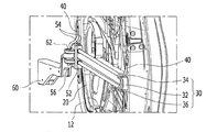
ドアレール30は、ドアインナーパネル12より車室内側に突出するように形成され、ドアの幅方向、すなわち、車両の長手方向に沿って延びるように形成される。車両の長手方向に沿ったドアレール30の前方先端部31及び後方先端部32は、それぞれドアインナーパネル12にマウンティングブラケット40を通じて装着されて支持される。
マウンティングブラケット40は、ほぼ直角プレート形状に形成され、その長手方向に沿った両端部が車両の高さ方向の上部及び下部でドアインナーパネル12に締結される。ドアレール30の前方先端部31と後方先端部32は、それぞれマウンティングブラケット40とドアインナーパネル12との間に挿入されて支持される。
ドアレール30は、車両の長手方向に沿って前後に延びるように形成されて、ドアの高さ方向のほぼ中央部付近に配置されることにより、スライディングドア10の剛性を増大させて、車両の側面衝突に効果的に対応できるので、従来、ドアの側面衝突に対応するために装着されていたインパクトビームなどが不要となる。これにより、スライディングドアの部品数、重量及び原価の節減を図ることができる。
The
The
The
ドアレール30には、スライダ50がドアレール30に沿って移動可能に結合され、スライダ50には、スイングアーム60の一端が相対回転可能にピンにより締結され、スイングアーム60の他端は、図示していない車体にピンにより相対回転可能に締結される。
これにより、スライディングドア10が車体にスイングアーム60を通じて回転可能に支持され、スライダ50に結合されたドアレール30を介して車両の長手方向に沿って前後にスライドして、車体に形成されるドア開口部を開閉する。
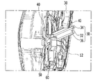
図2及び図3に示す通り、ドアレール30は、ほぼ直角ブロック形状をしたレールボディと、レールボディに一体に形成されて、ドアの高さ方向上部に配置された上部ガイドレール34と、下部に配置された下部ガイドレール36とをそれぞれ含む。
A
As a result, the sliding
As shown in FIGS. 2 and 3, the
上部ガイドレール34と下部ガイドレール36は、それぞれ丸棒形状に形成されてもよく、図4に示すように、剛性を増大させるために補強部材として、例えば、鉄芯38がそれぞれインサートされてもよい。 スライダ50は、上部ガイドレール34と下部ガイドレール36がそれぞれ挿入される2つのスライダブロック52と、2つのスライダブロック52にそれぞれインサートされて、上部ガイドレール34と下部ガイドレール36にそれぞれ接触してローリング移動する複数個のローラ54と、2つのスライダブロック52を連結して固定し、スイングアーム60の一端がピン62により締結される支持ブラケット56とをそれぞれ含む。 上記のように、ドアレール30には、スライダ50をガイドする丸棒形状の2つの上部ガイドレール34及び下部ガイドレール36が備えられて、スライダ50が2つの上部ガイドレール34及び下部ガイドレール36に沿って安定したスライド運動が可能なので、スライディングドアの開閉機能が向上する。
The
図3,4に示す通り、マウンティングブラケット40には、上部ガイドレール34と下部ガイドレール36がそれぞれ挿入されて移動しないように支持される。そして、ほぼ円弧形状の2つの支持溝42と、2つの支持溝42の間に配置されて、レールボディに面着してレールボディが動かないように支持する支持フランジ44と、支持溝42からそれぞれ延びるように形成されて、ドアインナーパネル12に締結される締結フランジ46とをそれぞれ含む。
上記のようなマウンティングブラケット40の支持溝42及び支持フランジ44により、ドアレール30をドアインナーパネル12に装着して支持させることができる。
As shown in FIGS. 3 and 4, the
The
以上、本発明は、好ましい実施例を図によって説明したが、本発明は前述した特定の実施例に限定されるものではなく、本発明が属する技術分野を逸脱しない範囲での全ての変更が含まれる。 The present invention has been described with reference to the preferred embodiments. However, the present invention is not limited to the specific embodiments described above, and includes all modifications within the scope of the technical field to which the present invention belongs. It is.
10 スライディングドア
12 ドアインナーパネル
14 ドアアウターパネル
20 モジュールブラケット
30 ドアレール
31 前方先端部
32 後方先端部
34 上部ガイドレール
36 下部ガイドレール
38 鉄芯
40 マウンティングブラケット
50 スライダ
60 スイングアーム
DESCRIPTION OF
Claims (10)
前記モジュールブラケットと一体に形成されて、車体に連結されたスライダが移動可能に結合されたドアレールと、
を含むことを特徴とする車両用スライディングドアのモジュール構造。 Module bracket for mounting door-related parts,
A door rail formed integrally with the module bracket and movably coupled to a slider coupled to the vehicle body;
A modular structure of a sliding door for a vehicle characterized by comprising:
直角ブロック形状をしたレールボディと、
前記レールボディに一体に形成されて、車両の高さ方向に沿った上部に配置された上部ガイドレールと、
車両の高さ方向に沿った下部に配置された下部ガイドレールと、
をそれぞれ含むことを特徴とする請求項4に記載の車両用スライディングドアのモジュール構造。 The door rail is
A rail body with a right-angle block shape,
An upper guide rail formed integrally with the rail body and disposed at an upper portion along the height direction of the vehicle;
A lower guide rail arranged at the lower part along the height direction of the vehicle,
The module structure of the sliding door for vehicles according to claim 4, characterized in that each of them is included.
前記上部ガイドレールと前記下部ガイドレールがそれぞれ挿入される2つのスライダブロックと、
前記2つのスライダブロックにそれぞれインサートされ、前記上部ガイドレールと前記下部ガイドレールにそれぞれ接触してローリング移動する複数個のローラと、
前記2つのスライダブロックを連結して固定し、前記スイングアームの一端が相対回転可能に締結される支持ブラケットと、
を含むことを特徴とする請求項7に記載の車両用スライディングドアのモジュール構造。 The slider is
Two slider blocks into which the upper guide rail and the lower guide rail are respectively inserted;
A plurality of rollers inserted into the two slider blocks, respectively, in contact with the upper guide rail and the lower guide rail, respectively, and a rolling movement;
A support bracket that connects and fixes the two slider blocks, and one end of the swing arm is fastened to be relatively rotatable;
The module structure of the sliding door for vehicles according to claim 7 characterized by including.
前記上部ガイドレールと前記下部ガイドレールがそれぞれ挿入されて支持される円弧形状の2つの支持溝と、
前記2つの支持溝の間に配置されて、前記レールボディに面着して前記レールボディを支持する支持フランジと、
前記支持溝からそれぞれ延びるように形成されて、前記ドアインナーパネルに締結される締結フランジと、
を含むことを特徴とする請求項9に記載の車両用スライディングドアのモジュール構造。 The mounting bracket is
Two arc-shaped support grooves into which the upper guide rail and the lower guide rail are inserted and supported; and
A support flange disposed between the two support grooves and facing the rail body to support the rail body;
A fastening flange formed to extend from the support groove, and fastened to the door inner panel;
The modular structure of the sliding door for vehicles according to claim 9 characterized by things.
Applications Claiming Priority (2)
| Application Number | Priority Date | Filing Date | Title |
|---|---|---|---|
| KR1020150082007A KR101684539B1 (en) | 2015-06-10 | 2015-06-10 | Sliding door module structure for vehicle |
| KR10-2015-0082007 | 2015-06-10 |
Publications (2)
| Publication Number | Publication Date |
|---|---|
| JP2017001654A true JP2017001654A (en) | 2017-01-05 |
| JP6660704B2 JP6660704B2 (en) | 2020-03-11 |
Family
ID=57395093
Family Applications (1)
| Application Number | Title | Priority Date | Filing Date |
|---|---|---|---|
| JP2015202179A Active JP6660704B2 (en) | 2015-06-10 | 2015-10-13 | Module structure of sliding door for vehicles |
Country Status (5)
| Country | Link |
|---|---|
| US (1) | US9593520B2 (en) |
| JP (1) | JP6660704B2 (en) |
| KR (1) | KR101684539B1 (en) |
| CN (1) | CN106240318B (en) |
| DE (1) | DE102015118047A1 (en) |
Families Citing this family (7)
| Publication number | Priority date | Publication date | Assignee | Title |
|---|---|---|---|---|
| CN108819679A (en) * | 2018-04-12 | 2018-11-16 | 江苏派欧汽车零部件有限公司 | Side-sliding door of automobile upper rail bracket |
| KR20200071952A (en) * | 2018-12-12 | 2020-06-22 | 현대자동차주식회사 | Sliding trim cover structure of opposing sliding doors |
| KR20200085133A (en) * | 2019-01-04 | 2020-07-14 | 현대자동차주식회사 | Stiffness reinforced structure for b-pillarless vehicle with opposed sliding doors |
| KR102621230B1 (en) * | 2019-01-24 | 2024-01-05 | 현대자동차 주식회사 | Door for vehicle |
| KR102644310B1 (en) * | 2019-01-24 | 2024-03-07 | 현대자동차주식회사 | The weather strip structure of vehicle doors |
| US11065945B2 (en) * | 2019-06-05 | 2021-07-20 | Nissan North America, Inc. | Vehicle door structure |
| KR20210074886A (en) * | 2019-12-12 | 2021-06-22 | 현대자동차주식회사 | Structure of x-type guide bar for preventing movement of opposed type sliding doors |
Citations (4)
| Publication number | Priority date | Publication date | Assignee | Title |
|---|---|---|---|---|
| JPS52147825A (en) * | 1976-05-31 | 1977-12-08 | Grossbach Alfred | Slide door for vehicle particularly for automobile |
| JP2008062795A (en) * | 2006-09-07 | 2008-03-21 | Mitsubishi Motors Corp | Slide door structure for vehicle |
| JP2009531229A (en) * | 2006-03-23 | 2009-09-03 | エクソンモービル・ケミカル・パテンツ・インク | Door assembly with core module with integrated reinforced belt line |
| US20130269259A1 (en) * | 2012-04-12 | 2013-10-17 | Dura Global Technologies, Llc | Vehicle sliding door assembly |
Family Cites Families (25)
| Publication number | Priority date | Publication date | Assignee | Title |
|---|---|---|---|---|
| DE2443472A1 (en) * | 1974-09-11 | 1976-03-25 | Lunke & Sohn Gmbh | SLIDING DOORS FOR VEHICLES, IN PARTICULAR MOTOR VEHICLES |
| DE3816175A1 (en) * | 1988-05-11 | 1989-11-23 | Bode & Co Geb | PIVOT SLIDING DOOR FOR A VEHICLE, ESPECIALLY A MOTOR VEHICLE |
| JPH0518927U (en) | 1991-08-22 | 1993-03-09 | 三菱自動車工業株式会社 | Rail cover ring mechanism for sliding doors |
| US6183039B1 (en) * | 1999-02-05 | 2001-02-06 | Delphi Technologies, Inc. | Pivot and slide door system |
| US6435600B1 (en) * | 1999-12-21 | 2002-08-20 | Daimlerchrysler Corporation | Method for operating a vehicle power sliding door |
| JP4474739B2 (en) | 2000-05-31 | 2010-06-09 | マツダ株式会社 | Vehicle side door structure |
| US6793268B1 (en) * | 2003-05-12 | 2004-09-21 | Daimlerchrysler Corporation | Gliding door assembly for a motor vehicle |
| JP3889419B2 (en) * | 2004-08-30 | 2007-03-07 | 本田技研工業株式会社 | Sliding door device for vehicle |
| DE102005034346A1 (en) * | 2005-05-09 | 2006-11-23 | Dura Automotive Plettenberg Entwicklungs- Und Vertriebs Gmbh | Sliding door for a motor vehicle |
| JP5040512B2 (en) * | 2006-10-27 | 2012-10-03 | 日産自動車株式会社 | Car sliding door structure |
| DE102007006360A1 (en) * | 2007-02-08 | 2008-08-21 | Dura Automotive Body & Glass Systems Gmbh | Sliding door for a motor vehicle |
| US7798557B2 (en) * | 2007-08-20 | 2010-09-21 | Ford Global Technologies, Llc | Vehicle unguided four-bar rear door articulating and sliding mechanism |
| US7950719B2 (en) * | 2007-09-14 | 2011-05-31 | Ford Global Technologies, Llc | Vehicle dual hinge rear door articulating and sliding system |
| JP2009127290A (en) * | 2007-11-22 | 2009-06-11 | Aisin Seiki Co Ltd | Door opening/closing device for vehicle |
| US7887118B2 (en) * | 2008-11-21 | 2011-02-15 | Ford Global Technologies, Llc | Simultaneous movement system for a vehicle door |
| US7963587B2 (en) * | 2009-05-12 | 2011-06-21 | Honda Motor Company, Ltd. | Attachments to sliding doors and vehicles including same |
| KR101074174B1 (en) | 2009-08-28 | 2011-10-14 | 정은주 | An automatic opening-shutting equipment for car door |
| JP6004163B2 (en) * | 2012-06-08 | 2016-10-05 | スズキ株式会社 | Sliding door structure |
| KR101438961B1 (en) * | 2012-12-24 | 2014-09-11 | 현대자동차주식회사 | Sliding Door |
| US9731581B2 (en) * | 2013-01-29 | 2017-08-15 | Magna Closures Inc. | Vehicle door and door module with multi-portion door carrier |
| KR101534729B1 (en) * | 2013-12-17 | 2015-07-07 | 현대자동차 주식회사 | Rail locking device |
| KR101542981B1 (en) * | 2013-12-27 | 2015-08-07 | 현대자동차 주식회사 | Front door device of vehicle |
| KR101542980B1 (en) * | 2013-12-27 | 2015-08-07 | 현대자동차 주식회사 | Rear door device of vehicle |
| KR102109937B1 (en) | 2014-01-07 | 2020-05-12 | 삼성전자주식회사 | Method and device for unlocking |
| KR101610157B1 (en) * | 2014-11-06 | 2016-04-08 | 현대자동차 주식회사 | Slider device for vehicle door |
-
2015
- 2015-06-10 KR KR1020150082007A patent/KR101684539B1/en active IP Right Grant
- 2015-10-05 US US14/875,509 patent/US9593520B2/en active Active
- 2015-10-13 JP JP2015202179A patent/JP6660704B2/en active Active
- 2015-10-22 DE DE102015118047.2A patent/DE102015118047A1/en active Pending
- 2015-11-03 CN CN201510738307.6A patent/CN106240318B/en active Active
Patent Citations (4)
| Publication number | Priority date | Publication date | Assignee | Title |
|---|---|---|---|---|
| JPS52147825A (en) * | 1976-05-31 | 1977-12-08 | Grossbach Alfred | Slide door for vehicle particularly for automobile |
| JP2009531229A (en) * | 2006-03-23 | 2009-09-03 | エクソンモービル・ケミカル・パテンツ・インク | Door assembly with core module with integrated reinforced belt line |
| JP2008062795A (en) * | 2006-09-07 | 2008-03-21 | Mitsubishi Motors Corp | Slide door structure for vehicle |
| US20130269259A1 (en) * | 2012-04-12 | 2013-10-17 | Dura Global Technologies, Llc | Vehicle sliding door assembly |
Also Published As
| Publication number | Publication date |
|---|---|
| CN106240318A (en) | 2016-12-21 |
| KR101684539B1 (en) | 2016-12-08 |
| CN106240318B (en) | 2020-11-13 |
| US9593520B2 (en) | 2017-03-14 |
| JP6660704B2 (en) | 2020-03-11 |
| DE102015118047A1 (en) | 2016-12-15 |
| US20160362923A1 (en) | 2016-12-15 |
Similar Documents
| Publication | Publication Date | Title |
|---|---|---|
| JP6660704B2 (en) | Module structure of sliding door for vehicles | |
| JP4593112B2 (en) | Swing / sliding door | |
| US11384580B2 (en) | Dual lower rail structure for opposite sliding doors | |
| US10518616B2 (en) | Sliding and pivoting door combination assembly for a vehicle | |
| CN102616118B (en) | Vehicle including decoration panel of joint connection opposing hinged doors | |
| US20140075843A1 (en) | Vehicle door structure | |
| JP2017534345A (en) | Furniture article having sliding door mechanism | |
| JP2016084078A (en) | Vehicle door structure | |
| US10053900B2 (en) | Center track design for a sliding door | |
| CN210554102U (en) | Sliding vehicle door and vehicle | |
| CN204383140U (en) | Vehicle slide | |
| CN116084790A (en) | Hinge structure, electric sliding door driving mechanism, vehicle body and automobile | |
| JP2008162382A (en) | Slide door device | |
| US10752098B2 (en) | Lifting guide mechanism for sunroof device | |
| KR20210074886A (en) | Structure of x-type guide bar for preventing movement of opposed type sliding doors | |
| JP2020176414A (en) | Opening/closing device for vehicle | |
| KR102665461B1 (en) | Structure for preventing movement of opposed type sliding doors | |
| JPH0716497Y2 (en) | Sliding device for automobile sliding door | |
| KR20210007303A (en) | Lower rail double guide structure of opposed type sliding doors | |
| CN111372821B (en) | Arrangement of a vehicle, electrical connection device and vehicle equipped with such a device | |
| JP2017100585A (en) | Sun visor device for vehicle | |
| KR101393867B1 (en) | Apparatus for opening and closing of covering shelf for vehicles | |
| JP2004189167A (en) | Body structure for vehicle | |
| JP2010137798A (en) | Console box structure | |
| JP2006070596A (en) | Opening and closing device of sliding door for vehicle |
Legal Events
| Date | Code | Title | Description |
|---|---|---|---|
| A621 | Written request for application examination |
Free format text: JAPANESE INTERMEDIATE CODE: A621 Effective date: 20180912 |
|
| A977 | Report on retrieval |
Free format text: JAPANESE INTERMEDIATE CODE: A971007 Effective date: 20190722 |
|
| A131 | Notification of reasons for refusal |
Free format text: JAPANESE INTERMEDIATE CODE: A131 Effective date: 20190730 |
|
| A521 | Request for written amendment filed |
Free format text: JAPANESE INTERMEDIATE CODE: A523 Effective date: 20191029 |
|
| TRDD | Decision of grant or rejection written | ||
| A01 | Written decision to grant a patent or to grant a registration (utility model) |
Free format text: JAPANESE INTERMEDIATE CODE: A01 Effective date: 20200204 |
|
| A61 | First payment of annual fees (during grant procedure) |
Free format text: JAPANESE INTERMEDIATE CODE: A61 Effective date: 20200210 |
|
| R150 | Certificate of patent or registration of utility model |
Ref document number: 6660704 Country of ref document: JP Free format text: JAPANESE INTERMEDIATE CODE: R150 |
|
| R250 | Receipt of annual fees |
Free format text: JAPANESE INTERMEDIATE CODE: R250 |
|
| R250 | Receipt of annual fees |
Free format text: JAPANESE INTERMEDIATE CODE: R250 |