JP4593112B2 - Swing / sliding door - Google Patents
Swing / sliding door Download PDFInfo
- Publication number
- JP4593112B2 JP4593112B2 JP2003561905A JP2003561905A JP4593112B2 JP 4593112 B2 JP4593112 B2 JP 4593112B2 JP 2003561905 A JP2003561905 A JP 2003561905A JP 2003561905 A JP2003561905 A JP 2003561905A JP 4593112 B2 JP4593112 B2 JP 4593112B2
- Authority
- JP
- Japan
- Prior art keywords
- door
- axis
- guide
- door according
- control lever
- Prior art date
- Legal status (The legal status is an assumption and is not a legal conclusion. Google has not performed a legal analysis and makes no representation as to the accuracy of the status listed.)
- Expired - Lifetime
Links
- 230000000452 restraining effect Effects 0.000 claims description 4
- 238000006073 displacement reaction Methods 0.000 abstract description 2
- 230000001681 protective effect Effects 0.000 description 2
- 230000000694 effects Effects 0.000 description 1
- 239000011521 glass Substances 0.000 description 1
Images


Classifications
-
- B—PERFORMING OPERATIONS; TRANSPORTING
- B60—VEHICLES IN GENERAL
- B60J—WINDOWS, WINDSCREENS, NON-FIXED ROOFS, DOORS, OR SIMILAR DEVICES FOR VEHICLES; REMOVABLE EXTERNAL PROTECTIVE COVERINGS SPECIALLY ADAPTED FOR VEHICLES
- B60J5/00—Doors
- B60J5/04—Doors arranged at the vehicle sides
- B60J5/06—Doors arranged at the vehicle sides slidable; foldable
- B60J5/062—Doors arranged at the vehicle sides slidable; foldable for utility vehicles or public transport
-
- E—FIXED CONSTRUCTIONS
- E05—LOCKS; KEYS; WINDOW OR DOOR FITTINGS; SAFES
- E05D—HINGES OR SUSPENSION DEVICES FOR DOORS, WINDOWS OR WINGS
- E05D15/00—Suspension arrangements for wings
- E05D15/28—Suspension arrangements for wings supported on arms movable in horizontal plane
- E05D15/30—Suspension arrangements for wings supported on arms movable in horizontal plane with pivoted arms and sliding guides
-
- E—FIXED CONSTRUCTIONS
- E05—LOCKS; KEYS; WINDOW OR DOOR FITTINGS; SAFES
- E05F—DEVICES FOR MOVING WINGS INTO OPEN OR CLOSED POSITION; CHECKS FOR WINGS; WING FITTINGS NOT OTHERWISE PROVIDED FOR, CONCERNED WITH THE FUNCTIONING OF THE WING
- E05F15/00—Power-operated mechanisms for wings
- E05F15/60—Power-operated mechanisms for wings using electrical actuators
- E05F15/603—Power-operated mechanisms for wings using electrical actuators using rotary electromotors
- E05F15/611—Power-operated mechanisms for wings using electrical actuators using rotary electromotors for swinging wings
- E05F15/63—Power-operated mechanisms for wings using electrical actuators using rotary electromotors for swinging wings operated by swinging arms
-
- E—FIXED CONSTRUCTIONS
- E05—LOCKS; KEYS; WINDOW OR DOOR FITTINGS; SAFES
- E05D—HINGES OR SUSPENSION DEVICES FOR DOORS, WINDOWS OR WINGS
- E05D15/00—Suspension arrangements for wings
- E05D15/06—Suspension arrangements for wings for wings sliding horizontally more or less in their own plane
- E05D15/0621—Details, e.g. suspension or supporting guides
- E05D15/0626—Details, e.g. suspension or supporting guides for wings suspended at the top
- E05D15/0647—Details, e.g. suspension or supporting guides for wings suspended at the top on sliding blocks
-
- E—FIXED CONSTRUCTIONS
- E05—LOCKS; KEYS; WINDOW OR DOOR FITTINGS; SAFES
- E05Y—INDEXING SCHEME ASSOCIATED WITH SUBCLASSES E05D AND E05F, RELATING TO CONSTRUCTION ELEMENTS, ELECTRIC CONTROL, POWER SUPPLY, POWER SIGNAL OR TRANSMISSION, USER INTERFACES, MOUNTING OR COUPLING, DETAILS, ACCESSORIES, AUXILIARY OPERATIONS NOT OTHERWISE PROVIDED FOR, APPLICATION THEREOF
- E05Y2900/00—Application of doors, windows, wings or fittings thereof
- E05Y2900/50—Application of doors, windows, wings or fittings thereof for vehicles
- E05Y2900/53—Type of wing
- E05Y2900/531—Doors
Landscapes
- Mechanical Engineering (AREA)
- Engineering & Computer Science (AREA)
- Power-Operated Mechanisms For Wings (AREA)
- Support Devices For Sliding Doors (AREA)
- Hinges (AREA)
- Body Structure For Vehicles (AREA)
- Seal Device For Vehicle (AREA)
- Lock And Its Accessories (AREA)
- Elevator Door Apparatuses (AREA)
- Glass Compositions (AREA)
- Seats For Vehicles (AREA)
- Polymerisation Methods In General (AREA)
- Liquid Crystal Substances (AREA)
- Closing And Opening Devices For Wings, And Checks For Wings (AREA)
- Harvester Elements (AREA)
- Wing Frames And Configurations (AREA)
Abstract
Description
本発明はドアに関し、より詳しくは車両用ドアに関するが、これに限定されるものではない。 The present invention relates to a door, and more particularly to a vehicle door, but is not limited thereto.
特に、路面走行客車および鉄道客車に乗客が乗り降りできるようにする車両用スライドドアは良く知られている。このようなドアは、開くときに、ドア開口の一側または両側に設けた車両構造体内のキャビティ内に直線的に移動する。また、いわゆるスイングプラグドア(swing plug doors)があり、該ドアは、これを外方にかつドア開口の側方にスイングさせることができるスイング機構に取付けられている。また、或るスイングプラグドアは、該ドアを車両構造体の外面上でスライドできるようにするスライド機構を有している。 In particular, vehicular sliding doors that allow passengers to get on and off road passenger cars and railway passenger cars are well known. When such a door is opened, it moves linearly into a cavity in the vehicle structure provided on one or both sides of the door opening. There are also so-called swing plug doors, which are attached to a swing mechanism that can swing them outward and to the sides of the door opening. Some swing plug doors also have a slide mechanism that allows the door to slide on the outer surface of the vehicle structure.
車両構造体内のキャビティ内にスライドするドアは、ドアを収容するためのドア開口の側方に大きいスペースを必要とする。従ってこのようなドアは、鉄道車両には使用できるが、キャビティのためのスペースをもたない、より小型の車両には不適当である。
スイングプラグドアは、ドアがドア開口の外方に移動された後にその側方変位を増大させるスライド機構を設けない限り、車両構造体を、ドア開口を超えて大きく伸長させる必要はない。しかしながら、スイングプラグドアは、ドアを支持しかつその移動を制御するレバー構造を使用しており、この機構は、ドアが閉じられたときに、しばしば車両の内部に大きく侵入する。従って、このようなシステムは、小型車両で使用するには不適当である。
A door that slides into a cavity in a vehicle structure requires a large space on the side of the door opening for accommodating the door. Such doors can therefore be used for railway vehicles, but are not suitable for smaller vehicles that do not have space for cavities.
As long as the swing plug door is not provided with a slide mechanism that increases the lateral displacement after the door is moved to the outside of the door opening, the vehicle structure does not need to be greatly extended beyond the door opening. However, swing plug doors use a lever structure that supports the door and controls its movement, and this mechanism often penetrates heavily into the interior of the vehicle when the door is closed. Such systems are therefore unsuitable for use in small vehicles.
本発明の目的は、上記の従来技術の欠点を解消し、小型車両での使用に適したスイング/スライドドアを提供することにある。 An object of the present invention is to provide a swing / sliding door suitable for use in a small vehicle by eliminating the above-mentioned drawbacks of the prior art.
本発明によれば、構造体のドア開口に対して開位置と閉位置との間で変位できるように構造体に取付けられるドアにおいて、構造体に固定された軸線の回りの弧状移動を行なわせるように、開位置に向かう移動に対してドアの前縁部を拘束する第一ガイド手段と、ドア開口の平面に対してほぼ平行な直線的移動を行なわせるように、ドアの後縁部を拘束する第二ガイド手段とにより構造体に連結されることを特徴とするドアが提供される。 According to the present invention, in the door attached to the structure so that it can be displaced between the open position and the closed position with respect to the door opening of the structure, the arc movement around the axis fixed to the structure is performed. The first guide means for restraining the front edge portion of the door with respect to the movement toward the open position, and the rear edge portion of the door so as to perform a linear movement substantially parallel to the plane of the door opening A door is provided which is connected to the structure by a second guide means for restraining.
本願明細書において、ドアの「前(leading)」縁部および「後(trailing)」縁部とは、ドアを開くときの移動方向を基準としている。
第一ガイド手段にはドア制御レバーを設けることができ、該ドア制御レバーは、その一端が、構造体に固定された一軸線の回りで枢動でき、その他端は、ドアの前縁部に隣接してドアに枢着される。レバーが枢動する軸線は、ほぼ垂直にすることができる。
開位置と閉位置との間でドアを移動させるための駆動手段を設けることができる。この駆動手段は、例えば、前記軸線から突出しかつドア制御レバーに固定されたレバーまたは歯車のような駆動要素に作用することによりドア制御レバーを回転させるように取付けることができる。
ドアの安定性を高めるため、2つのドア制御レバーを設けることができる。これらのドア制御レバーは、該ドア制御レバーが枢動する軸線を形成する共通軸に固定できる。ドア制御レバーは、共通軸とドアへの枢着点との間の長さを互いに等しくすることができる。
In this specification, the “leading” edge and the “trailing” edge of the door are based on the direction of movement when the door is opened.
The first guide means can be provided with a door control lever, one end of which can be pivoted about one axis fixed to the structure, and the other end is at the front edge of the door. Adjacent to the door. The axis about which the lever pivots can be substantially vertical.
Drive means for moving the door between the open position and the closed position can be provided. The drive means can be mounted to rotate the door control lever by acting on a drive element such as a lever or gear that protrudes from the axis and is fixed to the door control lever, for example.
To increase door stability, two door control levers can be provided. These door control levers can be fixed to a common shaft that forms an axis about which the door control lever pivots. The door control levers can be equal in length between the common shaft and the pivot point to the door.
第二ガイド手段には、ドアの後縁部に隣接して取付けられかつ構造体に固定された例えばレールの形態をなすガイドトラックに沿ってスライドできるガイド要素を設けることができる。ガイドトラックは、第一ガイド手段により制御される弧状移動の軸線に対して垂直な平面内に設けることができる。かくして、前記軸線がほぼ垂直である場合には、ガイドトラックはほぼ水平でかつドア開口の平面に平行になる。
第二ガイド手段は、例えばドアの上端部および下端部に隣接して配置された2つのガイドトラックで構成できる。ガイドトラックは、弧状移動の軸線に対して傾斜している共通平面内に配置できる。
The second guide means can be provided with a guide element which can be slid along a guide track, for example in the form of a rail, which is mounted adjacent to the rear edge of the door and is fixed to the structure. The guide track can be provided in a plane perpendicular to the axis of arcuate movement controlled by the first guide means. Thus, when the axis is substantially vertical, the guide track is substantially horizontal and parallel to the plane of the door opening.
The second guide means can be composed of, for example, two guide tracks arranged adjacent to the upper and lower ends of the door. The guide tracks can be arranged in a common plane that is inclined with respect to the axis of arcuate movement.
ドアは、該ドアの異なる部分が異なる平面内に位置するように湾曲させるか、他の形状にすることができる。例えば、ドアの上方部分を、ドアの下方部分に対して(構造体の)内方に変位させることができる。例えば、ドアは、ほぼ水平な軸線の回りで湾曲させることができる。このような形状にすれば、ドアは、開位置と閉位置との間で移動するときに第一および第二ガイド手段の作用を受けて撓むことができる。 The door can be curved or otherwise shaped so that different portions of the door are located in different planes. For example, the upper part of the door can be displaced inward (of the structure) relative to the lower part of the door. For example, the door can be curved about a substantially horizontal axis. With such a shape, the door can be bent under the action of the first and second guide means when moving between the open position and the closed position.
好ましい実施形態では、前記構造体は車両ボディであり、ドアは、車両の内部に乗客軸線を形成すべく設けられる。車両ボディには内板および外板を設けることができ、この場合には、弧状移動の軸線は内板と外板との間で延び、駆動手段も内板と外板との間に設けることができる。ドアが1つ以上のドア制御レバーにより制御される場合に、これらのレバーの少なくとも1つは、ドアの開位置において、外板の開口を通って突出するように構成できる。
同様に、第一ガイドが上方および下方のガイドトラックを有する場合には、上方ガイドトラックを外板のチャネル内に配置できる。下方ガイドトラックは車両のフロアの下に配置できる。
In a preferred embodiment, the structure is a vehicle body and the door is provided to form a passenger axis within the vehicle. The vehicle body can be provided with an inner plate and an outer plate. In this case, the axis of arc movement extends between the inner plate and the outer plate, and the driving means is also provided between the inner plate and the outer plate. Can do. When the door is controlled by one or more door control levers, at least one of these levers can be configured to protrude through the opening in the skin in the open position of the door.
Similarly, if the first guide has upper and lower guide tracks, the upper guide track can be placed in the channel of the skin. The lower guide track can be placed under the vehicle floor.
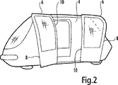
図1および図2に示す車両は、都市交通システムに使用するためのものである。このようなシステムでは、車両の全席を乗客が使用できる。車両には運転者はおらず、車両は適当なガイド手段が設けられた専用トラック上を循環する。
車両は、ドア開口4(好ましくは車両の各側に1つ設けられている)を備えた主車両構造体2を有している。各ドア開口4は1対のドア6により閉じられ、該ドア6は、図2に示すように、車両内部へのアクセスが行なえるように開くことができる。図2に示すように、開位置において、各ドアの前縁部8(開位置に向かうドアの移動方向で見て前縁部)はドア開口4の外方に変位され、一方、後縁部10はほぼドア開口4の平面内に留まる。かくして、ドア開口6は、外方に大きくスイング移動することなく開くことができる。自動操作型ドアではこのようなスイング移動は好ましくない。なぜならば、スイング移動によって、ドアが、車両の側方で待機する乗客または物体に当ることがあるからである。また、ドアが開いたときのドアの傾斜位置により、乗客を車両内に向かわせる導入効果(funneling effect)が生じる。
The vehicle shown in FIGS. 1 and 2 is for use in an urban transportation system. In such a system, passengers can use all seats of the vehicle. There is no driver in the vehicle, and the vehicle circulates on a dedicated truck provided with appropriate guide means.
The vehicle has a
図3に示すように、ドア6は、その前縁部8が第一ガイド手段12により支持されかつその後縁部10が第二ガイド手段14により支持されている。第一ガイド手段12は直立軸16を有し、該直立軸16は、車両構造体2に対して固定されたベアリング(図示せず)により上部および下部が支持されている。軸16には、この上端部および下端部に隣接した位置で、ドア制御レバー18、20が固定されている。両制御レバー18、20は、互いに平行に延びておりかつ互いに実質的に同じ長さを有している。各レバー18、20は、前縁部8に近い位置で、自動調心ベアリング22を介してドア6に連結されている。
レバー24の形態をなす駆動要素が、軸16の下端部に固定されている。軸16とは反対側の駆動レバー24の端部は、モータに連結されている。
As shown in FIG. 3, the door 6 has a front edge portion 8 supported by the first guide means 12 and a
A drive element in the form of a lever 24 is fixed to the lower end of the
第二ガイド手段14はレール26、28の形態をなすガイドトラックをを有し、レール26、28はドア開口4のそれぞれ上部および下部において車両構造体2に固定される。ドア6の後縁部10に隣接して、ドア6の上縁部および下縁部の近くにはそれぞれスライダ30、32が取付けられている。
レール26、28は、車両の長手方向軸線に対して平行またはほぼ平行に延びかつドア開口の平面内または該平面の近くに位置する。かくして、レール26、28は互いに平行またはほぼ平行でありかつ軸16の軸線に対して傾斜した共通平面内または該平面の近くに位置する。これは、ドア開口6が特にその上端部で湾曲しているため、レール26、28を含む垂直平面が互いに間隔を隔てており、レール26を含む平面が車両のインボード方向に変位していることによる。
レール26はドアの所要移動を可能にするため僅かに湾曲させることができ、このため、本願明細書で使用する「ほぼ平行」という表現には、真に平行な形態からの偏寄がこのような曲りから生じる可能性を含むことに留意されたい。
The second guide means 14 has a guide track in the form of
The
The
ドア6の閉位置および開位置は、それぞれ実線6および破線6′で示されている。駆動レバー24に取付けられたモータの作用により軸16が回転されると、ドア制御レバー18、20が外方にスイングしてドアの前縁部8を、弧状経路を通して移動させる。これにより、前縁部8が、ドア開口4の平面から外れかつドア開口から長手方向に遠ざかる。しかしながら、ドアの後縁部10はレール26により案内されるため、ドア開口4の平面から外れて移動することはない。
レール26はレール28よりも車両の中心平面の近くに位置しているので、レール26、28は軸16の軸線に対して平行な平面内には位置しない。従って、ドア6が開位置と閉位置との間で移動するときに、ドア6は撓むことになる。従って、ドアは充分な可撓性をもつように構成し、これにより構成部品に過度の応力を生じさせることなく撓み得るようにする必要がある。いずれかの特定用途においてこのような撓みが好ましくない場合には、ドア6の後縁部10の制御は、単一のレール26または28および単一のスライダ30または32のみで達成することができる。
The closed position and the open position of the door 6 are indicated by a solid line 6 and a broken line 6 ', respectively. When the
Since the
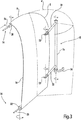
図4および図5には、ドア6の後縁部10の上端部の構造がより詳細に示されている。車両構造体2は、ルーフパネルを備えた外板34を有している。ルーフパネル34は、ドア開口4の境界を定める縁部が延長されており、シール38に終端するチャネル36を形成している。
ドア6はドアフレーム40を有し、該ドアフレーム40には、窓を形成するガラス層42が接合される。ドアフレーム40には、ねじ46によりスライドマウント44が固定されている。スライドマウント44はスピゴット48を有し、該スピゴット48には、ブシュ50を介してスライダ30が枢着されている。スライダ30は、スナップリング52によりスピゴット48上に保持されている。スライダ30内には、レール26と係合する他のブシュ54が保持されている。
4 and 5 show the structure of the upper end portion of the
The door 6 has a
図6および図7には、ドア6の後縁部10の下端部側のレール28およびスライダ32の構造がより詳細に示されている。図6および図7に示すように、車両構造体2はフレーム56を有し、該フレーム56には保護ビーム58が固定されている。フレーム56によりフロアパネル60が支持されている。ドア6には、スピゴット64を備えたスライダマウント62がねじ66により固定されている。スピゴット64には、ブシュ68を介してスライダ32が取付けられている。スライダ32内には、レール28と係合するブシュ70が収容されている。
レール26、28は、図示しない手段により車両構造体2に固定される。
6 and 7 show the structure of the
The
図4〜図7から理解されようが、両レール26、28およびこれらに関連するスライダ30、32は、車両の客室の外部で作動する。チャネル36は、上方レール36およびスライダ30を遮蔽して車両内の乗客に接触しないようにし、一方、フロアボード60および保護ビーム58も同様に下方レール28および下方スライダ32を遮蔽する。
図4から理解されようが、車両構造体2は外板34を有している。図示しないが、外板34の内方には内板も設けられ、乗客室を形成している。内板と外板との間には軸16が配置され、駆動レバー24およびこれに連結されたモータも同様にこれらの両板の間に配置されている。外板34には例えばスロットの形態の開口が設けられており、ドア6が開かれるときに前記スロットに沿って各ドア制御レバー18、20が移動する。かくして、軸16に関連する機構は、客室から遮蔽されている。
As can be seen from FIGS. 4-7, both
As can be understood from FIG. 4, the
2 車両構造体
4 ドア開口
6 ドア
12 第一ガイド手段
14 第二ガイド手段
16 直立軸
18、20 ドア制御レバー
24 駆動レバー
26、28 レール(ガイドトラック)
30、32 スライダ
2 Vehicle structure 4 Door opening 6 Door 12 First guide means 14 Second guide means 16
30, 32 slider
Claims (19)
Applications Claiming Priority (2)
| Application Number | Priority Date | Filing Date | Title |
|---|---|---|---|
| GBGB0201092.4A GB0201092D0 (en) | 2002-01-17 | 2002-01-17 | A door |
| PCT/GB2003/000144 WO2003061999A1 (en) | 2002-01-17 | 2003-01-16 | A swing and slide door |
Publications (3)
| Publication Number | Publication Date |
|---|---|
| JP2005515329A JP2005515329A (en) | 2005-05-26 |
| JP2005515329A5 JP2005515329A5 (en) | 2010-09-09 |
| JP4593112B2 true JP4593112B2 (en) | 2010-12-08 |
Family
ID=9929285
Family Applications (1)
| Application Number | Title | Priority Date | Filing Date |
|---|---|---|---|
| JP2003561905A Expired - Lifetime JP4593112B2 (en) | 2002-01-17 | 2003-01-16 | Swing / sliding door |
Country Status (12)
| Country | Link |
|---|---|
| US (1) | US7364219B2 (en) |
| EP (1) | EP1467880B1 (en) |
| JP (1) | JP4593112B2 (en) |
| KR (1) | KR100940896B1 (en) |
| AT (1) | ATE430052T1 (en) |
| CA (1) | CA2473704C (en) |
| DE (1) | DE60327419D1 (en) |
| DK (1) | DK1467880T3 (en) |
| ES (1) | ES2326117T3 (en) |
| GB (1) | GB0201092D0 (en) |
| PT (1) | PT1467880E (en) |
| WO (1) | WO2003061999A1 (en) |
Families Citing this family (28)
| Publication number | Priority date | Publication date | Assignee | Title |
|---|---|---|---|---|
| FR2866916B1 (en) * | 2004-03-01 | 2007-09-07 | France Design | MOTOR VEHICLE COMPRISING A GUIDED LATERAL DOOR IN TRANSLATION AND ROTATION |
| FR2869633B1 (en) * | 2004-04-30 | 2008-02-22 | Renault Sas | DEVICE FOR MOUNTING A MOTOR VEHICLE DOOR. |
| US20080100394A1 (en) * | 2004-06-30 | 2008-05-01 | Emag Technologies, Inc. | Microstrip to Coplanar Waveguide Transition |
| FR2874568B1 (en) * | 2004-08-27 | 2006-11-03 | Alstom Transport Sa | VEHICLE DOOR EQUIPPED WITH JOINT |
| DE102006006288A1 (en) * | 2006-02-10 | 2007-08-23 | Hte Ag The High Throughput Experimentation Company | Dosing station and method for dosing highly viscous liquids |
| US7798557B2 (en) | 2007-08-20 | 2010-09-21 | Ford Global Technologies, Llc | Vehicle unguided four-bar rear door articulating and sliding mechanism |
| US7980621B2 (en) * | 2007-09-14 | 2011-07-19 | Ford Global Technologies, Llc | Vehicle rear door articulating mechanism |
| US7950109B2 (en) * | 2007-09-14 | 2011-05-31 | Ford Global Technologies, Llc | Vehicle 180 degree rear door articulating mechanism |
| US7950719B2 (en) * | 2007-09-14 | 2011-05-31 | Ford Global Technologies, Llc | Vehicle dual hinge rear door articulating and sliding system |
| US7887118B2 (en) * | 2008-11-21 | 2011-02-15 | Ford Global Technologies, Llc | Simultaneous movement system for a vehicle door |
| US7856759B2 (en) | 2008-12-18 | 2010-12-28 | Ford Global Technologies, Llc | Dual action power drive unit for a vehicle door |
| US7918492B2 (en) * | 2009-01-05 | 2011-04-05 | Ford Global Technologies, Llc | Vehicle door belt and cam articulating mechanism |
| US20100295337A1 (en) * | 2009-05-22 | 2010-11-25 | Adrian Elliott | Simultaneous single rail movement system for a vehicle door ii |
| US7896425B2 (en) * | 2009-07-15 | 2011-03-01 | Ford Global Technologies, Llc | Simultaneous movement system for a vehicle door II |
| US8919860B2 (en) * | 2011-08-22 | 2014-12-30 | Honda Motor Co., Ltd. | Slide door movement system without center rail |
| CN103924900B (en) * | 2014-04-09 | 2015-12-30 | 江苏大学 | One draws movement mechanism apparatus based on virtual line moving guide rail stopping sliding door plug |
| US9428949B2 (en) * | 2014-07-10 | 2016-08-30 | Paul Hirneise | Double door system for personal vehicles |
| US9079478B1 (en) * | 2014-07-10 | 2015-07-14 | Paul Hirneise | Double door for personal vehicle |
| US9789922B2 (en) | 2014-12-18 | 2017-10-17 | The Braun Corporation | Modified door opening of a motorized vehicle for accommodating a ramp system and method thereof |
| US9605465B2 (en) * | 2015-02-17 | 2017-03-28 | The Braun Corporation | Automatic door operation |
| US10562722B2 (en) | 2016-09-29 | 2020-02-18 | The Braun Corporation | Modified K-member of suspension assembly and method of modification thereof |
| US10676974B2 (en) | 2016-11-02 | 2020-06-09 | The Braun Corporation | Overtravel hinge |
| US10532776B2 (en) | 2016-11-07 | 2020-01-14 | The Braun Corporation | Suspension assembly for a rear entry vehicle |
| DE102017113779A1 (en) * | 2017-06-21 | 2018-12-27 | Man Truck & Bus Ag | Door leaf with upper, reduced part area for an exterior mirror construction |
| GB2565822B (en) * | 2017-08-24 | 2020-04-29 | Ford Global Tech Llc | Vehicle door system |
| US10876341B2 (en) * | 2018-07-24 | 2020-12-29 | Brose Fahrzeugteile Gmbh & Co. Kommanditgesellschaft, Bamberg | Door drive system |
| KR102630375B1 (en) * | 2019-01-04 | 2024-01-30 | 현대자동차주식회사 | The weather strip structure of vehicle equipped with opposing sliding doors |
| JP7192762B2 (en) * | 2019-12-26 | 2022-12-20 | トヨタ自動車株式会社 | Handrail for getting on and off |
Family Cites Families (14)
| Publication number | Priority date | Publication date | Assignee | Title |
|---|---|---|---|---|
| JPH0229181Y2 (en) * | 1981-03-13 | 1990-08-06 | ||
| JPS58156668A (en) * | 1982-03-12 | 1983-09-17 | トヨタ車体株式会社 | Slide door opening and closing apparatus |
| US4631894A (en) * | 1982-04-26 | 1986-12-30 | Acme General Corporation | Hardware for panel doors |
| FR2621879A1 (en) * | 1987-10-14 | 1989-04-21 | Faiveley Ets | LOUVOYANTE DOOR FOR QUICK TRAIN |
| JPH0710063U (en) * | 1993-07-22 | 1995-02-10 | 油谷重工株式会社 | Door opening and closing device for construction machinery |
| US5398988A (en) * | 1993-11-22 | 1995-03-21 | Chrysler Corporation | Vehicle door assembly |
| US6565144B1 (en) * | 1999-04-01 | 2003-05-20 | Alfa Leisure, Inc. | Recreational vehicles with walk-in closet |
| US6036257A (en) * | 1999-06-02 | 2000-03-14 | General Motors Corporation | Articulating lower roller assembly for sliding vehicle door |
| JP2001107393A (en) * | 1999-10-07 | 2001-04-17 | Press Kogyo Co Ltd | Front link type slide door device for construction machine |
| FR2804380B1 (en) * | 2000-02-02 | 2002-04-05 | Renault | HINGE SYSTEM FOR A MOTOR VEHICLE TRUNK DOOR COMPRISING AN ARTICULATED ARM AND A SLIDING ARM |
| JP2003314135A (en) * | 2002-04-26 | 2003-11-06 | Sumitomo Heavy Industries Construction Crane Co Ltd | Door opening/closing mechanism |
| US20030218358A1 (en) * | 2002-05-24 | 2003-11-27 | Seonho Hahn | Dual mode vehicle side door |
| DE10392811B4 (en) * | 2002-06-11 | 2018-10-31 | Intier Automotive Closures Inc. | Vehicle sliding door with swivel arm |
| US6948765B2 (en) * | 2003-12-23 | 2005-09-27 | Westinghouse Air Brake Technologies Corporation | Lock mechanism for a rotary door operator |
-
2002
- 2002-01-17 GB GBGB0201092.4A patent/GB0201092D0/en not_active Ceased
-
2003
- 2003-01-16 DK DK03700874T patent/DK1467880T3/en active
- 2003-01-16 JP JP2003561905A patent/JP4593112B2/en not_active Expired - Lifetime
- 2003-01-16 DE DE60327419T patent/DE60327419D1/en not_active Expired - Lifetime
- 2003-01-16 CA CA2473704A patent/CA2473704C/en not_active Expired - Lifetime
- 2003-01-16 WO PCT/GB2003/000144 patent/WO2003061999A1/en active Application Filing
- 2003-01-16 US US10/501,535 patent/US7364219B2/en not_active Expired - Lifetime
- 2003-01-16 ES ES03700874T patent/ES2326117T3/en not_active Expired - Lifetime
- 2003-01-16 AT AT03700874T patent/ATE430052T1/en active
- 2003-01-16 PT PT03700874T patent/PT1467880E/en unknown
- 2003-01-16 EP EP03700874A patent/EP1467880B1/en not_active Expired - Lifetime
- 2003-01-16 KR KR1020047010980A patent/KR100940896B1/en active IP Right Grant
Also Published As
| Publication number | Publication date |
|---|---|
| EP1467880B1 (en) | 2009-04-29 |
| ATE430052T1 (en) | 2009-05-15 |
| JP2005515329A (en) | 2005-05-26 |
| US7364219B2 (en) | 2008-04-29 |
| EP1467880A1 (en) | 2004-10-20 |
| CA2473704C (en) | 2010-07-20 |
| KR20040101998A (en) | 2004-12-03 |
| GB0201092D0 (en) | 2002-03-06 |
| KR100940896B1 (en) | 2010-02-09 |
| CA2473704A1 (en) | 2003-07-31 |
| PT1467880E (en) | 2009-06-04 |
| DK1467880T3 (en) | 2009-07-20 |
| US20050116496A1 (en) | 2005-06-02 |
| WO2003061999A1 (en) | 2003-07-31 |
| ES2326117T3 (en) | 2009-10-01 |
| DE60327419D1 (en) | 2009-06-10 |
Similar Documents
| Publication | Publication Date | Title |
|---|---|---|
| JP4593112B2 (en) | Swing / sliding door | |
| US6860549B2 (en) | Retractable roof panel | |
| US20180326821A1 (en) | Drive system for a movable roof part of a spoiler roof module of a motor vehicle | |
| US7392618B2 (en) | Door for vehicle having a door glass with projecting portions | |
| US20180326822A1 (en) | Drive system for a movable roof part of a spoiler roof module of a motor vehicle | |
| JPS5915179A (en) | Slide door apparatus for car | |
| KR101684539B1 (en) | Sliding door module structure for vehicle | |
| JP2003237375A (en) | Cabriolet automobile with foldable hard top | |
| JPS6229413A (en) | Sliding door type car door mechanism | |
| US6830290B2 (en) | Motor vehicle with a vehicle roof which can be opened | |
| JP2002370538A (en) | Openable vehicle roof | |
| US20230271567A1 (en) | Wiring harness routing structure, link type sliding door, and wiring harness | |
| CN115593197A (en) | Door hinge device for vehicle | |
| US3141664A (en) | Window regulator | |
| US20240157771A1 (en) | Sliding door system for a vehicle | |
| KR20200091673A (en) | Apparatus for supporting a upper part of sliding door of vehicle | |
| JP2024098579A (en) | Sliding door support mechanism | |
| JP4859024B2 (en) | Outslide door device for vehicle | |
| US20240253429A1 (en) | Vehicle door assembly | |
| KR20090063822A (en) | Sun roof for vehicle | |
| CN116357183A (en) | Door hinge device for vehicle | |
| JPS60222320A (en) | Sliding roof structure for vehicles | |
| JPH0215693Y2 (en) | ||
| JP2020189551A (en) | Vehicle side part structure | |
| RU2222438C2 (en) | Pleasure car |
Legal Events
| Date | Code | Title | Description |
|---|---|---|---|
| A621 | Written request for application examination |
Free format text: JAPANESE INTERMEDIATE CODE: A621 Effective date: 20060105 |
|
| A131 | Notification of reasons for refusal |
Free format text: JAPANESE INTERMEDIATE CODE: A131 Effective date: 20090113 |
|
| A601 | Written request for extension of time |
Free format text: JAPANESE INTERMEDIATE CODE: A601 Effective date: 20090413 |
|
| A602 | Written permission of extension of time |
Free format text: JAPANESE INTERMEDIATE CODE: A602 Effective date: 20090420 |
|
| A521 | Request for written amendment filed |
Free format text: JAPANESE INTERMEDIATE CODE: A523 Effective date: 20090713 |
|
| A131 | Notification of reasons for refusal |
Free format text: JAPANESE INTERMEDIATE CODE: A131 Effective date: 20100426 |
|
| A524 | Written submission of copy of amendment under article 19 pct |
Free format text: JAPANESE INTERMEDIATE CODE: A524 Effective date: 20100726 |
|
| TRDD | Decision of grant or rejection written | ||
| A01 | Written decision to grant a patent or to grant a registration (utility model) |
Free format text: JAPANESE INTERMEDIATE CODE: A01 Effective date: 20100816 |
|
| A01 | Written decision to grant a patent or to grant a registration (utility model) |
Free format text: JAPANESE INTERMEDIATE CODE: A01 |
|
| A61 | First payment of annual fees (during grant procedure) |
Free format text: JAPANESE INTERMEDIATE CODE: A61 Effective date: 20100915 |
|
| FPAY | Renewal fee payment (event date is renewal date of database) |
Free format text: PAYMENT UNTIL: 20130924 Year of fee payment: 3 |
|
| R150 | Certificate of patent or registration of utility model |
Ref document number: 4593112 Country of ref document: JP Free format text: JAPANESE INTERMEDIATE CODE: R150 Free format text: JAPANESE INTERMEDIATE CODE: R150 |
|
| S531 | Written request for registration of change of domicile |
Free format text: JAPANESE INTERMEDIATE CODE: R313531 |
|
| S533 | Written request for registration of change of name |
Free format text: JAPANESE INTERMEDIATE CODE: R313533 |
|
| FPAY | Renewal fee payment (event date is renewal date of database) |
Free format text: PAYMENT UNTIL: 20130924 Year of fee payment: 3 |
|
| S111 | Request for change of ownership or part of ownership |
Free format text: JAPANESE INTERMEDIATE CODE: R313113 |
|
| FPAY | Renewal fee payment (event date is renewal date of database) |
Free format text: PAYMENT UNTIL: 20130924 Year of fee payment: 3 |
|
| R350 | Written notification of registration of transfer |
Free format text: JAPANESE INTERMEDIATE CODE: R350 |
|
| R250 | Receipt of annual fees |
Free format text: JAPANESE INTERMEDIATE CODE: R250 |
|
| R250 | Receipt of annual fees |
Free format text: JAPANESE INTERMEDIATE CODE: R250 |
|
| R250 | Receipt of annual fees |
Free format text: JAPANESE INTERMEDIATE CODE: R250 |
|
| R250 | Receipt of annual fees |
Free format text: JAPANESE INTERMEDIATE CODE: R250 |
|
| R250 | Receipt of annual fees |
Free format text: JAPANESE INTERMEDIATE CODE: R250 |
|
| R250 | Receipt of annual fees |
Free format text: JAPANESE INTERMEDIATE CODE: R250 |
|
| R250 | Receipt of annual fees |
Free format text: JAPANESE INTERMEDIATE CODE: R250 |
|
| R250 | Receipt of annual fees |
Free format text: JAPANESE INTERMEDIATE CODE: R250 |
|
| R250 | Receipt of annual fees |
Free format text: JAPANESE INTERMEDIATE CODE: R250 |
|
| R250 | Receipt of annual fees |
Free format text: JAPANESE INTERMEDIATE CODE: R250 |
|
| EXPY | Cancellation because of completion of term |