JP2016207756A - Stage device and exposure device - Google Patents

Stage device and exposure device Download PDF

Info

Publication number
JP2016207756A
JP2016207756A JP2015085468A JP2015085468A JP2016207756A JP 2016207756 A JP2016207756 A JP 2016207756A JP 2015085468 A JP2015085468 A JP 2015085468A JP 2015085468 A JP2015085468 A JP 2015085468A JP 2016207756 A JP2016207756 A JP 2016207756A
Authority
JP
Japan
Prior art keywords
stage
shuttle
measurement
exposure
wafer
Prior art date
Legal status (The legal status is an assumption and is not a legal conclusion. Google has not performed a legal analysis and makes no representation as to the accuracy of the status listed.)
Pending
Application number
JP2015085468A
Other languages
Japanese (ja)
Inventor
柴崎 祐一
Yuichi Shibazaki
祐一 柴崎
Current Assignee (The listed assignees may be inaccurate. Google has not performed a legal analysis and makes no representation or warranty as to the accuracy of the list.)
Nikon Corp
Original Assignee
Nikon Corp
Priority date (The priority date is an assumption and is not a legal conclusion. Google has not performed a legal analysis and makes no representation as to the accuracy of the date listed.)
Filing date
Publication date
Application filed by Nikon Corp filed Critical Nikon Corp
Priority to JP2015085468A priority Critical patent/JP2016207756A/en
Publication of JP2016207756A publication Critical patent/JP2016207756A/en
Pending legal-status Critical Current

Links

Images

Landscapes

  • Exposure And Positioning Against Photoresist Photosensitive Materials (AREA)
  • Electron Beam Exposure (AREA)
  • Container, Conveyance, Adherence, Positioning, Of Wafer (AREA)

Abstract

PROBLEM TO BE SOLVED: To provide a stage device which does not cause disturbance of a magnetic field.SOLUTION: A stage device includes a platen 321 having a top face parallel with the XY plane, a first stage 322a movable in the X axis direction on the platen 321, a second stage 322b movable for the first stage in 6 degree-of-freedom directions, and movable with a larger stroke in the Y axis direction, out of the 6 degree-of-freedom directions, than other directions, a uniaxial drive mechanism for driving the first stage, a closed magnetic field type and moving magnet type motor that can be driven in 6 degree-of-freedom directions, and a magnetic shield member 328 covering at least the top face and side face of the motor.SELECTED DRAWING: Figure 7

Description

本発明は、ステージ装置及び露光装置に係り、特に荷電粒子線光学系を用いる装置でターゲットの移動装置として好適に用いることができるステージ装置、及びステージ装置によって移動されるターゲットに荷電粒子線を照射する露光装置に関する。   The present invention relates to a stage apparatus and an exposure apparatus, and more particularly to a stage apparatus that can be suitably used as a target moving apparatus in an apparatus that uses a charged particle beam optical system and a target that is moved by the stage apparatus. The present invention relates to an exposure apparatus.

半導体素子等の電子デバイス(マイクロデバイス)を製造するためのリソグラフィ工程で使用され、露光ビームとして遠紫外域から真空紫外域にかけての紫外光を用いる露光装置(以下、紫外光露光装置という)においては、解像度を高めるために、露光波長の短波長化、照明条件の最適化、及び投影光学系の開口数をさらに増大するための液浸法の適用等が行われてきた。   In an exposure apparatus (hereinafter referred to as an ultraviolet light exposure apparatus) that is used in a lithography process for manufacturing electronic devices (microdevices) such as semiconductor elements and uses ultraviolet light from the far ultraviolet region to the vacuum ultraviolet region as an exposure beam. In order to increase the resolution, the exposure wavelength has been shortened, the illumination conditions have been optimized, and the immersion method has been applied to further increase the numerical aperture of the projection optical system.

また、最近では、紫外光露光装置の解像限界よりも微細なピッチの回路パターンを形成するために、ウエハに紫外光露光装置を用いてこの解像限界程度のピッチで、かつ線幅がピッチの1/2とは異なるライン・アンド・スペースパターン(以下、L/Sパターンと表記する)を形成した後、そのL/Sパターンを用いて線幅がピッチの1/2のL/Sパターンを形成するダブルパターニング法が提案されている。   Also, recently, in order to form a circuit pattern with a finer pitch than the resolution limit of an ultraviolet light exposure apparatus, the ultraviolet light exposure apparatus is used on the wafer at a pitch about this resolution limit and the line width is pitch. After forming a line and space pattern (hereinafter referred to as an L / S pattern) different from 1/2 of the above, an L / S pattern having a line width of 1/2 of the pitch using the L / S pattern There has been proposed a double patterning method for forming.

しかしながら、ダブルパターニング法のみでは、紫外光露光装置の解像限界よりも微細な非周期的な部分を含むパターンを形成することは困難であるため、この非周期的な部分の露光に電子ビーム露光装置を用いることが提案されている
(例えば、特許文献1参照)。
However, with the double patterning method alone, it is difficult to form a pattern including a non-periodic portion finer than the resolution limit of an ultraviolet light exposure apparatus. It has been proposed to use an apparatus (see, for example, Patent Document 1).

この電子ビーム露光装置が備えるステージは、真空チャンバ内に設置され、且つ、電子ビームの位置決めに影響を与える磁場変動を引き起こしてはならないという拘束があった。   The stage included in this electron beam exposure apparatus is installed in a vacuum chamber, and there is a constraint that it must not cause magnetic field fluctuations that affect the positioning of the electron beam.

米国特許第7,173,263号明細書US Pat. No. 7,173,263

本発明の第1の態様によれば、所定平面と平行な上面を有するベース部材と、前記ベース部材上で前記所定平面内の第1方向に移動可能な第1ステージと、前記第1ステージに対して6自由度方向に移動可能かつ前記6自由度方向のうち所定平面内で前記第1方向に直交する第2方向には他の方向より大きいストロークで移動可能な第2ステージと、前記第1ステージを駆動する一軸駆動機構と、前記第2ステージを、前記6自由度方向に駆動可能な閉磁界型かつムービングマグネット型のモータと、前記モータの少なくとも上面及び側面を覆う磁気シールド部材と、を備える第1のステージ装置が、提供される。   According to the first aspect of the present invention, a base member having an upper surface parallel to a predetermined plane, a first stage movable on the base member in a first direction within the predetermined plane, and the first stage A second stage movable in a direction of 6 degrees of freedom and movable in a second plane orthogonal to the first direction in a predetermined plane of the 6 degrees of freedom direction with a stroke larger than the other directions; A uniaxial drive mechanism for driving one stage; a closed magnetic field type and moving magnet type motor capable of driving the second stage in the direction of six degrees of freedom; and a magnetic shield member covering at least an upper surface and a side surface of the motor; A first stage apparatus is provided.

本発明の第2の態様によれば、所定平面と平行な上面を有するベース部材と、前記ベース部材上で前記所定平面内の第1方向に移動可能な第1ステージと、前記第1ステージに対して少なくとも前記所定平面内で前記第1方向に直交する第2方向に移動可能な第2ステージと、前記第1ステージを駆動する一軸駆動機構と、前記第2ステージを駆動可能な閉磁界型かつムービングマグネット型のモータと、前記モータの少なくとも上面及び側面を覆う磁気シールド部材と、前記第2ステージの自重を、前記ベース部材上で支持する重量キャンセル装置と、を備える第2のステージ装置が、提供される。   According to the second aspect of the present invention, a base member having an upper surface parallel to a predetermined plane, a first stage movable on the base member in a first direction within the predetermined plane, and the first stage On the other hand, a second stage movable in a second direction orthogonal to the first direction at least within the predetermined plane, a uniaxial drive mechanism for driving the first stage, and a closed magnetic field type capable of driving the second stage A second stage device comprising: a moving magnet type motor; a magnetic shield member that covers at least the upper surface and side surfaces of the motor; and a weight cancellation device that supports the weight of the second stage on the base member. Provided.

本発明の第3の態様によれば、第2ステージにターゲットが保持された上記第1及び第2のステージ装置のいずれかと、荷電粒子線光学系を有し、前記ターゲットに荷電粒子線を照射する荷電粒子線照射装置と、を備える第1の露光装置が提供される。   According to the third aspect of the present invention, the target has a charged particle beam optical system, and the target is irradiated with a charged particle beam. There is provided a first exposure apparatus including a charged particle beam irradiation apparatus.

本発明の第4の態様によれば、荷電粒子線光学系を有し、荷電粒子線をターゲットに照射する荷電粒子線照射装置と、前記ターゲットを保持して少なくとも前記荷電粒子線光学系の光軸に直交する所定平面内で移動可能なテーブルと、前記テーブルを駆動する駆動系と、前記テーブルの位置情報を計測可能なエンコーダシステムと、前記エンコーダシステムで計測された前記位置情報に基づいて、前記駆動系による前記テーブルの駆動を制御する制御装置と、を備える第2の露光装置が、提供される。   According to the fourth aspect of the present invention, there is a charged particle beam optical system having a charged particle beam optical system and irradiating a target with a charged particle beam, and at least the light of the charged particle beam optical system holding the target Based on a table movable in a predetermined plane orthogonal to the axis, a drive system for driving the table, an encoder system capable of measuring position information of the table, and the position information measured by the encoder system, A second exposure apparatus is provided that includes a control device that controls driving of the table by the drive system.

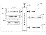
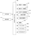
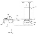
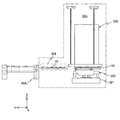
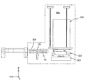
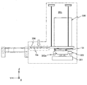
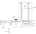
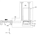
一実施形態に係る露光システムを、レジスト塗布・現像装置とともに示す斜視図である。It is a perspective view which shows the exposure system which concerns on one Embodiment with a resist coating and developing apparatus. 図2(A)は、図1とは異なる角度から見て、一実施形態に係る露光システムを、レジスト塗布・現像装置とともに示す斜視図、図2(B)は、図1及び図2(A)とは異なる角度から見て、一実施形態に係る露光システムを、レジスト塗布・現像装置とともに示す斜視図である。2A is a perspective view showing an exposure system according to an embodiment together with a resist coating / developing apparatus when viewed from an angle different from FIG. 1, and FIG. 2B is a perspective view of FIG. 1 is a perspective view showing an exposure system according to an embodiment together with a resist coating / developing apparatus as viewed from an angle different from FIG. 一実施形態に係る露光システムを、レジスト塗布・現像装置とともに示す平面図である。It is a top view which shows the exposure system which concerns on one Embodiment with a resist coating and developing apparatus. 露光システムのうち、第1制御ラック、フレーム及び第2制御ラックを取り除いた部分を示す斜視図である。It is a perspective view which shows the part which removed the 1st control rack, the flame | frame, and the 2nd control rack among exposure systems. 真空チャンバが備えるロードロックチャンバを、真空チャンバ内部の露光室内部に収容された露光ユニットとともに概略的に示す図である。It is a figure which shows schematically the load lock chamber with which a vacuum chamber is provided with the exposure unit accommodated in the exposure chamber inside the vacuum chamber. 露光ユニットを示す斜視図である。It is a perspective view which shows an exposure unit. 定盤上に載置された粗微動ステージに、ウエハシャトルが装着された状態を示す斜視図である。It is a perspective view which shows the state by which the wafer shuttle was mounted | worn to the coarse / fine movement stage mounted on the surface plate. 微動ステージからウエハシャトルが取り外された図7の粗微動ステージを示す斜視図である。It is a perspective view which shows the coarse / fine movement stage of FIG. 7 from which the wafer shuttle was removed from the fine movement stage. 定盤上に載置された粗微動ステージを拡大して示す図である。It is a figure which expands and shows the coarse / fine movement stage mounted on the surface plate. 図8から微動ステージ及び磁気シールド部材を取り去った状態を示す図である。It is a figure which shows the state which removed the fine movement stage and the magnetic shielding member from FIG. 自重キャセル装置の構成を説明するための図である。It is a figure for demonstrating the structure of a self-weight-cascel apparatus. 図12(A)及び図12(B)は、第1計測系の構成を説明するための図(その1及びその2)である。FIGS. 12A and 12B are views (No. 1 and No. 2) for explaining the configuration of the first measurement system. 図13(A)は、計測室内の各部の構成を説明するための図であり、図13(B)は、図13(A)の計測テーブルの上下方向の可動範囲を説明するための図である。13A is a diagram for explaining the configuration of each part in the measurement chamber, and FIG. 13B is a diagram for explaining the movable range in the vertical direction of the measurement table in FIG. 13A. is there. 露光システムの制御系の構成を示すブロック図である。It is a block diagram which shows the structure of the control system of an exposure system. 図14の制御系を構成する計測制御装置の入出力関係を示すブロック図である。It is a block diagram which shows the input / output relationship of the measurement control apparatus which comprises the control system of FIG. 図14の制御系を構成する露光制御装置の入出力関係を示すブロック図である。It is a block diagram which shows the input / output relationship of the exposure control apparatus which comprises the control system of FIG. 図17(A)は、計測室60内で行われる事前準備作業の一例を説明するためのフローチャート、図17(B)は、計測室60内における露光済みのウエハのアンロード作業を説明するためのフローチャートである。FIG. 17A is a flowchart for explaining an example of the preparatory work performed in the measurement chamber 60, and FIG. 17B is a diagram for explaining the unloading operation of the exposed wafer in the measurement chamber 60. It is a flowchart of. ウエハシャトルと一体でのウエハの交換動作について説明するための図(その1)である。It is FIG. (1) for demonstrating the exchange operation | movement of a wafer integral with a wafer shuttle. ウエハシャトルと一体でのウエハの交換動作について説明するための図(その2)である。FIG. 10 is a diagram (No. 2) for explaining the wafer replacement operation integrally with the wafer shuttle. ウエハシャトルと一体でのウエハの交換動作について説明するための図(その3)である。FIG. 10 is a third diagram for explaining the wafer replacement operation integrated with the wafer shuttle; ウエハシャトルと一体でのウエハの交換動作について説明するための図(その4)である。FIG. 11 is a diagram (No. 4) for explaining the wafer replacement operation integrally with the wafer shuttle. ウエハシャトルと一体でのウエハの交換動作について説明するための図(その5)である。FIG. 11 is a diagram (No. 5) for explaining the wafer replacement operation integrally with the wafer shuttle. ウエハシャトルと一体でのウエハの交換動作について説明するための図(その6)である。FIG. 6 is a diagram (No. 6) for explaining the wafer replacement operation integrally with the wafer shuttle. ウエハシャトルと一体でのウエハの交換動作について説明するための図(その7)である。FIG. 10 is a view (No. 7) for explaining the wafer replacement operation integrally with the wafer shuttle. ウエハシャトルと一体でのウエハの交換動作について説明するための図(その8)である。FIG. 10 is a view (No. 8) for explaining the wafer exchange operation integrally with the wafer shuttle. ウエハシャトルと一体でのウエハの交換動作について説明するための図(その9)である。FIG. 10 is a diagram (No. 9) for explaining the wafer replacement operation integrally with the wafer shuttle. ウエハシャトルと一体でのウエハの交換動作について説明するための図(その10)である。It is FIG. (10) for demonstrating the replacement | exchange operation | movement of the wafer integral with a wafer shuttle.

以下、一実施形態について、図1〜図27に基づいて、説明する。図1〜図2(B)には、一実施形態に係る露光システム1000が、レジスト塗布・現像装置(コータ・デベロッパ(以下、C/Dと略記する))9000とともに、異なる方向から見て斜視図にてそれぞれ示されている。また、図3には、露光システム1000が、C/D9000とともに、平面図にて示されている。   Hereinafter, an embodiment will be described with reference to FIGS. 1 to 2B, an exposure system 1000 according to an embodiment is seen from different directions together with a resist coating / developing apparatus (coater / developer (hereinafter abbreviated as C / D)) 9000. Each is shown in the figure. FIG. 3 shows the exposure system 1000 together with the C / D 9000 in a plan view.

本実施形態では、荷電粒子ビームの一例として、電子ビームを用いた構成について説明する。但し、荷電粒子ビームは、電子ビームに限るものではなく、イオンビーム等の荷電粒子を用いたビームでも構わない。   In this embodiment, a configuration using an electron beam will be described as an example of a charged particle beam. However, the charged particle beam is not limited to an electron beam, and a beam using charged particles such as an ion beam may be used.

本実施形態では、後述するように複数の電子ビーム光学系が設けられているので、以下、各電子ビーム光学系の光軸に平行にZ軸を取り、Z軸に垂直な平面(本実施形態では床面Fと平行な面である)内に互いに直交するY軸及びX軸を取って説明する。   In the present embodiment, since a plurality of electron beam optical systems are provided as will be described later, a plane that takes the Z axis parallel to the optical axis of each electron beam optical system and is perpendicular to the Z axis (this embodiment) In the following description, the Y axis and the X axis that are orthogonal to each other are taken in the plane parallel to the floor surface F).

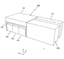
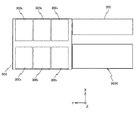
露光システム1000は、図1〜図3に示されるように、床面F上に設置された直方体状のC/D9000に対向して+X側に所定間隔を隔てて配置された直方体状の第1制御ラック200と、C/D9000及び第1制御ラック200の+Y側に配置された複数、例えば6つのチャンバ300〜300と、6つのチャンバ300〜300が配置されたスペースの4つのコーナーに位置する4本の脚部を有するフレーム400と、フレーム400上に配置された第2制御ラック500と、を備えている。 As shown in FIGS. 1 to 3, the exposure system 1000 is a rectangular parallelepiped first arranged at a predetermined interval on the + X side facing a rectangular parallelepiped C / D 9000 installed on the floor surface F. The control rack 200, a plurality of, for example, six chambers 300 1 to 300 6 disposed on the + Y side of the C / D 9000 and the first control rack 200, and four spaces in which six chambers 300 1 to 300 6 are disposed A frame 400 having four legs located at a corner and a second control rack 500 arranged on the frame 400 are provided.

6つのチャンバ300〜300は、3つのチャンバ300〜3003と、3つのチャンバ300〜300とから成る2列に分かれている。
3つのチャンバ300〜300は、互いにX軸方向(後述するチャンバ300とC/D9000とが隣接する方向)に所定間隔を隔てて配置され、また、3つのチャンバ300〜300は、互いにX軸方向(後述するチャンバ3004と第1制御ラック200とが隣接する方向)に所定間隔を隔てて配置される。
The six chambers 300 1 to 300 6 are divided into two rows composed of three chambers 300 1 to 300 3 and three chambers 300 4 to 300 6 .
The three chambers 300 1 to 300 3 are arranged at a predetermined interval in the X-axis direction (a direction in which a chamber 300 1 and C / D 9000 described later are adjacent), and the three chambers 300 1 to 300 3 are It is arranged at a predetermined distance in the X-axis direction (described later chamber 300 4 and the direction in which the first control rack 200 are adjacent) to each other.

図1に示されるチャンバ300〜300が一方の列に含まれ、図2(A)に示されるチャンバ300〜300が他方の列に含まれている。図3の平面図に示されるように、一方の列のチャンバ300〜300は、C/D9000の+Y側に隣接してY軸方向に並んで配置されている。他方の列のチャンバ300〜300は、第1制御ラック200の+Y側に隣接してY軸方向に並んで配置されている。本実施形態では、露光システム1000のうち、第1制御ラック200、フレーム400及び第2制御ラック500を取り除いた部分を示す図4及び図3からわかるように、チャンバ300と300が対向し、チャンバ300と300が対向し、チャンバ300とチャンバ300とが対向している。 The chambers 300 1 to 300 3 shown in FIG. 1 are included in one row, and the chambers 300 4 to 300 6 shown in FIG. 2A are included in the other row. As shown in the plan view of FIG. 3, the chambers 300 1 to 300 3 in one row are arranged side by side in the Y-axis direction adjacent to the + Y side of the C / D 9000. The other rows of chambers 300 4 to 300 6 are arranged adjacent to the + Y side of the first control rack 200 in the Y-axis direction. In the present embodiment, of the exposure system 1000, first control rack 200, as can be seen from FIGS. 4 and 3 shows a partial removal of the frame 400 and the second control rack 500, the chamber 300 1 and 300 4 faces , chamber 300 2 300 5 faces, the chamber 300 3 and the chamber 300 6 faces.

言い換えると、6つのチャンバ300〜300のうち、チャンバ300は、C/D9000に対して、C/D9000が延びる方向に隣接して配置される。
また、6つのチャンバ300〜300のうち、チャンバ300は、チャンバ300とC/D9000とが隣接する方向に対して交差する方向に、かつチャンバ300に対して所定間隔を隔てて配置される。すなわち、チャンバ300とチャンバ300とは、対向して配置される。
そして、第1制御ラック200は、チャンバ300とC/D9000とにそれぞれ所定間隔を隔てて配置される。すなわち、チャンバ300は、第1制御ラック200に対して、第1制御ラック200が延びる方向に隣接して配置され、C/D9000は、第1制御ラック200に対向して配置される。
In other words, among the six chambers 300 1 to 300 6 , the chamber 300 1 is arranged adjacent to the C / D 9000 in the direction in which the C / D 9000 extends.
Of the six chambers 300 1 to 300 6 , the chamber 300 4 is in a direction intersecting the direction in which the chamber 300 1 and the C / D 9000 are adjacent to each other, and at a predetermined interval from the chamber 300 1 . Be placed. That is, the chamber 300 4 and the chamber 300 1, disposed opposite.
Then, the first control rack 200 is arranged in the chamber 300 4 and C / D9000 at a predetermined distance. That is, the chamber 300 4, to the first control rack 200 is disposed adjacent to the direction in which the first control rack 200 extends, C / D9000 is disposed opposite to the first control rack 200.

第1制御ラック200として、C/D9000と同じ長さ且つ同じ高さを有する直方体状のものが用いられている。また、6つのチャンバ300〜300の高さは、第1制御ラック200及びC/D9000の高さよりも低く構成したため、6つのチャンバ300〜300の上方に、空きスペースが存在する。そこで、本実施形態では、この空きスペースを有効活用すべく、第2制御ラック500が、フレーム400を介して配置されている。すなわち、フレーム400は、矩形の天板部とこの天板部を、その4つのコーナー部分で支持する4本の同一長さの脚部とを有し、第2制御ラック500を下方から支持している。第2制御ラック500の上面と、第1制御ラック200及びC/D9000の上面とは、ほぼ同一面となっている。 As the first control rack 200, a rectangular parallelepiped having the same length and the same height as the C / D 9000 is used. Moreover, since the height of the six chambers 300 1 to 300 6 is configured to be lower than the height of the first control rack 200 and the C / D 9000, an empty space exists above the six chambers 300 1 to 300 6 . Therefore, in the present embodiment, the second control rack 500 is arranged via the frame 400 in order to effectively use this empty space. That is, the frame 400 has a rectangular top plate portion and four leg portions of the same length that support the top plate portion at its four corner portions, and supports the second control rack 500 from below. ing. The upper surface of the second control rack 500 and the upper surfaces of the first control rack 200 and the C / D 9000 are substantially the same surface.

このようなレイアウトにより、本実施形態では、クリーンルーム内に直方体状のスペースを作ることができ、クリーンルーム内に使い勝手が悪い空間が生じるのを回避して、空間の利用効率の向上を図ることが可能である。   With this layout, in this embodiment, a rectangular parallelepiped space can be created in the clean room, and it is possible to avoid the occurrence of unusable space in the clean room and to improve the efficiency of use of the space. It is.

第1制御ラック200には、床面Fの下にある、生産支援機器やユーティリティ設備が収容されたクリーンルームサブファブのユーティリティ供給源からの配線及び配管が床面Fを介して下側から接続されている(図2(A)中の上向きの3本の黒矢印参照)。また、第1制御ラック200は、配線及び配管を介して第2制御ラック500に接続されている。配線及び配管は、電力等のユーティリティ(用役、用力)を供給するもので、ユーティリティには、電力の他に、空気、冷却水、真空排気などが含まれる。   To the first control rack 200, wiring and piping from the utility supply source of the clean room subfab that contains the production support equipment and utility facilities below the floor F are connected from below through the floor F. (Refer to the three black arrows pointing upward in FIG. 2A). The first control rack 200 is connected to the second control rack 500 via wiring and piping. The wiring and piping supply utilities (utility, utility) such as electric power, and the utilities include air, cooling water, vacuum exhaust and the like in addition to electric power.

第1制御ラック200の内部には、例えば高電圧電源、及びアンプなどの電子ビーム露光装置に直接関係する制御系ユニット、後述するステージの制御系、及び後述する計測系の制御基板等の様々なユニットが収納されている。第1制御ラック200は、配線及び配管を一旦中継し、クリーンルームサブファブのユーティリティ供給源から配線及び配管(供給部材)を介して供給されたユーティリティを6つのチャンバ300〜300に分配するため(図2(A)中の白抜き矢印参照)、第2制御ラック500に供給する。なお、必要に応じ、第1制御ラック200の内部に、冷却水の温調機を配置しても良い。 Inside the first control rack 200, there are various types such as a control system unit directly related to an electron beam exposure apparatus such as a high voltage power supply and an amplifier, a stage control system described later, and a measurement control board described later. The unit is stored. The first control rack 200 temporarily relays the wiring and piping, and distributes the utility supplied from the utility supply source of the clean room subfab via the wiring and piping (supply member) to the six chambers 300 1 to 300 6. (Refer to the white arrow in FIG. 2 (A)), it is supplied to the second control rack 500. In addition, you may arrange | position the temperature controller of a cooling water inside the 1st control rack 200 as needed.

第2制御ラック500の内部にも、第1制御ラックと同様、様々なユニットが、収容され、配線及び配管を介して6つのチャンバ300〜300のそれぞれに接続されている。第2制御ラック500は、6つのチャンバ300〜300のそれぞれに対して、第1制御ラック200から供給されたユーティリティを上方から供給する(図2(A)中の下向きの3本の黒矢印参照)。すなわち、第2制御ラック500は、第1制御ラック200と6つのチャンバ300〜300とのインターフェースとして機能する。なお、6つのチャンバ300〜300のそれぞれに対して、ユーティリティを上方から供給するメリットについては、後述する。 Similar to the first control rack, various units are accommodated in the second control rack 500 and connected to each of the six chambers 300 1 to 300 6 through wiring and piping. The second control rack 500 supplies the utility supplied from the first control rack 200 from above to each of the six chambers 300 1 to 300 6 (three downward black lines in FIG. 2A). See arrow). That is, the second control rack 500 functions as an interface between the first control rack 200 and the six chambers 300 1 to 300 6 . The merits of supplying the utility from above to each of the six chambers 300 1 to 300 6 will be described later.

6つのチャンバ300〜300のうち、C/D9000に隣接して配置されたチャンバ300は、直方体形状を有している(図4参照)。チャンバ300は、C/D9000にインラインにて接続されている。チャンバ300の内部空間は、ターゲットであるウエハ(C/D9000によって電子線レジストが塗布されたウエハ)に対する所定の計測、及び後述するウエハシャトルに対する露光前のウエハのロード及び露光済みのウエハのアンロードが行われる、計測室(計測セル)60(図1〜図2(B)等では不図示、図13(A)参照)となっている。 Six chambers 300 1 to 300 6 out of, the chamber 300 1 disposed adjacent to the C / D9000 has a rectangular parallelepiped shape (see FIG. 4). Chamber 300 1 is connected by line to the C / D9000. The inner space of the chamber 3001, the wafer predetermined measurement with respect to (C / D9000 wafer electron beam resist is applied by), and unloading of the load and exposed wafer of the wafer before exposure to wafer shuttle to be described later is the target Loading is performed in a measurement chamber (measurement cell) 60 (not shown in FIGS. 1 to 2B, etc., see FIG. 13A).

残りの5つのチャンバ300〜300のうち、チャンバ300〜300は、+Y側から見てL字形状を有し、チャンバ300、300は、これらと左右対称な形状を有している。5つのチャンバ300〜300それぞれの内部空間は、電子ビームによるウエハに対する露光が行われる露光室(露光セル)301(i=2〜6)(図1〜図3等では不図示、図5参照)となっている。露光室301内は、高度の真空状態に維持されている。すなわち、内部に露光室301が形成される5つのチャンバ300としては、大気圧の作用によって押しつぶされたり変形したりすることがない十分な耐性を備えた構造の真空チャンバが用いられている。以下では、チャンバ300〜300を真空チャンバ300〜300とも表記する。 Of the remaining five chambers 300 2 to 300 6 , the chambers 300 4 to 300 6 have an L-shape when viewed from the + Y side, and the chambers 300 2 and 300 3 have a symmetrical shape to these. ing. The internal space of each of the five chambers 300 2 to 300 6 is an exposure chamber (exposure cell) 301 i (i = 2 to 6) in which exposure of the wafer with an electron beam is performed (not shown in FIGS. 1 to 3 and the like). 5). The exposure chamber 301 i is maintained in a high vacuum state. That is, as the five chambers 300 i in which the exposure chambers 301 i are formed, vacuum chambers having a structure with sufficient resistance so as not to be crushed or deformed by the action of atmospheric pressure are used. . Hereinafter, the chamber 300 2-300 6 denoted both vacuum chamber 300 2-300 6.

なお、チャンバ300の内部空間は、上述した計測室になっているため、チャンバ300〜300の内部空間のように真空雰囲気にする必要性がない。そのため、チャンバ300としては、真空チャンバより強度の弱いチャンバを用いることができる。また、チャンバ300の内部空間及びC/D9000の内部空間の圧力をクリーンルームの気圧よりも高くなるように制御することにより、クリーンルーム内の気体(空気)がチャンバ300及びC/D9000内に侵入することを抑制することができる。なお、第1制御ラック200の内部空間及び第2制御ラック500の内部空間のそれぞれは、クリーンルームと同圧力(大気圧空間)、またはクリーンリームの気圧よりも高い圧力に設定しても良い。 The internal space of the chamber 300 1 has extremely measuring chamber as described above, there is no need to vacuum atmosphere as the interior space of the chamber 300 2-300 6. Therefore, as the chamber 300 1, it is possible to use a weak chamber strength than the vacuum chamber. Further, by controlling the pressure of the inner space of the inner space and C / D9000 chamber 300 1 to be higher than pressure of the clean room, a gas in a clean room (air) entering the chamber 300 1 and C / D9000 Can be suppressed. Each of the internal space of the first control rack 200 and the internal space of the second control rack 500 may be set to the same pressure as the clean room (atmospheric pressure space) or a pressure higher than the pressure of the clean dream.

真空チャンバ300には、図5に示されるように、前面に一対のロードロックチャンバ302が取付けられている。なお、図5は、真空チャンバ300、300、300と同じ向きのものが示されているが、真空チャンバ300、300は、図5に示されるものとは左右対称であるが同様の構成を有している。 As shown in FIG. 5, a pair of load lock chambers 302 is attached to the front surface of the vacuum chamber 300 i . FIG. 5 shows the same orientation as the vacuum chambers 300 3 , 300 2 , 300 1 , but the vacuum chambers 300 6 , 300 5 are symmetrical to those shown in FIG. It has the same configuration.

各ロードロックチャンバ302は、その内部にロードロック室304(例えば図19参照)が形成される本体部302aと、本体部302aの前面側(大気側)及び背面側(真空側)に固定された一対のゲート部302b、302cとを含む。一対のゲート部302b、302cには、本体部302aの前面側及び背面側に形成された開口を開閉するシャッタと該シャッタを上下方向にスライド駆動する駆動機構とから成るゲートバルブが設けられている。以下では、ゲート部と同一の符号を用いて、ゲートバルブ302b、302cと表記する。ゲートバルブ302b、302cの開閉(すなわち駆動機構によるシャッタの開閉)は、露光制御装置380(図14、図16参照)によって制御される。 Each load lock chamber 302 is fixed to a main body 302a in which a load lock chamber 304 (see, for example, FIG. 19) is formed, and to the front side (atmosphere side) and back side (vacuum side) of the main body 302a. A pair of gate portions 302b and 302c is included. The pair of gate portions 302b and 302c is provided with a gate valve that includes a shutter that opens and closes an opening formed on the front surface side and the back surface side of the main body portion 302a and a drive mechanism that slides the shutter in the vertical direction. . Hereinafter, gate valves 302b and 302c are denoted by the same reference numerals as those of the gate portion. Opening and closing of the gate valves 302b and 302c (that is, opening and closing of the shutter by the driving mechanism) is controlled by the exposure control device 380 i (see FIGS. 14 and 16).

ロードロックチャンバ302には、真空ポンプ等の真空源に開閉弁305(図16参照)を介して接続された真空配管が接続されており、開閉弁305を開けることで、ロードロック室304の内部は、必要に応じて真空引きが行われる。開閉弁305の開閉も露光制御装置380によって制御される。なお、各ロードロックチャンバ302に、個別に真空ポンプを設けても良い。 A vacuum pipe connected to a vacuum source such as a vacuum pump via an opening / closing valve 305 (see FIG. 16) is connected to the load lock chamber 302. By opening the opening / closing valve 305, the inside of the load lock chamber 304 is connected. Is evacuated as necessary. The opening / closing of the on-off valve 305 is also controlled by the exposure control device 380 i . Each load lock chamber 302 may be provided with a vacuum pump.

真空チャンバ300内部の露光室301内には、図5に示される一対の露光ユニット310と、例えば水平多関節ロボットから成る露光室内搬送系312(図5では不図示、図16参照)が収容されている。また、露光室301内には、図5では不図示であるが、図18等に示されるように、例えば第1の距離離れた上下2段の収納棚を有し、上下動可能なシャトルキャリア306が設けられている。シャトルキャリア306の上下動は、露光制御装置380によって制御される(図16参照)。 In the vacuum chamber 300 i inside the exposure chamber 301 i, a pair of the exposure unit 310 shown in FIG. 5, for example, a horizontal multi-joint consists of a robot exposure chamber transport system 312 (not shown in FIG. 5, see FIG. 16) Contained. Although not shown in FIG. 5 in the exposure chamber 301 i , as shown in FIG. 18 and the like, for example, a shuttle that has two upper and lower storage shelves separated by a first distance and can move up and down is provided. A carrier 306 is provided. The vertical movement of the shuttle carrier 306 is controlled by the exposure control device 380 i (see FIG. 16).

露光ユニット310は、図5に簡略化して示されるように、ステージ装置320と、電子ビーム光学系を有する電子ビーム照射装置330とを含む。
ステージ装置320は、ウエハを保持して移動可能なウエハシャトルが着脱自在に装着される粗微動ステージを含む構成であり、電子ビーム照射装置330は、粗微動ステージに装着されたウエハシャトルに保持されたウエハに電子ビームを照射して露光する構成である。
The exposure unit 310 includes a stage device 320 and an electron beam irradiation device 330 having an electron beam optical system, as shown in a simplified manner in FIG.
The stage device 320 includes a coarse / fine movement stage on which a wafer shuttle that can hold and move a wafer is detachably mounted. The electron beam irradiation device 330 is held by a wafer shuttle mounted on the coarse / fine movement stage. The wafer is exposed by irradiating it with an electron beam.

ここで、ウエハシャトルは、詳しくは後述するが、ウエハを静電吸着して保持する保持部材(あるいはテーブル)であるが、該保持部材がウエハを保持した状態で、保持部材が搬送され、しかもこの保持部材が計測室60を起点として、各露光室301〜301それぞれとの間でシャトルバス(あるいはスペースシャトル)のように繰り返し往復するので、ウエハシャトルと称している。 Here, the wafer shuttle is a holding member (or table) that holds the wafer by electrostatic chucking, as will be described in detail later. However, the holding member is transported while the holding member holds the wafer, and This holding member is referred to as a wafer shuttle because it repeatedly reciprocates like the shuttle bus (or space shuttle) with each of the exposure chambers 301 2 to 30 16 starting from the measurement chamber 60.

ステージ装置320は、図6に示されるように、定盤321と、定盤321上で移動する粗微動ステージ322と、粗微動ステージ322を駆動する駆動系と、粗微動ステージの位置情報を計測する位置計測系とを備えている。ステージ装置320の構成等の詳細は、後述する。   As shown in FIG. 6, the stage device 320 measures the position information of the surface plate 321, the coarse / fine movement stage 322 that moves on the surface plate 321, the drive system that drives the coarse / fine movement stage 322, and the coarse / fine movement stage. A position measuring system. Details of the configuration and the like of the stage device 320 will be described later.

電子ビーム照射装置330は、図6に示されるように、円筒状の鏡筒331と、鏡筒331の内部の電子ビーム光学系とを含む。電子ビーム照射装置330(鏡筒331)は、外周部に中心角120度の間隔で3つの凸部が形成された円環状の板部材から成るメトロロジーフレーム340によって下方から支持されている。より具体的には、鏡筒331の最下端部は、その上の部分に比べて直径が小さい小径部となっており、その小径部とその上の部分との境界部分は段部となっている。そして、その小径部が、メトロロジーフレーム340の円形の開口内に挿入され、段部の底面がメトロロジーフレーム340の上面に当接した状態で、鏡筒331が、メトロロジーフレーム340によって下方から支持されている。メトロロジーフレーム340は、前述の3つの凸部のそれぞれに下端が接続された3つの吊り下げ支持機構350a、350b、350c(柔構造の連結部材)を介して、露光室301を区画する真空チャンバ300の天板(天井壁)から吊り下げ状態で支持されている。すなわち、このようにして、電子ビーム照射装置330は、真空チャンバ300に対して3点で吊り下げ支持されている。 As shown in FIG. 6, the electron beam irradiation apparatus 330 includes a cylindrical lens barrel 331 and an electron beam optical system inside the lens barrel 331. The electron beam irradiation device 330 (lens barrel 331) is supported from below by a metrology frame 340 formed of an annular plate member having three convex portions formed on the outer peripheral portion at intervals of a central angle of 120 degrees. More specifically, the lowermost end portion of the lens barrel 331 is a small-diameter portion whose diameter is smaller than that of the upper portion thereof, and a boundary portion between the small-diameter portion and the upper portion is a stepped portion. Yes. Then, with the small diameter portion inserted into the circular opening of the metrology frame 340 and the bottom surface of the stepped portion in contact with the top surface of the metrology frame 340, the lens barrel 331 is moved from below by the metrology frame 340. It is supported. The metrology frame 340 is a vacuum that divides the exposure chamber 301 i through three suspension support mechanisms 350a, 350b, and 350c (flexible connecting members) each having a lower end connected to each of the three convex portions described above. It is supported in a state suspended from the top plate of the chamber 300 i (ceiling wall). That is, in this way, the electron beam irradiation apparatus 330 is supported by being suspended at three points with respect to the vacuum chamber 300 i .

3つの吊り下げ支持機構350a、350b、350cは、図6中で吊り下げ支持機構350aについて代表的に示されるように、それぞれの上端に設けられた受動型の防振パッド351と、防振パッド(防振部)351の下端にそれぞれの一端が接続され、他端がメトロロジーフレーム340に接続された鋼材より成るワイヤ352とを有する。防振パッド351は、真空チャンバ300の天板に固定され、それぞれエアダンパ又はコイルばねを含む。 The three suspension support mechanisms 350a, 350b, 350c are, as representatively shown for the suspension support mechanism 350a in FIG. 6, a passive vibration isolation pad 351 provided at each upper end, and a vibration isolation pad. (Anti-Vibration Unit) 351 has a wire 352 made of a steel material having one end connected to the lower end of 351 and the other end connected to a metrology frame 340. The anti-vibration pad 351 is fixed to the top plate of the vacuum chamber 300 i and includes an air damper or a coil spring, respectively.

本実施形態では、外部から真空チャンバ300に伝達された床振動などの振動のうちで、電子光学系の光軸に平行なZ軸方向の振動成分の大部分は防振パッド351によって吸収されるため、電子光学系の光軸に平行な方向において高い除振性能が得られる。また、吊り下げ支持機構の固有振動数は、電子光学系の光軸に平行な方向よりも光軸に垂直な方向で低くなっている。3つの吊り下げ支持機構350a、350b、350cは光軸に垂直な方向には振り子のように振動するため、光軸に垂直な方向の除振性能(真空チャンバ300に外部から伝達された床振動などの振動が電子ビーム照射装置330に伝わるのを防止する能力)が十分に高くなるように3つの吊り下げ支持機構350a、350b、350cの長さ(ワイヤ352の長さ)を十分に長く設定している。この構造では高い除振性能が得られるとともに機構部の大幅な軽量化が可能であるが、電子ビーム照射装置330と真空チャンバ300との相対位置が比較的低い周波数で変化するおそれがある。そこで、電子ビーム照射装置330と真空チャンバ300との相対位置を所定の状態に維持するために、非接触方式の位置決め装置353(図5では不図示、図16参照)が設けられている。この位置決め装置353は、例えば国際公開2007/077920などに開示されるように、6軸の加速度センサと、6軸のアクチュエータとを含んで構成することができる。位置決め装置353は、露光制御装置380によって制御される(図16参照)。これにより、真空チャンバ300に対する電子ビーム照射装置330のX軸方向、Y軸方向、Z軸方向の相対位置、及びX軸、Y軸、Z軸の回りの相対回転角は、一定の状態(所定の状態)に維持される。 In the present embodiment, among vibrations such as floor vibration transmitted from the outside to the vacuum chamber 300 i , most of vibration components in the Z-axis direction parallel to the optical axis of the electron optical system are absorbed by the vibration isolation pad 351. Therefore, high vibration isolation performance can be obtained in a direction parallel to the optical axis of the electron optical system. Further, the natural frequency of the suspension support mechanism is lower in the direction perpendicular to the optical axis than in the direction parallel to the optical axis of the electron optical system. Three suspension support mechanisms 350a, 350b, the floor 350c is in a direction perpendicular to the optical axis to oscillate like a pendulum, which is transmitted from the outside to the vibration isolation performance (vacuum chamber 300 i in the direction perpendicular to the optical axis The length of the three suspension support mechanisms 350a, 350b, 350c (the length of the wire 352) is sufficiently long so that the vibration (such as vibration) is sufficiently high). It is set. With this structure, high vibration isolation performance can be obtained and the mechanical unit can be significantly reduced in weight. However, the relative position between the electron beam irradiation device 330 and the vacuum chamber 300 i may change at a relatively low frequency. Therefore, in order to maintain the relative positions of the electron beam irradiation apparatus 330 and the vacuum chamber 300 i to a predetermined state, the positioning device 353 of the non-contact type (not shown in FIG. 5, see FIG. 16) is provided. The positioning device 353 can be configured to include a six-axis acceleration sensor and a six-axis actuator, as disclosed in, for example, International Publication No. 2007/077920. The positioning device 353 is controlled by the exposure control device 380 i (see FIG. 16). As a result, the relative positions of the electron beam irradiation device 330 in the X-axis direction, the Y-axis direction, and the Z-axis direction with respect to the vacuum chamber 300 i and the relative rotation angles around the X-axis, Y-axis, and Z-axis are constant ( (Predetermined state).

本実施形態では、電子ビーム照射装置330は、鏡筒331内に所定の位置関係で配置されたm個(mは例えば100)の光学系カラムから構成される電子ビーム光学系を備えている。各光学系カラムは、個別にオンオフ可能で、かつ偏向可能なn本(nは例えば4000)のビームを照射可能なマルチビーム光学系から成る。マルチビーム光学系としては、例えば特開2011−258842号公報、国際公開第2007/017255号などに開示される光学系と同様の構成のものを用いることができる。4000本のマルチビームが全てオン状態のとき、例えば100μm×20nmの矩形領域(露光領域)内に等間隔に設定された4000点に同時に紫外光露光装置の解像限界よりも小さい(例えば直径20nm)の電子ビームの円形スポットが形成される。   In the present embodiment, the electron beam irradiation device 330 includes an electron beam optical system including m (m is 100, for example) optical system columns arranged in a predetermined positional relationship within the lens barrel 331. Each optical system column is composed of a multi-beam optical system that can irradiate n beams (n is, for example, 4000) that can be individually turned on and off and can be deflected. As the multi-beam optical system, for example, an optical system having the same configuration as the optical system disclosed in Japanese Patent Application Laid-Open No. 2011-258842, International Publication No. 2007/017255, or the like can be used. When all 4000 multi-beams are on, for example, 4000 points set at equal intervals in a rectangular region (exposure region) of 100 μm × 20 nm are simultaneously smaller than the resolution limit of the ultraviolet light exposure apparatus (for example, 20 nm in diameter). ) Of the electron beam circular spot.

100個の光学系カラムは、例えば300mmウエハ上に形成された(あるいはショットマップに従ってこれから形成される)例えば100個のショット領域にほぼ1:1で対応している。本実施形態では、100個の光学系カラムのそれぞれが、それぞれオン/オフ可能で、かつ偏向可能な多数(n=4000)の直径20nm電子ビームの円形スポットを矩形(例えば100μm×20nm)の露光領域内に配置し、この露光領域に対してウエハを走査しながら、その多数の電子ビームの円形スポットを偏向しながらオン/オフすることで、ウエハ上の100個のショット領域が露光され、パターンが形成される。したがって、300mmウエハの場合、露光に際してのウエハの移動ストロークは、多少の余裕を持たせても数十mm、例えば50mmあれば十分である。各光学系カラムは、通常の電子ビーム光学系と同様、反射電子を検出する反射電子検出系(不図示)を備えている。電子ビーム照射装置330は、露光制御装置380によって制御される(図16参照)。 The 100 optical system columns correspond to, for example, approximately 100 shot areas formed on a 300 mm wafer (or formed from a shot map in accordance with a shot map) at a ratio of 1: 1. In this embodiment, each of the 100 optical system columns can be turned on / off, and a large number (n = 4000) of a circular spot of a 20 nm diameter electron beam that can be deflected is exposed in a rectangular shape (for example, 100 μm × 20 nm). 100 shot areas on the wafer are exposed by arranging the pattern within the area and turning on / off while deflecting the circular spots of the multiple electron beams while scanning the wafer with respect to the exposure area. Is formed. Therefore, in the case of a 300 mm wafer, it is sufficient that the movement stroke of the wafer at the time of exposure is several tens of mm, for example, 50 mm even with some margin. Each optical system column includes a reflected electron detection system (not shown) that detects reflected electrons in the same manner as a normal electron beam optical system. The electron beam irradiation device 330 is controlled by an exposure control device 380 i (see FIG. 16).

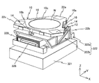
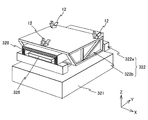
次にステージ装置320の構成等について説明する。図7には、ステージ装置320の粗微動ステージ322に、ウエハシャトル(以下、シャトルと略記する)10が装着された状態の斜視図が示されている。図8には、シャトル10が離脱された(取り外された)状態の図7に示される粗微動ステージ322の斜視図が示されている。   Next, the configuration and the like of the stage device 320 will be described. FIG. 7 is a perspective view showing a state where a wafer shuttle (hereinafter abbreviated as shuttle) 10 is mounted on the coarse / fine movement stage 322 of the stage device 320. FIG. 8 is a perspective view of the coarse / fine movement stage 322 shown in FIG. 7 in a state in which the shuttle 10 is detached (removed).

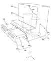
ステージ装置320が備える定盤321は、実際には、露光室301を区画する真空チャンバ300の底壁上に設置されている。粗微動ステージ322は、図7及び図8に示されるように、Y軸方向に所定間隔を隔てて配置され、X軸方向にそれぞれ延びる一対の四角柱状の部分を含み、定盤321上でX軸方向に所定ストローク、例えば50mmで移動可能な粗動ステージ322aと、粗動ステージ322aに対してY軸方向に所定ストローク、例えば50mmで移動可能で、かつ残りの5自由度方向、すなわちX軸方向、Z軸方向、X軸周りの回転方向(θx方向)、Y軸周りの回転方向(θy方向)及びZ軸周りの回転方向(θz方向)にX軸方向に比べて短いストロークで可動な微動ステージ322bと、を備えている。なお、図示は省略されているが、粗動ステージ322aの一対の四角柱状の部分は、実際には、微動ステージ322bのY軸方向の移動を妨げない状態で不図示の連結部材によって連結され、一体化されている。 The surface plate 321 provided in the stage device 320 is actually installed on the bottom wall of the vacuum chamber 300 i that partitions the exposure chamber 301 i . As shown in FIGS. 7 and 8, the coarse / fine movement stage 322 includes a pair of quadrangular columnar portions that are arranged at predetermined intervals in the Y-axis direction and extend in the X-axis direction. A coarse movement stage 322a that can move in the axial direction with a predetermined stroke, for example 50 mm, and a coarse movement stage 322a that can move in the Y axis direction with a predetermined stroke, for example, 50 mm, and the remaining five degrees of freedom, that is, the X axis Direction, Z-axis direction, rotation direction around the X-axis (θx direction), rotation direction around the Y-axis (θy direction), and rotation direction around the Z-axis (θz direction) with a shorter stroke than the X-axis direction A fine movement stage 322b. Although not shown, the pair of square columnar portions of the coarse movement stage 322a are actually connected by a connecting member (not shown) in a state that does not prevent the movement of the fine movement stage 322b in the Y-axis direction, It is integrated.

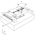
粗動ステージ322aは、粗動ステージ駆動系323(図16参照)によって、X軸方向に所定ストローク(例えば50mm)で駆動される(図10のX軸方向の長い矢印参照)。粗動ステージ駆動系323は、本実施形態では磁束漏れが生じない一軸駆動機構、例えばボールねじを用いた送りねじ機構によって構成される。この粗動ステージ駆動系323は、粗動ステージの一対の四角柱状の部分のうち、一方の四角柱状の部分と定盤321との間に配置される。例えば、定盤321にねじ軸が取り付けられ、一方の四角柱状の部分にボール(ナット)が取り付けられる構成である。なお、定盤321にボールを取り付け、一方の四角柱状の部分にねじ軸を取り付ける構成であっても良い。   The coarse movement stage 322a is driven with a predetermined stroke (for example, 50 mm) in the X-axis direction by a coarse movement stage drive system 323 (see FIG. 16) (see a long arrow in the X-axis direction in FIG. 10). In this embodiment, the coarse movement stage drive system 323 is configured by a uniaxial drive mechanism that does not cause magnetic flux leakage, for example, a feed screw mechanism using a ball screw. The coarse movement stage drive system 323 is disposed between one square columnar portion and the surface plate 321 of the pair of square columnar portions of the coarse movement stage. For example, a screw shaft is attached to the surface plate 321 and a ball (nut) is attached to one quadrangular columnar portion. In addition, the structure which attaches a ball | bowl to the surface plate 321 and attaches a screw shaft to one square pillar-shaped part may be sufficient.

また、粗動ステージの一対の四角柱状の部分のうち、他方の四角柱状の部分は、定盤321に設けられた不図示のガイド面に沿って移動する構成である。
ボールねじのねじ軸は、ステッピングモータによって回転駆動される。あるいは、粗動ステージ駆動系323を、駆動源として超音波モータを備えた一軸駆動機構によって構成しても良い。いずれにしても、磁束漏れに起因する磁場変動が電子ビームの位置決めに影響を与えることはない。粗動ステージ駆動系323は、露光制御装置380によって制御される(図16参照)。
In addition, of the pair of quadrangular columnar portions of the coarse movement stage, the other quadrangular columnar portion is configured to move along a guide surface (not shown) provided on the surface plate 321.
The screw shaft of the ball screw is driven to rotate by a stepping motor. Alternatively, the coarse movement stage drive system 323 may be configured by a uniaxial drive mechanism including an ultrasonic motor as a drive source. In any case, the magnetic field fluctuation caused by the magnetic flux leakage does not affect the positioning of the electron beam. The coarse movement stage drive system 323 is controlled by the exposure control device 380 i (see FIG. 16).

微動ステージ322bは、図9の斜視図に拡大して示されるように、Y軸方向に貫通したXZ断面矩形枠状の部材から成り、重量キャンセル装置324によって、定盤321上でXY平面内で移動可能に支持されている。微動ステージ322bの側壁の外面には、補強用のリブが複数設けられている。なお、重量キャンセル装置324の構成については、後述する。   As shown in the enlarged perspective view of FIG. 9, the fine movement stage 322 b is formed of a member having an XZ cross-sectional rectangular frame shape penetrating in the Y-axis direction. The weight cancellation device 324 allows the fine movement stage 322 b on the surface plate 321 in the XY plane. It is supported movably. A plurality of reinforcing ribs are provided on the outer surface of the side wall of fine movement stage 322b. The configuration of the weight cancellation device 324 will be described later.

微動ステージ322bの中空部の内部には、XZ断面が矩形枠状でY軸方向に延びるヨーク325aと、ヨーク325aの上下の対向面に固定された一対の磁石ユニット325bとが設けられ、これらヨーク325aと一対の磁石ユニット325bによって、微動ステージ322bを駆動するモータの可動子325が構成されている。   Inside the hollow portion of fine movement stage 322b, there are provided a yoke 325a having an XZ cross section in a rectangular frame shape and extending in the Y-axis direction, and a pair of magnet units 325b fixed to the upper and lower opposing surfaces of yoke 325a. A mover 325 of a motor that drives fine movement stage 322b is configured by 325a and a pair of magnet units 325b.

この可動子325に対応して、粗動ステージ322aの一対の四角柱部分の相互間には、図8から微動ステージ322b及び符号328で示される後述する磁気シールド部材を取り去った状態を示す図10に示されるように、コイルユニットから成る固定子326が架設されている。固定子326と前述の可動子325とによって、可動子325を固定子326に対して、図10に各方向の矢印で示されるように、Y軸方向に所定ストローク、例えば50mmで移動可能で、かつX軸方向、Z軸方向、θx方向、θy方向及びθz方向に微小駆動可能な閉磁界型かつムービングマグネット型のモータ327が構成されている。本実施形態では、モータ327によって微動ステージを6自由度方向に駆動する微動ステージ駆動系が構成されている。以下、微動ステージ駆動系をモータと同一の符号を用いて、微動ステージ駆動系327と表記する。微動ステージ駆動系327は、露光制御装置380によって制御される(図16参照)。 Corresponding to the mover 325, FIG. 10 shows a state in which a magnetic shield member (to be described later) indicated by the fine movement stage 322b and the reference numeral 328 is removed from the pair of rectangular column parts of the coarse movement stage 322a from FIG. As shown in FIG. 2, a stator 326 made of a coil unit is installed. The stator 326 and the above-described mover 325 can move the mover 325 with respect to the stator 326 with a predetermined stroke, for example, 50 mm in the Y-axis direction, as indicated by arrows in each direction in FIG. In addition, a closed magnetic field type and moving magnet type motor 327 that can be finely driven in the X axis direction, the Z axis direction, the θx direction, the θy direction, and the θz direction is configured. In the present embodiment, a fine movement stage drive system that drives the fine movement stage in the direction of six degrees of freedom by the motor 327 is configured. Hereinafter, the fine movement stage drive system is referred to as a fine movement stage drive system 327 using the same reference numerals as those of the motor. Fine movement stage drive system 327 is controlled by exposure control device 380 i (see FIG. 16).

粗動ステージ322aの一対の四角柱部分の相互間には、例えば図7及び図8などに示されるように、さらに、モータ327の上面及びX軸方向の両側面を覆う状態でXZ断面逆U字状の磁気シールド部材328が架設されている。すなわち、磁気シールド部材328は、四角柱部分が延びる方向に交差する方向(Y軸方向)に延びて形成されており、モータ327の上面に非接触で対向する上面部と、モータ327の側面に非接触で対向する側面部とを備える。この磁気シールド部材328は、微動ステージ322bの中空部内に挿入された状態で、側面部のうち、長手方向(Y軸方向)の両端部の下面が粗動ステージ322aの一対の四角柱部分の上面に固定されている。また、磁気シールド部材328の側面部のうち、上記両端部の下面以外は、微動ステージ322bの内壁面のうち、底壁面(下面)に対して、非接触で対向する。すなわち、磁気シールド部材328は、可動子325の固定子326に対する移動を妨げることがない状態で、微動ステージ322bの中空部内に挿入されている。   Between the pair of quadrangular prism portions of the coarse movement stage 322a, as shown in FIG. 7 and FIG. 8, for example, the XZ cross-section reverse U in a state of covering the upper surface of the motor 327 and both side surfaces in the X-axis direction. A letter-shaped magnetic shield member 328 is installed. In other words, the magnetic shield member 328 is formed to extend in a direction (Y-axis direction) intersecting the direction in which the quadrangular prism portion extends, and on the upper surface of the motor 327 in a non-contact manner and on the side surface of the motor 327. And a side portion that faces each other in a non-contact manner. The magnetic shield member 328 is inserted into the hollow portion of the fine movement stage 322b, and the lower surface of both end portions in the longitudinal direction (Y-axis direction) of the side surface portions is the upper surface of the pair of square pillar portions of the coarse movement stage 322a. It is fixed to. Further, of the side surfaces of the magnetic shield member 328, the surfaces other than the lower surfaces of the both end portions are opposed to the bottom wall surface (lower surface) of the inner wall surface of the fine movement stage 322b in a non-contact manner. That is, the magnetic shield member 328 is inserted into the hollow portion of the fine movement stage 322b without hindering the movement of the mover 325 relative to the stator 326.

磁気シールド部材328としては、所定の空隙(スペース)を隔てて積層された複数層の磁性材料のフィルムによって構成されるラミネートな磁気シールド部材が用いられている。この他、透磁率の異なる2種類の材料のフィルムが交互に積層された構成の磁気シールド部材を用いても良い。磁気シールド部材328は、モータ327の上面及び側面を、可動子325の移動ストロークの全長に渡って覆っており、かつ粗動ステージ322aに固定されているので、微動ステージ322b及び粗動ステージ322aの移動範囲の全域で、上方(電子ビーム照射光学系側)への磁束の漏れをほぼ確実に防止することができる。   As the magnetic shield member 328, a laminated magnetic shield member composed of a plurality of layers of magnetic material films laminated with a predetermined gap (space) therebetween is used. In addition, a magnetic shield member having a configuration in which films of two kinds of materials having different magnetic permeability are alternately laminated may be used. Since the magnetic shield member 328 covers the upper surface and side surfaces of the motor 327 over the entire length of the moving stroke of the mover 325 and is fixed to the coarse movement stage 322a, the fine movement stage 322b and the coarse movement stage 322a Leakage of magnetic flux upward (on the electron beam irradiation optical system side) can be almost certainly prevented over the entire moving range.

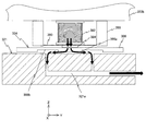
重量キャンセル装置324は、図11に示されるように、微動ステージ322bの下面に上端が接続された金属製のベローズ型空気ばね(以下、空気ばねと略記する)382と、空気ばね382の下端に接続された平板状の板部材から成るベーススライダ386と、を有している。空気ばね382とベーススライダ386とは、中央に開口が形成された板状の接続部材384を介して互いに接続されている。   As shown in FIG. 11, the weight cancellation device 324 includes a metal bellows type air spring (hereinafter abbreviated as “air spring”) 382 having an upper end connected to the lower surface of the fine movement stage 322 b, and a lower end of the air spring 382. And a base slider 386 made of a flat plate member connected thereto. The air spring 382 and the base slider 386 are connected to each other via a plate-like connection member 384 having an opening at the center.

ベーススライダ386には、空気ばね382内部の空気を、定盤321の上面に噴き出す軸受部386aが空気ばね382の下方に設けられ、軸受部386aから噴出される加圧空気の軸受面と定盤321上面との間の静圧(隙間内圧力)により、ベーススライダ386、重量キャンセル装置324、微動ステージ322b及び可動子325(後述するように、シャトルが粗微動ステージ322に装着された場合には、そのシャトル10等も含む)の自重が支持されている。なお、空気ばね382には、微動ステージ322bに接続された不図示の配管を介して圧縮空気が供給されている。   The base slider 386 is provided with a bearing portion 386a for blowing air inside the air spring 382 to the upper surface of the surface plate 321 below the air spring 382, and a bearing surface for the pressurized air ejected from the bearing portion 386a and the surface plate. The base slider 386, the weight cancellation device 324, the fine movement stage 322b, and the mover 325 (as will be described later, when the shuttle is mounted on the coarse / fine movement stage 322) due to the static pressure (pressure in the gap) between the upper surface and the upper surface 321. , Including the shuttle 10 and the like). Note that compressed air is supplied to the air spring 382 via a pipe (not shown) connected to the fine movement stage 322b.

ベーススライダ386の定盤321に対向する面(下面)には、軸受部386aの周囲に環状の凹部386bが形成され、これに対応して定盤321には、軸受部386aから凹部386bと定盤321の上面とで区画される空間内に噴出された空気を、外部に真空排気するための排気路321aが形成されている。ベーススライダ386の凹部386bは、微動ステージ322bが定盤321上でXY平面内の移動可能な範囲のどこに移動しても、凹部386bに排気路321aの排気口が対向する状態が維持されるような寸法を有している。すなわち、ベーススライダ386の下方に一種の差動排気型の空気静圧軸受が構成され、軸受部386aから定盤321に向かって噴出された空気が、周囲に(露光室内に)漏れ出すことが防止されている。   An annular recess 386b is formed around the bearing portion 386a on the surface (lower surface) of the base slider 386 that faces the platen 321. Correspondingly, the platen 321 is fixed to the recess 386b from the bearing portion 386a. An exhaust path 321a for evacuating the air blown into the space defined by the upper surface of the board 321 to the outside is formed. The recess 386b of the base slider 386 is maintained so that the exhaust port of the exhaust path 321a faces the recess 386b regardless of where the fine movement stage 322b moves on the surface plate 321 within the movable range in the XY plane. Have various dimensions. That is, a kind of differential exhaust type aerostatic bearing is formed below the base slider 386, and the air ejected from the bearing portion 386a toward the surface plate 321 may leak out to the surroundings (into the exposure chamber). It is prevented.

微動ステージ322bの下面には、空気ばね382を挟んで一対の支柱(ピラー)388が固定されている。一対の支柱388は、空気ばね382のX軸方向の両側で、かつ空気ばね382を中心として左右対称な配置で、Z軸方向の長さが空気ばね382より幾分長い。一対の支柱388それぞれの下端には、空気ばね382の下端面に一端がそれぞれ接続された平面視U字状の一対の板ばね390の他端がそれぞれ接続されている。この場合、一対の板ばね390は、U字の先端部(二股に別れた部分)が空気ばね382に接続され、反対側の端部が一対の支柱388それぞれに接続されている。一対の板ばね390とベーススライダ386とは、ほぼ平行であり、両者の間には所定の間隙が形成されている。   A pair of pillars 388 are fixed to the lower surface of fine movement stage 322b with air spring 382 interposed therebetween. The pair of struts 388 are arranged symmetrically on both sides in the X-axis direction of the air spring 382 and centered on the air spring 382, and the length in the Z-axis direction is slightly longer than that of the air spring 382. The other ends of a pair of leaf springs 390 having a U-shape in plan view, each having one end connected to the lower end surface of the air spring 382, are connected to the lower ends of the pair of support columns 388, respectively. In this case, the pair of leaf springs 390 has U-shaped tip portions (portions separated into two portions) connected to the air spring 382 and opposite end portions connected to the pair of support columns 388, respectively. The pair of leaf springs 390 and the base slider 386 are substantially parallel, and a predetermined gap is formed between them.

微動ステージ322bのXY平面内の移動の際にベーススライダ386に作用する水平方向の力を、一対の板ばね390が受けることができるので、微動ステージ322bのXY平面内の移動の際に、不要な力が空気ばね382に作用するのをほぼ確実に防止できる。また、一対の板ばね390は、微動ステージ322bがチルト駆動される際には、そのチルトを許容するように変形する。   Since the pair of leaf springs 390 can receive the horizontal force acting on the base slider 386 when the fine movement stage 322b moves in the XY plane, it is not necessary when the fine movement stage 322b moves in the XY plane. It is possible to almost certainly prevent a large force from acting on the air spring 382. The pair of leaf springs 390 are deformed to allow the tilt when the fine movement stage 322b is driven to tilt.

ここで、シャトル10を粗微動ステージ322、より正確には微動ステージ322bに着脱自在に装着するための構造について説明する。   Here, a structure for detachably mounting the shuttle 10 to the coarse / fine movement stage 322, more precisely, to the fine movement stage 322b will be described.

微動ステージ322bの上面には、図8に示されるように、3つの三角錐溝部材12が設けられている。この三角錐溝部材12は、例えば、平面視でほぼ正三角形の3つの頂点の位置に設けられている。この三角錐溝部材12には、後述するシャトル10に設けられた球体又は半球体が係合可能であり、この球体又は半球体とともにキネマティックカップリングを構成する。なお、図8には、3つの板部材によって構成された花弁のような三角錐溝部材12が示されているが、この三角錐溝部材12は、球体又半球体にそれぞれ点接触する三角錐溝と同じ役割を有するので、三角錐溝部材と称している。したがって、三角錐溝が形成された単一の部材を、三角錐溝部材12の代わりに用いても良い。   As shown in FIG. 8, three triangular pyramid groove members 12 are provided on the upper surface of fine movement stage 322b. For example, the triangular pyramidal groove member 12 is provided at the positions of three apexes of a regular triangle in plan view. The triangular pyramid groove member 12 can be engaged with a sphere or hemisphere provided in the shuttle 10 described later, and constitutes a kinematic coupling together with the sphere or hemisphere. FIG. 8 shows a triangular pyramid groove member 12 such as a petal composed of three plate members. The triangular pyramid groove member 12 is a triangular pyramid that makes point contact with a sphere or a hemisphere, respectively. Since it has the same role as the groove, it is called a triangular pyramid groove member. Therefore, a single member in which a triangular pyramid groove is formed may be used instead of the triangular pyramid groove member 12.

本実施形態では、3つの三角錐溝部材12に対応して、図7に示されるように、シャトル10に3つの球体又は半球体(本実施形態ではボール)14が設けられている。シャトル10は、平面視で正三角形の各頂点を切り落としたような六角形状で形成されている。これをさらに詳述すると、シャトル10には、平面視で3つの斜辺それぞれの中央部に切り欠き部10a、10b、10cが形成され、切り欠き部10a、10b、10cをそれぞれ外側から覆う状態で、板ばね16がそれぞれ取り付けられている。各板ばね16の長手方向の中央部にボール14がそれぞれ固定されている。三角錐溝部材12に係合される前の状態では、各ボール14は、外力を受けた場合、シャトル10の中心(図7に示されるウエハWの中心にほぼ一致)を中心とする半径方向にのみ微小移動する。   In the present embodiment, as shown in FIG. 7, three spheres or hemispheres (balls in the present embodiment) 14 are provided in the shuttle 10 corresponding to the three triangular pyramidal groove members 12. The shuttle 10 is formed in a hexagonal shape in which each vertex of an equilateral triangle is cut off in plan view. More specifically, the shuttle 10 has notches 10a, 10b, and 10c formed at the center of each of the three oblique sides in plan view, and covers the notches 10a, 10b, and 10c from the outside. The leaf springs 16 are respectively attached. Balls 14 are fixed to the center of each leaf spring 16 in the longitudinal direction. In a state before being engaged with the triangular pyramid groove member 12, each ball 14, when subjected to an external force, has a radial direction centered on the center of the shuttle 10 (substantially coincides with the center of the wafer W shown in FIG. 7). Only move to a minute.

微動ステージ322bの上方で3つの三角錐溝部材12にほぼ対向する位置に、シャトル10の3つのボール14を移動させた後、シャトル10を降下させることにより、3つのボール14のそれぞれが、3つの三角錐溝部材12に個別に係合し、シャトル10が微動ステージ322bに装着される。この装着時に、シャトル10の微動ステージ322bに対する位置が所望の位置からずれていたとしても、ボール14が三角錐溝部材12に係合する際にその三角錐溝部材12から外力を受けて前述の如く半径方向に移動する結果、3つのボール14が対応する三角錐溝部材12に、常に同じ状態で係合する。一方、シャトル10を上方に移動させて、ボール14と三角錐溝部材12との係合を解除するだけで、シャトル10を微動ステージ322bから簡単に取り外す(離脱させる)ことができる。すなわち、本実施形態では3組のボール14と三角錐溝部材12との組によって、キネマティックカップリングが構成され、このキネマティックカップリングによって、シャトル10の微動ステージ322bに対する取り付け状態を常にほぼ同一状態に設定することができるようになっている。したがって、何度、取り外しても、再度、シャトル10をキネマティックカップリング(3組のボール14と三角錐溝部材12との組)を介して微動ステージ322bに装着するだけで、シャトル10と微動ステージ322bとの一定の位置関係を、再現することができる。   After moving the three balls 14 of the shuttle 10 to a position substantially opposite to the three triangular pyramidal groove members 12 above the fine movement stage 322b, the shuttle 10 is moved down so that each of the three balls 14 becomes 3 The shuttle 10 is attached to the fine movement stage 322b by individually engaging with the three triangular pyramid groove members 12. Even when the position of the shuttle 10 with respect to the fine movement stage 322b is deviated from a desired position at the time of mounting, when the ball 14 is engaged with the triangular pyramid groove member 12, an external force is received from the triangular pyramid groove member 12 to As a result of the radial movement, the three balls 14 always engage with the corresponding triangular pyramidal groove members 12 in the same state. On the other hand, the shuttle 10 can be easily detached (detached) from the fine movement stage 322b only by moving the shuttle 10 upward and releasing the engagement between the ball 14 and the triangular pyramid groove member 12. In other words, in this embodiment, a kinematic coupling is constituted by the set of three balls 14 and the triangular pyramid groove member 12, and the kinematic coupling ensures that the mounting state of the shuttle 10 with respect to the fine movement stage 322b is always substantially the same. It can be set to the state. Therefore, no matter how many times it is removed, the shuttle 10 can be moved slightly together with the shuttle 10 only by mounting the shuttle 10 on the fine movement stage 322b via the kinematic coupling (the set of three balls 14 and the triangular pyramid groove member 12). A certain positional relationship with the stage 322b can be reproduced.

シャトル10の上面には、例えば図7に示されるように、中央にウエハWより僅かに直径が大きな円形の凹部が形成され、該凹部内に不図示の静電チャックが設けられ、該静電チャックによってウエハWが静電吸着され保持されている。このウエハWの保持状態では、ウエハWの表面は、シャトル10の上面とほぼ同一面となっている。シャトル10にはウエハWの載置面(吸着面)に上下に貫通する円形開口(不図示)が複数、所定の位置関係で形成されている。   On the upper surface of the shuttle 10, for example, as shown in FIG. 7, a circular concave portion having a diameter slightly larger than that of the wafer W is formed at the center, and an electrostatic chuck (not shown) is provided in the concave portion. The wafer W is electrostatically attracted and held by the chuck. In the holding state of the wafer W, the surface of the wafer W is substantially flush with the upper surface of the shuttle 10. The shuttle 10 is formed with a plurality of circular openings (not shown) penetrating vertically on the mounting surface (suction surface) of the wafer W in a predetermined positional relationship.

次に、粗微動ステージ322の位置情報を計測する位置計測系について説明する。この位置計測系は、シャトル10が微動ステージ322bに前述したキネマティックカップリングを介して装着された状態で、シャトル10の位置情報を計測する。この位置計測計は、シャトル10が装着された微動ステージ322bの位置情報を計測する第1計測系20と、微動ステージ322bの位置情報を直接計測する第2計測系25とを含む(図16参照)。   Next, a position measurement system that measures position information of the coarse / fine movement stage 322 will be described. This position measurement system measures the position information of the shuttle 10 in a state where the shuttle 10 is mounted on the fine movement stage 322b via the kinematic coupling described above. This position meter includes a first measurement system 20 that measures position information of the fine movement stage 322b on which the shuttle 10 is mounted, and a second measurement system 25 that directly measures position information of the fine movement stage 322b (see FIG. 16). ).

まず、第1計測系20について説明する。シャトル10の前述の3つの斜辺を除く3つの辺それぞれの近傍には、図7に示されるように、グレーティングプレート22a、22b、22cがそれぞれ設けられている。グレーティングプレート22a、22b、22cのそれぞれには、シャトル10の中心(本実施形態では円形の凹部の中心に一致)を中心とする半径方向とこれに直交するする方向のそれぞれを周期方向とする2次元格子がそれぞれ形成されている。例えば、グレーティングプレート22aには、Y軸方向及びX軸方向を周期方向とする2次元格子が形成されている。また、グレーティングプレート22bには、シャトル10の中心に関してY軸に対して−120度を成す方向(以下、α方向と称する)及びこれに直交する方向を周期方向とする2次元格子が形成され、グレーティングプレート22cには、シャトル10の中心に関してY軸に対して+120度を成す方向(以下、β方向と称する)及びこれに直交する方向を周期方向とする2次元格子が形成されている。2次元格子としては、それぞれの周期方向について、ピッチが例えば1μmの反射型の回折格子が用いられている。   First, the first measurement system 20 will be described. Grating plates 22a, 22b, and 22c are provided in the vicinity of the three sides of the shuttle 10 except for the three oblique sides, as shown in FIG. Each of the grating plates 22a, 22b, and 22c has a periodic direction in each of a radial direction centered on the center of the shuttle 10 (which coincides with the center of the circular concave portion in this embodiment) and a direction orthogonal thereto. A dimensional lattice is formed. For example, the grating plate 22a is formed with a two-dimensional grating having a periodic direction in the Y-axis direction and the X-axis direction. In addition, the grating plate 22b is formed with a two-dimensional grating having a direction that is −120 degrees with respect to the Y axis with respect to the center of the shuttle 10 (hereinafter referred to as α direction) and a direction perpendicular thereto as a periodic direction. The grating plate 22c is formed with a two-dimensional lattice having a direction that is +120 degrees with respect to the Y axis with respect to the center of the shuttle 10 (hereinafter referred to as a β direction) and a direction perpendicular thereto as a periodic direction. As the two-dimensional grating, a reflection type diffraction grating having a pitch of, for example, 1 μm is used in each periodic direction.

3つのグレーティングプレート22a、22b、22cに対応して、図12(A)に示されるように、メトロロジーフレーム340の下面(−Z側の面)には、3つのグレーティングプレート22a、22b、22cのそれぞれに個別に対向可能な位置に、3つのヘッド部24a、24b、24cが固定されている。3つのヘッド部24a、24b、24cのそれぞれには、図12(B)中に各4本の矢印で示される計測軸を有する4軸エンコーダヘッドが設けられている。   Corresponding to the three grating plates 22a, 22b, and 22c, as shown in FIG. 12A, on the lower surface (the surface on the −Z side) of the metrology frame 340, there are three grating plates 22a, 22b, and 22c. Three head portions 24a, 24b, and 24c are fixed at positions that can individually face each of the head portions 24a, 24b, and 24c. Each of the three head portions 24a, 24b, and 24c is provided with a 4-axis encoder head having measurement axes indicated by four arrows in FIG. 12B.

これをさらに詳述すると、ヘッド部24aは、同一の筐体の内部に収容された、X軸方向及びZ軸方向を計測方向とする第1ヘッドと、Y軸方向及びZ軸方向を計測方向とする第2ヘッドとを含む。第1ヘッド(より正確には、第1ヘッドが発する計測ビームのグレーティングプレート22a上の照射点)と、第2ヘッド(より正確には、第2ヘッドが発する計測ビームのグレーティングプレート22a上の照射点)とは、同一のX軸に平行な直線上に配置されている。ヘッド部24aの第1ヘッド及び第2ヘッドは、それぞれグレーティングプレート22aを用いて、シャトル10のX軸方向及びZ軸方向の位置情報を計測する2軸リニアエンコーダ、及びY軸方向及びZ軸方向の位置情報を計測する2軸リニアエンコーダを構成する。   More specifically, the head portion 24a includes a first head housed in the same housing and having a measurement direction in the X-axis direction and the Z-axis direction, and a measurement direction in the Y-axis direction and the Z-axis direction. And a second head. The first head (more precisely, the irradiation point on the grating plate 22a of the measurement beam emitted by the first head) and the second head (more precisely, the irradiation of the measurement beam emitted by the second head on the grating plate 22a). Are arranged on a straight line parallel to the same X axis. The first head and the second head of the head portion 24a are each a biaxial linear encoder that measures position information of the shuttle 10 in the X-axis direction and the Z-axis direction using the grating plate 22a, and the Y-axis direction and the Z-axis direction. A two-axis linear encoder that measures the position information is configured.

残りのヘッド部24b、24cは、それぞれのメトロロジーフレーム340に対する向きが異なる(XY平面内における計測方向が異なる)が、第1ヘッドと第2ヘッドとを含んでヘッド部24aと同様に構成されている。ヘッド部24bの第1ヘッド及び第2ヘッドは、それぞれグレーティングプレート22bを用いて、シャトル10のα方向にXY平面内で直交する方向及びZ軸方向の位置情報を計測する2軸リニアエンコーダ、及びα方向及びZ軸方向の位置情報を計測する2軸リニアエンコーダを構成する。ヘッド部24cの第1ヘッド及び第2ヘッドは、それぞれグレーティングプレート22cを用いて、シャトル10のβ方向にXY平面内で直交する方向及びZ軸方向の位置情報を計測する2軸リニアエンコーダ、及びβ方向及びZ軸方向の位置情報を計測する2軸リニアエンコーダを構成する。   The remaining head portions 24b and 24c are configured in the same manner as the head portion 24a including the first head and the second head, although the directions with respect to the respective metrology frames 340 are different (measurement directions in the XY plane are different). ing. The first head and the second head of the head unit 24b each use a grating plate 22b, a biaxial linear encoder that measures position information in the direction orthogonal to the α direction of the shuttle 10 in the XY plane and in the Z axis direction, and A two-axis linear encoder that measures position information in the α direction and the Z-axis direction is configured. The first head and the second head of the head unit 24c each use a grating plate 22c to measure position information in a direction orthogonal to the β direction of the shuttle 10 in the XY plane and position information in the Z-axis direction, and A two-axis linear encoder that measures position information in the β direction and the Z-axis direction is configured.

ヘッド部24a、24b、24cそれぞれが有する第1ヘッド及び第2ヘッドのそれぞれとしては、例えば米国特許第7,561,280号明細書に開示される変位計測センサヘッドと同様の構成のエンコーダヘッドを用いることができる。   As each of the first head and the second head included in each of the head portions 24a, 24b, and 24c, for example, an encoder head having the same configuration as the displacement measurement sensor head disclosed in US Pat. No. 7,561,280 is used. Can be used.

上述した3組、合計6つの2軸エンコーダ、すなわち3つのグレーティングプレート22a、22b、22cをそれぞれ用いてシャトル10の位置情報を計測する3つのヘッド部24a、24b、24cによって、エンコーダシステムが構成され、このエンコーダシステムによって第1計測系20(図16参照)が構成されている。第1計測系20で計測される位置情報は、露光制御装置380に供給される。 An encoder system is configured by the three head portions 24a, 24b, and 24c that measure the position information of the shuttle 10 using the above-described three sets, that is, a total of six biaxial encoders, that is, three grating plates 22a, 22b, and 22c, respectively. The encoder system constitutes the first measurement system 20 (see FIG. 16). Position information measured by the first measurement system 20 is supplied to the exposure control device 380 i .

第1計測系20は、3つのヘッド部24a、24b、24cがそれぞれ4つの計測自由度(計測軸)を有しているので、合計12自由度の計測が可能である。すなわち、3次元空間内では、自由度は最大で6であるから、実際には、6自由度方向のそれぞれについて、冗長計測が行われ、各2つの位置情報が得られることになる。   In the first measurement system 20, since the three head portions 24a, 24b, and 24c each have four measurement degrees of freedom (measurement axes), a total of 12 degrees of freedom can be measured. That is, in the three-dimensional space, since the maximum degree of freedom is 6, redundant measurement is actually performed for each of the 6 degrees of freedom directions, and two pieces of position information are obtained.

したがって、露光制御装置380は、第1計測系20で計測された位置情報に基づいて、それぞれの自由度について各2つの位置情報の平均値を、それぞれの方向の計測結果とする。これにより、平均化効果により、6自由度の全ての方向について、シャトル10及び微動ステージ322bの位置情報を、高精度に求めることが可能になる。 Therefore, the exposure control device 380 i uses the average value of the two pieces of position information for each degree of freedom as the measurement result in each direction based on the position information measured by the first measurement system 20. Thereby, the position information of the shuttle 10 and fine movement stage 322b can be obtained with high accuracy in all directions with six degrees of freedom due to the averaging effect.

次に、第2計測系25について説明する。第2計測系25は、シャトル10が微動ステージ332bに装着されているか否かを問わず、微動ステージ332bの6自由度方向の位置情報の計測が可能である。第2計測系25は、例えば微動ステージ332bの側壁の外面に設けられた反射面にビームを照射し、その反射光を受光して微動ステージ332bの6自由度方向の位置情報を計測する干渉計システムによって構成することができる。干渉計システムの各干渉計は、メトロロジーフレーム340に不図示の支持部材を介して吊り下げ支持しても良いし、あるいは定盤321に固定しても良い。第2計測系は、露光室301内(真空空間内)に設けられるので、空気揺らぎに起因する計測精度の低下のおそれがない。また、第2計測系25は、本実施形態では、シャトル10が微動ステージ332bに装着されていないとき、すなわちウエハの露光が行われないときに、主として、微動ステージ332bの位置、姿勢を所望の状態に維持するために用いられるので、第1計測系20に比べて計測精度は低くても良い。第2計測系25で計測される位置情報は、露光制御装置380に供給される(図16参照)。なお、干渉計システムに限らず、エンコーダシステムにより、あるいはエンコーダシステムと干渉計システムとの組み合わせによって、第2計測系を構成しても良い。後者の場合、微動ステージの322bのXY平面内の3自由度方向の位置情報をエンコーダシステムで計測し、残りの3自由度方向の位置情報を干渉計システムで計測しても良い。 Next, the second measurement system 25 will be described. The second measurement system 25 can measure position information in the 6-degree-of-freedom direction of the fine movement stage 332b regardless of whether or not the shuttle 10 is mounted on the fine movement stage 332b. For example, the second measurement system 25 irradiates a reflection surface provided on the outer surface of the side wall of the fine movement stage 332b, receives the reflected light, and measures position information of the fine movement stage 332b in the six degrees of freedom direction. Can be configured by the system. Each interferometer of the interferometer system may be suspended and supported on the metrology frame 340 via a support member (not shown), or may be fixed to the surface plate 321. Since the second measurement system is provided in the exposure chamber 301 i (in the vacuum space), there is no possibility of a decrease in measurement accuracy due to air fluctuation. In the present embodiment, the second measurement system 25 mainly determines the position and orientation of the fine movement stage 332b in a desired manner when the shuttle 10 is not mounted on the fine movement stage 332b, that is, when the wafer is not exposed. Since it is used to maintain the state, the measurement accuracy may be lower than that of the first measurement system 20. The position information measured by the second measurement system 25 is supplied to the exposure control device 380 i (see FIG. 16). In addition, you may comprise a 2nd measurement system not only by an interferometer system but by an encoder system or the combination of an encoder system and an interferometer system. In the latter case, the position information in the three degrees of freedom direction in the XY plane of the fine movement stage 322b may be measured by the encoder system, and the remaining position information in the three degrees of freedom direction may be measured by the interferometer system.

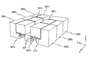
本実施形態では、真空チャンバ300〜300がそれぞれ備えるロードロックチャンバ302も、真空チャンバ300〜300と同様、Y軸方向に並んで配置されるので、一方の列の真空チャンバ300、300がそれぞれ備えるロードロックチャンバ302、及びチャンバ300と、他方の列の真空チャンバ300、300、300がそれぞれ備えるロードロックチャンバ302とは、所定の間隔を隔てて対向している。そして、図2(B)、図3及び図4に示されるように、この対向する両者間に、Y軸方向に延びる断面矩形の搬送空間SPを区画する搬送チャンバ311が設けられている。搬送空間SP内に後述するシャトル搬送系の移動経路が設けられている。なお、図示は省略されているが、搬送チャンバ311の両側壁には、ゲート部に対向する位置に、シャトル10の通路となる開口が形成されている。なお搬送空間SPは、真空チャンバの内部に比べて真空度の低い低真空空間、例えば、大気圧空間に設定することができるから、搬送チャンバ311は必ずしも用いる必要はない。 In the present embodiment, the load lock chamber 302 provided in each of the vacuum chambers 300 2 to 300 6 is also arranged side by side in the Y-axis direction, similarly to the vacuum chambers 300 2 to 300 6 , so the vacuum chambers 300 3 in one row are arranged. , 300 load lock chamber 302 provided 2 respectively, and a chamber 300 1, and the load lock chamber 302 to the vacuum chamber 300 6 in the other row, 300 5, 300 4 is provided respectively to face at a predetermined interval Yes. As shown in FIGS. 2B, 3, and 4, a transport chamber 311 that partitions a transport space SP having a rectangular cross section extending in the Y-axis direction is provided between the two facing each other. A movement path of a shuttle transport system, which will be described later, is provided in the transport space SP. Although not shown, openings on both side walls of the transfer chamber 311 are formed as passages for the shuttle 10 at positions facing the gate portion. Since the transfer space SP can be set to a low vacuum space having a lower degree of vacuum than the inside of the vacuum chamber, for example, an atmospheric pressure space, the transfer chamber 311 is not necessarily used.

露光制御装置380、380、380、380、380は、図2(B)及び図4に示されるように、各ロードロックチャンバ302の上方且つ真空チャンバ300、300、300、300、300の内側の空間に配置された制御ボックス381、381、381、381、381内にそれぞれ収納されている。なお、制御ボックス381、381、381、381、381は、図2(B)に制御ボックス381について代表的に示されるように、実際には、真空チャンバと搬送チャンバ311との間に架設された支持フレーム313の上に載置されている。支持フレーム313は、実際には、床面F上に支持されている。 The exposure control devices 380 2 , 380 3 , 380 4 , 380 5 , 380 6 are arranged above the load lock chamber 302 and in the vacuum chambers 300 2 , 300 3 , 300 as shown in FIG. 2B and FIG. 4 , 300 5 , 300 6 are accommodated in control boxes 381 2 , 381 3 , 381 4 , 381 5 , 381 6 disposed in the space inside. It should be noted that the control boxes 381 2 , 381 3 , 381 4 , 381 5 , 381 6 are actually a vacuum chamber and a transfer chamber 311, as representatively shown for the control box 381 3 in FIG. Is placed on a support frame 313 constructed between the two. The support frame 313 is actually supported on the floor surface F.

次に、計測室60内部の構成について簡単に説明する。計測室60内には、図13(A)に示されるように、XY平面内で2次元移動する計測ステージSTと計測ステージST上に搭載された計測テーブルTBとを有する計測ステージ装置30と、計測システム40と、ウエハW及びシャトル10を搬送する例えば多関節ロボットから成る計測室内搬送系62(図15参照)とが収納されている。計測ステージ装置30には、計測テーブルTBに前述と同様のキネマティックカップリングを介して着脱自在にシャトル10が装着される。そして、計測システム40は、シャトル10に保持されたウエハWに対して所定の計測を行う。   Next, the configuration inside the measurement chamber 60 will be briefly described. In the measurement chamber 60, as shown in FIG. 13A, a measurement stage device 30 having a measurement stage ST that moves two-dimensionally in the XY plane and a measurement table TB mounted on the measurement stage ST, The measurement system 40 and a measurement room transfer system 62 (see FIG. 15) made of, for example, an articulated robot for transferring the wafer W and the shuttle 10 are accommodated. In the measurement stage device 30, the shuttle 10 is detachably attached to the measurement table TB via the same kinematic coupling as described above. Then, the measurement system 40 performs predetermined measurement on the wafer W held on the shuttle 10.

この他、計測室60の内部には、シャトル10を収納可能な複数段の棚を有し、複数のシャトル10を同時保管可能なシャトルストッカ(不図示)が設けられている。本実施形態では、シャトルストッカは、収納されているシャトル10の温調機能をも有している。これに限らず、シャトルの温調装置を、シャトルストッカとは別に設けも良い。なお、ウエハを搬送する搬送系とシャトルを搬送する搬送系とが別々に設けられていても良いが、本実施形態では、説明を簡略化するため、同一の搬送系によりウエハ及びシャトルの搬送が行われるものとする。   In addition, a shuttle stocker (not shown) capable of storing a plurality of shuttles 10 at the same time is provided in the measurement chamber 60. In the present embodiment, the shuttle stocker also has a temperature control function of the shuttle 10 accommodated therein. Not limited to this, a temperature control device for the shuttle may be provided separately from the shuttle stocker. In addition, although the conveyance system which conveys a wafer and the conveyance system which conveys a shuttle may be provided separately, in this embodiment, in order to simplify description, a wafer and a shuttle are conveyed by the same conveyance system. Shall be done.

計測テーブルTBには、シャトル10に形成された前述の複数の円形開口に対応する配置で複数の円形開口が形成されている。計測ステージSTには、複数の円形開口に対応する配置で、複数のピン32が凸設されており、複数のピン32が計測テーブルTBの複数の円形開口内に個別に挿入された状態で、計測テーブルTBが計測ステージST上に配置されている。計測テーブルTBは、計測ステージSTに設けられた駆動系34によって駆動され、所定ストロークで上下動(Z軸方向に移動)可能である。本実施形態では、計測テーブルTBは、シャトル10がキネマティックカップリングを介して装着された状態で、シャトル10の上面が複数のピン32の上端面より所定距離高くなる(複数のピンの上端面がシャトル10の上面から突出しない)図13(A)に示される第1位置と、シャトル10のウエハ載置面(静電チャックの上面)が複数のピン32の上端面より所定距離低くなる(複数のピン32の上端面がシャトル10のウエハ載置面から突出する)図13(B)に示される第2位置との間で、上下動可能である。
なお、計測ステージST上に計測テーブルTBを載置し、計測テーブルTBに対して、複数のピン32を上下動させても良い。
In the measurement table TB, a plurality of circular openings are formed in an arrangement corresponding to the above-described plurality of circular openings formed in the shuttle 10. The measurement stage ST is provided with a plurality of pins 32 in an arrangement corresponding to the plurality of circular openings, and the plurality of pins 32 are individually inserted into the plurality of circular openings of the measurement table TB. A measurement table TB is arranged on the measurement stage ST. The measurement table TB is driven by a drive system 34 provided on the measurement stage ST, and can be moved up and down (moved in the Z-axis direction) with a predetermined stroke. In the present embodiment, the measurement table TB is such that the upper surface of the shuttle 10 is higher than the upper end surfaces of the plurality of pins 32 by a predetermined distance in a state where the shuttle 10 is mounted via the kinematic coupling (the upper end surfaces of the plurality of pins). 13 does not protrude from the upper surface of the shuttle 10) and the wafer placement surface (upper surface of the electrostatic chuck) of the shuttle 10 is lower than the upper end surfaces of the plurality of pins 32 by a predetermined distance (see FIG. 13A). The upper end surfaces of the plurality of pins 32 protrude from the wafer mounting surface of the shuttle 10 and can move up and down between the second positions shown in FIG.
Note that the measurement table TB may be placed on the measurement stage ST, and the plurality of pins 32 may be moved up and down with respect to the measurement table TB.

計測ステージSTは、例えば平面モータから成る計測ステージ駆動系36(図15参照)によってXY平面内で駆動(θz方向の回転を含む)される。計測ステージSTのXY平面内の位置情報は、計測ステージ干渉計38(図15参照)によって計測されている。また、計測テーブルTBの上下方向の位置は、駆動系34が有するエンコーダによって計測されている。計測ステージ装置30の各部の動作は、計測制御装置50によって制御される(図15参照)。   The measurement stage ST is driven (including rotation in the θz direction) in the XY plane by a measurement stage drive system 36 (see FIG. 15) composed of a planar motor, for example. Position information of the measurement stage ST in the XY plane is measured by a measurement stage interferometer 38 (see FIG. 15). The vertical position of the measurement table TB is measured by an encoder included in the drive system 34. The operation of each part of the measurement stage device 30 is controlled by the measurement control device 50 (see FIG. 15).

計測システム40は、図13(A)に示されるように、アライメント検出系ALGと、照射系42aと受光系42bとを有する面位置検出装置AF(図15参照)とを含む。   As shown in FIG. 13A, the measurement system 40 includes an alignment detection system ALG and a surface position detection device AF (see FIG. 15) having an irradiation system 42a and a light receiving system 42b.

本実施形態では、シャトル10上に保持されているウエハ上面には、感応剤(電子線用レジスト)が塗布さているのに対応して、アライメント検出系ALGの検出光として、電子線レジストを感光させない波長の検出ビームが用いられる。アライメント検出系ALGとして、例えばウエハ上に塗布されているレジストを感光させないブロードバンドな検出光束を対象マークに照射し、その対象マークからの反射光により受光面に結像された対象マークの像と不図示の指標(内部に設けられた指標板上の指標パターン)の像とを撮像素子(CCD等)を用いて撮像し、それらの撮像信号を出力する画像処理方式のFIA(Field Image Alignment)系が用いられている。アライメント検出系ALGからの撮像信号は、信号処理装置(不図示)を介して計測制御装置50に供給されるようになっている(図15参照)。なお、アライメント検出系ALGとして、FIA系に限らず、例えばコヒーレントな検出光を対象マークに照射し、その対象マークから発生する2つの回折光(例えば同次数の回折光、あるいは同方向に回折する回折光)を干渉させて検出する回折光干渉型のアライメント検出系を、FIA系に代えて用いても良い。   In the present embodiment, in response to the application of a sensitive agent (electron beam resist) to the upper surface of the wafer held on the shuttle 10, the electron beam resist is exposed as detection light of the alignment detection system ALG. A detection beam having a wavelength that is not allowed is used. For example, the alignment detection system ALG irradiates the target mark with a broadband detection light beam that does not sensitize the resist applied on the wafer, and the image of the target mark formed on the light-receiving surface by the reflected light from the target mark is not detected. An image processing type FIA (Field Image Alignment) system that captures an image of the illustrated index (an index pattern on an index plate provided inside) using an image sensor (CCD or the like) and outputs the imaged signals. Is used. The imaging signal from the alignment detection system ALG is supplied to the measurement control device 50 via a signal processing device (not shown) (see FIG. 15). The alignment detection system ALG is not limited to the FIA system. For example, the target mark is irradiated with coherent detection light, and two diffracted lights generated from the target mark (for example, diffracted light of the same order or in the same direction) are diffracted. A diffracted light interference type alignment detection system that detects by diffracting light) may be used instead of the FIA system.

面位置検出系AFは、照射系42aと受光系42bとを有し、例えば米国特許第5,448,332号明細書等に開示されるものと同様の構成の斜入射方式の多点焦点位置検出系によって構成される。面位置検出系AFの複数の検出点は、被検面上でX軸方向に沿って所定間隔で配置される。本実施形態では、例えば1行M列(Mは検出点の総数)または2行N列(Nは検出点の総数の1/2)の行マトリックス状に配置される。図13(A)中では、図示が省略されているが、複数の検出点は、ウエハWの直径と同程度のX軸方向の長さを有する領域内にほぼ均等に設定されているので、ウエハWをY軸方向に1回スキャンするだけで、ウエハWのほぼ全面でZ軸方向の位置情報(面位置情報)を計測できる。本実施形態では、上述した計測室60内に配置された各部、すなわち計測ステージ装置30、計測システム40、及び計測室内搬送系62等と、計測制御装置50とによって、シャトル10上に保持された露光前のウエハに対する事前計測を行う計測部65が構成されている(図15参照)。   The surface position detection system AF includes an irradiation system 42a and a light receiving system 42b. For example, an oblique incidence type multipoint focal position having the same configuration as that disclosed in US Pat. No. 5,448,332 and the like is used. Consists of a detection system. The plurality of detection points of the surface position detection system AF are arranged at predetermined intervals along the X-axis direction on the surface to be detected. In this embodiment, for example, they are arranged in a row matrix of 1 row and M columns (M is the total number of detection points) or 2 rows and N columns (N is 1/2 of the total number of detection points). Although not shown in FIG. 13A, the plurality of detection points are set almost evenly in a region having a length in the X-axis direction that is about the same as the diameter of the wafer W. The position information (surface position information) in the Z-axis direction can be measured on almost the entire surface of the wafer W only by scanning the wafer W once in the Y-axis direction. In the present embodiment, the components placed in the measurement chamber 60 described above, that is, the measurement stage device 30, the measurement system 40, the measurement chamber conveyance system 62, and the like, and the measurement control device 50 are held on the shuttle 10. A measuring unit 65 that performs pre-measurement on the wafer before exposure is configured (see FIG. 15).

この他、本実施形態に係る露光システム1000は、前述の空間SP内を移動して、露光前のウエハを保持するシャトル10を、計測室60から真空チャンバ300がそれぞれ備えるロードロックチャンバ302に搬送し、露光済みのウエハを保持するシャトル10をロードロックチャンバ302から計測室60に搬送する、シャトルの搬送動作を繰り返し行うシャトル搬送系70(図14参照)を、さらに備えている。シャトル搬送系70は、例えば空間SP内を移動可能な水平多関節ロボットによって構成される。シャトル搬送系70は、マイクロコンピュータ等を含む搬送系制御装置72(図14参照)によって制御される。 In addition, in the exposure system 1000 according to the present embodiment, the shuttle 10 that moves in the space SP described above and holds the wafer before exposure is transferred from the measurement chamber 60 to the load lock chamber 302 included in the vacuum chamber 300 i. A shuttle transport system 70 (see FIG. 14) is further provided for repeatedly performing the shuttle transport operation for transporting the shuttle 10 that holds the exposed wafer from the load lock chamber 302 to the measurement chamber 60. The shuttle transfer system 70 is configured by a horizontal articulated robot that can move in the space SP, for example. The shuttle transport system 70 is controlled by a transport system control device 72 (see FIG. 14) including a microcomputer or the like.

図14には、露光システム1000の制御系の構成がブロック図にて示されている。露光システム1000の制御系は、露光システム1000の全体を統括的に制御するワークステーション等から成る主制御装置100と、主制御装置100の配下にある計測制御装置50、5つの露光制御装置380〜380、及び搬送系制御装置72とを備えている。 FIG. 14 is a block diagram showing the configuration of the control system of the exposure system 1000. The control system of the exposure system 1000 includes a main control device 100 composed of a workstation and the like that collectively control the entire exposure system 1000, a measurement control device 50 under the control of the main control device 100, and five exposure control devices 380 2. ˜380 6 and a transport system controller 72.

図15には、図14の制御系を構成する計測制御装置50の入出力関係がブロック図にて示されている。計測制御装置50は、マイクロコンピュータ等を含み、計測室60内に設けられた図15に示される各部を制御する。   FIG. 15 is a block diagram showing the input / output relationship of the measurement control device 50 constituting the control system of FIG. The measurement control device 50 includes a microcomputer and controls each unit shown in FIG. 15 provided in the measurement chamber 60.

図16には、図14の制御系を構成する5つの露光制御装置380(i=2〜6)の入出力関係がブロック図にて示されている。露光制御装置380は、マイクロコンピュータ等を含み、露光室301内に設けられた図16に示される各部を制御する。 FIG. 16 is a block diagram showing the input / output relationship of the five exposure control devices 380 i (i = 2 to 6) constituting the control system of FIG. The exposure control device 380 i includes a microcomputer and controls each unit shown in FIG. 16 provided in the exposure chamber 301 i .

次に、計測室60内で行われる事前準備作業の一例について、図17(A)のフローチャートに基づいて説明する。以下で説明する各ステップの処理は、計測制御装置50の制御下で行われるが、以下では、説明の簡略化のため、計測制御装置50に関する説明は特に必要な場合を除き省略する。   Next, an example of the preparatory work performed in the measurement chamber 60 will be described based on the flowchart of FIG. The processing of each step described below is performed under the control of the measurement control device 50. However, for the sake of simplification of description, the description regarding the measurement control device 50 is omitted unless particularly necessary.

前提として、シャトルストッカ(不図示)には、複数のシャトル10が保管されているものとする。また、露光前のウエハは、計測室60にインラインにて接続されているC/D9000側のウエハ搬送系によって基板受け渡し部に載置されているものとする。   It is assumed that a plurality of shuttles 10 are stored in a shuttle stocker (not shown). Further, it is assumed that the wafer before exposure is placed on the substrate transfer section by a wafer transfer system on the C / D 9000 side connected inline to the measurement chamber 60.

ステップS102において、シャトルストッカ(不図示)に保管されているシャトル10が、計測テーブルTBに装着される。具体的には、シャトルストッカ(不図示)に保管されているシャトル10が、計測室内搬送系62により、シャトルストッカからウエハ交換位置にある計測ステージST上で前述の第2位置に位置している計測テーブルTBの上方に搬送された後、下方に駆動されて計測テーブルTBにキネマティックカップリングを介して装着される。   In step S102, the shuttle 10 stored in a shuttle stocker (not shown) is mounted on the measurement table TB. Specifically, the shuttle 10 stored in the shuttle stocker (not shown) is positioned at the second position on the measurement stage ST at the wafer exchange position from the shuttle stocker by the measurement chamber transport system 62. After being conveyed above the measurement table TB, it is driven downward and attached to the measurement table TB via a kinematic coupling.

次のステップS104では、計測室内搬送系62により基板受け渡し部にある露光前のウエハ(便宜上、ウエハWとする)が、計測ステージSTの複数のピン32に渡される。このとき、計測テーブルTBは第2位置にあり、この状態で、ウエハWは、回転位置ずれ及び中心位置ずれが調整された状態で、複数のピン32の上に載置される。 In the next step S104, the wafer before exposure in the substrate transfer unit by the measuring chamber conveying system 62 (for convenience, the wafer W 1) is passed to a plurality of pins 32 of the measuring stage ST. At this time, the measurement table TB is in a second position, in this state, the wafer W 1 is in a state where the rotational position displacement and displacement between the center positions is adjusted is placed on the plurality of pins 32.

次のステップS106では、ウエハWをシャトル10に保持させる。具体的には、計測テーブルTBを第1位置まで上方に駆動することで、ウエハWをシャトル10の静電チャック上に載置し、その後、静電チャックによるウエハの吸着を開始する。なお、シャトル10には、静電チャックに接続された接続端子が設けられ、また、計測テーブルTBには、不図示の電力供給源に接続されたテーブル側端子が設けられており、計測テーブルTBにシャトル10がキネマティックカップリングを介して装着された時に、接続端子とテーブル側端子とが接続され、電力供給源から静電チャックに電力が供給可能になる。 In the next step S106, to hold the wafer W 1 to the shuttle 10. Specifically, the measurement table TB by driving upwards to the first position, to place the wafer W 1 on the electrostatic chuck of the shuttle 10, then, starts the adsorption of the wafer by the electrostatic chuck. The shuttle 10 is provided with a connection terminal connected to the electrostatic chuck, and the measurement table TB is provided with a table side terminal connected to a power supply source (not shown), and the measurement table TB. When the shuttle 10 is mounted via the kinematic coupling, the connection terminal and the table side terminal are connected, and power can be supplied from the power supply source to the electrostatic chuck.

次のステップS108では、ウエハWのシャトル10に対する概略(ラフ)位置計測を行う。具体的には、最初に、ウエハWのサーチアライメントを行った後、シャトル10に設けられた基準マーク(不図示)の位置情報を計測し、シャトル10(基準マーク)に対するウエハWの相対位置情報を求める。 In the next step S108, it performs an outline (rough) position measurement with respect to the shuttle 10 of the wafer W 1. More specifically, first, after the search alignment of the wafer W 1, and measures the positional information of the reference mark provided on the shuttle 10 (not shown), the relative wafer W 1 for the shuttle 10 (reference marks) Find location information.

サーチアライメントに際し、例えば、ウエハWの中心に関してほぼ対称に周辺部に位置する少なくとも2つのサーチアライメントマーク(以下、サーチマークと称する)が検出対象となる。計測制御装置50は、計測ステージ駆動系36による計測ステージSTの駆動を制御して、それぞれのサーチマークをアライメント検出系ALGの検出領域(検出視野)内に位置決めしつつ、計測ステージ干渉計38による計測情報を取得し、アライメント検出系ALGを用いてウエハWに形成されたサーチマークを検出した時の検出信号と、計測ステージ干渉計38による計測情報とに基づいて、各サーチマークの位置情報を求める。 Upon search alignment, for example, at least two search alignment marks located on the periphery portion substantially symmetrical with respect to the center of the wafer W 1 (hereinafter, referred to as search mark) is detected. The measurement control device 50 controls the driving of the measurement stage ST by the measurement stage drive system 36 and positions each search mark in the detection region (detection field of view) of the alignment detection system ALG while using the measurement stage interferometer 38. acquires measurement information, a detection signal upon detection of search mark formed on the wafer W 1 by using the alignment detection system ALG, based on the measurement information by the measuring stage interferometer 38, the position information of each search mark Ask for.

より具体的には、計測制御装置50は、信号処理装置(不図示)から出力されるアライメント検出系ALGの検出結果(検出信号から求まるアライメント検出系ALGの検出中心(指標中心)と各サーチマークとの相対位置関係)と、各サーチマーク検出時の計測ステージ干渉計38の計測値とに基づいて、2つのサーチマークの基準座標系上の位置座標を求める。ここで、基準座標系は、計測ステージ干渉計38の測長軸によって規定される直交座標系である。   More specifically, the measurement control device 50 detects the detection result of the alignment detection system ALG output from a signal processing device (not shown) (the detection center (index center) of the alignment detection system ALG obtained from the detection signal) and each search mark. Relative position) and the measurement value of the measurement stage interferometer 38 when each search mark is detected, the position coordinates of the two search marks on the reference coordinate system are obtained. Here, the reference coordinate system is an orthogonal coordinate system defined by the measurement axis of the measurement stage interferometer 38.

しかる後、計測制御装置50は、サーチマークと同様の手順で、シャトル10上に設けられた複数の基準マークの基準座標系上の位置座標を求める。そして、2つのサーチマークの位置座標と複数の基準マークの位置座標とに基づいて、ウエハWのシャトル10に対する相対位置を求める。ここで、概略位置計測と読んでいるのは、アライメント検出系ALGによるマークの位置座標の検出精度が、露光直前に行われる、反射電子の検出によるアライメントマークの位置座標の検出精度に比べて低いからである。これにより、ウエハWのシャトル10に対する概略位置計測が終了する。なお、ウエハWは、実際には回転位置ずれ及び中心位置ずれが調整された状態でシャトル10上にロードされるので、ウエハWの中心位置ずれは無視できるほど小さく、残留回転誤差は非常に小さい。 Thereafter, the measurement control device 50 obtains the position coordinates on the reference coordinate system of the plurality of reference marks provided on the shuttle 10 in the same procedure as the search mark. Then, based on the position coordinates of the position coordinates and a plurality of reference marks of the two search marks to determine the relative position with respect to the shuttle 10 of the wafer W 1. Here, what is read as approximate position measurement is that the detection accuracy of the position coordinates of the mark by the alignment detection system ALG is lower than the detection accuracy of the position coordinates of the alignment mark by detection of reflected electrons performed immediately before exposure. Because. Accordingly, the approximate position measuring relative the shuttle 10 of the wafer W 1 is completed. Incidentally, the wafer W 1, since in fact loaded on the shuttle 10 in a state where the rotational position deviation and the center position deviation is adjusted, the more central position deviation of the wafer W 1 is negligibly small, the residual rotation error is very Small.

ステップS108のウエハWのシャトル10に対する概略位置計測が終了すると、ステップS110に進み、ウエハWのフラットネス計測(表面の凹凸の計測)が行われる、このフラットネス計測は、計測ステージSTをY軸方向に移動させながら、面位置検出装置AFの計測情報と計測ステージ干渉計38の計測情報とを所定のサンプリング間隔で取り込むことで行われる。ここで、ウエハのフラットネスの計測を行うのは、電子ビーム露光装置では、ウエハ表面の凹凸に起因してウエハのXY平面内の位置計測誤差(横ずれ)が生じるので、露光の際にこの位置計測誤差を補正する必要があるからである。この位置計測誤差は、ウエハのフラットネス情報(ウエハ座標系上のXY座標位置(X,Y)に応じたZ位置の情報Z(X,Y))に基づいて簡単に演算で求めることができる。なお、サーチアライメントにより、ウエハの回転ずれの情報は既知なので、ウエハ座標系と前述の基準座標系との関係は、簡単に求めることができる。 When coarse position measurement is finished for the shuttle 10 of the wafer W 1 in step S108, the process proceeds to step S110, flatness measurement of the wafer W 1 (Measurement of surface irregularities) is carried out, the flatness measurement, the measuring stage ST This is performed by capturing the measurement information of the surface position detector AF and the measurement information of the measurement stage interferometer 38 at a predetermined sampling interval while moving in the Y-axis direction. Here, the wafer flatness is measured in the electron beam exposure apparatus because a position measurement error (lateral deviation) in the XY plane of the wafer occurs due to the unevenness of the wafer surface. This is because the measurement error needs to be corrected. This position measurement error can be easily obtained by calculation based on wafer flatness information (Z position information Z (X, Y) corresponding to XY coordinate position (X, Y) on the wafer coordinate system). . Since the information on the rotational deviation of the wafer is known by the search alignment, the relationship between the wafer coordinate system and the reference coordinate system can be easily obtained.

ステップS110のフラットネス計測が終了すると、ステップS112において、ウエハWを保持したシャトル10が、計測室内搬送系62によって、上方に駆動され、キネマティックカップリングを解除して計測テーブルTB上から取り外された後、計測室60の空間SPとの境界部に設けられているシャトル受け渡し部のロード側シャトル載置部に載置される。これにより、計測室60内における事前計測動作(S108、S110)を含む事前準備作業が終了する。なお、計測テーブルTBからシャトル10が取り外された後も、シャトル10の静電チャックは、残留電荷によりウエハWを保持することが可能である。また、シャトル10に内部電源を設け、計測テーブルTBからシャトル10が取り外された後は、この内部電源から静電着チャックに電力を供給しても良い。 When flatness measurement step S110 is finished, in step S112, the shuttle 10 holding the wafer W 1 is, by measuring the indoor transport system 62 is driven upwardly, detached from the measurement table TB to release the kinematic coupling After that, it is placed on the load-side shuttle placement portion of the shuttle delivery portion provided at the boundary with the space SP of the measurement chamber 60. Thereby, the preliminary preparation work including the preliminary measurement operation (S108, S110) in the measurement chamber 60 is completed. Even after the shuttle 10 is detached from the measurement table TB, the electrostatic chuck of the shuttle 10 is capable of holding the wafer W 1 by the residual charge. Further, the shuttle 10 may be provided with an internal power supply, and after the shuttle 10 is removed from the measurement table TB, power may be supplied from the internal power supply to the electrostatic chuck.

次に、計測室60内で行われる露光済みのウエハのアンロード作業について、図17(B)のフローチャートに基づいて説明する。以下で説明する各ステップの処理は、計測制御装置50の制御下で行われるが、以下では、説明の簡略化のため、計測制御装置50に関する説明は特に必要な場合を除き省略する。前提として、露光済みのウエハを保持するシャトルが、シャトル受け渡し部のアンロード側シャトル載置部に載置されているものとする。   Next, the unloading operation of the exposed wafer performed in the measurement chamber 60 will be described based on the flowchart of FIG. The processing of each step described below is performed under the control of the measurement control device 50. However, for the sake of simplification of description, the description regarding the measurement control device 50 is omitted unless particularly necessary. As a premise, it is assumed that the shuttle holding the exposed wafer is placed on the unload-side shuttle placement unit of the shuttle delivery unit.

ステップS122において、露光済みのウエハ(便宜上、ウエハWとする)を保持するシャトル10が、計測テーブルTBに装着される。具体的には、ウエハWを保持するシャトル10が、計測室内搬送系62により、シャトル受け渡し部のアンロード側シャトル載置部からウエハ交換位置にある計測ステージST上で前述の第1位置に位置している計測テーブルTBの上方に搬送された後、下方に駆動されて計測テーブルTBにキネマティックカップリングを介して装着される。 In step S122, the exposed wafer (for convenience, the wafer W 0) shuttle 10 for holding the can, is attached to the measuring table TB. Specifically, the shuttle 10 holding the wafer W 0 is moved from the unload-side shuttle placement part of the shuttle delivery part to the above-described first position on the measurement stage ST at the wafer exchange position by the measurement room transfer system 62. After being conveyed above the measurement table TB that is positioned, it is driven downward and attached to the measurement table TB via a kinematic coupling.

次のステップS124では、シャトル10からウエハWを離脱させる(取り外す)。具体的には、シャトル10の静電チャックによるウエハWの吸着を解除し、計測テーブルTBを第2位置まで下方に駆動する。これにより、複数のピン32によってウエハWが下方から全体的に押し上げられ、ウエハWをシャトル10から容易に離脱させることができる。なお、残留電荷に起因してウエハWがシャトル10から離脱させ難い場合には、ウエハWに超音波を印可させたり、または各種除電対策を行いながらウエハを離脱させることもできる。 In the next step S124, the disengaging from the shuttle 10 to the wafer W 0 (removed). Specifically, the suction of the wafer W 0 by the electrostatic chuck of the shuttle 10 is released, and the measurement table TB is driven downward to the second position. Thus, the wafer W 0 is totally pushed up from below by a plurality of pins 32, the wafer W 0 can be easily detached from the shuttle 10. In the case where the wafer W 0 due to residual charge is less likely to disengage from the shuttle 10 can in the wafer W 0 or is applied ultrasound, or also disengaging the wafer while various neutralization measures.

次のステップS126では、複数のピン32によって支持されているウエハWが、計測室内搬送系62により計測テーブルTB上から搬出され前述の基板受け渡し部に載置される。 In the next step S126, the wafer W 0 which is supported by a plurality of pins 32, the measuring chamber conveying system 62 is carried out from the measurement table TB is placed on the substrate transfer unit described above.

次のステップ128では、シャトル10が、計測室内搬送系62によって、上方に駆動され、キネマティックカップリングを解除して計測テーブルTB上から取り外された後、シャトルストッカの空いている収納棚に収納される。これにより、計測室60内における露光済みのウエハのアンロード作業が終了する。シャトルストッカ内に収納されたシャトル10は、次に取り出されるまで、シャトルストッカ内に保管されるが、この保管中に所定の温度に調整(冷却)される。   In the next step 128, the shuttle 10 is driven upward by the measurement room transport system 62, released from the measurement table TB after releasing the kinematic coupling, and then stored in an empty storage shelf of the shuttle stocker. Is done. Thereby, the unloading operation of the exposed wafer in the measurement chamber 60 is completed. The shuttle 10 accommodated in the shuttle stocker is stored in the shuttle stocker until it is next taken out, and is adjusted (cooled) to a predetermined temperature during the storage.

次に、露光システム1000によるウエハに対する処理の流れについて説明する。以下で説明する処理は、計測制御装置50及び露光制御装置380〜380、並びに搬送系制御装置72により、これらの制御装置を統括的に管理する主制御装置100の管理の下で行われるが、以下では、これらの制御装置に関する説明は特に必要な場合を除き、省略する。また、実際には、各露光室301内には、露光ユニット310が、各2つ収容され、これに対応してロードロックチャンバ302(ロードロック室)も2つ設けられているが、以下では、説明の便宜上、各露光室301内には、露光ユニット310が1つ収容され、ロードロックチャンバも真空チャンバに1つだけ設けられているものとする。すなわち、真空チャンバ(露光室)と、露光ユニットと、ロードロックチャンバ(ロードロック室)とが、互いに1:1対応であるものとする。 Next, a processing flow for the wafer by the exposure system 1000 will be described. The processing described below is performed by the measurement control device 50, the exposure control devices 380 2 to 380 6 , and the transport system control device 72 under the management of the main control device 100 that manages these control devices in an integrated manner. However, in the following, description regarding these control devices will be omitted unless particularly required. In practice, two exposure units 310 are accommodated in each exposure chamber 301 i , and two load lock chambers 302 (load lock chambers) are provided correspondingly. Then, for convenience of explanation, it is assumed that each exposure chamber 301 i contains one exposure unit 310 and only one load lock chamber is provided in the vacuum chamber. That is, the vacuum chamber (exposure chamber), the exposure unit, and the load lock chamber (load lock chamber) have a one-to-one correspondence with each other.

露光システム1000による処理が開始されるのに先立って、C/D9000内の搬送系(例えば多関節型のロボット)により、電子線レジストが塗布された露光前のウエハが計測室60とC/D9000との境界部分に設けられた基板受け渡し部上に載置される。C/D9000内では、ウエハに対する電子線レジスト塗布処理を含む一連の処理が順次繰り返し行われ、ウエハが順次基板受け渡し部上に載置される。   Prior to the start of the processing by the exposure system 1000, the wafer before the exposure with the electron beam resist applied to the measurement chamber 60 and the C / D 9000 is transferred by a transfer system (for example, an articulated robot) in the C / D 9000. Is placed on a substrate transfer portion provided at a boundary portion between the two. Within the C / D 9000, a series of processes including an electron beam resist coating process on the wafer are sequentially repeated, and the wafers are sequentially placed on the substrate transfer unit.

まず、計測室60内で、前述したステップS102〜ステップS112の処理が行われる。これにより、ウエハのシャトルに対する概略位置計測及びフラットネス計測が終了した露光前のウエハWを保持するシャトル10が、シャトル受け渡し部のロード側シャトル載置部に載置されることになる。 First, in the measurement chamber 60, the process of step S102-step S112 mentioned above is performed. Thus, the shuttle 10 to coarse position measurement and flatness measurement of wafer shuttles to hold the wafer W 1 before exposure was completed, will be placed on the load side shuttle mounting portion of the shuttle transfer unit.

次いで、シャトル搬送系70により、シャトル受け渡し部のロード側シャトル載置部から露光前のウエハWを保持するシャトル10が、主制御装置100によって指定された露光室301に対応するロードロックチャンバ302の前方に搬送された後、その指定された露光室301内の露光済みのウエハWを保持するシャトル10と交換される。この場合、主制御装置100は、その時点でウエハに対する露光処理が終了している露光室301があれば、その露光室301を指定し、露光処理が終了している露光室がなければ、最も早いタイミングで露光処理が終了する予定の露光室301を指定する。ここでは、一例として、最も早いタイミングで露光処理が終了する予定の露光室301が指定されるものとする。 Next, the shuttle 10 that holds the wafer W 1 before exposure from the load-side shuttle placement unit of the shuttle transfer unit by the shuttle transfer system 70 is loaded into the load lock chamber corresponding to the exposure chamber 301 i specified by the main controller 100. after being transported to the front of the 302, it is replaced with the shuttle 10 to hold the exposed wafer W of the designated exposure chamber 301 i. In this case, main controller 100 designates exposure chamber 301 i if there is an exposure chamber 301 i for which the exposure processing for the wafer has been completed at that time, and if there is no exposure chamber for which the exposure processing has been completed. The exposure chamber 301 i where the exposure process is scheduled to end at the earliest timing is designated. Here, as an example, it is assumed that the exposure chamber 301 i where the exposure process is scheduled to end at the earliest timing is designated.

以下、シャトル交換動作、すなわちシャトルと一体でのウエハの交換動作について図面に基づいて具体的に説明する。まず、シャトル受け渡し部のロード側シャトル載置部から搬出されたウエハWを保持するシャトル10は、図18に示されるように、露光室301が内部に形成された真空チャンバ300のロードロックチャンバ302の前方(この場合、+Y側)の位置までシャトル搬送系70によって搬送される。このとき、露光室301内では、ウエハWの露光が行われている。なお、以下の説明では、「ウエハWを保持するシャトル」を、便宜上、「シャトル10」と表記し、「ウエハWを保持するシャトル」を、「シャトル10」と表記する。また、これに併せて、以下の説明で用いる図19〜図27においては、ウエハの図示が省略されている。 Hereinafter, a shuttle exchange operation, that is, a wafer exchange operation integrated with the shuttle will be specifically described with reference to the drawings. First, the shuttle 10 holding the wafer W 1 taken out from the load side shuttle mounting portion of the shuttle transfer unit, as shown in FIG. 18, the vacuum chamber 300 i load the exposure chamber 301 i formed therein It is transported by the shuttle transport system 70 to a position in front of the lock chamber 302 (in this case, the + Y side). In this case, in the exposure chamber 301 i, the exposure of the wafer W 0 is performed. In the following description, the "shuttle for holding a wafer W 1", for convenience, referred to as "shuttle 10 1", the "shuttle for holding a wafer W 0", referred to as "shuttle 10 0". In addition to this, in FIGS. 19 to 27 used in the following description, illustration of the wafer is omitted.

ウエハWの露光が終了すると、図18中に下向きの白抜き矢印で示されるように、真空チャンバ300のロードロックチャンバ302に設けられた外側(大気側)ゲートバルブ302bが開けられた後、図19中に黒矢印で示されるように、シャトル10がシャトル搬送系70によってロードロック室304内に搬入される。次に、図19中に上向きの白抜き矢印で示されるように、外側(大気側)ゲートバルブ302bが閉じられた後、ロードロック室304内の真空引きが開始される。 When the exposure of the wafer W 0 is completed, as indicated by a downward white arrow in FIG. 18, the outer in the load-lock chamber 302 of the vacuum chamber 300 i (atmosphere side) after the gate valve 302b is opened , as indicated by the black arrow in FIG. 19, the shuttle 10 1 is carried into the load lock chamber 304 by the shuttle transfer system 70. Next, as shown by the upward white arrow in FIG. 19, after the outer (atmosphere side) gate valve 302b is closed, the evacuation of the load lock chamber 304 is started.

シャトル搬送系70は、ロードロック室304内にシャトル10を搬入後、次の露光前のウエハを保持するシャトルをシャトル受け渡し部から別のロードロック室内に搬入する動作、又は別の露光済みのウエハを保持するシャトルを別のロードロック室から搬出し、シャトル受け渡し部に搬送する動作など(以下、別の動作と称する)に従事する。 Shuttle transfer system 70, after carrying the shuttle 10 1 into the load lock chamber 304, the operation of carrying the shuttle for holding a wafer before the next exposure from the shuttle transfer unit to another load lock chamber, or another exposed Engage in an operation (hereinafter referred to as another operation) of unloading the shuttle holding the wafer from another load lock chamber and transporting it to the shuttle delivery section.

そして、ロードロック室304内が露光室301と同程度の高真空状態に達すると、図20中に下向きの白抜き矢印で示されるように、ロードロックチャンバ302に設けられた内側(真空側)ゲートバルブ302cが開けられた後、露光室301内部の露光室内搬送系312によって、シャトル10が露光室301内のシャトルキャリア306の下段の収納棚に収納される。このときシャトルキャリア306は、図20に示されるように、下段の収納棚の高さが、ロードロック室304の開口に一致する第1の状態(第1位置)にある。このときの、シャトル10の位置を、便宜上、搬出入位置と称する。このとき、シャトル10上のウエハWに対する露光が続行されている。なお、図18〜図27では、シャトルの位置をわかり易くするため、シャトルキャリア306は、仮想線(二点鎖線)にて簡略化して示されている。 When the inside of the load lock chamber 304 reaches a high vacuum state similar to that of the exposure chamber 301 i , the inner side (vacuum side) provided in the load lock chamber 302 as shown by a downward white arrow in FIG. ) after the gate valve 302c is opened, the exposure chamber 301 i inside the exposure chamber transport system 312, the shuttle 10 1 is housed in the lower storage rack of the shuttle carrier 306 in the exposure chamber 301 i. At this time, as shown in FIG. 20, the shuttle carrier 306 is in a first state (first position) in which the height of the lower storage shelf coincides with the opening of the load lock chamber 304. At this time, the position of the shuttle 10 1, for convenience, referred to as loading and unloading position. In this case, exposure of wafer W 0 on the shuttle 10 0 is continued. 18 to 27, the shuttle carrier 306 is shown in a simplified manner with a virtual line (two-dot chain line) for easy understanding of the position of the shuttle.

次いで、図21中に白抜き矢印で示されるように、シャトルキャリア306は、第1位置から第1の距離下方の第2位置まで下降する。これにより、シャトルキャリア306は、上段の収納棚の高さが、ロードロック室304の開口に一致する第2の状態となる。このとき、シャトル10上のウエハWに対する露光が続行されているので、シャトルキャリア306は、露光が終了するまで、第2の状態を維持する。すなわち、シャトル10は、搬出入位置の下方の第1待機位置で待機する。 Next, as indicated by a hollow arrow in FIG. 21, the shuttle carrier 306 descends from the first position to the second position below the first distance. As a result, the shuttle carrier 306 enters a second state in which the height of the upper storage shelf matches the opening of the load lock chamber 304. At this time, since the exposure of wafer W 0 on the shuttle 10 0 is continued, the shuttle carrier 306, until the exposure is completed, maintaining the second state. That is, the shuttle 10 1 waits at the first waiting position below the loading and unloading position.

そして、露光が終了すると、露光室内搬送系312により、シャトル10が、微動ステージ322bから取り外され、図21中に黒矢印で示されるようにロードロックチャンバ302側(+Y側)に向かって搬送され、シャトルキャリア306の上段の収納棚に収納される。これにより、シャトルキャリア306の上下の収納棚にそれぞれ収納された、シャトル10とシャトル10とが、図22に示されるように、上下に重なった状態となる。なお、微動ステージ322bからシャトル10が取り外されるのに先立って、第2計測系25(図16参照)の計測情報に基づく、微動ステージ322bの6自由度方向の位置、姿勢のフィードバック制御が、露光制御装置380によって開始され、次に第1計測系20(図16参照)の計測情報に基づく、シャトルと一体の微動ステージ322bの位置制御が開始されるまでの間、微動ステージ322bの6自由度方向の位置、姿勢は所定の基準状態に維持される。 When the exposure ends, the exposure chamber transport system 312, the shuttle 10 0, removed from fine movement stage 322b, toward the load lock chamber 302 side (+ Y side) as indicated by the black arrow in FIG. 21 conveyed And stored in the upper storage shelf of the shuttle carrier 306. Thus, it housed respectively above and below the storage rack of the shuttle carrier 306, shuttle 10 0 and the shuttle 10 1, as shown in FIG. 22, a state of vertically overlapping. In advance to the shuttle 10 0 is removed from the fine movement stage 322b, based on the measurement information of the second measurement system 25 (see FIG. 16), in directions of six degrees of freedom position of the fine moving stage 322b, the feedback control of the posture, initiated by the exposure control unit 380 i, then based on the first measurement information of the measurement system 20 (see FIG. 16), until the position control of the fine movement stage 322b of the shuttle and integral is started, the fine movement stage 322b 6 The position and orientation in the direction of freedom are maintained in a predetermined reference state.

次いで、図22中に白抜き矢印で示されるように、シャトルキャリア306が、上方に第1の距離移動し、前述の第1の状態(第1位置)に戻る。すなわち、このシャトルキャリア306の上昇動作により、シャトル10とシャトル10とを上方に、第1の距離移動させて、シャトル10を搬出入位置の上方の第2待機位置へ位置させるとともにシャトル10を搬出入位置へ位置させる。 Next, as indicated by a hollow arrow in FIG. 22, the shuttle carrier 306 moves upward by a first distance and returns to the first state (first position) described above. That is, the shuttle by upward movement of the shuttle carrier 306, upward and shuttle 10 1 and the shuttle 10 0, is moved a first distance, along with positioning the shuttle 10 0 to the second standby position above the loading and unloading position 101 Position 1 to the loading / unloading position.

次いで、露光室内搬送系312により、シャトル10がシャトルキャリア306から取り出され、図23中に黒矢印で示されるように粗微動ステージ322の上方に向かって搬送され、微動ステージ322bに装着される(図24参照)。このとき、前述の如く、微動ステージ322bの6自由度方向の位置、姿勢は基準状態に維持されているので、シャトル10を、キネマティックカップリングを介して微動ステージ322bに装着するだけで、電子ビーム照射装置330(電子光学系)とシャトル10との位置関係が所望の位置関係となる。そして、先に説明した簡略アライメント計測の結果を考慮して、微動ステージの322bの位置を微調整することで、微動ステージ322bに装着されたシャトル10上のウエハWに形成された複数(例えば100個)のショット領域のそれぞれに対応してスクライブライン(ストリートライン)に形成された少なくとも各1つのアライメントマークに対して、電子光学系から電子ビームを確実に照射することが可能となる。したがって、少なくとも各1つのアライメントマークからの反射電子が反射電子検出系で検出され、ウエハWの全点アライメント計測が行われ、この全点アライメント計測の結果に基づいて、ウエハW上の複数のショット領域に対し、電子ビーム照射装置330を用いた露光が開始される。 Then, the exposure chamber transport system 312, the shuttle 10 1 is taken out from the shuttle carrier 306 is transported upward in the coarse and fine movement stage 322 as indicated by the black arrow in FIG. 23, is mounted on the fine movement stage 322b (See FIG. 24). At this time, as described above, directions of six degrees of freedom position of the fine moving stage 322b, since the posture is maintained at the reference state, the shuttle 10 1, only attached to the fine movement stage 322b via the kinematic coupling, electronic positional relationship of the beam irradiation device 330 (electro-optical system) and the shuttle 10 1 has a desired positional relationship. A plurality considering the results of the previously-described simplified alignment measurement, the position of 322b of the fine movement stage by the fine adjustment, which are formed on the wafer W 1 on the shuttle 10 1 mounted on the fine movement stage 322b ( For example, the electron optical system can reliably irradiate at least one alignment mark formed on a scribe line (street line) corresponding to each of 100 shot areas. Therefore, the reflected electrons from at least one each of the alignment mark is detected by the reflected electron detection system, all points alignment measurement of the wafer W 1 is performed, based on the result of this all points alignment measurement, a plurality of the wafer W 1 The exposure using the electron beam irradiation apparatus 330 is started for the shot area.

上記の全点アライメント計測及び露光と並行して、シャトル10の前述のシャトル受け渡し部のアンロード側シャトル載置部への搬送動作(シャトルの回収動作)が、以下の手順で行われる。 In parallel with all points alignment measurement and exposure of the shuttle 10 0 of the aforementioned shuttle transfer portion of the transfer operation to the unload side shuttle mounting unit (recovery operation of the shuttle) is performed in the following procedure.

すなわち、まず、シャトルキャリア306が、図24に白抜き矢印で示されるように、第1の距離下方に移動して、再び第2の状態となる。これにより、図25に示されるように、シャトル10が収納されたシャトルキャリア306の上段の収納棚が、ロードロック室304の開口と同じ高さに位置する。 That is, first, as indicated by the white arrow in FIG. 24, the shuttle carrier 306 moves downward by the first distance and enters the second state again. Thus, as shown in FIG. 25, the upper storage rack of the shuttle carrier 306 that shuttle 10 0 is accommodated is positioned at the same height as the opening of the load lock chamber 304.

次いで、露光室内搬送系312により、シャトル10がシャトルキャリア306から取り出され、図25中に黒矢印で示されるように、ロードロック室304内へ向けて搬送され、シャトル10がロードロック室304内に搬入された時点で、真空側のゲートバルブ302cが閉じられる(図26中の白抜き矢印参照)。 Then, the exposure chamber transport system 312, the shuttle 10 0 is removed from the shuttle carrier 306, as indicated by the black arrow in FIG. 25, is conveyed toward the load lock chamber 304, the shuttle 10 0 loadlock chamber When it is carried into 304, the vacuum-side gate valve 302c is closed (see the white arrow in FIG. 26).

このとき、シャトル搬送系70は、前述した別の動作を一旦終了して真空チャンバ300が備えるロードロックチャンバ302の前に移動している。なお、シャトル搬送系70が、別の動作を継続中であった場合、例えば露光室301内でのウエハWの露光が終了した時点で、主制御装置100は、直ちにその別の動作を一時的に中断させ、真空チャンバ300が備えるロードロックチャンバ302の前に移動させても良い。 At this time, the shuttle transport system 70 once completes the other operations described above and moves in front of the load lock chamber 302 included in the vacuum chamber 300 i . When the shuttle transfer system 70 is continuing another operation, for example, when the exposure of the wafer W 0 in the exposure chamber 301 i is completed, the main controller 100 immediately performs the other operation. It may be temporarily interrupted and moved in front of the load lock chamber 302 included in the vacuum chamber 300 i .

次いで、図27中に下向きの白抜き矢印で示されるように、大気側のゲートバルブ302bが開けられた後、シャトル搬送系70によりシャトル10がロードロック室304から取り出されて、回収される。露光制御装置380は、ゲートバルブ302bを開けるのと前後して、図27中に上向きの白抜き矢印で示されるように、第2状態にあるシャトルキャリア306を、第1の距離上向きに駆動して第1状態に戻す。なお、シャトル10が取り出された後、ゲートバルブ302bは、閉じられる。 Next, as shown by a downward white arrow in FIG. 27, after the gate valve 302b of the air side is opened, by the shuttle transfer system 70 shuttles 10 0 is taken out from the load lock chamber 304, is recovered . The exposure control device 380 i drives the shuttle carrier 306 in the second state upward by a first distance as shown by the upward white arrow in FIG. 27 before and after opening the gate valve 302b. To return to the first state. Incidentally, after the shuttle 10 0 has been removed, the gate valve 302b is closed.

次いで、回収されたシャトル10は、シャトル搬送系70により、直ちに、シャトル受け渡し部のアンロード側シャトル載置部へ戻される。この戻されたシャトル10は、計測室内搬送系62によって、ウエハ交換のため、計測テーブルTBに向けて搬送される。以後、計測室60内では前述した処理が繰り返し行われ、主制御装置100により露光室の指定がなされる度に、シャトル搬送系70によるシャトルの搬送、及び指定された露光室301でのシャトルの交換及び露光処理動作が繰り返し行われる。 Then, the recovered shuttle 10 0, by the shuttle transfer system 70, immediately returned to the unload side shuttle mounting portion of the shuttle transfer unit. The shuttle 10 0 returned is by the measurement chamber conveying system 62, for wafer exchange, is conveyed toward the measurement table TB. Thereafter, the inside measurement chamber 60 is repeated the process described above, each time the specified exposure chamber by the main controller 100 is performed, the conveyance of the shuttle by the shuttle transfer system 70, and designated the exposure chamber 301 i shuttle Exchange and exposure processing operations are repeated.

なお、シャトル10のロードロック室304から取り出すためのゲートバルブ302bの開放と前後して、シャトルキャリア306を、第1の状態(第1位置)に戻すものとしたが、これに限らず、第2の状態にあるシャトルキャリア306をそのままにしても良い。この場合には、露光室301内でのシャトルの交換に際して、シャトルキャリア306の第1の状態と第2の状態との設定が上の説明と反対になるようにしつつ、上述と同様の手順でシャトル交換を行えば良い。この場合、露光前のウエハを保持するシャトルに対する第1待機位置が、搬出入位置の上方に設定され、露光済みのウエハを保持するシャトルに対する第2待機位置が、搬出入位置の下方に設定されることになる。 Incidentally, in the open front and rear of the gate valve 302b for extracting from the load lock chamber 304 of the shuttle 10 0, the shuttle carrier 306, it is assumed to return to the first state (the first position), not limited to this, The shuttle carrier 306 in the second state may be left as it is. In this case, when the shuttle is exchanged in the exposure chamber 301 i , the procedure similar to the above is performed while the setting of the first state and the second state of the shuttle carrier 306 is opposite to the above description. You can change the shuttle. In this case, the first standby position for the shuttle holding the wafer before exposure is set above the carry-in / out position, and the second standby position for the shuttle holding the exposed wafer is set below the carry-in / out position. Will be.

なお、実際には、上述した計測室60内での事前準備作業、及びシャトル搬送系70による一連の動作(露光前のウエハを保持するシャトルの、シャトル受け渡し部からロードロック室内への搬入、及び露光済みのウエハを保持するシャトルのロードロック室からの搬出及びシャトル受け渡し部への搬送などの動作)に要する合計の所要時間は、1つの露光ユニット310で行われる露光動作(全点アライメント動作を含む)の所要時間に比べて格段に短いので、本実施形態に係る露光システム1000のように、10台の露光ユニット310に対して、計測室60及びシャトル搬送系70が、それぞれ1つのみ設けられているだけで十分である。すなわち、計測室60内での一連の動作、及びシャトル搬送系70による一連の動作が原因となって、露光システム1000全体としてのスループットの低下を生じさせることはない。反対に、本実施形態に係る露光システム1000のようなに複数台の露光ユニットに対して、計測室、シャトル搬送系をそれぞれ1つのみ設けることで、電子ビーム露光の本質的な欠点である、スループットが著しく低いという欠点を補って、実用上、十分なスループットを確保することが可能になる。なお、真空チャンバ300、及び真空チャンバ300の少なくとも一方に隣接して、真空チャンバ(露光室)の増設は容易であるので、計測室60及びシャトル搬送系70に、遊びの時間がある場合には、露光室(及び露光ユニット)の数をさらに増やすことで、さらなるスループットの向上が期待できる。 Actually, the above-described preparatory work in the measurement chamber 60 and a series of operations by the shuttle transport system 70 (carrying the shuttle holding the wafer before exposure from the shuttle transfer unit into the load lock chamber, and The total time required for carrying out the shuttle holding the exposed wafer from the load lock chamber and carrying it to the shuttle transfer unit) is the exposure operation (all-point alignment operation) performed by one exposure unit 310. Therefore, only one measurement chamber 60 and one shuttle transport system 70 are provided for ten exposure units 310 as in the exposure system 1000 according to the present embodiment. It is enough that it is done. That is, due to the series of operations in the measurement chamber 60 and the series of operations by the shuttle transport system 70, the throughput of the exposure system 1000 as a whole is not reduced. On the contrary, by providing only one measurement chamber and one shuttle transport system for a plurality of exposure units like the exposure system 1000 according to the present embodiment, it is an essential drawback of electron beam exposure. It is possible to secure a practically sufficient throughput by compensating for the disadvantage that the throughput is extremely low. Note that it is easy to increase the number of vacuum chambers (exposure chambers) adjacent to at least one of the vacuum chamber 300 3 and the vacuum chamber 300 6 , so that there is play time in the measurement chamber 60 and the shuttle transport system 70. In addition, further increase in throughput can be expected by further increasing the number of exposure chambers (and exposure units).

以上説明したように、本実施形態に係る露光システム1000の複数の露光ユニット310がそれぞれ備えるステージ装置320によると、粗動ステージ332aをX軸方向に駆動する粗動ステージ駆動系323が、一軸駆動機構、一例としてボールねじを用いた送りねじ機構によって構成されているので、その送りねじ機構からの磁束漏れが生じるおそれはない。また、シャトル10が装着される微動ステージ332bを6自由度方向に駆動する微動ステージ駆動系327として、前述した閉磁界型かつムービングマグネット型のモータ327が用いられ、且つ該モータの上面及び両側面が、粗動ステージ332aに両端が固定された磁気シールド部材328で覆われているので、粗動ステージ332a及び微動ステージ332bの全移動範囲で上方への磁束漏れを効果的に抑制ないしは防止することが可能である。したがって、本実施形態では電子ビーム照射装置330のビーム源から射出される電子ビームの位置決めに対して無視できないほどの悪影響を与えるような磁場変動が生じるおそれはない。なお、本実施形態に係るステージ装置320は、上述のように上方への磁束漏れを効果的に抑制ないしは防止することができるので、電子ビーム露光装置、その他の荷電粒子線露光装置、あるいはSEM等に用いられるステージ装置として好適である。   As described above, according to the stage device 320 provided in each of the plurality of exposure units 310 of the exposure system 1000 according to the present embodiment, the coarse movement stage drive system 323 that drives the coarse movement stage 332a in the X-axis direction is uniaxially driven. Since the mechanism is constituted by a feed screw mechanism using a ball screw as an example, there is no possibility of magnetic flux leakage from the feed screw mechanism. Further, as the fine movement stage drive system 327 for driving the fine movement stage 332b on which the shuttle 10 is mounted in the direction of 6 degrees of freedom, the above-described closed magnetic field type and moving magnet type motor 327 is used, and the upper surface and both side surfaces of the motor. However, since both ends of the coarse movement stage 332a are covered with the magnetic shield member 328, the upward magnetic flux leakage is effectively suppressed or prevented in the entire movement range of the coarse movement stage 332a and the fine movement stage 332b. Is possible. Therefore, in the present embodiment, there is no possibility that a magnetic field fluctuation that has a negligible adverse effect on the positioning of the electron beam emitted from the beam source of the electron beam irradiation apparatus 330 does not occur. Since the stage apparatus 320 according to the present embodiment can effectively suppress or prevent upward magnetic flux leakage as described above, an electron beam exposure apparatus, other charged particle beam exposure apparatus, SEM, or the like It is suitable as a stage device used for the above.

また、本実施形態に係るステージ装置320では、微動ステージ332b(及びシャトル10)の自重を、定盤321上で支持する重量キャンセル装置324が設けられているので、微動ステージ(及びシャトル10)を駆動しないときにモータ327により自重を支持するための定常的な力を発生させる必要がなる。これにより、発熱が大きくなることによる不都合を防止できるとともに、磁力が電子ビームの位置決めに悪影響を与えることをさらに抑制ないしは防止することができる。   Further, in the stage device 320 according to the present embodiment, since the weight canceling device 324 that supports the own weight of the fine movement stage 332b (and the shuttle 10) on the surface plate 321 is provided, the fine movement stage (and the shuttle 10) is provided. It is necessary to generate a steady force for supporting the own weight by the motor 327 when it is not driven. Thereby, it is possible to prevent inconvenience due to large heat generation and to further suppress or prevent the magnetic force from adversely affecting the positioning of the electron beam.

また、本実施形態に係る露光ユニット310では、シャトル10が微動ステージ322bに装着された状態では、微動ステージ322bの6自由度方向の位置情報は、シャトル10の位置情報を計測する前述のエンコーダシステムから成る第1計測系20で計測されている。エンコーダシステムは、干渉計と比べて計測ビームの光路長が極端に短いので、必要なスペースが小さく、第1計測系20の小型化が可能になる。また、第1計測系20は、前述の如く、合計12自由度の計測が可能であり、6自由度方向のそれぞれについて、冗長計測が行われ、各2つの位置情報が得られる。そして、露光制御装置380は、第1計測系20で計測された位置情報に基づいて、それぞれの自由度について各2つの位置情報の平均値を、それぞれの方向の計測結果とする。これにより、平均化効果により、6自由度の全ての方向について、シャトル10及び微動ステージ322bの位置情報を、高精度に求めることが可能になる。したがって、露光の際のウエハの位置制御性の向上が可能となり、高精度な露光が可能になる。   Further, in the exposure unit 310 according to the present embodiment, in the state where the shuttle 10 is mounted on the fine movement stage 322b, the position information of the fine movement stage 322b in the direction of 6 degrees of freedom is obtained by measuring the position information of the shuttle 10 described above. It is measured by the first measurement system 20 comprising: Since the encoder system has an extremely short optical path length of the measurement beam as compared with the interferometer, the required space is small and the first measurement system 20 can be downsized. Further, as described above, the first measurement system 20 can measure a total of 12 degrees of freedom. Redundant measurement is performed for each of the 6 degrees of freedom directions, and two pieces of position information are obtained. Then, based on the position information measured by the first measurement system 20, the exposure control device 380 uses the average value of the two pieces of position information for each degree of freedom as the measurement result in each direction. Thereby, the position information of the shuttle 10 and fine movement stage 322b can be obtained with high accuracy in all directions with six degrees of freedom due to the averaging effect. Therefore, it is possible to improve the position controllability of the wafer during exposure, and high-accuracy exposure is possible.

なお、本実施形態に係る露光ユニット310では、露光の際のウエハの位置制御性の向上が可能となることから、露光ユニット310は、ラインパターンの一部を除去し、紫外光露光装置の解像限界よりも微細な非周期的な部分を含むパターンの形成に好適に用いることができる。ここで、このようなパターン形成方法としては、例えば特開2011−258842号公報に開示されるように、第1段階として、例えばダブルパターニング法によってウエハ上の各ショット領域に線幅d(紫外光露光装置の解像限界よりも微細な線幅である)でピッチ2dのライン・アンド・スペースパターンを形成する。そして、第2段階として、その各ショット領域において、ライン・アンド・スペースパターンから電子ビーム露光装置による露光及びエッチングによって部分的にラインパターンを除去するパターンの形成方法等がある。   In the exposure unit 310 according to the present embodiment, the position controllability of the wafer during exposure can be improved. Therefore, the exposure unit 310 removes a part of the line pattern and removes the ultraviolet light exposure apparatus. It can be suitably used for forming a pattern including a non-periodic portion finer than the image limit. Here, as such a pattern forming method, as disclosed in, for example, Japanese Patent Application Laid-Open No. 2011-258842, as a first step, a line width d (ultraviolet light) is applied to each shot region on the wafer by, for example, a double patterning method. A line-and-space pattern having a pitch of 2d is formed with a line width finer than the resolution limit of the exposure apparatus. As a second step, there is a pattern forming method in which the line pattern is partially removed from the line and space pattern by exposure and etching with an electron beam exposure apparatus in each shot area.

露光システム1000を用いて上記パターンの形成を行う場合、第1段階で例えばダブルパターニング法によってウエハ上の各ショット領域に例えば線幅10nmでピッチ20nmのライン・アンド・スペースパターンを形成した後、第2段階でそのウエハをターゲットとして、露光システム1000の各露光ユニット310を用いて非周期的な部分を露光することによって、紫外光露光装置の解像限界よりも微細な非周期的な部分(離間部)を含む回路パターンを効率的に形成できる。   In the case of forming the pattern using the exposure system 1000, in the first stage, after forming a line and space pattern having a line width of 10 nm and a pitch of 20 nm in each shot area on the wafer by, for example, a double patterning method, By exposing the non-periodic part using each exposure unit 310 of the exposure system 1000 with the wafer as a target in two stages, the non-periodic part (separation) finer than the resolution limit of the ultraviolet light exposure apparatus. Part) can be formed efficiently.

なお、第1段階で用いられるダブルパターニング法は、ピッチ分割(Pitch Splitting)技術と、スペーサ・ピッチ・ダブリング(Spacer Pitch Doubling, Spacer transfer 又は SidewalL transfer)技術のいずれでも良い。また、第2段階で用いられるターゲットは、ダブルパターニング法に限らず、電子ビーム露光装置、あるいはEUV露光装置などを用いて、各ショット領域に線幅d(紫外光露光装置の解像限界よりも微細な線幅である)でピッチ2dのライン・アンド・スペースパターンが形成されたウエハであっても良い。   The double patterning method used in the first stage may be either a pitch splitting technique or a spacer pitch doubling (Spacer Pitch Doubling, Spacer transfer or SidewalL transfer) technique. The target used in the second stage is not limited to the double patterning method, and an electron beam exposure apparatus or an EUV exposure apparatus is used to set the line width d (beyond the resolution limit of the ultraviolet light exposure apparatus) in each shot area. It may be a wafer having a fine line width and a line-and-space pattern with a pitch of 2d.

また、本実施形態に係る露光ユニット310では、微動ステージ322bの6自由度方向の位置情報を常時計測する第2計測系25が、第1計測系20とは別に設けられている。このため、シャトルが微動ステージ322bに装着されていないときにも、露光制御装置380(i=2〜6)では、微動ステージ322bの6自由度方向の位置、姿勢の制御が可能である。 In addition, in the exposure unit 310 according to the present embodiment, the second measurement system 25 that constantly measures the positional information of the fine movement stage 322b in the 6-degree-of-freedom direction is provided separately from the first measurement system 20. For this reason, even when the shuttle is not mounted on the fine movement stage 322b, the exposure control device 380 i (i = 2 to 6) can control the position and posture of the fine movement stage 322b in the 6-degree-of-freedom direction.

また、本実施形態に係る露光システム1000は、シャトル10上に保持された露光前のウエハに対する事前計測を行う計測室60と、シャトル10上のウエハに対する電子ビーム光学系を用いた露光が行われる露光室301が内部にそれぞれ形成され、ロードロックチャンバ302をそれぞれ有する複数の真空チャンバ300と、事前計測が終了したウエハ及び露光が終了したウエハを、シャトル10と一体で、計測室60と複数の真空チャンバ300それぞれのロードロックチャンバ302との間で搬送するシャトル搬送系70とを備えている。このため、真空チャンバ300〜300それぞれのロードロックチャンバ302内に搬入された事前計測が終了したウエハを保持するシャトル10を、露光室内搬送系312が各露光室301内に搬入して微動ステージ322bに装着した後、ウエハのファインアライメント及びこの結果に基づく、ウエハの露光を直ちに開始することが可能になる。 In the exposure system 1000 according to the present embodiment, exposure is performed using a measurement chamber 60 that performs pre-measurement on a wafer before exposure held on the shuttle 10 and an electron beam optical system for the wafer on the shuttle 10. A plurality of vacuum chambers 300 i each having an exposure chamber 301 i formed therein, each having a load lock chamber 302, a wafer for which preliminary measurement has been completed, and a wafer for which exposure has been completed are integrated with the shuttle 10, A shuttle transfer system 70 is provided to transfer the load lock chamber 302 between each of the plurality of vacuum chambers 300 i . For this reason, the exposure chamber transfer system 312 carries the shuttle 10 holding the wafer, which has been carried into the load lock chamber 302 of each of the vacuum chambers 300 2 to 300 6 and completed the pre-measurement, into each exposure chamber 301 i . After mounting on fine movement stage 322b, fine wafer alignment and wafer exposure based on this result can be started immediately.

また、本実施形態によると、図18から図27に基づいて説明したような手順で、露光室301内のウエハのシャトルと一体の交換が行われ、特に、シャトルキャリア306の下段及び上段の収納棚に、露光前のウエハWを保持するシャトル10及び露光済みのウエハWを保持するシャトル10をそれぞれ収納することで両シャトル10、10を上下に並べ、そのシャトルキャリア306を上方(又は下方)に移動させることで、両シャトル10、10を同時に上方に移動させる手順(図22、図23参照)が採用されている。このため、露光室301の空間を効率良く利用してウエハのシャトルと一体の交換を行うことができ、露光室301の内部の容積(X軸方向及びY軸方向の寸法)を必要以上に大きくする必要がなくなる。この点において、フットプリントを小さくすることが可能になる。なお、本実施形態では、両シャトル10、10を上下に並べた状態で、同時に上方(又は下方)に移動させるため、シャトルキャリア306を用いたが、シャトルキャリア306を必ずしも用いる必要はなく、同様のことができるのであれば、そのための構成は特に問わない。例えばロボットにより両シャトル10、10を上下に並べた状態で、同時に上方(又は下方)に移動させても良い。 Further, according to the present embodiment, the wafers in the exposure chamber 301 i are exchanged together with the shuttle in the procedure described with reference to FIGS. 18 to 27, and in particular, the lower and upper stages of the shuttle carrier 306. the storage shelves, arranged both shuttle 10 0, 10 1 in the vertical shuttle 10 0 for holding the wafer W 0 of the shuttle 10 1 and exposed for holding the wafer W 1 before exposure by housing respectively, the shuttle carrier By moving 306 upward (or downward), a procedure (see FIGS. 22 and 23) for simultaneously moving both shuttles 10 0 and 10 1 upward is employed. For this reason, the space of the exposure chamber 301 i can be efficiently used and exchanged with the wafer shuttle, and the internal volume (dimensions in the X-axis direction and the Y-axis direction) of the exposure chamber 301 i is more than necessary. There is no need to make it bigger. In this respect, the footprint can be reduced. In this embodiment, the shuttle carrier 306 is used to move the shuttles 10 0 , 10 1 up and down at the same time (or downward). However, the shuttle carrier 306 is not necessarily used. If the same can be done, the configuration for that is not particularly limited. For example, both shuttles 10 0 , 10 1 may be moved upward (or downward) at the same time in a state where both shuttles 10 0 , 10 1 are arranged one above the other.

また、本実施形態に係る露光システム1000では、真空チャンバ300〜300の内部に各2つ収容された合計10機の露光ユニット310を備え、各露光ユニット310が、それぞれオン/オフ可能で、かつ偏向可能な例えば4000本の直径20nmの電子ビームの円形スポットを矩形(例えば100μm×20nm)の露光領域内に配置可能なマルチビーム光学系から成る光学系カラムが、例えば100個、例えば300mmウエハ上の例えば100個のショット領域にほぼ1:1で対応する位置関係で鏡筒331内に配置された電子ビーム照射装置330を備えている。したがって、合計10機の露光ユニット310により並行して別々のウエハの露光を行うことで、従来の電子ビーム露光装置に比べてスループットを大幅に向上させることができる。 Further, the exposure system 1000 according to the present embodiment includes a total of ten exposure units 310 housed in vacuum chambers 300 2 to 300 6 , each of which can be turned on / off. In addition, for example, 100 optical columns, for example, 300 mm, composed of a multi-beam optical system capable of arranging, for example, 4000 deflectable circular spots of electron beams having a diameter of 20 nm within a rectangular (for example, 100 μm × 20 nm) exposure region. For example, an electron beam irradiation device 330 is provided in the lens barrel 331 in a positional relationship corresponding to, for example, approximately 100 shot areas on the wafer at a ratio of 1: 1. Therefore, by performing exposure of separate wafers in parallel by a total of ten exposure units 310, the throughput can be significantly improved as compared with the conventional electron beam exposure apparatus.

また、本実施形態に係る露光システム1000では、露光室301とは別の計測室60内で、露光に先立って、ウエハをシャトル10で保持した状態で、シャトルに対するウエハの位置関係の計測、及びウエハのフラットネス計測などの事前計測を行い、その後に各露光室301内にその事前計測が終了したウエハを保持するシャトル10を搬入し、基準位置にある、微動ステージ332bに、キネマティックカップリングを介して装着するだけで、ウエハに対するアライメント計測及び露光を直ちに開始することができる。この点においても、従来に比べてスループットの向上が可能である。 Further, in the exposure system 1000 according to the present embodiment, measurement of the positional relationship of the wafer with respect to the shuttle is performed in a state where the wafer is held by the shuttle 10 prior to exposure in a measurement chamber 60 different from the exposure chamber 301 i . In addition, the shuttle 10 holding the wafer for which the pre-measurement is completed is carried into each exposure chamber 301 i , and the kinematic is moved to the fine movement stage 332b at the reference position. Just by mounting through the coupling, alignment measurement and exposure to the wafer can be started immediately. Also in this respect, the throughput can be improved as compared with the conventional case.

また、本実施形態に係る露光システム1000によると、床面Fの下方から配線及び配管を介して供給されたユーティリティをチャンバ300〜300のそれぞれに分配する第1制御ラック200が、+X側の列のチャンバ300〜300に対して−Y側に隣接して、かつC/D9000に対向して−X側に配置されている。このため、2列のチャンバ300〜300及び300〜300側と、C/D9000側とのフットプリント(特に幅寸法(X軸方向の寸法))を揃えるレイアウトが可能となり、露光室用のチャンバを2列、C/D9000の長手方向の一側に配置しているにもかかわらず、C/D9000の長手方向と直交する方向の一側に使い勝手の悪い空きスペースを生じさせることがない。 Further, according to the exposure system 1000 according to the present embodiment, the first control rack 200 that distributes the utility supplied from below the floor surface F via the wiring and piping to each of the chambers 300 1 to 300 6 has the + X side. Are disposed on the −X side adjacent to the −Y side and opposite to the C / D 9000 with respect to the chambers 300 4 to 300 6 in this row. For this reason, a layout in which footprints (particularly width dimensions (dimensions in the X-axis direction)) between the two rows of chambers 300 1 to 300 3 and 300 4 to 300 6 and the C / D 9000 side can be made possible. Even though two chambers are arranged on one side in the longitudinal direction of the C / D 9000, an unusable empty space may be created on one side in the direction perpendicular to the longitudinal direction of the C / D 9000. Absent.

また、2列のチャンバと、第1制御ラック200と、第2制御ラック500とを含む露光システム1000の構成部分は、C/D9000とともに、全体として直方体の空間を占めている。したがって、本実施形態では、クリーンルーム内に使い勝手が悪い空間が生じるのを回避して、空間の利用効率の向上を図ることが可能である。   The components of the exposure system 1000 including the two rows of chambers, the first control rack 200, and the second control rack 500 occupy a rectangular parallelepiped space as a whole together with the C / D 9000. Therefore, in this embodiment, it is possible to avoid the occurrence of a poorly usable space in the clean room and to improve the utilization efficiency of the space.

また、第2制御ラック500により、上方からユーティリティをチャンバ300〜300のそれぞれに供給しているので次のような利点がある。すなわち、例えば電子ビーム照射装置330の鏡筒331には多くの電線(配線)を接続する必要があるが、かかる電線の接続を例えば下方から行おうとすると、粗微動ステージ332等を含むステージ装置320が存在し、邪魔になって、接続そのものに困難を伴う。これに対し、上方から鏡筒331に対して電線の接続を行う場合には、遮るものがないため、電線の本数が多くても容易に接続できる。 Further, since the utility is supplied to each of the chambers 300 1 to 300 6 from above by the second control rack 500, the following advantages are obtained. That is, for example, it is necessary to connect many electric wires (wirings) to the lens barrel 331 of the electron beam irradiation apparatus 330. However, if such electric wires are to be connected from below, for example, the stage device 320 including the coarse / fine movement stage 332 and the like. Exist, get in the way, and the connection itself is difficult. On the other hand, when connecting the electric wire to the barrel 331 from above, since there is nothing to block, it can be easily connected even if the number of electric wires is large.

また、本実施形態に係る露光システム1000では、真空チャンバ300の内部に、一対の露光ユニット310が収容されている。すなわち、真空チャンバ300〜300のそれぞれの内部にウエハWを保持するシャトル10が装着される移動可能な微動ステージ322bを含むステージ装置320のみならず、ステージ装置320とともに露光ユニット310を構成する、微動ステージ322b上のシャトル10に保持されたウエハに電子ビームを照射して露光する電子ビーム光学系を有する電子ビーム照射装置330の全体が、収容されている。したがって、大気圧が変動しても真空チャンバ300の内部に全体が収容された鏡筒331が変形することはなく、鏡筒331内の電子ビーム光学系が悪影響を受けるなどの事態が発生するおそれはない。 Further, in the exposure system 1000 according to the present embodiment, a pair of exposure units 310 are accommodated in the vacuum chamber 300 i . That is, not only the stage apparatus 320 including the movable fine movement stage 322b on which the shuttle 10 holding the wafer W is mounted inside each of the vacuum chambers 300 2 to 300 6 but also the exposure apparatus 310 together with the stage apparatus 320. The entire electron beam irradiation apparatus 330 having an electron beam optical system for exposing the wafer held by the shuttle 10 on the fine movement stage 322b by irradiating an electron beam is accommodated. Therefore, even if the atmospheric pressure fluctuates, the lens barrel 331 that is entirely accommodated in the vacuum chamber 300 i is not deformed, and the electron beam optical system in the lens barrel 331 is adversely affected. There is no fear.

なお、上記実施形態では、ステージ装置320が、磁界変動を抑制ないし防止するための構成として、粗動ステージ332aに両端が固定された磁気シールド部材328及び重量キャンセル装置324の両者を備えている場合について説明したが、例えば、磁気シールド部材328のみを備えていても良い。   In the above-described embodiment, the stage device 320 includes both the magnetic shield member 328 and the weight canceling device 324, both ends of which are fixed to the coarse movement stage 332a, as a configuration for suppressing or preventing magnetic field fluctuations. However, for example, only the magnetic shield member 328 may be provided.

なお、上記実施形態では、シャトル10と一体でウエハが、計測室60と各露光室301との間で、搬送される場合について説明したが、これ限らず、シャトル10と同様静電チャックを有する保持部材を、微動ステージ332b上にメカニカル固定しておき、ウエハを単独に搬送する露光装置でも、上記実施形態と同様にエンコーダシステムにより、その保持部材の例えば6自由度方向の位置情報を計測することとしても良い。この場合において、エンコーダシステムとして上記実施形態の第1計測系20と同様の構成のものを用いても良い。この場合、保持部材は搬送されないので、保持部材側にヘッド部を設け、保持部材の外部にヘッド部が対向し得るようにグレーティングプレートを設けても良い。 In the above-described embodiment, the case where the wafer is transported integrally with the shuttle 10 between the measurement chamber 60 and each exposure chamber 301 i has been described. Even in an exposure apparatus that holds the holding member mechanically on the fine movement stage 332b and transports the wafer independently, the position information of the holding member in the direction of, for example, 6 degrees of freedom is measured by the encoder system in the same manner as in the above embodiment. It is also good to do. In this case, an encoder system having the same configuration as the first measurement system 20 of the above embodiment may be used. In this case, since the holding member is not conveyed, a head portion may be provided on the holding member side and a grating plate may be provided so that the head portion can face the outside of the holding member.

なお、露光済のウエハを保持するシャトルを計測室60に必ず戻す必要はない。例えば、計測室60とは別に、ウエハ搬出部を設け、このウエハ搬出部でシャトルからウエハを取り外しても良い。   It is not always necessary to return the shuttle that holds the exposed wafer to the measurement chamber 60. For example, a wafer carry-out unit may be provided separately from the measurement chamber 60, and the wafer may be removed from the shuttle at the wafer carry-out unit.

また、上記実施形態では、微動ステージ332bが、粗動ステージ332aに対して6自由度方向に移動可能な場合について説明したが、これに限らず、微動ステージはXY平面内でのみ移動可能であっても良い。この場合、微動ステージの位置情報を計測する第1計測系20及び第2計測系25も、XY平面内の3自由度方向に関する位置情報を計測可能であっても良い。   In the above embodiment, the case where the fine movement stage 332b is movable in the direction of six degrees of freedom with respect to the coarse movement stage 332a has been described. However, the present invention is not limited to this, and the fine movement stage is movable only in the XY plane. May be. In this case, the first measurement system 20 and the second measurement system 25 that measure the position information of the fine movement stage may also be able to measure the position information regarding the three degrees of freedom direction in the XY plane.

また、上記実施形態では、第1計測系20により6自由度方向の各方向について、冗長計測を行い、それぞれの方向について得られた2つの位置情報の平均に基づいて、それぞれの方向の微動ステージの位置を求めるものとしたが、これに限らず、6自由度方向の各方向について、更なる冗長計測を行い、3つ以上の位置情報の平均に基づいて、それぞれの方向の微動ステージの位置を求めるものとしても良い。あるいは、6自由度方向の一部の方向、例えばXY平面内の3自由度方向についてのみ、冗長計測を行うようにしても良いし、いずれの方向についても冗長計測を行わなくても良い。   In the above-described embodiment, the first measurement system 20 performs redundant measurement for each direction in the 6-degree-of-freedom direction, and based on the average of the two position information obtained for each direction, the fine movement stage in each direction. However, the position of the fine movement stage in each direction is determined based on the average of three or more pieces of position information. It is good also as what asks for. Alternatively, redundant measurement may be performed only in a part of the six degrees of freedom direction, for example, in the three degrees of freedom direction in the XY plane, or redundant measurement may not be performed in any direction.

なお、上記実施形態において計測室60の内部に配置されていた各部は、チャンバ300の内部に設けられなくても良く、要は、ウエハのシャトルに対する概略位置計測及びフラットネス計測などの事前計測を実行可能な前述した計測部65が、露光システムの一部にあれば良い。 Each unit that was placed inside the measurement chamber 60 in the above embodiment may not be provided inside the chamber 300 1, short, pre-measurement of such schematic position measurement and flatness measurement of wafer shuttle The above-described measuring unit 65 that can execute the above-described processing may be provided in a part of the exposure system.

また、上記実施形態で説明した事前計測の内容は一例に過ぎず、その他の計測内容を含めても良い。また、上記実施形態では、事前計測のために露光前のウエハが載置される計測ステージ装置30が、計測室内搬送系62(搬送部材)と協働して、シャトル10に対するウエハのロード及びシャトル10からのウエハのアンロードを行うロード・アンロード装置(32、34、TB)を有している場合について説明したが、これに限らず、事前計測に用いられる計測ステージSTとは別に、計測部の搬送部材と協働してシャトル10に対するウエハのロード及びシャトル10からのウエハのアンロードを行うロード・アンロード装置を設けても良い。また、計測部(上記実施形態における計測室60)内に、シャトル10の清掃装置を設けても良い。   Moreover, the content of the prior measurement demonstrated by the said embodiment is only an example, and may include other measurement content. In the above-described embodiment, the measurement stage apparatus 30 on which the wafer before exposure is placed for the pre-measurement cooperates with the measurement chamber transfer system 62 (transfer member) to load the wafer into the shuttle 10 and the shuttle. Although the case of having the load / unload apparatus (32, 34, TB) for unloading the wafer from 10 has been described, the present invention is not limited to this, and the measurement is performed separately from the measurement stage ST used for preliminary measurement. A loading / unloading device that loads the wafer with respect to the shuttle 10 and unloads the wafer from the shuttle 10 may be provided in cooperation with the transfer member. Moreover, you may provide the cleaning apparatus of the shuttle 10 in a measurement part (measurement chamber 60 in the said embodiment).

なお、上記実施形態では、真空チャンバ300の内部に、露光ユニット310が一対収容された場合について例示したが、これに限らず、1つの真空チャンバの内部に、露光ユニット310が1つ、あるいは3つ以上収容されていても良い。また、上記実施形態では、露光システム1000が、5つの露光室301と1つの計測室60とを備えている場合について説明したが、露光室の数は、少なくとも1つあれば足りる。また、計測室60が内部に形成されたチャンバ300が、各3つのチャンバから成る2列のチャンバの一部である場合について説明したが、チャンバ300は、必ずしも、2列のチャンバの一部を構成していなくても良く、その設置場所は問わない。また、2列のチャンバ300〜300及び300〜300の全てを設ける必要はなく、例えばC/D9000に隣接するチャンバ300と第1制御ラック200に隣接するチャンバ300の2つのみが設けられていても良い。 In the above-described embodiment, the case where a pair of exposure units 310 are accommodated in the vacuum chamber 300 i is illustrated. However, the present invention is not limited to this. One exposure unit 310 is included in one vacuum chamber, or Three or more may be accommodated. In the above embodiment, the case where the exposure system 1000 includes the five exposure chambers 301 i and the one measurement chamber 60 has been described. However, at least one exposure chamber is sufficient. Further, the measuring chamber 60 is a chamber 300 1 formed therein, the case has been described where a part of the two rows of chambers consisting of the three chambers, the chamber 300 1 is not necessarily, the two rows of chambers one The part does not need to be configured, and the installation location is not limited. Moreover, it is not necessary to provide all of the two rows of chambers 300 1 to 300 3 and 300 4 to 300 6, two chambers 300 4 adjacent example the chamber 300 1 adjacent to C / D9000 to the first control rack 200 Only may be provided.

なお、上記実施形態では、第1制御ラック200に加えて、第2制御ラック500が設けられた場合について説明したが、第2制御ラック500は、必ずしも設けなくても良い。第2制御ラック500が設けられていない場合には、第1制御ラック200により、床面Fの下方から配線及び配管を介して供給されたユーティリティをチャンバ300〜300のそれぞれに、上方から分配することが望ましい。
なお、チャンバの数は、チャンバ300、300の2つでも良く、この場合、第2制御ラック500は、チャンバ300、300の上方に設けられても良い。
In the above embodiment, the case where the second control rack 500 is provided in addition to the first control rack 200 has been described. However, the second control rack 500 is not necessarily provided. When the second control rack 500 is not provided, the utility supplied from the lower side of the floor surface F through the wiring and piping by the first control rack 200 is supplied to each of the chambers 300 1 to 300 6 from above. It is desirable to distribute.
The number of chambers may be two ( chambers 300 1 and 300 2) . In this case, the second control rack 500 may be provided above the chambers 300 1 and 300 2 .

なお、上記実施形態では、真空チャンバ300〜300それぞれの内部に、露光ユニット310の全体が収容された場合について説明したが、これに限らず、露光ユニット310のうち、電子ビーム照射装置330の鏡筒331の下端部を除く部分を、真空チャンバ300〜300それぞれの外部に露出させても良い。 In the above embodiment, the case where the entire exposure unit 310 is accommodated in each of the vacuum chambers 300 2 to 300 6 has been described. However, the present invention is not limited to this, and the electron beam irradiation device 330 of the exposure unit 310 is described. A portion excluding the lower end of the lens barrel 331 may be exposed to the outside of each of the vacuum chambers 300 2 to 300 6 .

なお、上記実施形態では、電子ビーム照射装置330がメトロロジーフレーム340と一体で、3つの吊り下げ支持機構350a、350b、350cを介して真空チャンバの天板(天井壁)から吊り下げ支持されるものとしたが、これに限らず、電子ビーム照射装置330は、床置きタイプのボディによって支持されても良い。   In the above-described embodiment, the electron beam irradiation device 330 is integrated with the metrology frame 340 and is supported by being suspended from the top plate (ceiling wall) of the vacuum chamber via the three suspension support mechanisms 350a, 350b, and 350c. However, the present invention is not limited to this, and the electron beam irradiation device 330 may be supported by a floor-standing body.

なお、上記実施形態では、露光前のウエハ及び露光済みのウエハを、いずれもシャトル10と一体で、全ての真空チャンバ300〜300と計測室60との間で搬送するものとしたが、これに限らず、露光前のウエハ及び露光済みのウエハを単独で、前述の空間SP内の移動経路に沿って移動する水平多関節ロボットなどから成るウエハ搬送系によって、全ての真空チャンバ300〜300と計測室60との間で搬送することとしても良い。この場合には、ウエハに対する1層目の露光のみならず、第2層目以降の露光をも可能にするためには、露光室301の内部に電子ビーム照射装置330によるアライメントマークの検出を可能とするためのウエハに対する事前計測を行うための装置を配置する必要がある。シャトルと一体でウエハを搬送する場合、及びウエハを単独で搬送する場合のいずれにおいても、ウエハが搬送される前述の空間SPと該空間SPに連通する計測室60の一部とは、真空チャンバの内部に比べて真空度の低い低真空状態に設定可能に構成しても良い。大気中からロードロック室内にウエハ(及びシャトル)を搬入する場合、可能な限り短時間でロードロック室内を真空チャンバの内部と同程度の高真空状態になるまで真空引きする必要があり、この場合、ウエハ(及びシャトル)が置かれる環境は、大気圧から高真空に変化し、温度低下によりウエハが収縮する。一方、低真空空間からロードロック室内にウエハ(及びシャトル)を搬入した場合、その温度の低下割合が低くなり、温度低下に起因するウエハの収縮が小さくなる。 In the above embodiment, the wafer before exposure and the wafer that has been exposed are both transported between all the vacuum chambers 300 2 to 300 6 and the measurement chamber 60 together with the shuttle 10. However, the present invention is not limited to this, and all the vacuum chambers 300 2 to 300 are formed by a wafer transfer system including a horizontal articulated robot that moves a wafer before exposure and an exposed wafer alone along the movement path in the space SP. 300 6 and may be transported to and from the measurement chamber 60. In this case, in order to enable not only the exposure of the first layer on the wafer but also the exposure of the second and subsequent layers, the alignment mark is detected by the electron beam irradiation device 330 inside the exposure chamber 301 i. It is necessary to arrange an apparatus for performing pre-measurement on the wafer to make it possible. In both cases where the wafer is transported integrally with the shuttle and when the wafer is transported alone, the above-mentioned space SP in which the wafer is transported and a part of the measurement chamber 60 communicating with the space SP are a vacuum chamber. You may comprise so that a low vacuum state with a low degree of vacuum compared with the inside of this can be set. When loading wafers (and shuttles) from the atmosphere into the load lock chamber, it is necessary to evacuate the load lock chamber in as short a time as possible until it becomes as high as the vacuum chamber. The environment in which the wafer (and the shuttle) is placed changes from atmospheric pressure to high vacuum, and the wafer shrinks due to a temperature drop. On the other hand, when a wafer (and shuttle) is carried into the load lock chamber from a low vacuum space, the rate of temperature decrease is reduced, and the shrinkage of the wafer due to the temperature decrease is reduced.

なお、上記実施形態では、ターゲットが半導体素子製造用のウエハである場合について説明したが、本実施形態に係る露光システム1000は、ガラス基板上に微細なパターンを形成してマスクを製造する際にも好適に適用できる。また、上記実施形態では、荷電粒子線として電子ビームを使用する電子ビーム露光システム1000について説明したが、露光用の荷電粒子線としてイオンビーム等を用いる露光装システムにも上記実施形態を適用することができる。   In addition, although the said embodiment demonstrated the case where a target was a wafer for semiconductor element manufacture, the exposure system 1000 which concerns on this embodiment forms a fine pattern on a glass substrate, and manufactures a mask. Can also be suitably applied. In the above embodiment, the electron beam exposure system 1000 that uses an electron beam as a charged particle beam has been described. However, the above embodiment can also be applied to an exposure apparatus that uses an ion beam or the like as a charged particle beam for exposure. Can do.

以上説明したように、本発明に係る露光システムは、半導体素子等の電子デバイスの製造におけるリソグラフィ工程での使用に適している。   As described above, the exposure system according to the present invention is suitable for use in a lithography process in manufacturing an electronic device such as a semiconductor element.

10…シャトル、12…三角錐溝部材、14…ボール、20…第1計測系、22a、22b、22c…グレーティングプレート、24a、24b、24c…ヘッド部、25…第2計測系、30…計測ステージ装置、32…ピン、34…駆動系、38…計測ステージ干渉計、60…計測室、62…計測室内搬送系、65…計測部、70…シャトル搬送系、200…第1制御ラック、300、300、300、300、300…真空チャンバ、301…露光室、302…ロードロックチャンバ、304…ロードロック室、310…露光ユニット、320…ステージ装置、321…定盤、322…粗微動ステージ、322a…粗動ステージ、322b…微動ステージ、323…粗動ステージ駆動系324…重量キャンセル装置、327…モータ、328…磁気シールド部材、330…電子ビーム照射装置、350a、350b、350c…吊り下げ支持機構、351…防振パッド、352…ワイヤ、353…位置決め装置、380…露光制御装置、382…空気ばね、386…ベーススライダ、388…支柱(ピラー)、390…板ばね、400…フレーム、500…第2制御ラック、1000…露光システム、9000…C/D、AF…面位置検出装置、ALG…アライメント検出系、F…床面、SP…空間、ST…計測ステージ、TB…計測テーブル、W、W、W…ウエハ。
DESCRIPTION OF SYMBOLS 10 ... Shuttle, 12 ... Triangular pyramid groove member, 14 ... Ball, 20 ... 1st measurement system, 22a, 22b, 22c ... Grating plate, 24a, 24b, 24c ... Head part, 25 ... 2nd measurement system, 30 ... Measurement Stage device, 32 ... pin, 34 ... drive system, 38 ... measuring stage interferometer, 60 ... measuring chamber, 62 ... measuring chamber conveying system, 65 ... measuring unit, 70 ... shuttle conveying system, 200 ... first control rack, 300 2 , 300 3 , 300 4 , 300 5 , 300 6 ... vacuum chamber, 301 i ... exposure chamber, 302 ... load lock chamber, 304 ... load lock chamber, 310 ... exposure unit, 320 ... stage device, 321 ... surface plate, 322 ... Coarse / fine movement stage, 322a ... Coarse movement stage, 322b ... Fine movement stage, 323 ... Coarse movement stage drive system 324 ... Weight cancellation device 327 ... Motor, 328 ... Magnetic shield member, 330 ... Electron beam irradiation device, 350a, 350b, 350c ... Hanging support mechanism, 351 ... Anti-vibration pad, 352 ... Wire, 353 ... Positioning device, 380 ... Exposure control device, 382 ... Air spring, 386 ... Base slider, 388 ... Pillar, 390 ... Plate spring, 400 ... Frame, 500 ... Second control rack, 1000 ... Exposure system, 9000 ... C / D, AF ... Surface position detector, ALG ... alignment detection system, F ... floor surface, SP ... space, ST ... measurement stage, TB ... measurement table, W, W 0 , W 1 ... wafer.

Claims (26)

ベース部材と、
前記ベース部材に対して第1方向に移動可能な第1ステージと、
前記第1ステージに対し、前記第1方向と交差する第2方向に移動可能な第2ステージと、
前記第2ステージを駆動する駆動用モータと、
前記第1ステージに設けられ、前記モータの少なくとも上面及び側面を覆う磁気シールド部材と、
を備えるステージ装置。
A base member;
A first stage movable in a first direction with respect to the base member;
A second stage movable relative to the first stage in a second direction intersecting the first direction;
A driving motor for driving the second stage;
A magnetic shield member provided on the first stage and covering at least an upper surface and a side surface of the motor;
A stage apparatus comprising:
前記ベース部材は、所定平面と平行な上面を有し、
前記第1方向及び前記第2方向は、前記所定平面内で互いに直交する方向である請求項1に記載のステージ装置。
The base member has an upper surface parallel to a predetermined plane,
The stage apparatus according to claim 1, wherein the first direction and the second direction are directions orthogonal to each other within the predetermined plane.
前記第1ステージを、駆動する一軸駆動機構をさらに備える請求項2に記載のステージ装置。   The stage apparatus according to claim 2, further comprising a uniaxial drive mechanism that drives the first stage. 前記第2ステージは、前記第1ステージに対して6自由度方向に移動可能かつ前記6自由度方向のうち所定平面内で前記第1方向に直交する第2方向には他の方向より大きいストロークで移動可能である請求項2又は3に記載のステージ装置。   The second stage is movable in a direction of 6 degrees of freedom with respect to the first stage, and the second direction orthogonal to the first direction within a predetermined plane of the 6 degrees of freedom direction has a larger stroke than the other directions. The stage apparatus according to claim 2, wherein the stage apparatus is movable. 前記駆動用モータは、前記第2ステージを、前記6自由度方向に駆動可能な閉磁界型かつムービングマグネット型のモータである請求項4に記載のステージ装置。   5. The stage device according to claim 4, wherein the driving motor is a closed magnetic type and moving magnet type motor capable of driving the second stage in the direction of six degrees of freedom. 前記第2ステージは、前記駆動用モータで駆動される本体部と、該本体部にキネマティックカップリングを介して装着されるテーブルと、を有する請求項1〜5のいずれか一項に記載のステージ装置。   The said 2nd stage has a main-body part driven with the said motor for a drive, and a table with which this main-body part is mounted | worn via a kinematic coupling, The description of any one of Claims 1-5. Stage device. 前記本体部に装着された前記テーブルの6自由度方向の位置情報を計測可能なエンコーダシステムと、
前記エンコーダシステムで計測された前記位置情報に基づいて、前記一軸駆動機構及び前記モータの少なくとも一方による前記本体部の駆動を制御する制御装置と、
をさらに備える請求項6に記載のステージ装置。
An encoder system capable of measuring position information in the direction of 6 degrees of freedom of the table mounted on the main body;
Based on the position information measured by the encoder system, a control device that controls driving of the main body by at least one of the uniaxial drive mechanism and the motor;
The stage apparatus according to claim 6, further comprising:
前記エンコーダシステムは、前記テーブル及び該テーブルの外部の一方に設けられ、2次元格子が形成された格子部と、前記テーブル及び該テーブルの外部の他方に前記格子部と対向可能に設けられ、前記格子部に複数のビームをそれぞれ照射し、格子部からの戻り光を受光する3つのヘッド部とを有し、該3つのヘッド部は、前記所定平面と平行な方向及び前記所定平面に直交する方向をそれぞれの計測方向に含み、前記3つのヘッド部のうち、1つ又は2つのヘッド部の前記所定平面に平行な計測方向は、他のヘッド部とは異なる請求項7に記載のステージ装置。   The encoder system is provided on one of the table and the outside of the table, and is provided with a lattice portion on which a two-dimensional lattice is formed, and on the other of the table and the outside of the table so as to face the lattice portion, And three head portions that respectively irradiate the grating portion with a plurality of beams and receive return light from the grating portion, the three head portions being in a direction parallel to the predetermined plane and orthogonal to the predetermined plane. The stage apparatus according to claim 7, wherein a direction is included in each measurement direction, and a measurement direction parallel to the predetermined plane of one or two of the three head units is different from the other head units. . 前記テーブルには、中央部に静電チャックを含む円形のターゲット載置領域が設けられ、
前記格子部は、前記テーブルの前記ターゲット載置領域の周辺部のほぼ正三角形の頂点の位置にそれぞれ配置され、それぞれ前記ターゲット載置領域の半径方向及びこれに直交する方向の2方向を周期方向とする2次元格子が形成された3つの部分を含み、
前記3つのヘッド部は、前記3つの部分のうち対向する部分に個別にビームを照射する一対のヘッドをそれぞれ含み、
前記各一対のヘッドの一方は、対向する部分に形成された前記2次元格子の一方の周期方向と前記所定平面に直交する方向とを計測方向とし、前記各一対のヘッドの他方は、対向する部分に形成された前記2次元格子の一方の周期方向と前記所定平面に直交する方向とを計測方向とする請求項8に記載のステージ装置。
The table is provided with a circular target placement area including an electrostatic chuck at the center,
The lattice portions are arranged at positions of vertices of substantially equilateral triangles in the peripheral portion of the target placement area of the table, respectively, and each of two directions of a radial direction and a direction perpendicular to the target placement area is a periodic direction Including three parts on which a two-dimensional lattice is formed,
The three head portions each include a pair of heads that individually irradiate beams to the opposing portions of the three portions,
One of each of the pair of heads has a measurement direction that is one periodic direction of the two-dimensional grating formed in the facing portion and a direction orthogonal to the predetermined plane, and the other of the pair of heads faces each other. The stage apparatus according to claim 8, wherein one periodic direction of the two-dimensional grating formed in a portion and a direction orthogonal to the predetermined plane are measurement directions.
前記制御装置は、前記エンコーダシステムの前記3対のヘッドの計測情報に基づいて、前記テーブルの6自由度方向の位置情報をそれぞれ2つ取得し、各方向について、取得した2つの位置情報の平均に基づいて、前記テーブルの位置制御のための位置情報を求める請求項9に記載のステージ装置。   The control device acquires two pieces of position information of the six degrees of freedom direction of the table based on measurement information of the three pairs of heads of the encoder system, and averages the two pieces of position information acquired for each direction. The stage apparatus according to claim 9, wherein position information for position control of the table is obtained based on the table. 前記本体部の6自由度方向の位置情報を計測する計測システムをさらに備え、
前記制御装置は、少なくとも前記本体部に前記テーブルが載置されていないとき、前記計測システムで計測される前記位置情報に基づいて、少なくとも前記モータによる前記本体部の駆動を制御する請求項7〜10のいずれか一項に記載のステージ装置。
A measuring system for measuring position information in the direction of 6 degrees of freedom of the main body;
The said control apparatus controls the drive of the said main-body part by at least the said motor based on the said positional information measured by the said measurement system at least when the said table is not mounted in the said main-body part. The stage apparatus according to any one of 10.
前記第2ステージの自重を、前記ベース部材上で支持する重量キャンセル装置をさらに備える請求項1〜11のいずれか一項に記載のステージ装置。   The stage apparatus as described in any one of Claims 1-11 further equipped with the weight cancellation apparatus which supports the dead weight of a said 2nd stage on the said base member. ベース部材と、
前記ベース部材に対して第1方向に移動可能な第1ステージと、
前記第1ステージに対し、前記第1方向と交差する第2方向に移動可能な第2ステージと、
前記第2ステージを駆動する駆動用モータと、
前記駆動用モータの少なくとも上面及び側面を覆う磁気シールド部材と、
前記第2ステージの自重を、前記ベース部材上で支持する重量キャンセル装置と、
を備えるステージ装置。
A base member;
A first stage movable in a first direction with respect to the base member;
A second stage movable relative to the first stage in a second direction intersecting the first direction;
A driving motor for driving the second stage;
A magnetic shield member covering at least the upper surface and the side surface of the drive motor;
A weight cancellation device for supporting the weight of the second stage on the base member;
A stage apparatus comprising:
前記第2ステージは、前記駆動用モータで駆動される本体部と、該本体部にキネマティックカップリングを介して装着される保持部材と、を有する請求項13に記載のステージ装置。   The stage device according to claim 13, wherein the second stage includes a main body portion driven by the driving motor and a holding member attached to the main body portion via a kinematic coupling. 前記前記第1ステージを、駆動する一軸駆動機構をさらに備える請求項13又は14に記載のステージ装置。   The stage apparatus according to claim 13 or 14, further comprising a uniaxial drive mechanism for driving the first stage. 前記本体部に装着された前記保持部材の6自由度方向の位置情報を計測可能なエンコーダシステムと、
前記エンコーダシステムで計測された前記位置情報に基づいて、前記一軸駆動機構及び前記モータの少なくとも一方による前記本体部の駆動を制御する制御装置と、
をさらに備える請求項15に記載のステージ装置。
An encoder system capable of measuring position information in the direction of six degrees of freedom of the holding member mounted on the main body;
Based on the position information measured by the encoder system, a control device that controls driving of the main body by at least one of the uniaxial drive mechanism and the motor;
The stage apparatus according to claim 15, further comprising:
前記第2ステージは、前記第1ステージに対して6自由度方向に可動である請求項13〜16のいずれか一項に記載のステージ装置。   The stage device according to any one of claims 13 to 16, wherein the second stage is movable in a direction of six degrees of freedom with respect to the first stage. 前記重量キャンセル装置は、前記ベース部材上に配置されたベーススライダと、該ベーススライダと前記微動ステージの下面との間に設けられたベローズ状の空気ばねとを含み、
前記ベーススライダは、前記ベース部材の上面上に浮上支持されている請求項12〜17のいずれか一項に記載のステージ装置。
The weight canceling device includes a base slider disposed on the base member, and a bellows-like air spring provided between the base slider and the lower surface of the fine movement stage,
The stage device according to any one of claims 12 to 17, wherein the base slider is levitated and supported on an upper surface of the base member.
前記ベーススライダには、前記空気ばね内部の空気を、前記ベース部材の上面に噴き出す軸受部が前記空気ばねの直下に設けられるとともに、その軸受部の周囲に環状の凹部が形成され、
前記ベース部材には、前記軸受部から前記凹部と前記ベー部材の上面とので区画される空間内に噴出された空気を、外部に真空排気するための排気路が形成されている請求項18に記載のステージ装置。
The base slider is provided with a bearing portion for blowing the air inside the air spring to the upper surface of the base member, and an annular recess is formed around the bearing portion.
The exhaust passage for exhausting the air blown out from the bearing portion into the space defined by the concave portion and the upper surface of the bay member to the outside is formed in the base member. The stage apparatus as described.
前記微動ステージの下面に前記板ばねを挟んで両側に一対の支柱が固定され、前記空気ばねの下端面に一端が接続された一対の板ばねの他端が前記一対の支柱に接続され、前記一対の板ばねと前記ベーススライダとの間には、所定の間隙が形成されている請求項17又は18に記載のステージ装置。   A pair of struts are fixed to both sides of the plate spring on the lower surface of the fine movement stage, and the other end of the pair of leaf springs having one end connected to the lower end surface of the air spring is connected to the pair of struts, The stage device according to claim 17 or 18, wherein a predetermined gap is formed between a pair of leaf springs and the base slider. 前記第2ステージにターゲットが保持された請求項1〜20のいずれか一項に記載のステージ装置と、
荷電粒子線光学系を有し、前記ターゲットに荷電粒子線を照射する荷電粒子線照射装置と、を備える露光装置。
The stage apparatus according to any one of claims 1 to 20, wherein a target is held on the second stage;
An exposure apparatus comprising: a charged particle beam optical system; and a charged particle beam irradiation apparatus that irradiates the target with a charged particle beam.
荷電粒子線光学系を有し、荷電粒子線をターゲットに照射する荷電粒子線照射装置と、
前記ターゲットを保持して少なくとも前記荷電粒子線光学系の光軸に直交する所定平面内で移動可能なテーブルと、
前記テーブルを駆動する駆動系と、
前記テーブルの位置情報を計測可能なエンコーダシステムと、
前記エンコーダシステムで計測された前記位置情報に基づいて、前記駆動系による前記テーブルの駆動を制御する制御装置と、
を備える露光装置。
A charged particle beam irradiation apparatus having a charged particle beam optical system and irradiating a target with a charged particle beam;
A table that holds the target and is movable in a predetermined plane orthogonal to the optical axis of at least the charged particle beam optical system;
A drive system for driving the table;
An encoder system capable of measuring position information of the table;
A control device for controlling driving of the table by the drive system based on the position information measured by the encoder system;
An exposure apparatus comprising:
前記テーブルは前記駆動系によって6自由度方向に駆動可能であり、
前記エンコーダシステムは、前記テーブルの6自由度方向の位置情報を計測可能である請求項22に記載の露光装置。
The table can be driven in the direction of 6 degrees of freedom by the drive system,
The exposure apparatus according to claim 22, wherein the encoder system is capable of measuring position information of the table in a direction of six degrees of freedom.
前記エンコーダシステムは、前記テーブル及び該テーブルの外部の一方に設けられ、2次元格子が形成された格子部と、前記テーブル及び該テーブルの外部の他方に前記格子部と対向可能に設けられ、前記格子部に複数のビームをそれぞれ照射し、格子部からの戻り光を受光する3つのヘッド部とを有し、該3つのヘッド部は、前記所定平面と平行な方向及び前記所定平面に直交する方向をそれぞれの計測方向に含み、前記3つのヘッド部のうち、1つ又は2つのヘッド部の前記所定平面に平行な計測方向は、他のヘッド部とは異なる請求項23に記載の露光装置。   The encoder system is provided on one of the table and the outside of the table, and is provided with a lattice portion on which a two-dimensional lattice is formed, and on the other of the table and the outside of the table so as to face the lattice portion, And three head portions that respectively irradiate the grating portion with a plurality of beams and receive return light from the grating portion, the three head portions being in a direction parallel to the predetermined plane and orthogonal to the predetermined plane. 24. The exposure apparatus according to claim 23, wherein each of the three head units includes a direction and a measurement direction parallel to the predetermined plane of one or two of the three head units is different from the other head units. . 前記制御装置は、前記エンコーダシステムの前記3つのヘッド部の計測情報に基づいて、前記テーブルの6自由度方向の位置情報をそれぞれ2つ取得し、各方向について、取得した2つの位置情報の平均に基づいて、前記テーブルの位置制御のための位置情報を求める請求項24に記載の露光装置。   The control device acquires two pieces of position information in the six-degree-of-freedom direction of the table based on measurement information of the three head units of the encoder system, and averages the two pieces of position information acquired for each direction. 25. The exposure apparatus according to claim 24, wherein position information for position control of the table is obtained based on. 前記テーブルには、中央部に静電チャックを含む円形のターゲット載置領域が設けられ、
前記格子部は、前記テーブルの前記ターゲット載置領域の周辺部のほぼ正三角形の頂点の位置にそれぞれ配置され、それぞれ前記ターゲット載置領域の半径方向及びこれに直交する方向の2方向を周期方向とする2次元格子が形成された3つの部分を含み、
前記3つのヘッド部は、前記3つの部分のうち対向する部分に個別にビームを照射する一対のヘッドをそれぞれ含み、
前記各一対のヘッドの一方は、対向する部分に形成された前記2次元格子の一方の周期方向と前記所定平面に直交する方向とを計測方向とし、前記各一対のヘッドの他方は、対向する部分に形成された前記2次元格子の一方の周期方向と前記所定平面に直交する方向とを計測方向とする請求項25に記載の露光装置。

The table is provided with a circular target placement area including an electrostatic chuck at the center,
The lattice portions are arranged at positions of vertices of substantially equilateral triangles in the peripheral portion of the target placement area of the table, respectively, and each of two directions of a radial direction and a direction perpendicular to the target placement area is a periodic direction Including three parts on which a two-dimensional lattice is formed,
The three head portions each include a pair of heads that individually irradiate beams to the opposing portions of the three portions,
One of each of the pair of heads has a measurement direction that is one periodic direction of the two-dimensional grating formed in the facing portion and a direction orthogonal to the predetermined plane, and the other of the pair of heads faces each other. 26. The exposure apparatus according to claim 25, wherein one periodic direction of the two-dimensional grating formed in a part and a direction orthogonal to the predetermined plane are measurement directions.

JP2015085468A 2015-04-17 2015-04-17 Stage device and exposure device Pending JP2016207756A (en)

Priority Applications (1)

Application Number Priority Date Filing Date Title
JP2015085468A JP2016207756A (en) 2015-04-17 2015-04-17 Stage device and exposure device

Applications Claiming Priority (1)

Application Number Priority Date Filing Date Title
JP2015085468A JP2016207756A (en) 2015-04-17 2015-04-17 Stage device and exposure device

Publications (1)

Publication Number Publication Date
JP2016207756A true JP2016207756A (en) 2016-12-08

Family

ID=57490302

Family Applications (1)

Application Number Title Priority Date Filing Date
JP2015085468A Pending JP2016207756A (en) 2015-04-17 2015-04-17 Stage device and exposure device

Country Status (1)

Country Link
JP (1) JP2016207756A (en)

Cited By (3)

* Cited by examiner, † Cited by third party
Publication number Priority date Publication date Assignee Title
WO2018179295A1 (en) * 2017-03-30 2018-10-04 株式会社ニコン Exposure apparatus and method, and device manufacturing method
CN109870881A (en) * 2019-03-20 2019-06-11 哈尔滨工业大学 The macro box-like long stroke precision movement platform of micro-group
CN114999991A (en) * 2022-06-30 2022-09-02 北京华卓精科科技股份有限公司 Piece claw of ultra-precise motion platform

Citations (19)

* Cited by examiner, † Cited by third party
Publication number Priority date Publication date Assignee Title
JP2001230305A (en) * 2000-02-18 2001-08-24 Canon Inc Supporting apparatus
JP2001244177A (en) * 2000-02-28 2001-09-07 Nikon Corp Stage apparatus and holder, scanning aligner and aligner
JP2003037047A (en) * 2001-07-24 2003-02-07 Canon Inc Charged particle beam aligner, method of manufacturing semiconductor device, semiconductor manufacturing plant, method of maintaining charged particle beam aligner
JP2004055767A (en) * 2002-07-18 2004-02-19 Canon Inc Electron beam exposure system and method for manufacturing semiconductor device
JP2004095862A (en) * 2002-08-30 2004-03-25 Canon Inc Exposure device
JP2004095658A (en) * 2002-08-29 2004-03-25 Canon Inc Stage device and its driving method, and aligner and device manufacturing method
JP2004153151A (en) * 2002-10-31 2004-05-27 Canon Inc Positioning device
JP2004193424A (en) * 2002-12-12 2004-07-08 Nikon Corp Movement control method, movement controller, aligner and device manufacturing method
JP2005005393A (en) * 2003-06-10 2005-01-06 Canon Inc Stage equipment, optical lithography system, and method for manufacturing device
JP2005122242A (en) * 2003-10-14 2005-05-12 Pan World:Kk Address code generation device
JP2005285881A (en) * 2004-03-29 2005-10-13 Nikon Corp Stage device and exposure apparatus
JP2008103367A (en) * 2008-01-21 2008-05-01 Hitachi Ltd Electron beam drawing device
JP2009260138A (en) * 2008-04-18 2009-11-05 Sumitomo Heavy Ind Ltd Stage device
JP2011060823A (en) * 2009-09-07 2011-03-24 Nikon Corp Substrate holding device, exposure apparatus, device manufacturing method, and method for adjusting substrate holding device
JP2011133724A (en) * 2009-12-25 2011-07-07 Nikon Corp Fluid hydrostatic bearing, moving object device, exposure apparatus, method for manufacturing device, and cleaning device
JP2011232628A (en) * 2010-04-28 2011-11-17 Nikon Corp Movable body apparatus, exposure apparatus, device manufacturing method and manufacturing method of flat panel display
JP2012089537A (en) * 2010-10-15 2012-05-10 Nikon Corp Stage device, substrate bonding apparatus, laminating semiconductor device and manufacturing method thereof
JP2012531028A (en) * 2009-06-19 2012-12-06 株式会社ニコン Exposure apparatus and device manufacturing method
JP2014232753A (en) * 2013-05-28 2014-12-11 株式会社ニコン Exposure equipment and process of manufacturing device

Patent Citations (19)

* Cited by examiner, † Cited by third party
Publication number Priority date Publication date Assignee Title
JP2001230305A (en) * 2000-02-18 2001-08-24 Canon Inc Supporting apparatus
JP2001244177A (en) * 2000-02-28 2001-09-07 Nikon Corp Stage apparatus and holder, scanning aligner and aligner
JP2003037047A (en) * 2001-07-24 2003-02-07 Canon Inc Charged particle beam aligner, method of manufacturing semiconductor device, semiconductor manufacturing plant, method of maintaining charged particle beam aligner
JP2004055767A (en) * 2002-07-18 2004-02-19 Canon Inc Electron beam exposure system and method for manufacturing semiconductor device
JP2004095658A (en) * 2002-08-29 2004-03-25 Canon Inc Stage device and its driving method, and aligner and device manufacturing method
JP2004095862A (en) * 2002-08-30 2004-03-25 Canon Inc Exposure device
JP2004153151A (en) * 2002-10-31 2004-05-27 Canon Inc Positioning device
JP2004193424A (en) * 2002-12-12 2004-07-08 Nikon Corp Movement control method, movement controller, aligner and device manufacturing method
JP2005005393A (en) * 2003-06-10 2005-01-06 Canon Inc Stage equipment, optical lithography system, and method for manufacturing device
JP2005122242A (en) * 2003-10-14 2005-05-12 Pan World:Kk Address code generation device
JP2005285881A (en) * 2004-03-29 2005-10-13 Nikon Corp Stage device and exposure apparatus
JP2008103367A (en) * 2008-01-21 2008-05-01 Hitachi Ltd Electron beam drawing device
JP2009260138A (en) * 2008-04-18 2009-11-05 Sumitomo Heavy Ind Ltd Stage device
JP2012531028A (en) * 2009-06-19 2012-12-06 株式会社ニコン Exposure apparatus and device manufacturing method
JP2011060823A (en) * 2009-09-07 2011-03-24 Nikon Corp Substrate holding device, exposure apparatus, device manufacturing method, and method for adjusting substrate holding device
JP2011133724A (en) * 2009-12-25 2011-07-07 Nikon Corp Fluid hydrostatic bearing, moving object device, exposure apparatus, method for manufacturing device, and cleaning device
JP2011232628A (en) * 2010-04-28 2011-11-17 Nikon Corp Movable body apparatus, exposure apparatus, device manufacturing method and manufacturing method of flat panel display
JP2012089537A (en) * 2010-10-15 2012-05-10 Nikon Corp Stage device, substrate bonding apparatus, laminating semiconductor device and manufacturing method thereof
JP2014232753A (en) * 2013-05-28 2014-12-11 株式会社ニコン Exposure equipment and process of manufacturing device

Cited By (3)

* Cited by examiner, † Cited by third party
Publication number Priority date Publication date Assignee Title
WO2018179295A1 (en) * 2017-03-30 2018-10-04 株式会社ニコン Exposure apparatus and method, and device manufacturing method
CN109870881A (en) * 2019-03-20 2019-06-11 哈尔滨工业大学 The macro box-like long stroke precision movement platform of micro-group
CN114999991A (en) * 2022-06-30 2022-09-02 北京华卓精科科技股份有限公司 Piece claw of ultra-precise motion platform

Similar Documents

Publication Publication Date Title
WO2016167339A1 (en) Exposure system
JP7379314B2 (en) Measurement system, substrate processing system, and device manufacturing method
TWI789362B (en) Measurement system and substrate processing system, and device manufacturing method
TWI480709B (en) Object exchange method, exposure method, carrier system, exposure apparatus, and device manufacturing method
JP2020095041A (en) Measurement device, lithography system, and device manufacturing method
KR20100015494A (en) Exposure apparatus and device manufacturing method
JP5348628B2 (en) Exposure apparatus, exposure method, and device manufacturing method
JP2013506973A (en) Exposure apparatus and device manufacturing method
JP2016207756A (en) Stage device and exposure device
JP2012028530A (en) Exposure device and method of manufacturing device
WO2017188343A1 (en) Holding device, exposure method, exposure system, and transfer system
WO2018074306A1 (en) Exposure system and lithography system
US11276558B2 (en) Exposure apparatus and exposure method, lithography method, and device manufacturing method
JP2016207755A (en) Exposure system and exchange method
JP2017116889A (en) Transport apparatus and method, exposure system, exposure method, and device manufacturing method
JP2012028528A (en) Exposure device and method of manufacturing device
JP2017157674A (en) Substrate holding member, management method, and substrate processing system
WO2018179295A1 (en) Exposure apparatus and method, and device manufacturing method
TW201837983A (en) Exposure apparatus and lithography method, and device manufacturing method
JP2017130507A (en) Reference member and calibration method
JP2017191124A (en) Substrate holding member, conveying device and method thereof, exposure device and method thereof, exposure system, and device manufacturing method

Legal Events

Date Code Title Description
A621 Written request for application examination

Free format text: JAPANESE INTERMEDIATE CODE: A621

Effective date: 20180305

A977 Report on retrieval

Free format text: JAPANESE INTERMEDIATE CODE: A971007

Effective date: 20190130

A131 Notification of reasons for refusal

Free format text: JAPANESE INTERMEDIATE CODE: A131

Effective date: 20190205

A601 Written request for extension of time

Free format text: JAPANESE INTERMEDIATE CODE: A601

Effective date: 20190326

A02 Decision of refusal

Free format text: JAPANESE INTERMEDIATE CODE: A02

Effective date: 20190731