JP2016184366A - Timer correction device, timer correction method, and timer correction program - Google Patents
Timer correction device, timer correction method, and timer correction program Download PDFInfo
- Publication number
- JP2016184366A JP2016184366A JP2015065386A JP2015065386A JP2016184366A JP 2016184366 A JP2016184366 A JP 2016184366A JP 2015065386 A JP2015065386 A JP 2015065386A JP 2015065386 A JP2015065386 A JP 2015065386A JP 2016184366 A JP2016184366 A JP 2016184366A
- Authority
- JP
- Japan
- Prior art keywords
- clock
- value
- timer
- unit
- measurement
- Prior art date
- Legal status (The legal status is an assumption and is not a legal conclusion. Google has not performed a legal analysis and makes no representation as to the accuracy of the status listed.)
- Granted
Links
Images


Landscapes
- Electric Clocks (AREA)
Abstract
Description
本発明は、タイマ補正装置、タイマ補正方法及びタイマ補正プログラムに関する。 The present invention relates to a timer correction device, a timer correction method, and a timer correction program.
情報機器内の時計の機能は情報処理を行う基本の動作、オペレーティングシステム内のさまざまな定期処理に使用されている。また、ファイルの日時管理、マルチタスクやタイムシェアリングシステムのプロセスを切り換える起点としてこの時計が用いられている。さらに、周辺機器等のデバイスのドライバなどが当該機器の故障により処理要求がタイムアウトしたと判断するために、この時計が用いられている。したがって、時計の時刻を正確に保つことが求められる。 The clock function in the information equipment is used for basic operations for information processing and various periodic processes in the operating system. In addition, this clock is used as a starting point for switching file date / time management, multitasking and time sharing system processes. Further, this clock is used by a driver of a device such as a peripheral device to determine that the processing request has timed out due to a failure of the device. Therefore, it is required to keep the time of the clock accurate.
例えば、特許文献1には、システムのクロックの周波数を変更できる情報処理装置において、システムのクロックの周波数を切り替える前のパルスの計数値と周波数を切り替えた後のパルスの計数値との比を求め、これに或る定数を乗算してクロック周波数を変更した後の計数値を補正することで時計を補正する技術が記載されている。
For example, in
特許文献2には、第1のクロックのカウントし、クロックパルス数を測定し、入力クロックが第1のクロックから第2のクロックに変更された際、第1のクロックのパルス数と第2のクロックのパルス数との比を基にしてタイマカウンタの閾値を補正する。そして、次回のタイマ割込みからは、補正された新タイマカウンタの閾値を用いることで、タイマ割込みが発生する頻度を入力クロック変更前と等しくし、タイマ割込み発生頻度を入力クロックの切替え前と同一になるよう調整する技術が記載されている。 In Patent Document 2, the first clock is counted, the number of clock pulses is measured, and when the input clock is changed from the first clock to the second clock, the number of pulses of the first clock The threshold value of the timer counter is corrected based on the ratio to the number of clock pulses. From the next timer interrupt, using the corrected threshold value of the new timer counter, the frequency of timer interrupt occurrence is equal to that before the input clock change, and the timer interrupt occurrence frequency is the same as before the input clock switching. A technique for adjusting to be described is described.
特許文献3には、システムにクロックを供給する第1のクロックの周期を、第1のクロックに比較してより精度の高い第2のクロックを用いて予め測定し、得られた測定値を用いて第1のクロックで動作させた時計の時間を調整する技術が記載されている。
In
特許文献4には、実クロックを受け取って稼働するタイマを、所定のクロック変換係数に比例させた仮想タイマに変換し、変換された仮想タイマのクロックによりアプリケーションを実行させることで、供給するクロックの変更による時間が乱れる影響をソフト的に吸収する技術が記載されている。 In Patent Document 4, a timer that operates by receiving a real clock is converted into a virtual timer that is proportional to a predetermined clock conversion coefficient, and an application is executed using the converted clock of the virtual timer, whereby the clock to be supplied is It describes a technology that softly absorbs the effect of time disturbance due to changes.
特許文献1に記載の技術は、 クロック周波数の変更に伴ってその都度適切なソフトウェアタイマ値に設定することができるがクロック周波数を変更する過程でパルス数を増減することで生じるカウントアップ過不足、すなわち時刻がずれることを考慮していない。その為、特許文献1の技術は、タイマ値を調整することでインテリジェントタイマの発生間隔はクロック周波数変更前と等しくできるが、カウント過不足数の累積値を保存する手段が無く、インテリジェントタイマの発生タイミング、すなわち時刻をクロック周波数切り替え前と等しくする手段が無い。その為、特許文献1の技術はタイマ発生タイミングをクロック周波数変更前と等しくすることが出来ないという問題がある。
The technique described in
特許文献2に記載の技術は、タイマ割込み発生頻度を入力クロック切り替え前と同一になるよう調整できる。この時、入力クロックが高速になった場合はタイマ閾値が増加し、逆に入力クロックが低速になった場合にタイマ閾値が減少する。しかし特許文献2の技術においては、タイマ閾値補正によってタイマ割込み発生頻度はクロック切り替え前と同一頻度に調整されるが、タイマ割込み発生タイミングがクロックを切り替える前のタイマ割込み発生タイミングと一致しないという問題がある。 The technique described in Patent Document 2 can adjust the timer interrupt occurrence frequency to be the same as before the input clock switching. At this time, when the input clock becomes high speed, the timer threshold increases, and conversely, when the input clock becomes low speed, the timer threshold decreases. However, in the technique of Patent Document 2, the timer interrupt generation frequency is adjusted to the same frequency as before the clock switching by the timer threshold correction, but there is a problem that the timer interrupt generation timing does not match the timer interrupt generation timing before the clock switching. is there.
特許文献3及び特許文献4に記載の技術には、クロック周期の精度を高める技術が記載されているが、クロックを切り替える前と後のタイマ割込み発生タイミングを一致させることが出来ないという問題がある。
The techniques described in
本発明の目的は、上述した問題点を解決するタイマ補正装置、タイマ補正方法及びタイマ補正プログラムを提供することにある。 An object of the present invention is to provide a timer correction device, a timer correction method, and a timer correction program that solve the above-described problems.
具体的に、本発明は、システムクロックの周波数変更の影響で乱れてしまう時計が出力するパルスの周期及びそのタイミングを、予め定めた基準タイミングに一致させることを主たる目的とする。 Specifically, the main object of the present invention is to make the period and timing of a pulse output by a timepiece that is disturbed by the influence of the frequency change of the system clock coincide with a predetermined reference timing.
本発明による一形態のタイマ補正装置は、基準となる周波数のクロックを出力する第1のクロック発振手段と、前記第1のクロック発振手段とは異なる周波数を出力する第2のクロック発振手段と、第1のクロックと第2のクロックのいずれか一つを選択して、選択したクロックをタイマ発生部に出力する入力クロック選択部と、基準クロックでカウントするパルス数を測定する入力クロック測定部と、前記クロック測定部がカウントする各周期のパルス数を比較して、前記パルス数の過不足の累積を行うクロック過不足累積部と、前記入力クロック測定部が測定したパルス数の比と差を算出するパルス数比率算出部と、前記パルス数の比と前記差とからカウンタが割り込み信号を出力する条件の閾値を与えるタイマ閾値補正部と、前記入力クロック選択部からのクロックでカウントし、前記閾値による前記割り込み信号を出力するタイマ発生部と、を備える。 A timer correction apparatus according to an aspect of the present invention includes a first clock oscillation unit that outputs a clock having a reference frequency, a second clock oscillation unit that outputs a frequency different from the first clock oscillation unit, An input clock selection unit that selects one of the first clock and the second clock and outputs the selected clock to the timer generation unit; and an input clock measurement unit that measures the number of pulses counted by the reference clock Comparing the number of pulses of each period counted by the clock measurement unit, and accumulating the excess / deficiency of the number of pulses, and the ratio and difference of the number of pulses measured by the input clock measurement unit. A pulse number ratio calculating unit for calculating, a timer threshold value correcting unit for giving a threshold value for a condition for the counter to output an interrupt signal from the ratio of the pulse number and the difference, and the input Counting the clock from the lock selector, and a timer generating unit which outputs the interrupt signal by the threshold.
入力クロック測定部は、第1のクロックを受け取り、前記タイマ発生部が出力した第1の割り込み信号と次の周期である第2の記割り込み信号との間に受け取った前記第1のクロックのパルス数を計側して第1の測定値とし、前記第1の測定値を測定した後の測定値を第2の測定値として、前記第1の測定値と前記第2の測定値とをパルス数比率算出部に出力し、前記クロック過不足累積部は、前記第1の測定値と前記第2の測定値との差に前の周期で得られた第1の累積値とを加算して第2の累積値を求め、次の周期の加算で、前記第1の累積値に前記第2の累積値を代入して再帰的に算出した前記第2の累積値をクロック過不足数として前記タイマ閾値補正部に出力し、前記パルス数比率算出部は、前記第1の測定値を記憶する第1の記憶部と、前記第2の測定値を記憶する第2の記憶部と、前記第1の測定値と前記第2の測定値が一致するか否かの判断情報と、前記第1の測定値と前記第2の測定値との比と、をタイマ閾値補正部に出力する判断部と、を含み、前記タイマ閾値補正部は、前記パルス数比率算出部の前記判断部から、前記判断情報と前記比の情報を受け取り、タイマ発生部のカウンタの前記閾値を算出して当該閾値を記憶し、当該閾値をタイマ発生部に出力し、前記タイマ発生部は、前記入力クロック選択部が出力するクロックでカウントを行い、カウント値を前記タイマ閾値補正部が出力した閾値に設定して当該カウンタをカウントダウンさせて、カウンタが0になった時に、前記タイマ発生部から、前記第1の割り込み信号及び前記第2の割り込み信号と、を前記クロック測定部及び外部装置に出力する。 The input clock measurement unit receives the first clock, and receives the first clock pulse received between the first interrupt signal output from the timer generation unit and the second interrupt signal of the next cycle. The first measured value and the second measured value are pulsed by measuring the number as the first measured value, the measured value after measuring the first measured value as the second measured value, Output to the number ratio calculation unit, and the clock excess / deficiency accumulation unit adds the first accumulation value obtained in the previous cycle to the difference between the first measurement value and the second measurement value. The second cumulative value is obtained, and the second cumulative value calculated by substituting the second cumulative value into the first cumulative value by addition of the next period is used as the clock excess / deficiency number. The pulse number ratio calculation unit outputs the first measurement value to the timer threshold value correction unit and stores the first measurement value. A second storage unit that stores the second measurement value, determination information as to whether or not the first measurement value and the second measurement value match, and the first measurement value A determination unit that outputs a ratio to the second measurement value to a timer threshold value correction unit, wherein the timer threshold value correction unit receives the determination information and the determination value from the determination unit of the pulse number ratio calculation unit. It receives ratio information, calculates the threshold value of the counter of the timer generation unit, stores the threshold value, outputs the threshold value to the timer generation unit, and the timer generation unit is a clock output from the input clock selection unit. Count, set the count value to the threshold output by the timer threshold value correction unit, count down the counter, and when the counter reaches 0, the timer generation unit outputs the first interrupt signal and the first interrupt signal. 2 interrupt signals and Is output to the clock measuring unit and an external device.
本発明による一形態のタイマ補正方法は、基準となる周波数である第1のクロックを発振し、前記第1のクロックとは異なる周波数の第2のクロックを発振させ、第1のクロックを受け取り、第1の割り込み信号と次の周期である第2の記割り込み信号との間に受け取った前記第1のクロックのパルス数を測定して第1の測定値とし、前記第1の測定値を測定した後の測定値を第2の測定値として、前記第1の測定値と前記第2の測定値とをパルス数比率算出部に出力し、前記第1の測定値と前記第2の測定値との差に前の周期で得られた第1の累積値とを加算して第2の累積値を求め、次の周期の加算で、前記第1の累積値に前記第2の累積値を代入して再帰的に算出した前記第2の累積値を出力し、前記第1の測定値と前記第2の測定値が一致するか否かの判断情報と、前記第1の測定値と前記第2の測定値との比を出力し、前記判断情報と前記比の情報を受け取り、カウンタの前記閾値を算出して当該閾値を記憶し、当該閾値を出力し、前記入力クロック選択部が出力するクロックでカウントを行い、カウント値を閾値に設定して当該カウンタをカウントダウンさせて、カウンタが0になった時に、前記タイマ発生部から、前記第1の割り込み信号及び前記第2の割り込み信号と、を前記クロック測定部及び外部装置に出力する。 One aspect of the timer correction method according to the present invention oscillates a first clock that is a reference frequency, oscillates a second clock having a frequency different from the first clock, receives the first clock, The first measured value is measured by measuring the number of pulses of the first clock received between the first interrupt signal and the second interrupt signal of the next period, and the first measured value is measured. The first measured value and the second measured value are output to the pulse number ratio calculation unit using the measured value after the measurement as the second measured value, and the first measured value and the second measured value. Is added to the first accumulated value obtained in the previous cycle to obtain the second accumulated value, and the second accumulated value is added to the first accumulated value by adding the next cycle. The second cumulative value calculated recursively by substituting is output, and the first measured value and the second measured value are output. The judgment information as to whether or not they match and the ratio between the first measurement value and the second measurement value are output, the judgment information and the ratio information are received, the threshold value of the counter is calculated, and The threshold value is stored, the threshold value is output, the clock is output by the input clock selection unit, the count is set to the threshold value, the counter is counted down, and when the counter reaches 0, the timer The generation unit outputs the first interrupt signal and the second interrupt signal to the clock measurement unit and the external device.
本発明による一形態のタイマ補正プログラムは、基準となる周波数である第1のクロックを発振させ、前記第1のクロックとは異なる周波数の第2のクロックを発振させ、第1のクロックを受け取り、第1の割り込み信号と次の周期である第2の記割り込み信号との間に受け取った前記第1のクロックのパルス数を測定して第1の測定値とし、前記第1の測定値を測定した後の測定値を第2の測定値として、前記第1の測定値と前記第2の測定値とをパルス数比率算出部に出力し、前記第1の測定値と前記第2の測定値との差に前の周期で得られた第1の累積値とを加算して第2の累積値を求め、次の周期の加算で、前記第1の累積値に前記第2の累積値を代入して再帰的に算出した前記第2の累積値を出力し、前記第1の測定値と前記第2の測定値が一致するか否かの判断情報と、前記第1の測定値と前記第2の測定値との比を出力し、前記判断情報と前記比の情報を受け取り、カウンタの前記閾値を算出して当該閾値を記憶し、当該閾値を出力し、前記入力クロック選択部が出力するクロックでカウントを行い、カウント値を閾値に設定して当該カウンタをカウントダウンさせて、カウンタが0になった時に、前記タイマ発生部から、前記第1の割り込み信号及び前記第2の割り込み信号と、を前記クロック測定部及び外部装置に出力する処理をコンピュータに実行させる。 A timer correction program according to one aspect of the present invention oscillates a first clock that is a reference frequency, oscillates a second clock having a frequency different from the first clock, receives the first clock, The first measured value is measured by measuring the number of pulses of the first clock received between the first interrupt signal and the second interrupt signal of the next period, and the first measured value is measured. The first measured value and the second measured value are output to the pulse number ratio calculation unit using the measured value after the measurement as the second measured value, and the first measured value and the second measured value. Is added to the first accumulated value obtained in the previous cycle to obtain the second accumulated value, and the second accumulated value is added to the first accumulated value by adding the next cycle. The second cumulative value calculated recursively by substituting is output, and the first measured value and the second accumulated value are output. Outputs judgment information as to whether or not the measurement values match and a ratio between the first measurement value and the second measurement value, receives the judgment information and the ratio information, and calculates the threshold value of the counter Then, the threshold value is stored, the threshold value is output, the count is performed with the clock output from the input clock selection unit, the count value is set as the threshold value, and the counter is counted down. , Causing the computer to execute a process of outputting the first interrupt signal and the second interrupt signal from the timer generation unit to the clock measurement unit and an external device.
本発明は、周波数の異なる複数のクロック発振装置を搭載し、その何れか1つを選択してタイマに供給する場合に、クロックの周波数が任意に切替わっても、タイマが出力する信号を、基準となるクロックにより生成したタイマの周期及び信号が変化するタイミングを一致させることが出来る。 In the present invention, when a plurality of clock oscillation devices having different frequencies are mounted and any one of them is supplied to the timer, the signal output by the timer is output even if the clock frequency is arbitrarily switched. The period of the timer generated by the reference clock and the timing at which the signal changes can be matched.
[第1の実施の形態]
本発明の第1の実施の形態について図面を参照して説明する。
図1は、本発明の第1の実施の形態のタイマ補正装置1を示す図である。
[First Embodiment]
A first embodiment of the present invention will be described with reference to the drawings.
FIG. 1 is a diagram showing a
タイマ補正装置1は、第1のクロック発振部10と、第2のクロック発振部11と、クロック測定部13と、入力クロック選択部12と、パルス数比率算出部14と、クロック過不足累積部15と、タイマ閾値補正部16と、タイマ発生部17と、を備えている。
The
パルス数比率算出部14は、第1の記憶部3と第2の記憶部4と判断部5を含む。
The pulse number ratio calculation unit 14 includes a
第1のクロック発振部10は、クロック測定部13と入力クロック選択部12に接続される。第2のクロック発振部11は、入力クロック選択部12に接続される。第1のクロック発振器10及び第2のクロック発振器11は、2以上の任意の個数を搭載することが可能である。また、第1のクロック発振器10及び第2のクロック発振器11の周波数が可変できることでもよい。
The first
入力クロック選択部12は、第1のクロック発振部10あるいは第2のクロック発振部11のいずれかのパルスを選択して、タイマ発生部17に供給する。タイマ補正装置1の初期状態では第1のクロック発振部10が選択されているとする。
The input
パルス数比率算出部14およびクロック過不足累積部15は、タイマ閾値補正部16に接続される。パルス数比率算出部14はクロック過不足累積部15に接続される。クロック測定部13はパルス数比率算出部14に接続される。
The pulse number ratio calculation unit 14 and the clock excess /
タイマ閾値補正部16はタイマ発生部17に接続される。タイマ閾値補正部16が補正タイマ閾値110をタイマ発生部17に出力する。タイマ発生部17は、入力クロック選択部12から受け取ったクロックをカウントして、予め定めた閾値に等しくなると割り込み信号100を出力する。タイマ発生部17から出力された割り込み信号100は、クロック測定部13及び外部装置に供給される。外部装置は、コンピュータ等の情報処理装置である。本発明は、図1の構成に限定されるものではない。
The timer
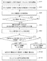
タイマ補正装置1の動作を図2に示すフローチャートを用いて説明する。
The operation of the
第1のクロック発振部10及び第2のクロック発振部11が電源の投入やオペレータ等の操作により起動されて各々の周波数で発振を開始する(S10)。
The first
第1のクロック発振部10及び第2のクロック発振部11の信号は、入力クロック選択部12に出力される。入力クロック選択部12は、いずれか1つの信号を選択し、タイマ発生部17に供給する(S20)。
The signals of the first
クロック測定部13が第1のクロック発振部10からのクロックの測定を開始する(S30)。
The
一方タイマ発生部17は、入力クロック選択部12が選択したクロックを基にカウントを行う。タイマ発生部17は、タイマ発生部17のカウント数が、予め設定したタイマ閾値に達した時、タイマ割込み信号100を出力する(S40)。
On the other hand, the
ここで、本発明の第1の実施の形態のタイマ補正装置1において電源投入後に行われる初期化段階を経て定常作状態になった時点のクロック測定部13によるパルス数の測定値をX0とする。X0はパルス数比率算出部14に備えられた第1の記憶部3に記憶される。また、X0の観測が終了し、第1の記憶部3にX0が記憶された後に、同じくクロック測定部13により測定したパルス数の測定値をXnとする。第2の記憶部4がXnを記憶する。また、Xnは、判断部5およびクロック過不足部15に伝達されて、さらにクロック過不足部15からタイマ閾値補正部16に伝達される。なお引数nは割り込み信号100と次に発生する割り込み信号100との間の状態を一意に区別する為に付与した整数である。例えば、タイマ補正装置が動作中のある時点を状態0と定めた場合、この状態において、クロック測定部13のパルス数の測定値はX0である。同様に、状態0から状態1に当該タイマ補正装置の動作が遷移した場合のクロック測定部13のパルス数の測定値はX1である。したがって、状態が順次遷移して状態nにおける測定値はXnになる。
Here, in the
タイマ発生部17のカウント数が予め設定した閾値に達した時点で、タイマ発生部17が割り込み信号100を出力し、クロック測定部13に伝達する(S50)。
When the count number of the
クロック測定部13が割り込み信号100を受け付けるまでにカウントした数値Xnを読出してパルス数比率算出部14に出力する(S60)。パルス数比率算出部16が受け取ったXnを第2の記憶部4に記憶する。
The
判断部5は、第1の記憶部3からX0と、第2の記憶部4からXnと、を読み出す。判断部5は、X0=Xnであるか否かの判断結果をタイマ閾値補正部16に出力する。判断部5が、X0とXnとの比を算出して、タイマ閾値補正部16に出力する(S70)。
The
X0=Xnである場合(S70=Yes)、タイマ閾値補正部16は、閾値を算出する為の(2)式(後述)に従って、補正タイマ閾値110を算出する(S80)。
When X0 = Xn (S70 = Yes), the timer threshold
X0≠Xnである場合(S70=No)、タイマ閾値補正部16は、閾値を算出する為の(1)式(後述)に従って、補正タイマ閾値110を算出する(S90)。
When X0 ≠ Xn (S70 = No), the timer threshold
補正タイマ閾値110は、タイマ発生部17によって、割り込み信号100を発行する判断に用いられ、前述のタイマ閾値に上書きされる(S100)。
The
クロック過不足累積部15はX0とXnとの数値の差異を算出してクロック過不足累積値(Anと呼ぶ)を一時記憶する。Anの記憶は2世代であり、Anと次の状態であるAn+1を記憶する(S110)。
The clock excess /
その後、フローはS30に戻り、クロック測定部13の動作から、フローが繰り返される。
Thereafter, the flow returns to S30, and the flow is repeated from the operation of the
ここで、タイマ閾値補正部16が行う計算について説明する。
Here, the calculation performed by the timer threshold
まず、タイマ補正装置1が動作し、継続的にタイマ発生部17から割り込み信号110が出力されている場合とする。割り込み信号110が出力された時点から次の割り込み信号110が出力されるまでの期間を状態と表現する。この状態にそれぞれ識別子としてn(整数)を付与し、n番目の状態を状態nと呼ぶ。さらに状態nの期間が終了して、次に動作している状態を状態n+1と呼ぶ。本例の説明における状態の番号は、状態nと次の状態n+1、さらにその次の状態n+2、の様に、状態が連続していることを示す。
First, it is assumed that the
次に、算出に必要なパラメータとその内容を説明する。まず、状態0、すなわち0番目の状態におけるパルス数測定値の基準値となるX0と、状態n、すなわち状態がn番目のパルス数測定値であるXnがある。ここで、状態0から状態Xnに至るまでの、X0と各々のXn(n=1からnまでの全て)との差をそれぞれ加算してその累積値を得る。この累積値がクロック過不足数Anとする。また、閾値を算出する式は2種類あり、X0とXnとが一致するか否かの違いによりいずれか一つの式を選択する。式の詳細は後述する。なお、本説明における、Xn、An、後述するYnの引数nは、状態nにおけるそれぞれの値であることを示す。
Next, parameters required for calculation and their contents will be described. First, there is X0 which is a reference value of the pulse number measurement value in
まず、X0の値とXnとの値が不一致の場合の算出について説明する。この条件は、状態0の割り込み信号100が発生する周期と状態nで割り込み信号100が発生する周期とが異なることを意味する。そこで、まず周期を一致させる為に補正タイマ閾値110の計算を行う。状態nにおける補正タイマ閾値110の値をYnとして、次の状態n+1における補正タイマ閾値110の値をYn+1とすると、Yn+1は下記の(1)式で算出する。
Yn+1=Yn*X0/Xn・・・・(1)
この新たな閾値により、以後のタイマ発生部17のカウント数が補正される。この(1)式は、基準となるカウント数であるX0と状態nにおけるカウント数であるXnとの比を求めて、状態nの時の補正タイマ閾値110の値に前述の比を割かけることで、クロックの周波数が変化したことによるカウント数の増減を基準値となるX0に割かけることで、カウント数が一致することになる。従って、最終的にはX0=Xnに調整される。
First, calculation when the values of X0 and Xn do not match will be described. This condition means that the cycle in which the interrupt
Yn + 1 = Yn * X0 / Xn (1)
The count value of the
また、クロック過不足数の累積値An+1は、下記(3)式で算出する。
An+1=An+X0−Xn・・・・(3)
次に、X0とXnとが一致している場合の算出について説明する。
Further, the cumulative value An + 1 of the number of clock excess / deficiency is calculated by the following equation (3).
An + 1 = An + X0−Xn (3)
Next, calculation when X0 and Xn match will be described.
この条件は、状態0の割り込み信号100が発生する周期と状態nで割り込み信号100が発生する周期とが一致していることを意味している。しかし、周期を一致させる為タイマの閾値を変更した結果、割り込み信号100が出力されるタイミングが、状態0と状態nでは異なっている状態が存在する。それはクロック過不足数Anが0ではない状態である。そこで、状態0の場合に割り込み信号100が出力したタイミングと状態nの割り込み信号100とのタイミングを一致させる為に補正タイマ閾値110の計算を行う。
This condition means that the cycle in which the interrupt
状態nにおける補正タイマ閾値110の値をYnとして、次の状態n+1におけるタイマの時計動作に対する補正タイマ閾値110の値をYn+1とすると、はYn+1は下記(2)式で算出する。
Yn+1=Yn*(X0+An)/Xn・・・・(2)
この(2)式は、X0=Xnに至った後、X0の切り替えタイミングとXnの切り替えタイミングとの差を補正する為にクロック過不足数AnがX0に加算されることでパルス数の補正が行われて、Xnに切替わった後にずれたタイミングの補正を考慮したタイミング補正値を算出する式である。
Assuming that the value of the
Yn + 1 = Yn * (X0 + An) / Xn (2)
In this equation (2), after reaching X0 = Xn, the number of pulses is corrected by adding the clock excess / deficiency number An to X0 in order to correct the difference between the switching timing of X0 and the switching timing of Xn. This is an equation for calculating a timing correction value that takes into account the correction of the timing that has been performed and shifted after switching to Xn.
また、クロック過不足数の累積値An+1は、下記の(4)式で算出する。
An+1=An+X0−Xn・・・・(4)
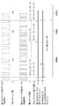
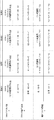
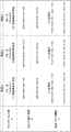
ここでさらに、図1に示したタイマ補正装置1の動作例を、図3A及び図3Bのタイミングチャート図及び図4A及び図4Bのタイマ補正装置1の状態を規定する数値の計算式を示す表を用いてより具体的に説明する。
Further, the cumulative value An + 1 of the number of clock excess / deficiency is calculated by the following equation (4).
An + 1 = An + X0−Xn (4)
Here, the operation example of the
図3A及び図3Bは、第1のクロック発振部10のクロック波形、第2のクロック発振部11のクロック発振波形、補正タイマ閾値110、クロックパルスの過不足数、割り込み信号100が発生するタイミング、本来期待される割り込み信号100のタイミングの小各々の関係を図に表したものである。
3A and 3B show the clock waveform of the first
図4A及び図4Bは、クロック測定部13が測定するクロックパルス数(X0,Xn)とクロック過不足数(An、An+1)を算出する式とその値と、補正タイマ閾値110(Yn、Yn+1)を算出する式とその値と、を図にしたものである。図3A、図3B、に記載した状態0から状態6は図4A及び図4Bの記載した状態0から状態6にそれぞれ対応する。
4A and 4B show the formulas and values for calculating the number of clock pulses (X0, Xn) and the number of clock excess / deficiency (An, An + 1) measured by the
次に、図3A、図3B、図4A及び図4Bを用いて、割り込み信号100の周期の補正及びタイミングを基準のタイミングと一致させる動作について、説明1から説明6の段階にわけて説明する。
Next, with reference to FIG. 3A, FIG. 3B, FIG. 4A and FIG. 4B, the correction of the cycle of the interrupt
ここで、本例の定常状態の定義について説明する。定常状態とは、タイマ補正装置1の電源が投入され、タイマ発生部17及びクロック測定部13に対して初期値を設定して、動作が開始されて、その後、クロック測定部13が測定したパルス数の過渡的な変動が収束して、特定の値を連続して出力する状態に至った状態を言う。
Here, the definition of the steady state of this example will be described. In the steady state, the
(説明1)
定常状態において、タイマ発生部17の入力クロックには、低速の第1のクロック発振部10のクロックが選択されているとする(図3A_状態0、図4A_状態0)。この時、タイマ発生部17が出力する割込み信号100と次に割り込み信号100との間に測定される第1のクロック発振部10からのパルス数をクロック測定部13が測定し、その値をX0とする。この低速の第1のクロック発振部10のクロックによりタイマ発生部17のカウントが実行されて割り込み信号100を出力し、タイマ閾値補正部16が、次回の補正タイマ閾値Ynを計算する(図3A_状態1、図4A_状態1)。定常状態(本例では状態0及び状態0以前の状態が相当する)においては、第1のクロック発振部10のパルスとタイマ発生部17に入力するクロックは同一であり、クロック測定部13が測定する割込み信号100と次に割り込み信号100との間のクロックパルス数は、変化しない。また、定常状態ではクロック過不足は存在せず、クロック過不足数A0は0である。次の状態1における補正タイマ閾値Y1は、X0=Xnの条件を成立することから前述の(2)式を適用する。したがって、前の状態0における補正タイマ閾値Y0に対し、Y1=Y0*(X0+A0)/X0=Y0=5となり、前回の補正タイマ閾値と等しい。つまり、定常状態においては、タイマ割込みは第1のクロックパルス数X0の間隔で発生する。なお、クロック過不足累積部15が、クロック過不足数A1を計算して、A1=A0+X0−X0=0を得る。クロック過不足累積部15がA1を記憶する。
(Explanation 1)
In the steady state, it is assumed that the clock of the low-speed first
(説明2)
状態1の動作を説明する。前述の状態0で計算したタイマ閾値であるY1=5がタイマ発生部17の閾値に設定され、カウントが実行される。
(Description 2)
The operation in
タイマ割込み信号100が発生までの間に、低速の第1のクロック発振部10のクロックから高速の第2のクロック発振部11のクロックに切替わったとする(図3A_状態1、図4A_状態1)。
Before the timer interrupt
高速の第2のクロック発振部11にクロックに切替わったことでタイマ発生部17のカウント速度が上がるが、補正タイマ閾値110が定常状態と等しいY0が適用されたままである為、定常時よりも短い時間で補正タイマ割込み信号100が発生する(図3A_状態1の後端部分、図4A_状態1)。
Although the count speed of the
状態1の期間にクロック測定部13が測定した第1のクロック発振部10のクロックパルス数をX1とする。タイマ発生部17に供給される第2のクロック11のクロックの周波数が第1のクロック10のクロック周波数より高い為、定常時よりも早くタイマ割込みが発生する。X1<X0である。したがって、タイマ発生部17の入力クロックが高速のクロックに切替わった後も、タイマ発生部17の割込み信号100の発生頻度を定常状態と同一に維持する為には、次の状態2におけるタイマ発生部17に対する補正タイマ閾値110は、現在の状態1に適用した補正タイマ閾値であるY1に対して増加させる必要がある。
The number of clock pulses of the first
ここで、X0≠X1の条件(図3Aの状態1を参照するとX0=5、X1=4である。)が成立することから前述の(1)式を適用して次の状態2の補正タイマ閾値Y2を算出する。タイマ閾値補正部16が、Y2=Y1*X0/X1≒6を得る。
Here, since the condition of X0 ≠ X1 (X0 = 5 and X1 = 4 when referring to
また、タイマ割込み信号100が発生する間に本来測定すべき第1のクロック発振部10のクロックパルス数はX0だが、実際に測定されたクロックパルス数はX1である為、タイマ割込みが発生したタイミングは、定常時と比べてX0−X1分のずれが生じている。さらに、X0≠X1の条件となることから、クロック過不足累積部15が前述の(3)式を適用してクロック過不足数A2を計算して、A2=A1+X0−X1=1を得る。クロック過不足累積部15がA2を記憶する。
In addition, the number of clock pulses of the first
(説明3)
次に、状態2を説明する。入力クロックは高速の第2のクロックが供給されたままであったとする(図3A_状態2〜状態3、図4A_状態2〜状態3)。補正タイマ閾値Y2を基に、割り込み信号100が発生するが、前回はタイマ発生部17の入力クロックが途中から第2のクロック発振部11のクロックに切替わったのに対し、今回は初めから第2のクロック発振部11のクロックで動作している為、前回よりも短い間隔でタイマ割込みが発生する(図3A_状態2の後端の部分、図4A_状態2)。この時に、状態2の期間でクロック測定部13が測定したクロックパルス数をX2とする。前回よりも早く割り込み信号100が発生した為、X2<X1<X0である。X0≠X2の条件である。よって、タイマ閾値補正部16が、前述の(1)式を適用して、次の状態3の補正タイマ閾値Y3を計算して,Y3=Y2*X0/X2=10を得る。これにより、タイマ発生部17に入力するクロックが、第2のクロック11が出力するクロックのままであれば、次の状態3の期間で測定される第1のクロック発振部10からのクロックパルス数は、定常時と同じ値になる。なお、X0≠X2の条件が成立することから、クロック過不足部累積部15が前述の(3)式を適用して、クロック過不足数A3を計算して、A3=A2+X0−X2=3を得る。クロック過不足累積部15がA3を記憶する。
(Explanation 3)
Next, state 2 will be described. Assume that the high-speed second clock is still supplied as the input clock (FIG. 3A_state 2 to
(説明4)
次の状態3も、入力クロックは高速の第2のクロック11からの供給のままであったとする(図3A_状態3、図4A_状態3)。状態3で算出した補正タイマ閾値Y3はY2より大きく、かつ入力クロックに変化がないため、前回よりも長い間隔でタイマ割込みが発生し、定常時と間隔は等しくなる(図3B_状態3の後端の部分、図4B_状態3)。この時にクロック測定部13が測定した、第1のクロック発振部10のクロックパルス数をX3とする。定常時と割り込み信号100が発生する間隔が等しい為、X3=X0である。X3=X0の条件が成立することから、補正タイマ閾値Y4の計算には前述の(2)式を適用する。タイマ閾値補正部16が、次の状態4の補正タイマ閾値Y4を計算して、Y4=Y3*(X0+A3)/X3=16を得る。なお、X3=X0であるため、Y4=Y3*(X0+A3)/X0とも言える。また、X3=X0の条件が成立することから、クロック過不足数A4の計算には前述の(4)式を適用する。クロック過不足累積部15が、クロック過不足数A4を計算して、A4=A3+X0−X3=3を得る。クロック過不足累積部15がA4を記憶する(この場合の過不足数は変化しない)。
(Explanation 4)
In the
(説明5)
次の状態4も、タイマ発生部17に入力するクロックが、高速の第2のクロック11が出力するクロックのままであったとする(図3B_状態4、図4B_状態4)。補正タイマ閾値Y4はY3より大きく、かつ入力クロックに変化がないため、前回よりも長い間隔でタイマ割込みが発生する(図3B_状態4の後端の部分、図4B_状態4)。この時にクロック測定部13が測定した、第1のクロック発振部10のクロックパルス数をX4とする。入力クロックの周波数は前回から変化がなく、また、前回補正された補正タイマ閾値は、クロック過不足数の分のみ増えている為、X4=X3+A3である。X4≠X0の条件が成立することから補正タイマ閾値Y5の計算には前述の(1)式を適用する。タイマ閾値補正部16が、次の状態5の補正タイマ閾値Y5を計算して、Y5=Y4*X0/X4=10を得る。なお、(説明4)で述べたようにY4=Y3*(X0+A3)/X3、X3=X0である為、次回の補正タイマ閾値Y5は前々回の補正タイマ閾値Y3と等しくなる。前々回の補正タイマ閾値Y3は、入力クロックが第2のクロック発振部11のクロックの時、定常時のタイマ割込み発生間隔と等しくなる値である。また、X4≠X0の条件が成立することから、クロック過不足数A5の計算には前述の(3)式を適用する。クロック過不足累積部15が、クロック過不足数A5を計算して、A5=A4+X0−X4=0を得る。クロック過不足累積部15がA5を記憶する。
(Explanation 5)
In the next state 4 as well, it is assumed that the clock input to the
(説明6)
次の状態5の期間も、入力クロックは高速の第2のクロックのままであったとする(図3B_状態5、図4B_状態5)。前回補正された補正タイマ閾値Y5はY4より小さく、かつ入力クロックに変化がないため、前回よりも短い間隔でタイマ割込みが発生する(図3B_状態5の最後の部分、図4B_状態5)。この時に測定された、クロック測定部13が測定した、第1のクロック発振部10のクロックパルス数をX5とする。入力クロック周波数に変化がなく、また、補正タイマ閾値Y5は前々回の補正タイマ閾値Y3と等しい値であった為、X5=X3=X0となる。X5=X0の条件が成立することから補正タイマ閾値Y6の計算には前述の(2)式を適用する。タイマ閾値補正部16が、次の状態6の補正タイマ閾値Y6を、Y6=Y5*(X0+A5)/X5の式で計算するが、X5=X0、Y5=Y3、A5=0であるため、補正タイマ閾値Y6は補正タイマ閾値Y3と等しく10になる。よって、入力クロック周波数が変更されない限り、タイマ割込み発生間隔は、定常状態のタイマ割込み発生間隔と等しくなる。また、X5=X0の条件が成立することから、クロック過不足数A6の計算には前述の(4)式を適用する。クロック過不足累積部15が、クロック過不足数A6を計算して、A6=A5+X0−X5=0を得る。クロック過不足累積部1がA6を記憶する。
(Explanation 6)
It is assumed that the input clock remains the second high-speed clock during the next state 5 (FIG. 3B_state 5 and FIG. 4B_state 5). Since the correction timer threshold Y5 corrected last time is smaller than Y4 and the input clock does not change, a timer interrupt is generated at an interval shorter than the previous time (the last part of FIG.
以上により、入力クロックを切り替えた後の割り込み信号100が発生する間隔が入力クロック切り替え前と等しく、かつ入力クロック切り替えた後のタイマ割込み発生タイミングも、入力クロック切り替え前と一致する。なお、入力クロックを高速クロックから低速クロックに変更する場合も同様である。
As described above, the interval at which the interrupt
以上の様に、本発明の第1の実施の形態におけるタイマ補正装置1は、周波数の異なるクロックに切り替えても、切り替える前の割り込み信号の周期と位相とを一致させることが出来る。その理由は、周期を合わせる補正に加えて位相を合わせる補正を行うことが出来るからである。
As described above, the
1 タイマ補正装置
3 第1の記憶部
4 第2の記憶部
5 判断部
10 第1のクロック発振部
11 第2のクロック発振部
12 入力クロック選択部
13 クロック測定部
14 パルス数比率算出部
15 クロック過不足累積部
16 タイマ閾値補正部
17 タイマ発生部
100 割り込み信号
110 補正タイマ閾値
DESCRIPTION OF
Claims (9)
前記第1のクロック発振手段とは異なる周波数を出力する第2のクロック発振手段と、
第1のクロックと第2のクロックのいずれか一つを選択して、選択したクロックをタイマ発生部に出力する入力クロック選択部と、
基準クロックでカウントするパルス数を測定する入力クロック測定部と、
前記クロック測定部がカウントする各周期のパルス数を比較して、前記パルス数の過不足の累積を行うクロック過不足累積部と、
前記入力クロック測定部が測定したパルス数の比と差を算出するパルス数比率算出部と、
前記パルス数の比と前記差とからカウンタが割り込み信号を出力する条件の閾値を与えるタイマ閾値補正部と、
前記入力クロック選択部からのクロックでカウントし、前記閾値による前記割り込み信号を出力するタイマ発生部と、
を備え、
前記入力クロック測定部は、第1のクロックを受け取り、前記タイマ発生部が出力した第1の割り込み信号と次の周期である第2の記割り込み信号との間に受け取った前記第1のクロックのパルス数を計側して第1の測定値とし、前記第1の測定値を測定した後の測定値を第2の測定値として、前記第1の測定値と前記第2の測定値とをパルス数比率算出部に出力し、
前記クロック過不足累積部は、前記第1の測定値と前記第2の測定値との差に前の周期で得られた第1の累積値とを加算して第2の累積値を求め、次の周期の加算で、前記第1の累積値に前記第2の累積値を代入して再帰的に算出した前記第2の累積値をクロック過不足数として前記タイマ閾値補正部に出力し、
前記パルス数比率算出部は、前記第1の測定値を記憶する第1の記憶部と、
前記第2の測定値を記憶する第2の記憶部と、
前記第1の測定値と前記第2の測定値が一致するか否かの判断情報と、前記第1の測定値と前記第2の測定値との比と、をタイマ閾値補正部に出力する判断部と、
を含み、
前記タイマ閾値補正部は、前記パルス数比率算出部の前記判断部から、前記判断情報と前記比の情報を受け取り、タイマ発生部のカウンタの前記閾値を算出して当該閾値を記憶し、当該閾値をタイマ発生部に出力し、
前記タイマ発生部は、前記入力クロック選択部が出力するクロックでカウントを行い、カウント値を前記タイマ閾値補正部が出力した閾値に設定して当該カウンタをカウントダウンさせて、カウンタが0になった時に、前記タイマ発生部から、前記第1の割り込み信号及び前記第2の割り込み信号と、を前記クロック測定部及び外部装置に出力する、
タイマ補正装置。 First clock oscillation means for outputting a clock having a reference frequency;
Second clock oscillation means for outputting a frequency different from that of the first clock oscillation means;
An input clock selection unit that selects one of the first clock and the second clock and outputs the selected clock to the timer generation unit;
An input clock measurement unit that measures the number of pulses counted by the reference clock;
Compare the number of pulses in each cycle counted by the clock measurement unit, and accumulate the excess / deficiency of the number of pulses, and a clock excess / deficiency accumulation unit,
A pulse number ratio calculation unit for calculating a ratio and difference between the pulse numbers measured by the input clock measurement unit;
A timer threshold value correction unit that gives a threshold value for the condition that the counter outputs an interrupt signal from the ratio of the number of pulses and the difference;
A timer generation unit that counts with the clock from the input clock selection unit and outputs the interrupt signal according to the threshold;
With
The input clock measuring unit receives a first clock, and receives the first clock received between the first interrupt signal output from the timer generating unit and the second interrupt signal of the next cycle. The first measured value and the second measured value are obtained by measuring the number of pulses as the first measured value, and the measured value after measuring the first measured value as the second measured value. Output to the pulse number ratio calculator,
The clock excess / deficiency accumulating unit obtains a second accumulated value by adding the first accumulated value obtained in the previous cycle to the difference between the first measured value and the second measured value, In the addition of the next period, the second cumulative value that is recursively calculated by substituting the second cumulative value into the first cumulative value is output to the timer threshold value correction unit as a clock excess / deficiency number,
The pulse number ratio calculation unit includes a first storage unit that stores the first measurement value;
A second storage unit for storing the second measurement value;
The determination information as to whether or not the first measurement value and the second measurement value match, and the ratio between the first measurement value and the second measurement value are output to a timer threshold value correction unit. A determination unit;
Including
The timer threshold value correction unit receives the determination information and the ratio information from the determination unit of the pulse number ratio calculation unit, calculates the threshold value of the counter of the timer generation unit, stores the threshold value, and stores the threshold value. Is output to the timer generator,
The timer generation unit counts with the clock output from the input clock selection unit, sets the count value to the threshold value output by the timer threshold value correction unit, counts down the counter, and when the counter reaches 0 The timer generation unit outputs the first interrupt signal and the second interrupt signal to the clock measurement unit and an external device.
Timer correction device.
前記第1のクロックとは異なる周波数の第2のクロックを発振させ、
第1のクロックを受け取り、第1の割り込み信号と次の周期である第2の記割り込み信号との間に受け取った前記第1のクロックのパルス数を測定して第1の測定値とし、前記第1の測定値を測定した後の測定値を第2の測定値として、前記第1の測定値と前記第2の測定値とをパルス数比率算出部に出力し、
前記第1の測定値と前記第2の測定値との差に前の周期で得られた第1の累積値とを加算して第2の累積値を求め、次の周期の加算で、前記第1の累積値に前記第2の累積値を代入して再帰的に算出した前記第2の累積値を出力し、
前記第1の測定値と前記第2の測定値が一致するか否かの判断情報と、前記第1の測定値と前記第2の測定値との比を出力し、
前記判断情報と前記比の情報を受け取り、カウンタの前記閾値を算出して当該閾値を記憶し、当該閾値を出力し、
前記入力クロック選択部が出力するクロックでカウントを行い、カウント値を閾値に設定して当該カウンタをカウントダウンさせて、カウンタが0になった時に、前記タイマ発生部から、前記第1の割り込み信号及び前記第2の割り込み信号と、を前記クロック測定部及び外部装置に出力する、タイマ補正方法。 Oscillate the first clock that is the reference frequency,
Oscillating a second clock having a different frequency from the first clock;
Receiving the first clock, measuring the number of pulses of the first clock received between the first interrupt signal and the second interrupt signal of the next period as a first measurement value, The measurement value after measuring the first measurement value is set as the second measurement value, and the first measurement value and the second measurement value are output to the pulse number ratio calculation unit,
The difference between the first measured value and the second measured value is added to the first accumulated value obtained in the previous period to obtain a second accumulated value, and in the addition of the next period, Outputting the second cumulative value recursively calculated by substituting the second cumulative value for the first cumulative value;
A determination information as to whether or not the first measurement value and the second measurement value match, and a ratio between the first measurement value and the second measurement value;
Receiving the judgment information and the ratio information, calculating the threshold value of the counter, storing the threshold value, and outputting the threshold value;
Counting with the clock output from the input clock selection unit, setting the count value as a threshold and counting down the counter, and when the counter reaches 0, the timer generation unit outputs the first interrupt signal and A timer correction method for outputting the second interrupt signal to the clock measurement unit and an external device.
前記第1のクロックとは異なる周波数の第2のクロックを発振させ、
第1のクロックを受け取り、第1の割り込み信号と次の周期である第2の記割り込み信号との間に受け取った前記第1のクロックのパルス数を測定して第1の測定値とし、前記第1の測定値を測定した後の測定値を第2の測定値として、前記第1の測定値と前記第2の測定値とをパルス数比率算出部に出力し、
前記第1の測定値と前記第2の測定値との差に前の周期で得られた第1の累積値とを加算して第2の累積値を求め、次の周期の加算で、前記第1の累積値に前記第2の累積値を代入して再帰的に算出した前記第2の累積値を出力し、
前記第1の測定値と前記第2の測定値が一致するか否かの判断情報と、前記第1の測定値と前記第2の測定値との比を出力し、
前記判断情報と前記比の情報を受け取り、カウンタの前記閾値を算出して当該閾値を記憶し、当該閾値を出力し、
前記入力クロック選択部が出力するクロックでカウントを行い、カウント値を閾値に設定して当該カウンタをカウントダウンさせて、カウンタが0になった時に、前記タイマ発生部から、前記第1の割り込み信号及び前記第2の割り込み信号と、を前記クロック測定部及び外部装置に出力する処理をコンピュータに実行させるタイマ補正プログラム。 Oscillate the first clock that is the reference frequency,
Oscillating a second clock having a different frequency from the first clock;
Receiving the first clock, measuring the number of pulses of the first clock received between the first interrupt signal and the second interrupt signal of the next period as a first measurement value, The measurement value after measuring the first measurement value is set as the second measurement value, and the first measurement value and the second measurement value are output to the pulse number ratio calculation unit,
The difference between the first measured value and the second measured value is added to the first accumulated value obtained in the previous period to obtain a second accumulated value, and in the addition of the next period, Outputting the second cumulative value recursively calculated by substituting the second cumulative value for the first cumulative value;
A determination information as to whether or not the first measurement value and the second measurement value match, and a ratio between the first measurement value and the second measurement value;
Receiving the judgment information and the ratio information, calculating the threshold value of the counter, storing the threshold value, and outputting the threshold value;
Counting with the clock output from the input clock selection unit, setting the count value as a threshold and counting down the counter, and when the counter reaches 0, the timer generation unit outputs the first interrupt signal and The timer correction program which makes a computer perform the process which outputs a said 2nd interruption signal to the said clock measurement part and an external device.
Priority Applications (1)
| Application Number | Priority Date | Filing Date | Title |
|---|---|---|---|
| JP2015065386A JP6500550B2 (en) | 2015-03-27 | 2015-03-27 | Timer correction device, timer correction method and timer correction program |
Applications Claiming Priority (1)
| Application Number | Priority Date | Filing Date | Title |
|---|---|---|---|
| JP2015065386A JP6500550B2 (en) | 2015-03-27 | 2015-03-27 | Timer correction device, timer correction method and timer correction program |
Publications (2)
| Publication Number | Publication Date |
|---|---|
| JP2016184366A true JP2016184366A (en) | 2016-10-20 |
| JP6500550B2 JP6500550B2 (en) | 2019-04-17 |
Family
ID=57243046
Family Applications (1)
| Application Number | Title | Priority Date | Filing Date |
|---|---|---|---|
| JP2015065386A Active JP6500550B2 (en) | 2015-03-27 | 2015-03-27 | Timer correction device, timer correction method and timer correction program |
Country Status (1)
| Country | Link |
|---|---|
| JP (1) | JP6500550B2 (en) |
Cited By (1)
| Publication number | Priority date | Publication date | Assignee | Title |
|---|---|---|---|---|
| CN114269306A (en) * | 2019-09-02 | 2022-04-01 | 花王株式会社 | Method and apparatus for manufacturing workpiece, and method and apparatus for manufacturing fused-sheet body |
Citations (5)
| Publication number | Priority date | Publication date | Assignee | Title |
|---|---|---|---|---|
| JPH08292822A (en) * | 1995-04-20 | 1996-11-05 | Nec Eng Ltd | Intelligent timer |
| JPH1020052A (en) * | 1996-07-01 | 1998-01-23 | Yazaki Corp | Time correction method and device therefor |
| JP2006309479A (en) * | 2005-04-28 | 2006-11-09 | Nec Electronics Corp | Clock correction circuit, clock correction method, and microcontroller |
| JP2013183403A (en) * | 2012-03-05 | 2013-09-12 | Nec Corp | Clock phase synchronization device and clock phase synchronization method |
| JP2014010704A (en) * | 2012-06-29 | 2014-01-20 | Renesas Electronics Corp | Clock correction circuit and clock correction method |
-
2015
- 2015-03-27 JP JP2015065386A patent/JP6500550B2/en active Active
Patent Citations (5)
| Publication number | Priority date | Publication date | Assignee | Title |
|---|---|---|---|---|
| JPH08292822A (en) * | 1995-04-20 | 1996-11-05 | Nec Eng Ltd | Intelligent timer |
| JPH1020052A (en) * | 1996-07-01 | 1998-01-23 | Yazaki Corp | Time correction method and device therefor |
| JP2006309479A (en) * | 2005-04-28 | 2006-11-09 | Nec Electronics Corp | Clock correction circuit, clock correction method, and microcontroller |
| JP2013183403A (en) * | 2012-03-05 | 2013-09-12 | Nec Corp | Clock phase synchronization device and clock phase synchronization method |
| JP2014010704A (en) * | 2012-06-29 | 2014-01-20 | Renesas Electronics Corp | Clock correction circuit and clock correction method |
Cited By (2)
| Publication number | Priority date | Publication date | Assignee | Title |
|---|---|---|---|---|
| CN114269306A (en) * | 2019-09-02 | 2022-04-01 | 花王株式会社 | Method and apparatus for manufacturing workpiece, and method and apparatus for manufacturing fused-sheet body |
| CN114269306B (en) * | 2019-09-02 | 2022-11-22 | 花王株式会社 | Method and apparatus for manufacturing workpiece, and method and apparatus for manufacturing fused-sheet body |
Also Published As
| Publication number | Publication date |
|---|---|
| JP6500550B2 (en) | 2019-04-17 |
Similar Documents
| Publication | Publication Date | Title |
|---|---|---|
| JP5886015B2 (en) | Time measuring device, microcontroller, program, and time measuring method | |
| EP2369438B1 (en) | Calibration method of a real time clock signal | |
| CN109067394B (en) | On-chip clock calibration device and calibration method | |
| JP2007094931A (en) | Correction clock generation circuit and usb device equipped with the same | |
| JP6268020B2 (en) | Clock generation method and semiconductor device | |
| KR20070016434A (en) | Real time clock apparatus and the real time compensating method thereof | |
| EP0590607B1 (en) | Low-power baud rate generator | |
| JP2008028854A (en) | Clock generator | |
| JP6990313B2 (en) | Semiconductor integrated circuit | |
| CN110289851A (en) | A kind of output method of synchronization pulse, device, equipment and computer media | |
| JP6500550B2 (en) | Timer correction device, timer correction method and timer correction program | |
| JP4487937B2 (en) | Microcomputer | |
| JP2001013179A (en) | Measurement method for ring oscillator clock frequency, measurement circuit for ring oscillator clock frequency, and microcomputer | |
| JP5914718B2 (en) | Time base with oscillator, frequency division circuit and clock pulse suppression circuit | |
| TW201813303A (en) | Mitigation of long wake-up delay of a crystal oscillator | |
| JP2011053057A (en) | Time correction circuit and electronic device | |
| JP6274638B2 (en) | Frequency adjustment circuit and frequency adjustment method | |
| JP2022006391A (en) | Frequency measuring device, microcontroller and electronic device | |
| JP2015015540A5 (en) | ||
| JP2021182808A (en) | Synchronous control system | |
| JP5294718B2 (en) | Frequency converter | |
| JP4036114B2 (en) | Clock generation circuit | |
| JP7173833B2 (en) | Semiconductor integrated circuits and devices equipped with the semiconductor integrated circuits | |
| JP5037285B2 (en) | Pulse signal time measuring device | |
| JP2016086385A (en) | PWM signal output circuit |
Legal Events
| Date | Code | Title | Description |
|---|---|---|---|
| A621 | Written request for application examination |
Free format text: JAPANESE INTERMEDIATE CODE: A621 Effective date: 20180215 |
|
| A977 | Report on retrieval |
Free format text: JAPANESE INTERMEDIATE CODE: A971007 Effective date: 20180831 |
|
| A131 | Notification of reasons for refusal |
Free format text: JAPANESE INTERMEDIATE CODE: A131 Effective date: 20180918 |
|
| A521 | Request for written amendment filed |
Free format text: JAPANESE INTERMEDIATE CODE: A523 Effective date: 20181102 |
|
| TRDD | Decision of grant or rejection written | ||
| A01 | Written decision to grant a patent or to grant a registration (utility model) |
Free format text: JAPANESE INTERMEDIATE CODE: A01 Effective date: 20190219 |
|
| A61 | First payment of annual fees (during grant procedure) |
Free format text: JAPANESE INTERMEDIATE CODE: A61 Effective date: 20190304 |
|
| R150 | Certificate of patent or registration of utility model |
Ref document number: 6500550 Country of ref document: JP Free format text: JAPANESE INTERMEDIATE CODE: R150 |