JP2016149366A - System level power delivery to plasma processing load - Google Patents
System level power delivery to plasma processing load Download PDFInfo
- Publication number
- JP2016149366A JP2016149366A JP2016053392A JP2016053392A JP2016149366A JP 2016149366 A JP2016149366 A JP 2016149366A JP 2016053392 A JP2016053392 A JP 2016053392A JP 2016053392 A JP2016053392 A JP 2016053392A JP 2016149366 A JP2016149366 A JP 2016149366A
- Authority
- JP
- Japan
- Prior art keywords
- generator
- power
- matching network
- sensor
- local controller
- Prior art date
- Legal status (The legal status is an assumption and is not a legal conclusion. Google has not performed a legal analysis and makes no representation as to the accuracy of the status listed.)
- Granted
Links
Images


Classifications
-
- H—ELECTRICITY
- H01—ELECTRIC ELEMENTS
- H01J—ELECTRIC DISCHARGE TUBES OR DISCHARGE LAMPS
- H01J37/00—Discharge tubes with provision for introducing objects or material to be exposed to the discharge, e.g. for the purpose of examination or processing thereof
- H01J37/32—Gas-filled discharge tubes
- H01J37/32009—Arrangements for generation of plasma specially adapted for examination or treatment of objects, e.g. plasma sources
- H01J37/32082—Radio frequency generated discharge
- H01J37/32174—Circuits specially adapted for controlling the RF discharge
- H01J37/32183—Matching circuits
-
- H—ELECTRICITY
- H05—ELECTRIC TECHNIQUES NOT OTHERWISE PROVIDED FOR
- H05H—PLASMA TECHNIQUE; PRODUCTION OF ACCELERATED ELECTRICALLY-CHARGED PARTICLES OR OF NEUTRONS; PRODUCTION OR ACCELERATION OF NEUTRAL MOLECULAR OR ATOMIC BEAMS
- H05H1/00—Generating plasma; Handling plasma
- H05H1/24—Generating plasma
- H05H1/26—Plasma torches
- H05H1/32—Plasma torches using an arc
- H05H1/34—Details, e.g. electrodes, nozzles
- H05H1/40—Details, e.g. electrodes, nozzles using applied magnetic fields, e.g. for focusing or rotating the arc
-
- H—ELECTRICITY
- H01—ELECTRIC ELEMENTS
- H01L—SEMICONDUCTOR DEVICES NOT COVERED BY CLASS H10
- H01L21/00—Processes or apparatus adapted for the manufacture or treatment of semiconductor or solid state devices or of parts thereof
- H01L21/02—Manufacture or treatment of semiconductor devices or of parts thereof
- H01L21/04—Manufacture or treatment of semiconductor devices or of parts thereof the devices having at least one potential-jump barrier or surface barrier, e.g. PN junction, depletion layer or carrier concentration layer
- H01L21/18—Manufacture or treatment of semiconductor devices or of parts thereof the devices having at least one potential-jump barrier or surface barrier, e.g. PN junction, depletion layer or carrier concentration layer the devices having semiconductor bodies comprising elements of Group IV of the Periodic System or AIIIBV compounds with or without impurities, e.g. doping materials
- H01L21/30—Treatment of semiconductor bodies using processes or apparatus not provided for in groups H01L21/20 - H01L21/26
- H01L21/302—Treatment of semiconductor bodies using processes or apparatus not provided for in groups H01L21/20 - H01L21/26 to change their surface-physical characteristics or shape, e.g. etching, polishing, cutting
- H01L21/306—Chemical or electrical treatment, e.g. electrolytic etching
- H01L21/3065—Plasma etching; Reactive-ion etching
-
- H—ELECTRICITY
- H03—ELECTRONIC CIRCUITRY
- H03H—IMPEDANCE NETWORKS, e.g. RESONANT CIRCUITS; RESONATORS
- H03H7/00—Multiple-port networks comprising only passive electrical elements as network components
- H03H7/38—Impedance-matching networks
- H03H7/40—Automatic matching of load impedance to source impedance
-
- H—ELECTRICITY
- H05—ELECTRIC TECHNIQUES NOT OTHERWISE PROVIDED FOR
- H05H—PLASMA TECHNIQUE; PRODUCTION OF ACCELERATED ELECTRICALLY-CHARGED PARTICLES OR OF NEUTRONS; PRODUCTION OR ACCELERATION OF NEUTRAL MOLECULAR OR ATOMIC BEAMS
- H05H2242/00—Auxiliary systems
- H05H2242/20—Power circuits
- H05H2242/26—Matching networks
Abstract
Description
(関連出願の引用)
本願は、米国仮特許出願第61/429,472号(2011年1月4日出願)の利益を主張する。該出願第61/429,472号の詳細は、その全体が、あらゆる適切な目的のために参照により本明細書に引用される。
(Citation of related application)
This application claims the benefit of US Provisional Patent Application No. 61 / 429,472 (filed Jan. 4, 2011). The details of said application 61 / 429,472 are hereby incorporated by reference in their entirety for any suitable purpose.
(発明の分野)
本発明は、プラズマ処理負荷に対する一貫した電力送達の維持に関する。より具体的には、発電機、整合ネットワーク、センサのシステムレベル統合と、それらの監視および制御に関する。
(Field of Invention)
The present invention relates to maintaining consistent power delivery to plasma processing loads. More specifically, it relates to system level integration of generators, matching networks, sensors and their monitoring and control.
半導体製造において、特徴を小型化することに対する継続的な努力は、ツール製造業者およびプロセス開発者等にとって、有意な課題を呈する。新しい材料の導入と組み合わせられた、より高い均一性、重要寸法のより厳しい制御、プラズマ損傷の低減、より薄い層、およびより短いプロセス時間等の要件は、半導体処理ツールの開発において、より高い精巧さを要求する。これらの要件は、プラズマチャンバに該当し、かつ電力送達システムにも及ぶ。 In semiconductor manufacturing, continued efforts to miniaturize features present significant challenges for tool manufacturers and process developers. Requirements such as higher uniformity, tighter control of critical dimensions, reduced plasma damage, thinner layers, and shorter process times, combined with the introduction of new materials, are becoming more sophisticated in the development of semiconductor processing tools. Request These requirements apply to the plasma chamber and extend to the power delivery system.
人間オペレータは、典型的には、発電機および整合ネットワークからの複数のセンサ出力を監視し、不完全かつ比較的にゆっくりである試みにおいて、多数のパラメータを調節し、プラズマ負荷に対して一貫した電力送達を維持する。オペレータは、システムの種々の構成要素から情報を収集し、オペレータのために、この情報を表示し、オペレータからのコマンドをシステムの種々の構成要素に伝送する外部コントローラと相互作用し得る。この構成は、過去には機能していたが、電流システムに適切ではない場合があることが徐々に明白となっている。 Human operators typically monitor multiple sensor outputs from generators and matching networks and adjust numerous parameters in an attempt to be incomplete and relatively slow and consistent with plasma loading Maintain power delivery. The operator can interact with an external controller that collects information from the various components of the system, displays this information for the operator, and transmits commands from the operator to the various components of the system. Although this configuration has worked in the past, it has become increasingly clear that it may not be appropriate for current systems.
例として、エッチングプロセスにおける主要な進歩は、パルス発信および多重発電機同期パルス発信の間の発電機周波数同調を含む、高度な能力を伴う、最新世代型RF電源の導入によってもたらされた。しかし、この最先端の電力送達システムでさえ、システム構成要素は、独立して作用し、したがって、独立して、制御されるため、依然として、抑制されている。特に、発電機は、パルス状電力に同調可能周波数を提供するが、整合ネットワークは、パルス状信号を検出し、測定し、それに応答することが困難であって、したがって、発電機の能力を利用することが困難である。オペレータは、整合ネットワーク内の最適可変キャパシタ位置を選択し、次いで、プロセスを起動する傾向がある(すなわち、リアルタイム電力反射を最小限にするための準最適解決策)。したがって、有意な改良が、プラズマ処理電源に行われたが、これらは、発電機および整合ネットワークの独立制御によって、抑制され続ける。 As an example, a major advance in the etching process has been brought about by the introduction of the latest generation RF power source with advanced capabilities, including generator frequency tuning between pulsed and multi-generator synchronized pulsed. However, even with this state-of-the-art power delivery system, system components still remain constrained because they act independently and are therefore independently controlled. In particular, the generator provides a tunable frequency to the pulsed power, but the matching network is difficult to detect, measure and respond to the pulsed signal, and therefore takes advantage of the generator's capabilities Difficult to do. The operator tends to select the optimal variable capacitor location in the matching network and then start the process (ie, a sub-optimal solution to minimize real-time power reflection). Thus, significant improvements have been made to the plasma processing power supply, which continue to be suppressed by independent control of the generator and matching network.
図1は、当業者に周知の発電機、整合ネットワーク、およびプラズマ負荷を図示する。発電機102は、整合ネットワーク104を介して、電力をプラズマ負荷106に提供し、その場合、整合ネットワーク104は、負荷106のインピーダンスが変化するにつれて、発電機102によって経験されるインピーダンスが、実質的に、一定(例えば、50Ω)のままであるように、内部インピーダンスを変更し得る。整合ネットワーク104は、典型的には、整合ネットワーク104に入射する電力および整合ネットワーク104から発電機102に反射される電力を測定し、次いで、これらの値を使用して、プラズマ負荷106のインピーダンスを計算する、センサ116を含む。発電機102は、多くの場合、発電機102の電力出力を測定する、センサ114を含む。センサ114、116は、時として、外部ユーザインターフェース130を介して、その測定値をユーザに通信する。ユーザは、次いで、整合ネットワーク104および/または発電機102に、システムを同調させる試みにおいて、順応するように命令する。
FIG. 1 illustrates a generator, matching network, and plasma load well known to those skilled in the art. The
特に、発電機102は、特定の電気特性(例えば、電力または周波数)を産生するように命令されることができるか、またはプラズマ負荷106に送達される所望の電力が、選択されることができ、発電機102は、その電力を達成するように同調することができる。同様に、整合ネットワーク104は、特定のインピーダンスで動作するように命令されることができるか、または所望の反射された電力を達成するために、同調するように命令されることができる。ある場合には、発電機102および整合ネットワーク104は両方とも、所望の電力出力特性を満たすために、同調するように命令されることができる。
In particular, the
発電機102は、時として、センサ114、無線周波数(RF)エンジン113、およびユーザインターフェース130間の通信を促進する、通信および論理ボード112を含む。RFエンジン113は、RF電力を生成し、発電機102によって生成される電力の振幅および波形を制御することができる。同様に、整合ネットワーク104は、時として、センサ116、インピーダンス制御システム115、およびユーザインターフェース130間の通信を促進する、通信および論理ボード122を含む。インピーダンス制御システム115は、例えば、モータ駆動ボードに整合ネットワーク104の可変キャパシタを調節させることによって、整合ネットワーク104のインピーダンスを制御することができる。
The
この電力送達システム100は、プラズマ負荷106および発電機102からの動的電力プロファイル(電力精度または一貫性)の変化にゆっくりと適応することができる。例えば、センサ114、116のいずれかによる測定の瞬間と、測定された値がユーザインターフェース130に到達する瞬間との間には、遅延が存在する。また、命令が、発電機102および整合ネットワーク104に返信されるときにも、遅延が存在する。
The
精度に関して、整合ネットワーク104のセンサ116は、閾値電流または電圧が検出された後のみ、サンプリングを行い、したがって、電力が閾値と比較されている間、サンプリングを行わない。より小さいサンプルサイズおよびパルス発信の開始からのサンプリング不能は、あまり正確ではないインピーダンス測定につながる。また、各センサ114、116を較正するにもかかわらず、センサ114、116は、依然として、あるレベルの誤差を有し、したがって、組み合わせて使用されるとき、正味の影響として、個々のセンサ114、116の誤差の和にほぼ相当する誤差を有する。最後に、インピーダンス測定は、測定されている電力の周波数が既知であるときに最も正確に行われる。整合ネットワーク106のセンサ116は、整合ネットワーク104に到達する電力の周波数を測定する必要があり、この測定値は、典型的には、ある程度の誤差を有するため、センサ116の測定値に基づいて計算されたインピーダンスもまた、典型的には、ある対応する程度の誤差を有する。明らかなように、速度および精度は、図1のものに類似する従来のシステムでは、制限される。
For accuracy, the
電力送達システム100の不正確さおよび低速は、非一貫性の電力送達につながる可能性があるため、品質もまた、当技術分野において妨害され得る。ある場合には、複数の発電機が、複数の整合ネットワークを介して、単一プラズマ負荷に電力を送給する。各発電機および整合ネットワークは、プラズマ負荷のみならず、相互に可視である他の発電機も考慮する必要があるため、電力品質は、これらの場合において、特に問題である。言い換えると、インピーダンス整合の課題は、複数の発電機が関与する場合、増加し、したがって、電力品質は、複数の発電機が使用されるとき、さらに劣化される。
Quality can also be hindered in the art because inaccuracies and slow speeds of the
図1のシステムは、過去には、適切であり得たが、精度、安定性、および短処理ステップのより厳格な要件を伴う新しいプロセスの非線形動的プラズマ負荷特性に対する、迅速に順応する正確な一貫した電力を提供するために適切ではない場合がある。 The system of FIG. 1 may have been suitable in the past, but it is accurate to quickly adapt to the nonlinear dynamic plasma loading characteristics of the new process with more stringent requirements for accuracy, stability, and short processing steps. It may not be appropriate to provide consistent power.
本開示は、1つ以上のセンサを介して、発電機、整合ネットワーク、およびプラズマ負荷の特性を監視し、プラズマ負荷に対する電力送達精度および一貫性を改善するために、ローカルコントローラを介して、これらの構成要素を制御するように構成される電力送達システムおよび動作方法について論じる。 The present disclosure monitors the characteristics of the generator, matching network, and plasma load via one or more sensors, and improves the power delivery accuracy and consistency for the plasma load through these local controllers. A power delivery system and method of operation configured to control the components of
本開示の一側面は、電力送達システムとして特徴づけられ得る。本電力送達システムは、発電機と、整合ネットワークと、第1のセンサと、ローカルコントローラとを含むことができる。発電機は、電力をプラズマ負荷に提供するように構成することができる。整合ネットワークは、発電機の出力をプラズマ負荷に対してインピーダンス整合させるように構成することができる。第1のセンサは、発電機の出力における電力の電圧、電流、位相、インピーダンス、および/または電力を測定するように構成し、対応する測定された電圧、電流、位相、インピーダンス、および/または電力を生成するように構成することができる。ローカルコントローラは、測定された電圧、電流、位相、インピーダンス、および/または電力をセンサから受信し、ユーザ電力送達要件を受信し、測定された電圧、電流、位相、インピーダンス、および/または電力ならびにユーザ電力送達要件を分析し、発電機および/または整合ネットワークに、ユーザ電力送達要件を満たすために、1つ以上の動作パラメータを調節するよう命令するように構成することができる。 One aspect of the present disclosure may be characterized as a power delivery system. The power delivery system can include a generator, a matching network, a first sensor, and a local controller. The generator can be configured to provide power to the plasma load. The matching network can be configured to impedance match the generator output to the plasma load. The first sensor is configured to measure the voltage, current, phase, impedance, and / or power of power at the output of the generator, and the corresponding measured voltage, current, phase, impedance, and / or power. Can be configured to generate. The local controller receives measured voltage, current, phase, impedance, and / or power from the sensor, receives user power delivery requirements, and measures measured voltage, current, phase, impedance, and / or power and user The power delivery requirements can be analyzed and the generator and / or matching network can be configured to instruct one or more operating parameters to be adjusted to meet the user power delivery requirements.
本開示の別の側面は、動作を監視、分析、および中継することを含む、方法として特徴づけられ得る。特に、本方法は、発電機の電力出力の電気特性を監視することと、電力出力の電気特性をローカルコントローラに提供することとを含むことができる。本方法はまた、電力出力の電気特性を分析することを含むことができる。本方法はさらに、分析に基づいて、命令を発電機および整合ネットワークに中継し、それによって、発電機および整合ネットワークの同時同調を可能にすることを含むことができる。 Another aspect of the present disclosure may be characterized as a method that includes monitoring, analyzing, and relaying operations. In particular, the method can include monitoring electrical characteristics of the power output of the generator and providing electrical characteristics of the power output to a local controller. The method can also include analyzing an electrical characteristic of the power output. The method may further include relaying instructions to the generator and matching network based on the analysis, thereby allowing simultaneous tuning of the generator and matching network.
本開示のさらに別の側面は、電力送達システムの電力制御システムとして特徴づけられ得る。電力制御システムは、第1のセンサと、ローカルコントローラとを含むことができる。第1のセンサは、発電機の電力出力および発電機によって経験されるインピーダンスを監視するように構成することができる。発電機は、整合ネットワークを介して、電力をプラズマ負荷に提供するように構成することができる。ローカルコントローラは、第1のセンサと通信し、発電機および整合ネットワークの同調を管理するように構成されることができる。同調は、発電機の電力出力および発電機によって経験されるインピーダンスの原因となる。
例えば、本願発明は以下の項目を提供する。
(項目1)
電力送達システムであって、
電力をプラズマ負荷に提供するように構成されている発電機と、
前記発電機の出力を前記プラズマ負荷に対してインピーダンス整合させるように構成されている整合ネットワークと、
前記発電機の出力における電力の電圧、電流、位相、インピーダンス、および/または電力を測定するように構成され、対応する測定された電圧、電流、位相、インピーダンス、および/または電力を生成するように構成されている、第1のセンサと、
ローカルコントローラと
を備え、
前記ローカルコントローラは、
前記測定された電圧、電流、位相、インピーダンス、および/または電力を前記センサから受信することと、
ユーザ電力送達要件を受信することと、
前記測定された電圧、電流、位相、インピーダンス、および/または電力と、前記ユーザ電力送達要件とを分析することと、
前記発電機および/または整合ネットワークに、前記ユーザ電力送達要件を満たすために、1つ以上の動作パラメータを調節するように命令することと
を行うように構成されている、システム。
(項目2)
前記1つ以上の動作パラメータは、発電機周波数または整合ネットワークインピーダンスを含む、項目1に記載のシステム。
(項目3)
前記センサは、前記発電機の電力出力および前記発電機によって経験されるインピーダンスを測定するように構成されている、項目1に記載のシステム。
(項目4)
前記ローカルコントローラは、前記発電機内に配置されている、項目1に記載のシステム。
(項目5)
前記ローカルコントローラは、前記整合ネットワーク内に配置されている、項目1に記載のシステム。
(項目6)
前記ローカルコントローラと通信する第2のセンサをさらに備え、前記第2のセンサは、前記整合ネットワークと前記プラズマ負荷との間の電圧、電流、位相、インピーダンス、および/または電力、プラズマチャンバの非電気特性、または、前記プラズマ負荷の非電気特性を測定するように構成されている、項目1に記載のシステム。
(項目7)
前記ローカルコントローラは、前記発電機、前記整合ネットワーク、および前記第1のセンサを識別する、項目1に記載のシステム。
(項目8)
前記ローカルコントローラは、前記電力送達システムの構成要素とのユーザ相互作用のための単独導管であるように構成されている、項目1に記載のシステム。
(項目9)
発電機の電力出力の電気特性を監視して、前記電力出力の電気特性をローカルコントローラに提供することと、
前記電力出力の電気特性を分析することと、
前記分析に基づいて、命令を前記発電機および前記整合ネットワークに中継し、それによって、前記発電機および前記整合ネットワークの同時同調を可能にすることと
を含む、方法。
(項目10)
前記ローカルコントローラにおいて前記発電機の識別を受信することと、
前記ローカルコントローラにおいて整合ネットワークの識別を受信することと、
前記発電機および前記整合ネットワークの識別と、前記電力出力の電気特性とを分析することと、
前記動作パラメータおよび前記電気特性の前記分析に基づいて、命令を前記発電機および整合ネットワークに中継し、前記発電機および前記整合ネットワークの同時同調を可能にすることと
をさらに含む、項目9に記載の方法。
(項目11)
前記同時同調は、前記発電機の周波数および前記整合ネットワークのインピーダンスを同調させることを含む、項目10に記載の方法。
(項目12)
前記発電機および前記整合ネットワークの識別は、ブランド、モデル、または製造番号を含む、項目10に記載の方法。
(項目13)
前記発電機および前記整合ネットワークの識別は、動作特性を含む、項目10に記載の方法。
(項目14)
電力送達システムの電力制御システムであって、
発電機の電力出力および前記発電機によって経験されるインピーダンスを監視するように構成されている第1のセンサであって、前記発電機は、整合ネットワークを介して電力をプラズマ負荷に提供するように構成されている、第1のセンサと、
前記第1のセンサと通信するローカルコントローラと
を備え、
前記ローカルコントローラは、前記発電機および前記整合ネットワークの同調を管理するように構成され、前記同調は、前記発電機の電力出力および前記発電機によって経験されるインピーダンスの原因となる、電力制御システム。
(項目15)
前記ローカルコントローラは、前記発電機または前記整合ネットワークのプロセッサおよびメモリ上で動作するように構成されているソフトウェアまたはファームウェアである、項目14に記載の電力制御システム。
(項目16)
前記ローカルコントローラは、ソフトウェアまたはファームウェアを動作させるプロセッサであり、既存の電力送達システムへの追加のために構成されている、項目14に記載の電力制御システム。
(項目17)
前記ローカルコントローラは、前記第1のセンサの識別、前記発電機の識別、および前記整合ネットワークの識別を識別するように構成されている、項目14に記載の電力制御システム。
(項目18)
前記同調は、前記第1のセンサの識別、前記発電機の識別、および前記整合ネットワークの識別を考慮する、項目17に記載の電力制御システム。
(項目19)
プラズマ負荷に送達される、前記整合ネットワークの電力出力を特徴づけるように構成されている第2のセンサをさらに備えている、項目14に記載の電力制御システム。
(項目20)
前記第2のセンサは、プラズマチャンバの特性を監視するように構成され、前記プラズマは、前記電力送達システムから送達される電力によって維持される、項目18に記載の電力制御システム。
(項目21)
前記ローカルコントローラは、前記発電機の周波数および前記整合ネットワークのインピーダンスの同時同調を管理するように構成されている、項目14に記載の電力制御システム。
(項目22)
前記ローカルコントローラは、前記第1のセンサ、前記発電機、および前記整合ネットワークへのユーザ入力、およびそれらからの出力とインターフェースをとる、項目14に記載の電力制御システム。
(項目23)
前記ローカルコントローラは、外部コントローラと通信するように構成され、ユーザは、前記外部コントローラを介して前記電力送達システムとインターフェースをとる、項目22に記載の電力制御システム。
(項目24)
前記ローカルコントローラは、
ユーザ電力送達要件を受信することと、
前記ユーザ電力送達要件を達成するために、前記発電機および前記整合ネットワークのための命令を生成することと、
前記命令を前記発電機および前記整合ネットワークにパスすることと
を行うように構成されている、項目22に記載の電力制御システム。
Yet another aspect of the present disclosure may be characterized as a power control system for a power delivery system. The power control system can include a first sensor and a local controller. The first sensor can be configured to monitor the power output of the generator and the impedance experienced by the generator. The generator can be configured to provide power to the plasma load via a matching network. The local controller can be configured to communicate with the first sensor and manage tuning of the generator and the matching network. Tuning accounts for the power output of the generator and the impedance experienced by the generator.
For example, the present invention provides the following items.
(Item 1)
A power delivery system,
A generator configured to provide power to the plasma load;
A matching network configured to impedance match the generator output to the plasma load;
Configured to measure the voltage, current, phase, impedance, and / or power of power at the output of the generator to generate a corresponding measured voltage, current, phase, impedance, and / or power A first sensor configured;
With a local controller,
The local controller is
Receiving the measured voltage, current, phase, impedance, and / or power from the sensor;
Receiving user power delivery requirements;
Analyzing the measured voltage, current, phase, impedance, and / or power and the user power delivery requirements;
Instructing the generator and / or matching network to adjust one or more operating parameters to meet the user power delivery requirements.
(Item 2)
The system of
(Item 3)
The system of
(Item 4)
The system according to
(Item 5)
The system of
(Item 6)
A second sensor in communication with the local controller, wherein the second sensor is a voltage, current, phase, impedance, and / or power between the matching network and the plasma load; The system of
(Item 7)
The system of
(Item 8)
The system of
(Item 9)
Monitoring electrical characteristics of the power output of the generator and providing the electrical characteristics of the power output to a local controller;
Analyzing the electrical characteristics of the power output;
Relaying instructions to the generator and the matching network based on the analysis, thereby allowing simultaneous tuning of the generator and the matching network.
(Item 10)
Receiving the identification of the generator at the local controller;
Receiving an identification of a matching network at the local controller;
Analyzing the identification of the generator and the matching network and the electrical characteristics of the power output;
10. The method further comprising: relaying instructions to the generator and matching network based on the analysis of the operating parameters and the electrical characteristics to allow simultaneous tuning of the generator and the matching network. the method of.
(Item 11)
11. The method of item 10, wherein the simultaneous tuning includes tuning the generator frequency and the matching network impedance.
(Item 12)
11. The method of item 10, wherein the generator and matching network identification comprises a brand, model, or serial number.
(Item 13)
The method of item 10, wherein the identification of the generator and the matching network includes operating characteristics.
(Item 14)
A power control system for a power delivery system, comprising:
A first sensor configured to monitor a power output of a generator and an impedance experienced by the generator, the generator providing power to a plasma load via a matching network; A first sensor configured;
A local controller in communication with the first sensor;
The local controller is configured to manage tuning of the generator and the matching network, the tuning being responsible for the power output of the generator and the impedance experienced by the generator.
(Item 15)
Item 15. The power control system of item 14, wherein the local controller is software or firmware configured to operate on a processor and memory of the generator or the matching network.
(Item 16)
Item 15. The power control system of item 14, wherein the local controller is a processor that operates software or firmware and is configured for addition to an existing power delivery system.
(Item 17)
15. The power control system of item 14, wherein the local controller is configured to identify an identification of the first sensor, an identification of the generator, and an identification of the matching network.
(Item 18)
Item 18. The power control system of item 17, wherein the tuning takes into account identification of the first sensor, identification of the generator, and identification of the matching network.
(Item 19)
15. The power control system of item 14, further comprising a second sensor configured to characterize the power output of the matching network delivered to a plasma load.
(Item 20)
The power control system of claim 18, wherein the second sensor is configured to monitor a characteristic of a plasma chamber, and the plasma is maintained by power delivered from the power delivery system.
(Item 21)
15. The power control system of item 14, wherein the local controller is configured to manage simultaneous tuning of the generator frequency and the impedance of the matching network.
(Item 22)
15. The power control system of item 14, wherein the local controller interfaces with user inputs to and outputs from the first sensor, the generator, and the matching network.
(Item 23)
24. A power control system according to item 22, wherein the local controller is configured to communicate with an external controller, and a user interfaces with the power delivery system via the external controller.
(Item 24)
The local controller is
Receiving user power delivery requirements;
Generating instructions for the generator and the matching network to achieve the user power delivery requirements;
24. The power control system of item 22, wherein the power control system is configured to pass the command to the generator and the matching network.
本発明の種々の目的と利点およびより完全なる理解は、付随の図面に関連して成される、以下の発明を実施するための形態ならびに添付の請求項を参照することによって、明白かつより容易に認識されるであろう。
本開示は、従来および最先端システムさえ、依然として、その自律的設計によって制限されること、特に、発電機および整合ネットワークは、独立して、動作されることを認識することによって、従来技術において直面する課題を克服する。本開示は、電力送達システム(また、発電および送達システムとしても知られる)の構成要素の間の通信、測定、および制御を統合するためのシステム、方法、および装置について説明する。このアプローチのいくつかの利点として、パルス状および連続波(CW)両方の電力に対して、広範な動的範囲にわたる正確な発電、遷移中のより高速な電力安定化、および反射電力の低減を提供する能力が挙げられる。 The present disclosure is confronted in the prior art by recognizing that conventional and even state-of-the-art systems are still limited by their autonomous design, especially that generators and matching networks are operated independently. Overcoming challenges The present disclosure describes systems, methods, and apparatus for integrating communication, measurement, and control between components of a power delivery system (also known as a power generation and delivery system). Some advantages of this approach include accurate generation over a wide dynamic range, faster power stabilization during transitions, and reduced reflected power for both pulsed and continuous wave (CW) power. The ability to provide.
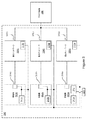
図2a−2cは、電力送達システム200の3つの実施形態を図示する。電力送達システム200は、電力をプラズマ負荷206に提供し、その場合、整合ネットワーク204は、反射電力を最小限にする。発電機202の電力出力は、第1の伝送媒体208を介して、整合ネットワーク204に、次いで、第2の伝送媒体210を介して、プラズマ負荷206に提供される。第1のセンサ214および随意の第2のセンサ218は、電圧、電流、位相、インピーダンス、および電力のうちの1つ以上を測定することによって、電力の電気特性を監視し、この情報をローカルコントローラにパス(または、中継)する。ローカルコントローラ212は、発電機202または整合ネットワーク204内(図2b参照)、あるいは電力送達システム200内の任意の場所(図2c参照)のいずれかに常駐し、発電機202、整合ネットワーク204、およびセンサ214、218のうちの1つ以上間の通信を管理する。ローカルコントローラ212はまた、ユーザと電力送達システム200の任意の構成要素との間の通信を管理することができる。ローカルコントローラ212は、迅速に調節可能であって、一定かつおよび正確な電力が、1つ以上の電力送達要件に従って、プラズマ負荷206に送達されるように、電力送達システム200を管理することができる。
FIGS. 2 a-2 c illustrate three embodiments of the
1つ以上のセンサ214、218は、ローカルコントローラ212に対する電力を監視する。特に、第1のセンサ214は、発電機202の電力出力ならびに発電機202によって経験されるインピーダンスを監視することができる。ローカルコントローラ212は、電力送達要件に照らして、第1のセンサ214(随意に、また、第2のセンサ218)によって提供される測定値を分析する。これは、電力送達要件を満たすために十分であると判断される発電機202および整合ネットワーク204のための動作パラメータを決定することができ、発電機202および整合ネットワーク204に、電力送達要件を満たすために、それらの構成要素の内部パラメータを調節するように命令する(または、命令を中継する)ことができる。
One or
この統合された電力送達システム200、すなわち、本明細書に開示されるローカルコントローラ212と第1のセンサ212(随意に、第2のセンサ218)との使用は、従来技術に勝るいくつかの利点を有する。第1に、電力送達システム200の種々の構成要素の制御および動作を統合することによって、同時に、整合ネットワーク204および発電機202を同調させる能力、あるいは発電機202の出力の波形をパルス発信または変更しながら、整合ネットワーク204を同調させる能力等、新規電力送達方法が可能となる。第2に、本システムおよびアプローチは、プラズマ負荷206に対して迅速に調節可能な、正確な一貫した電力送達を可能にする。電力送達システム200の速度は、特に、動的電力用途(例えば、パルス状発電機202の出力)において有用である。
The use of this integrated
より迅速に電力送達を調節する能力は、一部には、センサが、インピーダンスを測定する前に、最初に、周波数を測定しなければならない従来のシステムが経験する遅延の回避に起因し得る。ローカルコントローラ214は、第1のセンサ214が、インピーダンスのサンプリングを開始する前に、周波数を測定する必要がないように、第1のセンサ214に、周波数等の発電機の動作パラメータを提供する。より早期のサンプリングは、インピーダンスが、当技術分野におけるものより高速に決定され得ることを意味する。ローカルコントローラ214はまた、第1のセンサ214に、パルス発信または電力波形の変化の開始の指標を提供し、したがって、第1のセンサ214が、サンプリング開始前に、そのような変化を検出する必要性を防止することができる。これはまた、第1のセンサ214が、当技術分野におけるセンサより早くインピーダンスの測定を開始することを可能にする。
The ability to adjust power delivery more quickly may be due in part to the avoidance of delays experienced by conventional systems where the sensor must first measure frequency before measuring impedance. The
電力送達システム200はまた、4つの方法において、電力送達の精度を改善する。第1に、複数のセンサを使用して、電力およびインピーダンスを測定する場合(例えば、それぞれ、114および116)、各センサは、各センサに対して行われる較正から生じる、そのセンサに関連付けられた誤差関数を有する。単一センサ214を使用して、電力およびインピーダンスを測定することによって、単回較正のみ行われ、したがって、誤差は、ほとんど導入されない。
The
第2に、より多くのサンプリング点を有することは、インピーダンス測定を改善することができる。当技術分野では、サンプリングは、典型的には、パルスまたは発電機波形の変化が検出された後のみ、開始することができるが、本明細書では、ローカルコントローラ212は、第1のセンサ214に、パルスまたは波形変化が生じる前またはその時点におけるパルスまたは発電機202の波形の変化の開始を指示する。したがって、第1のセンサ214は、当技術分野において可能であるよりも早期にサンプリングを開始し、したがって、より正確なインピーダンス測定を可能にすることができる。
Second, having more sampling points can improve impedance measurements. In the art, sampling can typically begin only after a change in pulse or generator waveform is detected, but in this document the local controller 212 is connected to the
第3に、インピーダンスの測定は、測定されている信号の周波数に依存し、したがって、周波数を測定する際の誤差は、測定されるインピーダンスの誤差につながる。従来技術のインピーダンス測定は、多くの場合、整合ネットワーク内のセンサ(例えば、116)が、周波数を測定した後に行われ、したがって、不必要な誤差を導入する。代替として、広帯域センサを使用するとき、誤差が、周波数の関数として、広帯域センサ内のアナログ変動によって導入される。第1のセンサ214に、整合ネットワーク(例えば、104)における周波数を測定することを要求するのではなく、第1のセンサ214に、発電機202が産生している周波数を認知させることによって、第1のセンサ214は、従来技術におけるセンサよりインピーダンス測定においてほとんど誤差を経験しない。また、第1のセンサ214は、周波数を測定する必要がないため、より多くのサンプルを採取することができ、より大きなサンプルサイズは、精度を改善する。
Thirdly, the measurement of impedance depends on the frequency of the signal being measured, and thus errors in measuring frequency lead to errors in the measured impedance. Prior art impedance measurements are often made after a sensor (eg, 116) in the matching network has measured the frequency, thus introducing unnecessary errors. Alternatively, when using a broadband sensor, errors are introduced by analog variation within the broadband sensor as a function of frequency. Rather than requiring the
第4に、電力送達システム内の各構成要素(例えば、発電機202、第1のセンサ214、整合ネットワーク204、随意の第2のセンサ218)は、異なるため、電力送達システムの動作パラメータは、好ましくは、異なる構成要素が取り替えられるとき、調節される。従来の電源は、構成要素間の変動を考慮しない。対照的に、ローカルコントローラ212は、電力送達システム200の種々の構成要素を認知し、発電機202および整合ネットワーク204へのその命令を適宜調節する。
Fourth, since each component in the power delivery system (eg,
構成要素変動は、ローカルコントローラ212に対する構成要素の識別によって考慮されることができる。例えば、発電機202および整合ネットワーク204は、ブランド、モデル、製造番号、または他の識別情報を介して、ローカルコントローラ212に対してそれら自体を識別することができる。また、いくつか挙げると、ステータス、設定点、および構成等の動作特性を提供することができる。これは、それぞれ、RFエンジン213およびインピーダンス制御システム215を介して、行われることができる。第1のセンサおよび第2のセンサ214、218もまた、ローカルコントローラ212に対してそれら自体を識別することができる。認証は、認証アルゴリズムを介して行い得る。したがって、一実施形態では、伝送媒体208を介して接続された場合、発電機202および整合ネットワーク204の特定のタイプまたはブランドのみ動作可能である。ローカルコントローラ212はまた、発電機202、整合ネットワーク204、およびセンサ214、218にクエリを行い、そのユニットタイプ、製造番号、部品番号、または任意の他の識別情報を決定することができる。この知識によって、ローカルコントローラ212は、発電機202および整合ネットワーク204への命令を調整し、構成要素内の変動を考慮し、したがって、電力送達システム200が、当技術分野において可能であるより正確かつ一貫した電力を提供することを可能にすることができる。
Component variation can be accounted for by component identification to the local controller 212. For example, the
電力送達システム100はまた、電力およびインピーダンスの両方を測定する能力のため、電力送達の一貫性(または、品質)を改善する。一部には、一貫性は、前述のより高い精度を介して改善される(例えば、誤差の蓄積の低減およびより早期かつより広範なサンプリング)。従来技術は、電力送達システムの複数の制御ループ内で安定性を維持することが困難であったが、単一コントローラ214が、複数の制御ループを制御し、制御ループ間の安定性および同期を確保することができるため、一貫性もまた、改善される。
The
いくつかの設計側面は、これらの利点を可能にする。第1に、発電機202の電力出力および発電機202によって経験されるインピーダンスの両方を監視するための単一センサ214の使用である。第1のセンサ214は、発電機202の出力における電圧、電流、位相、インピーダンス、および電力を測定することができる。第1のセンサ214は、発電機202の出力に配置されることができる。第1のセンサ214は、インピーダンスを遠隔で測定する能力により、発電機202からの電力に加え、発電機202によって経験されるインピーダンスを測定することができ、これは、当技術分野では不可能な特徴である。遠隔インピーダンス測定は、第1のセンサ214から物理的に遠隔である場所(または、較正点)、例えば、第1のセンサ214から第1の伝送媒体208に沿ってある物理的距離にある場所(例えば、整合ネットワーク204の入力)において、インピーダンスを確認する。
Several design aspects enable these advantages. First, the use of a
従来のインピーダンス測定における不正確性は、インピーダンスの遠隔監視が、不可能ではないにしても、困難であったことを意味した。第1のセンサ214が、これらの課題を克服する2つの理由が存在する:(1)第1のセンサ214は、当技術分野におけるセンサより、較正インピーダンスと関連する増加する電圧定在波比に対して、よりすぐれた線形応答を有する、(2)第1のセンサ214は、発電機202出力電力の位相をより厳密に測定することができる。
Inaccuracies in traditional impedance measurements meant that remote monitoring of impedance was difficult if not impossible. There are two reasons why the
典型的には、センサは、中心動作インピーダンス(例えば、50Ω)の近くで最適に動作するように構成されることができるが、インピーダンス変動に対するその非線形応答により、インピーダンスが較正インピーダンスから離れるにつれて、センサ精度は、急激に劣化する。物理的に局所的な測定に対するこの不正確性は、大きな物理的距離にわたって測定を行うとき、増幅される。対照的に、センサ214は、電圧定在波比円上におけるよりすぐれた線形応答を有し、インピーダンス較正点から離れたインピーダンス、したがって、物理的に遠隔場所における正確なインピーダンス測定を可能にする。
Typically, the sensor can be configured to operate optimally near a central operating impedance (e.g., 50 Ω), but due to its non-linear response to impedance variations, as the impedance moves away from the calibration impedance, the sensor The accuracy deteriorates rapidly. This inaccuracy for physically local measurements is amplified when taking measurements over large physical distances. In contrast,
加えて、第1のセンサ214は、以前の世代のセンサにおいて可能であったよりも、発電機202の出力の位相を厳密に測定することができる。特に、高位相角度において、位相角度測定精度に対して、したがって、結果として生じるインピーダンスおよび電力測定において、極端に感受性が高い。第1のセンサ214は、より正確に、位相角度を測定することができるため、インピーダンスを遠隔でより良好に測定可能である。
In addition, the
ある実施形態では、第1のセンサ214は、方向性連結器である。方向性連結器は、順方向および逆方向電力のスケーリングされた電力ならびにそれらの間の位相差異を測定することができる。方向性連結器は、次いで、スケーリングされた電力および位相差異をローカルコントローラ212に戻すことができる。スケーリングされた電力は、方向性連結器が測定システムに提供する電圧であり、その公称負荷条件(例えば、50Ω)に動作する発電機202の出力電圧に比例する。
In some embodiments, the
前述の利点は、第2に、単一ローカルコントローラ212を通した、電力送達システム200の統合された制御および監視によって可能にされる。ローカルコントローラ212は、発電機202、整合ネットワーク204、第1のセンサ214、および随意の第2のセンサ218から情報を受信し、それを分析することができる。ローカルコントローラ212は、1つ以上のアルゴリズムを起動し、電力送達システム200に関して受信した情報を分析し、プラズマ負荷206への一貫した電力送達を確保するために、行うべき手順を決定し得る。ローカルコントローラ212はまた、ある作用および手順を実施するために、発電機202および整合ネットワーク204等の電力送達システム200内の他の構成要素に対する命令を発行することができる。
The aforementioned advantages are secondly enabled by the integrated control and monitoring of the
ローカルコントローラ212が、全測定を監視し、全制御信号および命令を配信するため、オペレータの責任の多くは、軽減され、発電機202および整合ネットワーク204が、電力およびインピーダンス変動に順応する速度は、向上される。そのような構成はまた、導線および信号線が、ほとんど要求されないため、電力送達システム200のハードウェア要件を簡略化する。導線および信号線の数を最小限にすることによって、発電機202および整合ネットワーク204は、より小型かつあまり複雑ではないソフトウェアおよびファームウェアを介して、制御されることができる。
Because the local controller 212 monitors all measurements and distributes all control signals and instructions, much of the operator's responsibility is mitigated and the speed at which the
ローカルコントローラ212は、発電機202および整合ネットワーク204の両方の動作を管理するため、それらの構成要素の同時同調が可能である。ローカルコントローラ212は、発電機202のRFエンジン213に、発電機202の電力出力の振幅、搬送周波数、電力周波数、パルス幅、パルスデューティサイクル、または波形を調節するように命令することができる。ローカルコントローラ212はまた、整合ネットワーク204のインピーダンス制御システム215に、例えば、モータ駆動ボードに、整合ネットワーク104の可変キャパシタを調節させることによって、整合ネットワーク212のインピーダンスを調節するように命令することができる。
The local controller 212 manages the operation of both the
利用可能な同調選択肢は、ローカルコントローラ212が、どのように電力送達システム200を管理するかを指図することができる。発電機202の周波数が固定される場合、ローカルコントローラ212は、命令を整合ネットワーク204にパスし、インピーダンスを調節することができる。発電機202の周波数が可変である場合、ローカルコントローラ212は、(1)命令を整合ネットワーク204にパスし、発電機202が経験するインピーダンスを変更すること、(2)命令を発電機202にパスし、電力出力周波数を変更すること、または(3)命令を整合ネットワーク204にパスし、発電機202が経験するインピーダンスを変更し、命令を発電機202にパスし、その電力出力周波数を変更することができる。発電機202の周波数は、整合ネットワーク204のインピーダンスより迅速に調節されるため、整合ネットワーク204のインピーダンス調節に加え、またはその代わりに、発電機202に、周波数を介して、同調させるように構成することは、高速同調が要求される場合、好ましくあり得る。言い換えると、インピーダンス整合は、発電機202および整合ネットワーク204の同時同調を介して、行われることができる。
The available tuning options can dictate how the local controller 212 manages the
ローカルコントローラ212が、随意の第2のセンサ218によって提供される情報を考慮する場合、より一貫し、かつ正確な電力が、送達され得る。例えば、随意の第2のセンサ218は、プラズマ負荷206に送達される電力を特性化するデータを提供し、したがって、ローカルコントローラ212が、より正確かつ一貫して、同調命令を発電機202および整合ネットワーク204に提供することを可能にすることができる。随意の第2のセンサ218からの測定はまた、チャンバ整合のために使用され、並行して動作するチャンバ間の一貫した電力送達を改善することができる(各チャンバは、異なる電力送達システムを有する)。ローカルコントローラ212はまた、これらの測定を使用して、ウエハ間の一貫性、ウエハ表面にわたる均一処理、終点検出(例えば、プラズマからの光放出の監視を介して)、およびアーク管理を改善することができる。図示されないが、いくつかの実施形態では、随意の第2のセンサ218は、プラズマチャンバ内に、またはウエハと接触して、配置されることができる。
If the local controller 212 considers the information provided by the optional second sensor 218, more consistent and accurate power can be delivered. For example, the optional second sensor 218 provides data characterizing the power delivered to the
ある実施形態では、プラズマ負荷206に提供される電力は、種々の設定点(例えば、第1の設定点から第2の設定点)に対して変更され得る。整合ネットワーク204は、発電機202が、電力設定点間で切り替わる場合、プラズマ負荷206への一貫した電力送達を維持するために十分に高速に調節可能ではない場合がある。この課題を克服するために、試運転を使用して、各発電機202の設定点に対応する好ましい整合ネットワーク204の設定点を決定することができる。試運転は、処理されるべき素子、半導体、または任意の他の物体が、プラズマチャンバ内に設置される前に生じる。整合ネットワーク204および発電機202は、次いで、種々の発電機202の設定点に対して同調される。同調され得るパラメータとして、発電機202の周波数、パルス幅、および整合ネットワーク204のインピーダンスが挙げられる。この同調は、チャンバ内の素子に害を及ぼすことなく、低速同調が生じ得るように、チャンバ内に何も伴わずに実施される。種々の発電機202の設定点に対して好ましいことが決定されたパラメータは、メモリ内に記憶されることができる。実際のプラズマ処理中、ローカルコントローラ212は、発電機202および整合ネットワーク204に対して命令を発行し、種々の設定点に関連付けられた好ましいパラメータで動作させることができる。このように、整合ネットワーク204および発電機202は、処理中、同調する必要がなく、むしろ、試運転で決定されるような好ましいパラメータに迅速に設定されることができる。
In certain embodiments, the power provided to the
ローカルコントローラ212はまた、電力送達システム200を特徴づける、以下の非限定的側面を考慮することができる:構成要素効率特性、制御アルゴリズムパラメータ、整合ネットワーク204内の可変キャパシタ位置、故障および警告等の診断、構成要素健全性基準、構成要素履歴ログ、および構成要素ステータス要求。
The local controller 212 may also consider the following non-limiting aspects that characterize the power delivery system 200: component efficiency characteristics, control algorithm parameters, variable capacitor location within the
ローカルコントローラ212はまた、発電機202および整合ネットワーク204の動作を管理する場合、プラズマ負荷206の非電気特性を考慮することができる。例えば、ローカルコントローラ212aは、非限定的実施例をいくつか挙げると、チャンバ圧力、チャンバ内のガスの化学的性質、プラズマのイオンエネルギー、プラズマの光強度、プラズマによって放出される光のスペクトル成分、およびプラズマアーク放電を考慮することができる。ある実施形態では、随意の第2のセンサ218は、非限定的実施例をいくつか挙げると、チャンバ圧力、チャンバ内のガスの化学的性質、プラズマのイオンエネルギー、プラズマの光強度、プラズマによって放出される光のスペクトル成分、およびプラズマアーク放電等のプラズマ負荷206またはプラズマ処理チャンバ(図示せず)の非電気特性を監視することができる。
The local controller 212 can also take into account the non-electrical characteristics of the
図示されるように、ローカルコントローラ212は、電力送達システム200とのユーザ相互作用のための単独の導管である。一実施形態では、ユーザは、ローカルコントローラ212と通信する外部コントローラ220とインターフェースをとることができる。発電機202および整合ネットワーク204のユーザ制御は、外部コントローラ220を経由して、ローカルコントローラ212を介して、行われる。しかしながら、当業者は、電力送達システムとのユーザ相互作用は、必ずしも、ローカルコントローラ212に限定されないことを認識するであろう。
As shown, local controller 212 is a single conduit for user interaction with
第1のセンサ214は、随意に、随意の第2のセンサ218(または、負荷センサ)とともに実装されることができる。随意の第2のセンサ218は、整合ネットワーク204の出力(218a)に、または整合ネットワーク204とプラズマ負荷206との間かつそれらを含むある場所(218b)に配置されることができる。随意の第2のセンサ218は、プラズマ負荷206に送達される電力を特性化するように構成され、整合ネットワーク204の出力または整合ネットワーク204とプラズマ負荷206との間の任意の場所における、電圧、電流、位相、インピーダンス、または電力を測定することができる。ある実施形態では、随意の第2のセンサ218は、プラズマ負荷206に連結されることができ、処理中、プラズマ処理チャンバ内に連結される、または、ウエハに連結されることができる。
The
ローカルコントローラ212は、発電機202(特に、RFエンジン213)、第1のセンサ214、整合ネットワーク204(特に、インピーダンス制御システム215)、および随意の第2のセンサ218の間、それ自体とこれらの構成要素との間、ならびにこれらの構成要素とユーザとの間の通信を管理すること(例えば、外部コントローラ220を介して)ができる。これらの通信は、それぞれ、発電機202および整合ネットワーク204内部の信号経路225aまたは225bを介して、あるいは、概して、発電機202および整合ネットワーク204の外部(但し、発電機202および整合ネットワーク204の内部の一部を含むことができる)の信号経路226を介して、行われることができる。
The local controller 212 includes itself and these between the generator 202 (particularly the RF engine 213), the
図示される実施形態では、信号経路226は、バスである(信号は、両方向に進行することができ、複数の信号が、同一の経路に沿って進行することができる)。しかしながら、他の実施形態では、種々の構成要素は、ローカルコントローラ212へのそれらの独自の信号経路を有することができる。他の実施形態では、2つ以上のバスタイプ信号経路が存在することができ、さらに他の実施形態では、バス様および非バスの信号経路の組み合わせであることができる。
In the illustrated embodiment, the
いくつかの実施形態では、信号経路226は、伝送媒体208を介した信号によって置換されることができる。言い換えると、随意の第2のセンサ218からローカルコントローラ212への通信は、発電機202と整合ネットワーク204との間で伝送される電力信号上で変調されることができる。図示される種々の構成要素間の通信は、RS−485等のシリアル通信プロトコルを介することができる。代替として、これらの通信のうちの1つ以上は、無線接続を介して、あるいは有線または無線ネットワークを介して、行われることができる。例えば、信号経路226は、ローカルエリアネットワーク(LAN)として実装されることができる。
In some embodiments, the
図2bを参照すると、ローカルコントローラ212bは、電力送達システム200内に配置されるが、発電機202または整合ネットワーク204の一部ではないか、またはそれに接続されない。ローカルコントローラ212bは、バスとして構成される、信号経路226を介して、種々の構成要素と通信することができる。再び、バス構成は、必須ではなく、各構成要素は、ローカルコントローラ212bへの分離された信号経路を有することができる。
Referring to FIG. 2b, the
図2cでは、ローカルコントローラ212cは、整合ネットワーク204に連結される、またはその一部である。再び、バスタイプ信号経路または分離された信号経路の任意の組み合わせが、使用されることができる。図示されるように、第1の位置218aにおける随意の第2のセンサ218およびインピーダンス制御システム215は、整合ネットワーク204の内部の信号経路625bを介して、ローカルコントローラ212cと通信することができる。発電機202(特に、RFエンジン213)、第1のセンサ214、および代替位置218bにおける随意の第2のセンサ218は、バス構成における信号経路226を介して、ローカルコントローラ212cと通信する。
In FIG. 2c, the
ローカルコントローラ212、RFエンジン213、第1のセンサ214、インピーダンス制御システム215、および随意の第2のセンサ218は、限定されないが、中央処理ユニット(CPU)、フィールドプログラマブルゲートアレイ(FPGA)、プログラマブル論理素子(PLD)、デジタル信号プロセッサ(DSP)、または1つ以上のCPU、FPGA、PLD、および/またはDSPの組み合わせ等、任意のプロセッサを含むことができる。これらの構成要素のいずれも、その独自のメモリまたは共有メモリを含む、またはそれと通信することができ、その場合、メモリは、発電機202および整合ネットワーク204の構成またはプラズマ負荷206に伝送される電力の傾向等の情報を記憶するように構成することができる。メモリは、ローカルコントローラ212の一部であることができる、あるいは発電機202または整合ネットワーク204のいずれかの一部であることができる。ある実施形態では、メモリは、RFエンジン213またはインピーダンス制御システム215の一部であることができる。
Local controller 212,
ローカルコントローラ212は、ハードウェア、ソフトウェア、ファームウェア、またはこれらの組み合わせを含むことができる。例えば、ローカルコントローラ212は、第1のセンサおよび第2のセンサ214、218からのデータを分析し、発電機202および整合ネットワーク204に、それらの構成要素の内部パラメータを調節するように命令する方法および命令すべき時を決定するように構成される、プロセッサ上で起動するプロセッサ、メモリ、およびソフトウェアを含むことができる。
The local controller 212 can include hardware, software, firmware, or a combination thereof. For example, the local controller 212 analyzes the data from the first and
RFエンジン213、第1のセンサ214、インピーダンス制御システム215、および随意の第2のセンサ218は、各々、命令を受信し、情報をローカルコントローラ212に伝送するプロセッサ等の論理を含むことができる。代替として、ローカルコントローラ212は、全論理を処理し、RFエンジン213、第1のセンサ214、インピーダンス制御システム215、および随意の第2のセンサ218の各々に対する機能を制御することができる。
The
電力送達要件は、ローカルコントローラ212内にプログラムされること、ローカルコントローラ212によってアクセス可能なメモリ上に常駐すること、またはユーザによって提供されることができる(ユーザ電力送達要件)。ある実施形態では、第1のセンサおよび第2のセンサ214、218は、V−Iセンサ(電圧、電流、および位相を測定可能)または位相を測定可能な方向性連結器のいずれかである。実際は、その2つの第2のセンサ218の位置(218aまたは218b)のうちの1つのみが、実装される。
The power delivery requirements can be programmed into the local controller 212, can reside on memory accessible by the local controller 212, or can be provided by the user (user power delivery requirements). In some embodiments, the first and
伝送媒体208、210は、高電力ケーブルまたは伝送線として実装されることができる。それらはまた、隣接または接続される発電機202と整合ネットワーク204との間の電気接続であることができる。ある実施形態では、伝送媒体208が、単に、電力送達システム200の2つの下位構成要素間の内部電気接続であるように、発電機202は、統合された電力送達システム200の一部として、整合ネットワーク204に接続される。別の実施形態では、発電機202と整合ネットワーク204とは、伝送媒体208が存在しないように相互接続される。言い換えると、発電機202と整合ネットワーク204とは、単一ボックス、容器、パッケージ、またはユニットの一部であることができる。そのような実施形態は、下位構成要素(例えば、いくつか挙げると、電源、メモリ、およびプロセッサ)のより大きな統合と、発電機202と整合ネットワーク204との間の通信とを伴い得る。発電機202および整合ネットワーク204内のいくつかの下位構成要素は、共有されることができる。例えば、整合ネットワーク204は、発電機202および整合ネットワーク204の両方が、発電機202のフィルタおよび/または最終結合器を共有し得る、発電機202の一体部分のように作製され得る。
ある実施形態では、電力制御システムは、ローカルコントローラ212と、第1のセンサ214と、随意に、第2のセンサ218とを含むことができる。電力制御システムを使用して、前述のように、既存の電力送達システムを修正し、その電力送達能力を向上させることができる。
In certain embodiments, the power control system can include a local controller 212, a
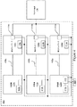
図3は、多重発電機電力送達システム300の実施形態を図示する。電力送達システム300は、発電機302a、302b、302cが、電力をプラズマ負荷306に提供するにつれて、各々が反射される電力を最小限にするために使用される、整合ネットワーク304a、304b、304cを伴う、3つの発電機302a、302b、302cを含む。センサ314a、314b、314cは、発電機302a、302b、302cの電圧、電流、位相、インピーダンス、および電力を監視するために含まれる。センサ314a、314b、314cは、各発電機302a、302b、302cの一部であるか、または、各発電機302a、302b、302cに連結されるかまたは各発電機302a、302b、302cの外部であることができる。センサ314a、314b、314cは、電圧、電流、位相、電力、およびインピーダンス測定値をローカルコントローラ312に中継する。
FIG. 3 illustrates an embodiment of a multiple generator
センサ314a、314b、314cはまた、ローカルコントローラ312に、構成および動作パラメータ等の情報を含む、それ自体の識別を中継することができる。発電機302a、302b、302cおよび整合ネットワーク315a、315b、315cはまた、それぞれ、例えば、RFエンジン313a、313b、313cおよびインピーダンス制御システム315a、315b、315cを介して、ローカルコントローラ312に対してそれ自体を識別することができる。
The
ローカルコントローラ312は、発電機302a、302b、302c、整合ネットワーク304a、304b、304c、およびセンサ314a、314b、314c間の通信を管理することができる。ローカルコントローラ312はまた、内部パラメータを調節する方法および調節すべき時に関する命令を、発電機302a、302b、302cおよび整合ネットワーク304a、304b、304cにパスするように構成される。このように、ローカルコントローラ312は、発電機302a、302b、302cおよび整合ネットワーク304a、304b、304cが、統合して、かつ構成要素間の変動ならびに他の構成要素の動作を考慮するように、動作することを可能にする。いくつかの事例では、電力送達システム300のこの統合された動作はまた、プラズマチャンバガスの化学的性質または処理終点等の非電気的要因を考慮することができる。ある実施形態では、発電機302a、302b、302cの周波数は、整合ネットワーク304a、304b、304cも同調させながら、同調されることができる。
The
この多重発電機実施形態では、各発電機302a、302b、302cは、伝送媒体310a、310b、310cまたはプラズマ負荷306(構成に応じて)を通して、他の発電機302a、302b、302cを認識するので、当技術分野における特定の課題は、一貫した電力の生成である。言い換えると、従来の多重発電機システムは、発電機302a、302b、302c間のクロストーク相互作用によって悩まされる。発電機302a、302b、302cおよび整合ネットワーク304a、304b、304cが、ローカルコントローラ312を介して、相互に通信し、これらの構成要素の全部の動作を考慮して、ローカルコントローラ312によって制御されることを可能にすることによって、同時に、一貫し、かつ正確な電力が、プラズマ負荷306に提供されることができる。
In this multiple generator embodiment, each
ある実施形態では、ユーザは、ローカルコントローラ312と通信する外部コントローラ320とインターフェースをとることができる。外部コントローラ320は、ローカルコントローラ412へおよびそこから、命令とデータの両方を送受信することができる。発電機302a、302b、302cおよび整合ネットワーク304a、304b、304cのユーザ制御は、外部コントローラ320を経由して、ローカルコントローラ312を介して行われる。
In some embodiments, the user can interface with an
ローカルコントローラ312は、発電機302aの一部として図示されるが、また、発電機302bまたは発電機302cの一部であることもできる。代替として、電力送達システム300内のあらゆる他の場所もまた、使用されることができる。
Although the
さらに、ローカルコントローラ312は、各発電機302a、302b、302cのRFエンジン313a、313b、313cおよび各整合ネットワーク304a、304b、304cのインピーダンス制御システム315a、315b、315cと通信することができる。特に、ローカルコントローラ312は、これらの下位構成要素と通信し、命令をパスすることができる。このように、ローカルコントローラ312は、発電機302a、302b、302cおよび整合ネットワーク304a、304b、304cに、2つの非限定的実施例を挙げると、パルス周波数および可変キャパシタ位置等の動作パラメータを変更するように命令することができる。
Further, the
図4は、多重発電機電力送達システム400の別の実施形態を図示する。図4は、センサ414a、414b、414cが、発電機の出力402a、402b、402cの代わりに、整合ネットワーク404a、404b、404cの出力に配置されるという点において、図3と異なる。センサ414a、414b、414cは、整合ネットワーク404a、404b、404cの出力において、またはプラズマ負荷406への途中において、電圧、電流、位相、インピーダンス、および/または電力を測定することによって、各発電機402a、402b、402cおよび整合ネットワーク404a、404b、404cに対する電力を特徴づけるように構成される。
FIG. 4 illustrates another embodiment of a multiple generator
センサ414a、414b、414cおよび発電機402a、402b、402cは、それぞれ、RFエンジンおよびインピーダンス制御システム415a、415b、415cを介して、ローカルコントローラ412に対してそれ自体を識別することができる。
電力送達システム400は、外部コントローラ420を介して、ユーザとインターフェースをとることができる。外部コントローラ420は、ローカルコントローラ412と通信し、ローカルコントローラ412へおよびそこから、命令とデータの両方を送受信することができる。
The
前述の実施形態におけるように、ローカルコントローラ412は、図示されるように、発電機402aの一部として、あるいは、電力送達システム400内にある他の構成要素のいずれかの一部として、または、これらの構成要素のいずれかに隣接し、依然として電力送達システム400内に配置されることができる。
As in the previous embodiment, the
インピーダンス制御システム415a、415b、415cは、各整合ネットワーク404a、404b、404cに対して図示されるが、当業者は、これらが、別個のハードウェア(または、ソフトウェアまたはファームウェア)構成要素、または各整合ネットワーク404a、404b、404cに対して別個の論理ブロックを備えている単一ハードウェア構成要素のいずれかを表すことができることを認識するであろう。代替実施形態では、単一インピーダンス制御システム(図示せず)が、全3つの整合ネットワーク404a、404b、404cの動作パラメータを制御し得る。
Although
別の実施形態では、センサ414a、414b、414cは、整合ネットワーク404a、404b、404cとプラズマ負荷406との間に位置する、単一センサによって置換されることができる。単一センサは、図示される3つのセンサ414a、414b、414cが構成されるように、電圧、電流、位相、インピーダンス、および電力を測定することができる。
In another embodiment, the
発電機402a、402b、402cおよび整合ネットワーク404a、404b、404cは、同一の信号経路(バス構成において)を介して、ローカルコントローラ412と通信するように図示されるが、他の実施形態では、各構成要素は、ローカルコントローラへの別個の信号経路を有し得る。代替として、発電機402a、402b、402cは、ローカルコントローラ412への1つの信号経路を有し得る一方、整合ネットワーク404a、404b、404cは、ローカルコントローラ412への別の信号経路を有する。センサ414a、414b、414cはまた、ローカルコントローラ412へのそれらの独自の信号経路を有することができる。
Although the
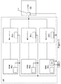
図5は、多重発電機電力送達システム500のさらに別の実施形態を図示する。図5は、それらの図のセンサが、プラズマ負荷506の入力として配置される単一センサ514によって、ここでは置換されるという点において、図3および4とは異なる。センサ514は、各発電機502a、502b、502cおよび整合ネットワーク504a、504b、504cに対する電力を特徴づけるように構成される。
FIG. 5 illustrates yet another embodiment of a multiple generator
電力送達システム500は、外部コントローラ520を介して、ユーザとインターフェースをとることができる。外部コントローラ520は、ローカルコントローラ512と通信し、ローカルコントローラ512へおよびそこから、命令とデータの両方を送受信することができる。
The
発電機502a、502b、502cおよび整合ネットワーク504a、504b、504cは、同一の信号経路(バス構成において)を介して、ローカルコントローラ512と通信するように図示されるが、他の実施形態では、各構成要素は、ローカルコントローラへの別個の信号経路を有し得る。代替として、発電機502a、502b、502cは、ローカルコントローラ512への1つの信号経路を有し得る一方、整合ネットワーク504a、504b、504cは、ローカルコントローラ512への別の信号経路を有する。センサ514a、514b、514cはまた、ローカルコントローラ512へのそれらの独自の信号経路を有することができる。
Although the
図3−5の各外部コントローラは、ローカルコントローラへのそれらの独自の信号経路を有するように図示されるが、代替実施形態では、各外部コントローラは、センサ発電機によって使用され、整合ネットワークがローカルコントローラと通信するために使用する同じ信号経路を共有することができる。 Although each external controller in FIGS. 3-5 is illustrated as having their own signal path to the local controller, in an alternative embodiment, each external controller is used by a sensor generator and the matching network is local. The same signal path used to communicate with the controller can be shared.
実施形態図3−5に図示される多重発電機は、発電機、整合ネットワーク、およびセンサの3組を示すが、他の実施形態では、これらの構成は、発電機、整合ネットワーク、およびセンサの2つ以上の組によって実装されることができる。一実施形態では、発電機および整合ネットワークの各組ごとに1つのセンサではなく、単一センサが存在することができる。単一センサは、1つの発電機に対してローカルで、2つの発電機に対して遠隔で、電力出力を測定し得る。単一センサはまた、全3つの整合ネットワークに対するインピーダンスを遠隔で特徴づけ得る。 Embodiments The multiple generators illustrated in FIGS. 3-5 show three sets of generators, matching networks, and sensors, but in other embodiments, these configurations include generators, matching networks, and sensors. It can be implemented by two or more sets. In one embodiment, there may be a single sensor rather than one sensor for each set of generator and matching network. A single sensor can measure the power output local to one generator and remote to two generators. A single sensor can also remotely characterize the impedance for all three matching networks.
図6は、本開示の一実施形態による、電力をプラズマ負荷に供給する方法600を図示する。方法600は、監視動作602、分析動作604、および中継動作606を含む。監視動作602は、発電機(例えば、202)の電力出力の電気特性を監視し、電力出力の電気特性をローカルコントローラ(例えば、212)に提供することを伴う。分析動作604は、電力出力の電気特性(例えば、電圧、電流、位相、インピーダンス、電力)を分析することを含むことができる。分析動作604はまた、電力送達システム(例えば、200)が、監視された電気特性に照らして、電力送達要件を満たすために、どのように動作され得るかを決定することを伴うことができる。中継動作606は、命令を電力送達システムの発電機および整合ネットワークに中継(パスまたは伝送)することを伴うことができ、その場合、命令は、分析動作604に基づくことができる。命令は、発電機および整合ネットワークの同時同調を可能にすることができる。
FIG. 6 illustrates a
本明細書に説明されるシステムおよび方法は、本明細書に説明される具体的物理的素子に加え、コンピュータシステム等の機械内で実装されることができる。図7は、一組の命令が、素子に、本開示の側面および/または方法論のうちの任意の1つ以上を実施あるいは実行させるために実行することができる、コンピュータシステム700の例示的形態における機械の一実施形態の概略表現を示す。図7における構成要素は、実施例にすぎず、任意のハードウェア、ソフトウェア、埋込論理構成要素、または特定の実施形態を実装する2つ以上のそのような構成要素の組み合わせの使用あるいは機能性の範囲に限定するものではない。
The systems and methods described herein can be implemented in machines such as computer systems in addition to the specific physical elements described herein. FIG. 7 is an illustration of an exemplary form of a
コンピュータシステム700は、バス740を介して、互におよび他の構成要素と通信する、プロセッサ701と、メモリ703と、記憶装置708とを含み得る。バス740はまた、ディスプレイ732、1つ以上の入力素子733(例えば、キーパッド、キーボード、マウス、スタイラス等を含み得る)、1つ以上の出力素子734、1つ以上の記憶素子735、および種々の有形記憶媒体736をリンクし得る。これらの要素はすべて、直接、あるいはバス740への1つ以上のインターフェースまたはアダプタを介して、インターフェースをとり得る。例えば、種々の有形記憶媒体736は記憶媒体インターフェース726を介して、バス740とインターフェースをとることができる。コンピュータシステム700は、1つ以上の集積回路(IC)、印刷回路基板(PCB)、モバイルハンドヘルド素子(携帯電話またはPDA等)、ラップトップまたはノートブックコンピュータ、分散型コンピュータシステム、コンピューティンググリッド、あるいはサーバを含むが、それらに限定されない、任意の好適な物理的形態を有し得る。
プロセッサ701(または、中央処理ユニット(CPU))は、随意に、命令、データ、またはコンピュータアドレスの一時的ローカル記憶のためのキャッシュメモリユニット702を含む。プロセッサ701は、コンピュータ可読命令の実行を支援するように構成される。コンピュータシステム700は、プロセッサ701が、メモリ703、記憶装置708、記憶素子735、および/または記憶媒体736等の1つ以上の有形コンピュータ可読記憶媒体において具現化されるソフトウェアを実行する結果として、機能性を提供し得る。コンピュータ可読媒体は、特定の実施形態を実装するソフトウェアを記憶し得、プロセッサ701は、ソフトウェアを実行し得る。メモリ703は、1つ以上の他のコンピュータ可読媒体(大容量記憶素子735、736等)から、またはネットワークインターフェース720等の好適なインターフェースを通して、1つ以上の他のソースから、ソフトウェアを読み取り得る。ソフトウェアは、プロセッサ701に、本明細書に説明または図示される、1つ以上のプロセスあるいは1つ以上のプロセスの1つ以上のことを実施させ得る。そのようなプロセスまたはことの実施は、メモリ703内に記憶されるデータ構造を定義し、ソフトウェアによって指示されるように、データ構造を修正することを含み得る。
The processor 701 (or central processing unit (CPU)) optionally includes a
メモリ703は、限定されないが、ランダムアクセスメモリ構成要素(例えば、RAM704)(例えば、静的RAM「SRAM」、動的RAM「DRAM」等)、読取専用構成要素(例えば、ROM705)、および任意のそれらの組み合わせを含む、種々の構成要素(例えば、機械可読媒体)を含み得る。ROM705は、データおよび命令を、単方向性に、プロセッサ701に通信するように作用し得、RAM704は、データおよび命令を、双方向性に、プロセッサ701と通信するように作用し得る。ROM705およびRAM704は、以下に説明される任意の好適な有形コンピュータ可読媒体を含み得る。一実施例では、起動の間等、コンピュータシステム700内の要素間の情報を転送するのに有用である、基本ルーチンを含む、基本入力/出力システム706(BIOS)が、メモリ703内に記憶され得る。
固定記憶装置708は、随意に、記憶制御ユニット707を通して、双方向性に、プロセッサ701に接続される。固定記憶装置708は、追加のデータ記憶容量を提供し、また、本明細書に説明される任意の好適な有形コンピュータ可読媒体を含み得る。記憶装置708を使用して、オペレーティングシステム709、EXEC710(実行可能ファイル)、データ711、APVアプリケーション712(アプリケーションプログラム)、および同等物を記憶し得る。多くの場合、常時ではないが、記憶装置708は、一次記憶装置(例えば、メモリ703)より低速の二次記憶装置媒体(ハードディスク等)である。記憶装置708はまた、光ディスクドライブ、固体メモリ素子(例えば、フラッシュベースのシステム)、または前述のいずれかの組み合わせを含むことができる。記憶装置708内の情報は、適切な場合、メモリ703内の仮想メモリとして組み込まれ得る。
一実施例では、記憶素子735は、記憶素子インターフェース725を介して、コンピュータシステム700と(例えば、外部ポートコネクタ(図示せず)を介して)可撤性にインターフェースがとられ得る。特に、記憶素子735および関連付けられた機械可読媒体は、機械可読命令、データ構造、プログラムモジュール、および/またはコンピュータシステム700のための他のデータの不揮発性ならびに/あるいは揮発性記憶装置を提供し得る。一実施例では、ソフトウェアは、完全にまたは部分的に、記憶素子735上の機械可読媒体内に常駐し得る。別の実施例では、ソフトウェアは、完全にまたは部分的に、プロセッサ701内に常駐し得る。
In one embodiment, the
バス740は、種々のサブシステムを接続する。本明細書では、バスへの言及は、必要に応じて、共通機能を果たす、1つ以上のデジタル信号線を包含し得る。バス740は、限定されないが、種々のバスアーキテクチャのいずれかを使用する、メモリバス、メモリコントローラ、周辺バス、ローカルバス、および任意のそれらの組み合わせを含む、いくつかのタイプのバス構造のうちのいずれかであり得る。限定ではなく、実施例として、そのようなアーキテクチャとして、業界標準アーキテクチャ(ISA)バス、拡張ISA(EISA)バス、マイクロチャネルアーキテクチャ(MCA)バス、ビデオエレクトロニクススタンダーズアソシエーションローカルバス(VLB)、ペリフェラルコンポーネントインターコネクト(PCI)バス、PCI−エクスプレス(PCI−X)バス、アクセラレーテッドグラフィックスポート(AGP)バス、ハイパートランスポート(HTX)バス、シリアルアドバンスドテクノロジーアタッチメント(SATA)バス、および任意のそれらの組み合わせが挙げられる。
A
コンピュータシステム700はまた、入力素子733を含み得る。一実施例では、コンピュータシステム700のユーザは、入力素子733を介して、コマンドおよび/または他の情報をコンピュータシステム700に入力し得る。入力素子733の実施例として、英数字入力素子(例えば、キーボード)、ポインティング素子(例えば、マウスまたはタッチパッド)、タッチパッド、ジョイスティック、ゲームパッド、オーディオ入力素子(例えば、マイクロホン、音声応答システム等)、光学スキャナ、動画または静止画像捕捉素子(例えば、カメラ)、および任意のそれらの組み合わせが挙げられるが、それらに限定されない。入力素子733は、限定されないが、シリアル、パラレル、ゲームポート、USB、FIREWIRE、THUNDERBOLT、または前述の任意の組み合わせを含む、種々の入力インターフェース723(例えば、入力インターフェース723)のいずれかを介して、バス740に対してインターフェースがとられ得る。
The
特定の実施形態では、コンピュータシステム700が、ネットワーク730に接続されると、コンピュータシステム700は、他の素子、具体的には、ネットワーク730に接続されたモバイル素子および企業システムと通信し得る。コンピュータシステム700へおよびそこからの通信は、ネットワークインターフェース720を通して送信され得る。例えば、ネットワークインターフェース720は、1つ以上のパケット(インターネットプロトコル(IP)パケット等)の形態において、ネットワーク730から、着信通信(他の素子からの要求または応答等)を受信し得、コンピュータシステム700は、処理のために、メモリ703内に着信通信を記憶し得る。コンピュータシステム700は、同様に、メモリ703内に、1つ以上のパケットの形態において、ネットワークインターフェース720からネットワーク730に通信される、発信通信(他の素子への要求または応答等)を記憶し得る。プロセッサ701は、処理のために、メモリ703内に記憶されたこれらの通信パケットにアクセスし得る。
In certain embodiments, when the
ネットワークインターフェース720の実施例として、ネットワークインターフェースカード、モデム、およびそれらの任意の組み合わせが挙げられるが、それらに限定されない。ネットワーク730またはネットワークセグメント730の実施例として、広域ネットワーク(WAN)(例えば、インターネット、企業ネットワーク)、ローカルエリアネットワーク(LAN)(例えば、オフィス、建物、キャンパス、または他の比較的に小さい地理的空間に関連付けられたネットワーク)、電話網、2つのコンピューティング素子間の直接接続、およびそれらの任意の組み合わせが挙げられるが、それらに限定されない。ネットワーク730等のネットワークは、有線および/または無線通信モードを採用し得る。一般に、任意のネットワークトポロジーが、使用され得る。
Examples of
情報およびデータは、ディスプレイ732を通して表示されることができる。ディスプレイ732の実施例として、液晶ディスプレイ(LCD)、有機液晶ディスプレイ(OLED)、ブラウン管(CRT)、プラズマディスプレイ、およびそれらの任意の組み合わせが挙げられるが、それらに限定されない。ディスプレイ732は、バス740を介して、プロセッサ701、メモリ703、および固定記憶装置708、ならびに入力素子733等の他の素子とインターフェースをとることができる。ディスプレイ732は、ビデオインターフェース722を介して、バス740にリンクされ、ディスプレイ732とバス740間のデータの転送は、グラフィック制御721を介して、制御されることができる。
Information and data may be displayed through
ディスプレイ732に加え、コンピュータシステム700は、限定されないが、オーディオスピーカ、プリンタ、およびそれらの任意の組み合わせを含む、1つ以上の他の周辺出力素子734を含み得る。そのような周辺出力素子は、出力インターフェース724を介して、バス740に連結され得る。出力インターフェース724の実施例として、シリアルポート、パラレル接続、USBポート、FIREWIREポート、HUNDERBOLTポート、およびそれらの任意の組み合わせが挙げられるが、それらに限定されない。
In addition to
加えて、または代替として、コンピュータシステム700は、ソフトウェアの代わりに、またはそれとともに、本明細書に説明または図示される1つ以上のプロセスまたは1つ以上のプロセスの1つ以上のことを実行するように動作し得る、回路内に有線接続または別様に具現化される論理の結果として、機能性を提供し得る。本開示におけるソフトウェアの参照は、論理を包含し得、論理の参照は、ソフトウェアを包含し得る。さらに、コンピュータ可読媒体の参照は、必要に応じて、実行のためのソフトウェアを記憶する回路(IC等)、実行のための論理を具現化するための回路、または両方を包含し得る。本開示は、ハードウェア、ソフトウェア、または両方の任意の好適な組み合わせを包含する。
Additionally or alternatively, the
結論として、本発明は、とりわけ、特に、発電およびチャンバ条件が動的である場合のプラズマ処理のために、一貫し、かつ正確な電力をプラズマ負荷に提供するためのシステムおよび方法を提供する。本明細書に開示されるシステムおよび方法のいくつかの利点として、チャンバ整合、チャンバ特徴づけ、チャンバ診断、チャンバ故障予測、およびトラブルシューティングが挙げられる。当業者であれば、本明細書で説明される実施形態によって達成されるものと実質的に同じ結果を達成するために、多数の変形例および置換が、本発明、その用途、およびその構成において行われ得ることを容易に認識できる。故に、本発明を開示された例示的形態に限定する意図は全くない。多くの変形例、修正、および代替構造は、請求項で明示されるような開示された発明の範囲および精神内にある。 In conclusion, the present invention provides a system and method for providing consistent and accurate power to a plasma load, especially for plasma processing, especially when power generation and chamber conditions are dynamic. Some advantages of the systems and methods disclosed herein include chamber alignment, chamber characterization, chamber diagnostics, chamber failure prediction, and troubleshooting. Those skilled in the art will recognize that numerous variations and permutations in the present invention, its application, and its construction have been made to achieve substantially the same results as those achieved by the embodiments described herein. It can be easily recognized what can be done. Accordingly, there is no intention to limit the invention to the disclosed exemplary forms. Many variations, modifications and alternative constructions fall within the scope and spirit of the disclosed invention as set forth in the claims.
Claims (1)
Applications Claiming Priority (2)
| Application Number | Priority Date | Filing Date | Title |
|---|---|---|---|
| US201161429472P | 2011-01-04 | 2011-01-04 | |
| US61/429,472 | 2011-01-04 |
Related Parent Applications (1)
| Application Number | Title | Priority Date | Filing Date |
|---|---|---|---|
| JP2013547731A Division JP5946227B2 (en) | 2011-01-04 | 2012-01-04 | Power delivery system, power control system, and method of delivering or controlling power |
Related Child Applications (1)
| Application Number | Title | Priority Date | Filing Date |
|---|---|---|---|
| JP2017091857A Division JP6425765B2 (en) | 2011-01-04 | 2017-05-02 | System level power delivery to plasma processing load |
Publications (2)
| Publication Number | Publication Date |
|---|---|
| JP2016149366A true JP2016149366A (en) | 2016-08-18 |
| JP6141478B2 JP6141478B2 (en) | 2017-06-07 |
Family
ID=46457699
Family Applications (3)
| Application Number | Title | Priority Date | Filing Date |
|---|---|---|---|
| JP2013547731A Active JP5946227B2 (en) | 2011-01-04 | 2012-01-04 | Power delivery system, power control system, and method of delivering or controlling power |
| JP2016053392A Active JP6141478B2 (en) | 2011-01-04 | 2016-03-17 | System-level power delivery to plasma processing loads |
| JP2017091857A Active JP6425765B2 (en) | 2011-01-04 | 2017-05-02 | System level power delivery to plasma processing load |
Family Applications Before (1)
| Application Number | Title | Priority Date | Filing Date |
|---|---|---|---|
| JP2013547731A Active JP5946227B2 (en) | 2011-01-04 | 2012-01-04 | Power delivery system, power control system, and method of delivering or controlling power |
Family Applications After (1)
| Application Number | Title | Priority Date | Filing Date |
|---|---|---|---|
| JP2017091857A Active JP6425765B2 (en) | 2011-01-04 | 2017-05-02 | System level power delivery to plasma processing load |
Country Status (4)
| Country | Link |
|---|---|
| US (2) | US9088267B2 (en) |
| JP (3) | JP5946227B2 (en) |
| KR (1) | KR101675625B1 (en) |
| WO (1) | WO2012094416A1 (en) |
Cited By (2)
| Publication number | Priority date | Publication date | Assignee | Title |
|---|---|---|---|---|
| JP2021503167A (en) * | 2017-11-15 | 2021-02-04 | ラム リサーチ コーポレーションLam Research Corporation | Systems and methods for applying frequency tuning and matching tuning for processing substrates without duplication |
| JP2022545262A (en) * | 2019-08-28 | 2022-10-26 | アプライド マテリアルズ インコーポレイテッド | Tuning method for improving plasma stability |
Families Citing this family (51)
| Publication number | Priority date | Publication date | Assignee | Title |
|---|---|---|---|---|
| CN102016882B (en) * | 2007-12-31 | 2015-05-27 | 应用识别公司 | Method, system, and computer program for identification and sharing of digital images with face signatures |
| US9088267B2 (en) * | 2011-01-04 | 2015-07-21 | Advanced Energy Industries, Inc. | System level power delivery to a plasma processing load |
| KR101303040B1 (en) * | 2012-02-28 | 2013-09-03 | 주식회사 뉴파워 프라즈마 | Method and apparatus for detecting arc in plasma chamber |
| JP6113450B2 (en) * | 2012-09-07 | 2017-04-12 | 株式会社ダイヘン | Impedance adjustment device |
| JP6084417B2 (en) * | 2012-09-28 | 2017-02-22 | 株式会社ダイヘン | Impedance adjustment device |
| CN103730316B (en) | 2012-10-16 | 2016-04-06 | 中微半导体设备(上海)有限公司 | A kind of plasma processing method and plasma treatment appts |
| US8736377B2 (en) * | 2012-10-30 | 2014-05-27 | Mks Instruments, Inc. | RF pulse edge shaping |
| US9620334B2 (en) * | 2012-12-17 | 2017-04-11 | Lam Research Corporation | Control of etch rate using modeling, feedback and impedance match |
| US9536713B2 (en) * | 2013-02-27 | 2017-01-03 | Advanced Energy Industries, Inc. | Reliable plasma ignition and reignition |
| US10821542B2 (en) | 2013-03-15 | 2020-11-03 | Mks Instruments, Inc. | Pulse synchronization by monitoring power in another frequency band |
| US9578731B2 (en) * | 2014-10-16 | 2017-02-21 | Advanced Energy Industries, Inc. | Systems and methods for obtaining information about a plasma load |
| EP3091559A1 (en) * | 2015-05-05 | 2016-11-09 | TRUMPF Huettinger Sp. Z o. o. | Plasma impedance matching unit, system for supplying rf power to a plasma load, and method of supplying rf power to a plasma load |
| US9721758B2 (en) * | 2015-07-13 | 2017-08-01 | Mks Instruments, Inc. | Unified RF power delivery single input, multiple output control for continuous and pulse mode operation |
| KR101777762B1 (en) * | 2015-09-03 | 2017-09-12 | 에이피시스템 주식회사 | Device for feeding high-frequency power and apparatus for processing substrate having the same |
| US9577516B1 (en) * | 2016-02-18 | 2017-02-21 | Advanced Energy Industries, Inc. | Apparatus for controlled overshoot in a RF generator |
| JP6157036B1 (en) * | 2016-07-08 | 2017-07-05 | 株式会社京三製作所 | High frequency power supply device and control method of high frequency power supply device |
| JP2017073770A (en) * | 2016-09-30 | 2017-04-13 | 株式会社ダイヘン | High frequency matching system |
| JP2017073772A (en) * | 2016-09-30 | 2017-04-13 | 株式会社ダイヘン | High frequency matching system |
| JP6463786B2 (en) * | 2017-01-25 | 2019-02-06 | 株式会社ダイヘン | Method for adjusting impedance of high-frequency matching system |
| US10879044B2 (en) * | 2017-04-07 | 2020-12-29 | Lam Research Corporation | Auxiliary circuit in RF matching network for frequency tuning assisted dual-level pulsing |
| US11651939B2 (en) | 2017-07-07 | 2023-05-16 | Advanced Energy Industries, Inc. | Inter-period control system for plasma power delivery system and method of operating same |
| US11615943B2 (en) | 2017-07-07 | 2023-03-28 | Advanced Energy Industries, Inc. | Inter-period control for passive power distribution of multiple electrode inductive plasma source |
| CN115662868A (en) | 2017-07-07 | 2023-01-31 | 先进能源工业公司 | Intercycle control system for plasma power delivery system and method of operating the same |
| CN111788655B (en) | 2017-11-17 | 2024-04-05 | 先进工程解决方案全球控股私人有限公司 | Spatial and temporal control of ion bias voltage for plasma processing |
| US11290080B2 (en) | 2017-11-29 | 2022-03-29 | COMET Technologies USA, Inc. | Retuning for impedance matching network control |
| US10553400B2 (en) * | 2018-03-30 | 2020-02-04 | Applied Materials, Inc. | Methods and apparatus for frequency generator and match network communication |
| US10916409B2 (en) * | 2018-06-18 | 2021-02-09 | Lam Research Corporation | Active control of radial etch uniformity |
| US11804362B2 (en) | 2018-12-21 | 2023-10-31 | Advanced Energy Industries, Inc. | Frequency tuning for modulated plasma systems |
| KR20200126177A (en) * | 2019-04-29 | 2020-11-06 | 삼성전자주식회사 | Apparatus for monitoring RF(Radio Frequency) power, and PE(Plasma Enhanced) system comprising the same apparatus |
| US11527385B2 (en) | 2021-04-29 | 2022-12-13 | COMET Technologies USA, Inc. | Systems and methods for calibrating capacitors of matching networks |
| US11114279B2 (en) | 2019-06-28 | 2021-09-07 | COMET Technologies USA, Inc. | Arc suppression device for plasma processing equipment |
| US11107661B2 (en) | 2019-07-09 | 2021-08-31 | COMET Technologies USA, Inc. | Hybrid matching network topology |
| US11596309B2 (en) | 2019-07-09 | 2023-03-07 | COMET Technologies USA, Inc. | Hybrid matching network topology |
| JP7315407B2 (en) | 2019-08-06 | 2023-07-26 | オークマ株式会社 | Machine Tools |
| US11830708B2 (en) | 2020-01-10 | 2023-11-28 | COMET Technologies USA, Inc. | Inductive broad-band sensors for electromagnetic waves |
| US11521832B2 (en) | 2020-01-10 | 2022-12-06 | COMET Technologies USA, Inc. | Uniformity control for radio frequency plasma processing systems |
| US11670488B2 (en) | 2020-01-10 | 2023-06-06 | COMET Technologies USA, Inc. | Fast arc detecting match network |
| US11887820B2 (en) | 2020-01-10 | 2024-01-30 | COMET Technologies USA, Inc. | Sector shunts for plasma-based wafer processing systems |
| JP2023512486A (en) * | 2020-01-20 | 2023-03-27 | コメット テクノロジーズ ユーエスエー インコーポレイテッド | High frequency matching network and generator |
| US11605527B2 (en) | 2020-01-20 | 2023-03-14 | COMET Technologies USA, Inc. | Pulsing control match network |
| US11373844B2 (en) | 2020-09-28 | 2022-06-28 | COMET Technologies USA, Inc. | Systems and methods for repetitive tuning of matching networks |
| KR20220067554A (en) * | 2020-11-16 | 2022-05-25 | 세메스 주식회사 | Substrate treating apparatus and impedance matching method |
| US20220359161A1 (en) * | 2021-05-07 | 2022-11-10 | Applied Materials, Inc. | Rf impedance matching networks for substrate processing platform |
| EP4105962A1 (en) * | 2021-06-17 | 2022-12-21 | Impedans Ltd | A controller for a matching unit of a plasma processing system |
| EP4105963A1 (en) * | 2021-06-17 | 2022-12-21 | Impedans Ltd | A controller for a matching unit of a plasma processing system |
| US11923175B2 (en) | 2021-07-28 | 2024-03-05 | COMET Technologies USA, Inc. | Systems and methods for variable gain tuning of matching networks |
| US11670487B1 (en) | 2022-01-26 | 2023-06-06 | Advanced Energy Industries, Inc. | Bias supply control and data processing |
| US11942309B2 (en) | 2022-01-26 | 2024-03-26 | Advanced Energy Industries, Inc. | Bias supply with resonant switching |
| WO2023167854A1 (en) * | 2022-03-03 | 2023-09-07 | COMET Technologies USA, Inc. | Retuning for impedance matching network control |
| DE102022108642A1 (en) * | 2022-04-08 | 2023-10-12 | TRUMPF Hüttinger GmbH + Co. KG | Plasma ignition detection device for connection to an impedance matching circuit for a plasma generation system |
| US11657980B1 (en) | 2022-05-09 | 2023-05-23 | COMET Technologies USA, Inc. | Dielectric fluid variable capacitor |
Family Cites Families (17)
| Publication number | Priority date | Publication date | Assignee | Title |
|---|---|---|---|---|
| JP3251087B2 (en) * | 1993-02-16 | 2002-01-28 | 東京エレクトロン株式会社 | Plasma processing equipment |
| JP2929284B2 (en) * | 1997-09-10 | 1999-08-03 | 株式会社アドテック | Impedance matching and power control system for high frequency plasma processing equipment |
| JP4088499B2 (en) * | 2002-08-28 | 2008-05-21 | 株式会社ダイヘン | Impedance matching device output end characteristic analysis method, impedance matching device, and impedance matching device output end characteristic analysis system |
| US6703080B2 (en) * | 2002-05-20 | 2004-03-09 | Eni Technology, Inc. | Method and apparatus for VHF plasma processing with load mismatch reliability and stability |
| US20040016402A1 (en) * | 2002-07-26 | 2004-01-29 | Walther Steven R. | Methods and apparatus for monitoring plasma parameters in plasma doping systems |
| KR100877304B1 (en) * | 2003-11-27 | 2009-01-09 | 가부시키가이샤 다이헨 | High-Frequency Power Supply System |
| US7169256B2 (en) * | 2004-05-28 | 2007-01-30 | Lam Research Corporation | Plasma processor with electrode responsive to multiple RF frequencies |
| JP4739793B2 (en) * | 2005-03-31 | 2011-08-03 | 株式会社ダイヘン | High frequency power supply |
| US7764140B2 (en) * | 2005-10-31 | 2010-07-27 | Mks Instruments, Inc. | Radio frequency power delivery system |
| US20080179948A1 (en) * | 2005-10-31 | 2008-07-31 | Mks Instruments, Inc. | Radio frequency power delivery system |
| WO2007053569A1 (en) * | 2005-10-31 | 2007-05-10 | Mks Instruments, Inc. | Radio frequency power delivery system |
| JP2007336148A (en) * | 2006-06-14 | 2007-12-27 | Daihen Corp | Electrical property adjusting device |
| JP2007313432A (en) | 2006-05-25 | 2007-12-06 | Nippon Kankyo Calcium Kenkyusho:Kk | Equipment at embankment covering waste disposal site |
| JP2008157906A (en) * | 2006-12-25 | 2008-07-10 | Adtec Plasma Technology Co Ltd | Output impedance detection method and impedance sensor using this method, electric power monitor in load side connected high frequency electric source and control device for high frequency electric source |
| WO2009140371A2 (en) | 2008-05-14 | 2009-11-19 | Applied Materials, Inc. | Method and apparatus for pulsed plasma processing using a time resolved tuning scheme for rf power delivery |
| US8040068B2 (en) * | 2009-02-05 | 2011-10-18 | Mks Instruments, Inc. | Radio frequency power control system |
| US9088267B2 (en) * | 2011-01-04 | 2015-07-21 | Advanced Energy Industries, Inc. | System level power delivery to a plasma processing load |
-
2012
- 2012-01-04 US US13/343,576 patent/US9088267B2/en not_active Expired - Fee Related
- 2012-01-04 WO PCT/US2012/020219 patent/WO2012094416A1/en active Application Filing
- 2012-01-04 JP JP2013547731A patent/JP5946227B2/en active Active
- 2012-01-04 KR KR1020137019332A patent/KR101675625B1/en active IP Right Grant
-
2015
- 2015-06-16 US US14/740,955 patent/US9478397B2/en active Active
-
2016
- 2016-03-17 JP JP2016053392A patent/JP6141478B2/en active Active
-
2017
- 2017-05-02 JP JP2017091857A patent/JP6425765B2/en active Active
Cited By (5)
| Publication number | Priority date | Publication date | Assignee | Title |
|---|---|---|---|---|
| JP2021503167A (en) * | 2017-11-15 | 2021-02-04 | ラム リサーチ コーポレーションLam Research Corporation | Systems and methods for applying frequency tuning and matching tuning for processing substrates without duplication |
| JP7210579B2 (en) | 2017-11-15 | 2023-01-23 | ラム リサーチ コーポレーション | Systems and methods for non-overlapping application of frequency tuning and match tuning for processing substrates |
| JP2022545262A (en) * | 2019-08-28 | 2022-10-26 | アプライド マテリアルズ インコーポレイテッド | Tuning method for improving plasma stability |
| JP7318114B2 (en) | 2019-08-28 | 2023-07-31 | アプライド マテリアルズ インコーポレイテッド | Tuning method for improving plasma stability |
| US11929236B2 (en) | 2019-08-28 | 2024-03-12 | Applied Materials, Inc. | Methods of tuning to improve plasma stability |
Also Published As
| Publication number | Publication date |
|---|---|
| JP2014508378A (en) | 2014-04-03 |
| US9088267B2 (en) | 2015-07-21 |
| US20130002136A1 (en) | 2013-01-03 |
| KR101675625B1 (en) | 2016-11-22 |
| KR20130133815A (en) | 2013-12-09 |
| WO2012094416A1 (en) | 2012-07-12 |
| JP5946227B2 (en) | 2016-07-05 |
| US20150279625A1 (en) | 2015-10-01 |
| US9478397B2 (en) | 2016-10-25 |
| JP6425765B2 (en) | 2018-11-21 |
| JP6141478B2 (en) | 2017-06-07 |
| JP2017188464A (en) | 2017-10-12 |
Similar Documents
| Publication | Publication Date | Title |
|---|---|---|
| JP6141478B2 (en) | System-level power delivery to plasma processing loads | |
| TWI677265B (en) | Apparatus for frequency tuning in a rf generator | |
| US20160268100A1 (en) | Methods and apparatus for synchronizing rf pulses in a plasma processing system | |
| KR100945829B1 (en) | Plasma processing apparatus, radio frequency generator and correction method therefor | |
| US20210202209A1 (en) | Integrated control of a plasma processing system | |
| TW202103211A (en) | Detection of damage in matching networks | |
| CN106462115B (en) | Control arragement construction, control system and high-frequency energy generation device | |
| US10109460B2 (en) | Universal non-invasive chamber impedance measurement system and associated methods | |
| CN102473631B (en) | Methods and arrangements for in-situ process monitoring and control for plasma processing tools | |
| KR20240005803A (en) | System and method for iterative tuning of matching network | |
| US9412670B2 (en) | System, method and apparatus for RF power compensation in plasma etch chamber | |
| US11062065B2 (en) | Method and apparatus for obtaining matching process results among multiple reaction chambers | |
| TW202310681A (en) | Systems and methods for variable gain tuning of matching networks | |
| TW202236349A (en) | Systems and methods combining match networks and frequency tuning | |
| US20230115942A1 (en) | Substrate processing system, information processing apparatus, and information processing method | |
| KR102117099B1 (en) | Apparatus for processing substrate | |
| TW202249059A (en) | Integrated control of a plasma processing system | |
| CN117761389A (en) | Circuit board calibration method, device and storage medium |
Legal Events
| Date | Code | Title | Description |
|---|---|---|---|
| TRDD | Decision of grant or rejection written | ||
| A01 | Written decision to grant a patent or to grant a registration (utility model) |
Free format text: JAPANESE INTERMEDIATE CODE: A01 Effective date: 20170403 |
|
| A61 | First payment of annual fees (during grant procedure) |
Free format text: JAPANESE INTERMEDIATE CODE: A61 Effective date: 20170502 |
|
| R150 | Certificate of patent or registration of utility model |
Ref document number: 6141478 Country of ref document: JP Free format text: JAPANESE INTERMEDIATE CODE: R150 |
|
| S111 | Request for change of ownership or part of ownership |
Free format text: JAPANESE INTERMEDIATE CODE: R313113 |
|
| R350 | Written notification of registration of transfer |
Free format text: JAPANESE INTERMEDIATE CODE: R350 |
|
| R250 | Receipt of annual fees |
Free format text: JAPANESE INTERMEDIATE CODE: R250 |
|
| R250 | Receipt of annual fees |
Free format text: JAPANESE INTERMEDIATE CODE: R250 |
|
| R250 | Receipt of annual fees |
Free format text: JAPANESE INTERMEDIATE CODE: R250 |
|
| R250 | Receipt of annual fees |
Free format text: JAPANESE INTERMEDIATE CODE: R250 |