US11651939B2 - Inter-period control system for plasma power delivery system and method of operating same - Google Patents
Inter-period control system for plasma power delivery system and method of operating same Download PDFInfo
- Publication number
- US11651939B2 US11651939B2 US17/220,530 US202117220530A US11651939B2 US 11651939 B2 US11651939 B2 US 11651939B2 US 202117220530 A US202117220530 A US 202117220530A US 11651939 B2 US11651939 B2 US 11651939B2
- Authority
- US
- United States
- Prior art keywords
- period
- generator
- controller
- power
- impedance
- Prior art date
- Legal status (The legal status is an assumption and is not a legal conclusion. Google has not performed a legal analysis and makes no representation as to the accuracy of the status listed.)
- Active, expires
Links
Images


Classifications
-
- H—ELECTRICITY
- H01—ELECTRIC ELEMENTS
- H01J—ELECTRIC DISCHARGE TUBES OR DISCHARGE LAMPS
- H01J37/00—Discharge tubes with provision for introducing objects or material to be exposed to the discharge, e.g. for the purpose of examination or processing thereof
- H01J37/32—Gas-filled discharge tubes
- H01J37/32009—Arrangements for generation of plasma specially adapted for examination or treatment of objects, e.g. plasma sources
- H01J37/32082—Radio frequency generated discharge
- H01J37/32174—Circuits specially adapted for controlling the RF discharge
- H01J37/32183—Matching circuits
-
- H—ELECTRICITY
- H01—ELECTRIC ELEMENTS
- H01J—ELECTRIC DISCHARGE TUBES OR DISCHARGE LAMPS
- H01J37/00—Discharge tubes with provision for introducing objects or material to be exposed to the discharge, e.g. for the purpose of examination or processing thereof
- H01J37/32—Gas-filled discharge tubes
- H01J37/32009—Arrangements for generation of plasma specially adapted for examination or treatment of objects, e.g. plasma sources
- H01J37/32082—Radio frequency generated discharge
- H01J37/32128—Radio frequency generated discharge using particular waveforms, e.g. polarised waves
-
- H—ELECTRICITY
- H01—ELECTRIC ELEMENTS
- H01J—ELECTRIC DISCHARGE TUBES OR DISCHARGE LAMPS
- H01J37/00—Discharge tubes with provision for introducing objects or material to be exposed to the discharge, e.g. for the purpose of examination or processing thereof
- H01J37/32—Gas-filled discharge tubes
- H01J37/32009—Arrangements for generation of plasma specially adapted for examination or treatment of objects, e.g. plasma sources
- H01J37/32082—Radio frequency generated discharge
- H01J37/32137—Radio frequency generated discharge controlling of the discharge by modulation of energy
- H01J37/32146—Amplitude modulation, includes pulsing
-
- H—ELECTRICITY
- H01—ELECTRIC ELEMENTS
- H01J—ELECTRIC DISCHARGE TUBES OR DISCHARGE LAMPS
- H01J37/00—Discharge tubes with provision for introducing objects or material to be exposed to the discharge, e.g. for the purpose of examination or processing thereof
- H01J37/32—Gas-filled discharge tubes
- H01J37/32917—Plasma diagnostics
- H01J37/3299—Feedback systems
-
- H—ELECTRICITY
- H03—ELECTRONIC CIRCUITRY
- H03H—IMPEDANCE NETWORKS, e.g. RESONANT CIRCUITS; RESONATORS
- H03H7/00—Multiple-port networks comprising only passive electrical elements as network components
- H03H7/38—Impedance-matching networks
- H03H7/40—Automatic matching of load impedance to source impedance
Definitions
- aspects of the present disclosure relate to improved methods and systems for controlling a power delivery system, and particularly for controlling a plasma power delivery system.
- a drive for ever shrinking chip features poses significant challenges for the semiconductor industry. Requirements such as reduced plasma damage, thinner layers, shorter processing times, etc. demand higher sophistication in tool and process development. As an example, significant advances in etch processes have been enabled by multi-generator synchronized pulsing.
- Chips are often fabricated via plasma processing systems that deposit thin films on a substrate using processes such as chemical vapor deposition (CVD) and physical vapor deposition (PVD) as well to remove films from the substrate using etch processes.
- the plasma is often created by coupling radio frequency (RF) or direct current (DC) generators to a plasma chamber filled with gases injected into the plasma chamber at low pressure.
- RF radio frequency
- DC direct current
- a generator delivers RF power to an antenna in the plasma chamber, and power delivered at the antenna ignites and sustains a plasma.
- the RF generator is coupled to an impedance matching network that may match the plasma impedance to a desired impedance, typically 50 ⁇ , at the generator output.
- DC power is typically coupled to chamber via one or more electrodes.
- Modulation of the power delivered to the plasma system is often required.
- Most modulation schemes are repetitive, i.e., the same modulation waveform is repeated at a waveform repetition rate.
- the associated waveform repetition period is equal to one divided by the waveform repetition rate.
- the ability to follow a prescribed modulation waveform using a traditional control scheme requires high bandwidth from the controller and ultimately from the measurement system.
- Many plasma systems have power applied to the plasma at different frequencies.
- the nonlinear nature of the plasma load creates intermodulation products that can interfere with a generator's measurements system. Thus, it is sometimes advantageous to use a narrowband measurement system to limit such interference.
- power delivered to the plasma load is not the only parameter that is being controlled.
- the impedance presented to the generator by the plasma load can be controlled, either through controlling the frequency of the generator output or through controlling a variable impedance match network between the generator and the plasma load.
- generator source impedance may also be controlled. Tracking and controlling power in light of these various issues presents ever greater control challenges.
- a human operator typically monitors multiple sensor outputs from a generator and a match network and adjusts numerous parameters in an imperfect and relatively slow attempt to maintain consistent power delivery to the plasma load.
- the operator may interact with an external controller that collects information from the various components of the system, displays this information for the operator, and transmits commands from the operator to the various components of the system.
- etch processes have been enabled by the introduction of a generation of RF power supplies with advanced capabilities, including generator frequency tuning while pulsing and multi-generator synchronized pulsing. Yet, independent control of these different components can still hold back current systems.
- the generator provides pulsed power with a tunable frequency
- the match network has difficulty detecting, measuring, and responding to the pulsed signal and thus has difficulty taking advantage of the generator's capabilities. Operators tend to select an optimal variable capacitor position inside the match network and then run the process—a suboptimal solution for minimizing real time power reflection.
- a generator produces output such as delivered power, voltage, current, forward power etc. that follows a prescribed pattern of output versus time where the pattern repeats with a repetition period by controlling sections of the pattern based on measurements taken one or more repetition periods in the past.
- a power delivery system involves a generator that produces a repeating output pattern and a control element controls the repeating pattern based on a measurement of a value of the repeating pattern taken a period prior to a current period.
- the control element may further control the repeating output pattern based on the measurement of the repeating pattern taken a period prior to the current repetition period combined with a measurement of a value of the repeating pattern during a current repetition period.
- the repeating output pattern may follow a prescribed pattern of output versus time wherein the prescribed pattern repeats with a repetition period, and wherein the measurement of the value of the repeating pattern taken a period prior to the current period occurs one or more repetition periods in the past.
- a variable impedance match network controls the impedance presented to a RF generator while the generator produces output, such as delivered power, voltage, current, forward power, etc., that follows a prescribed pattern of output versus time where the pattern repeats with a repetition period by controlling variable impedance elements in the match during sections of the pattern based on measurements taken one or more repetition periods in the past.
- the generator may provide the delivered power, voltage, current, forward power, etc., to a plasma system in order to ignite and sustain a plasma, in various possible embodiments.
- a generator produces output that follows a prescribed pattern of output versus time where the pattern repeats with a repetition period by controlling sections of the pattern based on measurements taken one or more repetition periods in the past; and combining this controller with an intra-period controller that calculates the control output based on measurements taken less than a repetition period in the past.
- a variable impedance match network controls the impedance presented to a RF generator while the generator produces output, such as delivered power, voltage, current, forward power, etc., that follows a prescribed pattern of output versus time where the pattern repeats with a repetition period by controlling variable impedance elements in the match during sections of the pattern based on measurements taken one or more repetition periods in the past; and combining this controller with an intra-period controller that calculates the control of the variable impedance elements in the match based on measurements taken less than a repetition period in the past.
- a generator produces output that follows a prescribed pattern of output versus time where the pattern repeats with a repetition period by controlling sections of the pattern based on measurements taken one or more repetition periods in the past while at the same time adjusting another parameter such as generator output frequency or variable impedance elements contained in the generator or in a variable impedance matching network coupled between the generator and the plasma based on measurements taken one or more repetition periods in the past where the correlation between the control inputs such as power control and generator frequency and control outputs such as delivered power and impedance presented to the generator is determined and used by the control system.
- a generator produces output that follows a prescribed pattern of output versus time where the pattern repeats with a repetition period by controlling a section of the pattern based on measurements taken for the same section one or more repetition periods in the past; as well as such measurements for other sections in the pattern by perturbing the control input, determining the response to the perturbation, and using the response to the perturbation to compensate for coupling between adjacent or closely located time periods in the waveform.
- FIG. 1 A illustrates a simple analog intra-period
- FIG. 1 B illustrates a simple digital intra-period control systems that may be used to control a plasma power delivery system.
- FIG. 2 A illustrates the response of a relatively slow intra-period control system to a periodic input
- FIG. 2 B illustrates the response of a relatively fast intra-period control system to a periodic input.
- FIG. 3 A and FIG. 3 B illustrate block diagrams of example inter-period controllers that may be implemented in a plasma power delivery system according to embodiments of the present disclosure.
- FIG. 4 A - FIG. 4 D illustrate the response of an example inter-period controller to a periodic input.
- FIG. 5 illustrates a block diagram of an example combined inter-period and intra-period controller that may be implemented in a plasma power delivery system according to one embodiment of the present disclosure.
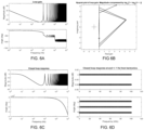
- FIG. 6 A illustrates the loop gain as a function of frequency of an example pure inter-period controller.
- FIG. 6 B illustrates the Nyquist plot of the loop gain for the inter-period controller generating the loop gain of FIG. 6 A .
- FIG. 6 C illustrates the closed loop response as a function of frequency for the inter-period controller generating the loop gain of FIG. 6 A .
- FIG. 6 D illustrates the closed loop response as a function of frequency at and close to the harmonics of the input waveform for the pure inter-period controller.
- FIG. 7 A illustrates the loop gain as a function of frequency of an example combined inter-period and intra-period controller with a 0.1 weighting for the inter-period part and a 0.9 weighting for the intra-period part.
- FIG. 7 B illustrates the Nyquist plot of the loop gain related to FIG. 7 A .
- FIG. 7 C illustrates the closed loop response as a function of frequency of the example combined controller related to FIG. 7 A .
- FIG. 7 D illustrates the closed loop response as a function of frequency at and close to the harmonics of the input waveform for the combined inter-period and intra-period controller related to FIG. 7 A .
- FIG. 8 A illustrates the loop gain as a function of frequency of an example combined inter-period and intra-period controller with a 0.01 weighting for the inter-period part and a 0.99 weighting for the intra-period part.
- FIG. 8 B illustrates the Nyquist plot of the loop gain for the combined controller related to FIG. 8 A .
- FIG. 8 C illustrates the closed loop response as a function of frequency for the combined controller related to FIG. 8 A .
- FIG. 8 D illustrates the closed loop response as a function of frequency at and close to the harmonics of the input waveform for the same combined inter-period and intra-period controller related to FIG. 8 A .
- FIG. 9 illustrates a block diagram of a multi-input multi-output version of a combined inter-period and intra-period controller according to one embodiment of the present disclosure.
- FIG. 10 illustrates an embodiment of a multi-generator power delivery system.
- FIG. 11 illustrates another embodiment of a multi-generator power delivery system.
- FIG. 12 illustrates yet another embodiment of a multi-generator power delivery system.
- Embodiments of the present disclosure provide a plasma power delivery system that produces an output, such as delivered power, voltage, current, and forward power, that follows a prescribed pattern of output versus time where the pattern repeats with a repetition period by controlling sections of the pattern based on measurements taken one or more repetition periods in the past as opposed to within the current period.
- an inter-period controller can reproduce output more accurately utilizing a lower bandwidth measurement and control system.
- the benefits provided by the inter-period controller can be advantageous in various contexts including in the presence of plasma generated mixing and intermodulation products.
- the inter-period controller can be combined with a conventional intra-period controller.
- parameters such as generator output frequency, pulse width, and match impedance
- main output may be adjusted together with the main output based on measurements taken one or more repetition periods in the past where the correlation between the control inputs, such as power control, generator frequency, and match variable element settings, and control outputs, such as delivered power and impedance presented to the generator are determined and used by the control system.
- a generator produces an output that follows a prescribed pattern of output versus time where the pattern repeats with a repetition period by controlling a section of the pattern based on measurements taken for the same section one or more repetition periods in the past; as well as such measurements for other sections in the pattern by perturbing the control input, determining the response to the perturbation, and using the response to the perturbation to compensate for coupling between adjacent or closely located time periods in the waveform.
- aspects of the present disclosure are applicable to switch mode power supplies, and controllers for the same, which may be used in eV source applications such as to provide a bias to a substrate as part of an overall power delivery system, as well as other substrate biasing schemes.
- the controller and control schemes discussed herein may also be used to control variable impedance elements (such as vacuum variable capacitors or switched variable reactance elements) of impedance matching networks.
- aspects of the present disclosure may or may not also be used in the controlling of an RF supply to the impedance matching network as part of the overall power delivery system.
- the controller may reside in any part of the power delivery system (e.g., in the generator or in the matching network) and may or may not receive information from and control other parts of the power delivery system.
- a controller residing in the generator may control both a generator power signal and a match that are part of the power delivery system with information obtained only from the generator, only from the match or from both the generator and the match.
- the controller and control schemes discussed herein may also be used in other systems with or without delivering power in a plasma power delivery environment.
- a sensor that the controller bases its decisions on, as well as the controller can both be arranged in the generator.
- FIG. 1 A illustrates a simple analog intra-period
- FIG. 1 B illustrates a simple digital intra-period control systems that may be used to control a plasma power delivery system.
- the difference between an input 101 and output 106 produces an error signal 102 that a controller 103 uses to produce a control input 104 to a plant 105 .
- the controller is a simple integrator with a gain of k.
- the control input 104 , c may be a drive level to a power amplifier, and the plant 105 , P, a power amplifier.
- the loop gain has unity gain at k rad/s or k/(2 ⁇ ) Hz
- the time constant of the system step response is 1/k s
- the integral of the impulse response of the system reaches 63.2% (1 ⁇ 1/e) in 1/k s.
- an input 151 is sampled at a sampling rate of 1/T s and digitized by a sampler 157 .
- the output 156 is sampled and digitized by a sampler 159 and the difference between the input and output produces an error signal 152 that a controller 153 uses to produce a control input 154 which is converted to an analog control signal by a digital to analog converter 158 which is fed to a plant 155 .
- the plant 105 , P is a unity gain block. The same statements regarding relationship between k and the unity gain frequency and response times hold as for the analog controller of FIG. 1 A provided that k is much less than 2 ⁇ /T s .
- FIG. 2 A shows the response 200 of the simple intra-period controller such as shown in FIG. 1 A or FIG. 1 B to a periodic input with period T p , 205 .
- a host of different set points e.g., a set point power of 1, followed by 2, followed by 5, with a ramp to 3 defines one period of the input.
- the output, 202 follows the input, 201 with visible inaccuracy (where the output does not match the input set point).
- the time constant of the closed loop response for this illustration is 10 ⁇ s.
- the output at a given point, A, 203 can be obtained by multiplying the time shifted time reversed impulse response of the system with the input and integrating.
- the normalized time shifted time reversed impulse response of the unit, 204 shows that the output at point A, 203 , is heavily influenced by the very recent past (within one time constant or 10 ⁇ s prior to point A), and almost not at all by events occurring earlier than 10 time constants prior to point A.
- the conventional controller must be very fast. As shown in FIG. 2 B (prior art), speeding up the controller improves the ability of the output to follow the input accurately.
- the time constant of the closed loop response for this illustration is 5 ⁇ s.
- the response, 250 shows that the output, 252 , follows the input, 251 , more closely.
- the normalized time shifted time reversed impulse response 254 shows that the point A, 253 , is now even more heavily influenced by the input in the very recent past.
- the error control is based on the measured value of the current output (within the period) against the set point. So, referring to FIG. 2 A , for example, the measured value of the output at time 1.5 ms would be compared against the set point value at that same time to generate the error signal. Stated differently, the set point values are compared against the measured values during the current period to generate the error signal for the conventional intra-period controller.
- an inter-period controller compares the measured value of the output one or more cycles in the past for a given set point and uses the past measured value at the set point to generate the current error signal and controller output. Referring again to FIG.
- the measured value at time 0.94 ms (which is one waveform repetition period of 0.56 ms earlier or that part of the preceding pulse that correlates with time 1.5 ms) with the same set point of 3 would be used by the controller to generate the error and output, as opposed to the measured value within the pulse at time 1.5 ms.
- the inter-period controller need not be nearly as fast because it relies on a measured value one cycle in the past as opposed to an immediately proximate value within the pulse.
- the pulse (e.g., the pulse over period Tp) is divided into multiple time periods, and the corresponding (same) output value in the same time period of the previous pulse is used for the error signal.
- the time period would encompass the specific value of 0.56 ms within some range.
- the time periods by which pulses are divided are such that any given time period does not encompass different set points, with the exception of sloped set point transitions.
- the inter-period pulse information is stored in some form of memory such that it can be accessed and used by the controller for the error feedback of the succeeding pulse.
- Complicated pulses such as with sloped set point transitions, and otherwise different set points may benefit from relatively smaller time period subdivisions of the pulse, and therefore may require relatively larger and faster memory.
- pulses with between a 100 ms and 10 ⁇ s period T p may be subdivided into 1024 time slices, and output values for each slice stored for comparison to the measured value in the same time slice of the subsequent pulse.
- no error signal is generated.
- information about an impedance presented to a generator one or multiple periods, T p , 205 , in the past can be used to adjust variable impedance elements within the matching network at the present time. The information can be used to calculate adjustments to the variable impedance matching elements without first generating an error signal.
- the setpoint e.g. 101 , 151 , 303 , 351 , 501
- the setpoint is generally constant, but there is a periodic disturbance of the load impedance that must be matched to a desired input impedance.
- Such a periodic disturbance can for example arise from delivering power to a plasma load that follows a prescribed pattern of output versus time where the pattern repeats with a repetition period.
- a synchronization signal from for example the power source providing the prescribed pattern of power can be provided to the matching network to assist the matching network in synchronizing with the repetitive waveform of the disturbance.
- simultaneous control of the generator power signal and variable impedance elements within the matching network can be adjusted via an inter-period control scheme and a single controller, optionally arranged at the generator. This scheme may be based on measurements from a sensor arranged at the generator, at the match network, or therebetween, and the controller may optionally be arranged in the generator.
- FIG. 3 A illustrates a block diagram of one example of an inter-period controller 300 that may be implemented in a plasma power delivery system according to one embodiment of the present disclosure.
- FIG. 3 B illustrates a block diagram of an alternate example implementation of an inter-period controller 350 that may be implemented in a plasma power delivery system according to another embodiment of the present disclosure.
- Some implementations of the inter-period controllers described herein may be considered multi-input-multi-output (MIMO) controllers.
- MIMO multi-input-multi-output
- the controllers or more generally control elements may be implemented in hardware and software, with various possible combinations of the same.
- the control element may be integrated with the generator or other device, or may be a separate component.
- the inter-period controller may reside in a different piece of equipment from what is being controlled.
- a controller connected to an impedance matching network may reside in the generator but control the generator power signal and the variable impedance elements in the impedance matching network.
- forward and reflected signals from a sensor such as a coupler may be obtained from a coupler residing in the generator, filtered in analog, digitized in an analog to digital converter, and processed to extract the impedance presented to the generator by the match by a microprocessor running a software program or by digital logic circuits implemented in, for example, an FPGA.
- the measurements can be stored in memory by a microprocessor or reconfigurable digital circuits residing in an FPGA.
- the memory containing samples of impedance measurements at different times can be processed using software running in a microprocessor or by an FPGA.
- the software or FPGA can use samples one or multiple waveform repetition periods in the past to implement an inter-period control scheme.
- information about past values of variable impedance elements in the match can also be used.
- the controller can then send control signals to the match to change variable impedance elements in the match and optionally simultaneously control the generator.
- the inter-period controller may also work with the sensor, for instance, by providing information about a start of a pulse or a start of a rapid power swing in the generator to the sensor, before such an event takes place. In this way, the sensor can predictively know when to begin sampling, and thus operate more quickly than prior art sensors that might have started sampling only after a pulse is identified or a rapid swing in power is first identified.
- the controller can control the generator frequency and provide this frequency preemptively to the sensor allowing more rapid assessment of impedance seen by the generator than traditional sensors since those sensors often first measure frequency before measuring impedance.
- FIG. 3 A implements the inter-period controller (providing an interleaved scheme) as a number, N, of controllers each running at the repetition period, T p , of the input.
- the block 301 shows the first such controller and the block 302 shows the N-th such controller.
- the input, 303 is sampled and digitized by an analog to digital converter, 304 , at a sampling rate of 1/T s . (The input may already exist as a data stream in which case the converter 304 is not used.)
- the sampled input is switched or routed to the controllers in turn by a switch, 305 so that each controller receives an updated input at a rate of 1/T p .
- the outputs of the controllers are routed to a common control input, c, by a switch 306 .
- the control input is converted to analog by a digital to analog converter 307 and applied to the control input of a plant, P, 308 .
- the output, y, 309 is sampled by each controller at a rate of 1/T p by a sampler ( 313 for controller 301 ).
- Each controller creates an error function ( 310 for controller 301 ) by subtracting the input from the sampled output. (Since the sampled output is delayed by a waveform period, T p , this implements an inter-period controller.)
- the error function is integrated (by 311 for controller 301 ) producing an output ( 312 for controller 301 ).
- extra controllers may be utilized. For example, there may be N+3 controllers to deal with a T p that can vary three sampling periods.
- FIG. 3 B shows an alternate implementation of an inter-period controller 350 in accordance with an embodiment of the present disclosure.
- the input 351 is sampled and digitized by an analog to digital converter, 352 , at a sampling rate of 1/T s .
- the input may already exist as a data stream in which case the converter 352 is not used.
- the output 358 is sampled and digitized by an analog to digital converter 359 .
- the output may be a digital data stream derived from a measurement of the output in which case the analog to digital converter may not be implemented as shown.
- An error function 353 is obtained by subtracting the input from the output.
- the controller 354 generates the control input to the plant, c, 355 , from the values of the control input to the plant, c, 355 , and the error function, e, 353 , one period of the input, T p ago. This is significantly different from a conventional intra-period controller as will be shown infra.
- the control input to the plant is converted to an analog signal by a digital to analog converter, 356 , and applied to a plant, 357 .
- provision can be made to deal with situations where the repetition period of the input, T p may vary a few sampling periods. In this case, N is allowed to vary based on the number of sampling periods T s that fit in the previous period of the input T p .
- the herein-disclosed inter-period controller for instance, sending a synchronization signal from the power source to the matching network, or an inter-period controller that simultaneously tunes the generator and the match network, has a number of advantages over the prior art.
- novel power delivery methods are enabled, such as the ability to simultaneously tune a match network and a generator (e.g., via control signal 306 , 355 , 506 , or the input to 905 ) or tune the match network while pulsing or changing the waveform of the generator output (e.g., via control signal 306 , 355 , 506 , or the input to 905 ).
- the herein-disclosed plants can be a generator, a match network, or both a generator and match network (where the control signal is actually two distinct signals—one for each of the generator and the match network).
- this system and approach enables rapidly-adjustable, accurate, and consistent power delivery to a plasma load.
- the speed of a power delivery system using the herein-disclosed inter-period controller is particularly useful in dynamic power applications (e.g., pulsed generator output).
- the inter-period controller can provide the sensor with operating parameters of the generator (e.g., any of the plants disclosed herein), such as frequency, so that the sensor need not measure frequency before beginning to sample for impedance. Earlier sampling means that impedance can be determined faster than in the art.
- the inter-period controller can also provide the sensor with an indication of the start of pulsing or a change in a power waveform, thus preventing the sensor from having to detect such a change before sampling begins. This also enables the sensor to begin measuring impedance sooner than sensors in the art.
- the inter-period controller also improves the accuracy of power delivery in four ways. First, when multiple sensors are used to measure power and impedance each sensor has an error function associated with that sensor resulting from calibrations that are made to each sensor. By using a single sensor to measure power and impedance, only a single calibration is performed, and therefore less error is introduced.
- sampling typically begins after a pulse or change in the generator waveform has been detected, whereas here, the inter-period controller indicates to the sensor a start of a pulse or change in the generator waveform before or when the pulse or waveform change occurs. As such, the sensor can begin sampling earlier than is possible in the art, thus enabling more accurate impedance measurements.
- a measure of impedance depends on the frequency of the signal being measured, and thus errors in measuring frequency translate to errors in the impedance that is measured.
- Prior art impedance measurements are often made after a sensor in the match network measures frequency, thus introducing unnecessary error.
- error is introduced by analog variation in the broadband sensor as a function of frequency.
- the inter-period controller can take component variations into account by identification of the components to the inter-period controller.
- the generator, match network, and sensor can identify themselves to the inter-period controller via brand, model, serial number or other identifying information. Also, they can provide operating characteristics such as status, set point, and configuration, to name a few. Authentication may take place via an authentication algorithm. As such, in one embodiment, only specific types or brands of generator and match network are operable when connected via a transmission medium.
- the inter-period controller can also query the generator, the match network, and the sensor to determine their unit type, serial number, part number, or any other identifying information. With this knowledge, the inter-period controller can tailor instructions to the generator and the match network to account for variations in components, thus allowing the inter-period controller to effect more accurate and consistent power delivery than is possible in the art.
- the inter-period controller also improves the consistency (or quality) of power delivery because of the ability to measure both power and impedance. In part, consistency is improved via the greater accuracy described above (e.g., decreased error stack-up and earlier and more extensive sampling). Consistency is also improved, because, where the prior art had difficulty maintaining stability in multiple control loops of a power delivery system, the single inter-period controller can control the multiple control loops and ensure stability and synchronization between the control loops.
- the inter-period controller benefits from use with a single sensor to monitor both power output of the generator and an impedance seen by the generator.
- the sensor can measure voltage, current, phase, impedance, and power at an output of the generator.
- the sensor can be arranged at an output of the generator.
- the sensor can measure impedance seen by the generator in addition to power from the generator because of the ability to remotely measure impedance. Remote impedance measurements look at impedance at a location physically remote from the sensor. This is made possible by (1) the sensor having a more linear response with respect to increasing voltage standing wave ratio referenced to a calibration impedance than sensors in the art, and (2) the sensor can more closely measure a phase of the generator output power.
- sensors can be calibrated to operate optimally close to a center operating impedance (e.g., 50 ⁇ ), but due to their nonlinear response to impedance variations, as impedance moves away from the calibration impedance, sensor accuracy degrades rapidly. This inaccuracy for physically local measurements is amplified when making measurements over large physical distances.
- the herein-disclosed sensor has a more linear response on the voltage standing wave ratio circle, which enables accurate impedance measurements at impedances far from the impedance calibration point and therefore at physically remote locations.
- the senor can more closely measure a phase of the generator output than could prior generations of sensors.
- phase angle measurement accuracy there is extreme sensitivity to phase angle measurement accuracy, and thus in the resulting impedance and power measurements. Since the sensor can more accurately measure phase angle, it is better able to remotely measure impedance.
- the senor is a directional coupler.
- a directional coupler can measure the scaled power of forward and reverse power as well as the phase difference between them. The directional coupler can then pass the scaled power and phase difference back to the inter-period controller.
- Scaled power is a voltage that the directional coupler provides to a measurement system that is proportional to an output voltage of the generator operating into its nominal load condition (e.g., 50 ⁇ ).
- the inter-period controller manages operation of both the generator and the match network, simultaneous tuning of those components is possible.
- the inter-period controller can instruct the generator to adjust an amplitude, carrier frequency, power frequency, pulse width, pulse duty cycle, or waveform of the generator power output.
- the inter-period controller can also instruct the match network to adjust an impedance of the match network, for instance by having a motor drive board adjust variable capacitors of the match network.
- the inter-period controller can pass instructions to the match network to adjust impedance.
- the inter-period controller can (1) pass instructions to the match network to alter the impedance that the generator sees, (2) pass instructions to the generator to alter the power output frequency, or (3) pass instructions to the match network to alter the impedance that the generator sees and pass instructions to the generator to alter its power output frequency. Since the generator frequency is more quickly adjusted than the impedance of the match network, instructing the generator to tune via frequency in addition to or instead of the match network adjusting impedance, can be preferable where fast tuning is required. In other words, impedance matching can be performed via the inter-period controller's simultaneous tuning of the generator and the match network.
- the inter-period controller can also take into account non-electrical characteristics of the plasma load when managing operations of the generator and the match network. For instance, the inter-period controller can consider chamber pressure, gas chemistry in the chamber, ion energy of the plasma, light intensity of the plasma, spectral content of light emitted by the plasma, and plasma arcing to name a few non-limiting examples.
- an optional second sensor can monitor non-electrical characteristics of the plasma load or the plasma processing chamber (not illustrated), such as chamber pressure, gas chemistry in the chamber, ion energy of the plasma, light intensity of the plasma, spectral content of light emitted by the plasma, and plasma arcing, to name a few non-limiting examples.
- FIGS. 4 A- 4 D show the response of an inter-period controller that may be implemented in a plasma power delivery system according to one embodiment of the present disclosure to a periodic control input.
- FIGS. 4 A and 4 B the response 400 of the output 402 to a periodic input 401 is shown.
- the output slowly converges to the input ( FIG. 4 A ), but after about 30 cycles of the input ( FIG. 4 B ) the output 404 follows the input 403 with almost imperceptible error.
- FIG. 4 C shows that a point A, 451 , on the response 450 and the points that influence point A. Note that for the inter-period controller point A, 451 , is still significantly influenced by the input 5 ms in the past.
- FIG. 5 illustrates a block diagram of an example combined inter-period and intra-period controller 500 that may be implemented in a plasma power delivery system according to one embodiment of the present disclosure.
- the input, 501 is sampled and digitized by an analog to digital converter, 502 , at a sampling rate of 1/T s .
- the input may already exist as a data stream in which case the converter 502 is not used.
- the output 509 is sampled and digitized by an analog to digital converter 510 .
- the output may be a digital data stream derived from a measurement of the output in which case the analog to digital converter may not be implemented as shown.
- An error function 503 is obtained by subtracting the input from the output.
- the control input, c, 506 is a weighted average of a value based on values one sampling period, T s , ago and one period of the input, T p , ago. This weighting is perhaps more clearly illustrated in the sequence (sampled time) domain shown in equation 505 .
- the control input to the plant, c, 506 is converted to an analog signal by a digital to analog converter, 507 , and applied to a plant, 508 . Provision can be made to deal with situations where the repetition period of the input, T p , may vary a few sampling periods. In this case, N is allowed to vary based on the number of sampling periods, T s , that fit in the previous period of the input, T p .
- the Bode plot of the loop gain of an inter-period controller is shown in FIG. 6 A .
- the loop gain is very different from a traditional intra-period controller.
- FIG. 6 B shows a Nyquist plot of the loop gain.
- the magnitude of the loop gain is scaled by log 2 (1+log 2 (1+•)). This mapping maps 0 to 0, 1 to 1 and is monotonically increasing so we can still verify that the point ⁇ 1+j0 in the complex plane is not encircled.
- FIG. 6 C shows the magnitude and phase of the closed loop response of the system.
- FIG. 6 D shows the magnitude and phase of the closed loop response of the system only at the harmonics of the input and +/ ⁇ 1 Hz from the harmonics of the input.
- FIG. 6 D shows that the gain at the harmonics is unity gain confirming that a periodic input with period T p will be followed with precision.
- the points that have exactly 0 dB gain and 0 phase (unity gain) are exactly at the harmonics of the input, points having a gain of ⁇ 0.04 dB and phase of +/ ⁇ 5 degrees are 1 Hz above and below the harmonic of the input.
- the Bode plot of the loop gain of the combined inter-period and intra-period controller is shown in FIG. 7 A .
- the loop gain is very different from a traditional intra-period controller.
- the magnitude of the gain returns to high but finite values at the harmonics of the input (multiples of 1/T p ); a unique property of the combined inter-period and intra-period controller.
- FIG. 7 B shows a Nyquist plot of the loop gain. To facilitate interpretation of the Nyquist plot, the magnitude of the loop gain is scaled by log 2 (1+log 2 (1+•)).
- FIG. 7 C shows the magnitude and phase of the closed loop response of the system.
- FIG. 7 D shows the magnitude and phase of the closed loop response of the system only at the harmonics of the input and +/ ⁇ 1 Hz from the harmonics of the input.
- FIG. 7 D shows that the gain at the first few harmonics of the input is close to unity gain showing that the first few harmonic components of the input will be followed with good precision.
- the Bode plot of the loop gain of the combined inter-period and intra-period controller is shown in FIG. 8 A .
- the loop gain approaches that of a traditional intra-period controller.
- FIG. 8 B shows a Nyquist plot of the loop gain.
- the magnitude of the loop gain is scaled by log 2 (1+log 2 (1+)). This mapping maps 0 to 0, 1 to 1 and is monotonic increasing so we can still verify that the point ⁇ 1+j0 in the complex plane is not encircled.
- the Nyquist plot shows that the system is stable.
- FIG. 8 C shows the magnitude and phase of the closed loop response of the system.
- FIG. 7 D shows the magnitude and phase of the closed loop response of the system only at the harmonics of the input and +/ ⁇ 1 Hz from the harmonics of the input.
- FIG. 7 D shows that the gain at the first few harmonics of the input is close to unity gain showing that the first few harmonic components of the input will be followed with good precision.
- This controller approaches the performance of an intra-period controller with a gain cross over frequency of 10 kHz.
- FIG. 9 illustrates a block diagram of a multi-input multi-output version of an example combined inter-period and intra-period controller 900 that may be implemented in a plasma power delivery system according to one embodiment of the present disclosure.
- the input, 901 is sampled and digitized by analog to digital converters, 902 , at a sampling rate of 1/T s .
- the input may already exist as a data stream in which case the converters 902 are not used.
- the input is multi-dimensional and may, for example, contain inputs for output power and generator source impedance.
- the output 907 is sampled and digitized by analog to digital converters 909 .
- the output may be a digital data stream derived from a measurement of the output in which case the analog to digital converters may not be implemented as shown).
- the output is multi-dimensional and may, for example, include measurements of output power and impedance presented to the generator.
- the dimensionality of the input 901 and output 907 do not have to agree. This is so because an element of the output may contain a measure of something that is being minimized or maximized and thus does not require an input (e.g., the mismatch of the load impedance presented to the generator to a desired load impedance). Also, an element of the input may not require a corresponding measurement if the value can simply be set and does not require a corresponding measurement (e.g., setting the generator source impedance).
- Measurements of the input 901 , control input 904 , perturbation 908 , and output 907 are stored in a memory 910 .
- the plant 906 can include the generator and the match network (i.e., the summation may produce two distinct control signals that are both passed through the digital to analog converters 905 ).
- the controller can also generate a perturbation 908 that is added to the calculated control.
- the control input 904 to the plant added to the perturbation 908 is converted to an analog signals by digital to analog converters, 905 , and applied to a plant, 906 .
- Perturbations 908 can be used to extract correlations between the control input 904 and output 907 . For example perturbing the control element in 904 that primarily controls output power (e.g. drive level to the generator) and observing the change in both output power and impedance presented to the generator by the plasma load (or match network) and then perturbing the control element that primarily controls the impedance presented to the generator (e.g.
- control inputs 904 and outputs 907 are also modulated (assuming the load is nonlinear as is the case for most plasma loads).
- correlation can be extracted between different time periods.
- the controller can determine how a change in an element of the control input in one time period affects the output in successive time periods.
- Output resistance is only one component of load impedance.
- load impedance that is important, not just the resistive part of load impedance.
- a third input would be utilized (e.g., a variable reactance element in a matching network), or optimization techniques could be employed to find the best solution using only two inputs controlling three outputs rather than the simple computations in the example.
- Multi-input multi-output control in conjunction with inter-period control allows control of multiple parameters in one control loop. This avoids the problem of interfering control loops which normally necessitates using widely differing speeds for different control loops in the same plasma power delivery system.
- Inter-period control allows for a single controller to more readily control multiple generators delivering power to the same plasma system.
- the data rate for inter-period and intra-period controllers are the same since the control input to the plant is updated at the sampling rate 1/T s .
- the intra-period controller needs information from one sampling period T s earlier to update a current control input to a plant whereas the inter-period controller needs information from one input period T p earlier to update a control input to a plant. Since in most cases T p is multiple times longer than T s , it is much easier to get information to and from a controller before that information is needed for the inter-period controller.
- Inter-period controllers can thus much more readily take interactions between different generators into account to improve overall control of all generators delivering power to the same plasma system.
- FIG. 10 illustrates an embodiment of a multi-generator power delivery system 1000 .
- the power delivery system 1000 includes three generators 1002 a , 1002 b , 1002 c , such as the plant 906 in FIG. 9 , each with a match network 1004 a , 1004 b , 1004 c used to minimize reflected power as the generators 1002 a , 1002 b , 1002 c provide power to a plasma load 1006 .
- a sensor 1014 a , 1014 b , 1014 c is included for monitoring generator 1002 a , 1002 b , 1002 c voltage, current, phase, impedance, and power.
- the sensors 1014 a , 1014 b , 1014 c can be part of each generator 1002 a , 1002 b , 1002 c or coupled to each generator 1002 a , 1002 b , 1002 c or external to each generator 1002 a , 1002 b , 1002 c .
- the sensors 1014 a , 1014 b , 1014 c relay voltage, current, phase, power and impedance measurements to an inter-period controller 1012 .
- the sensors 1014 a , 1014 b , 1014 c can also relay identifications of themselves including information such as brand, make model, configuration and operating parameters to the inter-period controller 1012 .
- the generators 1002 a , 1002 b , 1002 c and the match networks 1004 a , 1004 b , 1004 c can also identify themselves to the inter-period controller 1012 , for instance via the RF engines 1013 a , 1013 b , 1013 c and the impedance control systems 1015 a , 1015 b , 1015 c , respectively.
- the inter-period controller 1012 can manage communications between the generators 1002 a , 1002 b , 1002 c , the match networks 1004 a , 1004 b , 1004 c , and the sensors 1014 a , 1014 b , 1014 c .
- the inter-period controller 1012 is also configured to pass instructions to the generators 1002 a , 1002 b , 1002 c and the match networks 1004 a , 1004 b , 1004 c regarding how and when to adjust internal parameters.
- the inter-period controller 1012 enables the generators 1002 a , 1002 b , 1002 c and the match networks 1004 a , 1004 b , 1004 c to operate in unison and in a fashion that takes into account variations between components as well as operation of other components. In some instances, this unified operation of the power delivery system 1000 can also consider non-electrical factors such as plasma chamber gas chemistry or processing end point. In an embodiment, a frequency of the generators 1002 a , 1002 b , 1002 c can be tuned while also tuning the match networks 1004 a , 1004 b , 1004 c.
- a particular challenge in the art is generating consistent power since each generator 1002 a , 1002 b , 1002 c sees the other generators 1002 a , 1002 b , 1002 c through the transmission mediums 1010 a , 1010 b , 1010 c or the plasma load 1006 (depending on the configuration).
- traditional multi-generator systems are plagued by cross talk interaction between the generators 1002 a , 1002 b , 1002 c .
- the generators 1002 a , 1002 b , 1002 c and match networks 1004 a , 1004 b , 1004 c can communicate with each other via the inter-period controller 1012 and to be controlled with the inter-period controller 1012 taking into account the operation of all of these components simultaneously, consistent and accurate power can be provided to the plasma load 1006 .
- a user can interface with an external controller 1020 , which is in communication with the inter-period controller 1012 .
- the external controller 1020 can send and receive both instructions and data to and from the inter-period controller 1112 .
- User control of the generators 1002 a , 1002 b , 1002 c and match networks 1004 a , 1004 b , 1004 c is made via the inter-period controller 1012 by way of the external controller 1020 .
- inter-period controller 1012 is illustrated as being part of generator 1002 a , it can also be a part of generator 1002 b or generator 1002 c . Alternatively, all other locations within the power delivery system 1000 can also be used.
- the inter-period controller 1012 can communicate with an RF engine 1013 a , 1013 b , 1013 c of each generator 1002 a , 1002 b , 1002 c and an impedance control system 1015 a , 1015 b , 1015 c of each match network 1004 a , 1004 b , 1004 c .
- the inter-period controller 1012 can communicate with and pass instructions to these subcomponents.
- the inter-period controller 1012 can instruct the generators 1002 a , 1002 b , 1002 c and match networks 1004 a , 1004 b , 1004 c to alter operating parameters such as pulse frequency, power, and variable capacitor position, to name three non-limiting examples.
- the inter-period controller 1012 can be implemented according to any one of the embodiments described relative to FIGS. 3 A, 3 B, 5 , and 9 .
- the inter-period controller 1012 can compare measured values of the output of the generators 1002 a , 1002 b , 1002 c one or more cycles in the past for a given set point and use the past measured values at the set point to generate a current error signal and consequently a control signal(s) for the RF engines 1013 a , 1013 b , 1013 c and/or the impedance control systems 1015 a , 1015 b , 1015 c .
- the controller can be considered a multi-input-multi-output (MIMO) controller.
- the input to the inter-period controller 1012 e.g., a power delivery setpoint and pulse frequency setpoint
- the output can be sampled and digitized by analog and digital converters (the output may be a digital data stream derived from a measurement of the output in which case the analog to digital converters may not be implemented).
- the output can be multi-dimensional and may, for example, include measurements of output power from the generators 1002 a , 1002 b , 1002 c and impedance presented to the generators 1002 a , 1002 b , 1002 c .
- the dimensionality of the input and output do not have to agree.
- correlation can be extracted between different time periods.
- the inter-period controller 1012 can determine how a change in an element of the control input in one time period affects the output in successive time periods.
- the inter-period controller 1012 can also be used to impedance match (or tune the generators 1002 a , 1002 b , 1002 c and simultaneously impedance match) using information about an impedance presented to the generators 1002 a , 1002 b , 1002 c and/or values of variable impedance elements in the match networks 1004 a , 1004 b , 1004 c one or multiple periods in the past. These prior impedance measurements can be used to adjust variable impedance elements within the match networks 1004 a , 1004 b , 1004 c at the present time. The information can be used to calculate adjustments to the variable impedance matching elements without first generating an error signal.
- the inter-period controller 1012 can obtain an error function by subtracting the inputs to the generators 1002 a , 1002 b , 1002 c from the generator outputs, as measured by the sensors 1014 a , 1014 b , 1014 c . And this error function can be used to generate the control to the RF engines 1013 a , 1013 b , 1013 c.
- FIG. 11 illustrates another embodiment of a multi-generator power delivery system 1100 .
- FIG. 11 differs from FIG. 10 in that the sensors 1114 a , 1114 b , 1114 c are arranged at outputs of the match network 1104 a , 1104 b , 1104 c instead of at outputs of the generators 1102 a , 1102 b , 1102 c .
- the sensors 1114 a , 1114 b , 1114 c are configured to characterize the power for each generator 1102 a , 1102 b , 1102 c and match network 1104 a , 1104 b , 1104 c by measuring voltage, current, phase, impedance, and/or power at the output of the match networks 1104 a , 1104 b , 1104 c or en route to the plasma load 1106 .
- the sensors 1114 a , 1114 b , 1114 c and the generators 1102 a , 1102 b , 1102 c can identify themselves to the inter-period controller 1112 via the RF engines and the impedance control systems 1115 a , 1115 b , 1115 c , respectively.
- the power delivery system 1100 can interface with users via an external controller 1120 .
- the external controller 1120 can be in communication with the inter-period controller 1112 and send and receive both instructions and data to and from the inter-period controller 1112 .
- the inter-period controller 1112 can be arranged as part of the generator 1102 a , as illustrated, or as part of any of the other components within the power delivery system 1100 or adjacent to any of these components, but still within the power delivery system 1100 .
- impedance control systems 1115 a , 1115 b , 1115 c are illustrated for each match network 1104 a , 1104 b , 1104 c , one of skill in the art will recognize that these can either represent separate hardware (or software or firmware) components, or a single hardware component comprising a separate logical block for each match network 1104 a , 1104 b , 1104 c .
- a single impedance control system may control operating parameters of all three match networks 1104 a , 1104 b , 1104 c.
- the sensors 1114 a , 1114 b , 1114 c can be replaced by a single sensor located between the match networks 1104 a , 1104 b , 1104 c and the plasma load 1106 .
- the single sensor can measure voltage, current, phase, impedance, and power just as the three sensors 1114 a , 1114 b , 1114 c illustrated are configured to.
- each component may have a separate signal path to the inter-period controller 1112 .
- the generators 1102 a , 1102 b , 1102 c may have one signal path to the inter-period controller 1112 while the match networks 1104 a , 1104 b , 1104 c have another signal path to the inter-period controller 1112 .
- the sensors 1114 a , 1114 b , 1114 c can also have their own signal path to the inter-period controller 1112 .
- the inter-period controller 1112 can be implemented according to any one of the embodiments described relative to FIGS. 3 A, 3 B, 5 , and 9 .
- the inter-period controller 1112 can compare measured values of the output of the match networks 1104 a , 1104 b , 1104 c one or more cycles in the past for a given set point and use the past measured values at the set point to generate a current error signal and consequently a control signal for the RF engines 1113 a , 1113 b , 1113 c and/or the impedance control systems 1115 a , 1115 b , 1115 c .
- the controller can be considered a multi-input-multi-output (MIMO) controller.
- the input to the inter-period controller 1112 e.g., a power delivery setpoint and pulse frequency setpoint
- the input to the inter-period controller 1112 can be a multi-dimensional array and may, for example, contain inputs for output power and generator source impedance.
- the output can be sampled and digitized by analog and digital converters (the output may be a digital data stream derived from a measurement of the output in which case the analog to digital converters may not be implemented).
- the output can be multi-dimensional and may, for example, include measurements of output power from the matches 1104 a , 1104 b , 1104 c and match impedance.
- correlation can be extracted between different time periods.
- the inter-period controller 1112 can determine how a change in an element of the control input in one time period affects the output in successive time periods.
- the inter-period controller 1112 can also be used to impedance match (or tune the generators 1102 a , 1102 b , 1102 c and simultaneously impedance match) using information about an impedance presented to the generators 1102 a , 1102 b , 1102 c and/or values of variable impedance elements in the match networks 1104 a , 1104 b , 1104 c one or multiple periods in the past. These prior impedance measurements can be used to adjust variable impedance elements within the match networks 1104 a , 1104 b , 1104 c at the present time. The information can be used to calculate adjustments to the variable impedance matching elements without first generating an error signal.
- the inter-period controller 1112 can obtain an error function by subtracting the inputs to the generators 1102 a , 1102 b , 1102 c from the match outputs, as measured by the sensors 1114 a , 1114 b , 1114 c at the match outputs. And this error function can be used to generate the control to the RF engines 1113 a , 1113 b , 1113 c.
- FIG. 12 illustrates yet another embodiment of a multi-generator power delivery system 1200 .
- FIG. 12 differs from FIGS. 10 and 11 in that the sensors of those figures are replaced here by a single sensor 1214 arranged at an input of the plasma load 1206 .
- the sensor 1214 is configured to characterize the power for each generator 1202 a , 1202 b , 1202 c and match network 1204 a , 1204 b , 1204 c.
- the power delivery system 1200 can interface with users via an external controller 1220 .
- the external controller 1220 can be in communication with the inter-period controller 1212 and send and receive both instructions and data to and from the inter-period controller 1212 .
- each component may have a separate signal path to the inter-period controller 1212 .
- the generators 1202 a , 1202 b , 1202 c may have one signal path to the inter-period controller 1212 while the match networks 1204 a , 1204 b , 1204 c have another signal path to the inter-period controller 1212 .
- the sensors 1214 a , 1214 b , 1214 c can also have their own signal path to the inter-period controller 1212 .
- the inter-period controller 1212 can be implemented according to any one of the embodiments described relative to FIGS. 3 A, 3 B, 5 , and 9 .
- the inter-period controller 1212 can compare measured values of the output of the match networks 1204 a , 1204 b , 1204 c one or more cycles in the past for a given set point and use the past measured values at the set point to generate a current error signal and consequently a control signal for the RF engines 1213 a , 1213 b , 1213 c and/or the impedance control systems 1215 a , 1215 b , 1215 c .
- the controller can be considered a multi-input-multi-output (MIMO) controller.
- the input to the inter-period controller 1212 e.g., a power delivery setpoint and pulse frequency setpoint
- the output can be sampled and digitized by analog and digital converters (the output may be a digital data stream derived from a measurement of the output in which case the analog to digital converters may not be implemented).
- the output can be multi-dimensional and may, for example, include measurements of summed output power from the match networks 1204 a , 1204 b , 1204 c and plasma load 1206 impedance. The dimensionality of the input and output do not have to agree.
- correlation can be extracted between different time periods. For example, the inter-period controller 1212 can determine how a change in an element of the control input in one time period affects the output in successive time periods.
- the inter-period controller 1212 can also be used to impedance match (or tune the generators 1202 a , 1202 b , 1202 c and simultaneously impedance match) using information about an impedance presented to the generators 1202 a , 1202 b , 1202 c and/or values of variable impedance elements in the match networks 1204 a , 1204 b , 1204 c one or multiple periods in the past. These prior impedance measurements can be used to adjust variable impedance elements within the match networks 1204 a , 1204 b , 1204 c at the present time. The information can be used to calculate adjustments to the variable impedance matching elements without first generating an error signal.
- the inter-period controller 1212 can obtain an error function by subtracting the inputs to the generators 1202 a , 1202 b , 1202 c from the match outputs, as measured by the sensor 1214 at the plasma load 1206 (e.g., at the processing chamber). And this error function can be used to generate the control to the RF engines 1213 a , 1213 b , 1213 c.
- each external controller of FIGS. 10 - 12 is illustrated as having its own signal path to the local controller, in alternative embodiments, each external controller can share the same signal path used by the sensor generators, and match networks use to communicate with the local controller.
- FIGS. 10 - 12 show three sets of generators, match networks, and sensors, in other embodiments, these configurations can be implemented with two or more sets of generators, match networks, and sensors.
- the single sensor could measure power output locally for one generator and remotely for two generators.
- the single sensor could also remotely characterize impedance for all three match networks.
- the controllers used samples of signals one sampling period, T s , or one repetition period, T p , in the past.
- the controller can also use samples of signals multiple sampling periods or repetition periods in the past.
- Some advantages of this approach include the ability to provide accurate power regulation over a wide dynamic range, faster power stabilization during transients, and decreased reflected power, for both pulsed and continuous wave (CW) power.
- CW continuous wave
Abstract
Description
Assuming that through perturbation the correlation between the outputs in the 7th time period and the control inputs in the 6th and 7th time periods are estimated:
It follows that (approximately):
When the inputs for the 7th time period need to be adjusted, the changes to the inputs of the 6th time period have already been made, thus:
is known and it follows that:
The simple example uses two inputs to the plant (drive and frequency) and two outputs (output power and load resistance). Output resistance is only one component of load impedance. In a practical application, load impedance that is important, not just the resistive part of load impedance. In such a case a third input would be utilized (e.g., a variable reactance element in a matching network), or optimization techniques could be employed to find the best solution using only two inputs controlling three outputs rather than the simple computations in the example.
Claims (20)
Priority Applications (3)
| Application Number | Priority Date | Filing Date | Title |
|---|---|---|---|
| US17/220,530 US11651939B2 (en) | 2017-07-07 | 2021-04-01 | Inter-period control system for plasma power delivery system and method of operating same |
| PCT/US2022/016291 WO2022211915A1 (en) | 2021-04-01 | 2022-02-14 | Inter-period control system for plasma power delivery system and method of operating the same |
| TW111105679A TW202241217A (en) | 2021-04-01 | 2022-02-16 | Inter-period control system for plasma power delivery system and method of operating the same |
Applications Claiming Priority (4)
| Application Number | Priority Date | Filing Date | Title |
|---|---|---|---|
| US201762529963P | 2017-07-07 | 2017-07-07 | |
| US16/028,131 US10861677B2 (en) | 2017-07-07 | 2018-07-05 | Inter-period control system for plasma power delivery system and method of operating the same |
| US17/113,088 US11450510B2 (en) | 2017-07-07 | 2020-12-06 | Inter-period control system for plasma power delivery system and method of operating same |
| US17/220,530 US11651939B2 (en) | 2017-07-07 | 2021-04-01 | Inter-period control system for plasma power delivery system and method of operating same |
Related Parent Applications (1)
| Application Number | Title | Priority Date | Filing Date |
|---|---|---|---|
| US17/113,088 Continuation-In-Part US11450510B2 (en) | 2017-07-07 | 2020-12-06 | Inter-period control system for plasma power delivery system and method of operating same |
Publications (2)
| Publication Number | Publication Date |
|---|---|
| US20210249228A1 US20210249228A1 (en) | 2021-08-12 |
| US11651939B2 true US11651939B2 (en) | 2023-05-16 |
Family
ID=77178294
Family Applications (1)
| Application Number | Title | Priority Date | Filing Date |
|---|---|---|---|
| US17/220,530 Active 2038-10-17 US11651939B2 (en) | 2017-07-07 | 2021-04-01 | Inter-period control system for plasma power delivery system and method of operating same |
Country Status (1)
| Country | Link |
|---|---|
| US (1) | US11651939B2 (en) |
Families Citing this family (4)
| Publication number | Priority date | Publication date | Assignee | Title |
|---|---|---|---|---|
| US11615943B2 (en) * | 2017-07-07 | 2023-03-28 | Advanced Energy Industries, Inc. | Inter-period control for passive power distribution of multiple electrode inductive plasma source |
| CN115662868A (en) | 2017-07-07 | 2023-01-31 | 先进能源工业公司 | Intercycle control system for plasma power delivery system and method of operating the same |
| US11651939B2 (en) * | 2017-07-07 | 2023-05-16 | Advanced Energy Industries, Inc. | Inter-period control system for plasma power delivery system and method of operating same |
| US11888553B2 (en) * | 2019-10-18 | 2024-01-30 | Nokia Technologies Oy | Massive MIMO antenna array |
Citations (92)
| Publication number | Priority date | Publication date | Assignee | Title |
|---|---|---|---|---|
| JPS61245202A (en) | 1985-04-23 | 1986-10-31 | Isao Takahashi | Non-interference shortest time control method |
| US5325019A (en) * | 1992-08-21 | 1994-06-28 | Sematech, Inc. | Control of plasma process by use of harmonic frequency components of voltage and current |
| JPH06243992A (en) | 1993-02-16 | 1994-09-02 | Tokyo Electron Ltd | Plasma processing device |
| US5517084A (en) | 1994-07-26 | 1996-05-14 | The Regents, University Of California | Selective ion source |
| US5767628A (en) | 1995-12-20 | 1998-06-16 | International Business Machines Corporation | Helicon plasma processing tool utilizing a ferromagnetic induction coil with an internal cooling channel |
| JPH1187097A (en) | 1997-09-10 | 1999-03-30 | Adtec:Kk | Impedance matching and power control system for high frequency plasma processing device |
| US5907221A (en) | 1995-08-16 | 1999-05-25 | Applied Materials, Inc. | Inductively coupled plasma reactor with an inductive coil antenna having independent loops |
| US6180019B1 (en) | 1996-11-27 | 2001-01-30 | Hitachi, Ltd. | Plasma processing apparatus and method |
| US6204607B1 (en) | 1998-05-28 | 2001-03-20 | Applied Komatsu Technology, Inc. | Plasma source with multiple magnetic flux sources each having a ferromagnetic core |
| US6273022B1 (en) | 1998-03-14 | 2001-08-14 | Applied Materials, Inc. | Distributed inductively-coupled plasma source |
| US6288493B1 (en) | 1999-08-26 | 2001-09-11 | Jusung Engineering Co., Ltd. | Antenna device for generating inductively coupled plasma |
| US6320320B1 (en) | 1999-11-15 | 2001-11-20 | Lam Research Corporation | Method and apparatus for producing uniform process rates |
| US6388382B1 (en) | 1999-03-09 | 2002-05-14 | Hitachi, Ltd. | Plasma processing apparatus and method |
| JP2002184598A (en) | 2000-12-12 | 2002-06-28 | Shimadzu Corp | High-frequency power source unit for icp |
| US6463875B1 (en) | 1998-06-30 | 2002-10-15 | Lam Research Corporation | Multiple coil antenna for inductively-coupled plasma generation systems |
| US20020185228A1 (en) | 2001-03-30 | 2002-12-12 | Chen Jian J. | Inductive plasma processor having coil with plural windings and method of controlling plasma density |
| US6507155B1 (en) | 2000-04-06 | 2003-01-14 | Applied Materials Inc. | Inductively coupled plasma source with controllable power deposition |
| US6583572B2 (en) | 2001-03-30 | 2003-06-24 | Lam Research Corporation | Inductive plasma processor including current sensor for plasma excitation coil |
| US6633017B1 (en) * | 1997-10-14 | 2003-10-14 | Advanced Energy Industries, Inc. | System for plasma ignition by fast voltage rise |
| US6646385B2 (en) | 2000-03-31 | 2003-11-11 | Lam Research Corporation | Plasma excitation coil |
| US6685798B1 (en) | 2000-07-06 | 2004-02-03 | Applied Materials, Inc | Plasma reactor having a symmetrical parallel conductor coil antenna |
| WO2004012220A2 (en) | 2002-07-26 | 2004-02-05 | Varian Semiconductor Equipment Associates, Inc. | Methods and apparatus for monitoring plasma parameters in plasma doping systems |
| US6694915B1 (en) | 2000-07-06 | 2004-02-24 | Applied Materials, Inc | Plasma reactor having a symmetrical parallel conductor coil antenna |
| US6700092B2 (en) * | 2001-04-06 | 2004-03-02 | Eni Technology, Inc. | Pulsing intelligent RF modulation controller |
| JP2004085446A (en) | 2002-08-28 | 2004-03-18 | Daihen Corp | Impedance matching device, and method and system for analyzing output terminal characteristic of the same |
| US20040149218A1 (en) | 2000-08-11 | 2004-08-05 | Applied Materials, Inc. | Plasma immersion ion implantation process using a capacitively coupled plasma source having low dissociation and low minimum plasma voltage |
| US6924455B1 (en) | 1997-06-26 | 2005-08-02 | Applied Science & Technology, Inc. | Integrated plasma chamber and inductively-coupled toroidal plasma source |
| JP2005527078A (en) | 2002-05-20 | 2005-09-08 | イーエヌアイ テクノロジー, インコーポレイテッド | Method and apparatus for VHF plasma processing with load mismatch reliability and stability |
| US7019253B2 (en) | 2000-03-01 | 2006-03-28 | Tokyo Electron Limited | Electrically controlled plasma uniformity in a high density plasma source |
| US7115185B1 (en) * | 2003-09-16 | 2006-10-03 | Advanced Energy Industries, Inc. | Pulsed excitation of inductively coupled plasma sources |
| JP2006286254A (en) | 2005-03-31 | 2006-10-19 | Daihen Corp | High-frequency power supply device |
| US20070107844A1 (en) * | 2005-11-17 | 2007-05-17 | Bullock Scott R | Broadband Techniques to Reduce the Effects of Impedance Mismatch in Plasma Chambers |
| US20070139122A1 (en) | 2005-10-31 | 2007-06-21 | Mks Instruments, Inc. | Radio Frequency Power Delivery System |
| JP2007311182A (en) | 2006-05-18 | 2007-11-29 | Tokyo Electron Ltd | Inductively-coupled plasma processing device, and plasma processing method |
| JP2007336148A (en) | 2006-06-14 | 2007-12-27 | Daihen Corp | Electrical property adjusting device |
| JP2008501224A (en) | 2004-05-28 | 2008-01-17 | ラム リサーチ コーポレーション | Plasma processor having electrodes responsive to multiple RF frequencies |
| JP2008157906A (en) | 2006-12-25 | 2008-07-10 | Adtec Plasma Technology Co Ltd | Output impedance detection method and impedance sensor using this method, electric power monitor in load side connected high frequency electric source and control device for high frequency electric source |
| US20080179948A1 (en) * | 2005-10-31 | 2008-07-31 | Mks Instruments, Inc. | Radio frequency power delivery system |
| JP2009514176A (en) | 2005-10-31 | 2009-04-02 | エム ケー エス インストルメンツ インコーポレーテッド | Radio frequency power carrier system |
| US20090237170A1 (en) | 2008-03-23 | 2009-09-24 | Van Zyl Gideon J | Method and apparatus for advanced frequency tuning |
| US20100026186A1 (en) * | 2008-07-31 | 2010-02-04 | Advanced Energy Industries, Inc. | Power supply ignition system and method |
| US7732759B2 (en) | 2008-05-23 | 2010-06-08 | Tokyo Electron Limited | Multi-plasma neutral beam source and method of operating |
| JP2010521041A (en) | 2007-01-25 | 2010-06-17 | エム ケー エス インストルメンツ インコーポレーテッド | Radio frequency power amplifier stabilization network |
| US20100171427A1 (en) * | 2007-07-23 | 2010-07-08 | Huettinger Elektronik Gmbh + Co. Kg | Protecting High-Frequency Amplifers |
| JP2010219026A (en) | 2009-02-05 | 2010-09-30 | Mks Instruments Inc | Radio frequency power control system |
| US20100270141A1 (en) * | 2009-04-27 | 2010-10-28 | Advanced Energy Industries, Inc. | Detecting and Preventing Instabilities in Plasma Processes |
| US20100276273A1 (en) * | 2009-05-01 | 2010-11-04 | Advanced Energy Industries, Inc. | Method and apparatus for controlling ion energy distribution |
| US7872523B2 (en) * | 2008-07-01 | 2011-01-18 | Mks Instruments, Inc. | Radio frequency (RF) envelope pulsing using phase switching of switch-mode power amplifiers |
| US20110248633A1 (en) * | 2007-11-16 | 2011-10-13 | Advanced Energy Industries, Inc. | Methods and apparatus for applying periodic voltage using direct current |
| US8264154B2 (en) | 2008-05-14 | 2012-09-11 | Applied Materials, Inc. | Method and apparatus for pulsed plasma processing using a time resolved tuning scheme for RF power delivery |
| US20120252141A1 (en) | 2011-03-28 | 2012-10-04 | Tokyo Electron Limited | Adaptive Recipe Selector |
| US8319436B2 (en) | 2009-02-02 | 2012-11-27 | Advanced Energy Industries, Inc. | Passive power distribution for multiple electrode inductive plasma source |
| US20130002136A1 (en) | 2011-01-04 | 2013-01-03 | Advanced Energy Industries, Inc. | System level power delivery to a plasma processing load |
| US20130169359A1 (en) | 2011-12-29 | 2013-07-04 | Mks Instruments, Inc. | Power Distortion-Based Servo Control Systems For Frequency Tuning RF Power Sources |
| JP2013176040A (en) | 2012-02-23 | 2013-09-05 | Mks Instruments Inc | Feedback control and coherency of multiple power supplies in radio frequency power delivery system for pulsed mode scheme in thin film processing |
| KR20140000172A (en) | 2012-06-22 | 2014-01-02 | 램 리써치 코포레이션 | Methods and apparatus for controlling plasma in a plasma processing system |
| US8736377B2 (en) * | 2012-10-30 | 2014-05-27 | Mks Instruments, Inc. | RF pulse edge shaping |
| US20140239813A1 (en) | 2013-02-27 | 2014-08-28 | Advanced Energy Industries, Inc. | Reliable plasma ignition and reignition |
| US8847561B2 (en) | 2008-05-07 | 2014-09-30 | Advanced Energy Industries, Inc. | Apparatus, system, and method for controlling a matching network based on information characterizing a cable |
| US8952765B2 (en) * | 2012-03-23 | 2015-02-10 | Mks Instruments, Inc. | System and methods of bimodal automatic power and frequency tuning of RF generators |
| US20150162168A1 (en) * | 2013-12-06 | 2015-06-11 | University Of Maryland, College Park | Reactor for plasma-based atomic layer etching of materials |
| US9093853B2 (en) * | 2008-09-27 | 2015-07-28 | Witricity Corporation | Flexible resonator attachment |
| US20150250046A1 (en) | 2014-03-03 | 2015-09-03 | Shimadzu Corporation | Radio-frequency power unit |
| US9210790B2 (en) * | 2012-08-28 | 2015-12-08 | Advanced Energy Industries, Inc. | Systems and methods for calibrating a switched mode ion energy distribution system |
| US9225229B2 (en) * | 2013-03-29 | 2015-12-29 | Kabushiki Kaisha Toshiba | Semiconductor switch circuit |
| US9294100B2 (en) * | 2012-12-04 | 2016-03-22 | Advanced Energy Industries, Inc. | Frequency tuning system and method for finding a global optimum |
| US9355822B2 (en) * | 2011-12-27 | 2016-05-31 | Tokyo Electron Limited | Plasma processing apparatus |
| US20160163514A1 (en) * | 2014-12-04 | 2016-06-09 | Mks Instruments, Inc. | Adaptive Periodic Waveform Controller |
| US9515633B1 (en) * | 2016-01-11 | 2016-12-06 | Lam Research Corporation | Transformer coupled capacitive tuning circuit with fast impedance switching for plasma etch chambers |
| US20170005533A1 (en) | 2015-06-30 | 2017-01-05 | Ossia Inc. | Techniques for clock synchronization and control in wireless power delivery environments |
| US9544987B2 (en) * | 2014-06-30 | 2017-01-10 | Advanced Energy Industries, Inc. | Frequency tuning for pulsed radio frequency plasma processing |
| US20170062187A1 (en) * | 2015-09-01 | 2017-03-02 | Mks Instruments, Inc. | Plasma RF Bias Cancellation System |
| US9595424B2 (en) * | 2015-03-02 | 2017-03-14 | Lam Research Corporation | Impedance matching circuit for operation with a kilohertz RF generator and a megahertz RF generator to control plasma processes |
| US9680217B2 (en) * | 2009-10-14 | 2017-06-13 | Blackberry Limited | Dynamic real-time calibration for antenna matching in a radio frequency receiver system |
| US20170310008A1 (en) * | 2016-04-22 | 2017-10-26 | The Charles Stark Draper Laboratory Inc. | Low-Loss Compact Transmit Impedance Match Tuning Technique |
| US9812305B2 (en) * | 2015-04-27 | 2017-11-07 | Advanced Energy Industries, Inc. | Rate enhanced pulsed DC sputtering system |
| US20170365907A1 (en) * | 2016-06-17 | 2017-12-21 | Lam Research Corporation | Combiner and distributor for adjusting impedances or power across multiple plasma processing stations |
| US20180077788A1 (en) * | 2014-10-16 | 2018-03-15 | Advanced Energy Industries, Inc. | Noise based frequency tuning and identification of plasma characteristics |
| US9997325B2 (en) * | 2008-07-17 | 2018-06-12 | Verity Instruments, Inc. | Electron beam exciter for use in chemical analysis in processing systems |
| US20180167043A1 (en) * | 2016-12-09 | 2018-06-14 | Advanced Energy Industries, Inc. | Gate drive circuit and method of operating the same |
| US10109460B2 (en) * | 2016-11-30 | 2018-10-23 | Lam Research Corporation | Universal non-invasive chamber impedance measurement system and associated methods |
| US20190013182A1 (en) * | 2017-07-07 | 2019-01-10 | Advanced Energy Industries, Inc. | Inter-period control system for plasma power delivery system and method of operating the same |
| US20190157040A1 (en) * | 2017-11-17 | 2019-05-23 | Advanced Energy Industries, Inc. | Synchronized pulsing of plasma processing source and substrate bias |
| US10504744B1 (en) * | 2018-07-19 | 2019-12-10 | Lam Research Corporation | Three or more states for achieving high aspect ratio dielectric etch |
| US20200043703A1 (en) | 2018-08-02 | 2020-02-06 | Lam Research Corporation | Rf tuning systems including tuning circuits having impedances for setting and adjusting parameters of electrodes in electrostatic chucks |
| US10741363B1 (en) * | 2019-10-08 | 2020-08-11 | Mks Instruments, Inc. | Extremum seeking control apparatus and method for automatic frequency tuning for RF impedance matching |
| US10811228B2 (en) | 2017-11-17 | 2020-10-20 | Advanced Energy Industries, Inc. | Control of plasma processing systems that include plasma modulating supplies |
| US20200411289A1 (en) * | 2019-06-26 | 2020-12-31 | Mks Instruments, Inc. | High Speed Synchronization Of Plasma Source/Bias Power Delivery |
| US20210118649A1 (en) * | 2019-10-21 | 2021-04-22 | Mks Instruments, Inc. | Intermodulation Distortion Mitigation Using Electronic Variable Capacitor |
| US20210166917A1 (en) * | 2017-07-07 | 2021-06-03 | Advanced Energy Industries, Inc. | Inter-period control for passive power distribution of multiple electrode inductive plasma source |
| US20210249228A1 (en) * | 2017-07-07 | 2021-08-12 | Advanced Energy Industries, Inc. | Inter-period control system for plasma power delivery system and method of operating same |
| US11177115B2 (en) * | 2019-06-03 | 2021-11-16 | Applied Materials, Inc. | Dual-level pulse tuning |
-
2021
- 2021-04-01 US US17/220,530 patent/US11651939B2/en active Active
Patent Citations (132)
| Publication number | Priority date | Publication date | Assignee | Title |
|---|---|---|---|---|
| JPS61245202A (en) | 1985-04-23 | 1986-10-31 | Isao Takahashi | Non-interference shortest time control method |
| US5325019A (en) * | 1992-08-21 | 1994-06-28 | Sematech, Inc. | Control of plasma process by use of harmonic frequency components of voltage and current |
| JPH06243992A (en) | 1993-02-16 | 1994-09-02 | Tokyo Electron Ltd | Plasma processing device |
| US5517084A (en) | 1994-07-26 | 1996-05-14 | The Regents, University Of California | Selective ion source |
| US5907221A (en) | 1995-08-16 | 1999-05-25 | Applied Materials, Inc. | Inductively coupled plasma reactor with an inductive coil antenna having independent loops |
| US5767628A (en) | 1995-12-20 | 1998-06-16 | International Business Machines Corporation | Helicon plasma processing tool utilizing a ferromagnetic induction coil with an internal cooling channel |
| US6180019B1 (en) | 1996-11-27 | 2001-01-30 | Hitachi, Ltd. | Plasma processing apparatus and method |
| US6924455B1 (en) | 1997-06-26 | 2005-08-02 | Applied Science & Technology, Inc. | Integrated plasma chamber and inductively-coupled toroidal plasma source |
| JPH1187097A (en) | 1997-09-10 | 1999-03-30 | Adtec:Kk | Impedance matching and power control system for high frequency plasma processing device |
| US5936481A (en) | 1997-09-10 | 1999-08-10 | Adtec Corporation Limited | System for impedance matching and power control for apparatus for high frequency plasma treatment |
| US6633017B1 (en) * | 1997-10-14 | 2003-10-14 | Advanced Energy Industries, Inc. | System for plasma ignition by fast voltage rise |
| US6568346B2 (en) | 1998-03-14 | 2003-05-27 | Applied Materials Inc. | Distributed inductively-coupled plasma source and circuit for coupling induction coils to RF power supply |
| US6273022B1 (en) | 1998-03-14 | 2001-08-14 | Applied Materials, Inc. | Distributed inductively-coupled plasma source |
| US6204607B1 (en) | 1998-05-28 | 2001-03-20 | Applied Komatsu Technology, Inc. | Plasma source with multiple magnetic flux sources each having a ferromagnetic core |
| US6463875B1 (en) | 1998-06-30 | 2002-10-15 | Lam Research Corporation | Multiple coil antenna for inductively-coupled plasma generation systems |
| US6388382B1 (en) | 1999-03-09 | 2002-05-14 | Hitachi, Ltd. | Plasma processing apparatus and method |
| US6756737B2 (en) | 1999-03-09 | 2004-06-29 | Hitachi, Ltd. | Plasma processing apparatus and method |
| US6288493B1 (en) | 1999-08-26 | 2001-09-11 | Jusung Engineering Co., Ltd. | Antenna device for generating inductively coupled plasma |
| US6320320B1 (en) | 1999-11-15 | 2001-11-20 | Lam Research Corporation | Method and apparatus for producing uniform process rates |
| US7019253B2 (en) | 2000-03-01 | 2006-03-28 | Tokyo Electron Limited | Electrically controlled plasma uniformity in a high density plasma source |
| US6646385B2 (en) | 2000-03-31 | 2003-11-11 | Lam Research Corporation | Plasma excitation coil |
| US6617794B2 (en) | 2000-04-06 | 2003-09-09 | Applied Materials Inc. | Method for controlling etch uniformity |
| US6507155B1 (en) | 2000-04-06 | 2003-01-14 | Applied Materials Inc. | Inductively coupled plasma source with controllable power deposition |
| US6685798B1 (en) | 2000-07-06 | 2004-02-03 | Applied Materials, Inc | Plasma reactor having a symmetrical parallel conductor coil antenna |
| US6694915B1 (en) | 2000-07-06 | 2004-02-24 | Applied Materials, Inc | Plasma reactor having a symmetrical parallel conductor coil antenna |
| US6893533B2 (en) | 2000-07-06 | 2005-05-17 | John Holland | Plasma reactor having a symmetric parallel conductor coil antenna |
| US20040149218A1 (en) | 2000-08-11 | 2004-08-05 | Applied Materials, Inc. | Plasma immersion ion implantation process using a capacitively coupled plasma source having low dissociation and low minimum plasma voltage |
| JP2002184598A (en) | 2000-12-12 | 2002-06-28 | Shimadzu Corp | High-frequency power source unit for icp |
| US6583572B2 (en) | 2001-03-30 | 2003-06-24 | Lam Research Corporation | Inductive plasma processor including current sensor for plasma excitation coil |
| US20020185228A1 (en) | 2001-03-30 | 2002-12-12 | Chen Jian J. | Inductive plasma processor having coil with plural windings and method of controlling plasma density |
| US7096819B2 (en) | 2001-03-30 | 2006-08-29 | Lam Research Corporation | Inductive plasma processor having coil with plural windings and method of controlling plasma density |
| US6700092B2 (en) * | 2001-04-06 | 2004-03-02 | Eni Technology, Inc. | Pulsing intelligent RF modulation controller |
| JP2005527078A (en) | 2002-05-20 | 2005-09-08 | イーエヌアイ テクノロジー, インコーポレイテッド | Method and apparatus for VHF plasma processing with load mismatch reliability and stability |
| WO2004012220A2 (en) | 2002-07-26 | 2004-02-05 | Varian Semiconductor Equipment Associates, Inc. | Methods and apparatus for monitoring plasma parameters in plasma doping systems |
| JP2005534187A (en) | 2002-07-26 | 2005-11-10 | バリアン・セミコンダクター・エクイップメント・アソシエイツ・インコーポレイテッド | Method and apparatus for monitoring plasma parameters in a plasma doping apparatus |
| JP2004085446A (en) | 2002-08-28 | 2004-03-18 | Daihen Corp | Impedance matching device, and method and system for analyzing output terminal characteristic of the same |
| US7115185B1 (en) * | 2003-09-16 | 2006-10-03 | Advanced Energy Industries, Inc. | Pulsed excitation of inductively coupled plasma sources |
| JP2008501224A (en) | 2004-05-28 | 2008-01-17 | ラム リサーチ コーポレーション | Plasma processor having electrodes responsive to multiple RF frequencies |
| JP2006286254A (en) | 2005-03-31 | 2006-10-19 | Daihen Corp | High-frequency power supply device |
| US20080179948A1 (en) * | 2005-10-31 | 2008-07-31 | Mks Instruments, Inc. | Radio frequency power delivery system |
| US20070139122A1 (en) | 2005-10-31 | 2007-06-21 | Mks Instruments, Inc. | Radio Frequency Power Delivery System |
| JP2009514176A (en) | 2005-10-31 | 2009-04-02 | エム ケー エス インストルメンツ インコーポレーテッド | Radio frequency power carrier system |
| US20070107844A1 (en) * | 2005-11-17 | 2007-05-17 | Bullock Scott R | Broadband Techniques to Reduce the Effects of Impedance Mismatch in Plasma Chambers |
| JP2007311182A (en) | 2006-05-18 | 2007-11-29 | Tokyo Electron Ltd | Inductively-coupled plasma processing device, and plasma processing method |
| JP2007336148A (en) | 2006-06-14 | 2007-12-27 | Daihen Corp | Electrical property adjusting device |
| JP2008157906A (en) | 2006-12-25 | 2008-07-10 | Adtec Plasma Technology Co Ltd | Output impedance detection method and impedance sensor using this method, electric power monitor in load side connected high frequency electric source and control device for high frequency electric source |
| JP2010521041A (en) | 2007-01-25 | 2010-06-17 | エム ケー エス インストルメンツ インコーポレーテッド | Radio frequency power amplifier stabilization network |
| US20100171427A1 (en) * | 2007-07-23 | 2010-07-08 | Huettinger Elektronik Gmbh + Co. Kg | Protecting High-Frequency Amplifers |
| US20110248633A1 (en) * | 2007-11-16 | 2011-10-13 | Advanced Energy Industries, Inc. | Methods and apparatus for applying periodic voltage using direct current |
| JP2011519115A (en) | 2008-02-01 | 2011-06-30 | エム ケー エス インストルメンツ インコーポレーテッド | Radio frequency power distribution system |
| US20090237170A1 (en) | 2008-03-23 | 2009-09-24 | Van Zyl Gideon J | Method and apparatus for advanced frequency tuning |
| US7839223B2 (en) | 2008-03-23 | 2010-11-23 | Advanced Energy Industries, Inc. | Method and apparatus for advanced frequency tuning |
| US8847561B2 (en) | 2008-05-07 | 2014-09-30 | Advanced Energy Industries, Inc. | Apparatus, system, and method for controlling a matching network based on information characterizing a cable |
| US8264154B2 (en) | 2008-05-14 | 2012-09-11 | Applied Materials, Inc. | Method and apparatus for pulsed plasma processing using a time resolved tuning scheme for RF power delivery |
| US7732759B2 (en) | 2008-05-23 | 2010-06-08 | Tokyo Electron Limited | Multi-plasma neutral beam source and method of operating |
| US7872523B2 (en) * | 2008-07-01 | 2011-01-18 | Mks Instruments, Inc. | Radio frequency (RF) envelope pulsing using phase switching of switch-mode power amplifiers |
| US9997325B2 (en) * | 2008-07-17 | 2018-06-12 | Verity Instruments, Inc. | Electron beam exciter for use in chemical analysis in processing systems |
| US20100026186A1 (en) * | 2008-07-31 | 2010-02-04 | Advanced Energy Industries, Inc. | Power supply ignition system and method |
| US9093853B2 (en) * | 2008-09-27 | 2015-07-28 | Witricity Corporation | Flexible resonator attachment |
| US8319436B2 (en) | 2009-02-02 | 2012-11-27 | Advanced Energy Industries, Inc. | Passive power distribution for multiple electrode inductive plasma source |
| US8742669B2 (en) * | 2009-02-02 | 2014-06-03 | Advanced Energy Industries, Inc. | Passive power distribution for multiple electrode inductive plasma source |
| US20130320853A1 (en) * | 2009-02-02 | 2013-12-05 | Advanced Energy Industries, Inc. | Passive power distribution for multiple electrode inductive plasma source |
| US8040068B2 (en) | 2009-02-05 | 2011-10-18 | Mks Instruments, Inc. | Radio frequency power control system |
| JP2010219026A (en) | 2009-02-05 | 2010-09-30 | Mks Instruments Inc | Radio frequency power control system |
| US20100270141A1 (en) * | 2009-04-27 | 2010-10-28 | Advanced Energy Industries, Inc. | Detecting and Preventing Instabilities in Plasma Processes |
| US20100276273A1 (en) * | 2009-05-01 | 2010-11-04 | Advanced Energy Industries, Inc. | Method and apparatus for controlling ion energy distribution |
| US9680217B2 (en) * | 2009-10-14 | 2017-06-13 | Blackberry Limited | Dynamic real-time calibration for antenna matching in a radio frequency receiver system |
| CN102985996A (en) | 2010-05-11 | 2013-03-20 | 先进能源工业公司 | Methods and apparatus for applying periodic voltage using direct current |
| US9478397B2 (en) | 2011-01-04 | 2016-10-25 | Advanced Energy Industries, Inc. | System level power delivery to a plasma processing load |
| US20150279625A1 (en) | 2011-01-04 | 2015-10-01 | Advanced Energy Industries, Inc. | System level power delivery to a plasma processing load |
| US20130002136A1 (en) | 2011-01-04 | 2013-01-03 | Advanced Energy Industries, Inc. | System level power delivery to a plasma processing load |
| US9088267B2 (en) * | 2011-01-04 | 2015-07-21 | Advanced Energy Industries, Inc. | System level power delivery to a plasma processing load |
| KR20140130009A (en) | 2011-03-28 | 2014-11-07 | 도쿄엘렉트론가부시키가이샤 | Adaptive recipe selector |
| US20120252141A1 (en) | 2011-03-28 | 2012-10-04 | Tokyo Electron Limited | Adaptive Recipe Selector |
| US9355822B2 (en) * | 2011-12-27 | 2016-05-31 | Tokyo Electron Limited | Plasma processing apparatus |
| US8576013B2 (en) * | 2011-12-29 | 2013-11-05 | Mks Instruments, Inc. | Power distortion-based servo control systems for frequency tuning RF power sources |
| TWI562189B (en) | 2011-12-29 | 2016-12-11 | Mks Instr Inc | Power distortion-based servo control systems for frequency tuning rf power sources |
| US20130169359A1 (en) | 2011-12-29 | 2013-07-04 | Mks Instruments, Inc. | Power Distortion-Based Servo Control Systems For Frequency Tuning RF Power Sources |
| JP2013176040A (en) | 2012-02-23 | 2013-09-05 | Mks Instruments Inc | Feedback control and coherency of multiple power supplies in radio frequency power delivery system for pulsed mode scheme in thin film processing |
| US8773019B2 (en) * | 2012-02-23 | 2014-07-08 | Mks Instruments, Inc. | Feedback control and coherency of multiple power supplies in radio frequency power delivery systems for pulsed mode schemes in thin film processing |
| US20140306754A1 (en) | 2012-02-23 | 2014-10-16 | Mks Instruments, Inc. | Feedback Control And Coherency Of Multiple Power Supplies In Radio Frequency Power Delivery Systems For Pulsed Mode Schemes In Thin Film Processing |
| US9509266B2 (en) * | 2012-02-23 | 2016-11-29 | Mks Instruments, Inc. | Feedback control and coherency of multiple power supplies in radio frequency power delivery systems for pulsed mode schemes in thin film processing |
| US8952765B2 (en) * | 2012-03-23 | 2015-02-10 | Mks Instruments, Inc. | System and methods of bimodal automatic power and frequency tuning of RF generators |
| KR20140000172A (en) | 2012-06-22 | 2014-01-02 | 램 리써치 코포레이션 | Methods and apparatus for controlling plasma in a plasma processing system |
| US9210790B2 (en) * | 2012-08-28 | 2015-12-08 | Advanced Energy Industries, Inc. | Systems and methods for calibrating a switched mode ion energy distribution system |
| US8736377B2 (en) * | 2012-10-30 | 2014-05-27 | Mks Instruments, Inc. | RF pulse edge shaping |
| US20160276138A1 (en) | 2012-12-04 | 2016-09-22 | Advanced Energy Industries, Inc. | Power generator with frequency tuning for use with plasma loads |
| US9294100B2 (en) * | 2012-12-04 | 2016-03-22 | Advanced Energy Industries, Inc. | Frequency tuning system and method for finding a global optimum |
| US9773644B2 (en) * | 2012-12-04 | 2017-09-26 | Advanced Energy Industries, Inc. | Power generator with frequency tuning for use with plasma loads |
| TWI585814B (en) | 2013-02-27 | 2017-06-01 | 先驅能源工業公司 | A method, a power supply, and a non-transitory,tangible computer readable storage medium for providing power to a plasma processing chamber |
| US9536713B2 (en) * | 2013-02-27 | 2017-01-03 | Advanced Energy Industries, Inc. | Reliable plasma ignition and reignition |
| US20140239813A1 (en) | 2013-02-27 | 2014-08-28 | Advanced Energy Industries, Inc. | Reliable plasma ignition and reignition |
| US9225229B2 (en) * | 2013-03-29 | 2015-12-29 | Kabushiki Kaisha Toshiba | Semiconductor switch circuit |
| US20150162168A1 (en) * | 2013-12-06 | 2015-06-11 | University Of Maryland, College Park | Reactor for plasma-based atomic layer etching of materials |
| US20150250046A1 (en) | 2014-03-03 | 2015-09-03 | Shimadzu Corporation | Radio-frequency power unit |
| US9852890B2 (en) * | 2014-06-30 | 2017-12-26 | Advanced Energy Industries, Inc. | Frequency tuning for pulsed radio frequency plasma processing |
| US9544987B2 (en) * | 2014-06-30 | 2017-01-10 | Advanced Energy Industries, Inc. | Frequency tuning for pulsed radio frequency plasma processing |
| US20180077788A1 (en) * | 2014-10-16 | 2018-03-15 | Advanced Energy Industries, Inc. | Noise based frequency tuning and identification of plasma characteristics |
| US10194518B2 (en) * | 2014-10-16 | 2019-01-29 | Advanced Energy Industries, Inc. | Noise based frequency tuning and identification of plasma characteristics |
| US20160163514A1 (en) * | 2014-12-04 | 2016-06-09 | Mks Instruments, Inc. | Adaptive Periodic Waveform Controller |
| US10217609B2 (en) * | 2014-12-04 | 2019-02-26 | Mks Instruments, Inc. | Adaptive periodic waveform controller |
| US10049857B2 (en) | 2014-12-04 | 2018-08-14 | Mks Instruments, Inc. | Adaptive periodic waveform controller |
| US9595424B2 (en) * | 2015-03-02 | 2017-03-14 | Lam Research Corporation | Impedance matching circuit for operation with a kilohertz RF generator and a megahertz RF generator to control plasma processes |
| US9812305B2 (en) * | 2015-04-27 | 2017-11-07 | Advanced Energy Industries, Inc. | Rate enhanced pulsed DC sputtering system |
| US20170005533A1 (en) | 2015-06-30 | 2017-01-05 | Ossia Inc. | Techniques for clock synchronization and control in wireless power delivery environments |
| US9947514B2 (en) * | 2015-09-01 | 2018-04-17 | Mks Instruments, Inc. | Plasma RF bias cancellation system |
| TW201719711A (en) | 2015-09-01 | 2017-06-01 | Mks儀器公司 | Plasma RF bias cancellation system |
| US20170062187A1 (en) * | 2015-09-01 | 2017-03-02 | Mks Instruments, Inc. | Plasma RF Bias Cancellation System |
| US9515633B1 (en) * | 2016-01-11 | 2016-12-06 | Lam Research Corporation | Transformer coupled capacitive tuning circuit with fast impedance switching for plasma etch chambers |
| US20170310008A1 (en) * | 2016-04-22 | 2017-10-26 | The Charles Stark Draper Laboratory Inc. | Low-Loss Compact Transmit Impedance Match Tuning Technique |
| US20170365907A1 (en) * | 2016-06-17 | 2017-12-21 | Lam Research Corporation | Combiner and distributor for adjusting impedances or power across multiple plasma processing stations |
| US10109460B2 (en) * | 2016-11-30 | 2018-10-23 | Lam Research Corporation | Universal non-invasive chamber impedance measurement system and associated methods |
| US20180167043A1 (en) * | 2016-12-09 | 2018-06-14 | Advanced Energy Industries, Inc. | Gate drive circuit and method of operating the same |
| WO2019010312A1 (en) | 2017-07-07 | 2019-01-10 | Advanced Energy Industries, Inc. | Inter-period control system for plasma power delivery system and method of operating the same |
| US10861677B2 (en) * | 2017-07-07 | 2020-12-08 | Advanced Energy Industries, Inc. | Inter-period control system for plasma power delivery system and method of operating the same |
| US20210287880A1 (en) * | 2017-07-07 | 2021-09-16 | Advanced Energy Industries, Inc. | Inter-period control system for plasma power delivery system and method of operating the same |
| US20210249228A1 (en) * | 2017-07-07 | 2021-08-12 | Advanced Energy Industries, Inc. | Inter-period control system for plasma power delivery system and method of operating same |
| US20210166917A1 (en) * | 2017-07-07 | 2021-06-03 | Advanced Energy Industries, Inc. | Inter-period control for passive power distribution of multiple electrode inductive plasma source |
| US20190013182A1 (en) * | 2017-07-07 | 2019-01-10 | Advanced Energy Industries, Inc. | Inter-period control system for plasma power delivery system and method of operating the same |
| US20210118650A1 (en) * | 2017-07-07 | 2021-04-22 | Advanced Energy Industries, Inc. | Inter-period control system for plasma power delivery system and method of operating same |
| US10607813B2 (en) * | 2017-11-17 | 2020-03-31 | Advanced Energy Industries, Inc. | Synchronized pulsing of plasma processing source and substrate bias |
| US10811228B2 (en) | 2017-11-17 | 2020-10-20 | Advanced Energy Industries, Inc. | Control of plasma processing systems that include plasma modulating supplies |
| US10896807B2 (en) * | 2017-11-17 | 2021-01-19 | Advanced Energy Industries, Inc. | Synchronization between an excitation source and a substrate bias supply |
| US20200203128A1 (en) * | 2017-11-17 | 2020-06-25 | Advanced Energy Industries, Inc. | Synchronization between an excitation source and a substrate bias supply |
| US20210134562A1 (en) * | 2017-11-17 | 2021-05-06 | Advanced Energy Industries, Inc. | Synchronization between an excitation source and a substrate bias supply |
| US20190157040A1 (en) * | 2017-11-17 | 2019-05-23 | Advanced Energy Industries, Inc. | Synchronized pulsing of plasma processing source and substrate bias |
| US10504744B1 (en) * | 2018-07-19 | 2019-12-10 | Lam Research Corporation | Three or more states for achieving high aspect ratio dielectric etch |
| US20200043703A1 (en) | 2018-08-02 | 2020-02-06 | Lam Research Corporation | Rf tuning systems including tuning circuits having impedances for setting and adjusting parameters of electrodes in electrostatic chucks |
| US11177115B2 (en) * | 2019-06-03 | 2021-11-16 | Applied Materials, Inc. | Dual-level pulse tuning |
| US20200411289A1 (en) * | 2019-06-26 | 2020-12-31 | Mks Instruments, Inc. | High Speed Synchronization Of Plasma Source/Bias Power Delivery |
| US10741363B1 (en) * | 2019-10-08 | 2020-08-11 | Mks Instruments, Inc. | Extremum seeking control apparatus and method for automatic frequency tuning for RF impedance matching |
| US20210118649A1 (en) * | 2019-10-21 | 2021-04-22 | Mks Instruments, Inc. | Intermodulation Distortion Mitigation Using Electronic Variable Capacitor |
Non-Patent Citations (35)
| Title |
|---|
| A. Leva, F. Terraneo and S. Seva, "Periodic event-based control with past measurements transmission," 2017 3rd International Conference on Event-Based Control, Communication and Signal Processing (EBCCSP), 2017, pp. 1-8, doi: 10.1109/EBCCSP.2017.8022830. |
| First Office Action received for Chinese Patent Application Serial No. 201880045502 2 dated Oct. 11, 2021, 22 pages. |
| International Preliminary Report on Patentability received for International PCT Application Serial No. PCT/JS2012/020219 dated Jul. 18, 2013, 7 pages. |
| International Search Report and Written Opinion received for International PCT Application Serial No. PCT/JS2012/020219 dated Feb. 22, 2012, 9 pages. |
| International Search Report and Written Opinion received for International PCT Application Serial No. PCT/JS2022/014915 dated Mar. 21, 2022, 11 pages. |
| International Search Report and Written Opinion received for International PCT Application Serial No. PCT/JS2022/016291 dated Apr. 27, 2022, 11 pages. |
| International Search Report and Written Opinion received for International PCT Application Serial No. PCT/US2022/016291 dated Apr. 27, 2022, 11 pages. |
| Japanese Patent Office, "Office Action Issued in Japanese Patent Application No. 2020-500181", dated Feb. 2, 2021, Published in: JP. |
| KIPO, "Notice of Grounds for Rejection Regarding Korean Patent Application No. 10-2020-7001574", dated May 14, 2021, pp. 18, Published in: KR. |
| Leva et al., "Periodic Event-based Control with Past Measurements Transmission", IEEE, 2017, 8 pages. |
| Maurice, C. Y. M., "Inductively Coupled Plasmas: Ion Dynamics and Interactions with Bone Tissue", Technische Universiteit Eindhoven, pp. 203, 2003. |
| Non-Final Office Action received for U.S. Appl. No. 14/740,955 dated Feb. 2, 2016, 16 pages. |
| Non-Final Office Action received for U.S. Appl. No. 17/113,088 dated Dec. 13, 2021, 49 pages. |
| Notice of Allowance received for U.S. Appl. No. 14/740,955 dated Jun. 22, 2016, 12 pages. |
| Notice of Allowance received for U.S. Appl. No. 14/740,955 dated May 6, 2016, 16 pages. |
| Notice of Allowance received for U.S. Appl. No. 16/028,131 dated Aug. 27, 2020, 17 pages. |
| Notice of Allowance received for U.S. Appl. No. 16/028,131 dated Aug. 3, 2020, 31 pages. |
| Notice of Grounds for Rejection received for Korean Patent Application Serial No. 10-2022-7004931 dated Mar. 22, 2022, 18 pages. |
| Office Action received for Japanese Patent Application Serial No. 2013547731 dated Jul. 28, 2015, 13 pages Including English Translation). |
| Office Action received for Japanese Patent Application Serial No. 2013547731 dated Mar. 3, 2016, 2 pages. |
| Office Action received for Japanese Patent Application Serial No. 2013547731 dated Nov. 27, 2015, 7 pages Including English Translation). |
| Office Action received for Japanese Patent Application Serial No. 2013547731 dated Sep. 30, 2014, 8 pages Including English Translation). |
| Office Action received for Korean Patent Application Serial No. 10-2013-7019332 dated Jan. 20, 2016, 6 pages (Including English Translation). |
| Office Action received for Korean Patent Application Serial No. 10-2013-7019332 dated May 29, 2015, 16 pages (Including English Translation). |
| Petition Claiming support for Claim Amendments re Application Serial No. 201653392 dated May 10, 2016, 10 pages (Including English Translation). |
| Remy, Jerome, "Supplemental Extended Search Report Regarding European Patent Application No. 18827671.1", dated Feb. 9, 2021, pp. 10, Published in: EP. |
| Response to Office Action for Japanese Patent Application Serial No. 2013547731 filed on Mar. 17, 2016, 7 pages (Including English Translation). |
| Response to Office Action for Korean Patent Application Serial No. 10-20137019332 filed on Jul. 22, 2015, 22 pages. |
| Sathiraju, Srinivas, "Final Office Action Regarding U.S. Appl. No. 16/028,131", dated Mar. 10, 2020, pp. 36, Published in: US. |
| Sathiraju, Srinivas, "Office Action Regarding U.S. Appl. No. 16/028,131", dated May 31, 2019, pp. 29, Published in: US. |
| Sathiraju, Srinivas, "Office Action Regarding U.S. Appl. No. 16/028,131", dated Oct. 4, 2019, pp. 27, Published in: US. |
| Sathirajui, Srinivas, "Office Action Regarding U.S. Appl. No. 16/028,131", dated Nov. 20, 2018, pp. 24, Published in: US. |
| Thomas, Shane, "International Search Report and Written Opinion Regarding International Application No. PCT/US2018/040930", dated Nov. 1, 2018, pp. 15, Published in: US. |
| TIPO, "Official Action From the Intellectual Property Office of Taiwan Regarding Application No. 107123277", dated Jul. 8, 2020, pp. 19, Published in: TW. |
| WO 2019/010312 A1 (Advanced Energy Industries, Inc.) Jan. 10, 2019. |
Also Published As
| Publication number | Publication date |
|---|---|
| US20210249228A1 (en) | 2021-08-12 |
Similar Documents
| Publication | Publication Date | Title |
|---|---|---|
| US11651939B2 (en) | Inter-period control system for plasma power delivery system and method of operating same | |
| US11450510B2 (en) | Inter-period control system for plasma power delivery system and method of operating same | |
| US11615943B2 (en) | Inter-period control for passive power distribution of multiple electrode inductive plasma source | |
| KR101457450B1 (en) | Detection and preventing instabilities in plasma processes | |
| KR100915613B1 (en) | Pulse plasma matching system and method therefor | |
| US10903049B2 (en) | Plasma processing apparatus and measurement circuit | |
| US20210202209A1 (en) | Integrated control of a plasma processing system | |
| CN111868876B (en) | RF metrology system for substrate processing apparatus including radio frequency sensor and corresponding lock-in amplifier | |
| US20240105431A1 (en) | Signal processing system and power supply device having a signal processing system | |
| EP3694104A1 (en) | Control method of driving frequency of pulsed variable frequency rf generator | |
| WO2022211915A1 (en) | Inter-period control system for plasma power delivery system and method of operating the same | |
| CN1592093B (en) | Frequency-selective phase/delay control for an amplifier | |
| TWI812648B (en) | Plasma processing apparatus and measurement circuit | |
| JP7428728B2 (en) | Radio frequency generator, plasma processing system, method of operating a radio frequency generator controller, computer program elements, and computer readable medium | |
| TW202304259A (en) | Inter-period control for passive power distribution of multiple electrode inductive plasma source | |
| KR102661141B1 (en) | RF metrology system for a substrate processing device comprising RF sensors with corresponding lock-in amplifiers |
Legal Events
| Date | Code | Title | Description |
|---|---|---|---|
| FEPP | Fee payment procedure |
Free format text: ENTITY STATUS SET TO UNDISCOUNTED (ORIGINAL EVENT CODE: BIG.); ENTITY STATUS OF PATENT OWNER: LARGE ENTITY |
|
| STPP | Information on status: patent application and granting procedure in general |
Free format text: APPLICATION DISPATCHED FROM PREEXAM, NOT YET DOCKETED |
|
| AS | Assignment |
Owner name: ADVANCED ENERGY INDUSTRIES, INC., COLORADO Free format text: ASSIGNMENT OF ASSIGNORS INTEREST;ASSIGNOR:VAN ZYL, GIDEON;REEL/FRAME:056173/0076 Effective date: 20210430 |
|
| STPP | Information on status: patent application and granting procedure in general |
Free format text: DOCKETED NEW CASE - READY FOR EXAMINATION |
|
| STPP | Information on status: patent application and granting procedure in general |
Free format text: NON FINAL ACTION MAILED |
|
| STPP | Information on status: patent application and granting procedure in general |
Free format text: RESPONSE TO NON-FINAL OFFICE ACTION ENTERED AND FORWARDED TO EXAMINER |
|
| STCF | Information on status: patent grant |
Free format text: PATENTED CASE |